WO2022070895A1 - 二次電池用負極及び二次電池 - Google Patents
二次電池用負極及び二次電池 Download PDFInfo
- Publication number
- WO2022070895A1 WO2022070895A1 PCT/JP2021/033790 JP2021033790W WO2022070895A1 WO 2022070895 A1 WO2022070895 A1 WO 2022070895A1 JP 2021033790 W JP2021033790 W JP 2021033790W WO 2022070895 A1 WO2022070895 A1 WO 2022070895A1
- Authority
- WO
- WIPO (PCT)
- Prior art keywords
- negative electrode
- secondary battery
- mass
- less
- active material
- Prior art date
- Legal status (The legal status is an assumption and is not a legal conclusion. Google has not performed a legal analysis and makes no representation as to the accuracy of the status listed.)
- Ceased
Links
Images
Classifications
-
- H—ELECTRICITY
- H01—ELECTRIC ELEMENTS
- H01M—PROCESSES OR MEANS, e.g. BATTERIES, FOR THE DIRECT CONVERSION OF CHEMICAL ENERGY INTO ELECTRICAL ENERGY
- H01M4/00—Electrodes
- H01M4/02—Electrodes composed of, or comprising, active material
- H01M4/36—Selection of substances as active materials, active masses, active liquids
- H01M4/38—Selection of substances as active materials, active masses, active liquids of elements or alloys
- H01M4/386—Silicon or alloys based on silicon
-
- H—ELECTRICITY
- H01—ELECTRIC ELEMENTS
- H01M—PROCESSES OR MEANS, e.g. BATTERIES, FOR THE DIRECT CONVERSION OF CHEMICAL ENERGY INTO ELECTRICAL ENERGY
- H01M10/00—Secondary cells; Manufacture thereof
- H01M10/05—Accumulators with non-aqueous electrolyte
- H01M10/052—Li-accumulators
-
- H—ELECTRICITY
- H01—ELECTRIC ELEMENTS
- H01M—PROCESSES OR MEANS, e.g. BATTERIES, FOR THE DIRECT CONVERSION OF CHEMICAL ENERGY INTO ELECTRICAL ENERGY
- H01M10/00—Secondary cells; Manufacture thereof
- H01M10/05—Accumulators with non-aqueous electrolyte
- H01M10/052—Li-accumulators
- H01M10/0525—Rocking-chair batteries, i.e. batteries with lithium insertion or intercalation in both electrodes; Lithium-ion batteries
-
- H—ELECTRICITY
- H01—ELECTRIC ELEMENTS
- H01M—PROCESSES OR MEANS, e.g. BATTERIES, FOR THE DIRECT CONVERSION OF CHEMICAL ENERGY INTO ELECTRICAL ENERGY
- H01M4/00—Electrodes
- H01M4/02—Electrodes composed of, or comprising, active material
- H01M4/13—Electrodes for accumulators with non-aqueous electrolyte, e.g. for lithium-accumulators; Processes of manufacture thereof
- H01M4/133—Electrodes based on carbonaceous material, e.g. graphite-intercalation compounds or CFx
-
- H—ELECTRICITY
- H01—ELECTRIC ELEMENTS
- H01M—PROCESSES OR MEANS, e.g. BATTERIES, FOR THE DIRECT CONVERSION OF CHEMICAL ENERGY INTO ELECTRICAL ENERGY
- H01M4/00—Electrodes
- H01M4/02—Electrodes composed of, or comprising, active material
- H01M4/13—Electrodes for accumulators with non-aqueous electrolyte, e.g. for lithium-accumulators; Processes of manufacture thereof
- H01M4/134—Electrodes based on metals, Si or alloys
-
- H—ELECTRICITY
- H01—ELECTRIC ELEMENTS
- H01M—PROCESSES OR MEANS, e.g. BATTERIES, FOR THE DIRECT CONVERSION OF CHEMICAL ENERGY INTO ELECTRICAL ENERGY
- H01M4/00—Electrodes
- H01M4/02—Electrodes composed of, or comprising, active material
- H01M4/13—Electrodes for accumulators with non-aqueous electrolyte, e.g. for lithium-accumulators; Processes of manufacture thereof
- H01M4/139—Processes of manufacture
- H01M4/1395—Processes of manufacture of electrodes based on metals, Si or alloys
-
- H—ELECTRICITY
- H01—ELECTRIC ELEMENTS
- H01M—PROCESSES OR MEANS, e.g. BATTERIES, FOR THE DIRECT CONVERSION OF CHEMICAL ENERGY INTO ELECTRICAL ENERGY
- H01M4/00—Electrodes
- H01M4/02—Electrodes composed of, or comprising, active material
- H01M4/36—Selection of substances as active materials, active masses, active liquids
- H01M4/362—Composites
- H01M4/364—Composites as mixtures
-
- H—ELECTRICITY
- H01—ELECTRIC ELEMENTS
- H01M—PROCESSES OR MEANS, e.g. BATTERIES, FOR THE DIRECT CONVERSION OF CHEMICAL ENERGY INTO ELECTRICAL ENERGY
- H01M4/00—Electrodes
- H01M4/02—Electrodes composed of, or comprising, active material
- H01M4/36—Selection of substances as active materials, active masses, active liquids
- H01M4/38—Selection of substances as active materials, active masses, active liquids of elements or alloys
-
- H—ELECTRICITY
- H01—ELECTRIC ELEMENTS
- H01M—PROCESSES OR MEANS, e.g. BATTERIES, FOR THE DIRECT CONVERSION OF CHEMICAL ENERGY INTO ELECTRICAL ENERGY
- H01M4/00—Electrodes
- H01M4/02—Electrodes composed of, or comprising, active material
- H01M4/36—Selection of substances as active materials, active masses, active liquids
- H01M4/48—Selection of substances as active materials, active masses, active liquids of inorganic oxides or hydroxides
- H01M4/483—Selection of substances as active materials, active masses, active liquids of inorganic oxides or hydroxides for non-aqueous cells
-
- H—ELECTRICITY
- H01—ELECTRIC ELEMENTS
- H01M—PROCESSES OR MEANS, e.g. BATTERIES, FOR THE DIRECT CONVERSION OF CHEMICAL ENERGY INTO ELECTRICAL ENERGY
- H01M4/00—Electrodes
- H01M4/02—Electrodes composed of, or comprising, active material
- H01M4/36—Selection of substances as active materials, active masses, active liquids
- H01M4/58—Selection of substances as active materials, active masses, active liquids of inorganic compounds other than oxides or hydroxides, e.g. sulfides, selenides, tellurides, halogenides or LiCoFy; of polyanionic structures, e.g. phosphates, silicates or borates
- H01M4/583—Carbonaceous material, e.g. graphite-intercalation compounds or CFx
- H01M4/587—Carbonaceous material, e.g. graphite-intercalation compounds or CFx for inserting or intercalating light metals
-
- H—ELECTRICITY
- H01—ELECTRIC ELEMENTS
- H01M—PROCESSES OR MEANS, e.g. BATTERIES, FOR THE DIRECT CONVERSION OF CHEMICAL ENERGY INTO ELECTRICAL ENERGY
- H01M4/00—Electrodes
- H01M4/02—Electrodes composed of, or comprising, active material
- H01M4/62—Selection of inactive substances as ingredients for active masses, e.g. binders, fillers
- H01M4/621—Binders
- H01M4/622—Binders being polymers
-
- H—ELECTRICITY
- H01—ELECTRIC ELEMENTS
- H01M—PROCESSES OR MEANS, e.g. BATTERIES, FOR THE DIRECT CONVERSION OF CHEMICAL ENERGY INTO ELECTRICAL ENERGY
- H01M4/00—Electrodes
- H01M4/02—Electrodes composed of, or comprising, active material
- H01M4/62—Selection of inactive substances as ingredients for active masses, e.g. binders, fillers
- H01M4/624—Electric conductive fillers
- H01M4/625—Carbon or graphite
-
- H—ELECTRICITY
- H01—ELECTRIC ELEMENTS
- H01M—PROCESSES OR MEANS, e.g. BATTERIES, FOR THE DIRECT CONVERSION OF CHEMICAL ENERGY INTO ELECTRICAL ENERGY
- H01M4/00—Electrodes
- H01M4/02—Electrodes composed of, or comprising, active material
- H01M2004/026—Electrodes composed of, or comprising, active material characterised by the polarity
- H01M2004/027—Negative electrodes
-
- Y—GENERAL TAGGING OF NEW TECHNOLOGICAL DEVELOPMENTS; GENERAL TAGGING OF CROSS-SECTIONAL TECHNOLOGIES SPANNING OVER SEVERAL SECTIONS OF THE IPC; TECHNICAL SUBJECTS COVERED BY FORMER USPC CROSS-REFERENCE ART COLLECTIONS [XRACs] AND DIGESTS
- Y02—TECHNOLOGIES OR APPLICATIONS FOR MITIGATION OR ADAPTATION AGAINST CLIMATE CHANGE
- Y02E—REDUCTION OF GREENHOUSE GAS [GHG] EMISSIONS, RELATED TO ENERGY GENERATION, TRANSMISSION OR DISTRIBUTION
- Y02E60/00—Enabling technologies; Technologies with a potential or indirect contribution to GHG emissions mitigation
- Y02E60/10—Energy storage using batteries
Definitions
- This disclosure relates to a negative electrode for a secondary battery and a secondary battery.
- Si compounds are alloying materials that alloy with lithium, and are known to be able to occlude more lithium ions per unit volume than carbon-based active materials such as graphite. Is expected to be used.
- Patent Document 1 carbon nanotubes are added to the negative electrode mixture layer containing the Si compound, and the conductive network between the negative electrode active materials is cut due to the expansion and contraction of the Si compound. Disclosed is a technique for suppressing deterioration of charge / discharge cycle characteristics.
- the negative electrode for a secondary battery which is one aspect of the present disclosure, includes a negative electrode mixture layer having a negative electrode active material containing a Si compound, a conductive material, and a binder, and the conductive material has an outermost peripheral diameter of 5 nm.
- the binder comprises the following single-walled carbon nanotubes, and the binder contains a carboxymethyl cellulose salt having a weight average molecular weight of 150,000 or more and 450,000 or less.
- the secondary battery according to one aspect of the present disclosure includes a positive electrode, a negative electrode, and a non-aqueous electrolyte, and the negative electrode is the negative electrode for the secondary battery.
- a negative electrode active material containing a Si compound can be used to suppress deterioration of charge / discharge cycle characteristics at a high rate.
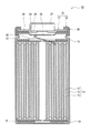
- FIG. 1 is a cross-sectional view of a secondary battery which is an example of an embodiment.
- the negative electrode for a secondary battery which is one aspect of the present disclosure, includes a negative electrode mixture layer having a negative electrode active material containing a Si compound, a conductive material, and a binder, and the conductive material has an outermost peripheral diameter of 5 nm.
- the binder comprises the following single-walled carbon nanotubes, and the binder contains a carboxymethyl cellulose salt having a weight average molecular weight of 150,000 or more and 450,000 or less. According to the negative electrode for a secondary battery, which is one aspect of the present disclosure, it is possible to suppress a decrease in charge / discharge cycle characteristics at a high rate. The mechanism that exerts the above effect is not clear, but the following can be considered.
- carboxymethyl cellulose salt as a binder is added to a slurry containing a negative electrode active material and carbon nanotubes during the production of a negative electrode
- the carboxymethyl cellulose salt generally exhibits hydrophilicity and therefore repels hydrophobic carbon nanotubes.
- Carbon nanotubes agglomerate.
- the single-walled carbon nanotubes are more likely to form a conductive network with the negative electrode active material containing the Si compound than the multi-walled carbon nanotubes, but since the single-walled carbon nanotubes are more hydrophobic than the multi-walled carbon nanotubes, the presence of the carboxymethyl cellulose salt is present.
- non-aqueous electrolyte secondary battery of the present disclosure is not limited to the embodiment described below. Further, the drawings referred to in the description of the embodiment are schematically described.
- FIG. 1 is a cross-sectional view of a secondary battery which is an example of an embodiment.
- the secondary battery 10 shown in FIG. 1 has a wound electrode body 14 in which a positive electrode 11 and a negative electrode 12 are wound via a separator 13, a non-aqueous electrolyte, and arranged above and below the electrode body 14, respectively.
- the insulating plates 18 and 19 and a battery case 15 for accommodating the above members are provided.
- the battery case 15 is composed of a bottomed cylindrical case body 16 and a sealing body 17 that closes an opening of the case body 16.
- the winding type electrode body 14 another form of an electrode body such as a laminated type electrode body in which positive electrodes and negative electrodes are alternately laminated via a separator may be applied.
- examples of the battery case 15 include a metal outer can such as a cylinder, a square, a coin, and a button, and a pouch outer body formed by laminating a resin sheet and a metal sheet.
- the case body 16 is, for example, a bottomed cylindrical metal outer can.
- a gasket 28 is provided between the case body 16 and the sealing body 17 to ensure the airtightness inside the battery.
- the case body 16 has an overhanging portion 22 that supports the sealing body 17, for example, a part of the side surface portion overhanging inward.
- the overhanging portion 22 is preferably formed in an annular shape along the circumferential direction of the case body 16, and the sealing body 17 is supported on the upper surface thereof.
- the sealing body 17 has a structure in which a filter 23, a lower valve body 24, an insulating member 25, an upper valve body 26, and a cap 27 are laminated in this order from the electrode body 14 side.
- Each member constituting the sealing body 17 has, for example, a disk shape or a ring shape, and each member except the insulating member 25 is electrically connected to each other.
- the lower valve body 24 and the upper valve body 26 are connected to each other at the central portion thereof, and an insulating member 25 is interposed between the peripheral portions thereof.
- the lower valve body 24 deforms and breaks so as to push the upper valve body 26 toward the cap 27 side, and the lower valve body 24 and the upper valve body 26 The current path between them is cut off.
- the upper valve body 26 breaks and gas is discharged from the opening of the cap 27.
- the positive electrode lead 20 attached to the positive electrode 11 extends toward the sealing body 17 through the through hole of the insulating plate 18, and the negative electrode lead 21 attached to the negative electrode 12 is the insulating plate 19. It extends to the bottom side of the case body 16 through the outside.
- the positive electrode lead 20 is connected to the lower surface of the filter 23, which is the bottom plate of the sealing body 17, by welding or the like, and the cap 27, which is the top plate of the sealing body 17 electrically connected to the filter 23, serves as the positive electrode terminal.
- the negative electrode lead 21 is connected to the inner surface of the bottom of the case body 16 by welding or the like, and the case body 16 serves as a negative electrode terminal.
- the negative electrode 12 has a negative electrode current collector made of, for example, a metal foil, and a negative electrode mixture layer formed on the current collector.
- a negative electrode current collector for example, a foil of a metal such as copper that is stable in the potential range of the negative electrode, a film in which the metal is arranged on the surface layer, or the like is used.
- the negative electrode mixture layer contains a negative electrode active material containing graphite particles and a Si compound, a binder, and a conductive material.
- a negative electrode mixture slurry containing a negative electrode active material, a binder, a conductive material, etc. is prepared, and this negative electrode mixture slurry is applied onto a negative electrode current collector and dried to form a negative electrode mixture layer. After that, it can be produced by performing a compression step of compressing the negative electrode mixture layer with a rolling roller or the like.
- the negative electrode active material contains a Si compound.
- the Si compound may be any material that can store and release lithium ions, but from the viewpoint of increasing the capacity of the secondary battery, the lithium ion conductive phase and the Si particles dispersed in the lithium ion conductive phase may be used. It is preferable to include, and the lithium ion conduction phase is preferably at least one selected from a silicate phase, a silicon oxide phase and a carbon phase.
- a conductive film made of a highly conductive material is formed on the surface of the Si compound particles.
- the constituent material of the conductive coating at least one selected from a carbon material, a metal, and a metal compound can be exemplified.
- a carbon material such as amorphous carbon is preferable.
- the carbon film can be formed by, for example, a CVD method using acetylene, methane, or the like, a method of mixing coal pitch, petroleum pitch, phenol resin, or the like with a silicon-based active material and performing heat treatment.
- a conductive film may be formed by fixing a conductive filler such as carbon black to the particle surface of the Si compound by using a binder.
- the Si compound include a silicate phase and a Si compound A containing Si particles dispersed in the silicate phase, a silicon oxide phase and a Si compound B containing Si particles dispersed in a silicon oxide phase, a carbon phase and a carbon phase.
- Si compound C containing dispersed Si particles. These may be used alone or in combination of two or more.
- the silicate phase of Si compound A is at least one selected from lithium, sodium, potassium, rubidium, cesium, francium, beryllium, magnesium, calcium, strontium, barium, radium and the like because of its high lithium ion conductivity and the like. It preferably contains an element. Among them, a silicate phase containing lithium (hereinafter, may be referred to as a lithium silicate phase) is preferable.
- the content of the silicon particles in the Si compound A is preferably 30% by mass or more and 80% by mass or less, preferably 35% by mass or more and 75% by mass, in terms of increasing the capacity and improving the charge / discharge cycle characteristics. It is preferably 55% by mass or more, and more preferably 70% by mass or less.
- the average particle size of the Si particles is preferably 500 nm or less, more preferably 200 nm or less, still more preferably 50 nm or less, for example, from the viewpoint of suppressing cracks in the Si particles themselves.
- the average particle size of the Si particles is preferably 400 nm or less, more preferably 100 nm or less.
- the average particle size of the Si particles is measured by observing a cross-sectional SEM (scanning electron microscope) photograph of the Si compound. Specifically, the average particle size of the Si particles is obtained by averaging the maximum diameters of any 100 Si particles.
- the Si compound B in which Si particles are dispersed in the silicon oxide phase is represented by, for example, the general formula SiO x (preferably in the range of 0 ⁇ x ⁇ 2, more preferably in the range of 0.5 ⁇ x ⁇ 1.6).
- the Si compound C in which Si particles are dispersed in the carbon phase is, for example, preferably in the range of the general formula Si xCy (0 ⁇ x ⁇ 1 and 0 ⁇ y ⁇ 1; 0.3 ⁇ x ⁇ 0.45 and 0". The range of .7 ⁇ y ⁇ 0.55 is more preferable).
- the content and average particle size of the Si particles in the Si compounds B and C may be the same as in the case of the Si compound A.
- the content of the Si compound in the negative electrode active material is, for example, 1% by mass or more with respect to the mass of the negative electrode active material in terms of suppressing the increase in capacity of the secondary battery and the deterioration of charge / discharge cycle characteristics. It is preferably 10% by mass or less.
- the negative electrode active material preferably contains graphite particles in terms of suppressing deterioration of the charge / discharge cycle characteristics of the secondary battery.
- the graphite particles are not particularly limited to natural graphite, artificial graphite and the like.
- the surface spacing (d 002 ) of the (002) plane of the graphite particles by the X-ray wide-angle diffraction method is, for example, preferably 0.3354 nm or more, more preferably 0.3357 nm or more, and 0.340 nm. It is preferably less than, more preferably 0.338 nm or less.
- the crystallite size (Lc (002)) determined by the X-ray diffraction method of the graphite particles is, for example, preferably 5 nm or more, more preferably 10 nm or more, and more preferably 300 nm or less. It is preferably 200 nm or less, and more preferably 200 nm or less.
- the content of the graphite particles in the negative electrode active material is, for example, 80% by mass or more with respect to the mass of the negative electrode active material in terms of suppressing the increase in capacity of the secondary battery and the deterioration of charge / discharge cycle characteristics. It is preferably 90% by mass or less.
- the content of the negative electrode active material in the negative electrode mixture layer is, for example, preferably 85% by mass or more, more preferably 90% by mass or more, and 95% by mass, based on the mass of the negative electrode mixture layer. The above is more preferable.
- the conductive material contained in the negative electrode mixture layer includes single-walled carbon nanotubes.
- the single-walled carbon nanotube (SWCNT) is a carbon nanostructure in which one layer of graphene sheet constitutes one cylindrical shape.
- the graphene sheet refers to a layer in which carbon atoms of sp2 hybrid orbitals constituting graphite crystals are located at the vertices of a regular hexagon.
- the shape of the single-walled carbon nanotube is not limited, and examples thereof include a needle shape, a cylindrical tube shape, a fish bone shape (fishbone or cup laminated type), a playing card shape (platelet), and a coil shape. ..
- the outermost peripheral diameter (that is, the fiber diameter) of the single-walled carbon nanotube may be 5 nm or less, but preferably 1 nm or more and 3 nm or less, for example, in terms of easily forming a conductive network with the negative electrode active material. Is preferable.
- the outermost diameter of the single-walled carbon nanotubes can be determined by measuring the outer diameters of 50 arbitrary carbon nanotubes with a field emission scanning microscope (FE-SEM) or a transmission electron microscope (TEM) and averaging them.
- the fiber length of the single-walled carbon nanotubes is preferably 500 nm or more and 200 ⁇ m or less, and preferably 1 ⁇ m or more and 100 ⁇ m or less, for example, in terms of efficiently forming a conductive network with a negative electrode active material.
- the fiber length of the single-walled carbon nanotubes can be determined by measuring the lengths of 50 arbitrary single-walled carbon nanotubes with a field emission scanning microscope (FE-SEM) and arithmetically averaging them.
- the content of the single-walled carbon nanotubes is 0.001% by mass or more and 0.1% by mass or less with respect to the mass of the negative electrode active material in terms of efficiently forming a conductive network with the negative electrode active material, for example. It is preferably 0.001% by mass or more, and more preferably 0.01% by mass or less.
- the conductive material may contain multi-walled carbon nanotubes in addition to the single-walled carbon nanotubes as long as the effects of the present disclosure are not impaired.
- the multi-walled carbon nanotube is a carbon nanostructure in which two or more graphene sheets are laminated concentrically to form one cylindrical shape.
- the conductive material may contain particulate conductive material, if necessary.
- the particulate conductive material include carbon materials such as carbon black, acetylene black, ketjen black, and graphite.
- its primary particle diameter is preferably 5 nm or more and 100 nm or less, and the aspect ratio is preferably less than 10.
- the binder contains a carboxymethyl cellulose salt.
- carboxymethyl cellulose salt examples include sodium carboxymethyl cellulose salt (CMC-Na), potassium carboxymethyl cellulose salt (CMC-K) and the like.
- the weight average molecular weight of the carboxymethyl cellulose salt may be 150,000 or more and 450,000 or less, but preferably 200,000 or more and 400,000 or less, in terms of suppressing deterioration of charge / discharge cycle characteristics at a high rate.
- the weight average molecular weight of the carboxymethyl cellulose salt satisfies the above range, as described above, the hydrophilicity can be moderately relaxed while maintaining the binding performance. Therefore, a single layer in the presence of the carboxymethyl cellulose salt. Aggregation of carbon nanotubes is suppressed.
- the degree of etherification of the carboxymethyl cellulose salt is preferably 0.5 or more and 1.5 or less, and 0.6 or more and 1.1 or less, in terms of suppressing deterioration of charge / discharge cycle characteristics at high rates. It is more preferable to have.
- the degree of etherification is measured by the ashing titration method.
- the weight average molecular weight of the carboxymethyl cellulose salt can be controlled by, for example, the crushing treatment conditions of the raw material cellulose and the raw material cellulose, and the degree of etherification can be controlled by, for example, the reaction treatment conditions with chloroacetic acid and its salt, and / or an alkaline agent. Can be controlled by adjusting.
- the content of the carboxymethyl cellulose salt is preferably 1% by mass or more and 3% by mass or less with respect to the mass of the negative electrode active material, for example, in terms of suppressing deterioration of charge / discharge cycle characteristics at a high rate. It is more preferably 1.5% by mass or more and 2.5% by mass or less.
- the binder may be, for example, a fluororesin, a PAN, a polyimide resin, an acrylic resin, a polyolefin resin, a styrene-butadiene rubber (SBR), a polyacrylic acid (PAA) or a salt thereof.
- PVA Polyvinyl alcohol
- the positive electrode 11 is composed of a positive electrode current collector such as a metal foil and a positive electrode mixture layer formed on the positive electrode current collector.
- a positive electrode current collector a foil of a metal such as aluminum that is stable in the potential range of the positive electrode, a film in which the metal is arranged on the surface layer, or the like can be used.
- the positive electrode mixture layer contains, for example, a positive electrode active material, a binder, a conductive material and the like.
- a positive electrode mixture slurry containing a positive electrode active material, a binder, a conductive material, etc. is applied onto a positive electrode current collector and dried to form a positive electrode mixture layer, and then the positive electrode 11 is formed by a rolling roller or the like. It can be produced by performing a compression step of compressing the positive electrode mixture layer.
- Examples of the positive electrode active material include lithium transition metal oxides containing transition metal elements such as Co, Mn, and Ni.
- Lithium transition metal oxides include, for example, Li x CoO 2 , Li x NiO 2 , Li x MnO 2 , Li x Coy Ni 1-y O 2 , Li x Coy M 1-y O z , Li x Ni 1- y My O z , Li x Mn 2 O 4 , Li x Mn 2-y My O 4 , LiMPO 4 , Li 2 MPO 4 F (M; Na, Mg, Sc, Y, Mn, Fe, Co, Ni , Cu, Zn, Al, Cr, Pb, Sb, B, 0 ⁇ x ⁇ 1.2, 0 ⁇ y ⁇ 0.9, 2.0 ⁇ z ⁇ 2.3).
- the positive electrode active materials are Li x NiO 2 , Li x Coy Ni 1-y O 2 , and Li x Ni 1-y My Oz (M; Na). , Mg, Sc, Y, Mn, Fe, Co, Ni, Cu, Zn, Al, Cr, Pb, Sb, B, at least one of 0 ⁇ x ⁇ 1.2, 0 ⁇ y ⁇ 0.9, It is preferable to contain a lithium nickel composite oxide such as 2.0 ⁇ z ⁇ 2.3).
- Examples of the conductive material include carbon particles such as carbon black (CB), acetylene black (AB), Ketjen black, and graphite. These may be used alone or in combination of two or more.
- binder examples include fluororesins such as polytetrafluoroethylene (PTFE) and polyvinylidene fluoride (PVdF), polyacrylonitrile (PAN), polyimide resins, acrylic resins, and polyolefin resins. These may be used alone or in combination of two or more.
- fluororesins such as polytetrafluoroethylene (PTFE) and polyvinylidene fluoride (PVdF), polyacrylonitrile (PAN), polyimide resins, acrylic resins, and polyolefin resins. These may be used alone or in combination of two or more.
- a porous sheet having ion permeability and insulating property is used.
- the porous sheet include a microporous thin film, a woven fabric, and a non-woven fabric.
- an olefin resin such as polyethylene and polypropylene, cellulose and the like are suitable.
- the separator 13 may be a laminate having a cellulose fiber layer and a thermoplastic resin fiber layer such as an olefin resin.
- a multilayer separator including a polyethylene layer and a polypropylene layer may be used, or a separator having a surface coated with a material such as an aramid resin or ceramic may be used.
- the non-aqueous electrolyte contains a non-aqueous solvent and an electrolyte salt dissolved in the non-aqueous solvent.
- the non-aqueous electrolyte is not limited to the liquid electrolyte (electrolyte solution), and may be a solid electrolyte using a gel-like polymer or the like.
- the non-aqueous solvent for example, esters, ethers, nitriles such as acetonitrile, amides such as dimethylformamide, and a mixed solvent of two or more of these can be used.
- the non-aqueous solvent may contain a halogen-substituted product in which at least a part of hydrogen in these solvents is substituted with a halogen atom such as fluorine.
- esters examples include cyclic carbonate esters such as ethylene carbonate (EC), propylene carbonate (PC) and butylene carbonate, dimethyl carbonate (DMC), ethyl methyl carbonate (EMC), diethyl carbonate (DEC) and methylpropyl carbonate.
- cyclic carbonate esters such as ethylene carbonate (EC), propylene carbonate (PC) and butylene carbonate, dimethyl carbonate (DMC), ethyl methyl carbonate (EMC), diethyl carbonate (DEC) and methylpropyl carbonate.
- ethers examples include 1,3-dioxolane, 4-methyl-1,3-dioxolane, tetrahydrofuran, 2-methyltetrahexyl, propylene oxide, 1,2-butylene oxide, 1,3-dioxane, 1,4.
- -Cyclic ethers such as dioxane, 1,3,5-trioxane, furan, 2-methylfuran, 1,8-cineole, crown ether, 1,2-dimethoxyethane, diethyl ether, dipropyl ether, diisopropyl ether, dibutyl ether , Dihexyl ether, ethyl vinyl ether, butyl vinyl ether, methyl phenyl ether, ethyl phenyl ether, butyl phenyl ether, pentyl phenyl ether, methoxy toluene, benzyl ethyl ether, diphenyl ether, dibenzyl ether, o-dimethoxybenzene, 1,2-diethoxy Chain ethers such as ethane, 1,2-dibutoxyethane, diethylene glycol dimethyl ether, diethylene glycol diethyl ether, diethylene glycol dibutyl
- a fluorinated cyclic carbonate ester such as fluoroethylene carbonate (FEC), a fluorinated chain carbonate ester, a fluorinated chain carboxylic acid ester such as methyl fluoropropionate (FMP), or the like. ..
- the electrolyte salt is preferably a lithium salt.
- lithium salts include LiBF 4 , LiClO 4 , LiPF 6 , LiAsF 6 , LiSbF 6 , LiAlCl 4 , LiSCN, LiCF 3 SO 3 , LiCF 3 CO 2 , Li (P (C 2 O 4 ) F 4 ), LiPF 6-x (C n F 2n + 1 ) x (1 ⁇ x ⁇ 6, n is 1 or 2 ), LiB 10 Cl 10 , LiCl, LiBr, LiI, chloroborane lithium, lower aliphatic carboxylate lithium, Li 2B 4 O 7 , borates such as Li (B (C 2 O 4 ) F 2 ), LiN (SO 2 CF 3 ) 2 , LiN (C 1 F 2l + 1 SO 2 ) (C m F 2m + 1 SO 2 ) ⁇ l , M is an integer of 1 or more ⁇ and other imide salts.
- lithium salt these may be used alone or in combination of two or more.
- LiPF 6 is preferably used from the viewpoint of ionic conductivity, electrochemical stability, and the like.
- concentration of the lithium salt is preferably 0.8 to 1.8 mol per 1 L of the solvent.
- Example 1 [Manufacturing of negative electrode] Graphite particles and Si compound were mixed so as to have a mass ratio of 90:10. This mixture was used as a negative electrode active material.
- single-walled carbon nanotubes (SWCNTs) having an outermost outer diameter of 1 to 3 nm, and carboxymethyl cellulose sodium salt (CMC-Na) having a weight average molecular weight of 20 ⁇ 106 and an etherification degree of 1.1 were prepared. Then, these are mixed so that the mass ratio of the negative electrode active material: SWCNT: CMC-Na: styrene-butadiene copolymer rubber (SBR) is 100: 0.01: 1.5: 2, and the negative electrode combination is performed.
- SWCNT CMC-Na: styrene-butadiene copolymer rubber
- a material slurry was prepared. This slurry is applied to both sides of a current collector made of copper foil by the doctor blade method, the coating film is dried, and then the coating film is compressed by a rolling roller to form negative electrode mixture layers on both sides of the negative electrode current collector.
- the negative electrode was prepared.
- Preparation of positive electrode Aluminum-containing lithium nickel cobalt oxide (LiNi 0.88 Co 0.09 Al 0.03 O 2 ) was used as the positive electrode active material. 100 parts by mass of the above positive electrode active material, 1 part by mass of acetylene black, and 0.9 parts by mass of polyvinylidene fluoride are mixed in a solvent of N-methyl-2-pyrrolidone (NMP) to prepare a positive electrode mixture. A slurry was prepared. This slurry is applied to both sides of an aluminum foil having a thickness of 15 ⁇ m, the coating film is dried, and then the coating film is rolled by a rolling roller to obtain a positive electrode having a positive electrode mixture layer formed on both sides of a positive electrode current collector. Made.
- NMP N-methyl-2-pyrrolidone
- LiPF 6 LiPF 6 at a concentration of 1.4 mol / L in a non-aqueous solvent in which ethylene carbonate (EC), methyl ethyl carbonate (MEC), and dimethyl carbonate (DMC) were mixed at a volume ratio of 20: 5: 75.
- EC ethylene carbonate
- MEC methyl ethyl carbonate
- DMC dimethyl carbonate
- 3% by mass of vinylene carbonate and 0.5% by mass of 1,6-diisocyanate hexane were added. This was used as a non-aqueous electrolyte.
- Example 2 A secondary battery was produced in the same manner as in Example 1 except that CMC-Na having a weight average molecular weight of 30 ⁇ 10 6 and an etherification degree of 1.1 was used.
- Example 3 A secondary battery was produced in the same manner as in Example 1 except that CMC-Na having a weight average molecular weight of 40 ⁇ 106 and an etherification degree of 1.1 was used.
- Example 4 Except for the fact that CMC-Na of Example 2 was used and that the negative electrode active material: SWCNT: CMC-Na: SBR was mixed so that the mass ratio was 100: 0.001: 1.5: 2. , A secondary battery was produced in the same manner as in Example 1.
- Example 5 Except for the fact that CMC-Na of Example 2 was used and that the negative electrode active material: SWCNT: CMC-Na: SBR was mixed so that the mass ratio was 100: 0.05: 1.5: 2. , A secondary battery was produced in the same manner as in Example 1.
- Example 6 Except for the fact that CMC-Na of Example 2 was used and that the negative electrode active material: SWCNT: CMC-Na: SBR was mixed so that the mass ratio was 100: 0.1: 1.5: 2. , A secondary battery was produced in the same manner as in Example 1.
- Example 7 A secondary battery was produced in the same manner as in Example 1 except that CMC-Na having a weight average molecular weight of 30 ⁇ 10 6 and an etherification degree of 0.5 was used.
- Example 8 A secondary battery was produced in the same manner as in Example 1 except that CMC-Na having a weight average molecular weight of 30 ⁇ 10 6 and an etherification degree of 0.6 was used.
- Example 9 A secondary battery was produced in the same manner as in Example 1 except that CMC-Na having a weight average molecular weight of 30 ⁇ 10 6 and an etherification degree of 1.5 was used.
- Example 10 A secondary battery was produced in the same manner as in Example 1 except that CMC-Na having a weight average molecular weight of 30 ⁇ 106 and an etherification degree of 1.6 was used.
- Example 11 A secondary battery was produced in the same manner as in Example 1 except that CMC-Na having a weight average molecular weight of 30 ⁇ 10 6 and an etherification degree of 0.3 was used.
- Example 12 A secondary battery was produced in the same manner as in Example 1 except that CMC-Na having a weight average molecular weight of 30 ⁇ 106 and an etherification degree of 1,8 was used.
- Example 1 CMC-Na with a weight average molecular weight of 10 ⁇ 10 6 and an etherification degree of 1.1 was used, and the mass ratio of the negative electrode active material: CMC-Na: SBR was 100: 1.5: 2.
- a secondary battery was produced in the same manner as in Example 1 except that it was mixed.
- Example 4 CMC-Na with a weight average molecular weight of 40 ⁇ 106 and an etherification degree of 1.1 was used, and the mass ratio of the negative electrode active material: CMC-Na: SBR was 100: 1.5: 2.
- a secondary battery was produced in the same manner as in Example 1 except that it was mixed.
- Example 5 CMC-Na with a weight average molecular weight of 50 ⁇ 106 and an etherification degree of 1.1 was used, and the mass ratio of the negative electrode active material: CMC-Na: SBR was 100: 1.5: 2.
- a secondary battery was produced in the same manner as in Example 1 except that it was mixed.
- Example 6 CMC-Na with a weight average molecular weight of 30 ⁇ 106 and an etherification degree of 0.3 was used, and the mass ratio of the negative electrode active material: CMC-Na: SBR was 100: 1.5: 2.
- a secondary battery was produced in the same manner as in Example 1 except that it was mixed.
- Example 7 CMC-Na with a weight average molecular weight of 30 ⁇ 106 and an etherification degree of 0.5 was used, and the mass ratio of the negative electrode active material: CMC-Na: SBR was 100: 1.5: 2.
- a secondary battery was produced in the same manner as in Example 1 except that it was mixed.
- Example 8 CMC-Na with a weight average molecular weight of 30 ⁇ 106 and an etherification degree of 0.6 was used, and the mass ratio of the negative electrode active material: CMC-Na: SBR was 100: 1.5: 2.
- a secondary battery was produced in the same manner as in Example 1 except that it was mixed.
- Example 9 CMC-Na with a weight average molecular weight of 30 ⁇ 106 and an etherification degree of 1.5 was used, and the mass ratio of the negative electrode active material: CMC-Na: SBR was 100: 1.5: 2.
- a secondary battery was produced in the same manner as in Example 1 except that it was mixed.
- Example 10 CMC-Na with a weight average molecular weight of 30 ⁇ 106 and an etherification degree of 1.6 was used, and the mass ratio of the negative electrode active material: CMC-Na: SBR was 100: 1.5: 2.
- a secondary battery was produced in the same manner as in Example 1 except that it was mixed.
- Example 12 A secondary battery was produced in the same manner as in Example 1 except that CMC-Na having a weight average molecular weight of 10 ⁇ 10 6 and an etherification degree of 1.1 was used.
- Example 13 A secondary battery was produced in the same manner as in Example 1 except that CMC-Na having a weight average molecular weight of 50 ⁇ 106 and an etherification degree of 1.1 was used.
- Example 14 A secondary battery was produced in the same manner as in Example 1 except that a multi-walled carbon nanotube (MWCNT) having an outermost peripheral diameter of 11 nm was used and CMC-Na of Example 2 was used.
- MWCNT multi-walled carbon nanotube
- Capacity retention rate (%) (50th cycle discharge capacity ⁇ 1st cycle discharge capacity) x 100
- Table 1 summarizes the results of capacity retention in the high-rate charge / discharge cycle tests of Examples and Comparative Examples. It should be noted that the higher the value of the capacity retention rate, the more the deterioration of the charge / discharge cycle characteristics at a high rate was suppressed.
Landscapes
- Chemical & Material Sciences (AREA)
- Chemical Kinetics & Catalysis (AREA)
- Electrochemistry (AREA)
- General Chemical & Material Sciences (AREA)
- Engineering & Computer Science (AREA)
- Materials Engineering (AREA)
- Manufacturing & Machinery (AREA)
- Composite Materials (AREA)
- Inorganic Chemistry (AREA)
- Battery Electrode And Active Subsutance (AREA)
Abstract
Description
負極12は、例えば金属箔等からなる負極集電体と、当該集電体上に形成された負極合材層とを有する。負極集電体には、例えば、銅などの負極の電位範囲で安定な金属の箔、当該金属を表層に配置したフィルム等が用いられる。負極合材層は、黒鉛粒子及びSi化合物を含む負極活物質、結着材、導電材を含む。
正極11は、例えば金属箔等の正極集電体と、正極集電体上に形成された正極合材層とで構成される。正極集電体には、アルミニウムなどの正極の電位範囲で安定な金属の箔、当該金属を表層に配置したフィルム等を用いることができる。正極合材層は、例えば、正極活物質、結着材、導電材等を含む。
セパレータ13には、例えば、イオン透過性及び絶縁性を有する多孔性シート等が用いられる。多孔性シートの具体例としては、微多孔薄膜、織布、不織布等が挙げられる。セパレータの材質としては、ポリエチレン、ポリプロピレン等のオレフィン系樹脂、セルロースなどが好適である。セパレータ13は、セルロース繊維層及びオレフィン系樹脂等の熱可塑性樹脂繊維層を有する積層体であってもよい。また、ポリエチレン層及びポリプロピレン層を含む多層セパレータであってもよく、セパレータの表面にアラミド系樹脂、セラミック等の材料が塗布されたものを用いてもよい。
非水電解質は、非水溶媒と、非水溶媒に溶解した電解質塩とを含む。非水電解質は、液体電解質(電解液)に限定されず、ゲル状ポリマー等を用いた固体電解質であってもよい。非水溶媒には、例えばエステル類、エーテル類、アセトニトリル等のニトリル類、ジメチルホルムアミド等のアミド類、及びこれらの2種以上の混合溶媒等を用いることができる。非水溶媒は、これら溶媒の水素の少なくとも一部をフッ素等のハロゲン原子で置換したハロゲン置換体を含有していてもよい。
以下、実施例により本開示をさらに説明するが、本開示はこれらの実施例に限定されるものではない。
[負極の作製]
黒鉛粒子と、Si化合物とを、質量比で、90:10となるようにこれらを混合した。この混合物を負極活物質とした。また、最外周径1~3nmの単層カーボンナノチューブ(SWCNT)、及び重量平均分子量20×106、エーテル化度1.1のカルボキシメチルセルロースナトリウム塩(CMC-Na)を準備した。そして、負極活物質:SWCNT:CMC-Na:スチレン-ブタジエン共重合体ゴム(SBR)の質量比が、100:0.01:1.5:2となるようにこれらを混合して、負極合材スラリーを調製した。このスラリーを銅箔からなる集電体の両面にドクターブレード法により塗布し、塗膜を乾燥した後、圧延ローラにより塗膜を圧縮して、負極集電体の両面に負極合材層が形成された負極を作製した。
正極活物質として、アルミニウム含有ニッケルコバルト酸リチウム(LiNi0.88Co0.09Al0.03O2)を用いた。100質量部の上記正極活物質と、1質量部のアセチレンブラックと、0.9質量部のポリフッ化ビニリデンを、N-メチル-2-ピロリドン(NMP)の溶剤中で混合して、正極合材スラリーを調製した。このスラリーを厚さ15μmのアルミニウム箔の両面に塗布し、塗膜を乾燥した後、圧延ローラにより塗膜を圧延することにより、正極集電体の両面に正極合材層が形成された正極を作製した。
エチレンカーボネート(EC)と、メチルエチルカーボネート(MEC)、ジメチルカーボネート(DMC)とを体積比で20:5:75となるように混合した非水溶媒に、LiPF6を1.4mol/Lの濃度で溶解し、さらに、ビニレンカーボネートを3質量%、1,6-ジイソシアネートヘキサンを0.5質量%添加した。これを非水電解質とした。
(1)正極集電体にアルミニウム製の正極リードを取り付け、負極集電体にニッケル-銅-ニッケル製の負極リードを取り付けた後、正極と負極との間に、ポリエチレン製のセパレータを介して巻回し、巻回型の電極体を作製した。
(2)電極体の上下に絶縁板をそれぞれ配置し、負極リードをケース本体に溶接し、正極リードを封口体に溶接して、電極体をケース本体内に収容した。
(3)ケース本体内に非水電解質を減圧方式により注入した後、ケース本体の開口端部を、ガスケットを介して封口体にかしめた。これを二次電池とした。
重量平均分子量30×106、エーテル化度1.1のCMC-Naを用いたこと以外は、実施例1と同様に二次電池を作製した。
重量平均分子量40×106、エーテル化度1.1のCMC-Naを用いたこと以外は、実施例1と同様に二次電池を作製した。
実施例2のCMC-Naを用いたこと、負極活物質:SWCNT:CMC-Na:SBRの質量比が、100:0.001:1.5:2となるようにこれらを混合したこと以外は、実施例1と同様に二次電池を作製した。
実施例2のCMC-Naを用いたこと、負極活物質:SWCNT:CMC-Na:SBRの質量比が、100:0.05:1.5:2となるようにこれらを混合したこと以外は、実施例1と同様に二次電池を作製した。
実施例2のCMC-Naを用いたこと、負極活物質:SWCNT:CMC-Na:SBRの質量比が、100:0.1:1.5:2となるようにこれらを混合したこと以外は、実施例1と同様に二次電池を作製した。
重量平均分子量30×106、エーテル化度0.5のCMC-Naを用いたこと以外は、実施例1と同様に二次電池を作製した。
重量平均分子量30×106、エーテル化度0.6のCMC-Naを用いたこと以外は、実施例1と同様に二次電池を作製した。
重量平均分子量30×106、エーテル化度1.5のCMC-Naを用いたこと以外は、実施例1と同様に二次電池を作製した。
重量平均分子量30×106、エーテル化度1.6のCMC-Naを用いたこと以外は、実施例1と同様に二次電池を作製した。
重量平均分子量30×106、エーテル化度0.3のCMC-Naを用いたこと以外は、実施例1と同様に二次電池を作製した。
重量平均分子量30×106、エーテル化度1,8のCMC-Naを用いたこと以外は、実施例1と同様に二次電池を作製した。
重量平均分子量10×106、エーテル化度1.1のCMC-Naを用いたこと、負極活物質:CMC-Na:SBRの質量比が、100:1.5:2となるようにこれらを混合したこと以外は、実施例1と同様に二次電池を作製した。
重量平均分子量20×106、エーテル化度1.1のCMC-Naを用いたこと、負極活物質:CMC-Na:SBRの質量比が、100:1.5:2となるようにこれらを混合したこと以外は、比較例1と同様に二次電池を作製した。
重量平均分子量30×106、エーテル化度1.1のCMC-Naを用いた、負極活物質:CMC-Na:SBRの質量比が、100:1.5:2となるようにこれらを混合したこと以外は、実施例1と同様に二次電池を作製した。
重量平均分子量40×106、エーテル化度1.1のCMC-Naを用いたこと、負極活物質:CMC-Na:SBRの質量比が、100:1.5:2となるようにこれらを混合したこと以外は、実施例1と同様に二次電池を作製した。
重量平均分子量50×106、エーテル化度1.1のCMC-Naを用いたこと、負極活物質:CMC-Na:SBRの質量比が、100:1.5:2となるようにこれらを混合したこと以外は、実施例1と同様に二次電池を作製した。
重量平均分子量30×106、エーテル化度0.3のCMC-Naを用いたこと、負極活物質:CMC-Na:SBRの質量比が、100:1.5:2となるようにこれらを混合したこと以外は、実施例1と同様に二次電池を作製した。
重量平均分子量30×106、エーテル化度0.5のCMC-Naを用いたこと、負極活物質:CMC-Na:SBRの質量比が、100:1.5:2となるようにこれらを混合したこと以外は、実施例1と同様に二次電池を作製した。
重量平均分子量30×106、エーテル化度0.6のCMC-Naを用いたこと、負極活物質:CMC-Na:SBRの質量比が、100:1.5:2となるようにこれらを混合したこと以外は、実施例1と同様に二次電池を作製した。
重量平均分子量30×106、エーテル化度1.5のCMC-Naを用いたこと、負極活物質:CMC-Na:SBRの質量比が、100:1.5:2となるようにこれらを混合したこと以外は、実施例1と同様に二次電池を作製した。
重量平均分子量30×106、エーテル化度1.6のCMC-Naを用いたこと、負極活物質:CMC-Na:SBRの質量比が、100:1.5:2となるようにこれらを混合したこと以外は、実施例1と同様に二次電池を作製した。
重量平均分子量30×106、エーテル化度1.8のCMC-Naを用いたこと、負極活物質:CMC-Na:SBRの質量比が、100:1.5:2となるようにこれらを混合したこと以外は、実施例1と同様に二次電池を作製した。
重量平均分子量10×106、エーテル化度1.1のCMC-Naを用いたこと以外は、実施例1と同様に二次電池を作製した。
重量平均分子量50×106、エーテル化度1.1のCMC-Naを用いたこと以外は、実施例1と同様に二次電池を作製した。
最外周径11nmの多層カーボンナノチューブ(MWCNT)を用いたこと、実施例2のCMC-Naを用いたこと以外は、実施例1と同様に二次電池を作製した。
実施例及び比較例の各二次電池を、25℃の温度環境下、1Cの定電流で電池電圧が4.2Vになるまで定電流充電を行い、その後、1Cの定電流で電池電圧が2.5Vになるまで定電流放電を行った。この高レートでの充放電サイクルを50サイクル繰り返し、下記式により容量維持率を算出した。
表1に、実施例及び比較例の高レートでの充放電サイクル試験における容量維持率の結果をまとめた。なお、容量維持率の値が高いほど、高レートでの充放電サイクル特性の低下が抑制されたことを示している。

11 正極
12 負極
13 セパレータ
14 電極体
15 電池ケース
16 ケース本体
17 封口体
18,19 絶縁板
20 正極リード
21 負極リード
22 張り出し部
23 フィルタ
24 下弁体
25 絶縁部材
26 上弁体
27 キャップ
28 ガスケット
Claims (11)
- Si化合物を含む負極活物質と、導電材と、結着材とを有する負極合材層を備え、
前記導電材は、最外周径が5nm以下の単層カーボンナノチューブを含み、
結着材は、重量平均分子量が15万以上、45万以下のカルボキシメチルセルロース塩を含む、二次電池用負極。 - 前記単層カーボンナノチューブの最外周径は、1nm以上、3nm以下である、請求項1に記載の二次電池用負極。
- 前記単層カーボンナノチューブの含有量は、前記負極活物質の質量に対して、0.001質量%以上、0.1質量%以下である、請求項1又は2に記載の二次電池用負極。
- 前記単層カーボンナノチューブの含有量は、前記負極活物質の質量に対して、0.001質量%以上、0.05質量%以下である、請求項3に記載の二次電池用負極。
- 前記単層カーボンナノチューブの含有量は、前記負極活物質の質量に対して、0.001質量%以上、0.01質量%以下である、請求項4に記載の二次電池用負極。
- 前記カルボキシメチルセルロース塩のエーテル化度は、0.5以上、1.6以下である、請求項1~5のいずれか1項に記載の二次電池用負極。
- 前記カルボキシメチルセルロース塩のエーテル化度は、0.6以上、1.1以下である、請求項6に記載の二次電池用負極。
- 前記カルボキシメチルセルロース塩の重量平均分子量は、20万以上、40万以下である、請求項1~7のいずれか1項に記載の二次電池用負極。
- 前記Si化合物は、リチウムイオン伝導相と、前記リチウムイオン伝導相内に分散しているシリコン粒子とを含む、請求項1~8のいずれか1項に記載の二次電池用負極。
- 前記リチウムイオン伝導相は、シリケート及び酸化ケイ素のうち少なくともいずれか一方を含む、請求項9に記載の二次電池用負極。
- 正極、負極、非水電解質を備え、
前記負極は、請求項1~10のいずれか1項に記載の二次電池用負極である、二次電池。
Priority Applications (4)
| Application Number | Priority Date | Filing Date | Title |
|---|---|---|---|
| EP21875197.2A EP4224565A4 (en) | 2020-09-30 | 2021-09-14 | NEGATIVE ELECTRODE FOR SECONDARY BATTERY, AND SECONDARY BATTERY |
| CN202180064760.7A CN116195089A (zh) | 2020-09-30 | 2021-09-14 | 二次电极用负极及二次电池 |
| JP2022553787A JP7738268B2 (ja) | 2020-09-30 | 2021-09-14 | 二次電池用負極及び二次電池 |
| US18/028,011 US20230343942A1 (en) | 2020-09-30 | 2021-09-14 | Negative electrode for secondary battery, and secondary battery |
Applications Claiming Priority (2)
| Application Number | Priority Date | Filing Date | Title |
|---|---|---|---|
| JP2020165816 | 2020-09-30 | ||
| JP2020-165816 | 2020-09-30 |
Publications (1)
| Publication Number | Publication Date |
|---|---|
| WO2022070895A1 true WO2022070895A1 (ja) | 2022-04-07 |
Family
ID=80951437
Family Applications (1)
| Application Number | Title | Priority Date | Filing Date |
|---|---|---|---|
| PCT/JP2021/033790 Ceased WO2022070895A1 (ja) | 2020-09-30 | 2021-09-14 | 二次電池用負極及び二次電池 |
Country Status (5)
| Country | Link |
|---|---|
| US (1) | US20230343942A1 (ja) |
| EP (1) | EP4224565A4 (ja) |
| JP (1) | JP7738268B2 (ja) |
| CN (1) | CN116195089A (ja) |
| WO (1) | WO2022070895A1 (ja) |
Cited By (8)
| Publication number | Priority date | Publication date | Assignee | Title |
|---|---|---|---|---|
| JP7194860B1 (ja) | 2022-09-30 | 2022-12-22 | 第一工業製薬株式会社 | カーボンナノチューブ分散液、及びそれを用いた電極用塗料、電極、非水電解質二次電池 |
| JP2023181116A (ja) * | 2022-06-10 | 2023-12-21 | ツィンファ ユニバーシティ | リチウムイオン電池の陽極の製造方法 |
| JP2023181115A (ja) * | 2022-06-10 | 2023-12-21 | ツィンファ ユニバーシティ | リチウムイオン電池の陽極 |
| JP2024046301A (ja) * | 2022-09-22 | 2024-04-03 | 株式会社豊田自動織機 | 蓄電装置用の電極、及び活物質層用の合材の製造方法 |
| WO2024247945A1 (ja) * | 2023-05-31 | 2024-12-05 | パナソニックIpマネジメント株式会社 | 非水電解質二次電池 |
| WO2024247965A1 (ja) * | 2023-05-31 | 2024-12-05 | パナソニックIpマネジメント株式会社 | 非水電解質二次電池 |
| WO2025028531A1 (ja) * | 2023-07-31 | 2025-02-06 | パナソニックエナジー株式会社 | 非水電解質二次電池 |
| WO2025028532A1 (ja) * | 2023-07-31 | 2025-02-06 | パナソニックエナジー株式会社 | 非水電解質二次電池 |
Citations (4)
| Publication number | Priority date | Publication date | Assignee | Title |
|---|---|---|---|---|
| JP2016110876A (ja) | 2014-12-08 | 2016-06-20 | 三星エスディアイ株式会社Samsung SDI Co., Ltd. | リチウムイオン二次電池用負極、およびリチウムイオン二次電池 |
| JP2017084759A (ja) * | 2015-10-30 | 2017-05-18 | 大阪瓦斯株式会社 | 電極活物質−カーボンナノチューブコンポジット及びその製造方法 |
| JP2019164887A (ja) * | 2018-03-19 | 2019-09-26 | 株式会社エンビジョンAescエナジーデバイス | 負極製造用ペーストの製造方法、電池用負極電極、電池および電池用負極電極の製造方法 |
| WO2020175172A1 (ja) * | 2019-02-27 | 2020-09-03 | パナソニックIpマネジメント株式会社 | 巻回型非水電解質二次電池 |
Family Cites Families (11)
| Publication number | Priority date | Publication date | Assignee | Title |
|---|---|---|---|---|
| KR101441712B1 (ko) * | 2006-12-26 | 2014-09-17 | 미쓰비시 가가꾸 가부시키가이샤 | 비수계 2차전지용 복합 흑연 입자, 그것을 함유하는 부극 재료, 부극 및 비수계 2차전지 |
| JP5602262B2 (ja) * | 2013-01-29 | 2014-10-08 | 昭和電工株式会社 | 複合電極材 |
| KR102231209B1 (ko) * | 2014-05-22 | 2021-03-22 | 삼성에스디아이 주식회사 | 리튬 이차 전지용 음극 및 이를 포함하는 리튬 이차 전지 |
| JP6476882B2 (ja) * | 2015-01-16 | 2019-03-06 | 東洋インキScホールディングス株式会社 | 導電性組成物、蓄電デバイス用下地層付き集電体、蓄電デバイス用電極、及び蓄電デバイス |
| KR102368307B1 (ko) * | 2015-09-16 | 2022-03-02 | 삼성전자주식회사 | 전극 활물질, 이를 포함하는 전극 및 이차전지, 및 상기 전극 활물질의 제조방법 |
| DE102016202458A1 (de) * | 2016-02-17 | 2017-08-17 | Wacker Chemie Ag | Verfahren zur Herstellung von Si/C-Kompositpartikeln |
| WO2018146865A1 (ja) * | 2017-02-09 | 2018-08-16 | 株式会社村田製作所 | 二次電池、電池パック、電動車両、電動工具および電子機器 |
| KR102703667B1 (ko) * | 2019-06-28 | 2024-09-06 | 주식회사 엘지에너지솔루션 | 음극 및 이를 포함하는 이차전지 |
| JP6801806B1 (ja) * | 2019-10-24 | 2020-12-16 | 東洋インキScホールディングス株式会社 | 非水電解質二次電池用カーボンナノチューブ分散液およびそれを用いた樹脂組成物、合材スラリー、電極膜、非水電解質二次電池。 |
| JP7702882B2 (ja) * | 2019-12-18 | 2025-07-04 | 三洋電機株式会社 | 非水電解質二次電池用正極及び非水電解質二次電池 |
| CN111146434A (zh) * | 2019-12-26 | 2020-05-12 | 宁德新能源科技有限公司 | 负极材料及包含其的电化学装置和电子装置 |
-
2021
- 2021-09-14 JP JP2022553787A patent/JP7738268B2/ja active Active
- 2021-09-14 WO PCT/JP2021/033790 patent/WO2022070895A1/ja not_active Ceased
- 2021-09-14 US US18/028,011 patent/US20230343942A1/en active Pending
- 2021-09-14 EP EP21875197.2A patent/EP4224565A4/en active Pending
- 2021-09-14 CN CN202180064760.7A patent/CN116195089A/zh active Pending
Patent Citations (4)
| Publication number | Priority date | Publication date | Assignee | Title |
|---|---|---|---|---|
| JP2016110876A (ja) | 2014-12-08 | 2016-06-20 | 三星エスディアイ株式会社Samsung SDI Co., Ltd. | リチウムイオン二次電池用負極、およびリチウムイオン二次電池 |
| JP2017084759A (ja) * | 2015-10-30 | 2017-05-18 | 大阪瓦斯株式会社 | 電極活物質−カーボンナノチューブコンポジット及びその製造方法 |
| JP2019164887A (ja) * | 2018-03-19 | 2019-09-26 | 株式会社エンビジョンAescエナジーデバイス | 負極製造用ペーストの製造方法、電池用負極電極、電池および電池用負極電極の製造方法 |
| WO2020175172A1 (ja) * | 2019-02-27 | 2020-09-03 | パナソニックIpマネジメント株式会社 | 巻回型非水電解質二次電池 |
Non-Patent Citations (1)
| Title |
|---|
| See also references of EP4224565A4 |
Cited By (14)
| Publication number | Priority date | Publication date | Assignee | Title |
|---|---|---|---|---|
| JP7620295B2 (ja) | 2022-06-10 | 2025-01-23 | ツィンファ ユニバーシティ | リチウムイオン電池の陽極 |
| US12586783B2 (en) | 2022-06-10 | 2026-03-24 | Tsinghua University | Method of making lithium-ion battery anode |
| JP2023181115A (ja) * | 2022-06-10 | 2023-12-21 | ツィンファ ユニバーシティ | リチウムイオン電池の陽極 |
| JP7592273B2 (ja) | 2022-06-10 | 2024-12-02 | ツィンファ ユニバーシティ | リチウムイオン電池の陽極の製造方法 |
| JP2023181116A (ja) * | 2022-06-10 | 2023-12-21 | ツィンファ ユニバーシティ | リチウムイオン電池の陽極の製造方法 |
| JP2024046301A (ja) * | 2022-09-22 | 2024-04-03 | 株式会社豊田自動織機 | 蓄電装置用の電極、及び活物質層用の合材の製造方法 |
| JP7848647B2 (ja) | 2022-09-22 | 2026-04-21 | 株式会社豊田自動織機 | 蓄電装置用の電極、及び活物質層用の合材の製造方法 |
| WO2024070397A1 (ja) * | 2022-09-30 | 2024-04-04 | 第一工業製薬株式会社 | カーボンナノチューブ分散液、及びそれを用いた電極用塗料、電極、非水電解質二次電池 |
| JP7194860B1 (ja) | 2022-09-30 | 2022-12-22 | 第一工業製薬株式会社 | カーボンナノチューブ分散液、及びそれを用いた電極用塗料、電極、非水電解質二次電池 |
| JP2024052079A (ja) * | 2022-09-30 | 2024-04-11 | 第一工業製薬株式会社 | カーボンナノチューブ分散液、及びそれを用いた電極用塗料、電極、非水電解質二次電池 |
| WO2024247965A1 (ja) * | 2023-05-31 | 2024-12-05 | パナソニックIpマネジメント株式会社 | 非水電解質二次電池 |
| WO2024247945A1 (ja) * | 2023-05-31 | 2024-12-05 | パナソニックIpマネジメント株式会社 | 非水電解質二次電池 |
| WO2025028531A1 (ja) * | 2023-07-31 | 2025-02-06 | パナソニックエナジー株式会社 | 非水電解質二次電池 |
| WO2025028532A1 (ja) * | 2023-07-31 | 2025-02-06 | パナソニックエナジー株式会社 | 非水電解質二次電池 |
Also Published As
| Publication number | Publication date |
|---|---|
| US20230343942A1 (en) | 2023-10-26 |
| JP7738268B2 (ja) | 2025-09-12 |
| EP4224565A1 (en) | 2023-08-09 |
| EP4224565A4 (en) | 2025-05-21 |
| JPWO2022070895A1 (ja) | 2022-04-07 |
| CN116195089A (zh) | 2023-05-30 |
Similar Documents
| Publication | Publication Date | Title |
|---|---|---|
| JP7738268B2 (ja) | 二次電池用負極及び二次電池 | |
| JP7394324B2 (ja) | 非水電解質二次電池 | |
| JP7228786B2 (ja) | 非水電解質二次電池用負極および非水電解質二次電池 | |
| CN114424360A (zh) | 锂离子二次电池用负极和锂离子二次电池 | |
| WO2023145428A1 (ja) | 二次電池用負極および二次電池 | |
| WO2022070818A1 (ja) | 二次電池用負極及び二次電池 | |
| JP7766273B2 (ja) | 二次電池用負極及び二次電池 | |
| JP7372146B2 (ja) | 非水電解質二次電池用負極、及び非水電解質二次電池 | |
| JP7361340B2 (ja) | 非水電解質二次電池用負極及び非水電解質二次電池 | |
| WO2022070904A1 (ja) | 二次電池用負極及び二次電池 | |
| WO2020110690A1 (ja) | 非水電解質二次電池用負極及び非水電解質二次電池 | |
| WO2022070894A1 (ja) | 非水電解質二次電池 | |
| WO2021117615A1 (ja) | 非水電解質二次電池 | |
| US20250105258A1 (en) | Non-aqueous electrolyte secondary battery, and method for producing non-aqueous electrolyte secondary battery | |
| JP2021099948A (ja) | 非水電解質二次電池用負極及び非水電解質二次電池 | |
| JP7665440B2 (ja) | 非水電解質二次電池 | |
| WO2023149529A1 (ja) | 非水電解質二次電池 | |
| JP7349349B2 (ja) | 非水電解質二次電池用負極、及び非水電解質二次電池 | |
| WO2021241217A1 (ja) | 非水電解質二次電池用正極及び非水電解質二次電池 | |
| CN116711098A (zh) | 非水电解质二次电池 | |
| WO2021106727A1 (ja) | 非水電解質二次電池用負極、非水電解質二次電池、及び非水電解質二次電池用負極の製造方法 | |
| US20250219064A1 (en) | Non-aqueous electrolyte secondary battery | |
| WO2024181043A1 (ja) | 非水電解質二次電池 | |
| WO2024004836A1 (ja) | 非水電解質二次電池 | |
| WO2022092273A1 (ja) | 非水電解質二次電池 |
Legal Events
| Date | Code | Title | Description |
|---|---|---|---|
| 121 | Ep: the epo has been informed by wipo that ep was designated in this application |
Ref document number: 21875197 Country of ref document: EP Kind code of ref document: A1 |
|
| ENP | Entry into the national phase |
Ref document number: 2022553787 Country of ref document: JP Kind code of ref document: A |
|
| WWE | Wipo information: entry into national phase |
Ref document number: 202347029456 Country of ref document: IN |
|
| NENP | Non-entry into the national phase |
Ref country code: DE |
|
| ENP | Entry into the national phase |
Ref document number: 2021875197 Country of ref document: EP Effective date: 20230502 |