WO2022070968A1 - アンテナ、情報処理装置及び複合アンテナ装置 - Google Patents
アンテナ、情報処理装置及び複合アンテナ装置 Download PDFInfo
- Publication number
- WO2022070968A1 WO2022070968A1 PCT/JP2021/034200 JP2021034200W WO2022070968A1 WO 2022070968 A1 WO2022070968 A1 WO 2022070968A1 JP 2021034200 W JP2021034200 W JP 2021034200W WO 2022070968 A1 WO2022070968 A1 WO 2022070968A1
- Authority
- WO
- WIPO (PCT)
- Prior art keywords
- circuit
- phase
- antenna
- feeding
- mixing
- Prior art date
- Legal status (The legal status is an assumption and is not a legal conclusion. Google has not performed a legal analysis and makes no representation as to the accuracy of the status listed.)
- Ceased
Links
Images













Classifications
-
- H—ELECTRICITY
- H01—ELECTRIC ELEMENTS
- H01Q—ANTENNAS, i.e. RADIO AERIALS
- H01Q9/00—Electrically-short antennas having dimensions not more than twice the operating wavelength and consisting of conductive active radiating elements
- H01Q9/04—Resonant antennas
- H01Q9/0407—Substantially flat resonant element parallel to ground plane, e.g. patch antenna
- H01Q9/045—Substantially flat resonant element parallel to ground plane, e.g. patch antenna with particular feeding means
-
- H—ELECTRICITY
- H01—ELECTRIC ELEMENTS
- H01Q—ANTENNAS, i.e. RADIO AERIALS
- H01Q1/00—Details of, or arrangements associated with, antennas
- H01Q1/27—Adaptation for use in or on movable bodies
- H01Q1/32—Adaptation for use in or on road or rail vehicles
- H01Q1/325—Adaptation for use in or on road or rail vehicles characterised by the location of the antenna on the vehicle
- H01Q1/3275—Adaptation for use in or on road or rail vehicles characterised by the location of the antenna on the vehicle mounted on a horizontal surface of the vehicle, e.g. on roof, hood, trunk
-
- G—PHYSICS
- G01—MEASURING; TESTING
- G01S—RADIO DIRECTION-FINDING; RADIO NAVIGATION; DETERMINING DISTANCE OR VELOCITY BY USE OF RADIO WAVES; LOCATING OR PRESENCE-DETECTING BY USE OF THE REFLECTION OR RERADIATION OF RADIO WAVES; ANALOGOUS ARRANGEMENTS USING OTHER WAVES
- G01S19/00—Satellite radio beacon positioning systems; Determining position, velocity or attitude using signals transmitted by such systems
- G01S19/01—Satellite radio beacon positioning systems transmitting time-stamped messages, e.g. GPS [Global Positioning System], GLONASS [Global Orbiting Navigation Satellite System] or GALILEO
-
- H—ELECTRICITY
- H01—ELECTRIC ELEMENTS
- H01Q—ANTENNAS, i.e. RADIO AERIALS
- H01Q1/00—Details of, or arrangements associated with, antennas
- H01Q1/42—Housings not intimately mechanically associated with radiating elements, e.g. radome
-
- H—ELECTRICITY
- H01—ELECTRIC ELEMENTS
- H01Q—ANTENNAS, i.e. RADIO AERIALS
- H01Q13/00—Waveguide horns or mouths; Slot antennas; Leaky-waveguide antennas; Equivalent structures causing radiation along the transmission path of a guided wave
- H01Q13/10—Resonant slot antennas
-
- H—ELECTRICITY
- H01—ELECTRIC ELEMENTS
- H01Q—ANTENNAS, i.e. RADIO AERIALS
- H01Q23/00—Antennas with active circuits or circuit elements integrated within them or attached to them
-
- H—ELECTRICITY
- H01—ELECTRIC ELEMENTS
- H01Q—ANTENNAS, i.e. RADIO AERIALS
- H01Q3/00—Arrangements for changing or varying the orientation or the shape of the directional pattern of the waves radiated from an antenna or antenna system
- H01Q3/26—Arrangements for changing or varying the orientation or the shape of the directional pattern of the waves radiated from an antenna or antenna system varying the relative phase or relative amplitude of energisation between two or more active radiating elements; varying the distribution of energy across a radiating aperture
- H01Q3/30—Arrangements for changing or varying the orientation or the shape of the directional pattern of the waves radiated from an antenna or antenna system varying the relative phase or relative amplitude of energisation between two or more active radiating elements; varying the distribution of energy across a radiating aperture varying the relative phase between the radiating elements of an array
- H01Q3/34—Arrangements for changing or varying the orientation or the shape of the directional pattern of the waves radiated from an antenna or antenna system varying the relative phase or relative amplitude of energisation between two or more active radiating elements; varying the distribution of energy across a radiating aperture varying the relative phase between the radiating elements of an array by electrical means
-
- H—ELECTRICITY
- H01—ELECTRIC ELEMENTS
- H01Q—ANTENNAS, i.e. RADIO AERIALS
- H01Q5/00—Arrangements for simultaneous operation of antennas on two or more different wavebands, e.g. dual-band or multi-band arrangements
- H01Q5/30—Arrangements for providing operation on different wavebands
- H01Q5/307—Individual or coupled radiating elements, each element being fed in an unspecified way
- H01Q5/342—Individual or coupled radiating elements, each element being fed in an unspecified way for different propagation modes
- H01Q5/35—Individual or coupled radiating elements, each element being fed in an unspecified way for different propagation modes using two or more simultaneously fed points
-
- H—ELECTRICITY
- H01—ELECTRIC ELEMENTS
- H01Q—ANTENNAS, i.e. RADIO AERIALS
- H01Q5/00—Arrangements for simultaneous operation of antennas on two or more different wavebands, e.g. dual-band or multi-band arrangements
- H01Q5/30—Arrangements for providing operation on different wavebands
- H01Q5/378—Combination of fed elements with parasitic elements
- H01Q5/385—Two or more parasitic elements
-
- H—ELECTRICITY
- H01—ELECTRIC ELEMENTS
- H01Q—ANTENNAS, i.e. RADIO AERIALS
- H01Q9/00—Electrically-short antennas having dimensions not more than twice the operating wavelength and consisting of conductive active radiating elements
- H01Q9/04—Resonant antennas
- H01Q9/0407—Substantially flat resonant element parallel to ground plane, e.g. patch antenna
- H01Q9/0428—Substantially flat resonant element parallel to ground plane, e.g. patch antenna radiating a circular polarised wave
- H01Q9/0435—Substantially flat resonant element parallel to ground plane, e.g. patch antenna radiating a circular polarised wave using two feed points
Definitions
- the present invention relates to an antenna, an information processing device, and a compound antenna device that can be mounted on a moving body such as a vehicle, a robot, or a drone.
- ADAS Advanced Driver-Assistance Systems
- a simple means of improving the accuracy of acquiring position information is to receive multi-frequency signals from a plurality of artificial satellites by antennas corresponding to the respective frequencies and calculate the position information based on the received signals.
- an antenna unit that can handle other different frequency bands such as the AM / FM band is also mounted in addition to the respective antennas that receive multi-frequency signals. Therefore, if each antenna for receiving a multi-frequency signal is provided in the same housing, the device itself becomes large, which makes it unsuitable for in-vehicle use.
- Patent Document 1 an antenna with a slot in which two pairs of slots are formed in a patch electrode made of a square conductor and two feeding points are provided.
- Each slot has the same shape and size, and is arranged in two pairs point-symmetrically with respect to the center point of the square conductor.
- the two feeding points are provided at positions slightly eccentric to the outside from the center of the square conductor, and feeding is performed to these two feeding points to efficiently receive circularly polarized waves.
- the slotted antenna described in Patent Document 1 enables an antenna operation according to the outer peripheral dimension of a square conductor and a slot antenna operation according to the slot dimension, and can transmit a multi-frequency signal transmitted from a plurality of artificial satellites into one antenna. Can be received at. Further, by forming the meander shape in the slot, the degree of freedom in setting the reception band of the antenna operation and the slot antenna operation is improved, and it becomes easy to correspond to the required reception band. Further, in addition to efficient reception of circularly polarized waves by feeding at two points, it is possible to improve the axial ratio in a wide frequency band.
- the antenna of the satellite positioning system has a good axial ratio in a wide frequency band and a wide elevation angle for signals from artificial satellites. It is desirable that the axial ratio is good. Further, it is required to improve the accuracy of the position information of drones and the like which are moving objects other than vehicles. That is, for example, with respect to unmanned controlled moving objects such as automatic driving of vehicles and small unmanned aerial vehicles of drones, improvement in position accuracy is required more than ever.
- a main object of the present invention is, for example, to contribute to further improvement of the position accuracy of a moving body derived based on a received signal of an antenna.
- the antenna according to one aspect of the present invention includes a dielectric, a patch electrode provided on the dielectric, and a circuit board.
- the patch electrode has four feeding terminals
- the circuit board has four feeding terminals.
- a mixed circuit a board-side power supply terminal that conducts one-to-one with each of the above, a phase circuit that phase-shifts the signal output from the board-side power supply terminal, and a mixing circuit that mixes the phase-shifted signals in the phase circuit.
- An amplifier circuit for amplifying the mixed signal is provided.
- the information processing device is an information processing device mounted on a mobile body, and is electrically connected to a patch electrode having at least four feeding terminals and each of the four feeding terminals in a one-to-one manner.
- the composite antenna device includes a first antenna of a satellite positioning system having a patch electrode having four feeding terminals, a circuit board for processing a signal received from the patch electrode, and a first antenna.
- a second antenna that receives a signal in a frequency band different from that of the first antenna, an antenna base on which the first antenna and the second antenna are placed, and the first antenna and the second antenna together with the antenna base are provided. It is equipped with an antenna case for accommodating it.
- the present invention it is possible to improve the axial ratio to a wide elevation angle and wide frequency as compared with the one-point feeding or the two-point feeding, and to contribute to the realization of further improvement of the position accuracy of the moving body. Further, since the antenna is compatible with multiple frequencies, it is not necessary to provide a plurality of antennas corresponding to each frequency, which can contribute to space saving.
- FIG. 1 An exploded view of the antenna of this embodiment.
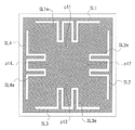
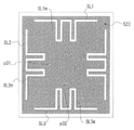
- the figure which shows the patch electrode which the antenna of this embodiment has.
- the perspective view which shows the appearance which the feeding part was attached to the circuit board.
- Block diagram of power supply and receiver. The figure which shows 2 feeding patch electrodes as a reference example.
- the figure which shows the patch electrode with 2 feeding slots which becomes a reference example. 2 Block diagram of the feeding circuit corresponding to the patch electrode with feeding slot.
- the block diagram which showed the other modification of the feeding circuit An exploded view of a composite antenna device equipped with antennas of other frequency bands in addition to the antenna of the satellite positioning system.
- the figure which visualized the state of the position information calculated when the vehicle equipped with the 2 feeding 2 resonance type antenna travels on the general road of the 1st area where the elevated road is in the zenith direction.
- a diagram that visualizes the state of position information calculated when a vehicle equipped with a 4-feed power 2-resonance type antenna travels on a general road in the first area where an elevated road is located in the zenith direction.
- the figure which visualized the state of the position information calculated when the vehicle equipped with the 2 feeding 2 resonance type antenna travels on the general road of the 2nd area where the elevated road is in the zenith direction.
- a diagram that visualizes the state of position information calculated when a vehicle equipped with a 4-feed power 2-resonance type antenna travels on a general road in a second area where an elevated road is located in the zenith direction.
- the present invention is applied to two frequency bands of GNSS (Global Navigation Satellite System) L1 band (1560 MHz to 1605 MHz) and GNSS L5 band (1150 MHz to 1210 MHz), or GNSS L1 band and GNSS L2 band (1197 MHz to).
- GNSS Global Navigation Satellite System
- L1 band 1560 MHz to 1605 MHz
- GNSS L5 band (1150 MHz to 1210 MHz
- GNSS L1 band and GNSS L2 band (1197 MHz to.
- the X-axis represents the length direction of the antenna
- the Y-axis represents the width direction of the antenna
- the Z-axis represents the zenith (vertically upward) direction of the antenna.
- the + Z axis direction is called “upper”, “upper”, “zenith” or “zenith direction”, and viewing the antenna from above is “top view”, and viewing the antenna from the Y axis is "side view”. May be written as.
- FIG. 1 shows an example of the component structure of the antenna of this embodiment.
- FIG. 1 is an exploded assembly view of the antenna 1.
- the antenna 1 is configured by accommodating a GNSS substrate assembly 12 airtightly and watertightly sealed with a packing 11 which is a shock absorber in an antenna case 10.
- the antenna case 10 is a radio wave transmitting housing composed of a top cover 10a and a base cover 10b.
- the top cover 10a is a bottomed cylindrical hard resin box, for example, a plastic box, which has a slightly rounded side portion and a square-shaped opening, and whose upper bottom portion is substantially square, and has an opening 4 of the top cover 10a.
- the two corners are evenly cut out. Further, screw holes corresponding to the screws 101 are threaded at the inner ends of the corners.
- the base cover 10b is a substantially square annular body, and the four corners are formed with protrusions 111 which are used for positioning with the top cover 10a and have holes through which the screws 101 are formed.
- the protrusion 111 is formed into a shape and size that seals the four corners of the top cover 10a when the base cover 10b is covered with the top cover 10a.
- a rib 112 for supporting the GNSS substrate assembly 12 is formed inside the four sides between the corners of the base cover 10b, and a cable guide 113 having a recess is formed on one side.
- the recess of the cable guide 113 is formed with a diameter equal to or smaller than the outer diameter of the power supply cable 124 described later. That is, it is molded so as to push and hold the power feeding cable 124.
- the GNSS substrate assembly 12 includes a circuit board 121 made of a thin insulating plate having front and back surfaces, a dielectric 122 installed almost in the center of the surface of the circuit board 121, and a patch electrode 123 attached to the surface of the dielectric 122. It is composed of a power supply cable 124 and a packing 11 made of a soft insulator such as rubber or silicon.
- a feeding portion including four board-side feeding terminals is formed on the back surface of the circuit board 121.
- This feeding unit will be described in detail later.
- One end of the power feeding cable 124 is electrically connected to the output portion of the feeding portion, and the other end is supported by the cable guide 113 of the base cover 10b and exposed to the outside of the antenna case 10. Further, one end of the power feeding cable 124 is maintained in airtightness and watertightness by the packing 11.
- the GNSS substrate assembly 12 is not limited to this shape.
- the mounting tape 13 has four corners cut out inward in an arc shape for allowing the screw 101 to penetrate through the hole of the protrusion 111 of the base cover 10b, and is attached to the back surface of the base cover 10b.
- the patch electrode 123 is a square metal plate substantially parallel to a ground conductor (for example, a vehicle roof), and is fixed slightly inward from the outer periphery of the surface of the dielectric 122.
- a structural example of the patch electrode 123 is shown in FIG. In the example of FIG. 2, the patch electrode 123 has four electrodes corresponding to one-to-one with the four substrate-side feeding terminals of the circuit board 121 at equidistant, equidistant, and point-symmetrical positions from the center point. Side feeding terminals p11, p12, p13, p14 are formed.
- the distance between the center point of the patch electrode 123 and the positions of the feeding terminals p11, p12, p13, and p14 on each electrode side is set to a distance at which the impedance of the patch electrode 123 can be matched (for example, 50 ohms) in the frequency band used.
- the patch electrode 123 has four slots SL1, SL2, SL3, and SL4 formed along each side of the square on the inside of the outer circumference thereof and on the outside of the feeding terminals p11, p12, p13, and p14 on the electrode side.
- Slot refers to the part where the metal plate is cut out.
- Each slot SL1, SL2, SL3, SL4 is axisymmetric with respect to the axis of symmetry passing through the center point of the patch electrode 123, and is located point-symmetrically with respect to the center point.
- the mianda (meandering) portions SL1m, SL2m, SL3m, and SL4m are formed at substantially intermediate positions of the straight line portions parallel to each side.
- the electrode-side feeding terminals p11, p12, p13, and p14 are formed at substantially the center of the nearest meandering portions SL1m, SL2m, SL3m, and SL4m.
- the meander portions SL1m, SL2m, SL3m, and SL4m are formed in order to make the electric length longer and the transmission / reception frequency lower than in the case without them. Therefore, by appropriately adjusting the sizes of the meanders SL1m, SL2m, SL3m, and SL4m after or before manufacturing, it is possible to fine-tune the transmit / receive frequency, increase the degree of freedom in design, and flexibly adjust the required transmission / reception band. It becomes possible to correspond to.
- One of the features of the antenna 1 of the present embodiment is that there is a patch electrode 123 in which four slots SL1, SL2, SL3, and SL4 matching the resonance conditions of a desired frequency are formed, and the four electrode-side feeding terminals p11, One p12, p13, and p14 exist at equal distances from the center point of the patch electrode 123, and the feeding phases (phases at the time of feeding, the same hereinafter the same) at the feeding terminals p11, p12, p13, and p14 on each electrode side are adjacent to each other. This is a point that is 90 degrees different from the feeding phases of the other electrode-side feeding terminals p11, p12, p13, and p14.
- the patch electrode 123 has an antenna operation for transmitting and receiving radio waves having a frequency satisfying the resonance condition due to the length of one side of the square and the dielectric constant of the dielectric 122, and the slots SL1, SL2, SL3, SL4, and the meander portion SL1m.
- the slot operation for transmitting and receiving radio waves having a frequency satisfying the resonance condition in consideration of the electric lengths of SL2m, SL3m, and SL4m is performed. That is, a "two resonance" operation is performed.
- the frequency that satisfies the resonance condition is a frequency in which the electrical length determined by the length of one side of the patch electrode 123 and the dielectric constant of the dielectric 122 is approximately 1/2 wavelength (and its integral multiple) in the antenna operation.
- the electric length determined by the total lengths of the meander portions SL1m, SL2m, SL3m, SL4m and the slots SL1, SL2, SL3, SL4 and the dielectric constant of the dielectric 122 is approximately 1/2 wavelength (and an integral multiple thereof). It is a frequency.
- the total length of the meander portion SL1m, SL2m, SL3m, SL4m and the slots SL1, SL2, SL3, SL4 is, for example, the length of the edge from one end to the other end of the slot and the edge from one end to the other end of the meander portion.
- the radio waves received by the patch electrode are circularly polarized because the four-point power supply is performed while shifting the phase of 90 degrees between the adjacent electrode side power supply terminals with equal amplitude. Become. When the phase shift is clockwise, it is right-handed circularly polarized wave, and when it is counterclockwise, it is left-handed circularly polarized wave. That is, according to the present embodiment, it becomes easy to realize reception of circularly polarized waves in two frequency bands of GNSS (for example, L1 band and L5 band, or L1 band and L2 band) with one antenna 1.
- GNSS for example, L1 band and L5 band, or L1 band and L2 band
- a slot having a meander portion is provided along each side of the square of the patch electrode, but the slot is a line with respect to the axis of symmetry passing through the center point of the patch electrode 123.
- any shape for example, a shape without a meander portion
- it may be (the place where it was).
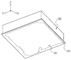
- FIG. 3 is a perspective view showing a state in which the feeding unit 20 is provided on the back surface of the circuit board 121.
- the feeding unit 20 is composed of a distributed constant line (conductor pattern group) printed on the back surface of the circuit board 121 and a lumped constant circuit including a passive element.
- the feeding unit 20 is composed of a feeding circuit 20a and an LNA (low noise amplifier), which are composed of four board-side feeding terminals, which will be described later, four matching circuits, six phase mixers, and two mixers.
- the feeding circuit 20a may be entirely composed of distributed constant lines.
- FIG. 4 shows the conductor pattern of the feeding unit 20.
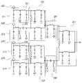
- FIG. 5 shows the feeding circuit 20a of the feeding section 20 shown in FIG. 4 by an equivalent circuit
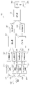
- FIG. 6 is a block diagram showing the feeding section 20 shown in FIG. 4 and the receiver 271 connected to the feeding section 20. Is. For convenience, the corresponding parts are designated by the same reference numerals.
- the configuration of the feeding unit 20 in the present embodiment will be described by integrating FIGS. 4, 5 and 6.
- the feeding unit 20 has four substrate-side feeding terminals p21, p22, p23 at the same positions of the feeding circuit 20 in the position of the four electrode-side feeding terminals p11, p12, p13, p14 formed on the patch electrode 123 and the top view. , P24 are formed.
- the nearest electrode side power supply terminal p11 and board side power supply terminal p21, electrode side power supply terminal p12 and board side power supply terminal p22, electrode side power supply terminal p13 and board side power supply terminal p23, electrode side power supply terminal p14 and board side power supply terminal p24 Each is directly conductively connected with a conductive pin or the like.
- the four board-side power supply terminals p21, p22, p23, and p24 have matching circuits 211,212,213,214 connected one-to-one for each corresponding line.
- the matching circuits 211,212,213,214 are circuits that perform impedance matching between the patch electrode 123 and the feeding unit 20, and all four circuits are lumped constant circuits with the same shape and area of conductor pattern and arrangement. It is configured.
- the matching circuit 211 has a phase shifter of +45 degrees
- the matching circuit 212 has a phase shift of ⁇ 45 degrees
- the matching circuit 213 has a phase shifter of +45 degrees.
- a phase detector 224 that performs a phase shift of ⁇ 45 degrees is connected to the circuit 214, respectively.
- Each of the matching circuits 211,212,213,214 performs impedance matching with respect to the received signal (power) divided into four equal parts by the patch electrode 123, and outputs the impedance to each phase device 221,222, 223, 224 in the subsequent stage.
- the phase detector 221 performs a phase shift of +45 degrees with respect to the received signal (power) output from the matching circuit 211, and outputs the phase shift to the mixer 231 in the subsequent stage.
- the phase detector 222 performs a phase shift of ⁇ 45 degrees with respect to the received signal (power) output from the matching circuit 212, and outputs the phase shift to the mixer 231 in the subsequent stage.
- the phase detector 223 performs a phase shift of +45 degrees with respect to the received signal (power) output from the matching circuit 213, and outputs the phase shift to the mixer 232 in the subsequent stage.
- the phase detector 224 performs a phase shift of ⁇ 45 degrees with respect to the received signal (power) output from the matching circuit 214, and outputs the phase shift to the mixer 232 in the subsequent stage.
- each phase device 221,222, 223, 224 is a ⁇ -type circuit in this example, and its cutoff frequency (cutoff frequency) is an arbitrary frequency in the GNSS frequency band. In this example, the frequency is set to be near the band edge of the GNSS frequency band.
- the phase detectors 221,222, 223, 224 may use either a high-pass filter or a low-pass filter, or a T-type circuit.
- the phase detectors 211,222,223,224 in this embodiment correspond to the first phase circuit.
- the mixer 231 inputs two received signals (electric power) output from the phase device 221 and the phase device 222, and combines them into one. Further, the mixer 232 inputs two received signals (electric power) output from the phase device 223 and the phase device 224, and combines them into one.
- circuit as shown in FIG. 5, it is composed of two ⁇ -type circuits and a resistor.
- the ⁇ -type circuits are connected in parallel with each other, and a resistor is connected between the input terminals of the ⁇ -type circuit.
- the cutoff frequency (cutoff frequency) of the ⁇ -type circuit is an arbitrary frequency in the GNSS frequency band, but in this example, it is set to a frequency near the band edge of the GNSS frequency band.
- the ⁇ -type circuit either a high-pass filter or a low-pass filter, or a T-type circuit may be used.
- the mixers 231 and 232 of the present embodiment correspond to the first mixing circuit.
- the output of the mixer 231 is input to the phase detector 241. Further, the output of the mixer 232 is input to the phase detector 242.
- the phase detector 241 performs a phase shift of the input received signal (power) by +90 degrees and outputs it to the mixer 251 in the subsequent stage.
- the phase detector 242 performs a phase shift of the input received signal (power) by ⁇ 90 degrees and outputs the input signal (power) to the mixer 251 in the subsequent stage.
- the mixer 251 inputs the received signals (electric power) output from the phase device 241 and the phase device 242, synthesizes these received signals (electric power), and outputs them to the LNA 261.
- the LNA 261 amplifies the combined received signal (power) at a predetermined amplification factor and outputs it to the receiver 271 in the subsequent stage.
- the mixers 231, 232, 251 are, for example, Wilkinson dividers.
- the phase detectors 241,242 of the present embodiment correspond to the second phase circuit, and the mixer 251 corresponds to the second mixing circuit.
- the receiver 271 has a position information processing circuit that extracts a digital signal from the received signal (electric power) output from the power feeding unit 20 and calculates the current position of the moving object in real time based on the extracted digital signal.
- a position calculation algorithm is incorporated in the position information processing circuit, and time information and current position information are output.
- the receiver 271 may be provided on the circuit board 121, or may be provided on another circuit board outside the antenna case 10.
- the antenna 1 and the receiver 271 having a position information processing circuit form an information processing device that calculates the position information of a moving body such as a vehicle to which the antenna 1 is attached.
- the antenna characteristics of the antenna 1 of the present embodiment configured as described above will be described.
- a simulator was used to analyze the antenna characteristics, and a simulation was performed using a ground conductor with a diameter of 15 cm.
- An antenna having an electrode 523 will be described.
- Reference example The electrodes 323, 423, and 523 have the same material, shape, and outer peripheral size as the patch electrodes of the present embodiment shown in FIG.
- the patch electrode 523 is the same as the patch electrode 123 shown in FIG.
- Reference example electrode 323 and 523 of 2 feeding are conductively connected to the feeding circuit 30 of 2 feeding shown in FIG. 9, and reference example electrode 423 of 4 feeding is electrically connected to the feeding circuit 20a shown in FIGS. 4, 5 and 6. Shall be.
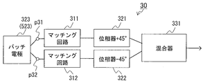
- the feeding circuit 30 in FIG. 9 outputs the received signal (power) distributed in two by the antenna to the phase detectors 321 and 322 after impedance matching is performed by the matching circuits 311, 312.
- the figure shows that the phase devices 321 and 322 shift the phases of the received signals (electric power) from the matching circuits 311, 312 in the opposite directions by 45 degrees, and the mixer 331 synthesizes these received signals (electric power). It is different from the power supply circuit 20a shown in 3, 4, 5, and 6.
- the antenna having the reference example electrode 323 is "2 feeding"
- the antenna having the reference example electrode 423 is "4 feeding”
- the antenna having the reference example electrode 523 is "2 feeding 2 resonance”.
- the antenna 1 having the patch electrode 123 may be abbreviated as "4 feeding 2 resonance".
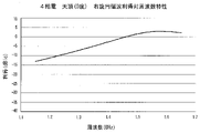
- FIG. 10A is a characteristic diagram of the right-handed circular polarization gain vs. frequency of the zenith (0 degree) in 2 feeds and 4 feeds, the vertical axis is the gain (dBic), and the horizontal axis is the frequency band (GHz). .. "Heaven (0 degree)" means the direction of the Z axis.
- the size of the patch electrode and the height from the ground conductor are the same as those of 2 feeds, but the gain is higher over the entire GNSS frequency band, and the maximum gain and the minimum gain in the GNSS frequency band. The difference with is small. That is, it can be seen that the wide band can be achieved by 4 power feedings.
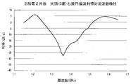
- 11A is a characteristic diagram of the right-handed circular polarization gain vs. frequency of the zenith (0 degree) of the zenith (0 degree) of 2 feeding 2 resonances and 4 feeding 2 resonances, and the vertical axis and the horizontal axis are the same as those of FIGS. 10A and 10B. be. Due to the influence of slots SL1, SL2, SL3, SL4, GNSS L1 band (1560MHz to 1605MHz), GNSS L5 band (1150MHz to 1210MHz), and GNSS L2 band (1197MHz to 1260MHz) can be obtained. However, in the case of 4-feeding and 2-resonance as in the present embodiment, the decrease in gain in the vicinity of each band is gradual. That is, it can be seen that even in the case of 2 resonances, a wide band can be achieved by 4 power feedings.
- FIG. 12A is an axial ratio vs. frequency characteristic diagram of the zenith (0 degree) of 2 feeds and 4 feeds, the vertical axis represents the axial ratio (dB), and the horizontal axis represents the frequency band (GHz).
- the axial ratio (dB) near the L1 band and some other frequencies decreases, but in the case of 4 feeding, the axial ratio is dramatic not only in the GNSS frequency band of the L5 band but also in the entire frequency band. It can be seen that it is improved.
- FIG. 13A is an axis ratio vs. frequency characteristic diagram of 2 feeding 2 resonances and FIG. 13B is a 4 feeding 2 resonances, and the vertical axis and the horizontal axis are the same as those of FIGS. 12A and 12B.
- the influence of slots SL1, SL2, SL3, SL4 is too large, and the axial ratio is 1 (dB) or more in all bands of GNSS L1 band, GNSS L5 band, and GNSS L2 band.
- 4 feeds and 2 resonances almost the same characteristics as in FIG. 12B are obtained. That is, it can be seen that the slots SL1, SL2, SL3, and SL4 are hardly affected.
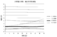
- FIG. 14A is an axis ratio to elevation angle characteristic diagram of 2 feeds and 4 feeds, the vertical axis represents the axis ratio (dB), and the horizontal axis represents the elevation angle (the angle from the zenith 0 degrees toward the horizontal plane).
- the frequencies selected were 1.55 GHz and 1.61 GHz. This is in consideration of the L1 band of GNSS.
- the axial ratio (dB) is not improved at any elevation angle at 1.61 GHz.
- the axial ratio is 1 dB or less from an elevation angle of around 30 degrees, but remains 0.7 dB or more even at around 45 degrees.
- the axial ratio is almost 0 dB up to an elevation angle of around 15 degrees, and the axial ratio exceeds 1 dB from around 40 degrees. That is, it can be seen that the axial ratio is improved by feeding 4 feeds.
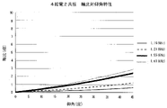
- FIG. 15A is an axis ratio vs. elevation characteristic diagram of 2 feeding 2 resonances and FIG. 15B is a 4 feeding 2 resonances, and the vertical axis and the horizontal axis are the same as those of FIGS. 14A and 14B.
- 1.16 GHz and 1.21 GHz were selected in addition to 1.55 GHz and 1.61 GHz. These frequencies take into account the L5 band of GNSS, the L1 band of GNSS, and the L2 band of GNSS.
- the axial ratio does not become 1 dB or less at any elevation angle, and in particular, at 1.21 GHz, the axial ratio exceeds 4 dB even if the elevation angle is 0 degrees.
- the elevation angle is 0 degrees and the axial ratio is about 2 dB, and the axial ratio increases as the elevation angle increases. Therefore, in the case of two feeding and two resonances, it is difficult to acquire accurate position information from the received signal in the L2 band of GNSS and the L1 band of GNSS.
- the axial ratio is near 0 dB, and especially at 1.16 GHz, the axial ratio is about 0.6 even if the elevation angle exceeds 45 degrees. It can be seen that the axial ratio is dramatically improved.
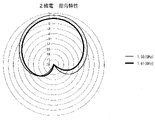
- FIG. 16A is a directivity diagram in a vertical plane with respect to right-handed circular polarization in two feeding and FIG. 16B is a four feeding.
- the zenith (0 degree) is above the Z-axis perpendicular to the ground conductor and passing through the center of the patch electrodes 323 and 423, that is, directly above the patch electrodes 323 and 423 and in the direction of 90 degrees to the right. It is the Y-axis, and the right-handed rotation of 270 degrees (left-handed rotation of 90 degrees) is the X-axis.
- the concentric circles represent the gain (dBic).
- As the frequency 1.55 GHz and 1.61 GHz are selected. It can be seen that in the case of 2 feeding, the directivity varies depending on the frequency, but in the case of 4 feeding, the directivity is directed toward the zenith regardless of the frequency.
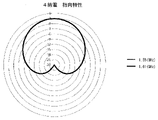
- FIG. 17A is a directivity diagram of 2 feeding 2 resonances and FIG. 17B is a directivity characteristic diagram of 4 feeding 2 resonances, and the contents of the graph are the same as those of FIGS. 16A and 16B.
- the frequencies are 1.55 GHz, 1.61 GHz, 1.16 GHz, and 1.21 GHz. It can be seen that the directivity varies depending on the frequency for both the 2-feed 2-resonance and the 4-feed 2-resonance, but the degree of variation is smaller for the 4-feed 2-resonance.
- the above description shows the characteristics when the LNA 261 is not arranged after the feeding circuit 20a, but even when the LNA 261 is arranged after the feeding circuit 20a, the gain is only changed by the LNA 261 and the characteristics themselves are not changed. ..
- the LNA261 may change the top loss of the antenna 1, that is, the power passing loss from the patch electrode 123 to the first stage amplifier (LNA261 in this example) depending on the arrangement position.
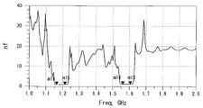
- FIGS. 18A to 18C are graphs for comparing the characteristics of the noise figure over the GNSS frequency band.
- FIG. 18A is a characteristic example in the case of the arrangement of the present embodiment. The arrangement example in this case is called the current example.
- FIG. 18B is a characteristic example when two LNA261s are arranged in the front stage of the mixers 231 and 232 of the first stage. Such an arrangement is referred to as a modification 1.
- FIG. 18C is a characteristic example when the LNA 261 is arranged in the front stage of the second stage mixer 251. Such an arrangement example is referred to as a modification 2.
- the vertical axis is the noise figure (nf) and the horizontal axis is the GNSS frequency (GHz).
- the measurement points are 1.615 GHz for m13, 1.560 GHz for m14, 1.215 GHz for m15, and 1.165 GHz for m16.
- the noise figure is 1.220 at the measurement point of m13, 1.170 at the measurement point of m14, 0.978 at the measurement point of m15, and 0.978 at the measurement point of m16. It is 0.965.
- the noise figure is 0.843 at the measurement point of m13, 0.788 at the measurement point of m14, 0.737 at the measurement point of m15, and 0 at the measurement point of m16. .747.
- the noise figure is 0.866 at the measurement point of m13, 0.825 at the measurement point of m14, 0.820 at the measurement point of m15, and 0.832 at the measurement point of m16. be.
- the noise figure of the current example is 1 at the measurement points of m13 and m14 and 1.2 at the measurement points of m15 and m16
- the modified example 1 0.8, m15 and m16 are measured at the measurement points of m13 and m24. It is improved to 0.7 at the measurement point of.
- the measurement points of m13 are 0.9, and the measurement points of m14, m25, and m26 are improved to 0.8.
- the total noise figure of the antenna 1 can be improved by arranging the LNA261 at a position as close as possible to the patch electrode 123, that is, in front of the phase detectors 221 to 224, 241,242 and the mixers 231,232,251. It turned out that it could be done.
- the power supply circuit 20a can be implemented in various forms other than those in FIGS. 4, 5, and 6.
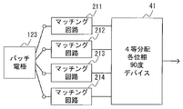
- FIG. 19 shows an example in which one 4-equal distribution phase 90-degree device 41, which combines the functions of the phase detectors 221 to 224, 241,242 and the mixers 231,232,251 shown in FIG. 6, is used. Is. By using this quaternary distribution 90-degree phase device 41, the antenna 1 can be made smaller and lighter.
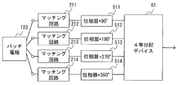
- phase detector 511 that outputs the input signal by shifting the phase by +90 degrees
- phase detector 512 that outputs by shifting by +180 degrees
- the phase detector 513 for output and the phase detector 514 for output after shifting by +360 degrees are installed, and the quadrant device 61 is installed in place of the mixers 231,232,251 and the phase detectors 241,242. Since the mixers 231, 232, and 251 are not used, a smaller and simpler power supply circuit can be realized.
- the phase of the input signal is changed to two 3 dB couplers 71, 72 instead of the phase detectors 221 to 224 and the mixers 231 and 232 shown in FIG. 6, and the phase detectors 241,242 and the mixer 251.
- One phase detector 81 that shifts by 90 degrees and a 3 dB coupler 91 are installed.
- Each 3 dB coupler 71, 72, 91 is terminated at 50 ohms, respectively.
- the 3dB coupler 71, 72, 91 may be a mixer, but a commercially available general-purpose coupler which is a discrete component can also be used.
- the antenna 1 of the present embodiment can be mounted on a moving body such as a robot or a drone by itself, but in recent years, it has also been used in an in-vehicle antenna device in which antenna portions of various frequency bands are mixedly mounted in one case. It can be used.
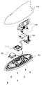
- FIG. 22 is an exploded assembly view of an in-vehicle composite antenna device equipped with the antenna 1 of the present embodiment.
- This composite antenna device includes an antenna 1, a flat antenna 102 in another frequency band, and a pole-shaped antenna 103 for digital television broadcasting on an antenna base 10b'which is airtightly and watertightly sealed by an antenna cover 10a'. It is configured to accommodate the stereoscopic antenna 104 for AM / FM. Since the antenna 1 has directivity in the zenith direction and the axial ratio in the zenith direction is significantly improved as compared with the conventional antennas, the planar antennas 102, 103, 104 in other frequency bands are in close proximity to each other. Even if they are arranged, at least in the GNSS frequency band, the signal for calculating the position information can be accurately received.
- a reference example antenna having a configuration shown in FIGS. 2 and 6 having a 4-feed supply 2 resonance (equipped with a receiver 271) and an antenna 1 having a configuration shown in FIGS. 8 and 9 having a 2-feed supply 2 resonance (equipped with a receiver 271) is used.
- the demonstration experiment of the position accuracy comparison that was performed will be described.
- the demonstration experiment was conducted as follows. First, a display device for displaying the position information output by the receiver 271 of each antenna (antenna 1 and the reference example antenna) was connected to the receiver 271 and mounted on the vehicle. The position information of the vehicle when driving on a road where the reception environment of radio waves is not good was calculated, and the calculated position information of the vehicle was displayed on the display device together with a map.
- the road on which the vehicle travels is a general road that exists directly under the elevated toll road, that is, a general road that has an elevated toll road in the direction of the zenith of each antenna.
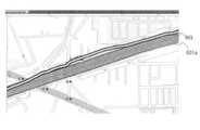
- FIG. 23 is a screen showing a reference example antenna traveling position (traveling locus consisting of a plurality of position information calculated as the vehicle travels) 601 when traveling on a general road in the first region. .. It was confirmed that the calculated traveling position 601 of the vehicle was affected by the elevated toll road 601a and showed a position significantly deviated to the left from the actual general road on the map.
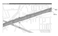
- FIG. 24 is a screen displaying the traveling position 602 by the antenna 1 when traveling on the same general road. It was confirmed that the traveling position 602 of the vehicle detected by the antenna 1 shows the correct position on the map without deviating from the actual general road, regardless of the existence of the elevated toll road.
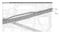
- FIG. 25 is a screen showing the traveling position 701 of the vehicle by the reference example antenna when traveling on the general road in the second region different from the first region. It was confirmed that the calculated traveling position 701 of the vehicle was affected by the elevated toll road 701a and showed a large position on the map to the left of the actual general road.
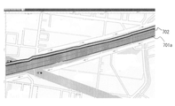
- FIG. 26 is a screen displaying the traveling position 702 by the antenna 1 when traveling on the same general road. It was confirmed that the traveling position 702 of the vehicle calculated by the antenna 1 indicates the correct position on the map without deviating from the actual general road.
- the antenna 1 of the present embodiment is the first reference example antenna having two feedings and two resonances even when traveling on a road having an obstacle in either the first region or the second region in the zenith direction. It was demonstrated that the position information can be calculated with higher accuracy than that.
- a dielectric, a patch electrode provided on the dielectric, and a circuit board are provided, the patch electrode has four feeding terminals, and the circuit board has each of the four feeding terminals.
- the mixed circuit a board-side feeding terminal that conducts one-to-one, a phase circuit that phase-shifts the signal output from the board-side feeding terminal, a mixing circuit that mixes the phase-shifted signal in the phase circuit, and the mixing circuit.
- An antenna provided with an amplifier circuit that amplifies the mixed signal.
- the antenna characteristics in the zenith direction are significantly improved as compared with the antenna having the patch electrode shown in FIGS. 7A and 7B or the patch electrode shown in FIG. 8, for example. Therefore, as is clear from the above-mentioned demonstration experiment, the position accuracy of the moving body equipped with this antenna is remarkably improved.
- each of the four power supply terminals and the corresponding conduction portion in the substrate side power supply terminal face each other. Antenna to do.
- each of the four feeding terminals and the corresponding conduction portion in the feeding terminal on the substrate side are conductively connected at the shortest distance determined by the thickness of the dielectric, so that they are less susceptible to external influences.
- the antenna having this configuration transmits and receives radio waves with a frequency that satisfies the resonance condition due to the size of the patch electrode and the dielectric constant of the dielectric, and radio waves with a frequency that satisfies the resonance condition considering the electrical length of the slot. Perform slot operation. That is, "two resonance" operation becomes possible.
- the phase circuit includes a first phase circuit and a second phase circuit
- the mixing circuit includes a first mixing circuit and a second mixing circuit
- the first phase circuit is fed to the substrate side.
- the second phase circuit is arranged after the terminal, the second phase circuit is arranged after the first phase circuit, and the first mixing circuit is arranged after the first phase circuit and before the second phase circuit.
- the second mixing circuit is arranged after the second phase circuit, and the amplifier circuit is arranged after the second mixing circuit.
- the first phase circuit has, for example, two phase detectors that phase shift the input signal in the positive direction by 45 degrees and two phase detectors that phase shift the input signal in the negative direction by 45 degrees.
- the second phase circuit has, for example, a phase device that phase-shifts the input signal 90 degrees in the positive direction and a phase device that phase-shifts the input signal 90 degrees in the negative direction.
- the mixing circuit is a Wilkinson divider.
- the main part of the circuit can be realized by a group of conductor patterns printed on a substrate, and mass production of antennas becomes easy.
- the amplifier circuit is an antenna provided in front of the mixing circuit.
- the phase circuit includes a first phase circuit and a second phase circuit
- the mixing circuit includes a first mixing circuit and a second mixing circuit
- the first phase circuit includes the first phase circuit.
- the second phase circuit is arranged after the first phase circuit
- the first mixing circuit is arranged after the first phase circuit
- the second phase circuit is arranged after the first phase circuit.
- the second mixing circuit is arranged in the rear stage of the second phase circuit
- the amplifier circuit is arranged in the front stage of the first mixing circuit or the second mixing circuit.
- An information processing device mounted on a mobile body comprising one of the above antennas and a position information processing circuit that calculates position information of the antenna based on a signal output from the antenna.
- Information processing device According to the information processing device having this configuration, for example, the position information of the automatically driven vehicle can be calculated with high accuracy.
- a first antenna of a satellite positioning system having a patch electrode having four feeding terminals and a circuit board that processes a signal received from the patch electrode, and a signal having a frequency band different from that of the first antenna.
- a composite antenna including a second antenna for receiving, an antenna base on which the first antenna and the second antenna are placed, and an antenna case for accommodating the first antenna and the second antenna together with the antenna base.
- the device can be miniaturized and space-saving by accommodating the first antenna corresponding to multiple frequencies in the same accommodation space together with the other antenna (second antenna).
- Another other that includes a dielectric, a patch electrode provided on the dielectric, and four feeding terminals provided on the patch electrode, and the feeding phases of the four feeding terminals are adjacent to each other. It differs from the feeding phase of the feeding terminal by 90 degrees, and each of them is directly conductive to the board-side feeding terminal provided on the circuit board side that processes the signal received from the patch electrode. It is possible to improve the axial ratio.
- the four slots in the patch electrode may each have a configuration of having the same shape having a meander portion. In such a configuration, the frequency satisfying the resonance condition can be adjusted in the slot, so that the degree of freedom in antenna design can be increased.
- the patch electrode 123 is formed with four electrode-side feeding terminals p11, p12, p13, and p14 at positions symmetrical with respect to the center point thereof, and the feeding portion 20 has four feeding terminals.
- Two power supply side power supply terminals p21, p22, p23, and p24 are provided.
- the antenna may have the following configuration.
- a dielectric, a patch electrode provided on the dielectric, and a circuit board are provided, and the patch electrode is formed with four feeding terminals point-symmetrically with respect to the center point thereof, and the circuit board is formed.
- the signals output from the four board-side power supply terminals that conduct one-to-one with each of the four power supply terminals and the signal output from the nearest board-side power supply terminal among the four board-side power supply terminals are adjacent to each other.
- the two first phase circuits that mix the signals output from the two adjacent first phase circuits of the four first phase circuits and the four first phase circuits that shift the phase by the same amount by reversing the shift direction.
- the mixing circuit the two second phase circuits that shift the phase of the signals output from the two first mixing circuits by the same amount by reversing the shift direction from the adjacent signals, and the two second phase circuits.
- An antenna provided with a second mixing circuit that mixes output signals.
- the four signals received by the patch electrode of the four-point feeding and input to the circuit board through the feeding terminal on the board side are opposite to the adjacent signals in the corresponding first phase circuit in the shift direction.
- the two are mixed in the first mixing circuit.
- the two mixed signals are further phase-shifted by the same amount with the adjacent signals in the second phase circuit in the opposite shift directions, and then mixed into one signal in the second mixing circuit.
- a phase difference of degrees (0 degrees) is generated, which appears as a phase difference of the four signals output from the feeding terminal as it is.
- One of the means for compensating for the phase difference between the signals is to phase-shift and mix the other signals so as to match the phase of one of the signals.
- the passing loss of the signal passes loss of electric power
- the amplitude difference between the two signals becomes extremely large, which may adversely affect the antenna characteristics, particularly the gain and the axial ratio, when these are mixed.
- the passing loss of the signal when phase-shifting in the four first phase circuits and the two second phase circuits in the subsequent stage is shifted to the adjacent signals so as to have the same magnitude in each line.
- the pass loss due to the phase shift is eliminated. Equal on each line.
- the amplitude of each signal after the phase shift becomes almost uniform regardless of the received frequency, and it is possible to suppress an unfavorable influence on the gain and the axial ratio. That is, it is possible to widen the band, suppress the variation in the directivity toward the zenith, and expand the elevation range in which the axial ratio is good.
Landscapes
- Engineering & Computer Science (AREA)
- Remote Sensing (AREA)
- Radar, Positioning & Navigation (AREA)
- Computer Networks & Wireless Communication (AREA)
- Physics & Mathematics (AREA)
- General Physics & Mathematics (AREA)
- Waveguide Aerials (AREA)
- Variable-Direction Aerials And Aerial Arrays (AREA)
Abstract
軸比に優れ、複数周波数帯に対応するアンテナを提供する。 本発明のアンテナは、パッチ電極を有する誘電体と給電部を有する回路基板とを備える。パッチ電極には、4つの電極側給電端子p11~p14が形成されている。給電回路には、4つの電極側給電端子p11~p14と導通接続する4つの基板側給電端子が形成されている。電極側給電端子p11~p14には、等振幅で90度ずつ位相シフトした受信信号(電力)が給電される。
Description
本発明は、車輌、ロボット、ドローンのような移動体に搭載可能なアンテナ、情報処理装置及び複合アンテナ装置に関する。
近年、ADAS(Advanced Driver-Assistance Systems,先進運転支援システム)のような車輌の自動運転の開発が急速に進められている。このような自動運転では、車輌に取り付けられる衛星測位システムのアンテナが受信する受信信号を用いて当該車輌の現時点の位置情報をできる限り迅速かつ正確に取得することが求められる。位置情報の取得精度を高める簡易な手段は、複数の人工衛星からの多周波数の信号をそれぞれの周波数に対応するアンテナが受信してそれぞれの受信信号を基に位置情報を算出することである。しかし、車載用のアンテナ装置の場合、多周波数の信号を受信するそれぞれのアンテナ以外にAM/FM帯など他の異なる周波数帯にも対応可能なアンテナ部も実装される。よって、多周波数の信号を受信するそれぞれのアンテナを同一の筐体内に設けると装置自体が大きくなり、車載用に適さなくなる。
このような課題に関し、本願出願人は、特許文献1において、正方形導体から成るパッチ電極に、2対のスロットが形成され、かつ2つの給電点が設けられたスロット付きアンテナを提案した。各スロットは、それぞれ同一形状及びサイズで、正方形導体の中心点に対して点対称に2対配置される。2つの給電点は正方形導体の中心からやや外側に偏心した位置に設けられ、それら2つの給電点に給電を行って円偏波の受信が効率的に行われる。
特許文献1に記載されたスロット付きアンテナは、正方形導体の外周寸法に従うアンテナ動作のほか、スロットの寸法に従うスロットアンテナ動作が可能となり、複数の人工衛星から送信される多周波の信号を1つのアンテナで受信することができる。また、ミアンダ形状をスロットに形成することで、アンテナ動作及びスロットアンテナ動作の受信帯域の設定の自由度を向上させ、要求される受信帯域への対応が容易となる。さらに、2点給電により円偏波の受信が効率的になることに加え、広い周波数帯域で軸比(Axial Ratio)を良好にすることができる。
車輌のような移動体は、移動中の姿勢が三次元で絶えず変化するのが一般的である。また、例えば、ADASのような車輌の自動運転における位置情報の精度向上の要求に応えるため、衛星測位システムのアンテナは、人工衛星からの信号を広い周波数帯で軸比がよく、また、広い仰角で軸比が良好なことが望ましい。さらに、車輌以外の移動体であるドローン等に関してもその位置情報の精度向上が求められている。つまり、例えば、車輌の自動運転やドローンの小型無人飛行機などの無人制御での移動体に関しては、これまで以上に位置精度の向上が求められていくこととなる。
本発明の主たる目的は、例えば、アンテナの受信信号に基づいて導出される移動体の位置精度のさらなる向上に貢献することにある。
本発明の一態様となるアンテナは、誘電体と、誘電体に設けられたパッチ電極及び回路基板と、を備え、パッチ電極は4つの給電端子を有し、回路基板には、4つの給電端子の各々と1対1に導通する基板側給電端子と、基板側給電端子から出力された信号を位相シフトする位相回路と、位相回路で位相シフトされた信号を混合する混合回路と、混合回路で混合された信号を増幅する増幅回路と、が設けられている。
本発明の他の一態様となる情報処理装置は、移動体に搭載される情報処理装置であって、少なくとも4つの給電端子を有するパッチ電極と、4つの給電端子の各々と1対1に導通する基板側給電端子、基板側給電端子から出力された信号を位相シフトする位相回路、位相回路で位相シフトされた信号を混合する混合回路、および混合回路で混合された信号を増幅する増幅回路と、を有する回路基板を備えたアンテナと、アンテナから出力される信号に基づいて前記移動体の位置情報を算出する位置情報処理回路と、を備える。
本発明の他の一態様となる複合アンテナ装置は、4つの給電端子を有するパッチ電極、前記パッチ電極からの受信信号を信号処理する回路基板と、を有する衛星測位システムの第1アンテナと、第1アンテナとは異なる周波数帯の信号を受信する第2アンテナと、第1アンテナと前記第2アンテナとを載置するアンテナベースと、前記アンテナベースと共に前記第1アンテナと前記第2アンテナと、を収容するアンテナケースと、を備える。
本発明によれば、1点給電もしくは2点給電と比較して、広仰角広周波数に軸比を改善して移動体の位置精度のさらなる向上の実現に貢献することができる。また、多周波数に対応したアンテナであるため、それぞれの周波数に対応する複数のアンテナを設ける必要がなく、省スペース化に寄与することができる。
以下、本発明を、GNSS(Global Navigation Satellite System)のL1バンド(1560MHz~1605MHz)とGNSSのL5バンド(1150MHz~1210MHz)の2周波数帯、あるいは、GNSSのL1バンドとGNSSのL2バンド(1197MHz~1260MHz)の2周波数帯を同時に受信可能な衛星測位システムのアンテナ(以下、単にアンテナと称する)に適用した場合を一例とし、その実施の形態を図面を参照して説明する。なお、本実施形態では、説明の便宜上、X軸、Y軸及びZ軸の直交三次元軸を図面上に記載する。X軸はアンテナの長さ方向、Y軸はアンテナの幅方向、Z軸はアンテナの天頂(鉛直上方)方向を表す。また、+Z軸方向を「上」、「上方」、「天頂」ないし「天頂方向」といい、上方からアンテナを視ることを「上面視」、Y軸からアンテナを視ることを「側面視」と表記する場合がある。
本実施形態のアンテナの部品構造例を図1に示す。図1は、アンテナ1の分解組立図である。図1を参照すると、アンテナ1は、アンテナケース10内に、緩衝体であるパッキン11で気密及び水密に封止されたGNSS基板アッセンブリ12を収容して構成される。
アンテナケース10は、トップカバー10aとベースカバー10bとで構成される電波透過性の筐体である。トップカバー10aは、若干の丸みを持つ側部と、正方形状の開口部とを有し、上底部が略正方形となる有底筒状の硬質樹脂箱、例えばプラスチック箱であり、開口部の4つの角部が均等に切り欠かれている。また、各角部の内端部には、それぞれネジ101に対応するネジ穴が螺刻されている。ベースカバー10bは略正方形の環状体であって、4つの角部には、トップカバー10aとの位置決めに用いると共にネジ101を貫通させる孔が形成された突起部111が形成されている。
この突起部111は、ベースカバー10bにトップカバー10aを被せたときに、トップカバー10aの4つの角部を封止する形状・サイズに成形されている。ベースカバー10bの角部間の4つの辺部の内側にはGNSS基板アッセンブリ12を支持するためのリブ112が形成され、1つの辺部には、窪みを有するケーブルガイド113が形成されている。ケーブルガイド113の窪みは、後述する給電ケーブル124の外径以下の径で成形されている。つまり、給電ケーブル124を押し込んで保持するように成形されている。
GNSS基板アッセンブリ12は、表裏面を有する薄い絶縁板から成る回路基板121と、回路基板121の表面のほぼ中央部に設置される誘電体122と、誘電体122の表面に取り付けられたパッチ電極123と、給電ケーブル124と、ゴム、シリコンなどの軟質絶縁体で構成されるパッキン11と、で構成される。
回路基板121の裏面には、4つの基板側給電端子を含む給電部が形成されている。この給電部については、後で詳しく説明する。給電ケーブル124の一端は給電部の出力部と導通接続されており、他端はベースカバー10bのケーブルガイド113に支持されてアンテナケース10の外部に露出する。また、給電ケーブル124の一端は、パッキン11によって気密性と水密性が保持されている。なお、GNSS基板アッセンブリ12は、この形状に限ることはない。取付テープ13は、ネジ101をベースカバー10bの突起部111の孔に貫通させるための4つの角部が内側に弧状に切り欠かれており、ベースカバー10bの裏面に貼り付けられている。
パッチ電極123は、地導体(例えば車輌ルーフ)と略平行となる正方形状の金属板であり、誘電体122の表面の外周から僅かに内側寄りに固着される。パッチ電極123の構造例を図2に示す。図2の例では、パッチ電極123には、その中心点から等距離、等間隔、かつ点対称となる位置に、回路基板121の4つの基板側給電端子と1対1に対応する4つの電極側給電端子p11,p12,p13,p14が形成されている。
パッチ電極123の中心点と各電極側給電端子p11,p12,p13,p14の位置との距離は、使用する周波数帯でパッチ電極123のインピーダンスの整合(例えば、50オーム)がとれる距離に設定される。
パッチ電極123の中心点と各電極側給電端子p11,p12,p13,p14の位置との距離は、使用する周波数帯でパッチ電極123のインピーダンスの整合(例えば、50オーム)がとれる距離に設定される。
パッチ電極123には、その外周の内側で、各電極側給電端子p11,p12,p13,p14に対しては外側に、正方形の各辺に沿って4つのスロットSL1、SL2、SL3、SL4が形成されている。「スロット」は金属板が切り欠かれた部分をいう。各スロットSL1、SL2、SL3、SL4は、パッチ電極123の中心点を通る対称軸に対して線対称で、かつ、中心点に対して点対称に位置する。
また、4つのスロットSL1、SL2、SL3、SL4のうち、各辺と平行となる直線部分の略中間位置にはミアンダ(蛇行)部SL1m、SL2m、SL3m、SL4mが形成されている。電極側給電端子p11,p12,p13,p14は、直近のミアンダ(蛇行)部SL1m、SL2m、SL3m、SL4mのほぼ中央部に形成されている。
ミアンダ部SL1m、SL2m、SL3m、SL4mは、それが無い場合よりも電気長を長くし、送受信周波数を低くするために形成される。そのため、ミアンダ部SL1m、SL2m、SL3m、SL4mのサイズを製造後又は製造前に適宜調整することで送受信可能周波数の微調整が可能になり、設計の自由度が増し、要求される送受信帯域に柔軟に対応可能となる。
本実施形態のアンテナ1の1つの特徴は、所望の周波数の共振条件に適合する4つのスロットSL1、SL2、SL3、SL4が形成されたパッチ電極123が存在し、4つの電極側給電端子p11,p12,p13,p14が、パッチ電極123の中心点から等距離で1つずつ存在し、各電極側給電端子p11,p12,p13,p14における給電位相(給電時の位相、以下同じ)が隣り合う他の電極側給電端子p11,p12,p13,p14の給電位相と90度ずつ異なっている点である。
そのため、パッチ電極123は、正方形の一辺の長さ及び誘電体122の誘電率に起因する共振条件を満たす周波数の電波を送受信するアンテナ動作と、スロットSL1、SL2、SL3、SL4、ミアンダ部SL1m、SL2m、SL3m、SL4mの電気長をも考慮した共振条件を満たす周波数の電波を送受信するスロット動作とを行う。つまり「2共振」動作を行う。
そのため、パッチ電極123は、正方形の一辺の長さ及び誘電体122の誘電率に起因する共振条件を満たす周波数の電波を送受信するアンテナ動作と、スロットSL1、SL2、SL3、SL4、ミアンダ部SL1m、SL2m、SL3m、SL4mの電気長をも考慮した共振条件を満たす周波数の電波を送受信するスロット動作とを行う。つまり「2共振」動作を行う。
共振条件を満たす周波数は、アンテナ動作においては、パッチ電極123の一辺の長さ及び誘電体122の誘電率から定まる電気長が略1/2波長(及びその整数倍)となる周波数である。スロット動作においては、ミアンダ部SL1m、SL2m、SL3m、SL4m及びスロットSL1、SL2、SL3、SL4の全長及び誘電体122の誘電率から定まる電気長が略1/2波長(及びその整数倍)となる周波数である。
なお、ミアンダ部SL1m、SL2m、SL3m、SL4m及びスロットSL1、SL2、SL3、SL4の全長は、例えば、スロットの一端から他端までの縁の長さ及びミアンダ部の一端から他端までの縁の長さである。
線対称及び点対称の位置で、等振幅で順次隣り合う電極側給電端子との間に90度の位相をシフトしながら4点給電を行うため、パッチ電極で受信される電波は円偏波となる。位相のシフトが右回りの場合は右旋円偏波となり、左回りの場合は左旋円偏波となる。
つまり、本実施形態によれば、GNSSの2周波数帯(例えばL1バンドとL5バンド、あるいは、L1バンドとL2バンド)の円偏波の受信を1つのアンテナ1で実現することが容易になる。
なお、ミアンダ部SL1m、SL2m、SL3m、SL4m及びスロットSL1、SL2、SL3、SL4の全長は、例えば、スロットの一端から他端までの縁の長さ及びミアンダ部の一端から他端までの縁の長さである。
線対称及び点対称の位置で、等振幅で順次隣り合う電極側給電端子との間に90度の位相をシフトしながら4点給電を行うため、パッチ電極で受信される電波は円偏波となる。位相のシフトが右回りの場合は右旋円偏波となり、左回りの場合は左旋円偏波となる。
つまり、本実施形態によれば、GNSSの2周波数帯(例えばL1バンドとL5バンド、あるいは、L1バンドとL2バンド)の円偏波の受信を1つのアンテナ1で実現することが容易になる。
なお、本実施形態では、パッチ電極の正方形の各辺に沿って、ミアンダ部を形成したスロットを設けたことについて説明したが、スロットは、パッチ電極123の中心点を通る対称軸に対して線対称で、かつ、中心点に対して点対称に位置していれば、いずれの形状(例えば、ミアンダ部を設けない形状)でも、いずれの箇所(例えば、パッチ電極の正方形の各角部に沿った箇所)でもよい。
次に、回路基板121に設けられる給電部20について説明する。
図3は、給電部20が回路基板121の裏面に設けられた様子を示す斜視図である。図3ではその詳細を省略しているが、給電部20は、回路基板121の裏面にプリント形成された分布定数線路(導体パターン群)と受動素子を含む集中定数回路で構成している。給電部20は、後述する4つの基板側給電端子、4つのマッチング回路、6つの位相器、ならびに2つの混合器と、で構成される給電回路20aとLNA(低雑音増幅器)と、で構成される。
なお、給電回路20aをすべて分布定数線路で構成してもよい。
図3は、給電部20が回路基板121の裏面に設けられた様子を示す斜視図である。図3ではその詳細を省略しているが、給電部20は、回路基板121の裏面にプリント形成された分布定数線路(導体パターン群)と受動素子を含む集中定数回路で構成している。給電部20は、後述する4つの基板側給電端子、4つのマッチング回路、6つの位相器、ならびに2つの混合器と、で構成される給電回路20aとLNA(低雑音増幅器)と、で構成される。
なお、給電回路20aをすべて分布定数線路で構成してもよい。
給電部20の導体パターンを図4に示す。図5は、図4に示した給電部20のうち給電回路20aを等価回路で示したものであり、図6は図4に示した給電部20とそれに接続されたレシーバ271とを示すブロック図である。便宜上、対応する部品については同一符号を付してある。以下、図4,5,6を総合して、本実施形態における給電部20の構成を説明する。
給電部20は、パッチ電極123に形成された4つの電極側給電端子p11,p12,p13,p14の位置と上面視で給電回路20の同じ位置に、4つの基板側給電端子p21,p22,p23,p24が形成されている。直近の電極側給電端子p11と基板側給電端子p21,電極側給電端子p12と基板側給電端子p22,電極側給電端子p13と基板側給電端子p23,電極側給電端子p14と基板側給電端子p24は、それぞれ導電ピン等でダイレクトに導通接続される。
4つの基板側給電端子p21,p22,p23,p24は、それぞれ対応する線路毎にマッチング回路211,212,213,214が1対1で導通接続されている。マッチング回路211,212,213,214は、パッチ電極123と給電部20との間のインピーダンス整合を行う回路であり、4つの回路がすべて同じ形状・面積の導体パターン及び配置関係で集中定数回路で構成されている。マッチング回路211には+45度の位相シフトを行う位相器221,マッチング回路212には-45度の位相シフトを行う位相器222,マッチング回路213には+45度の位相シフトを行う位相器223,マッチング回路214には-45度の位相シフトを行う位相器224が、それぞれ接続されている。なお、本実施形態ではマッチング回路211,212,213,214を用いた構成について説明するが、これらマッチング回路が無くても本発明の実施は可能である。
マッチング回路211,212,213,214の各々は、パッチ電極123によって4等分された受信信号(電力)に対しインピーダンス整合を行い、後段の各位相器221,222,223,224に出力する。位相器221は、マッチング回路211から出力された受信信号(電力)に対して+45度の位相シフトを行い、後段の混合器231に出力する。同様に、位相器222は、マッチング回路212から出力された受信信号(電力)に対して-45度の位相シフトを行い、後段の混合器231に出力する。位相器223は、マッチング回路213から出力された受信信号(電力)に対して+45度の位相シフトを行い、後段の混合器232に出力する。位相器224は、マッチング回路214から出力された受信信号(電力)に対して-45度の位相シフトを行い、後段の混合器232に出力する。
各位相器221,222,223,224は、図5に示されるように、本例ではπ型回路であり、そのカットオフ周波数(遮断周波数)は、GNSS周波数帯の任意の周波数であるが、本例ではGNSS周波数帯のバンドエッジ近傍となる周波数に設定されている。位相器221,222,223,224は、ハイパス、ローパスのいずれのフィルタ、あるいはT型回路を用いてもよい。なお、本実施形態における位相器221,222,223,224が第1位相回路に相当する。
混合器231は、位相器221と位相器222から出力された2つの受信信号(電力)を入力し、1つに合成する。また、混合器232は、位相器223と位相器224から出力された2つの受信信号(電力)を入力し、1つに合成する。回路的には、図5に示されるように、2つのπ型回路及び抵抗で構成される。π型回路は互いに並列に接続され、π型回路の入力端子間に抵抗が接続される。π型回路のカットオフ周波数(遮断周波数)は、GNSS周波数帯の任意の周波数であるが、本例ではGNSS周波数帯域のバンドエッジ近傍となる周波数に設定されている。π型回路は、ハイパス、ローパスのいずれのフィルタ、あるいは、T型回路を用いてもよい。なお、本実施形態の混合器231,232が第1混合回路に相当する。
混合器231の出力は、位相器241に入力される。また、混合器232の出力は、位相器242に入力される。位相器241は入力された受信信号(電力)を+90度の位相シフトを行い、後段の混合器251へ出力する。位相器242は入力された受信信号(電力)を-90度の位相シフトを行い、後段の混合器251へ出力する。混合器251は、位相器241と位相器242から出力された受信信号(電力)を入力し、これらの受信信号(電力)を合成してLNA261へ出力する。LNA261は、合成された受信信号(電力)を所定の増幅率で増幅して後段のレシーバ271へ出力する。混合器231,232,251は、例えば、ウィルキンソンデバイダーである。なお、本実施形態の位相器241,242が第2位相回路に相当し、混合器251が第2混合回路に相当する。
次にレシーバ271について説明する。レシーバ271は、給電部20から出力される受信信号(電力)からデジタル信号を抽出し、当該抽出されたデジタル信号に基づいて移動体の現在位置をリアルタイムに算出する位置情報処理回路を有する。位置情報処理回路には、位置算出アルゴリズムが組み込まれており、時刻情報と現在位置情報とを出力する。このレシーバ271は、回路基板121に設けてもよいが、アンテナケース10外の他の回路基板に設けてもよい。なお、このアンテナ1と位置情報処理回路を有するレシーバ271とで、アンテナ1が取り付けられた車輌などの移動体の位置情報を算出する情報処理装置が構成される。
[アンテナ特性]
以下、上記のように構成される本実施形態のアンテナ1のアンテナ特性について説明する。アンテナ特性の解析にはシミュレータを用い、直径15cmの地導体を用いてシミュレーションを行った。ここで、特徴別の特性比較のため、図7Aに示す2給電スロット無しの参照例電極323、図7Bに示す4給電スロット無しの参照例電極423、図8に示す2給電スロット付きの参照例電極523を有するアンテナについて説明する。
参照例電極323,423,523は、図2に示した本実施形態のパッチ電極と同じ材質・形状・外周サイズである。パッチ電極523は、電極側給電端子p31,p32が2つである点以外は、図2に示したパッチ電極123と同じである。2給電の参照例電極323,523は、図9に示す2給電の給電回路30に導通接続され、4給電の参照例電極423は、図4,5,6に示す給電回路20aに導通接続されるものとする。
以下、上記のように構成される本実施形態のアンテナ1のアンテナ特性について説明する。アンテナ特性の解析にはシミュレータを用い、直径15cmの地導体を用いてシミュレーションを行った。ここで、特徴別の特性比較のため、図7Aに示す2給電スロット無しの参照例電極323、図7Bに示す4給電スロット無しの参照例電極423、図8に示す2給電スロット付きの参照例電極523を有するアンテナについて説明する。
参照例電極323,423,523は、図2に示した本実施形態のパッチ電極と同じ材質・形状・外周サイズである。パッチ電極523は、電極側給電端子p31,p32が2つである点以外は、図2に示したパッチ電極123と同じである。2給電の参照例電極323,523は、図9に示す2給電の給電回路30に導通接続され、4給電の参照例電極423は、図4,5,6に示す給電回路20aに導通接続されるものとする。
図9における給電回路30は、アンテナで2分配された受信信号(電力)を、マッチング回路311,312でインピーダンス整合を行った後、位相器321,322に出力する。各位相器321,322は、マッチング回路311,312からの受信信号(電力)を互いに45度ずつ逆方向に位相をシフトさせ、混合器331がこれらの受信信号(電力)を合成する点が図3,4,5,6に示した給電回路20aと異なる。比較説明の便宜上、参照例電極323を有するアンテナを「2給電」、参照例電極423を有するアンテナを「4給電」、参照例電極523を有するアンテナを「2給電2共振」、本実施形態のパッチ電極123を有するアンテナ1を「4給電2共振」と略称する場合がある。
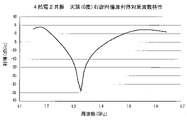
図10Aは2給電、図10Bは4給電における天頂(0度)の右旋円偏波利得対周波数の特性図であり、縦軸が利得(dBic)、横軸は周波数帯(GHz)である。「天頂(0度)」とはZ軸の方向をいう。4給電の場合は、2給電と比べてパッチ電極のサイズや地導体からの高さが同じでありながら、利得がGNSS周波数帯の全域にわたって高くなり、かつ、GNSS周波数帯における最大利得と最小利得との差が小さくなっている。つまり、4給電により広帯域化が図られることがわかる。
図11Aは2給電2共振、図11Bは4給電2共振の天頂(0度)の右旋円偏波利得対周波数の特性図であり、縦軸、横軸は図10A及び図10Bと同じである。スロットSL1,SL2,SL3,SL4の影響で、実用レベルの利得が得られるのは、GNSSのL1バンド(1560MHz~1605MHz)、GNSSのL5バンド(1150MHz~1210MHz)、GNSSのL2バンド(1197MHz~1260MHz)であるが、本実施形態のような4給電2共振の場合、各バンド付近での利得の低下が緩やかになっている。つまり、2共振の場合も4給電により広帯域化が図られることがわかる。
図12Aは2給電、図12Bは4給電の天頂(0度)の軸比対周波数特性図であり、縦軸は軸比(dB)、横軸は周波数帯(GHz)を表す。2給電の場合、L1バンド付近と一部の他の周波数の軸比(dB)が低下するが、4給電では、L5バンドのGNSS周波数帯だけでなく全体の周波数帯域にわたって、軸比が劇的に改善されることがわかる。
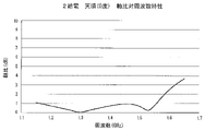
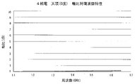
図13Aは2給電2共振、図13Bは4給電2共振の軸比対周波数特性図であり、縦軸、横軸は図12A及び図12Bと同じである。2給電2共振の場合、スロットSL1,SL2,SL3,SL4の影響があまりにも大きく、GNSSのL1バンド、GNSSのL5バンド、GNSSのL2バンドのすべてのバンドにおいても軸比が1(dB)以上となるが、4給電2共振では、図12Bとほぼ同じ特性が得られている。つまり、スロットSL1,SL2,SL3,SL4の影響を殆ど受けていないことがわかる。
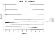
図14Aは2給電、図14Bは4給電の軸比対仰角特性図であり、縦軸は軸比(dB)、横軸は仰角(天頂0度から水平面に向かう角度)を表す。周波数は、1.55GHzと1.61GHzを選定した。GNSSのL1バンドを考慮したものである。2給電の場合、1.61GHzではどの仰角においても軸比(dB)は改善されない。1.55GHzでは、仰角が30度付近から軸比が1dB以下となるが、45度付近でも0.7dB以上のままである。これに対し、4給電では、15度付近の仰角まで軸比はほぼ0dBであり、40度を超えるあたりから軸比が1dBを超える。つまり、4給電により、軸比が改善されることがわかる。
図15Aは2給電2共振、図15Bは4給電2共振の軸比対仰角特性図であり、縦軸、横軸は図14A及び図14Bと同じである。周波数は、1.55GHzと1.61GHzのほか、1.16GHz、1.21GHzを選定した。これらの周波数は、GNSSのL5バンドのほか、GNSSのL1バンドとGNSSのL2バンドを考慮したものである。
2給電2共振の場合、どの仰角においても軸比が1dB以下にならず、特に、1.21GHzでは、仰角が0度であっても軸比は4dBを超える。また、1.61GHzでは仰角が0度で軸比が約2dBであり、仰角が増えるにつれて軸比も大きくなる。そのため、2給電2共振の場合、GNSSのL2バンドとGNSSのL1バンドでは、受信信号から正確な位置情報を取得することが困難となる。これに対して4給電2共振では、どの周波数でも仰角が0度の場合、軸比が0dB近傍であり、特に、1.16GHzでは、仰角が45度を超えても軸比が0.6程度であり、軸比が劇的に改善されることがわかる。
2給電2共振の場合、どの仰角においても軸比が1dB以下にならず、特に、1.21GHzでは、仰角が0度であっても軸比は4dBを超える。また、1.61GHzでは仰角が0度で軸比が約2dBであり、仰角が増えるにつれて軸比も大きくなる。そのため、2給電2共振の場合、GNSSのL2バンドとGNSSのL1バンドでは、受信信号から正確な位置情報を取得することが困難となる。これに対して4給電2共振では、どの周波数でも仰角が0度の場合、軸比が0dB近傍であり、特に、1.16GHzでは、仰角が45度を超えても軸比が0.6程度であり、軸比が劇的に改善されることがわかる。
図16Aは2給電、図16Bは4給電における、右旋円偏波に対する垂直面内の指向特性図である。図16A及び図16B中、地導体に垂直でパッチ電極323,423の中心を通るZ軸の上方が天頂(0度)、つまり、パッチ電極323,423の真上、右旋90度の方向がY軸であり、右旋270度(左旋90度)がX軸である。同心円は、利得(dBic)を表す。周波数は、1.55GHzと1.61GHzが選定されている。
2給電では、周波数によって指向特性にバラツキがあるが、4給電では周波数と無関係に天頂方向に指向性が向くことがわかる。
2給電では、周波数によって指向特性にバラツキがあるが、4給電では周波数と無関係に天頂方向に指向性が向くことがわかる。
図17Aは2給電2共振、図17Bは4給電2共振の指向特性図であり、グラフの内容は図16A及び図16Bと同じである。周波数は、1.55GHz、1.61GHz、1.16GHz、1.21GHzである。周波数によって指向性にバラツキが出るのは、2給電2共振も4給電2共振も同じであるが、4給電2共振の方が、バラツキの度合いは少ないことがわかる。
以上の説明は、給電回路20aの後段にLNA261を配置しない場合の特性を示しているが、給電回路20aの後段にLNA261を配置した場合でもLNA261により利得が変化するだけであり特性自体は変わらない。なお、LNA261は、その配置位置によってアンテナ1のトップロス、すなわち、パッチ電極123から初段増幅器(本例ではLNA261)までの電力通過損失が変わる場合がある。
図18A~図18Cは、GNSS周波数帯にわたる雑音指数の特性比較のためのグラフである。図18Aは、本実施形態の配置による場合の特性例である。この場合の配置例を現在例と呼ぶ。図18Bは、初段の混合器231,232の前段にLNA261を2つ配置した場合の特性例である。このような配置を変形例1と呼ぶ。図18Cは、2段目の混合器251の前段にLNA261を配置した場合の特性例である。このような配置例を変形例2と呼ぶ。これらのグラフにおいて、縦軸は雑音指数(nf)であり、横軸はGNSS周波数(GHz)である。測定ポイントは、m13が1.615GHz、m14が1.560GHz、m15が1.215GHz、m16が1.165GHzである。
これらの図を参照すると、図18Aの現在例では、雑音指数が、m13の測定ポイントで1.220、m14の測定ポイントで1.170、m15の測定ポイントで0.978、m16の測定ポイントで0.965である。これに対して、図18Bの変形例1では、雑音指数が、m13の測定ポイントで0.843、m14の測定ポイントで0.788、m15の測定ポイントで0.737、m16の測定ポイントで0.747である。
また、図18Cの変形例2では、雑音指数が、m13の測定ポイントで0.866、m14の測定ポイントで0.825、m15の測定ポイントで0.820、m16の測定ポイントで0.832である。
また、図18Cの変形例2では、雑音指数が、m13の測定ポイントで0.866、m14の測定ポイントで0.825、m15の測定ポイントで0.820、m16の測定ポイントで0.832である。
つまり、現在例の雑音指数を、m13,m14の測定ポイントで1、m15,m16の測定ポイントで1.2とすると、変形例1では、m13,m24の測定ポイントで0.8、m15,m16の測定ポイントで0.7に改善されている。また、変形例2では、m13の測定ポイントで0.9、m14,m25,m26の測定ポイントで0.8に改善されている。つまり、パッチ電極123になるべく近い位置、つまり、位相器221~224,241,242と混合器231,232,251の前段にLNA261を配置することで、アンテナ1のトータル雑音指数を良くすることができることが判明した。
給電回路20aについては、図4,図5,図6以外にも様々な形態で実施することができる。図19は、図6に示した位相器221~224,241,242と混合器231,232,251の機能を一纏めにした、1つの4等分配各位相90度デバイス41を用いた場合の例である。この4等分配各位相90度デバイス41を用いることで、アンテナ1をより小型軽量にすることができる。
図20は、図6に示した位相器221~224に代えて、入力信号の位相を+90度シフトさせて出力する位相器511、+180度シフトさせて出力する位相器512、+270度シフトさせて出力する位相器513、+360度シフトさせて出力する位相器514を設置するとともに、混合器231,232,251と位相器241,242に代えて、4等分デバイス61を設置したものである。混合器231,232,251を用いないので、より小型、簡略な給電回路を実現することができる。
図21は、図6に示した位相器221~224と混合器231,232に代えて2つの3dBカプラー71,72、位相器241,242と混合器251に代えて、入力信号の位相を-90度シフトさせる1つの位相器81と3dBカプラー91とを設置したものである。各3dBカプラー71,72,91は、それぞれ50オームで終端される。3dBカプラー71,72,91は、混合器であっても良いが、ディスクリート部品である市販の汎用品カプラーを用いることもできる。このような構成の給電回路を用いることで、図6に示した給電回路20aを有するアンテナ1よりも小型・軽量にすることができる。
本実施形態のアンテナ1は、それ自体で、ロボット、ドローンのような移動体に搭載可能であるが、近年、様々な周波数帯のアンテナ部を1つのケースに混載した車載用のアンテナ装置においても使用可能である。
図22は、本実施形態のアンテナ1を装備した車載用の複合アンテナ装置の分解組立図である。この複合アンテナ装置は、アンテナカバー10a’によって気密、水密に封止されるアンテナベース10b’上に、アンテナ1と、他の周波数帯の平面アンテナ102、デジタルテレビジョン放送用のポール状アンテナ103、AM/FM用の立体アンテナ104を収容して構成される。
アンテナ1は、天頂方向に指向性があり、かつ、天頂方向の軸比がこれまでのアンテナよりも格段に改善されているので、他の周波数帯の平面アンテナ102,103,104が近接して配置してあっても、少なくともGNSS周波数帯においては、位置情報算出のための信号を正確に受信することができる。
アンテナ1は、天頂方向に指向性があり、かつ、天頂方向の軸比がこれまでのアンテナよりも格段に改善されているので、他の周波数帯の平面アンテナ102,103,104が近接して配置してあっても、少なくともGNSS周波数帯においては、位置情報算出のための信号を正確に受信することができる。
<実証実験>
図2及び図6に示される構成の4給電2共振(レシーバ271搭載)のアンテナ1と、図8及び図9に示される構成の2給電2共振(レシーバ271搭載)の参照例アンテナとを用いた位置精度比較の実証実験について説明する。
実証実験は、次のようにして行った。まず、各アンテナ(アンテナ1と参照例アンテナ)のレシーバ271で出力された位置情報を表示するための表示装置を当該レシーバ271に接続して車輌に搭載した。電波の受信環境が良くない道路を走行したときの車輛の位置情報を算出し、その算出された車輌の位置情報を当該表示装置に地図と共に表示した。そして、その地図に対する車輌の位置情報の精度を4給電2共振のアンテナ1と2給電2共振の参照例アンテナとで視覚的に確認した。車輌の走行した道路は、高架式の有料道路の直下に存在する一般道路、つまり各アンテナの天頂方向に高架式の有料道路がある一般道路である。
図2及び図6に示される構成の4給電2共振(レシーバ271搭載)のアンテナ1と、図8及び図9に示される構成の2給電2共振(レシーバ271搭載)の参照例アンテナとを用いた位置精度比較の実証実験について説明する。
実証実験は、次のようにして行った。まず、各アンテナ(アンテナ1と参照例アンテナ)のレシーバ271で出力された位置情報を表示するための表示装置を当該レシーバ271に接続して車輌に搭載した。電波の受信環境が良くない道路を走行したときの車輛の位置情報を算出し、その算出された車輌の位置情報を当該表示装置に地図と共に表示した。そして、その地図に対する車輌の位置情報の精度を4給電2共振のアンテナ1と2給電2共振の参照例アンテナとで視覚的に確認した。車輌の走行した道路は、高架式の有料道路の直下に存在する一般道路、つまり各アンテナの天頂方向に高架式の有料道路がある一般道路である。
図23は、第1地域の一般道路を走行しているときの参照例アンテナによる車輌の走行位置(車輌の走行に伴い算出される複数の位置情報から成る走行軌跡)601を表示した画面である。算出された車輌の走行位置601は、高架式の有料道路601aの影響を受けて、地図上では実際の一般道路から左側に大きくずれた位置を示していることが確認された。これに対し、図24は、同じ一般道路を走行しているときのアンテナ1による走行位置602を表示した画面である。アンテナ1で検出された車輌の走行位置602は、高架式の有料道路の存在に拘らず、地図上では実際の一般道路から逸脱することなく正しい位置を示していることが確認された。
図25は、第1地域と異なる第2地域の一般道路を走行しているときの参照例アンテナによる車輌の走行位置701を表示した画面である。算出された車輌の走行位置701は、高架式の有料道路701aの影響を受けて、地図上では実際の一般道路から左側に大きくた位置を示していることが確認された。これに対し、図26は、同じ一般道路を走行しているときのアンテナ1による走行位置702を表示した画面である。アンテナ1で算出された車輌の走行位置702は、地図上では実際の一般道路から逸脱することなく正しい位置を示していることが確認された。
このように、本実施形態のアンテナ1は、第1地域と第2地域のいずれの天頂方向に障害物がある道路を走行しているときであっても2給電2共振の第1参照例アンテナよりも高精度に位置情報を算出できることが実証された。
<本実施形態の要点>
以上の本実施形態の説明より、例えば下記の構成及びそれによる作用効果が導出される。
(1)誘電体と、前記誘電体に設けられたパッチ電極及び回路基板と、を備え、前記パッチ電極は4つの給電端子を有し、前記回路基板には、前記4つの給電端子の各々と1対1に導通する基板側給電端子と、前記基板側給電端子から出力される信号を位相シフトする位相回路と、前記位相回路で位相シフトされた信号を混合する混合回路と、前記混合回路で混合された信号を増幅する増幅回路と、が設けられているアンテナ。
この構成のアンテナでは、天頂方向のアンテナ特性が、例えば図7A,図7Bに示したパッチ電極、あるいは、図8に示したパッチ電極を有するアンテナよりも格段に改善する。そのため、上記実証実験から明らかな通り、このアンテナを搭載した移動体の位置精度が格段に向上する。
以上の本実施形態の説明より、例えば下記の構成及びそれによる作用効果が導出される。
(1)誘電体と、前記誘電体に設けられたパッチ電極及び回路基板と、を備え、前記パッチ電極は4つの給電端子を有し、前記回路基板には、前記4つの給電端子の各々と1対1に導通する基板側給電端子と、前記基板側給電端子から出力される信号を位相シフトする位相回路と、前記位相回路で位相シフトされた信号を混合する混合回路と、前記混合回路で混合された信号を増幅する増幅回路と、が設けられているアンテナ。
この構成のアンテナでは、天頂方向のアンテナ特性が、例えば図7A,図7Bに示したパッチ電極、あるいは、図8に示したパッチ電極を有するアンテナよりも格段に改善する。そのため、上記実証実験から明らかな通り、このアンテナを搭載した移動体の位置精度が格段に向上する。
(2)前記回路基板は、前記誘電体の前記パッチ電極が設けられた面側と反対の面側に設けられ、前記4つの給電端子の各々と前記基板側給電端子における対応導通部位とが対向するアンテナ。
この構成のアンテナでは、4つの給電端子の各々と基板側給電端子における対応導通部位とが誘電体の厚みによって定まる最短距離で導通接続されるので、外部からの影響が受けにくくなる。
この構成のアンテナでは、4つの給電端子の各々と基板側給電端子における対応導通部位とが誘電体の厚みによって定まる最短距離で導通接続されるので、外部からの影響が受けにくくなる。
(3)前記パッチ電極に4つのスロットが形成されているアンテナ。
この構成のアンテナは、パッチ電極のサイズ及び誘電体の誘電率に起因する共振条件を満たす周波数の電波を送受信するアンテナ動作と、スロットの電気長をも考慮した共振条件を満たす周波数の電波を送受信するスロット動作とを行う。つまり「2共振」動作が可能になる。
この構成のアンテナは、パッチ電極のサイズ及び誘電体の誘電率に起因する共振条件を満たす周波数の電波を送受信するアンテナ動作と、スロットの電気長をも考慮した共振条件を満たす周波数の電波を送受信するスロット動作とを行う。つまり「2共振」動作が可能になる。
(4)前記4つの給電端子の給電位相が、それぞれ隣り合う他の給電端子の給電位相と90度異なっているアンテナ。
この構成のアンテナによれば、円偏波の軸比の向上が可能となる。
この構成のアンテナによれば、円偏波の軸比の向上が可能となる。
(5)前記位相回路は、第1位相回路と第2位相回路とを含み、前記混合回路は、第1混合回路と第2混合回路とを含み、前記第1位相回路は、前記基板側給電端子の後段に配置され、前記第2位相回路は前記第1位相回路の後段に配置され、前記第1混合回路は、前記第1位相回路の後段で、前記第2位相回路の前段に配置され、前記第2混合回路は、前記第2位相回路の後段に配置され、前記増幅回路は前記第2混合回路の後段に配置されているアンテナ。
前記第1位相回路は、例えば、入力信号を正方向45度に位相シフトする2つの位相器と、入力信号を負方向45度に位相シフトする2つの位相器とを有するものである。
また、前記第2位相回路は、例えば、入力信号を正方向90度に位相シフトする位相器と、入力信号を負方向90度に位相シフトする位相器とを有するものである。
この構成のアンテナでは、複数の位置で受信され、分配入力された複数の信号をそれぞれ所定量ずつ位相シフトさせた後に混合するので、複数の方向から伝搬されてくる円偏波を高精度に受信することができる。
前記第1位相回路は、例えば、入力信号を正方向45度に位相シフトする2つの位相器と、入力信号を負方向45度に位相シフトする2つの位相器とを有するものである。
また、前記第2位相回路は、例えば、入力信号を正方向90度に位相シフトする位相器と、入力信号を負方向90度に位相シフトする位相器とを有するものである。
この構成のアンテナでは、複数の位置で受信され、分配入力された複数の信号をそれぞれ所定量ずつ位相シフトさせた後に混合するので、複数の方向から伝搬されてくる円偏波を高精度に受信することができる。
ある実施の態様では、前記混合回路が、ウィルキンソンデバイダーである。このような構成によれば、回路の主たる部分を基板への印刷による導体パターン群によって実現することができ、アンテナの量産化が容易になる。
(6)前記増幅回路は、前記混合回路の前段に設けられている、アンテナ。 また、このアンテナでは、例えば、前記位相回路は、第1位相回路と第2位相回路とを含み、前記混合回路は、第1混合回路と第2混合回路とを含み、前記第1位相回路は、前記基板側給電端子の後段に配置され、前記第2位相回路は前記第1位相回路の後段に配置され、前記第1混合回路は、前記第1位相回路の後段で、前記第2位相回路の前段に配置され、前記第2混合回路は、前記第2位相回路の後段に配置され、前記増幅回路は、前記第1混合回路または前記第2混合回路の前段に配置されている。
この構成のアンテナでは、混合回路の前段で受信信号を増幅することで、通過損失を抑制できるとともに、信号対雑音比に優れた信号を出力することができる。
この構成のアンテナでは、混合回路の前段で受信信号を増幅することで、通過損失を抑制できるとともに、信号対雑音比に優れた信号を出力することができる。
(7)移動体に搭載される情報処理装置であって、上記のいずれかのアンテナと、前記アンテナから出力される信号に基づいて当該アンテナの位置情報を算出する位置情報処理回路とを備える、情報処理装置。この構成の情報処理装置によれば、例えば、自動運転の車輌の位置情報を高精度に算出することができる。
(8)4つの給電端子を有するパッチ電極と、前記パッチ電極からの受信信号を信号処理する回路基板とを有する衛星測位システムの第1アンテナと、前記第1アンテナとは異なる周波数帯の信号を受信する第2アンテナと、前記第1アンテナと前記第2アンテナとを載置するアンテナベースと、前記アンテナベースと共に前記第1アンテナと前記第2アンテナとを収容するアンテナケースと、を備える複合アンテナ装置では、多周波に対応する第1アンテナを他のアンテナ(第2アンテナ)と共に同一の収容空間に収容することで、装置の小型化、省スペース化することができる。
(9)誘電体と、前記誘電体に設けられたパッチ電極と、前記パッチ電極に設けられた4つの給電端子と、を備え、前記4つの給電端子の各々の給電位相がそれぞれ隣り合う他の給電端子の給電位相と90度異なると共に、その各々には、前記パッチ電極からの受信信号を信号処理する回路基板側に設けられた基板側給電端子と直接導通する、アンテナでは、円偏波の軸比の向上が可能となる。
(8)4つの給電端子を有するパッチ電極と、前記パッチ電極からの受信信号を信号処理する回路基板とを有する衛星測位システムの第1アンテナと、前記第1アンテナとは異なる周波数帯の信号を受信する第2アンテナと、前記第1アンテナと前記第2アンテナとを載置するアンテナベースと、前記アンテナベースと共に前記第1アンテナと前記第2アンテナとを収容するアンテナケースと、を備える複合アンテナ装置では、多周波に対応する第1アンテナを他のアンテナ(第2アンテナ)と共に同一の収容空間に収容することで、装置の小型化、省スペース化することができる。
(9)誘電体と、前記誘電体に設けられたパッチ電極と、前記パッチ電極に設けられた4つの給電端子と、を備え、前記4つの給電端子の各々の給電位相がそれぞれ隣り合う他の給電端子の給電位相と90度異なると共に、その各々には、前記パッチ電極からの受信信号を信号処理する回路基板側に設けられた基板側給電端子と直接導通する、アンテナでは、円偏波の軸比の向上が可能となる。
(10)なお、パッチ電極における前記4つのスロットを、それぞれ、ミアンダ部を有する同一形状のスロットである構成にしてもよい。このような構成では、共振条件を満たす周波数をスロットで調整することができるので、アンテナ設計の自由度を増すことができる。
また、図2に示されるように、パッチ電極123には、その中心点から点対称となる位置に4つの電極側給電端子p11,p12,p13,p14が形成されており、給電部20は4つの給電側給電端子p21,p22,p23,p24が設けられている。更に、図6に示されるマッチング回路211,212,213,214、位相器221,222,223,224、混合器231,232212,213,214、位相器241,242,混合器251の構成から、例えばアンテナを下記の構成とすることもできる。
(11)誘電体と、前記誘電体に設けられたパッチ電極および回路基板と、を備え、前記パッチ電極には、その中心点に対して点対称に4つの給電端子が形成され、前記回路基板には、前記4つの給電端子の各々と1対1に導通する4つの基板側給電端子と、前記4つの基板側給電端子のうち直近の基板側給電端子から出力された信号をそれぞれ隣り合う信号とシフト方向を逆にして同じ量ずつ位相シフトする4つの第1位相回路と、前記4つの第1位相回路のうち隣り合う2つの第1位相回路から出力される信号を混合する2つの第1混合回路と、前記2つの第1混合回路から出力される信号をそれぞれ隣り合う信号とシフト方向を逆にして同じ量ずつ位相シフトする2つの第2位相回路と、前記2つの第2位相回路の出力信号を混合する第2混合回路と、が設けられている、アンテナ。
(11)誘電体と、前記誘電体に設けられたパッチ電極および回路基板と、を備え、前記パッチ電極には、その中心点に対して点対称に4つの給電端子が形成され、前記回路基板には、前記4つの給電端子の各々と1対1に導通する4つの基板側給電端子と、前記4つの基板側給電端子のうち直近の基板側給電端子から出力された信号をそれぞれ隣り合う信号とシフト方向を逆にして同じ量ずつ位相シフトする4つの第1位相回路と、前記4つの第1位相回路のうち隣り合う2つの第1位相回路から出力される信号を混合する2つの第1混合回路と、前記2つの第1混合回路から出力される信号をそれぞれ隣り合う信号とシフト方向を逆にして同じ量ずつ位相シフトする2つの第2位相回路と、前記2つの第2位相回路の出力信号を混合する第2混合回路と、が設けられている、アンテナ。
このような構成のアンテナでは、4点給電のパッチ電極で受信され、基板側給電端子を通じて回路基板に入力される4つの信号が、対応する第1位相回路でそれぞれ隣り合う信号とシフト方向を逆にして同じ量ずつ位相シフトされた後、第1混合回路で2つずつ混合される。混合された2つの信号は、さらに、第2位相回路でそれぞれ隣り合う信号とシフト方向を逆にして同じ量ずつ位相シフトされた後、第2混合回路で1つの信号に混合される。
パッチ電極における4つの給電端子の位置が、中心点を起点として、360度を4等分した位置である場合、隣り合う2つの給電端子間に90度(90度,180度,270度,360度(0度))の位相差が生じ、それがそのまま給電端子から出力される4つの信号の位相差となって顕れる。パッチ電極の各給電端子と導通する回路基板側では、この4つの信号の位相差を補償して1つの信号に合成する必要がある。
パッチ電極における4つの給電端子の位置が、中心点を起点として、360度を4等分した位置である場合、隣り合う2つの給電端子間に90度(90度,180度,270度,360度(0度))の位相差が生じ、それがそのまま給電端子から出力される4つの信号の位相差となって顕れる。パッチ電極の各給電端子と導通する回路基板側では、この4つの信号の位相差を補償して1つの信号に合成する必要がある。
信号間の位相差を補償する手段の一つは、いずれかの信号の位相に合うように他の信号を位相シフトして混合することである。しかし、信号に対して位相シフトを行うとシフトする位相量が大きくなるにつれて、当該信号の通過損失(電力の通過ロス)も大きくなる。
例えば、対象となる2つの信号のうち一方の位相シフト量を0度とし、他方の信号の位相シフト量を90度として、これらの信号を混合した場合、位相シフト量0の信号については通過損失が生じないため振幅の減衰が少ない。しかし、位相シフト量90度の信号については通過損失の影響で振幅の減衰が著しいものとなる。そのため、2つの信号間の振幅差が極端に大きくなり、これらを混合したときのアンテナ特性、特に利得や軸比に好ましくない影響を及ぼすおそれがある。
例えば、対象となる2つの信号のうち一方の位相シフト量を0度とし、他方の信号の位相シフト量を90度として、これらの信号を混合した場合、位相シフト量0の信号については通過損失が生じないため振幅の減衰が少ない。しかし、位相シフト量90度の信号については通過損失の影響で振幅の減衰が著しいものとなる。そのため、2つの信号間の振幅差が極端に大きくなり、これらを混合したときのアンテナ特性、特に利得や軸比に好ましくない影響を及ぼすおそれがある。
上記構成のアンテナでは、4つの第1位相回路と、その後段の2つの第2位相回路で位相シフトする際の信号の通過損失を各線路において均等の大きさとなるように、隣り合う信号とシフト方向を逆にして(図6における+45度と-45度,+90度と-90度)同じ量(上記例では45度,90度)ずつ位相シフトすることで、位相シフトに起因する通過損失を各線路において等しくなる。
これにより、位相シフト後の各信号の振幅が、受信する周波数に関わらず、ほぼ均等となり、利得や軸比に好ましくない影響を抑制できる。つまり、広帯域化、天頂方向を向く指向性のバラツキの抑制、軸比が良好となる仰角範囲の拡大が可能となる。
これにより、位相シフト後の各信号の振幅が、受信する周波数に関わらず、ほぼ均等となり、利得や軸比に好ましくない影響を抑制できる。つまり、広帯域化、天頂方向を向く指向性のバラツキの抑制、軸比が良好となる仰角範囲の拡大が可能となる。
1…アンテナ
12…GNSS基板アッセンブリ
20…給電部
20a…給電回路
121…回路基板
122…誘電体
123,323,423,523…パッチ電極
p11,p12,p13,p14…電極側給電端子
p21,p22,p23,p24…基板側給電端子
81,221,222,223,224,241,242,321,322,511,512,513,514…位相器
231,232,251,331…混合器
261…LNA
271…レシーバ
12…GNSS基板アッセンブリ
20…給電部
20a…給電回路
121…回路基板
122…誘電体
123,323,423,523…パッチ電極
p11,p12,p13,p14…電極側給電端子
p21,p22,p23,p24…基板側給電端子
81,221,222,223,224,241,242,321,322,511,512,513,514…位相器
231,232,251,331…混合器
261…LNA
271…レシーバ
Claims (18)
- 誘電体と、
前記誘電体に設けられたパッチ電極及び回路基板と、を備え、
前記パッチ電極は4つの給電端子を有し、
前記回路基板には、前記4つの給電端子の各々と1対1に導通する基板側給電端子と、前記基板側給電端子から出力された信号を位相シフトする位相回路と、前記位相回路で位相シフトされた信号を混合する混合回路と、前記混合回路で混合された信号を増幅する増幅回路と、が設けられている、
アンテナ。 - 前記回路基板は、前記誘電体のパッチ電極を設けた面側と反対の面側、に設けられ、
前記4つの給電端子の各々と前記基板側給電端子における対応導通部位とが対向する、
請求項1に記載のアンテナ。 - 前記パッチ電極に、4つのスロットが形成されている、
請求項1又は2に記載のアンテナ。 - 前記4つの給電端子の給電位相が、それぞれ隣り合う他の給電端子の給電位相と90度異なっている、
請求項1から3に記載のアンテナ。 - 前記位相回路は、直近の前記基板側給電端子から出力された信号を隣り合う信号とシフト方向を逆にして位相シフトする第1位相回路を有する、
請求項1に記載のアンテナ。 - 前記混合回路は、前記第1位相回路で位相シフトされた前記隣り合う信号と、前記第1位相回路で前記隣り合う信号とシフト方向を逆にして位相シフトされた信号を混合する第1混合回路を有する、
請求項5に記載のアンテナ - 前記第1位相回路は、前記シフト方向を逆にして位相シフトする量が前記隣り合う信号の位相シフト量と同じである、
請求項5に記載のアンテナ - 前記位相回路は、第1位相回路と第2位相回路とを含み、
前記混合回路は、第1混合回路と第2混合回路とを含み、
前記第1位相回路は、前記基板側給電端子の後段に配置され、
前記第2位相回路は前記第1位相回路の後段に配置され、
前記第1混合回路は、前記第1位相回路の後段で、前記第2位相回路の前段に配置され、
前記第2混合回路は、前記第2位相回路の後段に配置され、
前記増幅回路は前記第2混合回路の後段に配置されている、
請求項1から7のいずれか一項に記載のアンテナ。 - 前記第1位相回路は、入力信号を正方向45度に位相シフトする2つの位相器と、入力信号を負方向45度に位相シフトする2つの位相器と、を有する、
請求項8に記載のアンテナ。 - 前記第2位相回路は、入力信号を正方向90度に位相シフトする位相器と、入力信号を負方向90度に位相シフトする位相器と、を有する、
請求項8に記載のアンテナ。 - 前記混合回路が、ウィルキンソンデバイダーである、
請求項1から10のいずれか一項に記載のアンテナ。 - 前記増幅回路は、前記混合回路の後段に設けられている、
請求項1から4のいずれか一項に記載のアンテナ。 - 前記増幅回路は、前記混合回路の前段に設けられている、
請求項1から4のいずれか一項に記載のアンテナ。 - 前記位相回路は、第1位相回路と第2位相回路とを含み、
前記混合回路は、第1混合回路と第2混合回路とを含み、
前記第1位相回路は、前記基板側給電端子の後段に配置され、
前記第2位相回路は前記第1位相回路の後段に配置され、
前記第1混合回路は、前記第1位相回路の後段で、前記第2位相回路の前段に配置され、
前記第2混合回路は、前記第2位相回路の後段に配置され、
前記増幅回路は、前記第1混合回路または前記第2混合回路の前段に配置されている、
請求項1から4のいずれか一項に記載のアンテナ。 - 移動体に搭載される情報処理装置であって、
請求項1から14のいずれか一項に記載のアンテナと、
前記アンテナから出力される信号に基づいて前記移動体の位置情報を算出する位置情報処理回路と、を備える、
情報処理装置。 - 4つの給電端子を有するパッチ電極と、前記パッチ電極からの受信信号を信号処理する回路基板と、を有する衛星測位システムの第1アンテナと、
前記第1アンテナとは異なる周波数帯の信号を受信する第2アンテナと、
前記第1アンテナと前記第2アンテナとを載置するアンテナベースと、
前記アンテナベースと共に前記第1アンテナと前記第2アンテナと、を収容するアンテナケースと、を備える、
複合アンテナ装置。 - 誘電体と、
前記誘電体に設けられたパッチ電極と、
前記パッチ電極に設けられた4つの給電端子と、を備え、
前記4つの給電端子の各々の給電位相がそれぞれ隣り合う他の給電端子の給電位相と90度異なると共に、その各々は、前記パッチ電極からの受信信号を信号処理する回路基板に設けられた基板側給電端子と導通接続される、
アンテナ。 - 前記パッチ電極には、その中心点を通る対称軸に対して線対称で、かつ、中心点に対して点対称となる位置に4つのスロットが設けられている、請求項17に記載のアンテナ。
Priority Applications (2)
| Application Number | Priority Date | Filing Date | Title |
|---|---|---|---|
| EP21875270.7A EP4224632A4 (en) | 2020-09-29 | 2021-09-16 | ANTENNA, INFORMATION PROCESSING DEVICE AND COMPOSITE ANTENNA DEVICE |
| US18/027,369 US20230378653A1 (en) | 2020-09-29 | 2021-09-16 | Antenna, information processing apparatus, and composite antenna apparatus |
Applications Claiming Priority (2)
| Application Number | Priority Date | Filing Date | Title |
|---|---|---|---|
| JP2020-163014 | 2020-09-29 | ||
| JP2020163014A JP6876190B1 (ja) | 2020-09-29 | 2020-09-29 | アンテナ、情報処理装置及び複合アンテナ装置 |
Publications (1)
| Publication Number | Publication Date |
|---|---|
| WO2022070968A1 true WO2022070968A1 (ja) | 2022-04-07 |
Family
ID=75961455
Family Applications (1)
| Application Number | Title | Priority Date | Filing Date |
|---|---|---|---|
| PCT/JP2021/034200 Ceased WO2022070968A1 (ja) | 2020-09-29 | 2021-09-16 | アンテナ、情報処理装置及び複合アンテナ装置 |
Country Status (5)
| Country | Link |
|---|---|
| US (1) | US20230378653A1 (ja) |
| EP (1) | EP4224632A4 (ja) |
| JP (1) | JP6876190B1 (ja) |
| CN (2) | CN216288950U (ja) |
| WO (1) | WO2022070968A1 (ja) |
Families Citing this family (3)
| Publication number | Priority date | Publication date | Assignee | Title |
|---|---|---|---|---|
| JP6876190B1 (ja) * | 2020-09-29 | 2021-05-26 | 株式会社ヨコオ | アンテナ、情報処理装置及び複合アンテナ装置 |
| CN114142221A (zh) * | 2021-12-17 | 2022-03-04 | 泰州苏中天线集团有限公司 | Gnss高精度导航天线 |
| US12586915B2 (en) * | 2024-08-19 | 2026-03-24 | Nxp B.V. | Antenna assembly with metallized cavity waveguide |
Citations (10)
| Publication number | Priority date | Publication date | Assignee | Title |
|---|---|---|---|---|
| US5880694A (en) * | 1997-06-18 | 1999-03-09 | Hughes Electronics Corporation | Planar low profile, wideband, wide-scan phased array antenna using a stacked-disc radiator |
| JP2000068735A (ja) * | 1998-08-26 | 2000-03-03 | Furuno Electric Co Ltd | マイクロストリップアンテナ |
| JP2001044753A (ja) * | 1999-07-21 | 2001-02-16 | Raytheon Co | 広帯域の二重線形および円偏波されたフェイズドアレイ用の低プロフィールの集積された放射器タイル |
| KR20110089901A (ko) * | 2010-02-02 | 2011-08-10 | 한양네비콤주식회사 | 다중대역 안테나 장치 |
| CN202678520U (zh) * | 2011-12-05 | 2013-01-16 | 上海海积信息科技有限公司 | 用于接收gps l1/l2/l5和北斗二代b1/b2/b3频段的卫星微带接收天线 |
| CN106450714A (zh) * | 2016-11-24 | 2017-02-22 | 电子科技大学 | 一种适用于阵列的宽带圆极化天线 |
| WO2018164018A1 (ja) | 2017-03-08 | 2018-09-13 | 株式会社ヨコオ | スロット付きパッチアンテナ |
| CN110943294A (zh) * | 2019-12-16 | 2020-03-31 | 电子科技大学 | 宽带低剖面双圆极化平板天线 |
| CN110994199A (zh) * | 2019-11-01 | 2020-04-10 | 北京北木波谱科技有限公司 | 一种双极化卫星导航抗干扰天线系统及方法 |
| WO2020075744A1 (ja) * | 2018-10-10 | 2020-04-16 | 株式会社ヨコオ | アンテナ、アンテナ装置、および車載用アンテナ装置 |
Family Cites Families (11)
| Publication number | Priority date | Publication date | Assignee | Title |
|---|---|---|---|---|
| US6252553B1 (en) * | 2000-01-05 | 2001-06-26 | The Mitre Corporation | Multi-mode patch antenna system and method of forming and steering a spatial null |
| JP2004007559A (ja) * | 2002-04-25 | 2004-01-08 | Matsushita Electric Ind Co Ltd | 多共振アンテナ、アンテナモジュールおよび多共振アンテナを用いた無線装置 |
| JP2005159843A (ja) * | 2003-11-27 | 2005-06-16 | Alps Electric Co Ltd | 円偏波型アンテナ装置 |
| US7084815B2 (en) * | 2004-03-22 | 2006-08-01 | Motorola, Inc. | Differential-fed stacked patch antenna |
| US7209080B2 (en) * | 2004-07-01 | 2007-04-24 | Raytheon Co. | Multiple-port patch antenna |
| US7277056B1 (en) * | 2006-09-15 | 2007-10-02 | Laird Technologies, Inc. | Stacked patch antennas |
| US7505002B2 (en) * | 2006-12-04 | 2009-03-17 | Agc Automotive Americas R&D, Inc. | Beam tilting patch antenna using higher order resonance mode |
| JP6435829B2 (ja) * | 2014-12-10 | 2018-12-12 | 株式会社Soken | アンテナ装置 |
| KR101989820B1 (ko) * | 2017-03-14 | 2019-06-18 | 주식회사 아모텍 | 적층형 패치 안테나 |
| EP3671951A1 (de) * | 2018-12-21 | 2020-06-24 | FRAUNHOFER-GESELLSCHAFT zur Förderung der angewandten Forschung e.V. | Antennenvorrichtung |
| JP6876190B1 (ja) * | 2020-09-29 | 2021-05-26 | 株式会社ヨコオ | アンテナ、情報処理装置及び複合アンテナ装置 |
-
2020
- 2020-09-29 JP JP2020163014A patent/JP6876190B1/ja active Active
-
2021
- 2021-09-16 WO PCT/JP2021/034200 patent/WO2022070968A1/ja not_active Ceased
- 2021-09-16 EP EP21875270.7A patent/EP4224632A4/en active Pending
- 2021-09-16 US US18/027,369 patent/US20230378653A1/en active Pending
- 2021-09-27 CN CN202122350039.4U patent/CN216288950U/zh active Active
- 2021-09-27 CN CN202111137455.4A patent/CN114336018B/zh active Active
Patent Citations (10)
| Publication number | Priority date | Publication date | Assignee | Title |
|---|---|---|---|---|
| US5880694A (en) * | 1997-06-18 | 1999-03-09 | Hughes Electronics Corporation | Planar low profile, wideband, wide-scan phased array antenna using a stacked-disc radiator |
| JP2000068735A (ja) * | 1998-08-26 | 2000-03-03 | Furuno Electric Co Ltd | マイクロストリップアンテナ |
| JP2001044753A (ja) * | 1999-07-21 | 2001-02-16 | Raytheon Co | 広帯域の二重線形および円偏波されたフェイズドアレイ用の低プロフィールの集積された放射器タイル |
| KR20110089901A (ko) * | 2010-02-02 | 2011-08-10 | 한양네비콤주식회사 | 다중대역 안테나 장치 |
| CN202678520U (zh) * | 2011-12-05 | 2013-01-16 | 上海海积信息科技有限公司 | 用于接收gps l1/l2/l5和北斗二代b1/b2/b3频段的卫星微带接收天线 |
| CN106450714A (zh) * | 2016-11-24 | 2017-02-22 | 电子科技大学 | 一种适用于阵列的宽带圆极化天线 |
| WO2018164018A1 (ja) | 2017-03-08 | 2018-09-13 | 株式会社ヨコオ | スロット付きパッチアンテナ |
| WO2020075744A1 (ja) * | 2018-10-10 | 2020-04-16 | 株式会社ヨコオ | アンテナ、アンテナ装置、および車載用アンテナ装置 |
| CN110994199A (zh) * | 2019-11-01 | 2020-04-10 | 北京北木波谱科技有限公司 | 一种双极化卫星导航抗干扰天线系统及方法 |
| CN110943294A (zh) * | 2019-12-16 | 2020-03-31 | 电子科技大学 | 宽带低剖面双圆极化平板天线 |
Non-Patent Citations (1)
| Title |
|---|
| See also references of EP4224632A4 |
Also Published As
| Publication number | Publication date |
|---|---|
| US20230378653A1 (en) | 2023-11-23 |
| JP6876190B1 (ja) | 2021-05-26 |
| CN216288950U (zh) | 2022-04-12 |
| EP4224632A1 (en) | 2023-08-09 |
| EP4224632A4 (en) | 2024-10-30 |
| CN114336018A (zh) | 2022-04-12 |
| CN114336018B (zh) | 2025-04-18 |
| JP2022055542A (ja) | 2022-04-08 |
Similar Documents
| Publication | Publication Date | Title |
|---|---|---|
| KR101891447B1 (ko) | 이중 주파수 패치 안테나를 구비한 무선 충전 및 통신 시스템 | |
| EP2835864B1 (en) | Antenna array of inverted-L elements | |
| US11196175B2 (en) | Antenna device | |
| JP6876190B1 (ja) | アンテナ、情報処理装置及び複合アンテナ装置 | |
| US20130076585A1 (en) | Antenna device for generating reconfigurable high-order mode conical beam | |
| JP5639217B2 (ja) | 送受信分離アンテナ装置 | |
| JP2022022348A (ja) | スロット付きパッチアンテナ | |
| US20220231417A1 (en) | Antenna network with directive radiation | |
| JP2017092588A (ja) | 2周波共用円偏波平面アンテナおよびその軸比調整方法 | |
| US8988303B1 (en) | Extended performance SATCOM-ORIAN antenna | |
| CN111509377A (zh) | 天线装置 | |
| RU2566967C2 (ru) | Антенное устройство | |
| US10615503B2 (en) | Circularly polarized antenna and attitude calculating device | |
| JP2008072598A (ja) | 基準局用のアンテナ装置 | |
| US20160365646A1 (en) | Array antenna device | |
| US11581649B2 (en) | Substrate-type antenna for global navigation satellite system | |
| JP3181326B2 (ja) | マイクロストリツプアンテナ、およびアレーアンテナ | |
| US20250070481A1 (en) | Antenna and circuit board | |
| CN216597969U (zh) | 一种偏波束掩星gnss天线 | |
| JP2004088325A (ja) | アンテナアレイ | |
| CN114171907A (zh) | 一种双频低轨掩星gnss天线 | |
| Sakamoto et al. | Miniaturized broadband circularly polarized antenna allocated in a rotational symmetry | |
| JPH03204204A (ja) | アレイアンテナ | |
| WO2024221082A1 (en) | Low elevation angle nulling antenna methods and systems | |
| CN114171908A (zh) | 一种偏波束掩星gnss天线 |
Legal Events
| Date | Code | Title | Description |
|---|---|---|---|
| 121 | Ep: the epo has been informed by wipo that ep was designated in this application |
Ref document number: 21875270 Country of ref document: EP Kind code of ref document: A1 |
|
| NENP | Non-entry into the national phase |
Ref country code: DE |
|
| ENP | Entry into the national phase |
Ref document number: 2021875270 Country of ref document: EP Effective date: 20230502 |