WO2022071085A1 - 損傷情報処理装置、損傷情報処理方法、及びプログラム - Google Patents
損傷情報処理装置、損傷情報処理方法、及びプログラム Download PDFInfo
- Publication number
- WO2022071085A1 WO2022071085A1 PCT/JP2021/034967 JP2021034967W WO2022071085A1 WO 2022071085 A1 WO2022071085 A1 WO 2022071085A1 JP 2021034967 W JP2021034967 W JP 2021034967W WO 2022071085 A1 WO2022071085 A1 WO 2022071085A1
- Authority
- WO
- WIPO (PCT)
- Prior art keywords
- damage information
- damage
- information
- display
- difference
- Prior art date
- Legal status (The legal status is an assumption and is not a legal conclusion. Google has not performed a legal analysis and makes no representation as to the accuracy of the status listed.)
- Ceased
Links
Images


Classifications
-
- G—PHYSICS
- G06—COMPUTING OR CALCULATING; COUNTING
- G06T—IMAGE DATA PROCESSING OR GENERATION, IN GENERAL
- G06T7/00—Image analysis
- G06T7/0002—Inspection of images, e.g. flaw detection
- G06T7/0004—Industrial image inspection
- G06T7/001—Industrial image inspection using an image reference approach
-
- G—PHYSICS
- G06—COMPUTING OR CALCULATING; COUNTING
- G06T—IMAGE DATA PROCESSING OR GENERATION, IN GENERAL
- G06T7/00—Image analysis
- G06T7/0002—Inspection of images, e.g. flaw detection
- G06T7/0004—Industrial image inspection
- G06T7/0008—Industrial image inspection checking presence/absence
-
- G—PHYSICS
- G01—MEASURING; TESTING
- G01N—INVESTIGATING OR ANALYSING MATERIALS BY DETERMINING THEIR CHEMICAL OR PHYSICAL PROPERTIES
- G01N21/00—Investigating or analysing materials by the use of optical means, i.e. using sub-millimetre waves, infrared, visible or ultraviolet light
- G01N21/84—Systems specially adapted for particular applications
- G01N21/88—Investigating the presence of flaws or contamination
-
- G—PHYSICS
- G06—COMPUTING OR CALCULATING; COUNTING
- G06Q—INFORMATION AND COMMUNICATION TECHNOLOGY [ICT] SPECIALLY ADAPTED FOR ADMINISTRATIVE, COMMERCIAL, FINANCIAL, MANAGERIAL OR SUPERVISORY PURPOSES; SYSTEMS OR METHODS SPECIALLY ADAPTED FOR ADMINISTRATIVE, COMMERCIAL, FINANCIAL, MANAGERIAL OR SUPERVISORY PURPOSES, NOT OTHERWISE PROVIDED FOR
- G06Q10/00—Administration; Management
- G06Q10/20—Administration of product repair or maintenance
-
- G—PHYSICS
- G06—COMPUTING OR CALCULATING; COUNTING
- G06V—IMAGE OR VIDEO RECOGNITION OR UNDERSTANDING
- G06V10/00—Arrangements for image or video recognition or understanding
- G06V10/70—Arrangements for image or video recognition or understanding using pattern recognition or machine learning
- G06V10/74—Image or video pattern matching; Proximity measures in feature spaces
- G06V10/75—Organisation of the matching processes, e.g. simultaneous or sequential comparisons of image or video features; Coarse-fine approaches, e.g. multi-scale approaches; using context analysis; Selection of dictionaries
- G06V10/751—Comparing pixel values or logical combinations thereof, or feature values having positional relevance, e.g. template matching
-
- G—PHYSICS
- G06—COMPUTING OR CALCULATING; COUNTING
- G06T—IMAGE DATA PROCESSING OR GENERATION, IN GENERAL
- G06T2207/00—Indexing scheme for image analysis or image enhancement
- G06T2207/10—Image acquisition modality
- G06T2207/10016—Video; Image sequence
-
- G—PHYSICS
- G06—COMPUTING OR CALCULATING; COUNTING
- G06T—IMAGE DATA PROCESSING OR GENERATION, IN GENERAL
- G06T2207/00—Indexing scheme for image analysis or image enhancement
- G06T2207/30—Subject of image; Context of image processing
- G06T2207/30108—Industrial image inspection
- G06T2207/30132—Masonry; Concrete
-
- G—PHYSICS
- G06—COMPUTING OR CALCULATING; COUNTING
- G06V—IMAGE OR VIDEO RECOGNITION OR UNDERSTANDING
- G06V20/00—Scenes; Scene-specific elements
Definitions
- the present invention relates to a damage information processing device, a damage information processing method, and a program, and in particular, is a damage information processing device, a damage information processing method, and a program for processing damage information of a structure.
- the structure may be damaged due to aging, etc. Therefore, inspections for damage to structures are often performed on a regular basis. When performing regular inspections, it is desired to compare the past inspection results with the current inspection results to understand the degree of damage growth, and techniques for supporting this have been studied.
- Patent Document 1 describes a technique of acquiring two images of the same crack taken at different times and determining a change in the length direction and a change in the width direction of the crack from the two images.
- the difference between the two inspection results at different points in time may be extracted.
- the unnatural difference in time series is, for example, a place where the damage was present in the past inspection result even though the damage was not repaired, and the damage is in the same position in the current inspection result. This is the case when the existence cannot be confirmed.
- the unnatural difference in time series is, for example, the current inspection result of the quantitative value (length, width, or area) of the damage is the past inspection even though the damage is not repaired. This is the case when it is smaller than the result. That is, a time-series unnatural difference is a case where a result contrary to an irreversible change is obtained in a time-series manner.
- the inspection conditions inspection worker, equipment used, environment
- the cause of the unnatural difference being output in chronological order is the inspection target. Insufficient shooting of the captured image, inadequate extraction of damage from the captured image, etc. are considered.
- the present invention has been made in view of such circumstances, and an object thereof is a damage information processing device, a damage information processing method, in which a user can easily recognize a portion having an unnatural difference in time series. And to provide a program.
- the damage information processing device is a damage information processing device for a structure including a processor, and the processor is damage information for the structure.
- the second damage information at a time point after the first damage information and the first damage information is acquired, and the difference information which is the difference between the first damage information and the second damage information is extracted.
- the difference information the first classification point where only the first damage information exists or the first damage information is larger than the second damage information is detected, and the first damage information and the second damage information
- a notification display indicating the first classification location is output to the display device in association with at least one damage information.
- the difference information between the first damage information and the second damage information is extracted, and among the difference information, the first classification point existing only in the first damage information is detected. Further, among the difference information, the first classification point where the first damage information is larger than the second damage information is detected.
- the first classification location is a location where only the first damage information exists in chronological order or a location where the first damage information is larger than the second damage information in chronological order. This is a place with unnatural difference information.
- the display device displays the notification display by outputting the notification display indicating the first classification location to the display device in association with the damage information of at least one of the first damage information and the second damage information.
- the user can easily recognize the first classification point.
- the processor detects the second classification point in which only the second damage information exists or the second damage information is larger than the first damage information among the difference information, and the first damage information and the second damage information are present.
- a notification display indicating the second classification point is output to the display device in association with the damage information of at least one of the damage information of 2.
- the processor overlaps the first damage information with the second damage information or the first damage information and the second damage based on the difference information, the first damage information, and the second damage information.
- a third classification point having the same information is detected, and a notification display indicating the third classification point is output to the display device in association with at least one damage information of the first damage information and the second damage information.
- the processor displays on the display device the damage information corresponding to the first classification, the damage information corresponding to the second classification, or the display related to the damage information corresponding to the third classification. Switch between hiding.
- the processor changes the display form of the second classification portion according to the magnitude of the difference included in the difference information.
- the processor performs display processing for displaying on the display device a display related to the information obtained by superimposing the first damage information and the second damage information.
- the processor acquires the first captured image from which the first damage information is acquired and the second captured image from which the second damage information is acquired, and obtains the first captured image and the second captured image. Performs display processing to display side by side on the display device.
- the processor when the first captured image or the second captured image does not satisfy a predetermined condition, the processor performs a display process of displaying a display recommending re-imaging on the display device.
- the processor outputs a single or a plurality of correction methods of the first damage information or the second damage information corresponding to the first classification point to the display device.
- the processor receives the correction information of the first damage information or the second damage information displayed on the display device, and makes a difference again based on the corrected first damage information or the second damage information. Extract information.
- the processor automatically corrects the first damage information or the second damage information corresponding to the first classification location.
- the damage information processing method is the damage information processing method of the damage information processing apparatus of the structure including the processor, and is the damage information of the structure performed by the processor.
- the program according to another aspect of the present invention is a program including a processor for causing a damage information processing apparatus of a structure to execute a damage information processing method, and the processor is information on damage to the structure, and the first aspect thereof is.
- the step of outputting a notification display indicating the first classification point to the display device in association with the damage information of at least one of the damage information of the above is executed.
- the difference information between the first damage information and the second damage information is extracted, and among the difference information, only the first damage information exists, or the first damage information is the first.
- a first classification point larger than the damage information of 2 is detected, and a notification display indicating the first classification point is output to the display device in association with the damage information of at least one of the first damage information and the second damage information.
- FIG. 1 is a block diagram showing an example of a hardware configuration of a damage information processing device.
- FIG. 2 is a block diagram of functions provided by the CPU.
- FIG. 3 is a flow chart showing a display method using the damage information processing device.
- FIG. 4 is a diagram illustrating a case where the damage information acquisition unit acquires the damage information A.
- FIG. 5 is a diagram illustrating a case where the damage information acquisition unit acquires the damage information B.
- FIG. 6 is a diagram for explaining the alignment of the captured image by using the feature points of the captured image.
- FIG. 7 is a diagram illustrating the extraction of differences in damage information using DP matching.
- FIG. 8 is a diagram showing an example of difference information.
- FIG. 9 is a diagram showing an example of difference information (quantitative value).
- FIG. 1 is a block diagram showing an example of a hardware configuration of a damage information processing device.
- FIG. 2 is a block diagram of functions provided by the CPU.
- FIG. 3 is
- FIG. 10 is a diagram showing an example in which a display image (damage diagram and notification display) output by the display output unit is displayed on the display unit.
- FIG. 11 is a diagram illustrating an example of the display form of this example.
- FIG. 12 is a diagram illustrating crack detection from a captured image by a detector.
- FIG. 13 is a diagram illustrating an example of acceptance of correction of damage information.
- FIG. 14 is a diagram illustrating another example of accepting correction of damage information.
- FIG. 15 is a diagram showing a damage diagram of this example displayed on the display unit.
- FIG. 16 is a diagram illustrating the display and non-display of the damage diagram.
- FIG. 1 is a block diagram showing an example of the hardware configuration of the damage information processing apparatus 10.
- the damage information processing device 10 can be configured by a computer or a workstation.
- the hardware configuration of the damage information processing device 10 is mainly a data acquisition unit 12, a memory 16, an operation unit 18, a CPU (processor) (Central Processing Unit) 20, a RAM (Random Access Memory) 22, and a ROM ( Read Only Memory) 24.
- the damage information processing device 10 outputs a display image to the display unit (display device) 26.
- the display unit 26 is a display unit 26 of a client terminal of a client-server system connected by a network, and the damage information processing apparatus 10 functions as a server that responds to a request from the Kleinat terminal. Therefore, the display image output from the damage information processing apparatus 10 is displayed on the display unit 26.
- the damage information processing apparatus 10 is mounted on a computer, and the display unit 26 is composed of a monitor connected to the computer.
- the data acquisition unit 12 is a data input unit, and acquires, for example, information (data) stored in the memory 16.
- the information stored in the memory 16 may be acquired by the data acquisition unit 12 or may be stored in the memory 16 in advance.
- the data acquisition unit 12 acquires a photographed image and damage information to be inspected, which will be described later.
- the memory 16 functions as a database.
- the memory 16 stores a photographed image and damage information to be inspected acquired by the data acquisition unit 12.
- the memory 16 stores and stores captured images and damaged images, which are the results of periodic inspections of structures, from the past.
- the structures to be inspected include buildings such as civil engineering structures such as bridges, tunnels and dams, and also include buildings such as buildings, houses, building walls, pillars and beams. be.
- the damage to the structure detected by the inspection is cracking, peeling, exposed rebar, water leakage, free lime, corrosion and the like.
- the operation unit 18 is composed of a pointing device such as a keyboard and a mouse. The user inputs a command to the damage information processing apparatus 10 via the operation unit 18.
- the CPU 20 realizes each function by expanding the program stored in the memory 16 or the ROM 24 into the RAM 22 and executing the program.
- FIG. 2 is a block diagram of the functions included in the CPU 20.
- the CPU 20 includes a damage information acquisition unit 30, a difference extraction unit 32, a detection unit 34, and a display output unit 36.
- the damage information acquisition unit 30 acquires damage information.
- the damage information is information representing damage of the structure to be inspected, and is information of various forms.
- the damage information is vector information indicating damage (cracking).
- the damage information is area information of damage (peeling, rebar exposure, water leakage, free lime, corrosion).
- the damage information acquisition unit 30 acquires two damage information acquired at different times for the same damage.
- the damage information acquisition unit 30 acquires damage information obtained by periodic inspection stored in the memory 16, for example.
- the damage information acquisition unit 30 is the damage information A (first damage information) acquired at the time a, the damage information regarding the same damage as the damage information A, and the damage information B (second damage) acquired at the time b. Information) is acquired.
- the time point a is a time point earlier than the time point b. For example, the time point a is August 2015 and the time point b is August 2020.
- the time points a and b are not particularly limited as long as they are different time points.
- the difference extraction unit 32 extracts the difference information which is the difference between the damage information A and the damage information B.
- the difference extraction unit 32 extracts the parts of the damage information A and the damage information B that are different from each other as the difference information. For example, when the damage information A and the damage information B represent the same crack as vector information, different parts of the damage information A and the damage information B are extracted as difference information. Further, for example, when the damage information A and the damage information B represent the same peeling area by the area, different parts of the damage information A and the damage information B are extracted. Further, the difference extraction unit 32 may extract the difference information of the quantitative values (length, width, area) between the damage information A and the damage information B. For example, when the damage information A and the damage information B have information on the crack width, the difference information of the crack width is extracted.
- the detection unit 34 detects the first classification portion of the difference information, which is a portion having an unnatural difference in time series.
- the first classification point is a place where only the damage information A exists among the difference information.
- the first classification location is a location where the damage information A is larger than the damage information B when the damage information is represented by a quantitative value.
- the damage information A was acquired at a time series prior to the damage information B, the portion existing in the damage information A but not in the damage information B is unnatural in the time series. ..
- the damage information A was acquired at a time series earlier than the damage information B, the place where the quantitative value of the damage information A is larger than the quantitative value of the damage information B is in time series. It is unnatural. It is assumed that the damage information A and the damage information B have not been repaired (repaired) for the detected damage.
- the detection unit 34 detects the second classification point, which is the place where the damage has grown or developed, in the difference information.
- the second classification point is a place where only the damage information B exists among the difference information.
- the second classification point is a place where the damage information B is larger than the damage information A when the damage information is represented by a quantitative value.
- the detection unit 34 detects a third classification point where the damage information A and the damage information B overlap, based on the damage information A, the damage information B, and the difference information. Further, the detection unit 34 has a third classification in which the damage information A and the damage information B are equal to each other when the damage information is represented by a quantitative value based on the damage information A, the damage information B, and the difference information. Detect the location.
- the third classification location is a location of damage in which no change is observed between the time when the damage information A is acquired and the time when the damage information B is acquired.
- the detection unit 34 detects the above-mentioned second classification point and third classification point as necessary (user settings, etc.). Therefore, the detection unit 34 has an embodiment of detecting only the first classification portion, an embodiment of detecting the first classification portion and the second classification portion, an embodiment of detecting the first classification portion and the third classification portion, or , A mode for detecting a first classification point, a second classification point, and a third classification point can be adopted.
- the display output unit 36 outputs a display image to be displayed on the display unit 26.
- the display output unit 36 outputs the damage information A and the damage information B, and performs a display process for displaying the damage information A and the damage information B on the display unit 26.
- the display output unit 36 superimposes (superimposes) the damage information A and the damage information B and displays them on the display unit 26.
- the display output unit 36 outputs a notification display indicating the first classification location to the display unit 26 in association with the damage information of at least one of the displayed damage information A and the damage information B, and outputs the notification display to the display unit 26. Display the notification display.
- the notification display indicating the first classification location is output to the display unit 26, and the notification display is displayed on the display unit 26, whereby the first classification location can be notified to the user, and the user can notify the user.
- the first classification point can be easily recognized.
- the display output unit 36 outputs a notification display indicating the second classification location to the display unit 26 in association with the damage information of at least one of the displayed damage information A and the damage information B, and outputs the notification display to the display unit 26. Display the notification display.
- the notification display indicating the second classification location is output to the display unit 26, and the notification display is displayed on the display unit 26, whereby the second classification location can be notified to the user, and the user can notify the user. It can be easily recognized for growth or damage that has appeared.
- the display output unit 36 outputs a notification display indicating the third classification point to the display unit 26 in association with the damage information of at least one of the displayed damage information A and the damage information B, and outputs the notification display to the display unit 26. Display the notification display. In this way, by outputting the notification display indicating the third classification location to the display unit 26 and displaying the notification display on the display unit 26, the third classification location can be notified to the user, which is more accurate. Can be inspected.
- FIG. 3 is a flow chart showing a display method using the damage information processing apparatus 10.
- the damage information processing apparatus 10 acquires damage information A and damage information B by the damage information acquisition unit 30 (step S10: damage information acquisition step).
- the damage information processing apparatus 10 extracts the difference information between the damage information A and the damage information B by the difference extraction unit 32 (step S11: difference information extraction step).
- the damage information processing apparatus 10 detects the first classification portion of the difference information by the detection unit 34 (step S12: detection step).
- the detection unit 34 detects the second classification point and / or the third classification point in the difference information according to the user's setting.
- the damage information processing apparatus 10 outputs a notification display indicating the first classification location to the display unit 26 by the display output unit 36 (step S13: display step). Further, the display output unit 36 outputs a notification display indicating the second classification point and / or the third classification point to the display unit 26.
- the damage information acquisition step is performed by the damage information acquisition unit 30.
- the damage information acquisition unit 30 may acquire damage information, or may extract damage from an input image to generate and acquire damage information.
- the case where the photographed image is input to the damage information acquisition unit 30 and the damage information acquisition unit 30 extracts the damage from the photographed image and acquires the damage information will be described below.
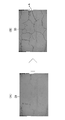
- FIG. 4 is a diagram illustrating a case where the damage information acquisition unit 30 acquires the damage information A.
- FIG. 4A shows a photographed image (first photographed image) 50 acquired by the damage information acquisition unit 30.
- the damage information acquisition unit 30 acquires the captured image 50 of the pier C captured at the time point a. Then, the damage information acquisition unit 30 extracts cracks from the captured image 50 by various techniques. For example, the damage information acquisition unit 30 extracts cracks from the captured image 50 by a detector subjected to image processing or machine learning, and acquires damage information A (vector information).
- FIG. 4B shows the damage information A acquired by the damage information acquisition unit 30.
- the damage information A is vector information, but a damage diagram generated based on the vector information is shown.
- the damage information acquisition unit 30 extracts the cracks shown in the captured image 50, generates them as damage information A, and acquires them.
- the damage information A is vector information, and has information on the position of the crack in the captured image 50 and information on the width and length of the crack.
- FIG. 5 is a diagram illustrating a case where the damage information acquisition unit 30 acquires the damage information B.
- FIG. 5A shows a photographed image (second photographed image) 54 acquired by the damage information acquisition unit 30.
- the damage information acquisition unit 30 acquires the captured image 54 of the pier C captured at the time point b. Then, the damage information acquisition unit 30 extracts cracks from the captured image 54 by various techniques. For example, the damage information acquisition unit 30 extracts cracks from the captured image 54 by a detector subjected to image processing or machine learning, and acquires damage information B (vector information).
- FIG. 5B shows the damage information B acquired by the damage information acquisition unit 30.
- the damage information B is vector information, but a damage diagram generated based on the vector information is shown.
- the damage information acquisition unit 30 extracts the cracks shown in the captured image 54, generates them as damage information B, and acquires them.
- the damage information B is vector information, and has information on the position of the crack in the captured image 54 and information on the width and length of the crack.
- the display output unit 36 displays a display recommending re-imaging on the display unit 26. It may be output and a display recommending re-shooting may be displayed on the display unit 26. The user can see this display and re-enter the captured image that has been re-photographed.
- the damage information acquisition unit 30 acquires the damage information A and the damage information B.
- the difference information extraction step is performed by the difference extraction unit 32.
- the difference extraction unit 32 extracts the difference between the damage information A and the damage information B by various methods. An example of the difference information extraction method of the difference extraction unit 32 will be described below.
- Example 1 the difference extraction unit 32 aligns the damage information A and the damage information B using the image feature, and extracts the difference information between the damage information A and the damage information B.
- the damage information acquisition unit 30 acquires the captured image 50 to acquire the damage information A and the captured image 54 to acquire the damage information B.
- the difference extraction unit 32 aligns the captured image 50 and the captured image 54, and aligns the damage information A and the damage information B based on the aligned information. conduct.
- FIG. 6 is a diagram illustrating the alignment of the captured image 50 and the captured image 54 by using the feature points of the captured image 50 and the captured image 54.
- the difference extraction unit 32 extracts the feature points of the captured image 50 and the captured image 54.
- the difference extraction unit 32 extracts the feature points in the captured image 50 and the captured image 54 by using the feature point detection technique of ORB (Oriented FAST and Rotated BRIEF) or AKAZE (ACCELERATED-KAZE).
- ORB Oriented FAST and Rotated BRIEF
- AKAZE ACCELERATED-KAZE
- FIG. 6 the feature point PA of one of the plurality of feature points extracted in the captured image 50 is shown.
- the feature point PB of one of the plurality of feature points extracted in the captured image 54 is shown.
- the difference extraction unit 32 derives the corresponding feature points between the captured image 50 and the captured image 54.
- the difference extraction unit 32 derives a corresponding point between the captured image 50 and the captured image 54 by using, for example, the techniques of Brief-Force and FLAN (Fast Library for Approximate Nearest Neighbors).
- FLAN Fast-Force and FLAN
- the difference extraction unit 32 derives the correspondence between the plurality of feature points of the captured image 50 and the plurality of feature points of the captured image 54 (detection of the corresponding points). After that, the difference extraction unit 32 aligns the captured image 50 and the captured image 54 using the detected corresponding points. Specifically, a coordinate conversion model (coordinate transformation matrix) between the coordinates on the captured image 50 and the coordinates on the captured image 54 is generated from the correspondence between the captured image 50 and the captured image 54. After that, the difference extraction unit 32 aligns the damage information A and the damage information B using the coordinate conversion model, and extracts the difference between the aligned damage information A and the damage information B.
- a coordinate conversion model coordinate transformation matrix
- Example 2 the difference extraction unit 32 aligns the damage information A and the damage information B by a method using matching by a dynamic programming method (DP (Dynamic Programming) matching), and causes the damage information A and the damage information B to be aligned with each other. Extract the difference information.
- DP Dynamic Programming
- the alignment method by DP matching is suitably used for extracting the difference in damage information regarding cracks.
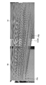
- FIG. 7 is a diagram illustrating the extraction of differences in damage information using DP matching.
- Damage information AP and damage information BP are damage information at different times of the same crack.
- the damage information AP and the damage information BP are vector information indicating cracks, respectively.
- the difference extraction unit 32 uses DP matching to derive the corresponding points a to d between the damage information AP and the damage information BP. Then, the difference extraction unit 32 extracts the difference information between the damage information AP and the damage information BP at each of the corresponding points a to d.
- Example 3 the difference extraction unit 32 aligns the damage information A and the damage information B by a method using AI (Artificial Intelligence), and extracts the difference information between the damage information A and the damage information B.
- AI Artificial Intelligence
- the difference extraction unit 32 aligns the captured image 50 and the captured image 54 using a recognizer that aligns the images, which is learned (generated) by using deep learning, and after the alignment, the captured image 50 and the captured image 54 are aligned. Based on the position information, the damage information A and the damage information B are aligned and the difference information is extracted.
- the difference extraction unit 32 aligns the damage information A and the damage information B by various methods, and after the alignment, extracts the difference between the damage information A and the damage information B. do.
- the detection step is performed by the detection unit 34.
- the detection unit 34 detects a first classification portion of the difference information, which has only the damage information A or the location where the damage information A is larger than the damage information B. Further, the detection unit 34 detects a second classification portion of the difference information, which has only the damage information B or the damage information B is larger than the damage information A. Further, the detection unit 34 has a third classification based on the difference information, the damage information A, and the damage information B, which is a place having the damage information A and the damage information B or a place where the damage information A and the damage information B are equal. Detect the location.
- the detection unit 34 detects a portion where the damage information A is larger than the damage information B in the quantitative value of the damage information as the first classification location. Further, the detection unit 34 detects a portion where the damage information B is larger than the damage information A in the quantitative value of the damage information as the second classification location. Further, the detection unit 34 detects a portion where the damage information A and the damage information B are equal in the quantitative value of the damage information as the third classification location.
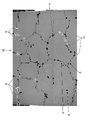
- FIG. 8 is a diagram showing an example of difference information between damage information A and damage information B.
- the difference information 52 is obtained by aligning the damage information A and the damage information B and subtracting the damage information A from the damage information B.
- the illustrated difference information 52 is displayed as a vector information obtained by subtracting the damage information A from the damage information B, the damage information A, and a damage diagram generated based on the damage information B.
- the location Q (the location surrounded by the dotted line) is the location where only the damage information A exists, or when the damage information is represented by a quantitative value, the damage information A is larger than the damage information B. It is a location, and the detection unit 34 detects it as a first classification location.
- the damage information B is more than the damage information A when only the damage information B exists or the damage information is represented by a quantitative value. It is a large location, and the detection unit 34 detects it as a second classification location. Further, in the difference information 52, the location S (dotted line location) is the location where the damage information A and the damage information B exist, or when the damage information is represented by a quantitative value, the damage information A and the damage information B are used. Is the same location, and the detection unit 34 detects as a third classification location.
- the detection unit 34 detects the first classification point and the second classification point in the difference information 52. Further, the detection unit 34 detects the third classification point based on the damage information A, the damage information B, and the difference information 52.
- FIG. 9 is a diagram showing an example of difference information (quantitative value) between damage information A and damage information B.
- the enlarged view 66 and the enlarged view 68 are enlarged views of a part of the difference information 52.
- the difference information is ⁇ 0.15, and the detection unit 34 detects the crack (number D96_3) portion as the first classification location.
- the difference information is 0.05, and the detection unit 34 detects the crack (number D97_3) portion as the second classification location.
- the difference information is 0.00, and the detection unit 34 detects the crack (number D14_1) portion as the third classification point.
- the detection unit 34 detects the first classification point and the second classification point in the difference information regarding the width of the crack. Further, the detection unit 34 detects the third classification point from the damage information A, the damage information B, and the difference information 52.
- the detection unit 34 has the first classification point, the second classification place, and the third classification place according to the place where the damage information A and the damage information B exist in the difference information 52. Is detected. Further, when the difference information 52 has a quantitative value, the detection unit 34 has a first classification point and a second classification according to the magnitude relationship (including the case where they are equal) between the damage information A and the damage information B. The location and the third classification location are detected.
- the display step is performed by the display output unit 36.
- the display output unit 36 outputs a notification display indicating the first classification location to the display unit 26, and performs a display process for displaying the notification display on the display unit 26. Further, the display output unit 36 outputs to the display unit 26 indicating the second classification location, and performs a display process for displaying the notification display on the display unit 26. In addition, the display output unit 36 performs display processing for displaying the notification display on the display unit 26 indicating the third classification location.
- FIG. 10 is a diagram showing an example in which a display image (damage diagram and notification display) output by the display output unit 36 is displayed on the display unit 26.
- the damage diagram 53 generated based on the damage information A and the damage information B is displayed on the display unit 26.
- a white solid line notification display M is displayed at the first classification location.
- a black solid line notification display N is displayed at the second classification location.
- a dotted line notification display P is performed at the third classification point. In this way, in the damage diagram 53 displayed on the display unit 26, the notification display is performed to the first classification point, the second classification place, and the third classification place according to the color and the line type.
- the display unit 26 displays a white balloon-shaped notification display V1 at the first classification location.
- the notification display V1 is displayed at a position where the first classification location is notified based on the damage information A detected as the first classification location.
- the display unit 26 displays a black balloon-shaped notification display V2 at the first classification point where the damage information A has a quantitative value larger than that of the damage information B. In this way, the display unit 26 displays the notification to the first classification location by a marker such as a balloon in the damage diagram 53.
- the difference information 52 between the damage information A and the damage information B is extracted, and the first classification portion of the difference information 52 is detected. Then, in this embodiment, the display unit 26 is displayed with a notification display indicating the first classification point in association with the damage information of at least one of the damage information A and the damage information B, so that the user can use unnatural difference information in time series. Can be recognized.
- the second classification point is detected in the difference information 52. Then, in this embodiment, the display unit 26 is displayed with a notification display indicating the second classification location in association with the damage information of at least one of the damage information A and the damage information B, so that the user recognizes the location where the damage has grown or developed. Can be made to.
- the third classification point is detected based on the difference information 52, the damage information A, and the damage information B. Then, in this embodiment, the display unit 26 is displayed with a notification display indicating the third classification location in association with the damage information of at least one of the damage information A and the damage information B, so that the user can see the location where the damage has not changed. Can be recognized.
- FIG. 11 is a diagram illustrating an example of the display form of this example.
- FIG. 11A is a diagram showing damage FIG. 53 displayed on the display unit 26.
- the user designates a part of the area F in the damage diagram 53 displayed on the display unit 26.
- the display output unit 36 accepts the designation of a part of the area, and outputs the photographed image 62 and the photographed image 64 corresponding to the designated area to the display unit 26.
- FIG. 11B is a diagram showing a captured image 62 and a captured image 64 displayed on the display unit 26.
- the captured image 62 is an enlarged view of an area corresponding to the F region of the captured image 50.
- the captured image 64 is an enlarged view of an area corresponding to the F region of the captured image 54.
- the captured image 62 and the captured image 64 are output from the display output unit 36 to the display unit 26. Then, the display output unit 36 performs a display process of displaying (comparative display) the photographed image 62 and the photographed image 64 side by side so that they can be compared with each other on the display unit 26.
- the corresponding damage diagram may be superimposed and displayed on the captured image 62 and the captured image 64.
- the user compares the state of the past inspection target with the state of the current inspection target. Can be observed.
- the damage information (damage information A or damage information B) corresponding to the first classification point can be corrected by various methods. Therefore, the display output unit 36 outputs a single or a plurality of correction methods to the display unit 26. Then, the display unit 26 displays the input correction method and presents the correction method to the user. A specific example of the correction method will be described below.
- the damage information corresponding to the first classification point can be corrected by using the inspection date and time and the temperature at the time of inspection. For example, since the volume of concrete changes due to temperature changes, the temperature is estimated from the inspection date and time and image features, and the quantitative value (crack width) in the damage information is corrected. Further, the user can correct the quantitative value in the damage information by inputting the date and time and the temperature.
- the damage information of the first classification location is generated by the detector subjected to machine learning
- the damage information can be corrected by changing the threshold value or the like.
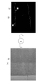
- FIG. 12 is a diagram illustrating crack detection from a captured image by a detector.
- FIG. 12A shows a photographed image 70 of the inspection target.
- the detector (AI) trained by machine learning
- the cracks reflected in the captured image 70 are detected and the detection result 72 is output.
- the detector (AI) outputs the probability of cracking, and detects those having a probability of a predetermined threshold value or more as damage.
- FIG. 12B is a diagram showing the detection result 72 output from the detector (AI).
- the detector (AI) generates a detection result 72 by regarding a crack having a crack probability of 30% or more as a crack.
- the portion having a high probability of cracking is represented by a dark line (indicated by arrow I), and the portion having a low probability of cracking is represented by a light line (arrow H).
- the probability of cracking is displayed as a pixel value.
- the threshold value of the damage detection when the damage information B is generated is lowered.
- the detector (AI) rediscover the damage.
- the damage corresponding to the damage information A is also detected in the damage information B, and the damage information A and the damage information B are present in the detected place as the first classification place, or the quantitative value of the damage information B is obtained. Is corrected, and the correction of the first classification point is performed. Further, as another method, when the first classification point where only the damage information A exists or the damage information A is larger than the damage information B is corrected, the damage when the damage information A is generated is corrected.
- the display output unit 36 outputs the single or multiple correction methods of the damage information (damage information A or damage information B) corresponding to the first classification location to the display unit 26, and the display unit 26 Shows the correction method to the user by displaying the correction method on the display unit 26.
- ⁇ Third modification example> a third modification of the above-described embodiment will be described.
- the user manually corrects the damage information A or the damage information B, and the difference extraction process is performed again.
- the damage information (damage information A or damage information B) corresponding to the first classification location is corrected. In this example, this correction is done manually by the user.
- FIG. 13 is a diagram illustrating an example of acceptance of correction of damage information.
- the crack damage diagram 80 When the crack damage diagram 80 is displayed on the display unit 26 based on the damage information, the user adds the crack damage diagram 82 by the pointing device. Damage The addition of FIG. 82 is accepted by the damage information acquisition unit 30 as correction information. Then, the damage information acquisition unit 30 corrects the existing damage information based on the correction information, and then the difference extraction unit 32 extracts the difference information again.
- FIG. 14 is a diagram illustrating another example of accepting correction of damage information.
- the damage diagram 84 of the damaged region (for example, peeling) is shown on the display unit 26 based on the damage information
- the user adds the damage diagram 86 of the damaged region by the pointing device. Damage
- the addition of FIG. 86 is accepted by the damage information acquisition unit 30 as correction information.
- the damage information acquisition unit 30 corrects the existing damage information based on the correction information, and then the difference extraction unit 32 extracts the difference information again.
- the user can correct the damage information by adding or deleting trace lines. Further, in the case of surface damage such as peeling, the user can correct the damage information by adding or deleting an area.
- the damage information acquisition unit 30 deletes the damage information A of the portion detected as the first classification location, or adds damage as damage information B to the location detected as the first classification location to cause damage. Information can also be corrected automatically.
- FIG. 15 is a diagram showing a damage diagram of this example displayed on the display unit 26.
- the display unit 26 is controlled by the display output unit 36 so as to display the display image output from the display output unit 36.
- the damage diagram 55 is a damage diagram generated based on the damage information corresponding to the second classification location.
- the line type of the damage diagram showing the crack is changed according to the magnitude of the difference in the difference information (crack width) of the quantitative value.
- the damage diagram indicated by the arrow W corresponds to the difference information in which the amount of growth of the crack width is large.
- the display form of this damage diagram is represented by a thin dotted line.
- the damage diagram indicated by the arrow X corresponds to the difference information in which the amount of growth of the crack width is medium.
- the display form of this damage diagram is indicated by a thick dotted line.
- the damage diagram indicated by the arrow Y corresponds to the difference information in which the amount of growth of the crack width is small. This damage information is shown as a solid line.
- FIG. 16 is a diagram for explaining the display and non-display of the damage diagram corresponding to the first classification portion on the display unit 26.
- the display unit 26 is controlled by the display output unit 36 so as to display the display image output from the display output unit 36.
- FIG. 16A is a diagram showing the damage FIG. 53 displayed on the display unit 26.
- the damage diagram 53 displays all the damage diagrams generated from the damage information corresponding to the first classification point, the second classification point, and the third classification point.
- the damage diagram corresponding to the first classification point is indicated by a white line (indicated by an arrow Z).
- FIG. 16B is a diagram showing the damage diagram 53 in which the damage diagram (arrow Z) corresponding to the first classification location is hidden.
- the display output unit 36 outputs a display image in which the first classification portion is hidden to the display unit 26, and performs a display process for causing the display unit 26 to display the image.
- the damage diagram desired by the user can be displayed.
- a display can be provided.
- the hardware-like structure of the processing unit that executes various processes is various processors as shown below.
- the circuit configuration can be changed after manufacturing the CPU (Central Processing Unit), FPGA (Field Programmable Gate Array), etc., which are general-purpose processors that execute software (programs) and function as various processing units.
- Programmable Logic Device which is a processor, and a dedicated electric circuit, which is a processor having a circuit configuration specially designed to execute a specific process such as ASIC (Application Specific Integrated Circuit). Is done.
- One processing unit may be composed of one of these various processors, or may be composed of two or more processors of the same type or different types (for example, a plurality of FPGAs or a combination of a CPU and an FPGA). You may. Further, a plurality of processing units may be configured by one processor. As an example of configuring a plurality of processing units with one processor, first, one processor is configured by a combination of one or more CPUs and software, as represented by a computer such as a client or a server. There is a form in which the processor functions as a plurality of processing units.
- SoC System On Chip
- the various processing units are configured by using one or more of the above-mentioned various processors as a hardware-like structure.
- the hardware-like structure of these various processors is, more specifically, an electric circuit (circuitry) in which circuit elements such as semiconductor elements are combined.
- Damage information processing device 12 Data acquisition unit 16: Memory 18: Operation unit 20: CPU 22: RAM 24: ROM 26: Display unit 30: Damage information acquisition unit 32: Difference extraction unit 34: Detection unit 36: Display output unit
Landscapes
- Engineering & Computer Science (AREA)
- Theoretical Computer Science (AREA)
- Physics & Mathematics (AREA)
- General Physics & Mathematics (AREA)
- Computer Vision & Pattern Recognition (AREA)
- Business, Economics & Management (AREA)
- Quality & Reliability (AREA)
- General Health & Medical Sciences (AREA)
- Health & Medical Sciences (AREA)
- Human Resources & Organizations (AREA)
- Evolutionary Computation (AREA)
- Databases & Information Systems (AREA)
- Medical Informatics (AREA)
- Computing Systems (AREA)
- Software Systems (AREA)
- Artificial Intelligence (AREA)
- Multimedia (AREA)
- Strategic Management (AREA)
- Marketing (AREA)
- Economics (AREA)
- Entrepreneurship & Innovation (AREA)
- Operations Research (AREA)
- Tourism & Hospitality (AREA)
- General Business, Economics & Management (AREA)
- Life Sciences & Earth Sciences (AREA)
- Chemical & Material Sciences (AREA)
- Pathology (AREA)
- Biochemistry (AREA)
- Immunology (AREA)
- Analytical Chemistry (AREA)
- Investigating Materials By The Use Of Optical Means Adapted For Particular Applications (AREA)
- Management, Administration, Business Operations System, And Electronic Commerce (AREA)
- Image Analysis (AREA)
Abstract
時系列的に不自然な差分を有する箇所をユーザが容易に認識することができる損傷情報処理装置、損傷情報処理方法、及びプログラムを提供する。損傷情報処理装置(10)は、プロセッサ(20)を備える、構造物の損傷情報処理装置(10)である。プロセッサ(20)は、構造物の損傷情報であって、第1の損傷情報及び第1の損傷情報よりも時系列的に後の時点の第2の損傷情報を取得し、第1の損傷情報と第2の損傷情報との差分である差分情報を抽出し、差分情報のうち、第1の損傷情報のみ存在する又は第1の損傷情報が第2の損傷情報よりも大きい第1の分類箇所を検出し、第1の損傷情報及び第2の損傷情報の少なくとも一方の損傷情報と関連付けて、第1の分類箇所を示す報知表示を表示装置に出力する。
Description
本発明は、損傷情報処理装置、損傷情報処理方法、及びプログラムに関し、特に、構造物の損傷情報を処理する損傷情報処理装置、損傷情報処理方法、及びプログラムである。
構造物は、老朽化等により損傷が発生することがある。したがって、構造物の損傷に関する点検は、定期的に行われることが多い。そして定期的な点検を行う場合には、過去の点検結果と現在の点検結果を比較して、損傷の成長度合いを把握することが望まれており、これを支援する技術が検討されてきた。
特許文献1では、異なる時刻に同じひび割れを撮影した2枚の画像を取得し、その2枚の画像からひび割れの長さ方向の変化及び幅方向の変化を判定する技術が記載されている。
ここで、損傷の成長度合いを確認するため、異なる時点の二つの点検結果の差分を抽出することがある。この差分を抽出する場合に、様々な理由により、時系列的に不自然な差分となってしまう場合がある。ここで、時系列的に不自然な差分とは例えば、損傷の補修を行っていないにもかかわらず、過去の点検結果では損傷が存在した箇所において、現在の点検結果では同じ位置にその損傷の存在が確認できない場合である。また、時系列的に不自然な差分とは例えば、損傷の補修を行っていないにもかかわらず、損傷の定量値(長さ、幅、又は面積)が現在の点検結果の方が過去の点検結果に比べて小さい場合である。すなわち、時系列的に不自然な差分とは、時系列的に不可逆変化に反する結果が得られる場合である。
このように、時系列的に不自然な差分が出力されてしまう原因として、過去の点検結果と現在の点検結果とで、点検条件(点検作業員・使用機器・環境)が異なる場合、点検対象の撮影画像の撮影不備、撮影画像からの損傷の抽出不備などが考えられる。
したがって、点検者(ユーザ)は、このような時系列的に不自然な差分となった箇所を認識し、不自然な差分となった箇所に対して、点検条件の見直しや、再撮影、再度の損傷の抽出など対策を行うことが必要である。上述した特許文献1では、このように時系列的に不自然な差分については言及されていない。
本発明はこのような事情に鑑みてなされたもので、その目的は、時系列的に不自然な差分を有する箇所をユーザが容易に認識することができる損傷情報処理装置、損傷情報処理方法、及びプログラムを提供することである。
上記目的を達成するために、本発明の一の態様である損傷情報処理装置は、プロセッサを備える、構造物の損傷情報処理装置であって、プロセッサは、構造物の損傷情報であって、第1の損傷情報及び第1の損傷情報よりも時系列的に後の時点の第2の損傷情報を取得し、第1の損傷情報と第2の損傷情報との差分である差分情報を抽出し、差分情報のうち、第1の損傷情報のみ存在する又は第1の損傷情報が第2の損傷情報よりも大きい第1の分類箇所を検出し、第1の損傷情報及び第2の損傷情報の少なくとも一方の損傷情報と関連付けて、第1の分類箇所を示す報知表示を表示装置に出力する。
本態様によれば、第1の損傷情報と第2の損傷情報との差分情報が抽出され、その差分情報のうち、第1の損傷情報にのみ存在する第1の分類箇所を検出する。また、差分情報のうち、第1の損傷情報が第2の損傷情報よりも大きい第1の分類箇所を検出する。ここで、第1の分類箇所とは、時系列的に先の第1の損傷情報のみが存在する箇所又は第1の損傷情報が第2の損傷情報よりも大きい箇所であり、時系列的に不自然な差分情報を有する箇所である。そして本態様は、第1の損傷情報及び第2の損傷情報の少なくとも一方の損傷情報と関連付けて第1の分類箇所を示す報知表示を表示装置に出力することで、表示装置は報知表示を表示し、ユーザは容易に第1の分類箇所を認識することができる。
好ましくは、プロセッサは、差分情報のうち、第2の損傷情報のみ存在する又は第2の損傷情報が第1の損傷情報よりも大きい第2の分類箇所を検出し、第1の損傷情報及び第2の損傷情報の少なくとも一方の損傷情報と関連付けて、第2の分類箇所を示す報知表示を表示装置に出力する。
好ましくは、プロセッサは、差分情報、第1の損傷情報、及び第2の損傷情報に基づいて、第1の損傷情報と第2の損傷情報とが重なる又は第1の損傷情報と第2の損傷情報とが等しい第3の分類箇所を検出し、第1の損傷情報及び第2の損傷情報の少なくとも一方の損傷情報と関連付けて、第3の分類箇所を示す報知表示を表示装置に出力する。
好ましくは、プロセッサは、第1の分類箇所に対応する損傷情報、第2の分類箇所に対応する損傷情報、又は第3の分類箇所に対応する損傷情報に関連した表示の表示装置への表示及び非表示を切り替えて行う。
好ましくは、プロセッサは、差分情報に含まれる差分の大きさに応じて、第2の分類箇所の表示形態を変える。
好ましくは、プロセッサは、第1の損傷情報と第2の損傷情報とを重畳した情報に関連する表示を、表示装置に表示させる表示処理を行う。
好ましくは、プロセッサは、第1の損傷情報を取得した第1の撮影画像及び第2の損傷情報を取得した第2の撮影画像を取得し、第1の撮影画像と第2の撮影画像とを並べて表示装置に表示させる表示処理を行う。
好ましくは、プロセッサは、第1の撮影画像又は第2の撮影画像が予め決められた条件を満たさない場合には、再撮影を推奨する表示を表示装置に表示させる表示処理を行う。
好ましくは、プロセッサは、第1の分類箇所に対応する第1の損傷情報又は第2の損傷情報の単数又は複数の補正方法を表示装置に出力する。
好ましくは、プロセッサは、表示装置に表示されている第1の損傷情報又は第2の損傷情報の補正情報を受け付け、補正された第1の損傷情報又は第2の損傷情報に基づいて、再度差分情報を抽出する。
好ましくは、プロセッサは、第1の分類箇所に対応する第1の損傷情報又は第2の損傷情報を自動で補正する。
本発明の他の態様である損傷情報処理方法は、プロセッサを備える、構造物の損傷情報処理装置の損傷情報処理方法であって、プロセッサが行う、構造物の損傷情報であって、第1の損傷情報及び第1の損傷情報よりも時系列的に後の時点の第2の損傷情報を取得するステップと、第1の損傷情報と第2の損傷情報との差分である差分情報を抽出するステップと、差分情報のうち、第1の損傷情報のみ存在する又は第1の損傷情報が第2の損傷情報よりも大きい第1の分類箇所を検出するステップと、第1の損傷情報及び第2の損傷情報の少なくとも一方の損傷情報と関連付けて、第1の分類箇所を示す報知表示を表示装置に出力するステップと、を含む。
本発明の他の態様であるプログラムは、プロセッサを備える、構造物の損傷情報処理装置に損傷情報処理方法を実行させるプログラムであって、プロセッサに、構造物の損傷情報であって、第1の損傷情報及び第1の損傷情報よりも時系列的に後の時点の第2の損傷情報を取得するステップと、第1の損傷情報と第2の損傷情報との差分である差分情報を抽出するステップと、差分情報のうち、第1の損傷情報のみ存在する又は第1の損傷情報が第2の損傷情報よりも大きい第1の分類箇所を検出するステップと、第1の損傷情報及び第2の損傷情報の少なくとも一方の損傷情報と関連付けて、第1の分類箇所を示す報知表示を表示装置に出力するステップと、を実行させる。
本発明によれば、第1の損傷情報と第2の損傷情報との差分情報が抽出され、その差分情報のうち、第1の損傷情報にのみ存在する、又は、第1の損傷情報が第2の損傷情報よりも大きい第1の分類箇所を検出し、第1の損傷情報及び第2の損傷情報の少なくとも一方の損傷情報と関連付けて第1の分類箇所を示す報知表示を表示装置に出力することで、表示装置は報知表示を表示し、ユーザは容易に第1の分類箇所を認識することができる。
以下、添付図面にしたがって本発明にかかる損傷情報処理装置、損傷情報処理方法、及びプログラムの好ましい実施の形態について説明する。
図1は、損傷情報処理装置10のハードウェア構成の一例を示すブロック図である。
損傷情報処理装置10は、コンピュータ又はワークステーションで構成することができる。損傷情報処理装置10のハードウェア構成は、主としてデータ取得部12と、メモリ16と、操作部18と、CPU(プロセッサ)(Central Processing Unit)20と、RAM(Random Access Memory)22と、ROM(Read Only Memory)24とから構成される。また、損傷情報処理装置10は、表示部(表示装置)26に表示用画像を出力する。表示部26は、ネットワークで接続されたクライアントサーバシステムのクライアント端末の表示部26であり、損傷情報処理装置10はクラインアト端末からの要求に応答するサーバとして機能する。したがって、損傷情報処理装置10から出力された表示用画像は、表示部26に表示される。また、別の形態としては、損傷情報処理装置10はコンピュータに搭載され、表示部26はコンピュータに接続されるモニタで構成される。
データ取得部12は、データの入力部であり、例えばメモリ16に記憶される情報(データ)を取得する。なお、メモリ16に記憶される情報は、データ取得部12で取得されてもよいし、予めメモリ16に記憶されていてもよい。例えば、データ取得部12では、後で説明する点検対象の撮影画像や損傷情報を取得する。
メモリ16は、データベースとして機能する。メモリ16は、データ取得部12で取得された点検対象の撮影画像や損傷情報を記憶する。例えばメモリ16は、定期的に行われた構造物の点検結果である撮影画像や損傷画像を過去から蓄積して記憶している。なお、点検対象の構造物は、建造物、例えば、橋梁、トンネル、ダムなどの土木構造物を含み、その他にビル、家屋、建物の壁、柱、梁などの建築物をも包含するものである。また、点検で検出される構造物の損傷は、ひび割れ、剥離、鉄筋露出、漏水、遊離石灰、腐食などである。
操作部18は、キーボードやマウス等のポインティングデバイスで構成される。ユーザは操作部18を介して指令を損傷情報処理装置10に入力する。
CPU20は、メモリ16又はROM24に記憶されるプログラムをRAM22に展開して実行することにより、各機能を実現する。
図2は、CPU20が備える機能のブロック図である。
CPU20は、損傷情報取得部30、差分抽出部32、検出部34、及び表示出力部36を備える。
損傷情報取得部30は損傷情報を取得する。ここで、損傷情報とは、点検対象の構造物の損傷に関する情報を表している情報であり、様々な態様の情報である。例えば、損傷情報は、損傷(ひび割れ)を示すベクトル情報である。また、損傷情報は、損傷(剥離、鉄筋露出、漏水、遊離石灰、腐食)の領域情報である。
損傷情報取得部30は、同一の損傷について異なる時点で取得された二つの損傷情報を取得する。損傷情報取得部30は、例えばメモリ16に記憶されている定期点検で得られた損傷情報を取得する。損傷情報取得部30は、a時点で取得された損傷情報A(第1の損傷情報)、損傷情報Aと同一の損傷に関する損傷情報でありb時点で取得された損傷情報B(第2の損傷情報)を取得する。なお、a時点はb時点よりも過去の時点であり、例えばa時点は2015年8月でありb時点は2020年8月である。なお、a時点、b時点は、異なる時点であればよく特に限定されるものではない。
差分抽出部32は、損傷情報Aと損傷情報Bとの差分である差分情報を抽出する。差分抽出部32は、損傷情報Aと損傷情報Bとの相互に異なる箇所を差分情報として抽出する。例えば、損傷情報A及び損傷情報Bが同じひび割れをベクトル情報で表している場合には、損傷情報Aと損傷情報Bとの異なる箇所が差分情報として抽出される。また、例えば損傷情報A及び損傷情報Bが、同じ剥離の領域を面積で表している場合には、損傷情報Aと損傷情報Bとの異なる箇所が抽出される。また、差分抽出部32は、損傷情報Aと損傷情報Bとの定量値(長さ、幅、面積)の差分情報を抽出してもよい。例えば、損傷情報Aと損傷情報Bとがひび割れ幅に関する情報を有している場合には、そのひび割れ幅の差分情報を抽出する。
検出部34は、差分情報のうち、時系列的に不自然な差分を有する箇所である第1の分類箇所を検出する。ここで、第1の分類箇所とは、差分情報のうち損傷情報Aのみ存在する箇所である。また、第1の分類箇所とは、損傷情報が定量値で表されている場合には、損傷情報Aが損傷情報Bよりも大きい箇所である。損傷情報Aは損傷情報Bよりも時系列的に前の時点で取得されたにもかかわらず、損傷情報Aには存在するが損傷情報Bには存在しない箇所は時系列的に不自然である。また、損傷情報Aは損傷情報Bよりも時系列的に前の時点で取得されたにもかかわらず、損傷情報Aの定量値の方が損傷情報Bの定量値よりも大きい箇所は、時系列的に不自然である。なお、損傷情報A、損傷情報Bは、検出された損傷に対して補修(修理)が実施されていないこととする。
また、検出部34は、差分情報のうち、損傷が成長又は発現した箇所である第2の分類箇所を検出する。ここで第2の分類箇所とは、差分情報のうち損傷情報Bのみ存在する箇所である。また、第2の分類箇所とは、損傷情報が定量値で表されている場合には、損傷情報Bが損傷情報Aよりも大きい箇所である。損傷情報Aを取得した時点aから損傷が成長又は発現すると、損傷情報Bのみにその損傷に対応する損傷情報が反映される。
また、検出部34は、損傷情報A、損傷情報B、及び差分情報に基づいて、損傷情報Aと損傷情報Bとが重なる第3の分類箇所を検出する。また、検出部34は、損傷情報A、損傷情報B、及び差分情報に基づいて、損傷情報が定量値で表されている場合には、損傷情報Aと損傷情報Bとが等しい第3の分類箇所を検出する。第3の分類箇所は、損傷情報Aを取得した時点と損傷情報Bを取得した時点とで変化が見られない損傷の箇所である。
なお、検出部34は、必要に応じて(ユーザの設定など)上述した第2の分類箇所及び第3の分類箇所を検出する。したがって、検出部34は、第1の分類箇所のみ検出する態様、第1の分類箇所及び第2の分類箇所を検出する態様、第1の分類箇所及び第3の分類箇所を検出する態様、又は、第1の分類箇所、第2の分類箇所及び第3の分類箇所を検出する態様を採用することができる。
表示出力部36は、表示部26に表示を行う表示用画像を出力する。表示出力部36は、損傷情報Aと損傷情報Bとを出力して、損傷情報Aと損傷情報Bとを表示部26に表示させる表示処理を行う。例えば表示出力部36は、損傷情報Aと損傷情報Bとを重ねて(重畳して)表示部26に表示する。また、表示出力部36は、表示された損傷情報A及び損傷情報Bの少なくとも一方の損傷情報と関連付けて、第1の分類箇所を示す報知表示を表示部26に出力して、表示部26に報知表示を表示する。このように、第1の分類箇所を示す報知表示を表示部26に出力し、表示部26に報知表示が表示されることにより、第1の分類箇所をユーザに報知することができ、ユーザは容易に第1の分類箇所を認識することができる。
また、表示出力部36は、表示された損傷情報A及び損傷情報Bの少なくとも一方の損傷情報と関連付けて、第2の分類箇所を示す報知表示を表示部26に出力して、表示部26に報知表示を表示する。このように、第2の分類箇所を示す報知表示を表示部26に出力し、表示部26に報知表示が表示されることにより、第2の分類箇所をユーザに報知することができ、ユーザは成長又は出現した損傷に容易に認識することができる。
また、表示出力部36は、表示された損傷情報A及び損傷情報Bの少なくとも一方の損傷情報と関連付けて、第3の分類箇所を示す報知表示を表示部26に出力して、表示部26に報知表示を表示する。このように、第3の分類箇所を示す報知表示を表示部26に出力し、表示部26に報知表示が表示されることにより、第3の分類箇所をユーザに報知することでき、より正確な点検を行うことができる。
次に、損傷情報処理装置10を使用した損傷情報処理方法に関して説明する。図3は、損傷情報処理装置10を使用した表示方法を示すフロー図である。
先ず、損傷情報処理装置10は、損傷情報取得部30により、損傷情報A及び損傷情報Bを取得する(ステップS10:損傷情報取得ステップ)。次に、損傷情報処理装置10は、差分抽出部32により、損傷情報Aと損傷情報Bとの差分情報を抽出する(ステップS11:差分情報抽出ステップ)。その後、損傷情報処理装置10は、検出部34により、差分情報のうち第1の分類箇所を検出する(ステップS12:検出ステップ)。なお、検出部34は、ユーザの設定により、差分情報のうち、第2の分類箇所及び/又は第3の分類箇所を検出する。次に、損傷情報処理装置10は、表示出力部36により、第1の分類箇所を示す報知表示を表示部26に出力する(ステップS13:表示ステップ)。また、表示出力部36は、第2の分類箇所及び/又は第3の分類箇所を示す報知表示を表示部26に出力する。
次に、上述した表示方法の各ステップの詳しい説明を行う。
<損傷情報取得ステップ>
損傷情報取得ステップは損傷情報取得部30により行われる。損傷情報取得部30は、損傷情報を取得してもよいし、入力画像から損傷を抽出して損傷情報を生成し取得してもよい。以下に、損傷情報取得部30に撮影画像が入力され、損傷情報取得部30はその撮影画像から損傷を抽出して損傷情報を取得する場合について説明する。
損傷情報取得ステップは損傷情報取得部30により行われる。損傷情報取得部30は、損傷情報を取得してもよいし、入力画像から損傷を抽出して損傷情報を生成し取得してもよい。以下に、損傷情報取得部30に撮影画像が入力され、損傷情報取得部30はその撮影画像から損傷を抽出して損傷情報を取得する場合について説明する。
図4は、損傷情報取得部30が損傷情報Aを取得する場合について説明する図である。
図4(A)には、損傷情報取得部30が取得した撮影画像(第1の撮影画像)50が示されている。損傷情報取得部30は、時点aで撮影された橋脚Cの撮影画像50を取得する。そして、損傷情報取得部30は、撮影画像50から様々な技術によりひび割れを抽出する。例えば損傷情報取得部30は、画像処理又は機械学習が行われた検出器により、撮影画像50からひび割れを抽出し、損傷情報A(ベクトル情報)を取得する。
図4(B)には、損傷情報取得部30が取得した損傷情報Aが示されている。なお、損傷情報Aはベクトル情報であるが、ベクトル情報を基に生成された損傷図が図示されている。損傷情報取得部30は、撮影画像50に写っていたひび割れを抽出して損傷情報Aとして生成し取得する。損傷情報Aは、ベクトル情報であり、撮影画像50におけるひび割れの位置情報、ひび割れの幅及び長さの情報を有する。
図5は、損傷情報取得部30が損傷情報Bを取得する場合について説明する図である。
図5(A)には、損傷情報取得部30が取得した撮影画像(第2の撮影画像)54が示されている。損傷情報取得部30は、時点bで撮影された橋脚Cの撮影画像54を取得する。そして、損傷情報取得部30は、撮影画像54から様々な技術によりひび割れを抽出する。例えば損傷情報取得部30は、画像処理又は機械学習が行われた検出器により、撮影画像54からひび割れを抽出し、損傷情報B(ベクトル情報)を取得する。
図5(B)には、損傷情報取得部30が取得した損傷情報Bが示されている。なお、損傷情報Bはベクトル情報であるが、ベクトル情報を基に生成された損傷図が図示されている。損傷情報取得部30は、撮影画像54に写っていたひび割れを抽出して損傷情報Bとして生成し取得する。損傷情報Bは、ベクトル情報であり、撮影画像54におけるひび割れの位置情報、ひび割れの幅及び長さの情報を有する。
なお、入力された撮影画像50及び撮影画像54が損傷情報の取得に適さない場合(予め決められ条件を満たさない場合)には、表示出力部36は再撮影を推奨する表示を表示部26に出力し、表示部26に再撮影を推奨する表示を表示させてもよい。ユーザはこの表示をみて、再撮影を行った撮影画像を再度入力することができる。
以上で説明したように、損傷情報取得ステップでは損傷情報取得部30により、損傷情報A及び損傷情報Bが取得される。
<差分情報抽出ステップ>
差分情報抽出ステップは差分抽出部32で行われる。差分抽出部32は、様々な手法により損傷情報Aと損傷情報Bとの差分を抽出する。以下に差分抽出部32の差分情報の抽出手法の例を説明する。
差分情報抽出ステップは差分抽出部32で行われる。差分抽出部32は、様々な手法により損傷情報Aと損傷情報Bとの差分を抽出する。以下に差分抽出部32の差分情報の抽出手法の例を説明する。
(例1)
例1では差分抽出部32は、画像特徴を用いて、損傷情報A及び損傷情報Bの位置合わせを行い損傷情報Aと損傷情報Bとの差分情報を抽出する。上述した例では、損傷情報取得部30は、損傷情報Aを取得するために撮影画像50、及び損傷情報Bを取得するために撮影画像54を取得している。このような場合には、差分抽出部32は、撮影画像50と撮影画像54との位置合わせを行い、その位置合わせを行った情報に基づいて、損傷情報Aと損傷情報Bとの位置合わせを行う。
例1では差分抽出部32は、画像特徴を用いて、損傷情報A及び損傷情報Bの位置合わせを行い損傷情報Aと損傷情報Bとの差分情報を抽出する。上述した例では、損傷情報取得部30は、損傷情報Aを取得するために撮影画像50、及び損傷情報Bを取得するために撮影画像54を取得している。このような場合には、差分抽出部32は、撮影画像50と撮影画像54との位置合わせを行い、その位置合わせを行った情報に基づいて、損傷情報Aと損傷情報Bとの位置合わせを行う。
図6は、撮影画像50及び撮影画像54の特徴点を用いて、撮影画像50と撮影画像54との位置合わせを説明する図である。
先ず差分抽出部32は、撮影画像50及び撮影画像54の特徴点を抽出する。例えば、差分抽出部32は、ORB(Oriented FAST and Rotated BRIEF)、又はAKAZE(ACCELERATED-KAZE)の特徴点の検出技術を使用して、撮影画像50と撮影画像54での特徴点を抽出する。図6では、撮影画像50において抽出された複数の特徴点のうちの一つの特徴点PAが示されている。また、撮影画像54において抽出された複数の特徴点のうちの一つの特徴点PBが示されている。
その後、差分抽出部32は、撮影画像50と撮影画像54との間で対応する特徴点を導出する。差分抽出部32は、例えば、Brue-Force、FLANN(Fast Library for Approximate Nearest Neighbors)の技術を用いて、撮影画像50と撮影画像54との間の対応点を導出する。図6に示す場合では、直線CORにより、特徴点PAと特徴点PBとの対応関係が示されている。
上述したように差分抽出部32は、撮影画像50の複数の特徴点と撮影画像54の複数の特徴点の対応関係を導出する(対応点の検出)。その後、差分抽出部32は、検出した対応点を用いて、撮影画像50と撮影画像54との位置合わせを行う。具体的には、撮影画像50と撮影画像54との対応関係から、撮影画像50上の座標と撮影画像54上の座標との座標変換モデル(座標変換行列)を生成する。その後、差分抽出部32は、損傷情報Aと損傷情報Bとの位置合わせを、座標変換モデルを使用して行い、位置合わせが行われた損傷情報Aと損傷情報Bとで差分を抽出する。
(例2)
例2では差分抽出部32は、動的計画法によるマッチング(DP(Dynamic Programming)マッチング)を用いた方法により損傷情報A及び損傷情報Bの位置合わせを行い、損傷情報Aと損傷情報Bとの差分情報を抽出する。なお、DPマッチングによる位置合わせの手法は、ひび割れに関する損傷情報の差分の抽出に好適に用いられる。
例2では差分抽出部32は、動的計画法によるマッチング(DP(Dynamic Programming)マッチング)を用いた方法により損傷情報A及び損傷情報Bの位置合わせを行い、損傷情報Aと損傷情報Bとの差分情報を抽出する。なお、DPマッチングによる位置合わせの手法は、ひび割れに関する損傷情報の差分の抽出に好適に用いられる。
図7は、DPマッチングを使用した損傷情報の差分の抽出に関して説明する図である。
損傷情報AP及び損傷情報BPは、同一のひび割れの異なる時点での損傷情報である。損傷情報AP及び損傷情報BPはそれぞれ、ひび割れを示すベクトル情報である。差分抽出部32は、DPマッチングを使用して、損傷情報APと損傷情報BPとの対応箇所a~dを導出する。そして、差分抽出部32は、対応箇所a~dのそれぞれにおける損傷情報APと損傷情報BPとの差分情報を抽出する。
(例3)
例3では差分抽出部32は、AI(Artificial Intelligence)を用いた方法により、損傷情報A及び損傷情報Bの位置合わせを行い、損傷情報Aと損傷情報Bとの差分情報を抽出する。例えば差分抽出部32は、深層学習を用いて学習(生成)された、画像の位置合わせを行う認識器を使用して撮影画像50と撮影画像54との位置合わせを行い、その位置合わせ後の位置情報に基づいて、損傷情報Aと損傷情報Bとの位置合わせを行って、差分情報を抽出する。
例3では差分抽出部32は、AI(Artificial Intelligence)を用いた方法により、損傷情報A及び損傷情報Bの位置合わせを行い、損傷情報Aと損傷情報Bとの差分情報を抽出する。例えば差分抽出部32は、深層学習を用いて学習(生成)された、画像の位置合わせを行う認識器を使用して撮影画像50と撮影画像54との位置合わせを行い、その位置合わせ後の位置情報に基づいて、損傷情報Aと損傷情報Bとの位置合わせを行って、差分情報を抽出する。
以上で説明したように、差分抽出部32は、様々な手法により損傷情報Aと損傷情報Bとの位置合わせを行い、位置合わせを行った後に、損傷情報Aと損傷情報Bとの差分を抽出する。
<検出ステップ>
検出ステップは、検出部34により行われる。検出部34は、差分情報のうち、損傷情報Aのみを有する箇所又は損傷情報Aが損傷情報Bよりも大きい箇所である第1の分類箇所を検出する。また、検出部34は、差分情報のうち、損傷情報Bのみ有する箇所又は損傷情報Bが損傷情報Aよりも大きい箇所である第2の分類箇所を検出する。また、検出部34は、差分情報、損傷情報A、及び損傷情報Bに基づいて、損傷情報A及び損傷情報Bを有する箇所又は損傷情報Aと損傷情報Bとが等しい箇所である第3の分類箇所を検出する。
検出ステップは、検出部34により行われる。検出部34は、差分情報のうち、損傷情報Aのみを有する箇所又は損傷情報Aが損傷情報Bよりも大きい箇所である第1の分類箇所を検出する。また、検出部34は、差分情報のうち、損傷情報Bのみ有する箇所又は損傷情報Bが損傷情報Aよりも大きい箇所である第2の分類箇所を検出する。また、検出部34は、差分情報、損傷情報A、及び損傷情報Bに基づいて、損傷情報A及び損傷情報Bを有する箇所又は損傷情報Aと損傷情報Bとが等しい箇所である第3の分類箇所を検出する。
更に検出部34は、損傷情報の定量値において損傷情報Aが損傷情報Bよりも大きい箇所を第1の分類箇所として検出する。また、検出部34は、損傷情報の定量値において損傷情報Bが損傷情報Aよりも大きい箇所を第2の分類箇所として検出する。また、検出部34は、損傷情報の定量値において損傷情報Aと損傷情報Bとが等しい箇所を第3の分類箇所として検出する。
図8は、損傷情報Aと損傷情報Bとの差分情報の一例を示す図である。
差分情報52は、損傷情報Aと損傷情報Bとの位置合わせを行い、損傷情報Bから損傷情報Aが引き算されることにより得られる。なお、図示された差分情報52は、損傷情報Bから損傷情報Aを差し引いたベクトル情報、損傷情報A、及び損傷情報Bに基づいて生成された損傷図として表示している。差分情報52のうち箇所Q(点線で囲まれた箇所)は、損傷情報Aのみが存在する箇所又は損傷情報が定量値で表されている場合には、損傷情報Aが損傷情報Bよりも大きい箇所であり、検出部34は第1の分類箇所として検出する。また、差分情報52のうち箇所R(黒の実線の箇所)は、損傷情報Bのみが存在する箇所又は損傷情報が定量値で表されている場合には、損傷情報Bが損傷情報Aよりも大きい箇所であり、検出部34は第2の分類箇所として検出する。また、差分情報52のうち箇所S(点線の箇所)は、損傷情報A及び損傷情報Bが存在する箇所又は損傷情報が定量値で表されている場合には、損傷情報Aと損傷情報Bとが等しい箇所であり、検出部34は第3の分類箇所として検出する。
このように、検出部34は、差分情報52のうち第1の分類箇所及び第2の分類箇所を検出する。また、検出部34は、損傷情報A、損傷情報B、及び差分情報52に基づいて、第3の分類箇所を検出する。
図9は、損傷情報Aと損傷情報Bとの差分情報(定量値)の一例を示す図である。
図9では、図8で示した差分情報52において、ひび割れ幅に関する定量値に基づく分類(損傷情報が定量値で表されている場合)について説明が行われる。なお、図示された差分情報は、損傷情報Bが有するひび割れ幅から損傷情報Aが有するひび割れ幅を差し引いた数値が示されている。
拡大図66及び拡大図68は、差分情報52の一部を拡大した図である。ひび割れ(番号D96_3)の部分では、差分情報が-0.15となっており、検出部34はひび割れ(番号D96_3)の部分を第1の分類箇所として検出する。また、ひび割れ(番号D97_3)の部分では、差分情報が0.05となっており、検出部34はひび割れ(番号D97_3)の部分を第2の分類箇所として検出する。また、ひび割れ(番号D14_1)の部分では、差分情報が0.00となっており、検出部34はひび割れ(番号D14_1)の部分を第3の分類箇所として検出する。
このように、検出部34は、ひび割れの幅に関する差分情報のうち第1の分類箇所及び第2の分類箇所を検出する。また、検出部34は、損傷情報A、損傷情報B、及び差分情報52から、第3の分類箇所を検出する。
以上説明したように、検出部34は、差分情報52のうち、損傷情報A及び損傷情報Bが存在する箇所に応じて、第1の分類箇所、第2の分類箇所、及び第3の分類箇所を検出する。また、検出部34は、差分情報52が定量値を有する場合には、損傷情報Aと損傷情報Bとの大小関係(等しい場合も含む)に応じて、第1の分類箇所、第2の分類箇所、及び第3の分類箇所を検出する。
<表示ステップ>
表示ステップは、表示出力部36で行われる。表示出力部36は、第1の分類箇所を示す報知表示を表示部26に出力し、表示部26に報知表示を表示させる表示処理を行う。また、表示出力部36は、第2の分類箇所を示す表示部26に出力し、表示部26に報知表示を表示させる表示処理を行う。また、表示出力部36は、第3の分類箇所を示す表示部26に報知表示を表示させる表示処理を行う。
表示ステップは、表示出力部36で行われる。表示出力部36は、第1の分類箇所を示す報知表示を表示部26に出力し、表示部26に報知表示を表示させる表示処理を行う。また、表示出力部36は、第2の分類箇所を示す表示部26に出力し、表示部26に報知表示を表示させる表示処理を行う。また、表示出力部36は、第3の分類箇所を示す表示部26に報知表示を表示させる表示処理を行う。
図10は、表示出力部36で出力された表示用画像(損傷図及び報知表示)を表示部26に表示した一例を示す図である。
表示部26には、損傷情報A及び損傷情報Bに基づいて生成された損傷図53が表示される。損傷図53において、第1の分類箇所は白色実線の報知表示Mが表示されている。また、損傷図53において、第2の分類箇所は黒色実線の報知表示Nが表示されている。また、損傷図53において、第3の分類箇所は点線の報知表示Pが行われている。このように、表示部26に表示される損傷図53において、色や線種によって、第1の分類箇所、第2の分類箇所、及び第3の分類箇所への報知表示が行われる。
また、表示部26は、第1の分類箇所に白色のバルーン形状の報知表示V1を表示している。報知表示V1は、第1の分類箇所として検出された損傷情報Aに基づいて、第1の分類箇所を報知するような位置に表示が行われる。また、表示部26は、損傷情報Aが損傷情報Bよりも大きい定量値を有する第1の分類箇所に黒色のバルーン形状の報知表示V2を表示している。このように、表示部26は、損傷図53において、バルーン等のマーカによって、第1の分類箇所への報知表示を行う。
以上で説明したように、本態様によれば、損傷情報Aと損傷情報Bとの差分情報52が抽出され、その差分情報52のうち、第1の分類箇所を検出する。そして本態様は、損傷情報A及び損傷情報Bの少なくとも一方の損傷情報と関連付けて第1の分類箇所を示す報知表示を表示部26に行うことで、ユーザが時系列的に不自然な差分情報を有する箇所を認識することができる。
また、本態様では、差分情報52のうち、第2の分類箇所を検出する。そして本態様は、損傷情報A及び損傷情報Bの少なくとも一方の損傷情報と関連付けて第2の分類箇所を示す報知表示を表示部26に行うことで、ユーザに損傷が成長又は発現した箇所を認識させることができる。
また、本態様では、差分情報52、損傷情報A、損傷情報Bに基づいて、第3の分類箇所を検出する。そして、本態様は、損傷情報A及び損傷情報Bの少なくとも一方の損傷情報と関連付けて第3の分類箇所を示す報知表示を表示部26に行うことで、ユーザに損傷が変化してない箇所を認識させることができる。
<第1の変形例>
次に、上述の実施形態の第1の変形例に関して説明する。本例では、ユーザから指定された領域に対応する損傷情報Aに関連する撮影画像62及び損傷情報Bに関連する撮影画像64が表示部26に表示される。
次に、上述の実施形態の第1の変形例に関して説明する。本例では、ユーザから指定された領域に対応する損傷情報Aに関連する撮影画像62及び損傷情報Bに関連する撮影画像64が表示部26に表示される。
図11は、本例の表示形態の一例を説明する図である。図11(A)は、表示部26に表示される損傷図53を示す図である。
ユーザは、表示部26に表示された損傷図53において、一部の領域Fを指定する。表示出力部36は、一部の領域の指定を受け付け、指定された領域に対応する撮影画像62と撮影画像64とを表示部26に出力する。
図11(B)は、表示部26に表示される撮影画像62と撮影画像64と示す図である。
撮影画像62は、撮影画像50のF領域に対応する領域の拡大図である。撮影画像64は、撮影画像54のF領域に対応する領域の拡大図である。表示出力部36から表示部26に撮影画像62及び撮影画像64が出力される。そして、表示出力部36は、表示部26に撮影画像62と撮影画像64とが比較可能なように並べられて表示(比較表示)させる表示処理を行う。なお、撮影画像62及び撮影画像64に、対応する損傷図を重畳させて表示させてもよい。
このように、ユーザが指定した領域の過去の撮影画像62と現在の撮影画像64と表示部26に表示することにより、ユーザは過去の点検対象の状態と現在の点検対象の状態を比較して観察することができる。
<第2の変形例>
次に、上述の実施形態の第2の変形例に関して説明する。本例では、第1の分類箇所の補正方法をユーザに提示する。
次に、上述の実施形態の第2の変形例に関して説明する。本例では、第1の分類箇所の補正方法をユーザに提示する。
第1の分類箇所に対応する損傷情報(損傷情報A又は損傷情報B)は、様々な手法により補正することが可能である。したがって、表示出力部36は、単数又は複数の補正方法を表示部26に出力する。そして、表示部26は入力された補正方法を表示し、ユーザに補正方法を提示する。以下に、補正方法の具体例に関して説明する。
第1の分類箇所に対応する損傷情報は、点検日時、点検した時の温度を用いて補正を行うことができる。例えば、コンクリートは温度変化により体積が変化するため、点検日時や画像特徴から気温を推定し、損傷情報における定量値(ひび割れ幅)を補正する。また、ユーザが日時や温度入力することにより、損傷情報における定量値を補正することもできる。
また、第1の分類箇所の損傷情報を機械学習が行われた検出器により生成している場合には、閾値等を変更することにより、損傷情報の補正を行うことができる。
図12は、撮影画像から検出器により、ひび割れの検出を説明する図である。
図12(A)には、点検対象を撮影した撮影画像70が示されている。撮影画像70が機械学習により学習を施された検出器(AI)に入力されることにより、撮影画像70に写っているひび割れを検出し検出結果72を出力する。検出器(AI)は、ひび割れである確率を出力し、所定の閾値以上の確率を有するものを損傷として検出する。
図12(B)には、検出器(AI)から出力された検出結果72を示す図である。例えば検出器(AI)は、ひび割れの確率が30%以上のものをひび割れとして、検出結果72を生成している。また、検出結果72では、ひび割れの確率が高い箇所を濃い線(矢印Iで示す)で構成し、ひび割れの確率が低い箇所を薄い線(矢印H)で表している。検出結果72では、ひび割れの確率を画素値で表示している。
損傷情報Aのみが存在する箇所又は損傷情報Aが損傷情報Bよりも大きい箇所である第1の分類箇所を修正する場合には、損傷情報Bの生成する際の損傷検出の閾値を下げて、検出器(AI)に損傷を再検出させる。これにより、損傷情報Bにおいても損傷情報Aに対応する損傷が検出され、第1の分類箇所として検出された箇所に損傷情報A及び損傷情報Bが存在するようになり又は損傷情報Bの定量値が修正され、第1の分類箇所の補正が行われる。また、他の方法として、損傷情報Aのみが存在する箇所又は損傷情報Aが損傷情報Bよりも大きい箇所である第1の分類箇所を修正する場合には、損傷情報Aの生成する際の損傷検出の閾値を上げて、検出器(AI)に損傷を再検出させる。これにより、第1の分類箇所として検出された箇所に損傷情報A及び損傷情報Bが存在しなくなり又は損傷情報Aの定量値が修正され、第1の分類箇所の補正が行われる。
以上で説明したように、第1の分類箇所に対応する損傷情報(損傷情報A又は損傷情報B)の単数又は複数の補正方法を、表示出力部36は表示部26に出力し、表示部26は補正方法を表示部26に表示することにより、ユーザに補正方法を提示する。
<第3の変形例>
次に、上述の実施形態の第3の変形例に関して説明する。本例では、ユーザが手動により損傷情報A又は損傷情報Bの補正を行い、再び差分抽出処理が行われる。上述したように、第1の分類箇所に対応する損傷情報(損傷情報A又は損傷情報B)は補正が行われる。本例では、この補正がユーザの手動により行われる。
次に、上述の実施形態の第3の変形例に関して説明する。本例では、ユーザが手動により損傷情報A又は損傷情報Bの補正を行い、再び差分抽出処理が行われる。上述したように、第1の分類箇所に対応する損傷情報(損傷情報A又は損傷情報B)は補正が行われる。本例では、この補正がユーザの手動により行われる。
図13は、損傷情報の補正の受け付けの一例に関して説明する図である。
損傷情報に基づいてひび割れの損傷図80が表示部26に表示されている場合に、ユーザは、ポインティングデバイスにより、ひび割れの損傷図82を追加する。損傷図82の追加は補正情報として、損傷情報取得部30により受け付けられる。そして、損傷情報取得部30により、既存の損傷情報が補正情報に基づき補正され、その後、再度、差分抽出部32により差分情報が抽出される。
図14は、損傷情報の補正の受け付けの他の例に関して説明する図である。
損傷情報に基づいて損傷領域(例えば剥離)の損傷図84が表示部26に示されている場合に、ユーザは、ポインティングデバイスにより、損傷領域の損傷図86を追加する。損傷図86の追加は補正情報として、損傷情報取得部30により受け付けられる。そして損傷情報取得部30により、既存の損傷情報が補正情報に基づき補正され、その後、再度、差分抽出部32により差分情報が抽出される。
このように、ユーザは、ひび割れ等の線状の損傷の場合には、トレース線の追加や削除などで損傷情報の補正を行うことができる。また、ユーザは、剥離などの面的な損傷の場合には、領域の追加や削除などで損傷情報の補正を行うことができる。
なお、上述の例では、ユーザが手動により、損傷情報の補正を行うことを説明したが、自動により損傷情報の補正が行われてもよい。例えば、損傷情報取得部30は、第1の分類箇所として検出された箇所の損傷情報Aを削除したり、第1の分類箇所として検出された箇所に損傷情報Bとして損傷を追加して、損傷情報を自動で補正を行うこともできる。
<第4の変形例>
次に、上述の実施形態の第4の変形例に関して説明する。本例では、差分情報(定量値)の大小に応じて、損傷図の表示を変更する。
次に、上述の実施形態の第4の変形例に関して説明する。本例では、差分情報(定量値)の大小に応じて、損傷図の表示を変更する。
図15は、表示部26に表示された本例の損傷図を示す図である。なお、表示部26は表示出力部36から出力された表示用画像を表示するように表示出力部36により制御される。
損傷図55は、第2の分類箇所に対応する損傷情報に基づいて生成された損傷図である。損傷図55は、定量値の差分情報(ひび割れの幅)の差分の大小に応じて、ひび割れを示す損傷図の線種を変更している。
矢印Wで示されている損傷図は、ひび割れの幅の成長量が大きい差分情報に対応する。この損傷図の表示形態は細い線の点線で表されている。また、矢印Xで示されている損傷図は、ひび割れ幅の成長量が中程度の差分情報に対応する。この損傷図の表示形態は太い線の点線で表示されている。また、矢印Yで示されている損傷図は、ひび割れ幅の成長量が少ない差分情報に対応する。この損傷情報は実線で表示されている。
このように、差分情報における定量値の大小に応じて表示形態を変えることにより、ユーザに損傷が成長している危険な箇所を報知することができる。
<第5の変形例>
次に、上述の実施形態の第5の変形例に関して説明する。本例では、第1の分類箇所、第2の分類箇所、及び第3の分類箇所に対応する損傷図の表示及び非表示の切り替え制御が行われる。
次に、上述の実施形態の第5の変形例に関して説明する。本例では、第1の分類箇所、第2の分類箇所、及び第3の分類箇所に対応する損傷図の表示及び非表示の切り替え制御が行われる。
図16は、表示部26で第1の分類箇所に対応する損傷図の表示及び非表示を説明する図である。なお、表示部26は表示出力部36から出力された表示用画像を表示するように表示出力部36により制御される。
図16(A)は、表示部26に表示された損傷図53を示す図である。損傷図53は、第1の分類箇所、第2の分類箇所、及び第3の分類箇所に対応する損傷情報から生成される損傷図が全て表示されている。なお、第1の分類箇所に対応する損傷図は白線(矢印Zで示す)で表示されている。
図16(B)は、第1の分類箇所に対応する損傷図(矢印Z)を非表示にした、損傷図53を示す図である。表示出力部36は、第1の分類箇所を非表示にした表示用画像を表示部26に出力し、表示部26に表示を行わせる表示処理を行う。
このように、第1の分類箇所、第2の分類箇所、又は第3の分類箇所に対応する損傷図の表示部26への表示及び非表示を制御することにより、ユーザに所望の損傷図の表示を提供することができる。
<その他>
上記実施形態において、各種の処理を実行する処理部(processing unit)のハードウェア的な構造は、次に示すような各種のプロセッサ(processor)である。各種のプロセッサには、ソフトウェア(プログラム)を実行して各種の処理部として機能する汎用的なプロセッサであるCPU(Central Processing Unit)、FPGA(Field Programmable Gate Array)などの製造後に回路構成を変更可能なプロセッサであるプログラマブルロジックデバイス(Programmable Logic Device:PLD)、ASIC(Application Specific Integrated Circuit)などの特定の処理を実行させるために専用に設計された回路構成を有するプロセッサである専用電気回路などが含まれる。
上記実施形態において、各種の処理を実行する処理部(processing unit)のハードウェア的な構造は、次に示すような各種のプロセッサ(processor)である。各種のプロセッサには、ソフトウェア(プログラム)を実行して各種の処理部として機能する汎用的なプロセッサであるCPU(Central Processing Unit)、FPGA(Field Programmable Gate Array)などの製造後に回路構成を変更可能なプロセッサであるプログラマブルロジックデバイス(Programmable Logic Device:PLD)、ASIC(Application Specific Integrated Circuit)などの特定の処理を実行させるために専用に設計された回路構成を有するプロセッサである専用電気回路などが含まれる。
1つの処理部は、これら各種のプロセッサのうちの1つで構成されていてもよいし、同種又は異種の2つ以上のプロセッサ(例えば、複数のFPGA、あるいはCPUとFPGAの組み合わせ)で構成されてもよい。また、複数の処理部を1つのプロセッサで構成してもよい。複数の処理部を1つのプロセッサで構成する例としては、第1に、クライアントやサーバなどのコンピュータに代表されるように、1つ以上のCPUとソフトウェアの組合せで1つのプロセッサを構成し、このプロセッサが複数の処理部として機能する形態がある。第2に、システムオンチップ(System On Chip:SoC)などに代表されるように、複数の処理部を含むシステム全体の機能を1つのIC(Integrated Circuit)チップで実現するプロセッサを使用する形態がある。このように、各種の処理部は、ハードウェア的な構造として、上記各種のプロセッサを1つ以上用いて構成される。
更に、これらの各種のプロセッサのハードウェア的な構造は、より具体的には、半導体素子などの回路素子を組み合わせた電気回路(circuitry)である。
上述の各構成及び機能は、任意のハードウェア、ソフトウェア、或いは両者の組み合わせによって適宜実現可能である。例えば、上述の処理ステップ(処理手順)をコンピュータに実行させるプログラム、そのようなプログラムを記録したコンピュータ読み取り可能な記録媒体(非一時的記録媒体)、或いはそのようなプログラムをインストール可能なコンピュータに対しても本発明を適用することが可能である。
以上で本発明の例に関して説明してきたが、本発明は上述した実施の形態に限定されず、本発明の趣旨を逸脱しない範囲で種々の変形が可能であることは言うまでもない。
10 :損傷情報処理装置
12 :データ取得部
16 :メモリ
18 :操作部
20 :CPU
22 :RAM
24 :ROM
26 :表示部
30 :損傷情報取得部
32 :差分抽出部
34 :検出部
36 :表示出力部
12 :データ取得部
16 :メモリ
18 :操作部
20 :CPU
22 :RAM
24 :ROM
26 :表示部
30 :損傷情報取得部
32 :差分抽出部
34 :検出部
36 :表示出力部
Claims (14)
- プロセッサを備える、構造物の損傷情報処理装置であって、
前記プロセッサは、
構造物の損傷情報であって、第1の損傷情報及び前記第1の損傷情報よりも時系列的に後の時点の第2の損傷情報を取得し、
前記第1の損傷情報と前記第2の損傷情報との差分である差分情報を抽出し、
前記差分情報のうち、前記第1の損傷情報のみ存在する又は前記第1の損傷情報が前記第2の損傷情報よりも大きい第1の分類箇所を検出し、
前記第1の損傷情報及び前記第2の損傷情報の少なくとも一方の損傷情報と関連付けて、前記第1の分類箇所を示す報知表示を表示装置に出力する、
損傷情報処理装置。 - 前記プロセッサは、
前記差分情報のうち、前記第2の損傷情報のみ存在する又は前記第2の損傷情報が前記第1の損傷情報よりも大きい第2の分類箇所を検出し、
前記第1の損傷情報及び前記第2の損傷情報の少なくとも一方の損傷情報と関連付けて、前記第2の分類箇所を示す報知表示を前記表示装置に出力する請求項1に記載の損傷情報処理装置。 - 前記プロセッサは、
前記差分情報、前記第1の損傷情報、及び前記第2の損傷情報に基づいて、前記第1の損傷情報と前記第2の損傷情報とが重なる又は第1の損傷情報と第2の損傷情報とが等しい第3の分類箇所を検出し、
前記第1の損傷情報及び前記第2の損傷情報の少なくとも一方の損傷情報と関連付けて、前記第3の分類箇所を示す報知表示を前記表示装置に出力する請求項2に記載の損傷情報処理装置。 - 前記プロセッサは、前記第1の分類箇所に対応する損傷情報、前記第2の分類箇所に対応する損傷情報、又は前記第3の分類箇所に対応する損傷情報に関連した表示の前記表示装置への表示及び非表示を切り替えて行う請求項3に記載の損傷情報処理装置。
- 前記プロセッサは、
前記差分情報に含まれる差分の大きさに応じて、前記第2の分類箇所の表示形態を変える請求項2から4のいずれか1項に記載の損傷情報処理装置。 - 前記プロセッサは、前記第1の損傷情報と前記第2の損傷情報とを重畳した情報に関連する表示を、前記表示装置に表示させる表示処理を行う、請求項1から5のいずれか1項に記載の損傷情報処理装置。
- 前記プロセッサは、前記第1の損傷情報を取得した第1の撮影画像及び前記第2の損傷情報を取得した第2の撮影画像を取得し、
前記第1の撮影画像と前記第2の撮影画像とを並べて前記表示装置に表示させる表示処理を行う請求項1から6のいずれか1項に記載の損傷情報処理装置。 - 前記プロセッサは、前記第1の撮影画像又は前記第2の撮影画像が予め決められた条件を満たさない場合には、再撮影を推奨する表示を前記表示装置に表示させる表示処理を行う請求項7に記載の損傷情報処理装置。
- 前記プロセッサは、
前記第1の分類箇所に対応する前記第1の損傷情報又は前記第2の損傷情報の単数又は複数の補正方法を前記表示装置に出力する請求項1から8のいずれか1項に記載の損傷情報処理装置。 - 前記プロセッサは、
前記表示装置に表示されている前記第1の損傷情報又は前記第2の損傷情報の補正情報を受け付け、
前記補正された前記第1の損傷情報又は前記第2の損傷情報に基づいて、再度前記差分情報を抽出する請求項1から9のいずれか1項に記載の損傷情報処理装置。 - 前記プロセッサは、前記第1の分類箇所に対応する前記第1の損傷情報又は前記第2の損傷情報を自動で補正する請求項1から8のいずれか1項に記載の損傷情報処理装置。
- プロセッサを備える、構造物の損傷情報処理装置の損傷情報処理方法であって、
前記プロセッサが行う、
構造物の損傷情報であって、第1の損傷情報及び前記第1の損傷情報よりも時系列的に後の時点の第2の損傷情報を取得するステップと、
前記第1の損傷情報と前記第2の損傷情報との差分である差分情報を抽出するステップと、
前記差分情報のうち、前記第1の損傷情報のみ存在する又は前記第1の損傷情報が前記第2の損傷情報よりも大きい第1の分類箇所を検出するステップと、
前記第1の損傷情報及び前記第2の損傷情報の少なくとも一方の損傷情報と関連付けて、前記第1の分類箇所を示す報知表示を表示装置に出力するステップと、
を含む損傷情報処理方法。 - プロセッサを備える、構造物の損傷情報処理装置に損傷情報処理方法を実行させるプログラムであって、
前記プロセッサに、
構造物の損傷情報であって、第1の損傷情報及び前記第1の損傷情報よりも時系列的に後の時点の第2の損傷情報を取得するステップと、
前記第1の損傷情報と前記第2の損傷情報との差分である差分情報を抽出するステップと、
前記差分情報のうち、前記第1の損傷情報のみ存在する又は前記第1の損傷情報が前記第2の損傷情報よりも大きい第1の分類箇所を検出するステップと、
前記第1の損傷情報及び前記第2の損傷情報の少なくとも一方の損傷情報と関連付けて、前記第1の分類箇所を示す報知表示を表示装置に出力するステップと、
を実行させるプログラム。 - 非一時的かつコンピュータ読取可能な記録媒体であって、請求項13に記載のプログラムが記録された記録媒体。
Priority Applications (6)
| Application Number | Priority Date | Filing Date | Title |
|---|---|---|---|
| JP2022553881A JP7510512B2 (ja) | 2020-09-29 | 2021-09-24 | 損傷情報処理装置、損傷情報処理方法、及びプログラム |
| EP21875387.9A EP4224381A4 (en) | 2020-09-29 | 2021-09-24 | DAMAGE INFORMATION PROCESSING DEVICE, DAMAGE INFORMATION PROCESSING METHOD, AND PROGRAM |
| CN202180064991.8A CN116250019A (zh) | 2020-09-29 | 2021-09-24 | 损伤信息处理装置、损伤信息处理方法及程序 |
| US18/183,809 US12586177B2 (en) | 2020-09-29 | 2023-03-14 | Damage information processing device, damage information processing method, and program |
| JP2024099444A JP7729950B2 (ja) | 2020-09-29 | 2024-06-20 | 損傷情報処理装置、損傷情報処理方法、プログラム、及び記録媒体 |
| JP2025098637A JP2025120431A (ja) | 2020-09-29 | 2025-06-12 | 損傷情報処理装置、損傷情報処理方法、プログラム、及び記録媒体 |
Applications Claiming Priority (2)
| Application Number | Priority Date | Filing Date | Title |
|---|---|---|---|
| JP2020163228 | 2020-09-29 | ||
| JP2020-163228 | 2020-09-29 |
Related Child Applications (1)
| Application Number | Title | Priority Date | Filing Date |
|---|---|---|---|
| US18/183,809 Continuation US12586177B2 (en) | 2020-09-29 | 2023-03-14 | Damage information processing device, damage information processing method, and program |
Publications (1)
| Publication Number | Publication Date |
|---|---|
| WO2022071085A1 true WO2022071085A1 (ja) | 2022-04-07 |
Family
ID=80950187
Family Applications (1)
| Application Number | Title | Priority Date | Filing Date |
|---|---|---|---|
| PCT/JP2021/034967 Ceased WO2022071085A1 (ja) | 2020-09-29 | 2021-09-24 | 損傷情報処理装置、損傷情報処理方法、及びプログラム |
Country Status (5)
| Country | Link |
|---|---|
| US (1) | US12586177B2 (ja) |
| EP (1) | EP4224381A4 (ja) |
| JP (3) | JP7510512B2 (ja) |
| CN (1) | CN116250019A (ja) |
| WO (1) | WO2022071085A1 (ja) |
Families Citing this family (1)
| Publication number | Priority date | Publication date | Assignee | Title |
|---|---|---|---|---|
| JP7510512B2 (ja) * | 2020-09-29 | 2024-07-03 | 富士フイルム株式会社 | 損傷情報処理装置、損傷情報処理方法、及びプログラム |
Citations (4)
| Publication number | Priority date | Publication date | Assignee | Title |
|---|---|---|---|---|
| WO2017014288A1 (ja) * | 2015-07-21 | 2017-01-26 | 株式会社東芝 | ひび割れ解析装置、ひび割れ解析方法及びひび割れ解析プログラム |
| WO2017051633A1 (ja) * | 2015-09-25 | 2017-03-30 | 富士フイルム株式会社 | 損傷図作成装置及び損傷図作成方法 |
| JP2019211277A (ja) | 2018-06-01 | 2019-12-12 | 富士フイルム株式会社 | ひび割れ変化判定装置および方法 |
| WO2020110576A1 (ja) * | 2018-11-27 | 2020-06-04 | キヤノン株式会社 | 情報処理装置 |
Family Cites Families (43)
| Publication number | Priority date | Publication date | Assignee | Title |
|---|---|---|---|---|
| JP4688525B2 (ja) * | 2004-09-27 | 2011-05-25 | 株式会社 日立ディスプレイズ | パターン修正装置および表示装置の製造方法 |
| JP2007026255A (ja) | 2005-07-20 | 2007-02-01 | East Japan Railway Co | 画像中の変状点の進展状況を抽出する方法 |
| JP5695924B2 (ja) * | 2010-02-01 | 2015-04-08 | 株式会社ニューフレアテクノロジー | 欠陥推定装置および欠陥推定方法並びに検査装置および検査方法 |
| JP6158509B2 (ja) * | 2010-03-31 | 2017-07-05 | 株式会社日立製作所 | 検査情報表示装置及び方法 |
| US20110313936A1 (en) * | 2010-06-18 | 2011-12-22 | Joseph Michael Sieger | Method and apparatus for estimating value of a damaged vehicle |
| US9269135B2 (en) * | 2012-03-01 | 2016-02-23 | Taiwan Semiconductor Manufacturing Company, Ltd. | Defect management systems and methods |
| US20150287130A1 (en) * | 2014-04-04 | 2015-10-08 | Verc, Inc. | Systems and methods for assessing damage of rental vehicle |
| GB2526270B (en) * | 2014-05-16 | 2018-08-22 | Pre Chasm Res Ltd | Examining vehicle glass defects |
| US9152863B1 (en) * | 2014-07-18 | 2015-10-06 | State Farm Mutual Automobile Insurance Company | Systems and methods for remotely assessing roof condition |
| EP3355259A4 (en) * | 2015-09-24 | 2018-08-01 | Fujifilm Corporation | Repair plan devising assistance system, method, and program |
| JP6472894B2 (ja) * | 2015-09-25 | 2019-02-20 | 富士フイルム株式会社 | メンテナンス計画立案支援システム、方法およびプログラム |
| JP6543729B2 (ja) * | 2015-12-25 | 2019-07-10 | 富士フイルム株式会社 | 類似損傷検索装置及び類似損傷検索方法 |
| CN108431585B (zh) * | 2015-12-25 | 2021-09-14 | 富士胶片株式会社 | 信息处理装置及信息处理方法 |
| WO2017126368A1 (ja) | 2016-01-22 | 2017-07-27 | 富士フイルム株式会社 | 撮影支援装置及び撮影支援方法 |
| JP6576473B2 (ja) * | 2016-01-22 | 2019-09-18 | 富士フイルム株式会社 | ひび割れ情報編集装置、ひび割れ情報編集方法およびひび割れ情報編集プログラム |
| CN108463717B (zh) * | 2016-01-26 | 2021-05-25 | 富士胶片株式会社 | 龟裂信息检测装置、龟裂信息检测方法及存储介质 |
| JP2017215664A (ja) * | 2016-05-30 | 2017-12-07 | サン電子株式会社 | 端末装置 |
| JP6609057B2 (ja) | 2016-08-22 | 2019-11-20 | 富士フイルム株式会社 | 画像処理装置 |
| US11463654B1 (en) * | 2016-10-14 | 2022-10-04 | Allstate Insurance Company | Bilateral communication in a login-free environment |
| US10269187B2 (en) * | 2016-10-31 | 2019-04-23 | The Boeing Company | Methods and systems for assessing damage to a structure and determining repair information |
| JP2019020220A (ja) | 2017-07-14 | 2019-02-07 | 公益財団法人鉄道総合技術研究所 | 画像処理装置、及び画像処理方法、ならびにプログラム |
| US10442548B2 (en) * | 2017-08-25 | 2019-10-15 | Simmonds Precision Products, Inc. | Interactive analysis of structural health data |
| JP6918672B2 (ja) | 2017-10-11 | 2021-08-11 | 株式会社日立システムズ | 劣化診断システム |
| US10791265B1 (en) * | 2017-10-13 | 2020-09-29 | State Farm Mutual Automobile Insurance Company | Systems and methods for model-based analysis of damage to a vehicle |
| US10452915B1 (en) * | 2018-08-08 | 2019-10-22 | Capital One Services, Llc | Systems and methods for depicting vehicle information in augmented reality |
| JP2020088723A (ja) * | 2018-11-29 | 2020-06-04 | ソニーセミコンダクタソリューションズ株式会社 | 固体撮像素子、および、撮像装置 |
| EP3889801A4 (en) * | 2018-11-29 | 2022-01-26 | FUJIFILM Corporation | SYSTEM FOR EVALUATION OF CAUSE OF DAMAGE TO A STRUCTURE, METHOD OF EVALUATION OF CAUSE OF DAMAGE AND SERVER FOR EVALUATION OF CAUSE OF DAMAGE |
| CN113196041B (zh) * | 2018-12-13 | 2024-06-11 | 富士胶片株式会社 | 损伤图制作辅助装置、损伤图制作辅助方法、损伤图制作辅助程序及损伤图制作辅助系统 |
| KR102097120B1 (ko) * | 2018-12-31 | 2020-04-09 | 주식회사 애자일소다 | 딥러닝 기반의 자동차 부위별 파손정도 자동 판정 시스템 및 방법 |
| KR102096386B1 (ko) * | 2018-12-31 | 2020-04-03 | 주식회사 애자일소다 | 딥러닝 기반의 자동차 부위별 파손정도 자동 판정을 위한 모델 학습 방법 및 시스템 |
| US11130477B2 (en) * | 2019-01-04 | 2021-09-28 | Robert Lee Watts | Systems and methods for repair of vehicle body damage |
| US11790326B2 (en) * | 2019-01-04 | 2023-10-17 | Robert Lee Watts | Systems and methods for repair of vehicle body damage |
| TWI707137B (zh) * | 2020-01-13 | 2020-10-11 | 憶象有限公司 | 智能產線監測系統及監測方法 |
| WO2021152855A1 (ja) | 2020-01-31 | 2021-08-05 | 三菱電機株式会社 | 変状管理装置、変状管理方法、および変状管理プログラム |
| WO2022038491A1 (en) * | 2020-08-19 | 2022-02-24 | 3M Innovative Properties Company | Robotic repair control systems and methods |
| EP4220532A4 (en) * | 2020-09-25 | 2024-03-27 | FUJIFILM Corporation | Structure repair assistance device, method, and program |
| JP7510512B2 (ja) * | 2020-09-29 | 2024-07-03 | 富士フイルム株式会社 | 損傷情報処理装置、損傷情報処理方法、及びプログラム |
| EP4224415A4 (en) * | 2020-10-02 | 2024-04-10 | FUJIFILM Corporation | Structure diagnostic-case presentation device, method, and program |
| EP4250192A4 (en) * | 2020-11-19 | 2024-07-10 | FUJIFILM Corporation | STRUCTURE INSPECTION ASSISTANCE DEVICE, STRUCTURE INSPECTION ASSISTANCE METHOD AND PROGRAM |
| WO2022114006A1 (ja) * | 2020-11-27 | 2022-06-02 | 富士フイルム株式会社 | 情報処理装置、情報処理方法及び情報処理プログラム |
| JPWO2023053705A1 (ja) * | 2021-09-30 | 2023-04-06 | ||
| US20230298319A1 (en) * | 2021-10-25 | 2023-09-21 | Parked Solutions, Inc. | Vehicle state verification |
| JP2024035618A (ja) * | 2022-09-02 | 2024-03-14 | キヤノン株式会社 | 情報処理装置、情報処理方法およびプログラム |
-
2021
- 2021-09-24 JP JP2022553881A patent/JP7510512B2/ja active Active
- 2021-09-24 EP EP21875387.9A patent/EP4224381A4/en active Pending
- 2021-09-24 WO PCT/JP2021/034967 patent/WO2022071085A1/ja not_active Ceased
- 2021-09-24 CN CN202180064991.8A patent/CN116250019A/zh active Pending
-
2023
- 2023-03-14 US US18/183,809 patent/US12586177B2/en active Active
-
2024
- 2024-06-20 JP JP2024099444A patent/JP7729950B2/ja active Active
-
2025
- 2025-06-12 JP JP2025098637A patent/JP2025120431A/ja active Pending
Patent Citations (4)
| Publication number | Priority date | Publication date | Assignee | Title |
|---|---|---|---|---|
| WO2017014288A1 (ja) * | 2015-07-21 | 2017-01-26 | 株式会社東芝 | ひび割れ解析装置、ひび割れ解析方法及びひび割れ解析プログラム |
| WO2017051633A1 (ja) * | 2015-09-25 | 2017-03-30 | 富士フイルム株式会社 | 損傷図作成装置及び損傷図作成方法 |
| JP2019211277A (ja) | 2018-06-01 | 2019-12-12 | 富士フイルム株式会社 | ひび割れ変化判定装置および方法 |
| WO2020110576A1 (ja) * | 2018-11-27 | 2020-06-04 | キヤノン株式会社 | 情報処理装置 |
Also Published As
| Publication number | Publication date |
|---|---|
| CN116250019A (zh) | 2023-06-09 |
| JPWO2022071085A1 (ja) | 2022-04-07 |
| JP7510512B2 (ja) | 2024-07-03 |
| JP2025120431A (ja) | 2025-08-15 |
| JP2024126028A (ja) | 2024-09-19 |
| EP4224381A1 (en) | 2023-08-09 |
| JP7729950B2 (ja) | 2025-08-26 |
| US20230214992A1 (en) | 2023-07-06 |
| EP4224381A4 (en) | 2024-04-03 |
| US12586177B2 (en) | 2026-03-24 |
Similar Documents
| Publication | Publication Date | Title |
|---|---|---|
| CN110678901B (zh) | 信息处理设备、信息处理方法和计算机可读存储介质 | |
| JP7004145B2 (ja) | 欠陥検査装置、欠陥検査方法、及びそのプログラム | |
| CN107615050A (zh) | 检测装置及检测方法 | |
| WO2020110560A1 (ja) | コンクリート構造物の点検支援装置、点検支援方法及び点検支援プログラム | |
| JP2014006222A (ja) | コンクリート表面の変状検出方法及び装置 | |
| EP4148663A1 (en) | Damage evaluating device, method, and program | |
| JP5894012B2 (ja) | コンクリート表面の線状変状検出方法 | |
| US11959862B2 (en) | Damage figure creation supporting apparatus, damage figure creation supporting method, damage figure creation supporting program, and damage figure creation supporting system | |
| JP4616120B2 (ja) | 画像処理装置及び検査装置 | |
| US11315218B2 (en) | Composition processing system, composition processing apparatus, and composition processing method | |
| US20230214558A1 (en) | Construction repair support apparatus, method, and program | |
| JP7752625B2 (ja) | 構造物の点検支援装置、構造物の点検支援方法、及びプログラム | |
| WO2020111139A1 (ja) | 座標算出装置、座標算出方法、及びコンピュータ読み取り可能な記録媒体 | |
| JP2025120431A (ja) | 損傷情報処理装置、損傷情報処理方法、プログラム、及び記録媒体 | |
| JP2021184163A (ja) | 学習装置、クラック検出装置、学習方法、クラック検出方法 | |
| WO2023053705A1 (ja) | 点検支援装置、点検支援方法、及びプログラム | |
| CN120913204A (zh) | 电缆隧道裂缝的标记方法、装置、设备、存储介质和程序产品 | |
| JP2023166059A (ja) | 配筋検査装置、配筋検査方法およびプログラム | |
| CN116235206A (zh) | 结构物的诊断事例提示装置、方法及程序 | |
| US20240127422A1 (en) | Information processing apparatus, information processing method, and storage medium | |
| US20220406018A1 (en) | Three-dimensional display device, three-dimensional display method, and three-dimensional display program | |
| WO2020116279A1 (ja) | 構造物の点検支援装置及び方法 | |
| JP2024036214A (ja) | 画像処理装置、方法、及びプログラム | |
| JP2023074734A (ja) | ひび割れ検出方法、ひび割れ検出プログラム及びひび割れ検出システム | |
| CN114842070A (zh) | 一种环焊缝与螺旋焊缝的交点位置的识别方法和装置 |
Legal Events
| Date | Code | Title | Description |
|---|---|---|---|
| 121 | Ep: the epo has been informed by wipo that ep was designated in this application |
Ref document number: 21875387 Country of ref document: EP Kind code of ref document: A1 |
|
| ENP | Entry into the national phase |
Ref document number: 2022553881 Country of ref document: JP Kind code of ref document: A |
|
| NENP | Non-entry into the national phase |
Ref country code: DE |
|
| ENP | Entry into the national phase |
Ref document number: 2021875387 Country of ref document: EP Effective date: 20230502 |