WO2022071189A1 - 状態監視装置および状態監視方法 - Google Patents
状態監視装置および状態監視方法 Download PDFInfo
- Publication number
- WO2022071189A1 WO2022071189A1 PCT/JP2021/035274 JP2021035274W WO2022071189A1 WO 2022071189 A1 WO2022071189 A1 WO 2022071189A1 JP 2021035274 W JP2021035274 W JP 2021035274W WO 2022071189 A1 WO2022071189 A1 WO 2022071189A1
- Authority
- WO
- WIPO (PCT)
- Prior art keywords
- period
- diagnostic
- monitored device
- condition monitoring
- monitoring device
- Prior art date
- Legal status (The legal status is an assumption and is not a legal conclusion. Google has not performed a legal analysis and makes no representation as to the accuracy of the status listed.)
- Ceased
Links
Images









Classifications
-
- G—PHYSICS
- G05—CONTROLLING; REGULATING
- G05B—CONTROL OR REGULATING SYSTEMS IN GENERAL; FUNCTIONAL ELEMENTS OF SUCH SYSTEMS; MONITORING OR TESTING ARRANGEMENTS FOR SUCH SYSTEMS OR ELEMENTS
- G05B23/00—Testing or monitoring of control systems or parts thereof
- G05B23/02—Electric testing or monitoring
- G05B23/0205—Electric testing or monitoring by means of a monitoring system capable of detecting and responding to faults
- G05B23/0218—Electric testing or monitoring by means of a monitoring system capable of detecting and responding to faults characterised by the fault detection method dealing with either existing or incipient faults
- G05B23/0224—Process history based detection method, e.g. whereby history implies the availability of large amounts of data
- G05B23/024—Quantitative history assessment, e.g. mathematical relationships between available data; Functions therefor; Principal component analysis [PCA]; Partial least square [PLS]; Statistical classifiers, e.g. Bayesian networks, linear regression or correlation analysis; Neural networks
-
- G—PHYSICS
- G05—CONTROLLING; REGULATING
- G05B—CONTROL OR REGULATING SYSTEMS IN GENERAL; FUNCTIONAL ELEMENTS OF SUCH SYSTEMS; MONITORING OR TESTING ARRANGEMENTS FOR SUCH SYSTEMS OR ELEMENTS
- G05B19/00—Program-control systems
- G05B19/02—Program-control systems electric
- G05B19/04—Program control other than numerical control, i.e. in sequence controllers or logic controllers
- G05B19/042—Program control other than numerical control, i.e. in sequence controllers or logic controllers using digital processors
- G05B19/0428—Safety, monitoring
-
- G—PHYSICS
- G05—CONTROLLING; REGULATING
- G05B—CONTROL OR REGULATING SYSTEMS IN GENERAL; FUNCTIONAL ELEMENTS OF SUCH SYSTEMS; MONITORING OR TESTING ARRANGEMENTS FOR SUCH SYSTEMS OR ELEMENTS
- G05B2219/00—Program-control systems
- G05B2219/20—Pc systems
- G05B2219/26—Pc applications
- G05B2219/2619—Wind turbines
-
- Y—GENERAL TAGGING OF NEW TECHNOLOGICAL DEVELOPMENTS; GENERAL TAGGING OF CROSS-SECTIONAL TECHNOLOGIES SPANNING OVER SEVERAL SECTIONS OF THE IPC; TECHNICAL SUBJECTS COVERED BY FORMER USPC CROSS-REFERENCE ART COLLECTIONS [XRACs] AND DIGESTS
- Y02—TECHNOLOGIES OR APPLICATIONS FOR MITIGATION OR ADAPTATION AGAINST CLIMATE CHANGE
- Y02E—REDUCTION OF GREENHOUSE GAS [GHG] EMISSIONS, RELATED TO ENERGY GENERATION, TRANSMISSION OR DISTRIBUTION
- Y02E10/00—Energy generation through renewable energy sources
- Y02E10/70—Wind energy
- Y02E10/72—Wind turbines with rotation axis in wind direction
Definitions
- the present invention relates to a condition monitoring device and a condition monitoring method, and more particularly to a condition monitoring device and a condition monitoring method for monitoring the state of rotating equipment and the like.
- the condition monitoring system described in Patent Document 1 is a condition monitoring system for diagnosing an abnormality of a device provided in a wind power generation device, and measures measurement data indicating the state of the device and operating conditions of the wind power generation device.
- a first threshold for diagnosing an abnormality in a device including a monitoring device that includes a plurality of sensors that measure the indicated operating condition data, a monitoring device that calculates diagnostic parameters from the measurement data, and a storage unit that stores information. It includes a monitoring side control device that is set and diagnoses an abnormality of the device based on the first threshold value, and a monitoring terminal device that includes a display unit for displaying information and monitors the state of the device.
- the monitoring side control device is coupled to each of the monitoring device and the monitoring terminal device by a communication line.
- a first period for collecting basic data, a second period for setting a first threshold value, and a third period for diagnosing an abnormality of the device are sequentially set by the monitoring terminal device.
- the measurement data measured and calculated by the monitoring device, the operating condition data, and the diagnostic parameters are stored in the storage unit and displayed on the display unit, and the diagnostic operating conditions are set using the monitoring terminal device.
- the diagnostic parameters calculated from the measurement data measured when the operating conditions of the wind power generator satisfy the diagnostic operating conditions are stored in the storage unit, and the monitoring side control device stores the diagnostics stored in the storage unit. Generate a first threshold based on the parameters.
- the diagnostic parameters calculated from the measurement data measured when the operating conditions of the wind power generator satisfy the diagnostic operating conditions are stored in the storage unit, and the monitoring side control device stores the diagnostics stored in the storage unit.
- the parameter is compared with the first threshold value, and if the diagnostic parameter exceeds the first threshold value, it is determined that an abnormality has occurred in the device, and the determination result is stored in the storage unit and displayed. Is displayed in.
- Patent Document 1 data is required to set diagnostic criteria. Diagnosis cannot be performed during the adjustment period in which the diagnostic criteria are set based on the data after the condition monitoring device is installed. Therefore, it is preferable that the adjustment period is short.
- the condition monitoring system may determine that an abnormality has occurred in the monitored device even if it is in a normal state. Therefore, it is necessary to lengthen the adjustment period so that the diagnostic criteria are set based on as many conditions as possible of the monitored device.
- an object of the present invention is to provide a condition monitoring device and a condition monitoring method capable of short adjustment period and highly accurate diagnosis.
- the present invention is a condition monitoring device that can be connected to a monitored device.
- the first period before the monitored device is connected to the status monitoring device and the second period after the monitored device is connected to the status monitoring device and in the preparatory stage for diagnosing the abnormality of the monitored device.
- a third period for diagnosing the abnormality of the monitored device is set.
- the state monitoring device includes a sensing data input unit that acquires sensing data indicating the state of the monitored device from a sensor included in the monitored device in the second period and the third period, and a second period and a third period.
- a regression model generator that generates the regression model to be represented, a diagnostic parameter estimation unit that estimates diagnostic parameters in the first period corresponding to the characteristic data in the first period using the regression model, and a first period and a first period. It includes a diagnostic criteria setting unit that sets diagnostic criteria using the diagnostic parameters in the second period, and a diagnostic criteria unit that diagnoses abnormalities in the monitored device based on the diagnostic parameters in the third period and the diagnostic criteria. ..
- the present invention is a condition monitoring method in a condition monitoring device that can be connected to a monitored device.
- a third period for diagnosing the abnormality of the monitored device is set.
- the condition monitoring method includes a step in which the condition monitoring device acquires sensing data representing the state of the monitored device from a sensor included in the monitored device in the second period, and a state monitoring device in the second period.
- the condition monitoring device acquires sensing data indicating the state of the monitored device from the sensor included in the monitored device.
- the adjustment period can be shortened while maintaining the accuracy of diagnosis. Therefore, it is possible to shorten the period from the installation of the condition monitoring device to the transition to the operating state in which the monitored device is diagnosed.
- FIG. 1 is a diagram showing a configuration example of a general condition monitoring system.
- FIG. 2 is a diagram showing a configuration example of the condition monitoring system according to the first embodiment.
- a general condition monitoring system includes a monitored device 901, a condition monitoring device 902, a status display 903, and a storage 904.
- the monitored device 901 includes a sensor 905.
- the condition monitoring device 902 includes a sensing data input unit 906, a diagnostic parameter calculation unit 907, a diagnostic unit 908, a diagnostic standard setting unit 909, and an output unit 910.
- the state monitoring system of the present embodiment includes a monitoring target device 101, a state monitoring device 102, a state display 903, and a storage 904.
- the difference between the monitored device 101 and the monitored device 901 is that the monitored device 101 further includes a logger 103.
- the state monitoring device 102 differs from the state monitoring device 902 in that the state monitoring device 102 further includes a characteristic data input unit 104, a regression model generation unit 105, and a diagnostic parameter estimation unit 106.
- the adjustment period can be shortened while maintaining the diagnostic accuracy by utilizing the information of the logger 103 which is not used.
- the monitored device 101 is a device to be monitored and diagnosed by the state monitoring device 102.
- the monitored device 101 is, for example, a wind power generation facility, a production facility, a machine tool, or the like.
- the sensor 905 is installed in the monitored device 101.
- the sensor 905 measures physical quantities such as acceleration, temperature, or current of the monitored device 101.
- the sensor 905 is, for example, an acceleration sensor, a temperature sensor, a proximity sensor, or the like.
- the storage 904 stores data and the like input to the condition monitoring device 102.
- the storage 904 is a non-volatile memory built in the condition monitoring device 102, a server connected by the Internet, or the like.
- the status display 903 is a device that displays the diagnosis result of the status monitoring device 102.
- the status indicator 903 is, for example, a display panel (indicator lamp) installed in the monitored device 101.
- the logger 103 is a device or medium that holds the characteristic data of the monitored device 101.
- the logger 103 does not necessarily have to be built in the monitored device 101.
- the logger 103 is, for example, a control device (such as a memory of PLC (Programmable Logic Controller) or SCADA (Supervisory Control And Data Acquisition)), or another state monitoring device.
- a control device such as a memory of PLC (Programmable Logic Controller) or SCADA (Supervisory Control And Data Acquisition)
- SCADA Supervisory Control And Data Acquisition
- FIG. 3 is a diagram showing a state transition of the state monitoring system of the first embodiment.
- the condition monitoring system has three states.
- the non-installed state is a state in which the state monitoring device 102 is not installed and the state monitoring device 102 and the monitored device 101 are not connected.
- the adjustment state is a state in which the state monitoring device 102 and the monitored device 101 are connected, and the state monitoring device 102 collects sensing data and characteristic data of the monitored device 101 and sets diagnostic criteria. In the adjusted state, no diagnosis is made.
- the operating state is a state in which the state monitoring device 102 and the monitored device 101 are connected, the state monitoring device 102 collects the sensing data of the monitored device 101, and the diagnosis is performed based on the set diagnostic criteria. Is.
- Installation is a state in which the condition monitoring device 102 is installed and the condition monitoring device 102 and the monitored device 101 are connected to each other. Depending on the installation, the condition monitoring device 102 shifts from the non-installed state to the adjusted state.
- Removal means removing the state monitoring device 102 by disconnecting the connection between the state monitoring device 102 and the monitored device 101. As a result, the condition monitoring device 102 shifts from the adjusted state or the operating state to the non-installed state.
- the condition monitoring device 102 shifts from the adjusted state to the operating state.
- the state change means that there is a change in the configuration of the state monitoring device 102 and its surroundings, and the diagnostic criteria become inappropriate.
- the state change includes, for example, maintenance of the monitored device 101 or replacement of a sensor. Due to the state change, the state monitoring device 102 shifts from the operating state to the adjusting state.
- the period in the non-installed state is the first period
- the period in the adjusted state is the second period
- the period in the operational state is the third period. That is, the state monitoring device 102 is the monitoring target device during the first period before the monitoring target device 101 is connected to the state monitoring device 102 and after the monitoring target device 101 is connected to the state monitoring device 102.
- the sensing data input unit 906 is subjected to the monitoring target device 101 from the sensor 905 included in the monitoring target device 101 in the second period (adjustment period) and the third period (operation period). Acquires sensing data representing the state of.
- the diagnostic parameter calculation unit 907 diagnoses in the second period (adjustment period) and the third period (operation period) based on the sensing data in the second period (adjustment period) and the third period (operation period). Calculate the parameters.
- the characteristic data input unit 104 acquires characteristic data representing the characteristics of the monitored device in the first period (non-installed period) and the second period (adjustment period) from the logger 103 included in the monitored device 101.
- the diagnostic parameter estimation unit 106 estimates the diagnostic parameters in the first period (non-installed period) corresponding to the characteristic data in the first period (non-installed period) using the regression model.
- the diagnostic standard setting unit 109 sets diagnostic criteria using the diagnostic parameters in the first period (non-installed period) and the second period (adjustment period).
- the diagnostic unit 908 diagnoses an abnormality in the monitored device 101 based on the diagnostic parameters in the third period (operation period) and the set diagnostic criteria.
- FIG. 4 is a diagram comparing the utilization of data in a general condition monitoring system and the utilization of data in the condition monitoring system of the present embodiment.
- the basic data used for setting the diagnostic criteria by the diagnostic criteria setting unit 909 is the diagnostic parameters calculated based on the sensing data output by the sensor 905 in the second period (adjustment period). be.
- the basic data used for setting the diagnostic criteria by the diagnostic criteria setting unit 109 is a diagnosis calculated based on the sensing data output by the sensor 905 in the second period (adjustment period). In addition to the parameters, it is a diagnostic parameter in the first period (non-installed period) estimated from the characteristic data in the first period (non-installed period).
- Adjustment period the period required for the transition from the adjustment state to the operation state
- the above problem can be solved by adding the diagnostic parameters in the non-installation period estimated from the characteristic data held in the logger 103 in the non-installation period to the basic data.
- the estimated diagnostic parameters during the non-installation period are used as basic data. By adding to, a sufficient amount of basic data can be secured. This allows the correct diagnostic criteria to be set in a short adjustment period.
- the diagnostic parameters of the non-installed period are estimated and added to the basic data to obtain the basic data. Bias can be reduced. This allows the correct diagnostic criteria to be set.
- the regression model if the regression model is accurate, a sufficient amount of diagnostic parameters can be estimated from the characteristic data accumulated in the logger and added to the basic data. This allows the adjustment period to be completed at an appropriate time by evaluating the performance of the regression model.
- FIG. 5 is a flowchart showing a processing procedure in the adjustment state of a general condition monitoring system.
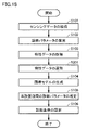
- FIG. 6 is a flowchart showing a processing procedure in the adjusted state of the state monitoring system of the first embodiment. The transition to the non-installed state due to removal can be performed at any time during the adjustment state, so it is not described in these flowcharts.
- the adjustment state processing procedure of a general condition monitoring system includes steps S101, S102, and S106.
- the procedure for processing the adjusted state of the state monitoring system of the present embodiment includes steps S101 to S106.
- the sensing data input unit 906 collects sensing data representing the state of the monitored device 101 output from the sensor 905 installed in the monitored device 101 during the adjustment period (data). measurement).
- the sensing data of the sensor 905 is, for example, data of an acceleration sensor, a current sensor, a voltmeter, a color sensor, an azimuth sensor, a wind speed sensor, a flow rate sensor, a pressure sensor, or a proximity sensor.
- the diagnostic parameter calculation unit 907 calculates the diagnostic parameter in the adjustment period based on the sensing data in the adjustment period.
- the diagnostic parameters are not only the detection data of the sensor 905 itself, but also the effective value, modulation value, average value, median value, sharpness, distortion, and other statistics of the detection data of the sensor 905, and the current value multiplied by the rated voltage. It is a physical quantity such as the amount of electric power obtained in the above process, the time difference between the inputs of the proximity sensors installed at a plurality of locations of the conveyor included in the monitored device 101, and the speed of the conveyed object obtained from the distance between these proximity sensors. ..
- the characteristic data input unit 104 acquires characteristic data representing the characteristics of the monitored device 101 during the non-installation period and the adjustment period from the logger 103 included in the monitored device 101.
- the characteristic data of the monitored device 101 includes pressure, temperature, rotation speed, current value, flow rate, maintenance information, and the like of the monitored device.
- the characteristic data when the monitored device 101 is a wind power generation facility includes wind direction, wind speed, weather, atmospheric pressure, and the like.
- the characteristic data of the machine tool whose monitored device 101 is a machine tool includes a type of machined product, a type of machining process, tool information, a type of material, and the like.
- the regression model generation unit 105 generates a regression model showing the relationship between the characteristic data and the diagnostic parameters by using the characteristic data in the adjustment period and the diagnostic parameters in the adjustment period.
- the regression model is various neural networks such as a simple regression model (single regression equation), a multiple regression model (multiple regression equation), a feedforward neural network, or an RBF (Radial Basis Function) network.
- step S105 the diagnostic parameter estimation unit 106 estimates the diagnostic parameters in the non-installed period corresponding to the characteristic data in the non-installed period using the regression model.
- the diagnostic standard setting unit 109 creates a diagnostic standard from basic data including the diagnostic parameter of the non-installed period and the diagnostic parameter of the adjustment period.
- Diagnostic criteria are thresholds, or adjusted neural networks.
- the threshold value is, for example, a value obtained by adding a constant multiple (for example, 3 times) of the standard deviation of the basic data to the average value of the basic data.
- step S101 the sensing data input unit 906 collects vibration data representing the vibration state of the monitored device 101 output from the vibration sensor installed in the monitored device 101 during the adjustment period.
- step S102 the diagnostic parameter calculation unit 907 calculates the effective vibration value in the adjustment period as a diagnostic parameter from the vibration data in the adjustment period.
- step S103 the characteristic data input unit 104 determines from the logger 103 included in the monitored device 101 the characteristics of the wind power generation facility the spindle rotation speed stored in the control device of the wind power generation facility during the non-installation period and the adjustment period. Get as data.
- step S104 the regression model generation unit 105 uses the characteristic data (spindle rotation speed) in the adjustment period and the diagnostic parameter (vibration effective value) in the adjustment period to represent a quadratic polynomial representing the relationship between the characteristic data and the diagnostic parameter. Generate a regression model.
- step S105 the diagnostic parameter estimation unit 106 estimates the diagnostic parameters (vibration effective value) in the non-installed period corresponding to the characteristic data (spindle rotation speed) in the non-installed period by using the quadratic polynomial regression model.
- the diagnostic standard setting unit 909 creates a diagnostic standard consisting of the first threshold value Th1 and the second threshold value Th2 from the basic data consisting of the vibration effective value in the non-installed period and the vibration effective value in the adjustment period. ..
- the first threshold value Th1 and the second threshold value Th2 are expressed as follows, where the standard deviation and the average of the basic data are ⁇ and ⁇ , respectively.
- Th1 ⁇ + a ⁇ ⁇ ... (1)
- Th2 ⁇ + a ⁇ ⁇ ⁇ n ... (2)
- FIG. 7 is a diagram showing the transition of diagnostic parameters after the installation of the condition monitoring device. It is assumed that a condition monitoring device is installed on 8/1.
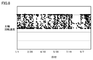
- FIG. 8 is a diagram showing data of the spindle rotation speed of the wind power generation facility stored in SCADA. For one month (8/1 to 9/1) after the condition monitoring device was installed, the spindle speed of the windmill continued to be low, and only the effective vibration value (diagnostic parameter) when the spindle speed was low could be measured. .. Therefore, in the general method, there is a problem that the correct diagnostic standard cannot be set unless the vibration data is measured by the vibration sensor for one month or more after the condition monitoring device is installed.
- FIG. 9 is a diagram showing changes in diagnostic parameters during the adjustment period in the first embodiment.
- One month (8/1 to 9/1) after the installation of the condition monitoring device is set as the adjustment period, and the vibration effective value, which is a diagnostic parameter, is calculated from the sensing data of the sensor 905 in this adjustment period.
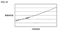
- FIG. 10 is a diagram showing a quadratic polynomial regression model in the first embodiment.
- the spindle rotation speed (characteristic data) is used by using a set of the effective vibration value (diagnosis parameter) and the spindle rotation speed (characteristic data) during the adjustment period, which is one month (8/1 to 9/1) after the installation of the state monitoring device.
- a quadratic polynomial regression model that estimates the effective vibration value (diagnosis parameter) from the characteristic data) is generated. Since the spindle speed is low during the adjustment period, a quadratic polynomial regression model is generated from the low spindle speed and the corresponding vibration effective value.
- FIG. 11 is a diagram showing estimated diagnostic parameters.
- the effective vibration value (diagnostic parameter) corresponding to the spindle speed (characteristic data) during the non-installation period can be obtained.
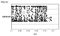
- FIG. 12 is a diagram showing an example of basic data.
- Effective vibration value (diagnostic parameter) calculated from the sensing data of the vibration sensor during the adjustment period, and effective vibration value estimated from the spindle rotation speed (characteristic data) using a quadratic polynomial regression model during the non-installation period. (Diagnostic parameters) is the basic data.
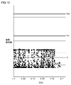
- FIG. 13 is a diagram showing an example of basic data and diagnostic criteria. As shown in FIG. 13, a first threshold value Th1 and a second threshold value Th2, which are diagnostic criteria, are set from the basic data. As described above, in the present embodiment, the diagnostic criteria can be set and the state can be changed to the operation state one month after the state monitoring device is installed.
- FIG. 14 is a diagram showing an example of basic data and diagnostic parameters during the operation period.
- the operation period will start on 9/1.
- the diagnosis is effective by comparing the effective vibration value (diagnosis parameter) obtained from the sensing data of the vibration sensor with the first threshold value Th1 and the second threshold value Th2 during the operation period.
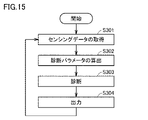
- FIG. 15 is a flowchart showing a processing procedure in an operating state in the state monitoring system of the first embodiment.
- transition to non-installation due to removal and the transition to adjustment due to state change can be performed at any time in the operating state, so it is not described in the flowchart. Furthermore, since the operational status is continued unless it is removed or the status is changed, the end of the flowchart is not described.
- step S301 during the operation period, the sensing data input unit 906 collects sensing data representing the state of the monitored device 101 output from the sensor 905 installed in the monitored device 101.
- step S302 the diagnostic parameter calculation unit 907 calculates the diagnostic parameter in the operation period based on the sensing data in the operation period.
- step S303 the diagnostic unit 908 diagnoses the state of the monitored device 101 by analyzing the diagnostic parameters calculated in step S302 using the diagnostic criteria set in the adjustment period.
- step S304 the output unit 910 outputs the diagnosis result to the status display 903.
- the diagnostic method by the diagnostic unit 908 includes a method of diagnosing the state of the monitored device 101 by comparing the diagnostic parameters and the threshold value, a method of diagnosing by clusters classified by clustering the diagnostic parameters, and an adjusted neural network. There is a method of inputting diagnostic parameters to the network and using the output of the neural network as the diagnostic result.
- FIG. 16 is a flowchart showing a diagnosis procedure in the condition monitoring system of the first embodiment.
- step S501 when the diagnostic parameter (x) is equal to or less than the first threshold value (Th1), the process proceeds to step S503.
- step S503 When the diagnostic parameter (x) exceeds the first threshold value (Th1), the process proceeds to step S502.
- step S502 when the diagnostic parameter (x) is equal to or less than the second threshold value (Th2), the process proceeds to step S504.
- step S504. When the diagnostic parameter (x) exceeds the second threshold value (Th2), the process proceeds to step S505.
- step S503 the diagnostic unit 908 determines that the monitored device 101 is in the "normal state". "Normal” is a state in which there is no abnormality in the monitored device 101.
- step S504 the diagnostic unit 908 determines that the monitored device 101 is in the "inspection required state".
- the "inspection required state” is a state in which the monitored device 101 has some sign of abnormality and needs to be inspected.
- step S505 the diagnostic unit 908 determines that the monitored device 101 is in the "stop required state".
- the "stop required state” is a state in which the monitored device is damaged when the monitored device 101 is continuously operated.
- the accuracy of diagnosis can be maintained even if the adjustment period is shortened by utilizing the data existing in the control device or the like.
- the time lag between the installation of the condition monitoring device and the start of diagnosis can be reduced, so there is a possibility that an abnormality will occur before the diagnosis is started and the abnormality will be overlooked. Can be reduced.
- FIG. 17 is a diagram showing a configuration example of the condition monitoring system according to the second embodiment.
- the condition monitoring system in the second embodiment includes a characteristic data selection unit 107 in addition to the configuration of the condition monitoring system in the first embodiment, and includes a regression model generation unit 205 in place of the regression model generation unit 105.
- the characteristic data selection unit 107 selects characteristic data whose correlation coefficient with the diagnostic parameter in the second period is equal to or higher than the threshold value among the characteristic data in the plurality of second periods. For example, suppose that when the diagnostic parameter is the effective vibration value, the spindle rotation speed, the wind direction, and the air volume are obtained as characteristic data. In the characteristic data selection unit 107, the correlation coefficient between the spindle rotation speed in the second period and the effective vibration value in the second period is equal to or higher than the threshold value, and the wind direction in the second period and the effective vibration value in the second period are used. When the correlation coefficient of is less than the threshold value and the correlation coefficient between the air volume in the second period and the effective vibration value in the second period is less than the threshold value, the spindle rotation speed is selected.
- FIG. 18 is a flowchart showing a processing procedure of the adjustment state of the state monitoring system of the second embodiment. The difference between the flowchart of the second embodiment of FIG. 18 and the flowchart of the first embodiment of FIG. 6 is that the flowchart of the second embodiment of FIG. 18 includes step S201.
- the characteristic data selection unit 107 has characteristic data in which the correlation coefficient with the diagnostic parameter in the second period (adjustment period) is equal to or higher than the threshold value among the characteristic data in the plurality of second periods (adjustment period). Is selected and output to the regression model generation unit 205.
- FIG. 19 is a diagram showing a configuration example of the condition monitoring system according to the third embodiment.
- the condition monitoring system in the third embodiment includes a regression model evaluation unit 303 in addition to the configuration of the condition monitoring system in the second embodiment.
- the regression model evaluation unit 303 obtains the evaluation value of the regression model based on the evaluation index.
- the evaluation index is a correct answer rate, a precision rate, a recall rate, an F value, a root mean square error, a root mean square error, or a coefficient of determination.
- the sensing data input unit 906 acquires the sensing data
- the diagnostic parameter calculation unit 907 calculates the diagnostic parameters
- the characteristic data input unit 104 acquires the characteristic data
- the regression model is repeated.
- FIG. 20 is a flowchart showing a processing procedure of the adjustment state of the state monitoring system of the third embodiment.
- the flowchart of the third embodiment of FIG. 20 differs from the flowchart of the second embodiment of FIG. 18 in that the flowchart of the third embodiment of FIG. 20 includes step S401 after step S105. be.
- step S401 the regression model evaluation unit 303 obtains the evaluation value of the regression model based on the evaluation index.
- step S105 When the evaluation value of the regression model is equal to or higher than the predetermined value, the process proceeds to step S105. When the evaluation value of the regression model is less than a predetermined value, the process proceeds to step S101.
- the end time of the adjustment period can be appropriately determined by evaluating the performance of the regression model. By appropriately determining the end time of the adjustment period, it is possible to reduce the risk of unnecessarily lengthening the adjustment period and the risk of making a misdiagnosis by making the adjustment period shorter than the required period.
- condition monitoring system of the fourth embodiment has a function of modifying diagnostic criteria during the operation period.
- FIG. 21 is a flowchart showing a processing procedure of the operating state of the state monitoring system of the fourth embodiment.
- step S601 during the operation period, the sensing data input unit 906 collects sensing data representing the state of the monitored device 101 output from the sensor 905 installed in the monitored device 101.
- step S602 the diagnostic parameter calculation unit 907 calculates the diagnostic parameter in the operation period based on the sensing data in the operation period.
- step S603 the diagnostic unit 908 determines the status of the monitored device 101 by analyzing the diagnostic parameters calculated in step S602 using the diagnostic criteria set in the adjustment period or the diagnostic criteria modified in the operation period. Diagnose.
- step S604 the output unit 910 outputs the diagnosis result to the status display 903.
- step S605 the characteristic data input unit 104 acquires characteristic data representing the characteristics of the monitored device 101 during the operation period from the logger 103 included in the monitored device 101.
- step S606 the regression model generation unit 205 modifies the regression model representing the relationship between the characteristic data and the diagnostic parameters by using the characteristic data in the adjustment period and the operation period and the diagnostic parameters in the adjustment period and the operation period.
- step S607 the diagnostic parameter estimation unit 106 re-estimates the diagnostic parameters in the non-installed period corresponding to the characteristic data in the non-installed period using the modified regression model.
- step S608 the diagnostic standard setting unit 109 corrects the diagnostic standard from the basic data consisting of the diagnostic parameter of the non-installed period, the diagnostic parameter of the adjustment period, and the diagnostic parameter of the operating period.
Landscapes
- Physics & Mathematics (AREA)
- Engineering & Computer Science (AREA)
- General Physics & Mathematics (AREA)
- Automation & Control Theory (AREA)
- Artificial Intelligence (AREA)
- Evolutionary Computation (AREA)
- Mathematical Physics (AREA)
- Testing And Monitoring For Control Systems (AREA)
Abstract
Description
状態監視装置を設置してから、データに基づいて診断基準を設定する調整期間には、診断を実施することができない。したがって、調整期間は短い方が好ましい。
[第1の実施形態]
(状態監視システムの構成)
図1は、一般的な状態監視システムの構成例を表わす図である。図2は、第1の実施形態における状態監視システムの構成例を表わす図である。
図3は、第1の実施形態の状態監視システムの状態遷移を表わす図である。
未設置状態は、状態監視装置102が設置されておらず、状態監視装置102と監視対象機器101とが接続されていない状態である。
状態変化とは、状態監視装置102とその周辺の構成に変化があり、診断基準が不適切になることである。状態変化には、例えば、監視対象機器101のメンテナンス、またはセンサの交換などがある。状態変化によって、状態監視装置102は、運用状態から調整状態に移行する。
(調整データ)
図4は、一般的な状態監視システムにおけるデータの活用と、本実施の形態の状態監視システムにおけるデータの活用とを比較した図である。
図5は、一般的な状態監視システムの調整状態における処理手順を表わすフローチャートである。図6は、第1の実施形態の状態監視システムの調整状態における処理手順を表わすフローチャートである。撤去による未設置状態への遷移は、調整状態中のいつでも行えるため、これらのフローチャートには記載されていない。
調整の具体例として、監視対象機器101が風力発電設備の場合の一例を示す。風力発電設備内の増速機に振動センサが設置されている。
Th2=μ+a×σ×n… (2)
ただし、aは任意の実数、nは1より大きい任意の定数である。たとえば、a=3、n=2としてもよい。
図7は、状態監視装置の設置後の診断パラメータの推移を表わす図である。8/1に状態監視装置が設置されたとする。図8は、SCADAに保存されている風力発電設備の主軸回転速度のデータを表わす図である。状態監視装置の設置後1ヶ月間(8/1~9/1)では、風車の主軸回転数が低い状態が続き、主軸回転数の低いときの振動実効値(診断パラメータ)しか計測できていない。このため、一般的な方法では、状態監視装置の設置後1ヶ月以上、振動センサによる振動データの計測を行わなければ、正しい診断基準を設定できないという問題がある。
図15は、第1の実施形態の状態監視システムにおける運用状態における処理手順を表わすフローチャートである。
診断部908による診断の方法には、診断パラメータと閾値とを比較することによって、監視対象機器101の状態を診断する方法、診断パラメータをクラスタリングして分類されたクラスタによって診断する方法、調整済みニューラルネットワークへ診断パラメータを入力してニューラルネットワークの出力を診断結果とする方法などがある。
図17は、第2の実施形態における状態監視システムの構成例を表わす図である。
図18は、第2の実施形態の状態監視システムの調整状態の処理手順を表わすフローチャートである。図18の第2の実施形態のフローチャートが、図6の第1の実施形態のフローチャートと相違する点は、図18の第2の実施形態のフローチャートが、ステップS201を備える。
図19は、第3の実施形態における状態監視システムの構成例を表わす図である。
第4の実施形態の状態監視システムは、運用期間において、診断基準を修正する機能を有する。
Claims (8)
- 監視対象機器と接続可能な状態監視装置であって、前記監視対象機器が前記状態監視装置に接続される前の第1の期間と、前記監視対象機器が前記状態監視装置に接続された後であって、前記監視対象機器の異常の診断の調整段階の第2の期間と、前記監視対象機器が前記状態監視装置に接続された後であって、前記監視対象機器の異常の診断を実施する第3の期間とが設定され、前記状態監視装置は、
前記第2の期間および前記第3の期間において、前記監視対象機器に含まれるセンサから、前記監視対象機器の状態を表わすセンシングデータを取得するセンシングデータ入力部と、
前記第2の期間および前記第3の期間における前記センシングデータに基づいて、前記第2の期間および前記第3の期間における診断パラメータを算出する診断パラメータ算出部と、
前記監視対象機器に含まれるロガーから、前記第1の期間および前記第2の期間における前記監視対象機器の特性を表わす特性データを取得する特性データを取得する特性データ入力部と、
前記第2の期間における前記特性データおよび前記第2の期間における前記診断パラメータを用いて、前記特性データと前記診断パラメータとの関係を表わす回帰モデルを生成する回帰モデル生成部と、
前記回帰モデルを用いて、前記第1の期間における特性データに対応する前記第1の期間における診断パラメータを推定する診断パラメータ推定部と、
前記第1の期間および前記第2の期間における診断パラメータを用いて、診断基準を設定する診断基準設定部と、
前記第3の期間における診断パラメータと、前記診断基準とに基づいて、前記監視対象機器の異常を診断する診断部とを備えた、状態監視装置。 - 複数の前記第2の期間における前記特性データのうち、前記第2の期間における前記診断パラメータとの相関係数が閾値以上となる特性データを選別する特性データ選別部をさらに備え、
前記回帰モデル生成部は、選別された前記特性データを用いて、前記回帰モデルを生成する、請求項1記載の状態監視装置。 - 定められた評価指標に基づいて、前記生成された回帰モデルの評価値を求める回帰モデル評価部をさらに備え、
前記回帰モデルの評価値が予め定められた値に達するまで、前記センシングデータの取得、前記診断パラメータの算出、前記特性データの取得、および前記回帰モデルの生成が繰り返される、請求項1または2記載の状態監視装置。 - 前記監視対象機器は、風力発電設備であり、
前記センサは、振動センサであり、
前記診断パラメータは、振動実効値であり、
前記特性データは、主軸回転速度である、請求項1または3記載の状態監視装置。 - 前記診断基準設定部は、前記第1の期間および前記第2の期間における診断パラメータの平均値μと標準偏差σとに基づいて、以下の式に従って、第1の閾値Th1を含む診断基準を作成し、
Th1=μ+a×σ… (1)
ただし、aは任意の実数、
前記診断部は、前記第3の期間における診断パラメータが前記第1の閾値Th1以下のときに、前記監視対象機器が正常であると判定する、請求項1~4のいずれか1項に記載の状態監視装置。 - 前記診断基準設定部は、前記第1の期間および前記第2の期間における診断パラメータの平均値μと標準偏差σとに基づいて、以下の式に従って、第2の閾値Th2をさらに含む診断基準を作成し、
Th2=μ+a×σ×n… (2)
ただし、aは任意の実数、nは1より大きい任意の定数、
前記診断部は、前記第3の期間における診断パラメータが前記第1の閾値を超え、前記第2の閾値以下のときに、前記監視対象機器が要点検状態であると判定する、請求項5記載の状態監視装置。 - 前記診断部は、前記第3の期間における診断パラメータが前記第2の閾値を超えるときに、前記監視対象機器が要停止状態であると判定する、請求項6記載の状態監視装置。
- 監視対象機器と接続可能な状態監視装置における状態監視方法であって、前記監視対象機器が前記状態監視装置に接続される前の第1の期間と、前記監視対象機器が前記状態監視装置に接続された後であって、前記監視対象機器の異常の診断の準備段階の第2の期間と、前記監視対象機器が前記状態監視装置に接続された後であって、前記監視対象機器の異常の診断を実施する第3の期間とが設定され、前記状態監視方法は、
前記状態監視装置が、前記第2の期間において、前記監視対象機器に含まれるセンサから、前記監視対象機器の状態を表わすセンシングデータを取得するステップと、
前記状態監視装置が、前記第2の期間における前記センシングデータに基づいて、前記第2の期間おける診断パラメータを算出するステップと、
前記状態監視装置が、前記監視対象機器に含まれるロガーから、前記第1の期間および前記第2の期間における前記監視対象機器の特性を表わす特性データを取得する特性データを取得するステップと、
前記状態監視装置が、前記第2の期間における前記特性データおよび前記第2の期間における前記診断パラメータを用いて、前記特性データと前記診断パラメータとの関係を表わす回帰モデルを生成するステップと、
前記状態監視装置が、前記回帰モデルを用いて、前記第1の期間における特性データに対応する前記第1の期間における診断パラメータを推定するステップと、
前記状態監視装置が、前記第1の期間および前記第2の期間における診断パラメータを用いて、診断基準を設定するステップと、
前記状態監視装置が、前記第3の期間において、前記監視対象機器に含まれるセンサから、前記監視対象機器の状態を表わすセンシングデータを取得するステップと、
前記状態監視装置が、前記第3の期間における前記センシングデータに基づいて、前記第3の期間おける診断パラメータを算出するステップと、
前記状態監視装置が、前記第3の期間における診断パラメータと、前記診断基準とに基づいて、前記監視対象機器の異常を診断するステップとを備えた、状態監視方法。
Priority Applications (3)
| Application Number | Priority Date | Filing Date | Title |
|---|---|---|---|
| US18/026,099 US12619210B2 (en) | 2020-09-30 | 2021-09-27 | State-monitoring device and state-monitoring method |
| EP21875491.9A EP4224263B1 (en) | 2020-09-30 | 2021-09-27 | State-monitoring device and state-monitoring method |
| CN202180064032.6A CN116075791B (zh) | 2020-09-30 | 2021-09-27 | 状态监视装置和状态监视方法 |
Applications Claiming Priority (2)
| Application Number | Priority Date | Filing Date | Title |
|---|---|---|---|
| JP2020165518A JP7471983B2 (ja) | 2020-09-30 | 2020-09-30 | 状態監視装置および状態監視方法 |
| JP2020-165518 | 2020-09-30 |
Publications (1)
| Publication Number | Publication Date |
|---|---|
| WO2022071189A1 true WO2022071189A1 (ja) | 2022-04-07 |
Family
ID=80949155
Family Applications (1)
| Application Number | Title | Priority Date | Filing Date |
|---|---|---|---|
| PCT/JP2021/035274 Ceased WO2022071189A1 (ja) | 2020-09-30 | 2021-09-27 | 状態監視装置および状態監視方法 |
Country Status (5)
| Country | Link |
|---|---|
| US (1) | US12619210B2 (ja) |
| EP (1) | EP4224263B1 (ja) |
| JP (1) | JP7471983B2 (ja) |
| CN (1) | CN116075791B (ja) |
| WO (1) | WO2022071189A1 (ja) |
Families Citing this family (1)
| Publication number | Priority date | Publication date | Assignee | Title |
|---|---|---|---|---|
| CN119472563B (zh) * | 2025-01-14 | 2025-04-15 | 杭州赛微电机有限公司 | 电机装配生产线的运转监控系统及方法 |
Citations (6)
| Publication number | Priority date | Publication date | Assignee | Title |
|---|---|---|---|---|
| JP2004133553A (ja) * | 2002-10-08 | 2004-04-30 | Toshiba Corp | 設備診断装置 |
| JP2013185507A (ja) | 2012-03-08 | 2013-09-19 | Ntn Corp | 状態監視システム |
| JP2013242637A (ja) * | 2012-05-18 | 2013-12-05 | Ihi Corp | 異常診断方法及び異常診断装置 |
| JP2015103218A (ja) * | 2013-11-28 | 2015-06-04 | 株式会社日立製作所 | プラントの診断装置及び診断方法 |
| JP2016062258A (ja) * | 2014-09-17 | 2016-04-25 | インターナショナル・ビジネス・マシーンズ・コーポレーションInternational Business Machines Corporation | 検出装置、検出方法、およびプログラム |
| JP2017181138A (ja) * | 2016-03-29 | 2017-10-05 | 一般財団法人電力中央研究所 | 太陽光発電設備の異常診断方法、異常診断装置、及び異常診断プログラム |
Family Cites Families (17)
| Publication number | Priority date | Publication date | Assignee | Title |
|---|---|---|---|---|
| JP2008230781A (ja) * | 2007-03-20 | 2008-10-02 | Toshiba Elevator Co Ltd | エレベータの診断システム |
| US8301333B2 (en) * | 2010-03-24 | 2012-10-30 | GM Global Technology Operations LLC | Event-driven fault diagnosis framework for automotive systems |
| WO2012009804A1 (en) * | 2010-07-23 | 2012-01-26 | Corporation De L'ecole Polytechnique | Tool and method for fault detection of devices by condition based maintenance |
| EP2810134B1 (en) | 2012-02-01 | 2016-06-01 | ABB Research Ltd. | Monitoring of primary devices in a power system |
| CN104160145B (zh) | 2012-03-08 | 2017-06-13 | Ntn株式会社 | 状态监视系统 |
| US10181101B2 (en) * | 2012-12-17 | 2019-01-15 | Arizona Board Of Regents On Behalf Of Arizona State University | Support vector machine enhanced models for short-term wind farm generation forecasting |
| CN105900022A (zh) | 2013-11-27 | 2016-08-24 | 精通人工智能系统有限公司 | 使用概率介质的基于人工智能模型的动态过程控制的方法和系统 |
| CN103761372B (zh) | 2014-01-06 | 2018-02-02 | 上海海事大学 | 一种基于主元分析与多分类相关向量机的多电平逆变器故障诊断策略 |
| JP6374234B2 (ja) | 2014-06-24 | 2018-08-15 | Ntn株式会社 | 状態監視システム及びそれを備えた風力発電システム |
| FI3221579T3 (fi) * | 2014-11-18 | 2023-06-21 | Hitachi Energy Switzerland Ag | Tuuliturbiinin tilan valvontamenetelmä ja -järjestelmä |
| CN107820540B (zh) * | 2015-06-30 | 2020-03-17 | 维斯塔斯风力系统集团公司 | 基于预测的风力涡轮机控制 |
| CN108136587B (zh) | 2015-09-25 | 2021-12-14 | Ntn株式会社 | 连杆操作装置的诊断装置 |
| DK3464895T3 (da) * | 2016-05-23 | 2022-01-17 | Gen Electric | System og fremgangsmåde til effektudgangprognosticering for en vindmøllepark |
| EP3336634B1 (en) * | 2016-12-14 | 2020-02-26 | ABB Schweiz AG | Computer system and method for monitoring the status of a technical system |
| CN108869173B (zh) * | 2018-01-31 | 2019-08-16 | 北京金风科创风电设备有限公司 | 风电机组的功率控制方法和设备 |
| JP7113668B2 (ja) | 2018-06-08 | 2022-08-05 | Ntn株式会社 | 状態監視システム |
| US11859846B2 (en) * | 2018-06-15 | 2024-01-02 | Johnson Controls Tyco IP Holdings LLP | Cost savings from fault prediction and diagnosis |
-
2020
- 2020-09-30 JP JP2020165518A patent/JP7471983B2/ja active Active
-
2021
- 2021-09-27 EP EP21875491.9A patent/EP4224263B1/en active Active
- 2021-09-27 CN CN202180064032.6A patent/CN116075791B/zh active Active
- 2021-09-27 WO PCT/JP2021/035274 patent/WO2022071189A1/ja not_active Ceased
- 2021-09-27 US US18/026,099 patent/US12619210B2/en active Active
Patent Citations (6)
| Publication number | Priority date | Publication date | Assignee | Title |
|---|---|---|---|---|
| JP2004133553A (ja) * | 2002-10-08 | 2004-04-30 | Toshiba Corp | 設備診断装置 |
| JP2013185507A (ja) | 2012-03-08 | 2013-09-19 | Ntn Corp | 状態監視システム |
| JP2013242637A (ja) * | 2012-05-18 | 2013-12-05 | Ihi Corp | 異常診断方法及び異常診断装置 |
| JP2015103218A (ja) * | 2013-11-28 | 2015-06-04 | 株式会社日立製作所 | プラントの診断装置及び診断方法 |
| JP2016062258A (ja) * | 2014-09-17 | 2016-04-25 | インターナショナル・ビジネス・マシーンズ・コーポレーションInternational Business Machines Corporation | 検出装置、検出方法、およびプログラム |
| JP2017181138A (ja) * | 2016-03-29 | 2017-10-05 | 一般財団法人電力中央研究所 | 太陽光発電設備の異常診断方法、異常診断装置、及び異常診断プログラム |
Non-Patent Citations (1)
| Title |
|---|
| See also references of EP4224263A4 |
Also Published As
| Publication number | Publication date |
|---|---|
| EP4224263A1 (en) | 2023-08-09 |
| JP7471983B2 (ja) | 2024-04-22 |
| US20230367283A1 (en) | 2023-11-16 |
| JP2022057324A (ja) | 2022-04-11 |
| CN116075791A (zh) | 2023-05-05 |
| US12619210B2 (en) | 2026-05-05 |
| CN116075791B (zh) | 2025-11-07 |
| EP4224263A4 (en) | 2024-10-30 |
| EP4224263B1 (en) | 2025-09-24 |
Similar Documents
| Publication | Publication Date | Title |
|---|---|---|
| EP3638900B1 (en) | Independent monitoring system for a wind turbine | |
| CN112784373B (zh) | 一种风电机组齿轮箱的故障预警方法 | |
| US10527520B2 (en) | Operating wind motors and determining their remaining useful life | |
| US11521105B2 (en) | Machine learning device and machine learning method for learning fault prediction of main shaft or motor which drives main shaft, and fault prediction device and fault prediction system including machine learning device | |
| US7200520B2 (en) | Device and method for monitoring an electric power station | |
| WO2018044507A1 (en) | Machine learning-aided model-based method for estimating gas turbine component life | |
| CN112257943A (zh) | 一种基于mset和偏离度的电厂引风机故障预警方法 | |
| KR102068643B1 (ko) | 풍력발전기 예지방법 | |
| JP7330754B2 (ja) | 異常診断装置及び方法 | |
| WO2017138238A1 (ja) | 監視装置及び監視装置の制御方法 | |
| JP2017142624A (ja) | 監視装置及び監視装置の制御方法 | |
| CN118013468B (zh) | 一种风电机组部件健康度监测方法、装置、设备及介质 | |
| EP3936957B1 (en) | Error-based method for calculating a remaining useful life of an apparatus | |
| JP7471983B2 (ja) | 状態監視装置および状態監視方法 | |
| US11339763B2 (en) | Method for windmill farm monitoring | |
| Rodríguez-López et al. | Development of indicators for the detection of equipment malfunctions and degradation estimation based on digital signals (alarms and events) from operation SCADA | |
| US20220004176A1 (en) | Method and control system for detecting condition of plurality of process equipment in industrial plant | |
| CN117589444B (zh) | 一种基于联邦学习的风力发电机齿轮箱故障诊断方法 | |
| US20250242713A1 (en) | Startup condition monitoring system for a machine | |
| Zhang | Comparison of data-driven and model-based methodologies of wind turbine fault detection with SCADA data | |
| KR102842755B1 (ko) | 기계의 상태감시데이터 경향성 진단을 이용한 수명예측방법 | |
| CN115962100A (zh) | 一种风电机组状态监测系统 | |
| KR102385534B1 (ko) | 데이터 간 상호 유사도에 기반한 가상수명데이터 생성장치 및 방법 |
Legal Events
| Date | Code | Title | Description |
|---|---|---|---|
| 121 | Ep: the epo has been informed by wipo that ep was designated in this application |
Ref document number: 21875491 Country of ref document: EP Kind code of ref document: A1 |
|
| NENP | Non-entry into the national phase |
Ref country code: DE |
|
| ENP | Entry into the national phase |
Ref document number: 2021875491 Country of ref document: EP Effective date: 20230502 |
|
| WWG | Wipo information: grant in national office |
Ref document number: 2021875491 Country of ref document: EP |
|
| WWG | Wipo information: grant in national office |
Ref document number: 202180064032.6 Country of ref document: CN |