WO2022071234A1 - 端末装置、通信方法、および基地局装置 - Google Patents
端末装置、通信方法、および基地局装置 Download PDFInfo
- Publication number
- WO2022071234A1 WO2022071234A1 PCT/JP2021/035419 JP2021035419W WO2022071234A1 WO 2022071234 A1 WO2022071234 A1 WO 2022071234A1 JP 2021035419 W JP2021035419 W JP 2021035419W WO 2022071234 A1 WO2022071234 A1 WO 2022071234A1
- Authority
- WO
- WIPO (PCT)
- Prior art keywords
- bwp
- rrc
- terminal device
- mac
- scg
- Prior art date
- Legal status (The legal status is an assumption and is not a legal conclusion. Google has not performed a legal analysis and makes no representation as to the accuracy of the status listed.)
- Ceased
Links
Images







Classifications
-
- H—ELECTRICITY
- H04—ELECTRIC COMMUNICATION TECHNIQUE
- H04W—WIRELESS COMMUNICATION NETWORKS
- H04W52/00—Power management, e.g. Transmission Power Control [TPC] or power classes
- H04W52/04—Transmission power control [TPC]
- H04W52/30—Transmission power control [TPC] using constraints in the total amount of available transmission power
- H04W52/36—Transmission power control [TPC] using constraints in the total amount of available transmission power with a discrete range or set of values, e.g. step size, ramping or offsets
- H04W52/365—Power headroom reporting
-
- H—ELECTRICITY
- H04—ELECTRIC COMMUNICATION TECHNIQUE
- H04L—TRANSMISSION OF DIGITAL INFORMATION, e.g. TELEGRAPHIC COMMUNICATION
- H04L5/00—Arrangements affording multiple use of the transmission path
- H04L5/003—Arrangements for allocating sub-channels of the transmission path
- H04L5/0032—Distributed allocation, i.e. involving a plurality of allocating devices, each making partial allocation
-
- H—ELECTRICITY
- H04—ELECTRIC COMMUNICATION TECHNIQUE
- H04L—TRANSMISSION OF DIGITAL INFORMATION, e.g. TELEGRAPHIC COMMUNICATION
- H04L5/00—Arrangements affording multiple use of the transmission path
- H04L5/0091—Signalling for the administration of the divided path, e.g. signalling of configuration information
- H04L5/0096—Indication of changes in allocation
- H04L5/0098—Signalling of the activation or deactivation of component carriers, subcarriers or frequency bands
-
- H—ELECTRICITY
- H04—ELECTRIC COMMUNICATION TECHNIQUE
- H04L—TRANSMISSION OF DIGITAL INFORMATION, e.g. TELEGRAPHIC COMMUNICATION
- H04L5/00—Arrangements affording multiple use of the transmission path
- H04L5/0001—Arrangements for dividing the transmission path
- H04L5/0003—Two-dimensional division
- H04L5/0005—Time-frequency
- H04L5/0007—Time-frequency the frequencies being orthogonal, e.g. OFDM(A) or DMT
- H04L5/001—Time-frequency the frequencies being orthogonal, e.g. OFDM(A) or DMT the frequencies being arranged in component carriers
-
- H—ELECTRICITY
- H04—ELECTRIC COMMUNICATION TECHNIQUE
- H04L—TRANSMISSION OF DIGITAL INFORMATION, e.g. TELEGRAPHIC COMMUNICATION
- H04L5/00—Arrangements affording multiple use of the transmission path
- H04L5/0001—Arrangements for dividing the transmission path
- H04L5/0014—Three-dimensional division
- H04L5/0023—Time-frequency-space
-
- H—ELECTRICITY
- H04—ELECTRIC COMMUNICATION TECHNIQUE
- H04L—TRANSMISSION OF DIGITAL INFORMATION, e.g. TELEGRAPHIC COMMUNICATION
- H04L5/00—Arrangements affording multiple use of the transmission path
- H04L5/003—Arrangements for allocating sub-channels of the transmission path
- H04L5/0048—Allocation of pilot signals, i.e. of signals known to the receiver
-
- H—ELECTRICITY
- H04—ELECTRIC COMMUNICATION TECHNIQUE
- H04L—TRANSMISSION OF DIGITAL INFORMATION, e.g. TELEGRAPHIC COMMUNICATION
- H04L5/00—Arrangements affording multiple use of the transmission path
- H04L5/003—Arrangements for allocating sub-channels of the transmission path
- H04L5/0053—Allocation of signalling, i.e. of overhead other than pilot signals
- H04L5/0057—Physical resource allocation for CQI
-
- H—ELECTRICITY
- H04—ELECTRIC COMMUNICATION TECHNIQUE
- H04L—TRANSMISSION OF DIGITAL INFORMATION, e.g. TELEGRAPHIC COMMUNICATION
- H04L5/00—Arrangements affording multiple use of the transmission path
- H04L5/14—Two-way operation using the same type of signal, i.e. duplex
-
- H—ELECTRICITY
- H04—ELECTRIC COMMUNICATION TECHNIQUE
- H04W—WIRELESS COMMUNICATION NETWORKS
- H04W52/00—Power management, e.g. Transmission Power Control [TPC] or power classes
- H04W52/04—Transmission power control [TPC]
- H04W52/30—Transmission power control [TPC] using constraints in the total amount of available transmission power
- H04W52/34—TPC management, i.e. sharing limited amount of power among users or channels or data types, e.g. cell loading
-
- Y—GENERAL TAGGING OF NEW TECHNOLOGICAL DEVELOPMENTS; GENERAL TAGGING OF CROSS-SECTIONAL TECHNOLOGIES SPANNING OVER SEVERAL SECTIONS OF THE IPC; TECHNICAL SUBJECTS COVERED BY FORMER USPC CROSS-REFERENCE ART COLLECTIONS [XRACs] AND DIGESTS
- Y02—TECHNOLOGIES OR APPLICATIONS FOR MITIGATION OR ADAPTATION AGAINST CLIMATE CHANGE
- Y02D—CLIMATE CHANGE MITIGATION TECHNOLOGIES IN INFORMATION AND COMMUNICATION TECHNOLOGIES [ICT], I.E. INFORMATION AND COMMUNICATION TECHNOLOGIES AIMING AT THE REDUCTION OF THEIR OWN ENERGY USE
- Y02D30/00—Reducing energy consumption in communication networks
- Y02D30/70—Reducing energy consumption in communication networks in wireless communication networks
Definitions
- the present invention relates to a terminal device, a communication method, and a base station device.
- the present application claims priority with respect to Japanese Patent Application No. 2020-165020 filed in Japan on September 30, 2020, the contents of which are incorporated herein by reference.
- 3GPP 3rd Generation Partnership Project
- E-UTRA EvolvedUniversaLTErrestrialRadioAccess
- RAT Radio Access Technology
- LTE-A LongTermEvolution
- LTE-APro LTE-AdvancedPro
- NR New Radio or NR Radio access
- RAT Radio Access Technology
- NR As an extension technology of NR, there is a dual connectivity (also called multi-connectivity) technology in which one or more base station devices and terminal devices communicate with each other using a plurality of cell groups in order to enable large-capacity data communication. ..
- the terminal device in order to communicate in each cell group, the terminal device needs to monitor the presence or absence of a message addressed to itself in each cell group.
- the terminal device needs to constantly monitor a plurality of cell groups so that communication can be performed with low delay when a large amount of data communication occurs, which causes a problem of consuming a large amount of power. Therefore, a technique for monitoring or stopping some cell groups infrequently (cell group dormant technique) has been started.
- SpCell cells that are always active at present
- One aspect of the present invention has been made in view of the above circumstances, and one of the objects is to provide a terminal device, a communication method, and a base station device capable of efficiently performing communication control.
- one aspect of the present invention is a terminal device in which a first cell group and a second cell group are set, and a processing unit that triggers a power headroom report (PHR) and the triggered PHR.
- the PHR is a terminal device that includes a transmission unit that transmits to the base station device and is triggered by the processing unit based on the activation of the second cell group.
- one aspect of the present invention is a communication method applied to a terminal device in which a first cell group and a second cell group are set, and triggers a power headroom report (PHR).
- the PHR is transmitted to the base station apparatus, and the PHR is a communication method triggered by activation of the second cell group.
- One aspect of the present invention is a base station device that sets a first cell group and a second cell group in a terminal device, and includes a receiving unit that receives a power headroom report (PHR) from the terminal device.
- the PHR is a base station device triggered by the terminal device based on the activation of the second cell group.
- one aspect of the present invention is a communication method applied to a base station device in which a first cell group and a second cell group are set in a terminal device, and a power headroom report (PHR) is obtained from the terminal device.
- PHR is a communication method triggered by the terminal device based on the activation of the second cell group.
- the terminal device, the base station device, the method, and the integrated circuit can realize efficient communication control processing.
- the schematic diagram of the communication system which concerns on embodiment of this invention.
- the figure of an example of the E-UTRA protocol composition which concerns on embodiment of this invention.
- the figure of an example of the NR protocol composition which concerns on embodiment of this invention.
- the figure which shows an example of the flow of the procedure for various setting in RRC which concerns on embodiment of this invention.
- the block diagram which shows the structure of the terminal apparatus in embodiment of this invention.
- the block diagram which shows the structure of the base station apparatus in embodiment of this invention.
- An example of the ASN.1 description contained in the message regarding the resetting of the RRC connection in E-UTRA in the embodiment of the present invention.
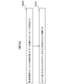
- An example of the process relating to dormancy of SCG in the embodiment of the present invention An example of the treatment relating to the activation of SCG in the embodiment of the present invention.
- An example of the treatment relating to the inactivation of SCG in the embodiment of the present invention An example of processing relating to PHR in the embodiment of the present invention.
- LTE and LTE-A, LTE-APro
- NR may be defined as different radio access technologies (RadioAccess Technology: RAT).
- RAT RadioAccess Technology: RAT
- NR may also be defined as a technology included in LTE.
- LTE may also be defined as a technology included in NR.
- LTE that can be connected to NR by MultiRadio Dual connectivity (MR-DC) may be distinguished from conventional LTE.
- MR-DC MultiRadio Dual connectivity
- LTE using 5GC for the core network may be distinguished from conventional LTE using EPC for the core network.
- the conventional LTE may be LTE that does not implement the technology standardized after Release 15 in 3GPP.
- Embodiments of the present invention may be applied to NR, LTE and other RATs.
- LTE Long Term Evolution
- NR Long Term Evolution
- E-UTRA in the embodiment of the present invention may be replaced with the term LTE
- LTE may be replaced with the term E-UTRA
- the names of the nodes and entities when the wireless access technology is E-UTRA or NR, the processing in each node and the entity, and the like will be described. It may be used for other wireless access technologies.
- the name of each node or entity in the embodiment of the present invention may be another name.
- FIG. 1 is a schematic diagram of a communication system according to an embodiment of the present invention.
- the functions of each node, wireless access technology, core network, interface, etc. described with reference to FIG. 1 are some functions closely related to the embodiment of the present invention, and may have other functions.
- E-UTRA100 may be a wireless access technology. Further, the E-UTRA 100 may be an air interface between the UE 122 and the eNB 102. The air interface between the UE 122 and the eNB 102 may be referred to as a Uu interface.
- the eNB (E-UTRAN Node B) 102 may be a base station device of the E-UTRA100.
- the eNB 102 may have the E-UTRA protocol described later.
- the E-UTRA protocol may be composed of an E-UTRA user plane (User Plane: UP) protocol described later and an E-UTRA control plane (CP) protocol described later.
- the eNB 102 may terminate the E-UTRA user plane (User Plane: UP) protocol and the E-UTRA control plane (CP) protocol for the UE 122.
- a radio access network composed of eNB may be called E-UTRAN.
- the EPC (Evolved Packet Core) 104 may be a core network.
- the interface 112 is an interface between the eNB 102 and the EPC 104 and may be referred to as the S1 interface.
- the interface 112 may include a control plane interface through which control signals pass and / or a user plane interface through which (and / or) user data passes.
- the control plane interface of the interface 112 may be terminated by the Mobility Management Entity (MME: not shown) in the EPC 104.
- MME Mobility Management Entity
- the user plane interface of the interface 112 may be terminated by a serving gateway (S-GW: not shown) in the EPC 104.
- S-GW serving gateway
- the control plane interface of the interface 112 may be referred to as an S1-MME interface.
- the user plane interface of the interface 112 may be referred to as an S1-U interface.
- one or more eNBs 102 may be connected to the EPC 104 via the interface 112.
- An interface may exist between the plurality of eNBs 102 connected to the EPC 104 (not shown).
- the interface between a plurality of eNBs 102 connected to the EPC 104 may be referred to as an X2 interface.
- the NR106 may be a wireless access technology. Further, the NR 106 may be an air interface between the UE 122 and the gNB 108. The air interface between the UE 122 and the gNB 108 may be referred to as the Uu interface.
- the gNB (g Node B) 108 may be a base station device of NR106.
- the gNB 108 may have the NR protocol described below.
- the NR protocol may be composed of the NR user plane (User Plane: UP) protocol described later and the NR control plane (Control Plane: CP) protocol described later.
- the gNB 108 may terminate the NR user plane (User Plane: UP) protocol and the NR control plane (CP) protocol for the UE 122.
- the 5GC110 may be a core network.
- Interface 116 is an interface between gNB 108 and 5GC 110 and may be referred to as an NG interface.
- the interface 116 may include a control plane interface through which control signals pass and / or a user plane interface through which user data passes.
- the control plane interface of the interface 116 may be terminated by the Access and mobility Management Function (AMF: not shown) in the 5GC110.
- the user plane interface of the interface 116 may be terminated by the User Plane Function (UPF: not shown) in the 5GC110.
- the control plane interface of the interface 116 may be called an NG-C interface.
- the user plane interface of the interface 116 may be called an NG-U interface.
- one or more gNB 108 may be connected to the 5GC 110 via the interface 116.
- An interface may exist between the plurality of gNBs 108 connected to the 5GC110 (not shown).
- the interface between a plurality of gNB 108s connected to the 5GC110 may be referred to as an Xn interface.
- the eNB 102 may have a function of connecting to the 5GC110.
- the eNB 102 having a function of connecting to the 5GC110 may be referred to as an ng-eNB.
- the interface 114 is an interface between the eNB 102 and the 5GC110 and may be referred to as an NG interface.
- the interface 114 may include a control plane interface through which control signals pass and / or a user plane interface through which user data passes.
- the control plane interface of the interface 114 may be terminated by the Access and mobility Management Function (AMF: not shown) in the 5GC110.
- the user plane interface of the interface 114 may be terminated by the User Plane Function (UPF: not shown) in the 5GC110.
- AMF Access and mobility Management Function
- UPF User Plane Function
- the control plane interface of the interface 114 may be called an NG-C interface.
- the user plane interface of the interface 114 may be referred to as an NG-U interface.
- a radio access network composed of ng-eNB or gNB may be referred to as NG-RAN.
- NG-RAN, E-UTRAN, eNB, ng-eNB, gNB, etc. may be simply referred to as a network.
- one or more eNBs 102 may be connected to the 5GC110 via the interface 114.
- An interface may exist between the plurality of eNBs 102 connected to the 5GC110 (not shown).
- the interface between the plurality of eNBs 102 connected to the 5GC110 may be referred to as an Xn interface.
- the eNB 102 connected to the 5GC110 and the gNB108 connected to the 5GC110 may be connected by the interface 120.
- the interface 120 between the eNB 102 connected to the 5GC110 and the gNB108 connected to the 5GC110 may be referred to as an Xn interface.
- the gNB 108 may have a function of connecting to the EPC 104.
- the gNB 108 having a function of connecting to the EPC 104 may be referred to as an en-gNB.
- Interface 118 is an interface between gNB 108 and EPC 104 and may be referred to as an S1 interface.
- the interface 118 may have a user plane interface through which user data passes.
- the user plane interface of interface 118 may be terminated by S-GW (not shown) in EPC104.
- the user plane interface of interface 118 may be referred to as an S1-U interface.
- the eNB 102 connected to the EPC 104 and the gNB 108 connected to the EPC 104 may be connected by the interface 120.
- the interface 120 between the eNB 102 connected to the EPC 104 and the gNB 108 connected to the EPC 104 may be referred to as an X2 interface.
- the interface 124 is an interface between the EPC 104 and the 5GC110, and may be an interface through CP only, UP only, or both CP and UP. Further, some or all of the interfaces 114, the interface 116, the interface 118, the interface 120, the interface 124, and the like may not exist depending on the communication system provided by the telecommunications carrier or the like.
- the UE 122 may be a terminal device capable of receiving broadcast information and paging messages transmitted from the eNB 102 and / or the gNB 108. Further, the UE 122 may be a terminal device capable of wireless connection with the eNB 102 and / or the gNB 108. Further, the UE 122 may be a terminal device capable of making a wireless connection with the eNB 102 and a wireless connection with the gNB 108 at the same time. The UE 122 may have an E-UTRA protocol and / or an NR protocol.
- the wireless connection may be a RadioResourceControl (RRC) connection.
- RRC RadioResourceControl
- a wireless connection may be made by establishing a wireless bearer (RB: RadioBearer) between the UE 122 and the eNB 102 and / or the gNB 108.
- the radio bearer used for CP may be called a signaling radio bearer (SRB: Signaling Radio Bearer).
- the wireless bearer used for UP may be called a data wireless bearer (DRB Data Radio Bearer).
- a radio bearer identifier (Identity: ID) may be assigned to each radio bearer.
- the radio bearer identifier for SRB may be referred to as an SRB identifier (SRB Identity or SRB ID).
- the radio bearer identifier for DRB may be referred to as a DRB identifier (DRB Identity or DRB ID).
- the UE 122 may be a terminal device capable of being connected to the EPC 104 and / or the 5GC 110 via the eNB 102 and / or the gNB 108.
- the connection destination core network of the eNB 102 and / or the gNB 108 with which the UE 122 communicates is the EPC 104
- each DRB established between the UE 122 and the eNB 102 and / or the gNB 108 further passes through the EPC 104 and each EPS.
- EPS bearer may be identified by an EPS bearer identifier (Identity, or ID). Further, the same QoS may be guaranteed for data such as IP packets passing through the same EPS bearer and Ethernet (registered trademark) frames.
- each DRB established between the UE 122 and the eNB 102 and / or the gNB 108 is further established in the 5GC110. It may be linked to one of the PDU (PacketDataUnit) sessions. Each PDU session may have one or more QoS flows. Each DRB may be mapped to one or more QoS flows and may not be associated with any QoS flow. Each PDU session may be identified by a PDU session identifier (Identity, Identifier, or ID). Further, each QoS flow may be identified by a QoS flow identifier (Identity, Identifier, or ID). Further, the same QoS may be guaranteed for data such as IP packets and Ethernet frames that pass through the same QoS flow.
- PDU session identifier Identity, Identifier, or ID
- each QoS flow may be identified by a QoS flow identifier (Identity, Identifier, or ID). Further, the same QoS may be guaranteed for data such as IP packets and Ethernet frames that pass
- the EPC104 does not have to have a PDU session and / or a QoS flow. Further, the EPS bearer does not have to exist in the 5GC110.
- the UE 122 When the UE 122 is connected to the EPC 104, the UE 122 has information on the EPS bearer, but does not have to have the information in the PDU session and / or the QoS flow. Further, when the UE 122 is connected to the 5GC110, the UE 122 has the information in the PDU session and / or the QoS flow, but does not have to have the information of the EPS bearer.
- the eNB 102 and / or the gNB 108 are also simply referred to as a base station device, and the UE 122 is also simply referred to as a terminal device or a UE.
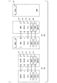
- FIG. 2 is a diagram of an example of the E-UTRA protocol configuration (protocol architecture) according to the embodiment of the present invention.
- FIG. 3 is a diagram of an example of the NR protocol configuration according to the embodiment of the present invention. It should be noted that the functions of the respective protocols described with reference to FIGS. 2 and / or 3 are some functions closely related to the embodiment of the present invention, and may have other functions.
- the uplink (UL) may be a link from the terminal device to the base station device.
- the downlink (DL) may be a link from the base station device to the terminal device.
- FIG. 2A is a diagram of the E-UTRA user plane (UP) protocol stack.
- the E-UTRANUP protocol may be a protocol between the UE 122 and the eNB 102. That is, the E-UTRANUP protocol may be a protocol terminated by eNB 102 on the network side.
- the E-UTRA user plane protocol stack includes a PHY (Physical layer) 200 which is a wireless physical layer (radio physical layer) and a MAC (Media) which is a medium access control layer (medium access control layer).
- PHY Physical layer
- MAC Media
- RLC Radio Link Control
- PDCP Packet Data Convergence Protocol
- packet data convergence protocol layer Packet data convergence protocol layer
- FIG. 3A is a diagram of the NR user plane (UP) protocol stack.
- the NRUP protocol may be a protocol between UE 122 and gNB 108. That is, the NRUP protocol may be a protocol terminated by gNB108 on the network side.
- the E-UTRA user plane protocol stack is a wireless physical layer PHY300, a medium access control layer MAC302, a wireless link control layer RLC304, and a packet data convergence protocol layer PDCP306.
- the service data adaptation protocol layer (service data adaptation protocol layer) SDAP (Service Data Adjustment Protocol) 310 may be configured.
- FIG. 2B is a diagram of the E-UTRA control plane (CP) protocol configuration.
- the RRC (Radio Resource Control) 208 which is a radio resource control layer (radio resource control layer)
- RRC208 may be a protocol terminated by eNB 102 on the network side.
- the NAS (Non Access Stratum) 210 which is a non-AS (Access Stratum) layer (non-AS layer)
- NAS210 may be a protocol terminated by MME on the network side.
- FIG. 3B is a diagram of the NR control plane (CP) protocol configuration.
- the radio resource control layer RRC308 may be a protocol between the UE 122 and the gNB 108. That is, RRC308 may be a protocol terminated by gNB108 on the network side.
- NAS312 which is a non-AS layer, may be a protocol between UE 122 and AMF. That is, NAS312 may be a protocol terminated by AMF on the network side.
- the AS (Access Stratum) layer may be a layer terminated between the UE 122 and the eNB 102 and / or the gNB 108. That is, the AS layer is a layer containing a part or all of PHY200, MAC202, RLC204, PDCP206, and RRC208, and / or a layer containing a part or all of PHY300, MAC302, RLC304, PDCP306, SDAP310, and RRC308. Good.
- the E-UTRA protocol and the NR protocol are not distinguished below, and PHY (PHY layer), MAC (MAC layer), RLC (RLC layer), PDCP (PDCP layer), RRC ( The terms RRC layer) and NAS (NAS layer) may be used.
- PHY PHY
- MAC MAC layer
- RLC RLC
- PDCP PDCP layer
- RRC RRC
- NAS NAS layer
- SDAP Secure Digital Protocol
- RLC RLC layer
- PDCP PDCP layer
- RRC RRC layer
- NAS NAS layer
- PHY PHY
- MAC MAC
- MAC MAC
- RLC RLC layer
- PDCP PDCP layer
- RRC RRC layer
- NAS NAS layer
- PHY PHY
- MAC MAC
- MAC MAC
- RLC RLC layer
- PDCP PDCP layer
- RRC RRC layer
- NAS NAS layer
- NAS NAS layer
- SDAP SDAP layer
- SDAP layer may be an SDAP (SDAP layer) of the NR protocol.
- the PHY200, MAC202, RLC204, PDCP206, and RRC208 are referred to as PHY for E-UTRA or PHY for LTE, E-UTRA, respectively.
- PHY200, MAC202, RLC204, PDCP206, and RRC208 are used as E-UTRA PHY or LTE PHY, E-UTRA MAC or LTE MAC, E-UTRA RLC or LTE RLC, E-UTRA PDCP or LTE PDCP, and E-UTRA, respectively. It may be described as RRC or LTE RRC.
- the PHY300, MAC302, RLC304, PDCP306, and RRC308 are referred to as PHY for NR, MAC for NR, RLC for NR, RLC for NR, and RRC for NR, respectively.
- PHY200, MAC302, RLC304, PDCP306, and RRC308 may be described as NRPHY, NRMAC, NRRLC, NRPDCP, NRRRC, etc., respectively.
- An entity that has some or all of the functions of the MAC layer may be called a MAC entity.
- An entity that has some or all of the functions of the RLC layer may be called an RLC entity.
- An entity that has some or all of the functions of the PDCP layer may be called a PDCP entity.
- An entity that has some or all of the functions of the SDAP layer may be called an SDAP entity.
- An entity that has some or all of the functions of the RRC layer may be called an RRC entity.
- the MAC entity, RLC entity, PDCP entity, SDAP entity, and RRC entity may be paraphrased as MAC, RLC, PDCP, SDAP, and RRC, respectively.
- the data provided from the lower layer to MAC, RLC, PDCP, SDAP and / or the data provided to MAC, RLC, PDCP, SDAP from the lower layer are referred to as MAC PDU (Protocol Data Unit) and RLC, respectively. It may be called PDU, PDCP PDU, SDAP PDU.
- the data provided from the upper layer to MAC, RLC, PDCP, SDAP and / or the data provided to the upper layer from MAC, RLC, PDCP, SDAP are referred to as MAC SDU (Service Data Unit) and RLC SDU, respectively.
- MAC SDU Service Data Unit
- RLC SDU Service Data Unit
- the segmented RLC SDU may be called the RLC SDU segment.
- the PHY of the terminal device may have a function of receiving data transmitted from the PHY of the base station device via the downlink (DL) physical channel (Physical Channel).
- the PHY of the terminal device may have a function of transmitting data to the PHY of the base station device via an uplink (UL) physical channel.
- the PHY may be connected to the upper MAC by a transport channel (TransportChannel).
- the PHY may pass data to the MAC over the transport channel.
- the PHY may also be provided with data from the MAC via the transport channel.
- RNTI Radio Network Temporary Identifier
- the physical channels used for wireless communication between the terminal device and the base station device may include the following physical channels.
- PBCH Physical Broadcast CHannel
- PDCCH Physical Downlink Control CHannel
- PDSCH Physical Downlink Shared CHannel
- PUCCH Physical Uplink Control CHannel
- PUSCH Physical Uplink Shared CHannel
- PRACH Physical Random Access CHannel
- PBCH may be used to inform the system information required by the terminal device.
- PBCH may be used to notify the time index (SSB-Index) within the period of the block of the synchronization signal (also referred to as SS / PBCH block).
- SSB-Index time index within the period of the block of the synchronization signal
- PDCCH may be used for transmitting (or carrying) downlink control information (Downlink Control Information: DCI) in downlink wireless communication (wireless communication from a base station device to a terminal device).
- DCI Downlink Control Information
- one or more DCIs (which may be referred to as DCI format) may be defined for the transmission of downlink control information. That is, the field for the downlink control information may be defined as DCI and mapped to the information bit.
- the PDCCH may be transmitted in the PDCCH candidate (candidate).
- the terminal device may monitor the set of PDCCH candidates in the serving cell. Monitoring a set of PDCCH candidates may mean attempting to decode the PDCCH according to a DCI format.
- the DCI format may be used for scheduling PUSCH in the serving cell.
- PUSCH may be used for sending user data, sending RRC messages described later, and the like.
- the PUCCH may be used to transmit uplink control information (UCI) in uplink wireless communication (wireless communication from a terminal device to a base station device).
- the uplink control information may include channel state information (CSI: Channel State Information) used to indicate the status of the downlink channel.
- the uplink control information may include a scheduling request (SR: Scheduling Request) used for requesting a UL-SCH (UL-SCH: Uplink Shared CHannel) resource.
- SR Scheduling Request
- UL-SCH Uplink Shared CHannel
- the uplink control information may include HARQ-ACK (Hybrid Automatic Repeat request ACKnowledgement).
- PDSCH may be used for transmission of downlink data (DL-SCH: Downlink Shared CHannel) from the MAC layer. Further, in the case of a downlink, it may be used for transmission of system information (SI: System Information) and random access response (RAR: Random Access Response).
- SI System Information
- RAR Random Access Response
- PUSCH may be used to transmit HARQ-ACK and / or CSI together with uplink data (UL-SCH: Uplink Shared CHannel) or uplink data from the MAC layer.
- PUSCH may also be used to transmit CSI only, or HARQ-ACK and CSI only. That is, PUSCH may be used to transmit only UCI.
- PDSCH or PUSCH may also be used to transmit RRC signaling (also referred to as RRC message) and MAC control elements.
- RRC signaling also referred to as RRC message
- the RRC signaling transmitted from the base station device may be a signal common to a plurality of terminal devices in the cell.
- the RRC signaling transmitted from the base station device may be dedicated signaling (also referred to as dedicated signaling) to a certain terminal device. That is, the information unique to the terminal device (UE specific) may be transmitted to a certain terminal device using a dedicated signaling.
- PUSCH may be used for transmission of UE Capability on the uplink.
- PRACH may be used to send a random access preamble.
- PRACH is to indicate initial connection establishment procedure, handover procedure, connection re-establishment procedure, synchronization (timing adjustment) for uplink transmission, and PUSCH (UL-SCH) resource request. May be used for.
- the MAC may be referred to as a MAC sublayer.
- the MAC may have a function of mapping various logical channels (logical channels: Logical Channels) to the corresponding transport channels.
- the logical channel may be identified by a logical channel identifier (LogicalChannelIdentity or LogicalChannelID).
- the MAC may be connected to the upper RLC by a logical channel (logical channel).
- the logical channel may be divided into a control channel for transmitting control information and a traffic channel for transmitting user information, depending on the type of information to be transmitted. Further, the logical channel may be divided into an uplink logical channel and a downlink logical channel.
- the MAC may have the function of multiplexing and providing the MAC SDU belonging to one or more different logical channels to the PHY.
- the MAC may also have a function of demultiplexing the MAC PDU provided by the PHY and providing it to the upper layer via the logical channel to which each MAC SDU belongs.
- the MAC may have a function of performing error correction through HARQ (Hybrid Automatic Repeat reQuest).
- the MAC may also have a scheduling report (SR) function that reports scheduling information.
- the MAC may have a function of performing priority processing between terminal devices by using dynamic scheduling. Further, the MAC may have a function of performing priority processing between logical channels in one terminal device.
- the MAC may have a function of prioritizing overlapping resources in one terminal device.
- the E-UTRA MAC may have a function to identify Multimedia Broadcast Multicast Services (MBMS). Further, the NR MAC may have a function of identifying a multicast / broadcast service (Multicast Broadcast Service: MBS). The MAC may have the ability to select a transport format. MAC has a function to perform intermittent reception (DRX: DiscontinuousReception) and / or intermittent transmission (DTX: DiscontinuousTransmission), a function to execute a random access (RandomAccess: RA) procedure, and a power to notify information on transmittable power.
- DRX DiscontinuousReception
- DTX DiscontinuousTransmission
- RA random access
- the NR MAC may have a headroom report (PowerHeadroomReport: PHR) function, a buffer status report (BufferStatusReport: BSR) function for notifying the data amount information of the transmission buffer, and the like.
- the NR MAC may have a Bandwidth Adaptation (BA) function.
- BA Bandwidth Adaptation
- the MAC PDU format used in E-UTRA MAC and the MAC PDU format used in NR MAC may be different.
- the MAC PDU may include a MAC control element (MAC control element: MACCE), which is an element for performing control in the MAC.
- MAC control element MAC control element
- UL Uplink
- DL Downlink
- BCCH Broadcast Control Channel
- SI System Information
- PCCH Packet Control Channel
- PCCH Packet Control Channel
- CCCH Common Control Channel
- CCCH may be a logical channel for transmitting control information between the terminal device and the base station device.
- CCCH may be used when the terminal device does not have an RRC connection.
- CCCH may also be used between a base station appliance and a plurality of terminal appliances.
- DCCH Dedicated Control Channel
- the dedicated control information may be control information dedicated to each terminal device.
- DCCH may be used when the terminal device has an RRC connection.
- the DTCH (Dedicated Traffic Channel) may be a logical channel for transmitting user data on a one-to-one basis (point-to-point) between the terminal device and the base station device.
- DTCH may be a logical channel for transmitting dedicated user data.
- the dedicated user data may be user data dedicated to each terminal device.
- DTCH may exist on both the uplink and the downlink.
- MTCH Multicast Traffic Channel
- MTCH may be a one-to-multipoint downlink channel for transmitting data from a base station device to a terminal device.
- MTCH may be a logical channel for multicast.
- MTCH may be used by the terminal device only if the terminal device receives MBMS.
- the MCCH may be a one-to-multipoint downlink channel for sending MBMS control information for one or more MTCHs from the base station device to the terminal device.
- MCCH may be a logical channel for multicast.
- MCCH may be used by a terminal device only when the terminal device receives MBMS or is interested in receiving MBMS.
- SC-MTCH Single Cell Multicast Traffic Channel
- SC-PTM Single Cell Point-To-Multipoint
- SC-MCCH Single Cell Multicast Control Channel
- SC-MCCH Single Cell Multicast Control Channel
- SC-MCCH Single Cell Multicast Control Channel
- SC-MCCH may be a logical channel for multicast.
- SC-MCCH may be used by the terminal device only when the terminal device receives MBMS using SC-PTM or the terminal device is interested in receiving MBMS using SC-PTM.
- CCCH may be mapped to UL-SCH (Uplink Shared Channel), which is an uplink transport channel.
- UL-SCH Uplink Shared Channel
- DCCH may be mapped to UL-SCH (Uplink Shared Channel), which is an uplink transport channel.
- UL-SCH Uplink Shared Channel
- DTCH may be mapped to UL-SCH (Uplink Shared Channel), which is an uplink transport channel.
- UL-SCH Uplink Shared Channel
- BCCH may be mapped to BCH (Broadcast Channel) and / or DL-SCH (Downlink Shared Channel), which are downlink transport channels.
- BCH Broadcast Channel
- DL-SCH Downlink Shared Channel
- PCCH may be mapped to PCH (Paging Channel), which is a downlink transport channel.
- PCH Packet Control Channel
- CCCH may be mapped to DL-SCH (Downlink Shared Channel), which is a downlink transport channel.
- DL-SCH Downlink Shared Channel
- DCCH may be mapped to DL-SCH (Downlink Shared Channel), which is a downlink transport channel.
- DL-SCH Downlink Shared Channel
- DTCH may be mapped to DL-SCH (Downlink Shared Channel), which is a downlink transport channel.
- DL-SCH Downlink Shared Channel
- MTCH may be mapped to MCH (Multicast Channel), which is a downlink transport channel.
- MCH Multicast Channel
- MCCH may be mapped to MCH (Multicast Channel), which is a downlink transport channel.
- MCH Multicast Channel
- SC-MTCH may be mapped to DL-SCH (Downlink Shared Channel), which is a downlink transport channel.
- DL-SCH Downlink Shared Channel
- SC-MTCH may be mapped to DL-SCH (Downlink Shared Channel), which is a downlink transport channel.
- DL-SCH Downlink Shared Channel
- RLC may be referred to as an RLC sublayer.
- the E-UTRA RLC may have a function of segmentating and / or concatenation the data provided from the PDCP of the upper layer and providing the data to the lower layer (lower layer).
- E-UTRA RLC may have a function of reassembling and re-ordering the data provided from the lower layer and providing it to the upper layer.
- the NR RLC may have a function of adding a sequence number independent of the sequence number added by the PDCP to the data provided by the PDCP of the upper layer.
- NR RLC may have the function of segmenting the data provided by PDCP and providing it to the lower layer.
- NR RLC may have a function of reassembling the data provided from the lower layer and providing it to the upper layer. Further, the RLC may have a data retransmission function and / or a retransmission request function (Automatic Repeat reQuest: ARQ). In addition, RLC may have a function to correct errors by ARQ. Control information indicating data that needs to be retransmitted, which is sent from the receiving side of RLC to the transmitting side in order to perform ARQ, may be called a status report. Also, the status report transmission instruction sent from the sender side of RLC to the receiver side may be called a pole. RLC may also have a function to detect data duplication. RLC may also have a data discard function.
- the RLC may have three modes: transparent mode (TM: Transparent Mode), non-response mode (UM: Unacknowledged Mode), and response mode (AM: Acknowledged Mode).
- TM transparent mode
- UM Unacknowledged Mode
- AM Acknowledged Mode
- TM the data received from the upper layer is not divided and the RLC header need not be added.
- the TM RLC entity is a uni-directional entity and may be set as a transmitting TM RLC entity or as a receiving TM RLC entity.
- UM the data received from the upper layer is divided and / or combined, the RLC header is added, and the like, but the data retransmission control does not have to be performed.
- the UMRLC entity may be a unidirectional entity or a bi-directional entity.
- the UMRLC entity When the UMRLC entity is a unidirectional entity, the UMRLC entity may be set as a sending UMRLC entity or as a receiving UMRLC entity. If the UMRLC entity is a bidirectional entity, the UMRRC entity may be configured as a UMRLC entity consisting of a transmitting side and a receiving side. In AM, data received from the upper layer may be divided and / or combined, an RLC header may be added, and data retransmission control may be performed.
- the AMRLC entity is a bidirectional entity and may be configured as an AMRLC composed of a transmitting side and a receiving side.
- the data provided to the lower layer by TM and / or the data provided from the lower layer may be referred to as TMDPDU.
- the data provided to the lower layer by UM and / or the data provided from the lower layer may be referred to as UMD PDU. Further, the data provided to the lower layer by AMD or the data provided from the lower layer may be called AMD PDU.
- the RLC PDU format used in E-UTRA RLC and the RLC PDU format used in NR RLC may be different.
- the RLC PDU may include an RLC PDU for data and an RLC PDU for control.
- the RLC PDU for data may be referred to as an RLC DATA PDU (RLC Data PDU, RLC data PDU).
- the control RLC PDU may be called an RLC CONTROL PDU (RLC Control PDU, RLC control PDU, RLC control PDU).
- PDCP may be referred to as a PDCP sublayer.
- PDCP may have a function to maintain the sequence number.
- the PDCP may also have a header compression / decompression function for efficiently transmitting user data such as IP packets (IP Packets) and Ethernet frames in a wireless section.
- IP packets IP Packets
- the protocol used for IP packet header compression / decompression may be called the ROHC (Robust Header Compression) protocol.
- the protocol used for Ethernet frame header compression / decompression may be called the EHC (Ethernet (registered trademark) Header Compression) protocol.
- the PDCP may also have a data encryption / decryption function.
- the PDCP may also have the function of data integrity protection / integrity verification.
- the PDCP may also have a re-ordering function.
- the PDCP may also have a PDCP SDU retransmission function.
- PDCP may have a function of discarding data using a discard timer (discard timer).
- the PDCP may also have a Duplication function.
- the PDCP may also have a function of discarding duplicate received data.
- the PDCP entity is a bidirectional entity and may consist of a transmitting PDCP entity and a receiving PDCP entity.
- the PDCP PDU format used in E-UTRA PDCP and the PDCP PDU format used in NR PDCP may be different.
- the PDCP PDU may include a PDCP PDU for data and a PDCP PDU for control.
- the PDCP PDU for data may be referred to as a PDCP DATA PDU (PDCP Data PDU, PDCP data PDU).
- the control PDCP PDU may be referred to as a PDCP CONTROL PDU (PDCP Control PDU, PDCP control PDU, PDCP control PDU).
- SDAP is a service data adaptation protocol layer (service data adaptation protocol layer).
- SDAP maps the downlink QoS flow sent from the 5GC110 to the terminal device via the base station device and the data radio bearer (DRB) (mapping), and / or from the terminal device via the base station device. It may have a function of mapping the uplink QoS flow sent to the 5GC110 with the DRB. SDAP may also have a function to store mapping rule information. The SDAP may also have a function of marking a QoS Flow ID (QFI).
- QFI QoS Flow ID
- the SDAP PDU may include an SDAP PDU for data and an SDAP PDU for control.
- the SDAP PDU for data may be called an SDAP DATA PDU (SDAP Data PDU, SDAP data PDU). Also, the SDAP PDU for control is changed to SDAP CONTROL PDU (SDAP). It may be called Control PDU, SDAP control PDU, SDAP control PDU). Note that there may be one SDAP entity for the terminal device for the PDU session.
- the RRC may have a broadcast function.
- the RRC may have a calling (paging) function from the EPC104 and / or 5GC110.
- the RRC may have a calling (paging) function from the eNB 102 that connects to the gNB 108 or 5GC100.
- the RRC may also have an RRC connection management function.
- the RRC may also have a wireless bearer control function.
- the RRC may also have a cell group control function.
- the RRC may also have a mobility control function.
- the RRC may have a terminal device measurement reporting and a terminal device measurement reporting control function.
- the RRC may also have a QoS management function.
- the RRC may also have a function of detecting and recovering a wireless link failure.
- RRC uses RRC messages for notification, paging, RRC connection management, wireless bearer control, cell group control, mobility control, terminal device measurement reporting and terminal device measurement reporting control, QoS management, detection and recovery of wireless link failures, etc. You may go.
- the RRC message or parameter used in E-UTRA RRC may be different from the RRC message or parameter used in NR RRC.
- the RRC message may be sent using the BCCH of the logical channel, the PCCH of the logical channel, the CCCH of the logical channel, or the DCCH of the logical channel. It may be sent or it may be sent using the MCCH of the logical channel.
- the RRC message sent using BCCH may include, for example, a master information block (MIB), each type of system information block (SystemInformation Block: SIB), and others. RRC message may be included.
- the RRC message sent using the PCCH may include, for example, a paging message, or may include other RRC messages.
- RRC messages sent in the uplink (UL) direction using CCCH include, for example, RRC setup request message (RRCSetupRequest), RRC restart request message (RRCResumeRequest), RRC reestablishment request message (RRCReestablishmentRequest), and RRC.
- RRCSystemInfoRequest RRC connection request message
- RRC Connection Request RRC Connection Request
- RRC Connection Resume Request RRC connection restart request message
- RRC Connection Reestablishment Request RRC Connection Reestablishment Request
- RRC messages sent in the downlink (DL) direction using CCCH include, for example, RRC Connection Reject message, RRC Connection Setup message, RRC Connection Reestablishment message, and RRC.
- a connection reestablishment refusal message (RRC Connection Reestablishment Reject) or the like may be included.
- RRC rejection message (RRCReject) an RRC rejection message (RRCReject), an RRC setup message (RRCSetup), and the like may be included. It may also contain other RRC messages.
- RRC messages sent in the uplink (UL) direction using DCCH include, for example, measurement report message (Measurement Report), RRC connection reconfiguration completion message (RRC Connection Reconfiguration Complete), and RRC connection setup completion message (RRC Connection Setup Complete).
- RRC connection reestablishment completion message RRCConnectionReestablishmentComplete
- security mode completion message SecurityModeComplete
- UECapabilityInformation UE capability information message
- measurement report message (Measurement Report), RRC reconfiguration completion message (RRC Reconfiguration Complete), RRC setup completion message (RRC Setup Complete), RRC reestablishment completion message (RRC Reestablishment Complete), RRC resumption completion message (RRC Resume Complete).
- Security mode completion message (SecurityModeComplete), UE capability information message (UECapabilityInformation), and the like may be included. It may also contain other RRC messages.
- RRC messages sent in the downlink (DL) direction using DCCH include, for example, RRC connection reconfiguration message (RRCConnectionReconfiguration), RRC connection release message (RRCConnectionRelease), security mode command message (SecurityModeCommand), and UE.
- Ability inquiry message UE Capability Inquiry etc. may be included.
- RRC reconfiguration message RRC Reconfiguration
- RRC restart message RRC Resume
- RRC release message RRC Release
- RRC Reestablishment message RRC Reestablishment
- security mode command message Security Mode Command
- UE capability inquiry message UE Capability Inquiry
- UE Capability Inquiry etc. It may also contain other RRC messages.
- NAS may have an authentication function.
- NAS may also have the ability to manage mobility.
- the NAS may also have a security control function.
- each layer may be included in another layer (layer).
- the upper layer (not shown) of the AS layer of the terminal device may include an IP layer, a TCP (Transmission Control Protocol) layer above the IP layer, a UDP (User Datagram Protocol) layer, and the like.
- an Ethernet layer may exist in the upper layer of the AS layer of the terminal device. It may be called an upper layer PDU layer (PDU layer) of the AS layer of the terminal device.
- the PDU layer may include an IP layer, a TCP layer, a UDP layer, an Ethernet layer, and the like.
- An application layer may exist in an upper layer such as an IP layer, a TCP layer, a UDP layer, an Ethernet layer, and a PDU layer.
- the application layer may include SIP (Session Initiation Protocol) and SDP (Session Description Protocol) used in IMS (IP Multimedia Subsystem), which is one of the service networks standardized in 3GPP.
- the application layer may include RTP (Real-time Transport Protocol) used for media communication and / or protocols such as RTCP (Real-time Transport Control Protocol) and HTTP (HyperText Transfer Protocol) for media communication control. .. Further, the application layer may include codecs of various media and the like.
- the RRC layer may be an upper layer of the SDAP layer.
- the UE 122 connected to the EPC or 5GC may be in the RRC_CONNECTED state when the RRC connection is established (RRC connection has been established).
- the state in which the RRC connection is established may include a state in which the UE 122 holds a part or all of the UE context described later. Further, the state in which the RRC connection is established may include a state in which the UE 122 can transmit and / or receive unicast data. Further, the UE 122 may be in the RRC_INACTIVE state when the RRC connection is suspended (suspended).
- the UE 122 may be in the RRC_INACTIVE state when the UE 122 is connected to the 5GC and the RRC connection is suspended.
- the UE 122 may be in the RRC_IDLE state when the UE 122 is neither in the RRC_CONNECTED state nor in the RRC_INACTIVE state.
- the UE 122 If the UE 122 is connected to the EPC, it does not have the RRC_INACTIVE state, but the RRC connection may be started by E-UTRAN.
- the UE 122 When the UE 122 is connected to the EPC, when the RRC connection is suspended, the UE 122 may hold the AS context of the UE and the identifier (resumeIdentity) used for the resume (resume) and transition to the RRC_IDLE state.
- the UE 122 In the upper layer of the RRC layer of the UE (for example, the NAS layer), the UE 122 holds the AS context of the UE, the return of the RRC connection is permitted by E-UTRAN (Permit), and the UE 122 is from the RRC_IDLE state.
- the reinstatement of the suspended RRC connection may be started.
- the definition of hibernation may differ between the UE 122 connected to the EPC 104 and the UE 122 connected to the 5GC110.
- the UE 122 returns from hibernation when the UE 122 is connected to the EPC (when it is hibernating in the RRC_IDLE state) and when the UE 122 is connected to the 5GC (when it is hibernating in the RRC_INACTIVE state). All or part of the procedure may be different.
- the RRC_CONNECTED state, RRC_INACTIVE state, and RRC_IDLE state may be called the connected state (connected mode), the inactive state (inactive mode), and the idle state (idle mode), respectively, and the RRC connected state (RRC connected mode).
- RRC inactive state RRC inactive mode
- RRC idle state RRC idle mode
- the UE AS context held by the UE 122 is the current RRC setting, the current security context, the PDCP state including the ROHC (RObust Header Compression) state, and the C-RNTI (Cell Radio) used in the PCell of the connection source (Source). Information may include all or part of a Network Temporary Identifier), a cell identifier, and a physical cell identifier of the PCell of the connection source.
- the AS context of the UE held by any or all of the eNB 102 and the gNB 108 may include the same information as the AS context of the UE held by the UE 122, or the information included in the AS context of the UE held by the UE 122. May contain different information.
- the security context is the encryption key at the AS level, NH (NextHopparameter), NCC (NextHopChainingCounterparameter) used to derive the access key for the next hop, the identifier of the selected AS level encryption algorithm, and replay protection. It may be information containing all or part of the counters used for.
- the cell group may be composed of one special cell (Special Cell: SpCell). Further, the cell group may be composed of one SpCell and one or a plurality of secondary cells (Secondary Cell: SCell). That is, the cell group may consist of one SpCell and optionally one or more SCells.
- SpCell When the MAC entity is associated with the Master Cell Group (MCG), SpCell may mean a primary cell (PCell).
- PCell primary cell
- SpCell may mean a primary SCG cell (PSCell).
- SpCell may mean PCell if the MAC entity is not associated with a cell group.
- the PCell, PSCell and SCell are serving cells.
- the SpCell may support PUCCH transmission and contention-based Random Access, and the SpCell may always be activated.
- the PCell may be a cell used for the RRC connection establishment procedure when the terminal device in the RRC idle state transitions to the RRC connection state. Further, the PCell may be a cell used in the RRC connection reestablishment procedure in which the terminal device reestablishes the RRC connection. Further, the PCell may be a cell used for a random access procedure at the time of handover.
- the PSCell may be a cell used for a random access procedure when a secondary node (SN), which will be described later, is added.
- SN secondary node
- the SpCell may be a cell used for a purpose other than the above-mentioned uses.
- a cell group is composed of SpCell and one or more SCells, it can be said that carrier aggregation (CA) is set in this cell group.
- CA carrier aggregation
- a cell that provides additional radio resources to SpCell for a terminal device in which CA is set may mean SCell.
- TAG Timing Advance Group
- PTAG Primary Timing Advance Group
- STAG secondary timing advance group
- a cell group may be added from the base station device to the terminal device.
- DC is a technology for performing data communication using the radio resources of the cell group configured by the first base station device (first node) and the second base station device (second node). good.
- MR-DC may be a technology included in DC.
- the first base station device may add a second base station device to perform DC.
- the first base station device may be called a master node (MN).
- MCG master cell group
- MCG master cell group
- the second base station device may be called a secondary node (SN).
- the cell group configured by the secondary node may be called a secondary cell group (SCG).
- the master node and the secondary node may be configured in the same base station device.
- the cell group set in the terminal device may be called MCG.
- the SpCell set in the terminal device may be PCell.
- MR-DC may be a technology for performing DC using E-UTRA for MCG and NR for SCG.
- MR-DC may be a technology for performing DC using NR for MCG and E-UTRA for SCG.
- MR-DC may be a technique for performing DC using NR for both MCG and SCG.
- EN-DC E-UTRA-NR Dual Connectivity
- EPC EPC for the core network
- NGEN- NGEN- that uses 5GC for the core network.
- DC NG-RANE-UTRA-NR Dual Connectivity
- MR-DC that uses NR for MCG and E-UTRA for SCG
- NE-DC NR-E-UTRA Dual Connectivity
- 5GC 5GC for the core network
- NR-DC NR-NR Dual Connectivity
- one MAC entity may exist for each cell group.
- one MAC entity for MCG and one MAC entity for SCG may exist.
- the MAC entity for MCG in the terminal device may always be established in the terminal device in all states (RRC idle state, RRC connected state, RRC inactive state, etc.).
- the MAC entity for SCG in the terminal device may be created by the terminal device when the SCG is set in the terminal device.
- the MAC entity for each cell group of the terminal device may be set by the terminal device receiving an RRC message from the base station device.
- the MAC entity for MCG may be an E-UTRA MAC entity
- the MAC entity for SCG may be an NR MAC entity.
- the MAC entity for MCG may be an NR MAC entity
- the MAC entity for SCG may be an E-UTRA MAC entity.
- the MAC entity for MCG and SCG may be both NR MAC entity.
- the fact that one MAC entity exists for each cell group may be rephrased as one MAC entity exists for each SpCell.
- one MAC entity for each cell group may be paraphrased as one MAC entity for each SpCell.
- SRB0 to SRB2 may be defined in the SRB of E-UTRA, and other SRBs may be defined.
- SRB0 to SRB3 may be defined for SRB of NR, and other SRBs may be defined.
- SRB0 may be an SRB for RRC messages transmitted and / or received using the CCCH of the logical channel.
- SRB1 may be an SRB for RRC messages and for NAS messages before SRB2 is established.
- RRC messages transmitted and / or received using SRB1 may include NAS messages that have been piggybacked.
- DCCH of the logical channel may be used for all RRC messages and NAS messages transmitted and / or received using SRB1.
- SRB2 may be an SRB for NAS messages and for RRC messages containing logged measurement information.
- DCCH of the logical channel may be used for all RRC messages and NAS messages transmitted and / or received using SRB2.
- SRB2 may have a lower priority than SRB1.
- the SRB3 may be an SRB for transmitting and / or receiving a specific RRC message when EN-DC, NGEN-DC, NR-DC, etc. are set in the terminal device.
- DCCH of the logical channel may be used for all RRC messages and NAS messages transmitted and / or received using SRB3.
- other SRBs may be prepared for other uses.
- the DRB may be a wireless bearer for user data.
- the DTCH of the logical channel may be used for the RRC message transmitted and / or received using the DRB.
- the radio bearer may include an RLC bearer.
- the RLC bearer may consist of one or two RLC entities and a logical channel.
- the RLC entity may be a TM RLC entity and / or a transmit RLC entity and a receive RLC entity in the RLC entity in unidirectional UM mode.
- SRB0 may consist of one RLC bearer.
- the RLC bearer of SRB0 may consist of RLC entity of TM and logical channel. SRB0 may always be established in the terminal device in all states (RRC idle state, RRC connected state, RRC inactive state, etc.).
- One SRB1 may be established and / or set in the terminal device by the RRC message received from the base station device when the terminal device transitions from the RRC idle state to the RRC connection state.
- SRB1 may consist of one PDCP entity and one or more RLC bearers.
- the RLC bearer of SRB1 may consist of the RLC entity of AM and the logical channel.
- One SRB2 may be established and / or set in the terminal device by the RRC message received from the base station device by the terminal device in the RRC connected state in which AS security is activated.
- SRB2 may consist of one PDCP entity and one or more RLC bearers.
- the SRB2 RLC bearer may consist of an AM RLC entity and a logical channel.
- the PDCP on the base station device side of SRB1 and SRB2 may be placed on the master node.
- SRB3 when a secondary node in EN-DC, NGEN-DC, or NR-DC is added, or when the secondary node is changed, the terminal device in the RRC connection state with AS security activated is the base station. One may be established and / or set in the terminal device according to the RRC message received from the device.
- SRB3 may be a direct SRB between the terminal device and the secondary node.
- SRB3 may consist of one PDCP entity and one or more RLC bearers.
- the SRB3 RLC bearer may consist of an AM RLC entity and a logical channel.
- the PDCP on the base station device side of SRB3 may be placed on the secondary node.
- the DRB may be established and / or set in the terminal device by the RRC message received from the base station device by the terminal device in the RRC connected state in which AS security is activated.
- the DRB may consist of one PDCP entity and one or more RLC bearers.
- the RLC bearer of the DRB may consist of an AM or UM RLC entity and a logical channel.
- the wireless bearer in which the PDCP is placed on the master node may be called the MN terminal (terminated) bearer.
- the radio bearer in which the PDCP is placed on the secondary node may be called the SN terminated bearer.
- a wireless bearer in which RLC bearer exists only in MCG may be called MCG bearer.
- a wireless bearer in which RLC bearer exists only in SCG may be called SCG bearer.
- a radio bearer in which RLC bearers exist in both MCG and SCG may be called a split bearer.
- the bearer types of SRB1 and SRB2 established / and / or set in the terminal device may be MN-terminated MCG bearer and / or MN-terminated split bearer.
- the bearer type of SRB3 established / and / or set in the terminal device may be an SN-terminated SCG bearer.
- the bearer type of the DRB established / and / or set in the terminal device may be any of all bearer types.
- the RLC entity established and / or set for the RLC bearer established and / or set in the cell group composed of E-UTRA may be E-UTRA RLC.
- the RLC entity established and / or set for the RLC bearer established and / or set in the cell group composed of NR may be NR RLC.
- EN-DC is set for the terminal device
- the PDCP entity established and / or set for the MN-terminated MCG bearer may be either E-UTRA PDCP or NR PDCP.
- the PDCP established and / or set may be NR PDCP.
- the PDCP entity established and / or set for the radio bearer in all bearer types may be NR PDCP. ..
- the DRB established and / or set in the terminal device may be associated with one PDU session.
- One SDAP entity may be established and / or configured for one PDU session in the terminal device.
- Established and / or set in the terminal device The SDAP entity, PDCP entity, RLC entity, and logical channel may be established and / or set by the RRC message received by the terminal device from the base station device.
- a network configuration in which the master node is eNB 102 and EPC 104 is the core network may be called E-UTRA / EPC.
- a network configuration in which the master node is the eNB 102 and the 5GC110 is the core network may be called E-UTRA / 5GC.
- a network configuration in which the master node is gNB108 and the core network is 5GC110 may be called NR or NR / 5GC.
- the above-mentioned master node may refer to a base station device that communicates with a terminal device.
- the handover may be a process in which the UE 122 in the RRC connected state changes the serving cell.
- the handover may be performed when the UE 122 receives an RRC message instructing the handover from the eNB 102 and / or the gNB 108.
- the RRC message instructing the handover may be a message regarding the resetting of the RRC connection including the parameter instructing the handover (for example, the information element named MobilityControlInfo or the information element named ReconfigurationWithSync).
- the above-mentioned information element named MobilityControlInfo may be rephrased as a mobility control setting information element, a mobility control setting, or a mobility control information.
- the above-mentioned information element named Reconfiguration WithSync may be rephrased as a reconfiguration information element with synchronization or a reconfiguration with synchronization.
- the RRC message instructing the handover may be a message indicating the movement of another RAT to a cell (for example, MobilityFromEUTRACommand or MobilityFromNRCommand).
- handover may be paraphrased as reconfiguration with sync.
- the conditions under which the UE 122 can perform handover include a part or all of the fact that AS security is activated, SRB2 is established, and at least one DRB is established. good.
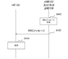
- FIG. 4 is a diagram showing an example of a flow of procedures for various settings in the RRC according to the embodiment of the present invention.
- FIG. 4 is an example of a flow in which an RRC message is sent from the base station device (eNB 102 and / or gNB 108) to the terminal device (UE 122).
- the base station apparatus creates an RRC message (step S400).
- the RRC message may be created in the base station device so that the base station device distributes broadcast information (SI: System Information) and paging information. Further, the RRC message may be created in the base station device so that the base station device can perform processing on a specific terminal device.
- the process to be performed on a specific terminal device may include, for example, security-related settings, RRC connection resetting, handover to a different RAT, suspension of RRC connection, release of RRC connection, and the like.
- RRC connection resetting processes include, for example, wireless bearer control (establishment, modification, release, etc.), cell group control (establishment, addition, modification, release, etc.), measurement setting, handover, security key update, etc. May be included.
- the RRC message may be created in the base station device in order to respond to the RRC message transmitted from the terminal device.
- the response to the RRC message transmitted from the terminal device may include, for example, a response to an RRC setup request, a response to an RRC reconnection request, a response to an RRC restart request, and the like.
- the RRC message contains information (parameters) for various information notifications and settings. These parameters may be called fields and / or information elements, and may be described using a description method called ASN.1 (Abstract Syntax Notation One).
- the base station device then transmits the created RRC message to the terminal device (step S402).
- the terminal device performs processing when processing such as setting is required according to the received RRC message (step S404).
- the processed terminal device may send an RRC message for response to the base station device (not shown).
- the RRC message is not limited to the above example, and may be used for other purposes.
- the RRC on the master node side is used to transfer RRC messages for SCG side settings (cell group settings, wireless bearer settings, measurement settings, etc.) to and from the terminal device. good.
- SCG side settings cell group settings, wireless bearer settings, measurement settings, etc.
- the RRC message of E-UTRA transmitted and received between the eNB 102 and the UE 122 may include the RRC message of NR in the form of a container.
- the RRC message of NR transmitted and received between gNB 108 and UE 122 may include the RRC message of E-UTRA in the form of a container.
- RRC messages for settings on the SCG side may be sent and received between the master node and the secondary node.
- the RRC message for E-UTRA transmitted from eNB 102 to UE 122 may include the RRC message for NR, and the RRC for NR transmitted from gNB 108 to UE 122 may be included.
- the message may include an RRC message for E-UTRA.
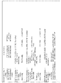
- FIG. 7 is an example of an ASN.1 description representing a field and / or an information element relating to the radio bearer configuration included in the message relating to the resetting of the RRC connection in NR in FIG.
- FIG. 8 is an example of an ASN.1 description representing a field and / or an information element related to the radio bearer setting included in the message regarding the resetting of the RRC connection in E-UTRA in FIG.
- ⁇ omitted> and ⁇ omitted> are not a part of the notation of ASN.1 and other information is omitted.
- ASN.1 does not correctly follow the ASN.1 notation method.
- the example of ASN.1 describes an example of the parameters of the RRC message in the embodiment of the present invention, and other names and other notations may be used.
- the example of ASN.1 shows only an example relating to the main information closely related to one embodiment of the present invention in order to avoid complicated explanation.
- the parameters described in ASN.1 may be referred to as information elements without distinguishing them into fields, information elements, and the like. Further, in the embodiment of the present invention, the fields, information elements, etc.
- the message regarding the resetting of the RRC connection may be an RRC resetting message in NR or an RRC connection resetting message in E-UTRA.
- the master cell group (MCG) setting and the secondary cell group (SCG) are set by the above-mentioned message regarding the resetting of the RRC connection.
- Each cell group may be composed of a special cell (SpCell) and zero or more cells (secondary cell: SCell) other than the special cell (SpCell).
- SpCell secondary cell
- SCG's SpCell is also called PCell.
- Cell inactivation does not apply to SpCell, but may apply to SCell.
- cell inactivation does not apply to PCells and may apply to PSCells.
- the cell inactivation may be a different process for SpCell and SCell.
- Cell activation and deactivation may be handled by the MAC entity that exists for each cell group.
- the SCell set in the terminal device may be activated and / or inactivated by the following (A) and / or (B).
- the MAC entity of the terminal device may perform the following processing (AD) for each SCell set in the cell group.
- Processing AD If the RRC parameter (sCellState) set in SCell at the time of SCell setting is set to activated, or if a MAC CE that activates SCell is received, the MAC entity of UE 122 processes (AD-1). I do. Otherwise, if the MAC CE that inactivates the SCell is received, or if the SCell inactivation timer expires in the active SCell, the MAC entity of UE 122 performs processing (AD-2). If the PDCCH of the active SCell notifies the uplink grant or downlink assignment, or if the PDCCH of a serving cell notifies the uplink grant or downlink assignment to the active SCell, or it is set.
- the MAC entity on UE 122 restarts the SCell inactivation timer associated with that SCell. If the SCell becomes inactive, the MAC entity of UE 122 performs processing (AD-3).
- this SCell was inactive before receiving the MAC CE that activates this SCell, or the RRC parameter (sCellState) set for that SCell when setting the SCell is set to activated. If so, the MAC entity of UE 122 performs processing (AD-1A) or processing (AD-1B). Also, the MAC entity of UE 122 starts or restarts the SCell Inactivation timer associated with that SCell (if it has already started). If the Active DL BWP is not the Dormant BWP described below, the MAC entity of the UE 122 implements some or all of (A) to (B) below.
- (A) Initializes (again) a certain suspended uplink grant of grant type 1 associated with this SCell according to the stored configuration, if any.
- (B) Trigger PHR. If the MAC CE that activates the SCell is received, the BWP indicated by the firstActiveDownlinkBWP identifier (firstActiveDownlinkBWP-Id) set in the RRC message for that SCell is set to the Dormant BWP. If not, the MAC entity of UE 122 performs processing (AD-1A).
- the BWP indicated by the firstActiveDownlinkBWP identifier (firstActiveDownlinkBWP-Id) set in the RRC message for that SCell is set to the Dormant BWP. If so, the MAC entity of UE 122 performs processing (AD-1B). Further, the MAC entity of the UE 122 implements a part or all of the following (A) to (B).
- the MAC entity of the UE 122 activates the SCell and applies (executes) a normal SCell operation (Operation) including a part or all of the following (A) to (E).
- SRS sounding reference signal
- B Report of channel state information
- C Monitor of PDCCH in this SCell
- D Monitor of PDCCH for this SCell
- E If PUCCH is set, PUCCH transmission in this SCell
- the MAC entity of UE 122 will stop if the BWP inactivation timer of this serving cell is running.
- the MAC entity of UE 122 deactivates this SCell. It also stops the SCell inactivation timer associated with this SCell. Inactivates all activated BWPs associated with this SCell. Flush the HARQ buffer associated with this SCell.
- the MAC entity of UE 122 implements some or all of the following (A) to (D).
- (A) Do not send SRS with this SCell.
- (B) Do not report the CSI for this SCell.
- (C) Do not transmit PUCCH, UL-SCH, and / or RACH with this SCell.
- (D) Do not monitor the PDCCH of this SCell and / or the PDCCH for this SCell.
- the MAC entity performs processing (AD) to activate and inactivate the SCell.
- the initial state of the SCell may be set by an RRC message.
- the RRC message may notify the value of the SCell Inactivation timer (information about when the timer is considered to have expired). For example, when the RRC message notifies the information indicating 40 ms as the value of the SCell inert timer, the time notified without stopping the timer after starting or restarting the timer in the above process (AD) (here). Then, when 40 ms) has elapsed, the timer is considered to have expired. Further, the SCell deactivation timer may be a timer named sCellDeactivationTimer.
- band portion (BWP) will be explained.
- BWP may be a part or all of the serving cell band.
- BWP may be referred to as carrier BWP (Carrier BWP).
- One or more BWPs may be set in the terminal device.
- a BWP may be set by the information contained in the broadcast information associated with the sync signal detected in the initial cell search.
- a BWP may have a frequency bandwidth associated with the frequency at which the initial cell search is performed.
- a certain BWP may be set by RRC signaling (for example, Dedicated RRC signaling).
- the downlink BWP (DL BWP) and the uplink BWP (UL BWP) may be set individually.
- one or more uplink BWPs may be associated with one or more downlink BWPs.
- the association between the uplink BWP and the downlink BWP may be the default association, the association by RRC signaling (for example, Dedicated RRC signaling), or the physical layer signaling (for example, downlink).
- the correspondence may be based on the downlink control information (DCI) notified by the control channel, or may be a combination thereof.
- DCI downlink control information
- BWP may be composed of a group of continuous physical radio blocks (PRB: Physical Resource Block). Further, the BWP (one or a plurality of BWP) parameters of each component carrier may be set for the terminal device in the connected state.
- the BWP parameters for each component carrier include (A) cyclic prefix type, (B) subcarrier spacing, and (C) BWP frequency position (eg, low frequency start or center frequency position of BWP) ( For the frequency position, for example, ARFCN may be used, an offset from a specific subcarrier of the serving cell may be used, and the unit of the offset may be a subcarrier unit or a resource block unit. Good.
- both ARFCN and offset may be set), (D) BWP bandwidth (eg PRB number), (E) control signal resource setting information, (F) SS block center frequency.
- Position for example, ARFCN may be used for the frequency position, an offset from a specific subcarrier of the serving cell may be used, and the unit of the offset may be a subcarrier unit, or a resource block. It may be in units, and both ARFCN and offset may be set), and may include some or all.
- the resource setting information of the control signal may be included in the BWP settings of at least a part or all of PCell and / or PSCell.
- the terminal device may transmit and receive in the active BWP (Active BWP) among one or more set BWPs.
- active BWP active BWP
- up to one uplink BWP and / or up to one downlink BWP are active at a given time.
- BWP may be set.
- the activated downlink BWP is also called Acitve DL BWP.
- the activated uplink BWP is also called Active UL BWP.
- One or more BWPs may be set in one serving cell. BWP switching in the serving cell is used to activate the inactivated BWP (also referred to as Inactive BWP) and inactivate the activated BWP.
- Inactive BWP the inactivated BWP
- BWP switching is controlled by the MAC entity itself for the initiation of PDCCH, BWP inactivity timer, RRC signaling, or random access procedure indicating downlink assignment or uplink grant.
- the Active BWP of the serving cell is indicated by RRC or PDCCH.
- dormant BWP Entering or leaving the dormant BWP is done by switching the BWP. This control is performed by PDCCH for each SCell or for each group called a dormant SCell group (Dormancy SCell Group). The configuration of the dormant SCell group is indicated by RRC signaling. Also, in the current specification, dormant BWP applies only to SCell. Note that the dormant BWP does not change a certain BWP to a dormant state, but may be interpreted as one BWP set for dormancy among one or more BWPs set for the UE. .. Further, there may be a plurality of BWPs set in the UE for dormancy.
- a BWP is a dormant BWP may be indicated by the fact that the BWP settings do not include certain parameters.
- the BWP is a dormant BWP by not including the PDCCH-Config information element, which is an information element for setting UE-specific PDCCH parameters included in the downlink BWP configuration. May be shown. Also, for example, some of the parameters included in the PDCCH-Config information element, which is an information element for setting UE-specific (Specific) PDCCH parameters included in the downlink BWP settings, are not set (not included). ) May indicate that the BWP is a dormant BWP.
- the setting of dormant BWP to PUCCH SCell that can send SpCell and PUCCH such as PCell and PSCell may not be supported.
- a UE that receives a PDCCH on the SpCell indicating that it will exit the dormant BWP outside a set period (active time) will receive a downlink BWP indicated by the first downlink BWP identifier notified in advance by RRC signaling. Activate.
- a UE that receives a PDCCH on the SpCell indicating that it will exit the dormant BWP within a set period (active time) will receive the downlink BWP indicated by the second downlink BWP identifier notified in advance by RRC signaling. Activate.
- the UE that received the PDCCH indicating that it will enter the dormant BWP activates the downlink BWP indicated by the third downlink BWP identifier (dormantDownlinkBWP-Id) notified in advance by RRC signaling.
- the above entry and exit to the dormant BWP is performed by switching the BWP, and when a new BWP is activated, the previously active BWP is inactivated. That is, when exiting the dormant BWP, the dormant BWP is inactivated, and when entering the dormant BWP, the dormant BWP is activated.
- a UE configured for intermittent reception (DRX) in the SpCell may monitor the PDCCH in the Active BWP of the SpCell to detect a DCI format (eg DCI format 2_6) outside the DRX active time. good.
- the CRC in DCI format may be scrambled with a certain RNTI (eg PS-RNTI).
- the UE with the dormant SCell group determines the Active DL BWP switch based on the bitmap information contained in the payload of DCI format 2_6.
- a bit in the bitmap is associated with one dormant SCell group and the bit is 1, and the Active DL BWP is a dormant BWP, perform a BWP switch to another preset BWP. If the Active DL BWP is not a dormant BWP, you may want to stay at that BWP. Also, when the bit is 0, Active DL A BWP switch may be performed so that the BWP becomes a dormant BWP.
- the UE does not have to monitor the PDCCH for the purpose of detecting DCI format 2_6 during the DRX active time.
- a UE for which intermittent reception (DRX) is set in SpCell may monitor PDCCH with Active BWP of SpCell in order to detect a certain DCI format (for example, DCI formats 0_1 and 1_1) in the active time of DRX.
- the CRC in DCI format may be scrambled with some RNTI (eg C-RNTI or MCS-C-RNTI).
- the UE in which the dormant SCell group is set determines the switching of Active DL BWP based on the bitmap information contained in the payload of DCI format 0_1 or DCI format 1_1.
- a bit with a bitmap is associated with one dormant SCell group and the bit is 1, and the Active DL BWP is a dormant BWP, BWP switching to another preset BWP is executed. If the Active DL BWP is not a dormant BWP, it may stay at that BWP. Further, when the bit is 0, BWP switching may be executed so that Active DL BWP becomes dormant BWP. Further, the "another preset BWP" may be a BWP different from the "another preset BWP" used in the description of DCI format 2_6.
- the UE does not have to monitor PDCCH for the purpose of detecting DCI format 0_1 and DCI format 1_1 outside the active time of DRX.
- Monitoring the PDCCH indicating exiting the dormant BWP means monitoring the PDCCH for the purpose of detecting DCI format 2_6 outside the DRX active time, and in the DRX active time, DCI format 0_1 and DCI format 1_1. It may be to monitor the PDCCH for the purpose of detecting.
- the MAC entity is part of (A) to (H) below if the BWP is activated (is an Active BWP) and the BWP is not a dormant BWP. Or do it all.
- A Send UL-SCH with the BWP.
- B If a PRACH occasion is set, send RACH with that BWP.
- C Monitor PDCCH with the BWP.
- D If PUCCH is set, PUCCH is transmitted by that BWP.
- E Report the CSI in the BWP.
- SRS If SRS is set, send SRS with that BWP.
- G Receive DL-SCH at the BWP.
- H Initialize the grant type 1 confidated upstream link grant set and suspended by the BWP.
- the MAC entity is one of (A) to (G) below if the BWP is activated (is an Active BWP) and the BWP is a dormant BWP. Do part or all.
- A If the BWP inactivation timer of this BWP serving cell is running, stop it.
- B Do not monitor the PDCCH of the BWP.
- C Do not monitor the PDCCH for that BWP.
- D The BWP does not receive DL-SCH.
- F Do not send SRS with that BWP.
- G Do not send UL-SCH on that BWP.
- H Do not send RACH on that BWP.
- the MAC entity if the BWP is inactivated, does some or all of (A) through (I) below.
- G The BWP does not receive DL-SCH.
- H Clear the Grant Type 2 Configure Uplink Grant set in the BWP.
- the MAC entity When initiating a random access procedure in a serving cell, the MAC entity performs some or all of the following (A) to (E) on the selected carrier of this serving cell.
- (A) If the resource (occasion) for transmitting PRACH is not set for Active UL BWP, (A1) Switch Active UL BWP to BWP indicated by the RRC parameter (initialUplinkBWP), and (A2). If the serving cell is a SpCell, switch the Active UL BWP to the BWP indicated by the RRC parameter initialDownlinkBWP.
- the serving cell is SpCell, and Active DL BWP and Active UL BWP have the same identifier (bwp-Id). If not, switch Active DL BWP to BWP with the same identifier as Active UL BWP.
- C If the BWP inactivation timer associated with the Active DL BWP of this serving cell is running, this timer is stopped.
- D If the serving cell is SCell, stop this timer if the BWP inactivity timer associated with the Active DL BWP of SpCell is running.
- E Execute a random access procedure on the Active DL BWP of SpCell and the Active UL BWP of this serving cell.
- the MAC entity performs the following processing (A) for each of the activated Serving Cells in which the BWP inactivation timer is set.
- the BWP inactivity timer may also be a timer named bwp-InactivityTimer.
- the next process (A) is performed.
- defaultDownlinkBWP-Id default downlink BWP identifier
- the switched Active DL BWP is not the BWP indicated by the identifier (dormantDownlinkBWP-Id)
- the switched Active DL BWP is dormantDownlinkBWP- If it is not the BWP indicated by Id, start or restart the BWP inactivity timer associated with the Active DL BWP.
- the beam failure recovery procedure may be set by RRC for each serving cell. Beam failure is detected by counting the beam failure instance notifications notified to the MAC entity from the lower layer (PHY layer).
- the MAC entity may perform some or all of the following processes (A), (B), and (C) in each serving cell for beam failure detection.
- (A) If a beam failure instance notification is received from a lower layer, the timer (beamFailureDetectionTimer) is started or restarted, and the counter (BFI-COUNTER) is incremented by 1. If the value of BFI_COUNTER is equal to or greater than the set threshold value (beamFailureInstanceMaxCount), the following process (A-1) is performed.
- A-1) If the serving cell is an SCell, trigger beam failure recovery (BFR) for this serving cell, otherwise the SpCell initiates a random access procedure.
- BFR beam failure recovery
- B) If the beamFailureDetectionTimer for this serving cell has expired, or if the beamFailureDetectionTimer, beamFailureInstanceMaxCount, and / or reference signal settings for beam failure detection have been changed by the higher layer, set BFI_COUNTER to 0.
- C If the serving cell is SpCell and the random access procedure is successfully completed, set BFI_COUNTER to 0, stop the timer (beamFailureRecoveryTimer), and consider that the beam failure recovery procedure has been successfully completed.
- the serving cell is an SCell, it is addressed to the C-RNTI indicating a new uplink grant to send information for the SCell's beam failure recovery (eg, the information contained in the SCell BFR MAC CE).
- the SCell's beam failure recovery eg, the information contained in the SCell BFR MAC CE.
- the MAC entity performs the process (A) below.
- the UL-SCH resource can include the BFR MAC CE of the SCell and its subheader in consideration of the priority of the logical channel, include the BFR MAC CE of the SCell and its subheader. Otherwise, if the UL-SCH resource can include the SCell's truncated BFR MAC CE and its subheaders, taking into account the logical channel priority, then the SCell's truncated BFR MAC CE and its subheaders. Include subheaders. Otherwise, it triggers a scheduling request for SCell beam failure recovery.
- SCell dormancy is performed by activating dormant BWP in this SCell. Further, even when the SCell is in a dormant state, CSI measurement, automatic gain control (AGC), and beam control (beam management) including beam failure recovery may be performed in this SCell.
- AGC automatic gain control
- beam control beam management
- the dormant state of SCG may be included in the RRC_CONNECTED state.
- the state in which the SCG is dormant means that the terminal device is a part of the following (A) to (I) in the SpCell (PSCell) of the SCG. It may be in a state where everything is carried out.
- A Do not send SRS with this SpCell.
- B Measure the CSI for this SpCell.
- C Do not report the CSI for this SpCell.
- D This SpCell does not transmit PUCCH, UL-SCH, and / or RACH.
- E Do not monitor the PDCCH of this SpCell and / or the PDCCH for this SpCell.
- the terminal device may carry out a part or all of the above (A) to (I) and the following (J) to (L).
- (J) Let the BWP set as the dormant BWP in this SpCell be the activated BWP (Active BWP).
- (K) Monitor only the PDCCH indicating exiting the dormant BWP in the activated dormant BWP of this SpCell.
- (L) C-RNTI is not monitored by PDCCH in the activated dormant BWP of this SpCell.
- the terminal device may determine and / or execute SCG dormancy based on some or all of (A) to (K) below.
- the following messages (A) to (F) and control elements may be notified to the terminal device from a cell group other than the SCG.
- Dormant of SCG may be referred to as entry into dormant SCG (Dormant SCG). Further, the dormancy of SCG may mean that the dormant BWP of SpCell of the cell group is activated.
- A Reception of RRC message instructing SCG dormancy
- B Reception of MAC control element instructing SCG dormancy
- C Reception of RRC message instructing SpCell dormancy
- D MAC instructing SpCell dormancy Receiving control elements
- E Receiving other RRC messages
- G Expiration of timer for SCG dormancy
- H Expiration of timer for dormancy of PSCell
- I Includes MAC SDU Random access procedure started due to a scheduling request triggered to send a MAC PDU
- J Random access procedure started
- K Random access caused by a scheduling request (in other words, started by the MAC entity itself) Start the procedure
- the terminal device may determine and / or execute a resume from the dormant state of the SCG based on a part or all of the following (A) to (K).
- the following messages (A) to (F) and control elements may be notified to the terminal device from a cell group other than the SCG.
- Returning the SCG from the dormant state (activating the SCG) may be referred to as leaving the dormant SCG (Leaving). Further, the return from the dormant state of SCG may be a BWP switch from the dormant BWP to another (not dormant BWP) BWP in the SpCell of the cell group.
- the terminal device that executes the dormancy of the SCG may execute a part or all of the following processes (A) to (F) in the SCG.
- A) Inactivate all SCells.
- B) All of the SCell Inactivation timers associated with the active SCell are considered to have expired.
- C) All of the SCell Inactivation timers associated with the dormant SCell are considered to have expired.
- D) Do not start or restart the SCell Inactivation Timer associated with all SCells.
- E Ignore the MAC CE that activates the S Cell.
- the process (AD-1) is performed when the MAC CE that activates the S Cell is received and the SCG is not instructed to dormant (or the SCG is not in the dormant state). .. (F)
- the process (AD-2) is executed.
- the process (AD-2) is performed.
- the terminal device that executes the return from the dormant state of the SCG may execute a part or all of the following processes (A) to (C) in the SCG.
- A) Processing (AD-1) is executed in order to activate all SCells.
- C When the SCG returns from dormancy is executed based on the RRC message, if the RRC message contains parameters related to random access to some or all SCells, the target is based on the notified parameters. Start the random access procedure in SCell.
- FIG. 9 is a diagram showing an example of the embodiment.
- the UE 122 receives a message (RRC message) notifying the eNB 102 or the gNB 108 that the SCG is in the dormant state (inactive state) (step S900). Based on the above notification, the UE 122 controls cells other than the SCG SpCell (second cell) (that is, SCell) so as to be in an inactive state (step S902).
- RRC message notifying the eNB 102 or the gNB 108 that the SCG is in the dormant state (inactive state)
- the UE 122 controls cells other than the SCG SpCell (second cell) (that is, SCell) so as to be in an inactive state (step S902).
- the transmission unit 504 of the UE 122 does not independently transmit the MAC CE for changing the SCell state of the SCG to the inactive state, and the efficient state change can be performed. It will be possible.
- SCG dormancy is executed based on the RRC message, in the past, the initial state was set in the RRC layer and the state was changed in the MAC layer. It is possible to efficiently change the SCG status while avoiding a mismatch of instructions in the MAC layer.
- the UE may monitor PDCCH with the Active BWP of the SpCell in order to detect a certain DCI format (for example, DCI format 2_6).
- the CRC in DCI format may be scrambled with a certain RNTI (eg PS-RNTI).
- the UE in which the dormant SCell group is set determines the switching of Active DL BWP based on the bitmap information included in the payload of DCI format 2_6.
- the UE executes BWP switching to another preset BWP.
- the Active DL BWP is not a dormant BWP, the UE may stay at that BWP. Further, when the bit is 0, the UE may execute BWP switching so that Active DL BWP becomes dormant BWP.
- the UE does not have to monitor PDCCH for the purpose of detecting DCI format 2_6 in the active time of DRX.
- the UE for which intermittent reception (DRX) is set in SpCell has a certain DCI format (for example, DCI format 0_1) in the active time of DRX. And 1_1) may be monitored by Active BWP of SpCell to detect PDCCH.
- the CRC in DCI format may be scrambled with some RNTI (eg C-RNTI or MCS-C-RNTI).
- the UE in which the dormant SCell group is set determines the switching of Active DL BWP based on the bitmap information contained in the payload of DCI format 0_1 or DCI format 1_1.
- the UE executes BWP switching to another preset BWP.
- the Active DL BWP is not a dormant BWP
- the UE may stay at that BWP.
- the bit is 0, the UE may execute BWP switching so that Active DL BWP becomes dormant BWP.
- the "another preset BWP" may be a BWP different from the "another preset BWP" used in the description of DCI format 2_6.
- the UE does not have to monitor PDCCH for the purpose of detecting DCI format 0_1 and DCI format 1_1 outside the active time of DRX.
- Monitoring the PDCCH indicating exiting the dormant BWP may be monitoring the PDCCH for the purpose of detecting DCI format 2_6. In doing so, the UE does not have to monitor the PDCCH for the purpose of detecting other DCI formats.
- monitoring the PDCCH indicating exiting the dormant BWP is intended to detect DCI format 2_6 outside the DRX active time.
- the PDCCH may be monitored for the purpose of detecting DCI format 0_1 and DCI format 1_1 at the active time of DRX. In doing so, the UE does not have to monitor the PDCCH for the purpose of detecting other DCI formats.
- all uplink transmissions may be stopped in the SCG.
- information about the SCG may be transmitted in another cell group (eg, MCG).
- information about the SCG may be transmitted in the SCG that has exited dormancy.
- some or all of the uplink transmissions may be permitted in the SCG.
- an example of performing uplink transmission in the SCG when the SCG is in a dormant state will be described.
- beam failure recovery when beam control (beam management) including beam failure recovery is performed in a dormant SCG SpCell will be described.
- the beam failure recovery procedure may be set by RRC for each serving cell.
- the dormant SCG may set and / or perform the beam failure recovery procedure only on the SpCell, and the dormant SCG may set and / or perform the beam failure recovery procedure on the SpCell and some or all of the SCells. / Or may be performed.
- Beam failure is detected by counting the beam failure instance notifications notified to the MAC entity from the lower layer (PHY layer).
- the MAC entity may perform some or all of the following processes (A), (B), and (C) in each serving cell for beam failure detection.
- A If a beam failure instance notification is received from a lower layer, the timer (beamFailureDetectionTimer) is started or restarted, and the counter (BFI-COUNTER) is incremented by 1. If the value of BFI_COUNTER is equal to or greater than the set threshold value (beamFailureInstanceMaxCount), the following process (A-1) is performed. (A-1) If the serving cell is an SCell, trigger beam failure recovery (BFR) for this serving cell, otherwise the SpCell initiates a random access procedure. If SCell does not trigger beam recovery, it is not necessary to trigger beam failure recovery for SCell here. That is, the process of starting the random access procedure in SpCell may be performed only when the serving cell is SpCell.
- BFR beam failure recovery
- the MAC entity should request a scheduling request for SCell beam failure recovery, if necessary, if at least one beam failure recovery (BFR) has been triggered by the beam failure recovery procedure and it has not been cancelled. Trigger.
- BFR beam failure recovery
- the SCG's MAC entity initiates a random access procedure in SpCell if a valid PUCCH resource for the Pending scheduling request has not been set.
- the MAC PDU may not include the MAC SDU.
- a random access procedure in SpCell is started in the dormant SCG by triggering a scheduling request to send a MAC PDU containing data (MAC SDU) from higher layers such as user data and RRC messages. May be done.
- the PHR procedure is used to provide the serving gNB with some or all of the information in (A) to (C) below.
- A) Difference between the maximum transmission power of the nominal UE and the estimated transmission power of the UL-SCH for each activated serving cell (B) The maximum transmission power of the nominal UE and others Difference from UL-SCH and / or PUCCH transmit power estimates on the MAC entity's SpCell (C) Maximum transmit power of the nominal UE and SRS transmit power per activated serving cell Difference from the estimated value
- the information (A), (B), and (C) may be referred to as a type 1 power headroom, a type 2 power headroom, and a type 3 power headroom, respectively. Further, the information including a part or all of the above (A) to (C) may be referred to as a power headroom.
- a MAC CE that includes only one set of power headroom type, target cell, and maximum transmission power information in that cell may be referred to as Single Entry PHR MAC CE.
- a MAC CE including a plurality of power headroom types, a target cell, and a plurality of sets of information on the maximum transmission power in the cell may be referred to as Multiple Entry PHR MAC CE.
- the uplink is set in a MAC entity, and the BWP indicated by the first downlink BWP identifier (firstActiveDownlinkBWP-Id) set in the RRC message is set to Dormant BWP.
- the MAC entity of the UE may trigger a PHR if an SCell that has not been activated is activated. Also, the UE MAC entity may trigger a PHR when a new PSCell is added or modified.
- the activated BWP of an SCell that has an uplink set in a MAC entity is changed from a dormant (DL) BWP to a non-hibernate DL BWP, the UE MAC entity will You may trigger PHR.
- the above BWP changes may be expressed as BWP switching.
- the UE MAC entity may perform some or all of the following (A), (B): .. (A) If this uplink resource is the first one since the last MAC reset, it starts a timer (phr-PeriodicTimer). (B) It is a PHR procedure that if the UE MAC entity triggers at least one PHR and this trigger is never canceled, and it is sent by the UE MAC entity. If the MAC CE for PHR set to can be accommodated within the uplink resources allocated in addition to this MAC CE subheader, taking into account the priority of the logical channel: Part or all of (B-1) to (B-5) of (B-1) is processed.
- (B-1) If the MAC CE to be accommodated is a Multiple Entry PHR MAC CE, a part or all of the following (C-1) to (C-3) is processed.
- (C-1) NR for each activated serving cell associated with any MAC entity of the same UE and having an uplink set, for which the activated DL BWP is not a dormant (DL) BWP. Gets the Type 1 or Type 3 power headroom value for the uplink carrier associated with the serving cell and E-UTRA serving cell, and if the MAC entity associated with the serving cell is for transmission on this serving cell.
- Has uplink resources assigned to, or has another MAC entity configured with the same UE has uplink resources allocated for transmission on this serving cell, and is actually transmitted on this serving cell.
- the value of this maximum transmit power is obtained from the physical layer.
- C-2 If the UE may report a Type 2 power headroom for SpCell of another MAC entity of the same UE, that type if this MAC entity is an E-UTRA MAC entity. 2 If it is decided in the upper layer to get the value of the power headroom and calculate the maximum transmission power based on the power used for the actual transmission of this MAC entity in SpCell, the physical layer. Get the value of this maximum transmit power from.
- C-3) Multiple Entry PHR MAC CE is generated and transmitted based on the value reported from the physical layer after considering the priority of the logical channel.
- B-2 If the contained MAC CE is a Single Entry PHR MAC CE, the maximum transmission associated with the Type 1 power headroom value for the uplink carrier associated with the PCell. The power value is obtained from the physical layer, the priority of the logical channel is taken into consideration, and the Single Entry PHR MAC CE is generated and transmitted based on these values.
- B-3) Start or restart the timer (phr-PeriodicTimer).
- B-4) Start or restart the timer (phr-ProhibitTimer).
- B-5) Cancel all triggered PHRs.
- FIG. 5 is a block diagram showing a configuration of a terminal device (UE122) according to an embodiment of the present invention. In order to avoid complicated explanation, FIG. 5 shows only the main components closely related to one embodiment of the present invention.
- the UE 122 shown in FIG. 5 has a receiving unit 500 that receives an RRC message or the like from a base station device, a processing unit 502 that performs processing according to parameters included in the received message, and a transmitting unit that transmits an RRC message or the like to the base station device. It consists of 504.
- the above-mentioned base station apparatus may be eNB 102 or gNB 108.
- the processing unit 502 may include some or all of the functions of various layers (for example, physical layer, MAC layer, RLC layer, PDCP layer, SDAP layer, RRC layer, and NAS layer).
- the processing unit 502 includes a physical layer processing unit, a MAC layer processing unit, an RLC layer processing unit, a PDCP layer processing unit, an SDAP processing unit, an RRC layer processing unit, and a part or all of the NAS layer processing unit. It's okay.
- FIG. 6 is a block diagram showing a configuration of a base station device according to an embodiment of the present invention. In order to avoid complicated explanation, FIG. 6 shows only the main components closely related to one embodiment of the present invention.
- the above-mentioned base station apparatus may be eNB 102 or gNB 108.
- the base station apparatus shown in FIG. 6 has a transmission unit 600 that transmits an RRC message or the like to the UE 122, and a processing unit that creates an RRC message including parameters and transmits the RRC message to the UE 122 so that the processing unit 502 of the UE 122 performs processing. It consists of a receiving unit 604 that receives an RRC message or the like from the 602 and the UE 122.
- the processing unit 602 may include some or all of the functions of various layers (for example, physical layer, MAC layer, RLC layer, PDCP layer, SDAP layer, RRC layer, and NAS layer).
- the processing unit 602 includes a part or all of the physical layer processing unit, the MAC layer processing unit, the RLC layer processing unit, the PDCP layer processing unit, the SDAP processing unit, the RRC layer processing unit, and the NAS layer processing unit. It's okay.
- FIG. 10 An example of processing of the terminal device in the embodiment of the present invention will be described with reference to FIG.
- the processing of the terminal device according to the embodiment of the present invention, which will be described with reference to FIG. 10, is expected to have effects such that the terminal device does not have to monitor a plurality of cell groups and the power consumption can be reduced. Will be done.
- FIG. 10 is a diagram showing an example of processing of a terminal device according to an embodiment of the present invention.
- the processing unit 502 of the UE 122 may determine that the SCG changes from the dormant state (inactive state) to the return state from the dormant state (active state) (step S1000). Further, the processing unit 502 of the UE 122 may perform an operation in the active state based on the above determination (step S1002).
- the UE 122 may perform a part or all of the following (A) to (N) in each of the SpCell and / or one or more SCells of a certain cell group in the active state.
- A Monitor PDCCH.
- B Send SRS.
- C Send PUCCH.
- D Send UL-SCH.
- E Send RACH.
- F Monitor the PDCCH addressed to C-RNTI, MCS-C-RNTI, and / or CS-RNTI indicating the uplink grant for UL-SCH transmission.
- the BWP is activated and monitors the C-RNTI, MCS-C-RNTI, and / or PDCCH addressed to the CS-RNTI indicating uplink grants in the BWP described above.
- H Measure the channel state information (CSI) for BWP.
- I Report channel state information (CSI) for BWP.
- J Automatic gain control (AGC) is performed.
- K Perform beam control (beam management) including beam failure recovery.
- RLM Radio Link Monitoring
- M Intermittent reception (DRX) is performed.
- N Do not monitor the PDCCH indicating exiting the dormant BWP (exiting the dormant BWP).
- the active state may be a state in which SCG is activated. Further, the above-mentioned active state may be a state in which the SCG is resumed from the dormant state. Further, the above-mentioned active state may be a state in which the above-mentioned SCG is not in a dormant state.
- the above-mentioned active state is the MAC including the MAC SDU. It may be in a state of transition from the inactive state when a random access procedure resulting from a scheduling request triggered to send a PDU is initiated. Further, the above-mentioned active state may be a state of transitioning from the inactive state when the RRC entity instructs to return from the dormant state.
- step S1000 when the transition from the inactive state to the active state of SCG is completed, the processing unit 502 of the UE 122 may determine the transition. Further, the processing unit 502 of the UE 122 may determine the transition while the SCG is transitioning from the inactive state to the active state.
- the UE 122 may transition the SCG from the inactive state to the active state (in other words, the SCG may be activated). Further, when the UE 122 receives the information instructing the SCG to return from the dormant state (Resume), the UE 122 may shift the SCG from the inactive state to the active state. Further, when the UE 122 receives the information instructing the SpCell to return from the dormant state, the UE 122 may shift the SCG from the inactive state to the active state. Further, when the UE 122 receives other information, the SCG may be changed from the inactive state to the active state.
- the UE 122 may also transition the SCG from the inactive state to the active state based on the timer for the dormancy of the SCG.
- the UE 122 may also transition the SCG from the inactive state to the active state based on the timer for the dormancy of the PS Cell.
- the UE 122 may also transition the SCG from the inactive state to the active state when initiating a random access procedure resulting from a scheduling request triggered to send a MAC PDU containing the MAC SDU.
- the UE 122 may also transition the SCG from the inactive state to the active state when initiating the random access procedure.
- the UE 122 may also transition the SCG from the inactive state to the active state when initiating a random access procedure resulting from a scheduling request (in other words, initiated by the MAC entity itself). Also, the MAC entity of UE 122 may obtain instructions to activate SCG, return from dormant SCG, return from dormant state of SpCell, and / or other information from the RRC entity of UE 122. ..
- FIG. 11 is a diagram showing an example of processing of a terminal device according to an embodiment of the present invention.
- the processing unit 502 of the UE 122 may determine that the SCG changes from the active state to the inactive state (step S1100). Further, the processing unit 502 of the UE 122 may operate in the inactive state based on the above determination (step S1102).
- the inactive state may be a state in which the UE 122 performs a part or all of the following (A) to (M) in the SpCell and / or one or more SCells of a certain cell group.
- A Do not monitor PDCCH.
- B Do not send SRS.
- C Do not send PUCCH.
- D Do not send UL-SCH.
- E Do not send RACH.
- F Do not monitor the PDCCH addressed to C-RNTI, MCS-C-RNTI, and / or CS-RNTI indicating the uplink grant for UL-SCH transmission.
- BWP is activated and does not monitor C-RNTI, MCS-C-RNTI, and / or PDCCH addressed to CS-RNTI indicating uplink grants in the above BWP.
- H Measure the channel state information (CSI) for BWP.
- I Do not report channel state information (CSI) for BWP.
- J Automatic gain control (AGC) is not performed.
- K Do not perform beam control (beam management) including beam failure recovery.
- L Do not perform Radio Link Monitoring (RLM).
- M Intermittent reception (DRX) is performed.
- the inactive state may be a state in which the SCG is inactivated.
- the inactive state described above may also be Entering the dormant SCG.
- the above-mentioned inactive state may be the above-mentioned dormant state of SCG.
- the inactive state may be a state in which the SCG SpCell and / or the Active BWP of one or more SCells is a dormant BWP.
- the above-mentioned inactive state may be a state in which the transition from the active state is started when the random access procedure caused by the scheduling request triggered to send the MAC PDU containing the MAC SDU is started. ..
- the above-mentioned inactive state may be a state in which the RRC entity transitions from the active state when the entry to the dormant state is instructed.
- step S1100 when the transition from the active state to the inactive state of the SCG is completed, the processing unit 502 of the UE 122 may determine the transition. Further, the processing unit 502 of the UE 122 may determine the transition while the SCG is transitioning from the active state to the inactive state.
- the UE 122 may transition the SCG from the active state to the inactive state. Further, the UE 122 may shift the SCG from the active state to the inactive state when it receives the information instructing the entry (Entering) into the dormant SCG. Further, when the UE 122 receives the information indicating the dormancy of the SpCell, the UE 122 may shift the SCG from the active state to the inactive state. Further, when the UE 122 receives other information, the SCG may be changed from the active state to the inactive state.
- the UE 122 may shift the SCG from the active state to the inactive state when the timer for the SCG dormancy expires. Further, the UE 122 may shift the SCG from the active state to the inactive state when the timer for the dormancy of the PS Cell expires. The UE 122 may also transition the SCG from the active state to the inactive state when initiating a random access procedure resulting from a scheduling request triggered to send a MAC PDU containing the MAC SDU. The UE 122 may also transition the SCG from the active state to the inactive state when initiating the random access procedure.
- the UE 122 may also transition the SCG from the active state to the inactive state when initiating a random access procedure resulting from a scheduling request (in other words, initiated by the MAC entity itself).
- the MAC entity of UE 122 may also obtain instructions to inactivate SCG, to enter dormant SCG, to dormant SpCell, and / or other information from the RRC entity of UE 122.
- FIG. 12 is a diagram showing an example of processing of a terminal device according to an embodiment of the present invention.
- the processing unit 502 of the UE 122 may trigger the PHR (step S1202) when an event including a part or all of the following (A) to (C) occurs (step S1200).
- the transmission unit 504 of the UE 122 may transmit the PHR triggered by the processing unit 502 to the base station apparatus.
- the event including a part or all of (A) to (C) may include other than (A), (B), and (C).
- the SCG changes from the inactive state to the active state.
- firstActiveDownlinkBWP-Id may be the same value as or different from the uplink BWP identifier (firstActiveUplinkBWP-Id) set in the RRC message.
- the addition of a new PSCell may be performed by RRC after the firstActiveDownlinkBWP-Id and firstActiveUplinkBWP-Id in the PSCell are set as the same value in the network. Further, the PSCell may be changed by RRC after the firstActiveDownlinkBWP-Id and the firstActiveUplinkBWP-Id in the changed PSCell are set as the same value in the network.
- step S1202 An example of the PHR trigger in step S1202 will be described. If the SCG in the UE 122 transitions from the inactive state to the active state in step S1200, the MCG and / or the MAC entity for the SCG in the UE 122 may trigger the PHR.
- the wireless bearers in the above description may be DRBs, SRBs, DRBs and SRBs, respectively.
- SCG SpCell may be paraphrased as "PS Cell”.
- the “sleeping state” in the above description may be paraphrased as the "inactive state", and the “recovered state from the dormant state” may be paraphrased as the "active state”. Further, in the above description, “activation” and “inactivation” may be paraphrased as “active state” and “inactive state”, respectively.
- A may be paraphrased as B
- B may include the meaning of paraphrasing B as A in addition to paraphrasing A as B.
- C may be D
- C C may be E
- D may be E
- F may be G
- G G may be H
- F H
- condition "A” and the condition "B” are contradictory, the condition “B” may be expressed as the “other” condition of the condition "A”. good.
- the first embodiment of the present invention is a terminal device in which a first cell group and a second cell group are set, a processing unit that triggers a power headroom report (PHR), and a processing unit.
- a transmission unit that transmits the triggered PHR to the base station device is provided, and the PHR is a terminal device triggered by the processing unit based on the activation of the second cell group.
- the second embodiment of the present invention is a communication method applied to a terminal device in which a first cell group and a second cell group are set, and a power headroom report (PHR) is obtained. Triggered, the triggered PHR is transmitted to the base station apparatus, and the PHR is a communication method triggered based on the activation of the second cell group.
- PHR power headroom report
- the third embodiment of the present invention is a base station device for setting a first cell group and a second cell group in a terminal device, and a power headroom report (PHR) is transmitted from the terminal device.
- the PHR is a base station device that comprises a receiving unit to receive and is triggered by the terminal device based on the activation of the second cell group.
- the fourth embodiment of the present invention is a communication method applied to a terminal device in which a first cell group and a second cell group are set, and a power headroom report (PHR) is obtained. Triggered, the triggered PHR is transmitted to the base station apparatus, and the PHR is a communication method triggered by the processing unit based on the activation of the second cell group.
- PHR power headroom report
- a program operating on a device controls a Central Processing Unit (CPU) or the like to operate a computer so as to realize the functions of the above-described embodiment related to one aspect of the present invention. It may be a program.
- the program or the information handled by the program is temporarily read into volatile memory such as Random Access Memory (RAM) at the time of processing, or stored in non-volatile memory such as flash memory or Hard Disk Drive (HDD), and is required.
- RAM Random Access Memory
- HDD Hard Disk Drive
- a part of the apparatus in the above-described embodiment may be realized by a computer.
- the program for realizing this control function is recorded on a recording medium that can be read by the computer, and the program recorded on this recording medium is read by the computer system and executed. May be good.
- the "computer system” as used herein is a computer system built into the device, and includes hardware such as an operating system and peripheral devices.
- the "recording medium that can be read by a computer” may be any of a semiconductor recording medium, an optical recording medium, a magnetic recording medium, and the like.
- a "recording medium that can be read by a computer” is a communication line that dynamically holds a program for a short time, like a communication line when a program is transmitted via a network such as the Internet or a communication line such as a telephone line. It may also include a program that holds a program for a certain period of time, such as a volatile memory inside a computer system that is a server or a client in that case. Further, the above program may be for realizing a part of the above-mentioned functions, and may be further realized by combining the above-mentioned functions with a program already recorded in the computer system. ..
- each functional block or feature of the device used in the above-described embodiment can be implemented or executed in an electric circuit, that is, typically an integrated circuit or a plurality of integrated circuits.
- Electrical circuits designed to perform the functions described herein can be general purpose processors, digital signal processors (DSPs), application specific integrated circuits (ASICs), field programmable gate arrays (FPGAs), or others.
- Programmable Logic Devices Discrete Gate or Transistor Logic, Discrete Hardware Components, or Combinations thereof.
- the general purpose processor may be a microprocessor or instead the processor may be a conventional processor, controller, microprocessor, or steady machine.
- the general-purpose processor or each of the above-mentioned circuits may be composed of a digital circuit or an analog circuit.
- an integrated circuit technology that replaces the current integrated circuit appears due to advances in semiconductor technology, it is also possible to use an integrated circuit based on this technology.
- the invention of the present application is not limited to the above-described embodiment.
- an example of the device has been described, but the present invention is not limited to this, and the present invention is not limited to this, and the stationary or non-movable electronic device installed indoors and outdoors, for example, an AV device, a kitchen device, and the like. It can be applied to terminal devices or communication devices such as cleaning / washing equipment, air conditioning equipment, office equipment, vending machines, and other living equipment.
- One aspect of the present invention is used in, for example, a communication system, a communication device (for example, a mobile phone device, a base station device, a wireless LAN device, or a sensor device), an integrated circuit (for example, a communication chip), a program, or the like. be able to.
- a communication device for example, a mobile phone device, a base station device, a wireless LAN device, or a sensor device
- an integrated circuit for example, a communication chip
- a program or the like.
- E-UTRA 102 eNB 104 EPC 106 NR 108 gNB 110 5GC 112, 114, 116, 118, 120, 124 Interface 122 UE 200, 300 PHY 202, 302 MAC 204, 304 RLC 206, 306 PDCP 208, 308 RRC 310 SDAP 210, 312 NAS 500,604 Receiver 502,602 Processing 504,600 Transmitter
Landscapes
- Engineering & Computer Science (AREA)
- Signal Processing (AREA)
- Computer Networks & Wireless Communication (AREA)
- Mobile Radio Communication Systems (AREA)
Abstract
Description
本願は、2020年9月30日に日本に出願された特願2020-165020号について優先権を主張し、その内容をここに援用する。
PDCCH(物理下りリンク制御チャネル:Physical Downlink Control CHannel)
PDSCH(物理下りリンク共用チャネル:Physical Downlink Shared CHannel)
PUCCH(物理上りリンク制御チャネル:Physical Uplink Control CHannel)
PUSCH(物理上りリンク共用チャネル:Physical Uplink Shared CHannel)
PRACH(物理ランダムアクセスチャネル:Physical Random Access CHannel)
Control PDU、SDAPコントロールPDU、SDAP制御PDU)と呼んで良い。なお端末装置のSDAPエンティティは、PDUセッションに対して一つ存在して良い。
ルグループ(Secondary Cell Group:SCG)に関連付けられている場合、SpCellはプライマリSCGセル(Primary SCG Cell:PSCell)を意味して良い。またMACエンティティがセルグループに関連付けられていない場合、SpCellはPCellを意味して良い。PCell、PSCellおよびSCellはサービングセルである。SpCellはPUCCH送信およびコンテンション基準ランダムアクセス(contention-based Random Access)をサポートして良いし、またSpCellは常に活性化されても良い。PCellはRRCアイドル状態の端末装置がRRC接続状態に遷移する際の、RRC接続確立手順に用いられるセルであって良い。またPCellは、端末装置がRRC接続の再確立を行う、RRC接続再確立手順に用いられるセルであって良い。またPCellは、ハンドオーバの際のランダムアクセス手順に用いられるセルであって良い。PSCellは、後述するセカンダリノード(Secondary Node:SN)追加の際に、ランダムアクセス手順に用いられるセルであって良い。またSpCellは、上述の用途以外の用途に用いられるセルであって良い。なお、セルグループがSpCell及び1つ以上のSCellから構成される場合、このセルグループにはキャリアアグリゲーション(carrier aggregation:CA)が設定されていると言って良い。また、CAが設定されている端末装置に対して、SpCellに対して追加の無線リソースを提供しているセルはSCellを意味して良い。
(A)SCell活性化/不活性化を示すMAC CEの受信
(B)PUCCHが設定されていないSCellごとに設定されるSCell不活性タイマー
もし、SCell設定の際にSCellに設定されているRRCパラメータ(sCellState)がactivatedに設定されている、またはSCellを活性化させるMAC CEを受信した場合、UE122のMACエンティティは処理(AD-1)を行う。そうでなく、もし、SCellを不活性化させるMAC CEを受信した、または、活性状態のSCellにおいてSCell不活性タイマーが満了したら、UE122のMACエンティティは処理(AD-2)を行う。もし、活性状態のSCellのPDCCHによって上りリンクグラントまたは下りリンク割り当てが通知されたら、または、あるサービングセルのPDCCHによって、活性状態のSCellに対する上りリンクグラントまたは下りリンク割り当てが通知されたら、または、設定された上りリンクグラントにおいてMAC PDUが送信された、または、設定された下りリンク割り当てにおいてMAC PDUが受信されたら、UE122のMACエンティティはそのSCellに関連付けられたSCell不活性タイマーを再スタートする。もし、SCellが不活性状態となったら、UE122のMACエンティティは処理(AD-3)を行う。
もし、NRにおいて、このSCellを活性化させるMAC CEを受信する前にこのSCellが不活性状態であった、またはSCell設定の際にそのSCellに設定されているRRCパラメータ(sCellState)がactivatedに設定されているならば、UE122のMACエンティティは処理(AD-1A)または処理(AD-1B)を行う。
また、UE122のMACエンティティはそのSCellに対応付けられたSCell不活性タイマーをスタート、または(すでにスタートしている場合は)再スタートする。
もし、Active DL BWPが後述の休眠BWP(Dormant BWP)でない場合、UE122のMACエンティティは下記(A)から(B)の一部または全部を実施する。
(A)もしあれば貯蓄された設定(stored configuration)に従って、このSCellに対応付けられている、グラントタイプ1のサスペンドされたあるコンフィギュアード上りリンクグラントを(再び)初期化する。
(B)PHRをトリガする。
もし、SCellを活性化させるMAC CEを受信し、そのSCellに対してRRCメッセージで設定されている第1アクティブ下りリンクBWP識別子(firstActiveDownlinkBWP-Id)で示されるBWPが休眠(Dormant)BWPに設定されていない場合、UE122のMACエンティティは処理(AD-1A)を行う。もし、SCellを活性化させるMAC CEを受信し、そのSCellに対してRRCメッセージで設定されている第1アクティブ下りリンクBWP識別子(firstActiveDownlinkBWP-Id)で示されるBWPが休眠(Dormant)BWPに設定されている場合、UE122のMACエンティティは処理(AD-1B)を行う。また、UE122のMACエンティティは下記(A)から(B)の一部または全部を実施する。
(A)RRCメッセージで設定されている第1アクティブ下りリンクBWP識別子(firstActiveDownlinkBWP-Id)で示されるBWPを活性化する
(B)RRCメッセージで設定されている第1アクティブ上りリンクBWP識別子(firstActiveUplinkBWP-Id)で示されるBWPを活性化する
UE122のMACエンティティはSCellを活性状態にして、下記(A)から(E)の一部または全部を含む通常のSCell動作(Operation)を適用(実施)する。
(A)このSCellにおけるサウンディング参照信号(SRS)の送信
(B)このSCellのためのチャネル状態情報(CSI)の報告
(C)このSCellにおけるPDCCHのモニタ
(D)このSCellに対するPDCCHのモニタ(他のサービングセルにおいてこのSCellに対するスケジュールが行われる場合)
(E)もしPUCCHが設定されていれば、このSCellにおけるPUCCH送信
UE122のMACエンティティはこのサービングセルのBWP不活性タイマーが走っているなら止める。
UE122のMACエンティティはこのSCellを不活性化する。
また、このSCellに対応付けられたSCell不活性タイマーを停止する。
このSCellに対応付けられたすべての活性化されたBWPを不活性化する。
このSCellに対応付けられたHARQのバッファをフラッシュする。
UE122のMACエンティティは下記(A)から(D)の一部または全部を実施する。
(A)このSCellでSRSを送信しない。
(B)このSCellのためのCSIを報告しない。
(C)このSCellでPUCCH,UL-SCH、および/またはRACHを送信しない。
(D)このSCellのPDCCH、および/またはこのSCellに対するPDCCHのモニタをしない。
BWPが休眠BWPになるようにBWP切り替えを実行してもよい。
(A)そのBWPでUL-SCHを送信する。
(B)もしPRACHオケージョンが設定されているなら、そのBWPでRACHを送信する。
(C)そのBWPでPDCCHをモニタする。
(D)もしPUCCHが設定されているなら、そのBWPでPUCCHを送信する。
(E)そのBWPでCSIを報告する。
(F)もしSRSが設定されているなら、そのBWPでSRSを送信する。
(G)そのBWPでDL-SCHを受信する。
(H)そのBWPで設定されてサスペンドされた、グラントタイプ1のコンフィギュアード上りリンクグラントを初期化する。
(A)このBWPのサービングセルのBWP不活性タイマーが走っているなら止める。
(B)そのBWPのPDCCHをモニタしない。
(C)そのBWPのためのPDCCHをモニタしない。
(D)そのBWPでDL-SCHを受信しない。
(F)そのBWPでSRSを送信しない。
(G)そのBWPでUL-SCHを送信しない。
(H)そのBWPでRACHを送信しない。
(I)そのBWPでPUCCHを送信しない。
(J)そのSCellに関連付けられたコンフィギュアード下りリンク割り当ておよびグラントタイプ2のコンフィギュアード上りリンクグラントをそれぞれクリアする。
(K)そのSCellに関連付けられたグラントタイプ1のコンフィギュアード上りリンクグラントをサスペンドする。
(L)もしビーム失敗に関する設定が設定されていたら、ビーム失敗(Beam Failure)を検出(Detect)し、もしビーム失敗が検出されたらビーム失敗回復(Beam Failure
Recovery)を実行する。
(A)そのBWPでUL-SCHを送信しない。
(B)そのBWPでRACHを送信しない。
(C)そのBWPでPDCCHをモニタしない。
(D)そのBWPでPUCCHを送信しない。
(E)そのBWPでCSIを報告しない。
(F)そのBWPでSRSを送信しない。
(G)そのBWPでDL-SCHを受信しない。
(H)そのBWPで設定された、グラントタイプ2のコンフィギュアード上りリンクグラントをクリアする。
(I)その不活性化されたBWP(インアクティブBWP)のグラントタイプ1のコンフィギュアード上りリンクグラントをサスペンドする。
(A)もし、PRACHを送信するリソース(オケージョン)が、Active UL BWPに対して設定されていなければ、(A1)Active UL BWPをRRCのパラメータ(initialUplinkBWP)によって示されるBWPに切り替え、(A2)もし、サービングセルがSpCellであれば、Active UL BWPをRRCのパラメータ初期下りリンクBWP(initialDownlinkBWP)によって示されるBWPに切り替える。
(B)もし、PRACHを送信するリソース(オケージョン)がActive UL BWPに対して設定されていれば、もし、サービングセルがSpCellであり、Active DL BWPとActive UL BWPとが同じ識別子(bwp-Id)を持たなければ、Active DL BWPをActive UL BWPの識別子と同じ識別子のBWPに切り替える。
(C)もしこのサービングセルのActive DL BWPに対応付けられたBWP不活性タイマーが走っていたらこのタイマーを止める。
(D)もしサービングセルがSCellなら、もしSpCellのActive DL BWPに対応付けられたBWP不活性タイマーが走っていたらこのタイマーを止める。
(E)SpCellのActive DL BWPとこのサービングセルのActive UL BWP上でランダムアクセスプロシージャを実行する。
(A)もしデフォルト下りリンクBWPの識別子(defaultDownlinkBWP-Id)が設定されており、Active DL BWPが識別子(dormantDownlinkBWP-Id)で示されるBWPでない、または、もしデフォルト下りリンクBWPの識別子(defaultDownlinkBWP-Id)が設定されておらず、Active DL BWPがinitialDownlinkBWPでなく、Active DL BWPが識別子(dormantDownlinkBWP-Id)で示されるBWPでないなら、MACエンティティは次の(B)および(D)の処理をおこなう。
(B)もし、Active DL BWPで、下りリンク割り当て(Assignment)または上りリンクグラントを示す、C-RNTIまたはCS-RNTIにアドレスされたPDCCHを受信した、または、もし、Active DL BWPのための、下りリンク割り当てまたは上りリンクグラントを示す、C-RNTIまたはCS-RNTIにアドレスされたPDCCHを受信した、または、もし、コンフィギュアード上りリンクグラントでMAC PDUが送信された、またはコンフィギュアード下りリンク割り当てでMAC PDUが受信されたなら、MACエンティティは次の(C)の処理をおこなう。
(C)もし、このサービングセルに関連付けられたランダムアクセス手順が実行中でない、または、このサービングセルに関連付けられた実行中のランダムアクセス手順が、C-RNTIにアドレスされたPDCCHの受信によって成功裏に完了(Successfully completed)したら、Active DL BWPに関連付けられたBWP不活性タイマーをスタートまたは再スタートする。
(D)もし、Active DL BWPに関連付けられたBWP不活性タイマーが満了(Expire)したら、MACエンティティは次の(E)の処理をおこなう。
(E)もし、defaultDownlinkBWP-Idが設定されていたら、このdefaultDownlinkBWP-Idで示されるBWPにBWP切り替えをおこない、そうでないなら、initialDownlinkBWPにBWP切り替えをおこなう。
(A)もしデフォルト下りリンクBWPの識別子(defaultDownlinkBWP-Id)が設定されており、切り替えたActive DL BWPが識別子(dormantDownlinkBWP-Id)で示されるBWPでない、かつ、もし切り替えたActive DL BWPがdormantDownlinkBWP-Idで示されるBWPでないなら、Active DL BWPに関連付けられたBWP不活性タイマーをスタートまたは再スタートする。
(A)もし、下位レイヤからビーム失敗インスタンス通知を受信したら、タイマー(beamFailureDetectionTimer)をスタートまたは再スタートし、カウンター(BFI-COUNTER)を1加算する。もしBFI_COUNTERの値が設定された閾値(beamFailureInstanceMaxCount)以上であれば、下記の(A-1)の処理をおこなう。
(A-1)もし、サービングセルがSCellなら、このサービングセルに対するビーム失敗回復(BFR)をトリガし、そうでなければ、SpCellでランダムアクセス手順を開始する。
(B)もし、このサービングセルに対する、beamFailureDetectionTimerが満了した、または、もし、beamFailureDetectionTimer、beamFailureInstanceMaxCount、および/またはビーム失敗検出のための参照信号の設定が上位レイヤによって変更されたら、BFI_COUNTERを0に設定する。
(C)もし、サービングセルがSpCellであり、ランダムアクセス手順が成功裏に完了したら、BFI_COUNTERを0に設定し、タイマー(beamFailureRecoveryTimer)を停止し、ビーム失敗回復手順が成功裏に完了したとみなす。そうでなく、もし、サービングセルがSCellで、SCellのビーム失敗回復のための情報(例えばSCell BFR MAC CEに含まれる情報)を送信するための、新しい上りリンクグラントを示すC-RNTIにアドレスされたPDCCHを受信したら、または、SCellが不活性状態であれば、BFI_COUNTERを0に設定し、ビーム失敗回復手順が成功裏に完了したとみなし、このサービングセルに対してトリガされたすべてのビーム失敗回復(BFR)をキャンセルする。
(A)もし、UL-SCHリソースが論理チャネルの優先度を考慮したうえでSCellのBFR MAC CEとそのサブヘッダを含めることができるのであれば、SCellのBFR MAC CEとそのサブヘッダを含める。そうでなければ、もし、UL-SCHリソースが論理チャネルの優先度を考慮したうえでSCellのトランケートしたBFR MAC CEとそのサブヘッダを含めることができるのであれば、SCellのトランケートしたBFR MAC CEとそのサブヘッダを含める。そうでなければ、SCellビーム失敗回復のためのスケジューリングリクエストをトリガする。
(A)このSpCellでSRSを送信しない。
(B)このSpCellのためのCSIを測定する。
(C)このSpCellのためのCSIを報告しない。
(D)このSpCellでPUCCH、UL-SCH、および/またはRACHを送信しない。
(E)このSpCellのPDCCH、および/またはこのSpCellに対するPDCCHをモニタしない。
(F)このSpCellで間欠受信(DRX)を行う。
(G)このSpCellでのUL-SCH送信のための上りリンクグラントを示すC-RNTI、MCS-C-RNTI、および/またはCS-RNTIにアドレスされた、このSpCellのPDCCH、および/またはこのSpCellに対するPDCCHをモニタしない。
(H)このSpCellでBWPが活性化されており、上述のBWPにおいて上りリンクグラントを示すC-RNTI、MCS-C-RNTI、および/またはCS-RNTIにアドレスされた、このSpCellのPDCCH、および/またはこのSpCellに対するPDCCHをモニタしない。
(I)このSpCellで自動増幅制御(Automatic Gain Control:AGC)、ビーム失敗回復を含むビーム制御(ビームマネジメント)、および/または無線リンクモニタリング(Radio Link Monitoring:RLM)を行わない。
(J)このSpCellで休眠BWPに設定されたBWPを活性化されたBWP(Active BWP)とする。
(K)このSpCellの活性化された休眠BWPにおいて休眠BWPを抜けることを示すPDCCHのみモニタする。
(L)このSpCellの活性化された休眠BWPにおいてC-RNTIをPDCCHでモニタしない。
(A)SCGの休眠を指示するRRCメッセージの受信
(B)SCGの休眠を指示するMAC制御要素の受信
(C)SpCellの休眠を指示するRRCメッセージの受信
(D)SpCellの休眠を指示するMAC制御要素の受信
(E)その他のRRCメッセージの受信
(F)その他のMAC制御要素の受信
(G)SCGの休眠に関するタイマーの満了
(H)PSCellの休眠に関するタイマーの満了
(I)MAC SDUが含まれるMAC PDUを送信するためにトリガされたスケジューリングリクエストに起因するランダムアクセス手順の開始
(J)ランダムアクセス手順の開始
(K)スケジューリングリクエストに起因する(言い換えると、MACエンティティ自身が開始した)ランダムアクセス手順の開始
(A)SCGの休眠状態からの復帰を指示するRRCメッセージの受信
(B)SCGの休眠状態からの復帰を指示するMAC制御要素の受信
(C)SpCellの休眠状態からの復帰を指示するRRCメッセージの受信
(D)SpCellの休眠状態からの復帰を指示するMAC制御要素の受信
(E)その他のRRCメッセージの受信
(F)その他のMAC制御要素の受信
(G)SCGの休眠に関するタイマー
(H)PSCellの休眠に関するタイマー
(I)MAC SDUが含まれるMAC PDUを送信するためにトリガされたスケジューリングリクエストに起因するランダムアクセス手順の開始
(J)ランダムアクセス手順の開始
(K)スケジューリングリクエストに起因する(言い換えると、MACエンティティ自身が開始した)ランダムアクセス手順の開始
(A)すべてのSCellを不活性状態とする。
(B)活性状態のSCellに関連付けられたSCell不活性タイマーのすべてが満了したとみなす。
(C)休眠状態のSCellに関連付けられたSCell不活性タイマーのすべてが満了したとみなす。
(D)すべてのSCellに関連付けられたSCell不活性タイマーをスタートまたは再スタートしない。
(E)SCellを活性化させるMAC CEを無視する。例えば、前記処理(AD)において、SCellを活性化させるMAC CEを受信して、かつ、SCGの休眠を指示されてない(またはSCGの休眠状態でない)場合に、処理(AD-1)を行う。
(F)前記処理(AD-2)を実行する。例えば、前記処理(AD)において、SCGの休眠を指示された(またはSCGの休眠状態となった)場合に、処理(AD-2)を行う。
(A)すべてのSCellを活性状態とするために、処理(AD-1)を実行する。
(B)すべてのSCellを不活性状態のままとする。ただし、休眠状態ではないので、
例えば、前記処理(AD)において、SCellを活性化させるMAC CEを受信した場合、SCGの休眠を指示されてない(またはSCGの休眠状態でない)ので、処理(AD-1)を行うようにしてもよい。
(C)SCGの休眠状態からの復帰をRRCメッセージに基づいて実行する場合、このRRCメッセージに、一部または全部のSCellに対するランダムアクセスに関するパラメータが含まれるなら、通知されたパラメータに基づき、対象のSCellにおいてランダムアクセス手順を開始する。
(A)もし、下位レイヤからビーム失敗インスタンス通知を受信したら、タイマー(beamFailureDetectionTimer)をスタートまたは再スタートし、カウンター(BFI-COUNTER)を1加算する。もしBFI_COUNTERの値が設定された閾値(beamFailureInstanceMaxCount)以上であれば、下記の(A-1)の処理をおこなう。
(A-1)もし、サービングセルがSCellなら、このサービングセルに対するビーム失敗回復(BFR)をトリガし、そうでなければ、SpCellでランダムアクセス手順を開始する。なお、SCellでビーム回復をトリガしない場合は、ここでSCellに対するビーム失敗回復をトリガしなくてもよい。すなわち、サービングセルがSpCellである場合にのみ、SpCellでランダムアクセス手順を開始する処理をおこなってよい。
(B)もし、このサービングセルに対する、beamFailureDetectionTimerが満了した、または、もし、beamFailureDetectionTimer、beamFailureInstanceMaxCount、および/またはビーム失敗検出のための参照信号の設定が上位レイヤによって変更されたら、BFI_COUNTERを0に設定する。
(C)もし、サービングセルがSpCellであり、ランダムアクセス手順が成功裏に完了したら、BFI_COUNTERを0に設定し、タイマー(beamFailureRecoveryTimer)を停止し、ビーム失敗回復手順が成功裏に完了したとみなす。そうでなく、もし、サービングセルがSCellで、SCellのビーム失敗回復のための情報(例えばSCell BFR MAC CEに含まれる情報)を送信するための、新しい上りリンクグラントを示すC-RNTIにアドレスされたPDCCHを受信したら、または、SCellが不活性状態であれば、BFI_COUNTERを0に設定し、ビーム失敗回復手順が成功裏に完了したとみなし、このサービングセルに対してトリガされたすべてのビーム失敗回復(BFR)をキャンセルする。
(A)名目上の(nominal)UEの最大送信電力と活性化されたサービングセル毎のUL-SCHの送信電力の推定値との差
(B)名目上の(nominal)UEの最大送信電力と他のMACエンティティのSpCell上のUL-SCHおよび/またはPUCCHの送信電力の推定値との差
(C)名目上の(nominal)UEの最大送信電力と活性化されたサービングセル毎のSRSの送信電力の推定値との差
(A)もしこの上りリンクのリソースが、最後にMACがリセットされてから最初のものであれば、タイマー(phr-PeriodicTimer)を開始する。
(B)もしUEのMACエンティティが最低でも一つのPHRをトリガし、このトリガがキャンセルされるということはないということがPHRのプロシージャとして決められており、またUEのMACエンティティによって送信されるために設定されたPHRのためのMAC CEが、論理チャネルの優先度を考慮したうえでこのMAC CEのサブヘッダに加えて割り当てられた上りリンクのリソース内に収容されることができるのであれば、下記の(B-1)から(B-5)の一部または全部の処理をおこなう。
(B-1)もし収容されるMAC CEがMultiple Entry PHR MAC CEであるならば、下記の(C-1)から(C-3)の一部または全部の処理をおこなう。
(C-1)同一UEの任意のMACエンティティに関連付けられた、上りリンクが設定されている活性化された各サービングセルのうち、活性化されたDL BWPが休眠(DL)BWPでないものに関して、NRサービングセルおよびE-UTRAサービングセルに対して対応付けられた上りリンクキャリアのためのタイプ1またはタイプ3パワーヘッドルームの値を取得し、もしサービングセルを関連付けているMACエンティティがこのサービングセル上での送信のために割り当てられた上りリンクのリソースを持つ、または同一UEの別のMACエンティティが設定されていて、このサービングセル上での送信のために割り当てられた上りリンクのリソースを持ち、このサービングセルでの実送信のために使われる電力を基に最大送信電力を計算することが上位レイヤで決められているのであれば、物理レイヤからこの最大送信電力の値を取得する。
(C-2)もし同一UEの別のMACエンティティのSpCellのためのタイプ2パワーヘッドルームをUEがレポートしてもよいのであれば、このMACエンティティがE-UTRAのMACエンティティであればそのタイプ2パワーヘッドルームの値を取得し、さらにこのMACエンティティのSpCellでの実送信のために使われる電力を基に最大送信電力を計算することが上位レイヤで決められているのであれば、物理レイヤからこの最大送信電力の値を取得する。
(C-3)論理チャネルの優先度を考慮したうえで物理レイヤからレポートされた値を基にMultiple Entry PHR MAC CEを生成し送信する。
(B-2)もし収容されるMAC CEがSingle Entry PHR MAC CEであるならば、PCellに対して対応付けられた上りリンクキャリアのためのタイプ1パワーヘッドルームの値と対応付けられた最大送信電力の値を物理レイヤから取得し、論理チャネルの優先度を考慮したうえでこれらの値を基にSingle Entry PHR MAC CEを生成し送信する。
(B-3)タイマー(phr-PeriodicTimer)を開始(Start)あるいは再開始(Restart)する。
(B-4)タイマー(phr-ProhibitTimer)を開始(Start)あるいは再開始(Restart)する。
(B-5)トリガされたすべてのPHRをキャンセルする。
(A)PDCCHをモニタする。
(B)SRSを送信する。
(C)PUCCHを送信する。
(D)UL-SCHを送信する。
(E)RACHを送信する。
(F)UL-SCH送信のための上りリンクグラントを示すC-RNTI、MCS-C-RNTI、および/またはCS-RNTIにアドレスされたPDCCHをモニタする。
(G)BWPが活性化されており、上述のBWPにおいて上りリンクグラントを示すC-RNTI、MCS-C-RNTI、および/またはCS-RNTIにアドレスされたPDCCHをモニタする。
(H)BWPに対するチャネル状態情報(CSI)を測定する。
(I)BWPに対するチャネル状態情報(CSI)を報告する。
(J)自動増幅制御(Automatic Gain Control:AGC)を行う。
(K)ビーム失敗回復を含むビーム制御(ビームマネジメント)を行う。
(L)無線リンクモニタリング(Radio Link Monitoring:RLM)を行う。
(M)間欠受信(DRX)を行う。
(N)休眠BWPを抜ける(休眠BWPから退出する)ことを示すPDCCHをモニタしない。
PDUを送信するためにトリガされたスケジューリングリクエストに起因するランダムアクセス手順が開始される場合に、不活性状態から遷移する状態であってもよい。また、上述の活性状態は、RRCエンティティから休眠状態からの復帰が指示された場合に、不活性状態から遷移する状態であってもよい。
(A)PDCCHをモニタしない。
(B)SRSを送信しない。
(C)PUCCHを送信しない。
(D)UL-SCHを送信しない。
(E)RACHを送信しない。
(F)UL-SCH送信のための上りリンクグラントを示すC-RNTI、MCS-C-RNTI、および/またはCS-RNTIにアドレスされたPDCCHをモニタしない。
(G)BWPが活性化されており、上述のBWPにおいて上りリンクグラントを示すC-RNTI、MCS-C-RNTI、および/またはCS-RNTIにアドレスされたPDCCHをモニタしない。
(H)BWPに対するチャネル状態情報(CSI)を測定する。
(I)BWPに対するチャネル状態情報(CSI)を報告しない。
(J)自動増幅制御(Automatic Gain Control:AGC)を行わない。
(K)ビーム失敗回復を含むビーム制御(ビームマネジメント)を行わない。
(L)無線リンクモニタリング(Radio Link Monitoring:RLM)を行わない。
(M)間欠受信(DRX)を行う。
(A)SCGが不活性状態から活性状態となる。
(B)いずれかのMACエンティティのSCellであって、上りリンクが設定されていて、RRCメッセージで設定されている第1下りリンクBWP識別子(firstActiveDownlinkBWP-Id)で示されるBWPが休眠(Dormant)BWPに設定されていないSCellの活性化。
(C)PSCellの追加(PSCellが新たに追加または変更される)。
102 eNB
104 EPC
106 NR
108 gNB
110 5GC
112、114、116,118、120、124 インタフェース
122 UE
200、300 PHY
202、302 MAC
204、304 RLC
206、306 PDCP
208、308 RRC
310 SDAP
210、312 NAS
500,604 受信部
502、602 処理部
504、600 送信部
Claims (3)
- 第1のセルグループと第2のセルグループとが設定された端末装置であって、
パワーヘッドルームレポート(PHR)をトリガする処理部と、
トリガされた前記PHRを基地局装置に送信する送信部とを備え、
前記PHRは、前記第2のセルグループが活性化されることに基づき前記処理部によってトリガされる
端末装置。 - 第1のセルグループと第2のセルグループとが設定された端末装置に適用される通信方法であって、
パワーヘッドルームレポート(PHR)をトリガし、
トリガされた前記PHRを基地局装置に送信し、
前記PHRは、前記第2のセルグループが活性化されることに基づきトリガされる
通信方法。 - 第1のセルグループと第2のセルグループとを端末装置に設定する基地局装置であって、パワーヘッドルームレポート(PHR)を端末装置から受信する受信部を備え、
前記PHRは、前記第2のセルグループが活性化されることに基づき前記端末装置によってトリガされる
基地局装置。
Priority Applications (3)
| Application Number | Priority Date | Filing Date | Title |
|---|---|---|---|
| CN202180063595.3A CN116158118A (zh) | 2020-09-30 | 2021-09-27 | 终端装置、通信方法以及基站装置 |
| EP21875536.1A EP4224914A4 (en) | 2020-09-30 | 2021-09-27 | TERMINAL DEVICE, COMMUNICATION METHOD AND BASE STATION DEVICE |
| US18/028,198 US20230379842A1 (en) | 2020-09-30 | 2021-09-27 | Terminal apparatus, communication method, and base station apparatus |
Applications Claiming Priority (2)
| Application Number | Priority Date | Filing Date | Title |
|---|---|---|---|
| JP2020165020A JP2023165045A (ja) | 2020-09-30 | 2020-09-30 | 端末装置、基地局装置および、方法 |
| JP2020-165020 | 2020-09-30 |
Publications (1)
| Publication Number | Publication Date |
|---|---|
| WO2022071234A1 true WO2022071234A1 (ja) | 2022-04-07 |
Family
ID=80951654
Family Applications (1)
| Application Number | Title | Priority Date | Filing Date |
|---|---|---|---|
| PCT/JP2021/035419 Ceased WO2022071234A1 (ja) | 2020-09-30 | 2021-09-27 | 端末装置、通信方法、および基地局装置 |
Country Status (5)
| Country | Link |
|---|---|
| US (1) | US20230379842A1 (ja) |
| EP (1) | EP4224914A4 (ja) |
| JP (1) | JP2023165045A (ja) |
| CN (1) | CN116158118A (ja) |
| WO (1) | WO2022071234A1 (ja) |
Cited By (2)
| Publication number | Priority date | Publication date | Assignee | Title |
|---|---|---|---|---|
| JPWO2024034148A1 (ja) * | 2022-08-10 | 2024-02-15 | ||
| WO2024055323A1 (zh) * | 2022-09-16 | 2024-03-21 | 北京小米移动软件有限公司 | 功率余量信息的上报方法、装置、设备、存储介质及芯片 |
Families Citing this family (2)
| Publication number | Priority date | Publication date | Assignee | Title |
|---|---|---|---|---|
| WO2023065096A1 (zh) * | 2021-10-18 | 2023-04-27 | 富士通株式会社 | 信号发送的控制方法、装置和系统 |
| KR20230096561A (ko) * | 2021-12-23 | 2023-06-30 | 삼성전자주식회사 | 차세대 이동 통신 시스템에서 헤더 압축 또는 압축 해제 절차를 효과적으로 수행하는 방법 및 장치 |
Citations (3)
| Publication number | Priority date | Publication date | Assignee | Title |
|---|---|---|---|---|
| JP2017515367A (ja) * | 2014-04-03 | 2017-06-08 | エルジー エレクトロニクス インコーポレイティド | 端末と基地局との間の二重接続におけるパワーヘッドルーム報告を送信する方法および端末 |
| US20180352457A1 (en) * | 2014-07-23 | 2018-12-06 | Samsung Electronics Co., Ltd | Method and apparatus for generating and transmitting power headroom report in mobile communication system |
| JP2020165020A (ja) | 2019-03-29 | 2020-10-08 | ユニチカ株式会社 | リュックサック用素材および同素材を用いたリュックサック |
Family Cites Families (1)
| Publication number | Priority date | Publication date | Assignee | Title |
|---|---|---|---|---|
| US9985756B2 (en) * | 2014-01-29 | 2018-05-29 | Samsung Electronics Co., Ltd. | Multicarrier-based data transmission method and apparatus in mobile communication system |
-
2020
- 2020-09-30 JP JP2020165020A patent/JP2023165045A/ja active Pending
-
2021
- 2021-09-27 CN CN202180063595.3A patent/CN116158118A/zh active Pending
- 2021-09-27 WO PCT/JP2021/035419 patent/WO2022071234A1/ja not_active Ceased
- 2021-09-27 EP EP21875536.1A patent/EP4224914A4/en active Pending
- 2021-09-27 US US18/028,198 patent/US20230379842A1/en active Pending
Patent Citations (3)
| Publication number | Priority date | Publication date | Assignee | Title |
|---|---|---|---|---|
| JP2017515367A (ja) * | 2014-04-03 | 2017-06-08 | エルジー エレクトロニクス インコーポレイティド | 端末と基地局との間の二重接続におけるパワーヘッドルーム報告を送信する方法および端末 |
| US20180352457A1 (en) * | 2014-07-23 | 2018-12-06 | Samsung Electronics Co., Ltd | Method and apparatus for generating and transmitting power headroom report in mobile communication system |
| JP2020165020A (ja) | 2019-03-29 | 2020-10-08 | ユニチカ株式会社 | リュックサック用素材および同素材を用いたリュックサック |
Non-Patent Citations (8)
| Title |
|---|
| "Evolved Universal Terrestrial Radio Access (E-UTRA) and Evolved Universal Terrestrial Radio Access Network (E-UTRAN); Overall description; Stage 2", 3GPP TS 36.300, pages 19 - 361 |
| "Evolved Universal Terrestrial Radio Access (E-UTRA) and NR; Multi-Connectivity; Stage 2", 3GPP TS 37.340, pages 6 - 67 |
| "Evolved Universal Terrestrial Radio Access (E-UTRA); Radio Resource Control (RRC); Protocol specifications", 3GPP TS 36.331, pages 25 - 1012 |
| "NR; Medium Access Control (MAC) protocol specification", 3GPP TS 38.321, pages 8 - 148 |
| "NR; NR and NG-RAN Overall description; Stage 2", 3GPP TS 38.300, pages 10 - 134 |
| "NR; Radio Resource Control (RRC); Protocol specifications", 3GPP TS 38.331, pages 21 - 861 |
| NOKIA NETWORKS, NOKIA CORPORATION: "PHR for dual connectivity", 3GPP DRAFT; R2-143364 PHR FOR DUAL CONNECTIVITY_V3, 3RD GENERATION PARTNERSHIP PROJECT (3GPP), MOBILE COMPETENCE CENTRE ; 650, ROUTE DES LUCIOLES ; F-06921 SOPHIA-ANTIPOLIS CEDEX ; FRANCE, vol. RAN WG2, no. Dresden, Germany; 20140818 - 20140822, 9 August 2014 (2014-08-09), Mobile Competence Centre ; 650, route des Lucioles ; F-06921 Sophia-Antipolis Cedex ; France , XP050819937 * |
| See also references of EP4224914A4 |
Cited By (4)
| Publication number | Priority date | Publication date | Assignee | Title |
|---|---|---|---|---|
| JPWO2024034148A1 (ja) * | 2022-08-10 | 2024-02-15 | ||
| WO2024034148A1 (ja) * | 2022-08-10 | 2024-02-15 | 楽天モバイル株式会社 | 節電モードのための複数の通信機のグルーピング |
| JP7727118B2 (ja) | 2022-08-10 | 2025-08-20 | 楽天モバイル株式会社 | 節電モードのための複数の通信機のグルーピング |
| WO2024055323A1 (zh) * | 2022-09-16 | 2024-03-21 | 北京小米移动软件有限公司 | 功率余量信息的上报方法、装置、设备、存储介质及芯片 |
Also Published As
| Publication number | Publication date |
|---|---|
| EP4224914A4 (en) | 2024-10-23 |
| CN116158118A (zh) | 2023-05-23 |
| JP2023165045A (ja) | 2023-11-15 |
| US20230379842A1 (en) | 2023-11-23 |
| EP4224914A1 (en) | 2023-08-09 |
Similar Documents
| Publication | Publication Date | Title |
|---|---|---|
| WO2022071234A1 (ja) | 端末装置、通信方法、および基地局装置 | |
| WO2022085663A1 (ja) | 方法、および、集積回路 | |
| JP7777081B2 (ja) | 端末装置、基地局装置、および、方法 | |
| JP7802678B2 (ja) | 端末装置、基地局装置、および、方法 | |
| WO2023063342A1 (ja) | 端末装置、基地局装置および、方法 | |
| WO2023042752A1 (ja) | 端末装置、基地局装置および、方法 | |
| WO2023100981A1 (ja) | 端末装置、方法、および、集積回路 | |
| WO2023106315A1 (ja) | 端末装置、基地局装置、および、方法 | |
| WO2022080341A1 (ja) | 端末装置、基地局装置、および、方法 | |
| JP7846085B2 (ja) | 端末装置、基地局装置および、方法 | |
| WO2022030487A1 (ja) | 端末装置、基地局装置、方法、および、集積回路 | |
| US12075510B2 (en) | Terminal apparatus, base station apparatus, and method | |
| WO2023008043A1 (ja) | 端末装置、方法、および、集積回路 | |
| WO2023013292A1 (ja) | 端末装置、基地局装置および、方法 | |
| WO2023042747A1 (ja) | 端末装置、基地局装置および、方法 | |
| WO2023063345A1 (ja) | 端末装置、基地局装置および、方法 | |
| WO2023112531A1 (ja) | 端末装置、方法、および、集積回路 | |
| WO2023112792A1 (ja) | 端末装置、方法、および、集積回路 | |
| JP2023019350A (ja) | 端末装置、基地局装置および、方法 | |
| WO2023153410A1 (ja) | 端末装置、方法、および、集積回路 | |
| WO2023132370A1 (ja) | 端末装置、方法、および、集積回路 | |
| WO2023189963A1 (ja) | 端末装置、方法、および、集積回路 | |
| WO2023136231A1 (ja) | 端末装置、方法、および、集積回路 | |
| WO2023243571A1 (ja) | 端末装置、方法、および、集積回路 | |
| WO2023238820A1 (ja) | 端末装置、方法、および、集積回路 |
Legal Events
| Date | Code | Title | Description |
|---|---|---|---|
| 121 | Ep: the epo has been informed by wipo that ep was designated in this application |
Ref document number: 21875536 Country of ref document: EP Kind code of ref document: A1 |
|
| WWE | Wipo information: entry into national phase |
Ref document number: 202317020459 Country of ref document: IN |
|
| NENP | Non-entry into the national phase |
Ref country code: DE |
|
| ENP | Entry into the national phase |
Ref document number: 2021875536 Country of ref document: EP Effective date: 20230502 |
|
| NENP | Non-entry into the national phase |
Ref country code: JP |
|
| WWG | Wipo information: grant in national office |
Ref document number: 202317020459 Country of ref document: IN |