WO2022071262A1 - 鉄道用車軸 - Google Patents
鉄道用車軸 Download PDFInfo
- Publication number
- WO2022071262A1 WO2022071262A1 PCT/JP2021/035498 JP2021035498W WO2022071262A1 WO 2022071262 A1 WO2022071262 A1 WO 2022071262A1 JP 2021035498 W JP2021035498 W JP 2021035498W WO 2022071262 A1 WO2022071262 A1 WO 2022071262A1
- Authority
- WO
- WIPO (PCT)
- Prior art keywords
- central parallel
- parallel portion
- ray diffraction
- characteristic
- axle
- Prior art date
- Legal status (The legal status is an assumption and is not a legal conclusion. Google has not performed a legal analysis and makes no representation as to the accuracy of the status listed.)
- Ceased
Links
Images


Classifications
-
- C—CHEMISTRY; METALLURGY
- C22—METALLURGY; FERROUS OR NON-FERROUS ALLOYS; TREATMENT OF ALLOYS OR NON-FERROUS METALS
- C22C—ALLOYS
- C22C38/00—Ferrous alloys, e.g. steel alloys
- C22C38/02—Ferrous alloys, e.g. steel alloys containing silicon
-
- B—PERFORMING OPERATIONS; TRANSPORTING
- B61—RAILWAYS
- B61F—RAIL VEHICLE SUSPENSIONS, e.g. UNDERFRAMES, BOGIES OR ARRANGEMENTS OF WHEEL AXLES; RAIL VEHICLES FOR USE ON TRACKS OF DIFFERENT WIDTH; PREVENTING DERAILING OF RAIL VEHICLES; WHEEL GUARDS, OBSTRUCTION REMOVERS OR THE LIKE FOR RAIL VEHICLES
- B61F15/00—Axle-boxes
- B61F15/20—Details
-
- B—PERFORMING OPERATIONS; TRANSPORTING
- B60—VEHICLES IN GENERAL
- B60B—VEHICLE WHEELS; CASTORS; AXLES FOR WHEELS OR CASTORS; INCREASING WHEEL ADHESION
- B60B35/00—Axle units; Parts thereof ; Arrangements for lubrication of axles
- B60B35/02—Dead axles, i.e. not transmitting torque
- B60B35/04—Dead axles, i.e. not transmitting torque straight
-
- B—PERFORMING OPERATIONS; TRANSPORTING
- B60—VEHICLES IN GENERAL
- B60B—VEHICLE WHEELS; CASTORS; AXLES FOR WHEELS OR CASTORS; INCREASING WHEEL ADHESION
- B60B35/00—Axle units; Parts thereof ; Arrangements for lubrication of axles
- B60B35/02—Dead axles, i.e. not transmitting torque
- B60B35/08—Dead axles, i.e. not transmitting torque of closed hollow section
-
- B—PERFORMING OPERATIONS; TRANSPORTING
- B60—VEHICLES IN GENERAL
- B60B—VEHICLE WHEELS; CASTORS; AXLES FOR WHEELS OR CASTORS; INCREASING WHEEL ADHESION
- B60B37/00—Wheel-axle combinations, e.g. wheel sets
- B60B37/06—Wheel-axle combinations, e.g. wheel sets the wheels being integral with, or rigidly attached to, hollow axles
-
- C—CHEMISTRY; METALLURGY
- C22—METALLURGY; FERROUS OR NON-FERROUS ALLOYS; TREATMENT OF ALLOYS OR NON-FERROUS METALS
- C22C—ALLOYS
- C22C38/00—Ferrous alloys, e.g. steel alloys
- C22C38/002—Ferrous alloys, e.g. steel alloys containing In, Mg, or other elements not provided for in one single group C22C38/001 - C22C38/60
-
- C—CHEMISTRY; METALLURGY
- C22—METALLURGY; FERROUS OR NON-FERROUS ALLOYS; TREATMENT OF ALLOYS OR NON-FERROUS METALS
- C22C—ALLOYS
- C22C38/00—Ferrous alloys, e.g. steel alloys
- C22C38/04—Ferrous alloys, e.g. steel alloys containing manganese
-
- C—CHEMISTRY; METALLURGY
- C22—METALLURGY; FERROUS OR NON-FERROUS ALLOYS; TREATMENT OF ALLOYS OR NON-FERROUS METALS
- C22C—ALLOYS
- C22C38/00—Ferrous alloys, e.g. steel alloys
- C22C38/06—Ferrous alloys, e.g. steel alloys containing aluminium
-
- C—CHEMISTRY; METALLURGY
- C22—METALLURGY; FERROUS OR NON-FERROUS ALLOYS; TREATMENT OF ALLOYS OR NON-FERROUS METALS
- C22C—ALLOYS
- C22C38/00—Ferrous alloys, e.g. steel alloys
- C22C38/18—Ferrous alloys, e.g. steel alloys containing chromium
- C22C38/20—Ferrous alloys, e.g. steel alloys containing chromium with copper
-
- C—CHEMISTRY; METALLURGY
- C22—METALLURGY; FERROUS OR NON-FERROUS ALLOYS; TREATMENT OF ALLOYS OR NON-FERROUS METALS
- C22C—ALLOYS
- C22C38/00—Ferrous alloys, e.g. steel alloys
- C22C38/18—Ferrous alloys, e.g. steel alloys containing chromium
- C22C38/22—Ferrous alloys, e.g. steel alloys containing chromium with molybdenum or tungsten
-
- C—CHEMISTRY; METALLURGY
- C22—METALLURGY; FERROUS OR NON-FERROUS ALLOYS; TREATMENT OF ALLOYS OR NON-FERROUS METALS
- C22C—ALLOYS
- C22C38/00—Ferrous alloys, e.g. steel alloys
- C22C38/18—Ferrous alloys, e.g. steel alloys containing chromium
- C22C38/24—Ferrous alloys, e.g. steel alloys containing chromium with vanadium
-
- B—PERFORMING OPERATIONS; TRANSPORTING
- B60—VEHICLES IN GENERAL
- B60B—VEHICLE WHEELS; CASTORS; AXLES FOR WHEELS OR CASTORS; INCREASING WHEEL ADHESION
- B60B17/00—Wheels characterised by rail-engaging elements
-
- B—PERFORMING OPERATIONS; TRANSPORTING
- B60—VEHICLES IN GENERAL
- B60Y—INDEXING SCHEME RELATING TO ASPECTS CROSS-CUTTING VEHICLE TECHNOLOGY
- B60Y2200/00—Type of vehicle
- B60Y2200/30—Railway vehicles
-
- C—CHEMISTRY; METALLURGY
- C21—METALLURGY OF IRON
- C21D—MODIFYING THE PHYSICAL STRUCTURE OF FERROUS METALS; GENERAL DEVICES FOR HEAT TREATMENT OF FERROUS OR NON-FERROUS METALS OR ALLOYS; MAKING METAL MALLEABLE, e.g. BY DECARBURISATION OR TEMPERING
- C21D1/00—General methods or devices for heat treatment, e.g. annealing, hardening, quenching or tempering
- C21D1/06—Surface hardening
- C21D1/09—Surface hardening by direct application of electrical or wave energy; by particle radiation
- C21D1/10—Surface hardening by direct application of electrical or wave energy; by particle radiation by electric induction
-
- C—CHEMISTRY; METALLURGY
- C21—METALLURGY OF IRON
- C21D—MODIFYING THE PHYSICAL STRUCTURE OF FERROUS METALS; GENERAL DEVICES FOR HEAT TREATMENT OF FERROUS OR NON-FERROUS METALS OR ALLOYS; MAKING METAL MALLEABLE, e.g. BY DECARBURISATION OR TEMPERING
- C21D1/00—General methods or devices for heat treatment, e.g. annealing, hardening, quenching or tempering
- C21D1/18—Hardening; Quenching with or without subsequent tempering
- C21D1/19—Hardening; Quenching with or without subsequent tempering by interrupted quenching
- C21D1/22—Martempering
-
- C—CHEMISTRY; METALLURGY
- C21—METALLURGY OF IRON
- C21D—MODIFYING THE PHYSICAL STRUCTURE OF FERROUS METALS; GENERAL DEVICES FOR HEAT TREATMENT OF FERROUS OR NON-FERROUS METALS OR ALLOYS; MAKING METAL MALLEABLE, e.g. BY DECARBURISATION OR TEMPERING
- C21D1/00—General methods or devices for heat treatment, e.g. annealing, hardening, quenching or tempering
- C21D1/18—Hardening; Quenching with or without subsequent tempering
- C21D1/25—Hardening, combined with annealing between 300 degrees Celsius and 600 degrees Celsius, i.e. heat refining ("Vergüten")
-
- C—CHEMISTRY; METALLURGY
- C21—METALLURGY OF IRON
- C21D—MODIFYING THE PHYSICAL STRUCTURE OF FERROUS METALS; GENERAL DEVICES FOR HEAT TREATMENT OF FERROUS OR NON-FERROUS METALS OR ALLOYS; MAKING METAL MALLEABLE, e.g. BY DECARBURISATION OR TEMPERING
- C21D1/00—General methods or devices for heat treatment, e.g. annealing, hardening, quenching or tempering
- C21D1/56—General methods or devices for heat treatment, e.g. annealing, hardening, quenching or tempering characterised by the quenching agents
- C21D1/60—Aqueous agents
-
- C—CHEMISTRY; METALLURGY
- C21—METALLURGY OF IRON
- C21D—MODIFYING THE PHYSICAL STRUCTURE OF FERROUS METALS; GENERAL DEVICES FOR HEAT TREATMENT OF FERROUS OR NON-FERROUS METALS OR ALLOYS; MAKING METAL MALLEABLE, e.g. BY DECARBURISATION OR TEMPERING
- C21D7/00—Modifying the physical properties of iron or steel by deformation
- C21D7/13—Modifying the physical properties of iron or steel by deformation by hot working
-
- C—CHEMISTRY; METALLURGY
- C21—METALLURGY OF IRON
- C21D—MODIFYING THE PHYSICAL STRUCTURE OF FERROUS METALS; GENERAL DEVICES FOR HEAT TREATMENT OF FERROUS OR NON-FERROUS METALS OR ALLOYS; MAKING METAL MALLEABLE, e.g. BY DECARBURISATION OR TEMPERING
- C21D8/00—Modifying the physical properties of ferrous metals or ferrous alloys by deformation combined with, or followed by, heat treatment
-
- C—CHEMISTRY; METALLURGY
- C21—METALLURGY OF IRON
- C21D—MODIFYING THE PHYSICAL STRUCTURE OF FERROUS METALS; GENERAL DEVICES FOR HEAT TREATMENT OF FERROUS OR NON-FERROUS METALS OR ALLOYS; MAKING METAL MALLEABLE, e.g. BY DECARBURISATION OR TEMPERING
- C21D9/00—Heat treatment, e.g. annealing, hardening, quenching or tempering, adapted for particular articles; Furnaces therefor
- C21D9/0075—Heat treatment, e.g. annealing, hardening, quenching or tempering, adapted for particular articles; Furnaces therefor for rods of limited length
-
- C—CHEMISTRY; METALLURGY
- C21—METALLURGY OF IRON
- C21D—MODIFYING THE PHYSICAL STRUCTURE OF FERROUS METALS; GENERAL DEVICES FOR HEAT TREATMENT OF FERROUS OR NON-FERROUS METALS OR ALLOYS; MAKING METAL MALLEABLE, e.g. BY DECARBURISATION OR TEMPERING
- C21D9/00—Heat treatment, e.g. annealing, hardening, quenching or tempering, adapted for particular articles; Furnaces therefor
- C21D9/28—Heat treatment, e.g. annealing, hardening, quenching or tempering, adapted for particular articles; Furnaces therefor for plain shafts
-
- C—CHEMISTRY; METALLURGY
- C22—METALLURGY; FERROUS OR NON-FERROUS ALLOYS; TREATMENT OF ALLOYS OR NON-FERROUS METALS
- C22C—ALLOYS
- C22C38/00—Ferrous alloys, e.g. steel alloys
- C22C38/18—Ferrous alloys, e.g. steel alloys containing chromium
- C22C38/26—Ferrous alloys, e.g. steel alloys containing chromium with niobium or tantalum
-
- C—CHEMISTRY; METALLURGY
- C22—METALLURGY; FERROUS OR NON-FERROUS ALLOYS; TREATMENT OF ALLOYS OR NON-FERROUS METALS
- C22C—ALLOYS
- C22C38/00—Ferrous alloys, e.g. steel alloys
- C22C38/18—Ferrous alloys, e.g. steel alloys containing chromium
- C22C38/28—Ferrous alloys, e.g. steel alloys containing chromium with titanium or zirconium
-
- C—CHEMISTRY; METALLURGY
- C22—METALLURGY; FERROUS OR NON-FERROUS ALLOYS; TREATMENT OF ALLOYS OR NON-FERROUS METALS
- C22C—ALLOYS
- C22C38/00—Ferrous alloys, e.g. steel alloys
- C22C38/18—Ferrous alloys, e.g. steel alloys containing chromium
- C22C38/32—Ferrous alloys, e.g. steel alloys containing chromium with boron
-
- C—CHEMISTRY; METALLURGY
- C22—METALLURGY; FERROUS OR NON-FERROUS ALLOYS; TREATMENT OF ALLOYS OR NON-FERROUS METALS
- C22C—ALLOYS
- C22C38/00—Ferrous alloys, e.g. steel alloys
- C22C38/18—Ferrous alloys, e.g. steel alloys containing chromium
- C22C38/40—Ferrous alloys, e.g. steel alloys containing chromium with nickel
- C22C38/42—Ferrous alloys, e.g. steel alloys containing chromium with nickel with copper
-
- C—CHEMISTRY; METALLURGY
- C22—METALLURGY; FERROUS OR NON-FERROUS ALLOYS; TREATMENT OF ALLOYS OR NON-FERROUS METALS
- C22C—ALLOYS
- C22C38/00—Ferrous alloys, e.g. steel alloys
- C22C38/18—Ferrous alloys, e.g. steel alloys containing chromium
- C22C38/40—Ferrous alloys, e.g. steel alloys containing chromium with nickel
- C22C38/44—Ferrous alloys, e.g. steel alloys containing chromium with nickel with molybdenum or tungsten
-
- C—CHEMISTRY; METALLURGY
- C22—METALLURGY; FERROUS OR NON-FERROUS ALLOYS; TREATMENT OF ALLOYS OR NON-FERROUS METALS
- C22C—ALLOYS
- C22C38/00—Ferrous alloys, e.g. steel alloys
- C22C38/18—Ferrous alloys, e.g. steel alloys containing chromium
- C22C38/40—Ferrous alloys, e.g. steel alloys containing chromium with nickel
- C22C38/46—Ferrous alloys, e.g. steel alloys containing chromium with nickel with vanadium
-
- Y—GENERAL TAGGING OF NEW TECHNOLOGICAL DEVELOPMENTS; GENERAL TAGGING OF CROSS-SECTIONAL TECHNOLOGIES SPANNING OVER SEVERAL SECTIONS OF THE IPC; TECHNICAL SUBJECTS COVERED BY FORMER USPC CROSS-REFERENCE ART COLLECTIONS [XRACs] AND DIGESTS
- Y02—TECHNOLOGIES OR APPLICATIONS FOR MITIGATION OR ADAPTATION AGAINST CLIMATE CHANGE
- Y02P—CLIMATE CHANGE MITIGATION TECHNOLOGIES IN THE PRODUCTION OR PROCESSING OF GOODS
- Y02P10/00—Technologies related to metal processing
- Y02P10/25—Process efficiency
Definitions
- the present invention relates to an axle, and more particularly to a railroad axle used in a railroad vehicle.
- the railroad axle has a pair of fitting portions into which the railroad wheels are press-fitted, and a central parallel portion arranged between the pair of fitting portions.
- the railroad axles support the weight of the railroad vehicle.
- a tightening allowance is provided in the fitting portion of the railroad axle so that the hole diameter of the boss portion of the railroad wheel is slightly smaller than the diameter of the fitting portion of the railroad axle.
- the railroad axle also receives a horizontal force due to the contact between the railroad wheels and the rail as the railroad vehicle passes through the curved rail (passing the curve). That is, when passing through a curve, the railroad axle is repeatedly subjected to rotational bending stress for each rotation of the railroad wheel. Then, when passing through a curve, the amplitude of the bending stress becomes large.
- the fitting portion where the railroad wheel is press-fitted has a contact surface pressure with respect to the hole of the boss portion of the railroad wheel. Therefore, in the fitting portion of the railroad wheel, minute slip may be repeatedly generated due to the contact with the railroad wheel.
- the minute slip caused by the contact between the fitting portion of the railroad wheel and the railroad wheel is also referred to as fretting. It is known that the fitting portion of a railroad axle may be damaged by fretting (hereinafter, also referred to as "fretting fatigue").
- Induction hardening may be performed on the above-mentioned fitting portion of the railway axle in order to suppress such fretting fatigue.
- Hardness increases in the induction-hardened region of the surface layer of the fitted portion.
- the region of the surface layer of the fitting portion whose hardness is increased by induction hardening is referred to as a “hardened layer”.
- Compressive residual stress occurs in the hardened layer.
- the compressive residual stress generated by the hardened layer suppresses the opening of cracks due to fretting. That is, the hardened layer of the railway axle formed by induction hardening can suppress the fretting fatigue of the railway axle.
- the railroad axle disclosed in Patent Document 1 has a mass% of C: 0.3 to 0.48%, Si: 0.05 to 1%, Mn: 0.5 to 2%, Cr: 0.5. Includes ⁇ 1.5%, Mo: 0.15 ⁇ 0.3%, Ni: 0 ⁇ 2.4%.
- the fitting portion of this railroad axle has a hardened layer having a Vickers hardness of 400 or more, and has a martensite or bainite region inside the hardened layer. In this railway axle, the depth of the hardened layer is 1 to 4.5 mm. It is described in Patent Document 1 that this railroad axle has a high fatigue limit.
- the railroad axle disclosed in Patent Document 2 has a mass% of C: 0.3 to 0.48%, Si: 0.05 to 1%, Mn: 0.5 to 2%, Cr: 0.5. It contains ⁇ 1.5%, Mo: 0.15 to 0.3%, and Ni: 0 to 2.4%.
- the fitting portion of this railroad axle has a hardened layer having a Vickers hardness of 400 or more, and has a tempered martensite or bainite region inside the hardened layer. In this railway axle, the depth of the hardened layer is 5.0 mm or more and 10% or less of the diameter of the fitting portion. It is described in Patent Document 2 that this railroad axle has a high fretting fatigue limit.
- the railway axle disclosed in Patent Document 3 has a mass% of C: 0.3 to 0.48%, Si: 0.05 to 1%, Mn: 0.5 to 2%, Cr: 0-1. It contains 5.5%, Mo: 0 to 0.3%, and Ni: 0 to 2.4%.
- the fitting end of the railroad axle and its peripheral region have a hardened layer having a Vickers hardness of 400 or more.
- the ratio (K / D) of the thickness (K) of the cured layer to the fitting portion diameter (D) is 0.005 to 0.05.
- the upper portion of the cured layer contains 0.02-2% B. It is described in Patent Document 3 that this railroad axle has an excellent fatigue limit.
- Japanese Unexamined Patent Publication No. 10-8202 Japanese Unexamined Patent Publication No. 11-279696 Japanese Unexamined Patent Publication No. 2000-73140 Japanese Unexamined Patent Publication No. 2007-321190
- Patent Documents 1 to 3 disclose a technique of performing induction hardening to suppress fretting fatigue of the fitting portion. As described above, when induction hardening is performed on the fitted portion of a railway axle to form a hardened layer, fretting fatigue in the fitted portion can be suppressed.
- An object of the present disclosure is to provide a railroad axle having a fitting portion in which fretting fatigue is suppressed and a central parallel portion exhibiting excellent fatigue strength.
- railway axles are A pair of fittings where railroad wheels are press-fitted, A central parallel portion arranged between the pair of fitting portions is provided.
- the fitting part is The hardened layer of the fitted portion formed on the surface layer of the fitted portion and the cured layer of the fitting portion.
- the fitting portion includes the base material portion inside the hardened layer, and includes the base metal portion.
- the central parallel portion is The central parallel portion cured layer formed on the surface layer of the central parallel portion, The base material portion inside the central parallel portion cured layer is included.
- the base material portion is by mass%.
- the dislocation density ⁇ obtained based on the Co-K ⁇ characteristic X-ray diffraction result is 2.5 ⁇ 10 16 m -2 or less.
- the half-value width B of the (211) diffraction surface by Co-K ⁇ characteristic X-ray diffraction is 1.34 degrees or less.
- the shift density ⁇ obtained based on the Co—K ⁇ characteristic X-ray diffraction result and the half-value width B of the (211) diffraction surface by the Co—K ⁇ characteristic X-ray diffraction satisfy the formula (1).
- the railroad axle according to the present disclosure has a fitting portion in which fretting fatigue is suppressed and a central parallel portion exhibiting excellent fatigue strength.
- FIG. 1 is a side view of a railroad axle according to the present embodiment.
- FIG. 2 is a cross-sectional view of the railroad axle 1 of the present embodiment shown in FIG. 1 in a plane including the central axis C1.
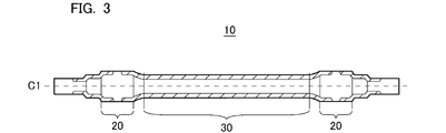
- FIG. 3 is a cross-sectional view of a crude product in this embodiment.
- FIG. 4 is a side view of a railroad axle in this embodiment.
- FIG. 5 is a schematic view of a fatigue test device for a railway axle 1 in this embodiment.
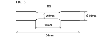
- FIG. 6 is a cross-sectional view of the test material used in this embodiment.
- FIG. 7 is a cross-sectional view of the fatigue test piece used in this example.
- the present inventors performed induction hardening to form a hardened layer (hereinafter, also referred to as "fitting part hardened layer”) on the surface layer of the fitting part, and suppressed fretting fatigue in the fitting part.
- a hardened layer hereinafter, also referred to as "fitting part hardened layer”
- fretting fatigue for the axle, we investigated and examined a method to increase the fatigue strength of the central parallel part. As a result, the following findings were obtained.
- a hardened layer (hereinafter, also referred to as “central parallel portion hardened layer”) is formed on the surface layer of the central parallel portion. If the hardened layer in the central parallel portion is formed, it is considered that the hardness of the surface layer in the central parallel portion is increased and the fatigue strength in the central parallel portion is increased. Therefore, the present inventors first examined in detail the chemical composition capable of sufficiently increasing the fatigue strength of the central parallel portion on the premise of forming the central parallel portion cured layer.
- the chemical composition of the base metal part inside the hardened layer in the central parallel part of the railroad axle is C: 0.22 to 0.29%, Si: 0.15 to 0.40 in mass%. %, Mn: 0.50 to 0.80%, P: 0.020% or less, S: 0.040% or less, Cr: 0.90 to 1.20%, Mo: 0.15 to 0.30% , N: 0.0200% or less, O: 0.0040% or less, Ca: 0 to 0.0010%, Cu: 0 to 0.30%, Ni: 0 to 0.30%, Al: 0 to 0.
- V 0 to 0.060%
- Ti 0 to 0.020%
- Nb 0 to 0.030%
- B 0 to 0.0050%
- the balance is Fe and impurities. It was considered that the fatigue strength of the central parallel portion where the central parallel portion cured layer was formed could be increased by high frequency quenching.
- the present inventors performed induction hardening and tempering on a steel material in the shape of a railway axle having the above-mentioned chemical composition, and for railways having a hardened layer in a fitted portion and a hardened layer in a central parallel portion.
- Various axles were manufactured.
- the fatigue strength of the central parallel portion may be different.
- the inventors have found out. That is, it has been clarified by the studies by the present inventors that the fatigue strength in the central parallel portion cannot be sufficiently increased by simply increasing the hardness of the central parallel portion cured layer.
- the Vickers hardness is 480 HV or more, which is very high, so that the dislocation density tends to be high.
- dislocations may move and accumulate, which may be the starting point of cracks. That is, in a specific hardness region where the dislocation density is high, dislocations tend to accumulate and fatigue strength tends to decrease. Therefore, if the dislocation density is reduced in the specific hardness region where the dislocation density is high, the accumulation of dislocations that are the starting points of cracks is less likely to occur, and the fatigue strength may increase.
- the base metal portion has the above-mentioned chemical composition, and the dislocation density ⁇ obtained based on the Co—K ⁇ characteristic X-ray diffraction result in the specific hardness region is 2. .5 ⁇ 10 16 m -2 or less.
- the central parallel portion has a base material portion having the above-mentioned chemical composition and a central parallel portion cured layer, and the Co—K ⁇ characteristic X in the specific hardness region of the central parallel portion cured layer. Even if the dislocation density ⁇ obtained based on the linear diffraction result is 2.5 ⁇ 10 16 m ⁇ 2 or less, the fatigue strength may not be sufficiently increased. Therefore, the present inventors have investigated and examined a method for increasing the fatigue strength of the central parallel portion, focusing on the lattice strain.
- the (211) diffraction plane is caused by the solid dissolution and precipitation of carbon (C) by induction hardening and tempering. , Changes in the c-axis of the crystal lattice can be observed. Therefore, the present inventors investigated and examined the relationship with the fatigue strength of the central parallel portion, focusing on (211) the half-value width of the diffractive surface as an index of the lattice strain in the specific hardness region.
- the specific hardness region is formed by performing induction hardening.
- induction hardening involves transformation of the microstructure of the steel material, it is considered that microscopic distortion occurs in the crystal lattice in the microstructure of the steel material that has been induction hardened.
- dislocations moved by stress may easily stay.
- dislocations may accumulate at the region where the lattice strain is large, which may be the starting point of cracks.
- the Co—K ⁇ characteristic X in the specific hardness region X If the half-value width B of the (211) diffraction surface due to line diffraction is reduced to 1.34 degrees or less, the fatigue strength of the central parallel portion may be increased provided that the other configurations according to the present embodiment are satisfied. It became clear that there was.
- the base metal portion has the above-mentioned chemical composition, and the dislocation density ⁇ obtained based on the Co—K ⁇ characteristic X-ray diffraction result in the specific hardness region is obtained. 2.5 ⁇ 10 16 m -2 or less, and further, the half-value width B of the (211) diffraction surface by Co—K ⁇ characteristic X-ray diffraction is set to 1.34 degrees or less.
- the dislocation density ⁇ obtained based on the Co-K ⁇ characteristic X-ray diffraction result and the half-value width B of the (211) diffraction surface by the Co-K ⁇ characteristic X-ray diffraction are obtained. It was clarified that the fatigue strength of the central parallel portion can be stably increased by satisfying the following equation (1).
- Fn1 (-4.8 ⁇ 10 16 ⁇ B + 8.5 ⁇ 10 16 ) / ⁇ .
- Fn1 is an index indicating the degree of accumulation of dislocations in a specific hardness region. When Fn1 is less than 1.00, dislocations are accumulated in a specific hardness region to which repeated stress is applied, which is the starting point of cracks. As a result, sufficient fatigue strength cannot be obtained in the central parallel portion. On the other hand, when Fn1 is 1.00 or more, the accumulation of dislocations is suppressed even in the specific hardness region to which repeated stress is applied, and the fatigue strength in the central parallel portion can be increased.
- the present inventors consider the reason for this as follows. As described above, in the central parallel portion having the base material portion having the above-mentioned chemical composition and the central parallel portion cured layer, dislocations may move due to repeated stress, and cracks may occur. That is, if dislocations become denser and cracks and slips can be suppressed rather than simply reducing the dislocation density, the fatigue strength of the central parallel portion may be increased. Therefore, in the railroad axle according to the present embodiment, the dislocation density ⁇ obtained based on the Co—K ⁇ characteristic X-ray diffraction result is 2.5 ⁇ 10 16 m -2 or less in the specific hardness region where the dislocation density tends to be high.
- the half-value width B of the (211) diffraction surface by Co—K ⁇ characteristic X-ray diffraction is set to 1.34 degrees or less, and Fn1 is further set to 1.00 or more.
- the railroad axle according to the present embodiment in the central parallel portion having the base material portion having the above-mentioned chemical composition and the central parallel portion cured layer, based on the Co—K ⁇ characteristic X-ray diffraction result in the specific hardness region.
- the obtained shift density ⁇ is 2.5 ⁇ 10 16 m -2 or less
- the half-value width B of the (211) diffraction surface by Co-K ⁇ characteristic X-ray diffraction is 1.34 degrees or less
- Co- Co-.
- the railroad axle according to the present embodiment has excellent fatigue strength in the central parallel portion.
- the gist of the railroad axle of this embodiment completed based on the above knowledge is as follows.
- the fitting part is The hardened layer of the fitted portion formed on the surface layer of the fitted portion and the cured layer of the fitting portion.
- the fitting portion includes the base material portion inside the hardened layer, and includes the base metal portion.
- the central parallel portion is The central parallel portion cured layer formed on the surface layer of the central parallel portion, The base material portion inside the central parallel portion cured layer is included.
- the base material portion is by mass%.
- the dislocation density ⁇ obtained based on the Co-K ⁇ characteristic X-ray diffraction result is 2.5 ⁇ 10 16 m -2 or less.
- the half-value width B of the (211) diffraction surface by Co-K ⁇ characteristic X-ray diffraction is 1.34 degrees or less.
- the shift density ⁇ obtained based on the Co—K ⁇ characteristic X-ray diffraction result and the half-value width B of the (211) diffraction surface by the Co—K ⁇ characteristic X-ray diffraction satisfy the formula (1).
- Railroad axle
- the base material portion is by mass%.
- FIG. 1 is a side view of a railroad axle according to the present embodiment.
- the railroad axle 1 of the present embodiment includes a pair of fitting portions 2A and 2B and a central parallel portion 3.
- Each of the pair of fitting portions 2A and 2B is a cylinder having a diameter D W.
- the central axes of the fitting portions 2A and 2B coincide with the central axis C1 of the railroad axle 1.
- the central axis C1 of the railroad axle 1 extends in the longitudinal direction of the railroad axle 1.
- the "central axis C1 direction" of the railway axle 1 is synonymous with the "longitudinal direction" of the railway axle 1.
- the fitting portion 2A is connected to the left end of the central parallel portion 3 in FIG.
- the fitting portion 2B is connected to the right end of the central parallel portion 3 in FIG.
- fitting portion 2 when the fitting portions 2A and 2B are generically referred to, they are referred to as "fitting portion 2".
- Railroad wheels (not shown) are press-fitted into each fitting portion 2.
- the central parallel portion 3 is arranged between the pair of fitting portions 2A and 2B.
- the left end of the central parallel portion 3 is connected to the fitting portion 2A arranged on the left portion of the railway axle 1.
- the right end of the central parallel portion 3 is connected to the fitting portion 2B arranged on the right portion of the railway axle 1.
- the central parallel portion 3 is a cylinder having a diameter DA .
- the diameter DA of the central parallel portion 3 is smaller than the diameter D W of the fitting portion 2.
- the central axis of the central parallel portion 3 coincides with the central axis C1 of the railway axle 1. In short, the central parallel portion 3 is arranged coaxially with the pair of fitting portions 2.
- the pair of fitting portions 2 may be solid or hollow.
- the central parallel portion 3 may be solid or hollow.
- the diameter DA of the central parallel portion is not particularly limited, but is, for example, 100 to 200 mm.
- the diameter D W of the fitting portion 2 is not particularly limited, but is, for example, 110 to 260 mm.
- the railroad axle 1 further continuously connects the central parallel portion 3 and the fitting portion 2 between the end portion of the central parallel portion 3 and the inner end of the fitting portion 2.
- a tapered portion 4 is provided.
- the diameter of the tapered portion 4 increases from the end portion of the central parallel portion 3 toward the inner end of the fitting portion 2 in the direction of the central axis C1 of the railroad axle 1.
- the surface of the tapered portion 4 may be curved or linear.
- the railroad axle 1 does not have to be provided with the tapered portion 4.
- the end portion of the central parallel portion 3 is connected to the inner end of the fitting portion 2, and a step is formed between the end portion of the central parallel portion 3 and the inner end of the fitting portion 2.
- FIG. 2 is a cross-sectional view of the railroad axle 1 of the present embodiment shown in FIG. 1 including the central axis C1.
- each of the fitting portions 2 (2A and 2B) has a fitting portion cured layer 2H formed on the surface layer and a base material portion BM inside the fitting portion cured layer 2H. including.
- the fitting portion cured layer 2H is formed on the surface layer in a range from the surface of the fitting portion 2 to a predetermined depth.
- the fitting portion cured layer 2H does not have to be formed on the entire surface of the fitting portion 2.
- the fitted portion hardened layer 2H is a part of a region outside the center position of the fitting portion 2 and inside the center position of the fitting portion 2 in the direction of the central axis C1 of the railroad axle 1.
- the fitted portion hardened layer 2H is not formed in a part of the region including the central position of the fitted portion 2.
- the hardened layer 2H of the fitting portion does not have to be formed on the entire surface of the fitting portion 2, and is formed in at least a part of the surface of the fitting portion 2 in the direction of the central axis C1. You may.
- the fitting portion cured layer 2H may be formed on the entire surface of the fitting portion 2. The fitted portion cured layer 2H will be described later.
- the central parallel portion 3 includes a central parallel portion cured layer 3H formed on the surface layer of the central parallel portion 3 and a base material portion BM inside the central parallel portion cured layer 3H.
- the central parallel portion cured layer 3H is formed on the surface layer in a range from the surface of the central parallel portion 3 to a predetermined depth.
- the central parallel portion cured layer 3H is formed on the entire surface of the central parallel portion 3. The central parallel portion cured layer 3H will be described later.
- the chemical composition of the base material portion BM of the pair of fitting portions 2 and the chemical composition of the base material portion BM of the central parallel portion 3 contain the following elements.
- a line segment connecting the surface of the railway axle 1 and the central axis C1 in a cross section perpendicular to the central axis C1 of the railway axle 1 is defined as a radius R.
- the chemical composition of the base metal portion BM means the chemical composition at the R / 2 position of the fitting portion 2 and the R / 2 position of the central parallel portion 3.
- % with respect to an element means mass% unless otherwise specified.
- C 0.22 to 0.29% Carbon (C) increases the hardness of steel. C further increases the hardness of the cured layer by induction hardening. If the C content is less than 0.22%, the hardness of the base material portion BM, the fitting portion cured layer 2H, and the central parallel portion cured layer 3H is hard even if the other element content is within the range of the present embodiment. Decreases. As a result, the fatigue strength of the central parallel portion 3 may decrease. On the other hand, if the C content exceeds 0.29%, quench cracking may occur during induction hardening even if the content of other elements is within the range of the present embodiment. Therefore, the C content is 0.22 to 0.29%.
- the lower limit of the C content is preferably 0.23%, more preferably 0.24%.
- the preferred upper limit of the C content is 0.28%, more preferably 0.27%.
- Si 0.15 to 0.40% Silicon (Si) deoxidizes steel. Si further increases the temper softening resistance of the steel and increases the fatigue strength in the central parallel portion 3. If the Si content is less than 0.15%, these effects cannot be sufficiently obtained even if the content of other elements is within the range of the present embodiment. On the other hand, if the Si content exceeds 0.40%, quench cracking may occur during induction hardening even if the content of other elements is within the range of the present embodiment. Therefore, the Si content is 0.15 to 0.40%.
- the lower limit of the Si content is preferably 0.20%, more preferably 0.23%, still more preferably 0.25%.
- the preferred upper limit of the Si content is 0.37%, more preferably 0.35%, still more preferably 0.33%.
- Mn 0.50 to 0.80%
- Manganese (Mn) enhances the hardenability of steel and thickens the hardened layers 2H and 3H by induction hardening. If the Mn content is less than 0.50%, the central parallel portion cured layer 3H may become too thin even if the other element content is within the range of the present embodiment. In this case, the fatigue strength in the central parallel portion 3 cannot be sufficiently obtained. On the other hand, if the Mn content exceeds 0.80%, the fitting portion cured layer 2H and the central parallel portion cured layer 3H formed by induction hardening are formed even if the other element content is within the range of the present embodiment. May become too thick.
- the Mn content is 0.50 to 0.80%.
- the preferred lower limit of the Mn content is 0.55%, more preferably 0.57%, still more preferably 0.60%, still more preferably 0.62%.
- the preferred upper limit of the Mn content is 0.78%, more preferably 0.75%, still more preferably 0.73%, still more preferably 0.70%.
- Phosphorus (P) is an impurity that is inevitably contained. That is, the P content is more than 0%. P segregates at the grain boundaries and reduces the fatigue strength of the steel. If the P content exceeds 0.020%, the fatigue strength of the railroad axle 1 will decrease even if the content of other elements is within the range of this embodiment. Therefore, the P content is 0.020% or less.
- the preferred upper limit of the P content is 0.018%, more preferably 0.016%, still more preferably 0.015%, still more preferably 0.014%. It is preferable that the P content is as low as possible. However, an extreme reduction in P content significantly increases manufacturing costs. Therefore, when industrial production is taken into consideration, the preferable lower limit of the P content is 0.001%, and more preferably 0.002%.
- S 0.040% or less Sulfur (S) is an impurity that is inevitably contained. That is, the S content is more than 0%. S combines with Mn to generate MnS. MnS reduces the fatigue strength of steel. When the S content exceeds 0.040%, stress concentrates on MnS and the fatigue strength of the central parallel portion 3 decreases even if the content of other elements is within the range of this embodiment. Therefore, the S content is 0.040% or less.
- the upper limit of the S content is preferably 0.030%, more preferably 0.020%, still more preferably 0.015%, still more preferably 0.010%. It is preferable that the S content is as low as possible. However, an extreme reduction in S content significantly increases manufacturing costs. Therefore, when industrial production is taken into consideration, the preferable lower limit of the S content is 0.001%, and more preferably 0.002%.
- Chromium (Cr) enhances the hardenability of steel and enhances the hardness of the hardened layer 2H in the fitted portion and the hardened layer 3H in the central parallel portion by induction hardening. If the Cr content is less than 0.90%, the central parallel portion cured layer 3H may become too thin. In this case, the fatigue strength in the central parallel portion 3 decreases. On the other hand, if the Cr content exceeds 1.20%, the fitted portion hardened layer 2H and the central parallel portion hardened layer 3H formed by induction hardening even if the other element content is within the range of the present embodiment. May become too thick.
- the Cr content is 0.90 to 1.20%.
- the lower limit of the Cr content is preferably 0.95%, more preferably 1.00%, still more preferably 1.02%, still more preferably 1.05%.
- the preferred upper limit of the Cr content is 1.19%, more preferably 1.17%, still more preferably 1.15%.
- Mo 0.15 to 0.30% Molybdenum (Mo) increases the strength of steel. If the Mo content is less than 0.15%, this effect cannot be sufficiently obtained even if the content of other elements is within the range of the present embodiment. On the other hand, if the Mo content exceeds 0.30%, the above effect is saturated even if the content of other elements is within the range of the present embodiment. If the Mo content exceeds 0.30%, the manufacturing cost will be excessively increased. Therefore, the Mo content is 0.15 to 0.30%.
- the lower limit of the Mo content is preferably 0.17%, more preferably 0.19%, still more preferably 0.20%, still more preferably 0.21%.
- the preferred upper limit of the Mo content is 0.29%, more preferably 0.28%, still more preferably 0.27%.
- N Nitrogen (N) is inevitably contained. That is, the N content is more than 0%. N combines with Al and the like to form fine nitrides and refines the crystal grains. However, if the N content is too high, coarse nitrides will be formed and the fatigue strength of the steel will decrease. If the N content exceeds 0.0200%, the fatigue strength of the railroad axle 1 will decrease even if the content of other elements is within the range of this embodiment. Therefore, the N content is 0.0200% or less.
- the preferred upper limit of the N content is 0.0150%, more preferably 0.0120%, still more preferably 0.0100%, still more preferably 0.0090%, still more preferably 0.0080. %, More preferably 0.0070%. In order to obtain the above effect more effectively, the lower limit of the N content is preferably 0.0010%, more preferably 0.0020%, still more preferably 0.0030%.
- Oxygen (O) is an impurity that is inevitably contained. That is, the O content is more than 0%. O produces a coarse oxide and may be the starting point of fatigue fracture. If the O content exceeds 0.0040%, the fatigue strength in the central parallel portion 3 decreases even if the content of other elements is within the range of the present embodiment. Therefore, the O content is 0.0040% or less.
- the preferred upper limit of the O content is 0.0030%, more preferably 0.0025%, still more preferably 0.0020%, still more preferably 0.0015%. It is preferable that the O content is as low as possible. However, an extreme reduction in O content significantly increases manufacturing costs. Therefore, when industrial production is taken into consideration, the preferable lower limit of the O content is 0.0001%, more preferably 0.0002%, still more preferably 0.0005%.
- Ca 0 to 0.0010%
- Calcium (Ca) is an impurity. Ca may not be contained. That is, the Ca content may be 0%. Ca aggregates silicate-based inclusions (Group C defined in JIS G 0555 (2003)) and reduces the fatigue strength of steel. If the Ca content exceeds 0.0010%, the silicate-based inclusions become the starting point of fatigue fracture and the fatigue strength in the central parallel portion 3 decreases even if the content of other elements is within the range of the present embodiment. .. Therefore, the Ca content is 0 to 0.0010%. The preferred upper limit of the Ca content is 0.0006%, more preferably 0.0004%, still more preferably 0.0003%.
- the balance of the chemical composition of the base material portion BM of the fitting portion 2 and the central parallel portion 3 of the railroad axle 1 according to the present embodiment is Fe and impurities.
- the impurities are mixed from ore, scrap, manufacturing environment, etc. as a raw material when the steel material of the railroad axle 1 is industrially manufactured, and the railroad axle 1 of the present embodiment. It means something that is acceptable as long as it does not adversely affect.
- the chemical composition of the base material portion BM of the fitting portion 2 and the central parallel portion 3 of the railroad axle 1 according to the present embodiment is further selected from the group consisting of Cu and Ni instead of a part of Fe1. It may contain more than an element. These elements are optional elements and all increase the strength of steel.
- Cu 0 to 0.30% Copper (Cu) is an optional element and may not be contained. That is, the Cu content may be 0%. When Cu is contained, Cu increases the strength of the steel. If even a small amount of Cu is contained, this effect can be obtained to some extent. However, if the Cu content exceeds 0.30%, the hot workability of the steel is lowered even if the content of other elements is within the range of this embodiment. Therefore, the Cu content is 0 to 0.30%.
- the lower limit of the Cu content is more than 0%, more preferably 0.01%, still more preferably 0.02%.
- the preferred upper limit of the Cu content is 0.25%, more preferably 0.20%, still more preferably 0.15%, still more preferably 0.10%, still more preferably 0.05. %.
- Nickel (Ni) is an optional element and may not be contained. That is, the Ni content may be 0%. When Ni is contained, Ni increases the strength of the steel. If even a small amount of Ni is contained, this effect can be obtained to some extent. However, if the Ni content exceeds 0.30%, the above effect is saturated even if the content of other elements is within the range of the present embodiment. Therefore, the Ni content is 0 to 0.30%.
- the lower limit of the Ni content is more than 0%, more preferably 0.01%, still more preferably 0.02%, still more preferably 0.04%.
- the upper limit of the Ni content is preferably 0.25%, more preferably less than 0.20%, still more preferably 0.15%, still more preferably 0.10%.
- the chemical composition of the base material portion BM of the fitting portion 2 and the central parallel portion 3 of the railroad axle 1 according to the present embodiment may further contain Al instead of a part of Fe.
- Al 0 to 0.100%
- Aluminum (Al) is an optional element and may not be contained. That is, the Al content may be 0%. When Al is contained, Al deoxidizes the steel. Al further combines with N to form AlN and refines the crystal grains. As a result, the toughness of steel is increased. If Al is contained even in a small amount, these effects can be obtained to some extent. However, if the Al content exceeds 0.100%, coarse oxide-based inclusions are generated even if the content of other elements is within the range of the present embodiment, and the fatigue strength of the railroad axle 1 becomes high. descend. Therefore, the Al content is 0 to 0.100%.
- the lower limit of the Al content is more than 0%, more preferably 0.005%, still more preferably 0.007%, still more preferably 0.010%, still more preferably 0.015%. It is more preferably 0.020%.
- the preferred upper limit of the Al content is 0.080%, more preferably 0.060%, still more preferably 0.050%, still more preferably 0.045%, still more preferably 0.040. %.
- the Al content means the content of acid-soluble Al (sol.Al).
- the chemical composition of the base material portion BM of the fitting portion 2 and the central parallel portion 3 of the railroad axle 1 according to the present embodiment is further selected from the group consisting of V, Ti, and Nb instead of a part of Fe. It may contain one or more elements. These elements are optional elements and all increase the strength of steel.
- V Vanadium (V) is an optional element and may not be contained. That is, the V content may be 0%. When V is contained, V combines with N or C to form V (C, N). In this case, the crystal grains are refined and the strength of the steel is increased. If even a small amount of V is contained, this effect can be obtained to some extent. However, if the V content exceeds 0.060%, the toughness of the steel will decrease even if the content of other elements is within the range of this embodiment. Therefore, the V content is 0 to 0.060%.
- the lower limit of the V content is preferably more than 0%, more preferably 0.005%, still more preferably 0.008%, still more preferably 0.010%.
- the preferred upper limit of the V content is 0.055%, more preferably 0.050%, still more preferably 0.045%, still more preferably 0.040%.
- Titanium (Ti) is an optional element and may not be contained. That is, the Ti content may be 0%. When Ti is contained, Ti combines with N to produce fine TiN. TiN increases the strength of steel. TiN further refines the crystal grains and increases the fatigue strength of the steel. If even a small amount of Ti is contained, this effect can be obtained to some extent. However, if the Ti content exceeds 0.020%, even if the content of other elements is within the range of this embodiment, the TiN precipitate becomes a crack path and the toughness of the steel is lowered. Therefore, the Ti content is 0 to 0.020%.
- the lower limit of the Ti content is more than 0%, more preferably 0.002%, still more preferably 0.003%.
- the preferred upper limit of the Ti content is 0.018%, more preferably 0.015%, even more preferably 0.013%, still more preferably 0.010%, still more preferably 0.007. %.
- Niobium (Nb) is an optional element and may not be contained. That is, the Nb content may be 0%. When Nb is contained, Nb binds to N or C to form Nb (C, N). In this case, Nb (C, N) refines the crystal grains and enhances the strength and toughness of the steel. If even a small amount of Nb is contained, this effect can be obtained to some extent. However, if the Nb content exceeds 0.030%, the carbides and / or carbonitrides produced in the steel may be coarsened even if the content of other elements is within the range of this embodiment. There is. In this case, the toughness of the steel is rather lowered.
- the Nb content is 0 to 0.030%.
- the preferable lower limit of the Nb content is more than 0%, more preferably 0.002%, still more preferably 0.003%, still more preferably 0.005%.
- the preferred upper limit of the Nb content is 0.029%, more preferably 0.027%, still more preferably 0.025%, still more preferably 0.020%.
- the chemical composition of the base material portion BM of the fitting portion 2 and the central parallel portion 3 of the railroad axle 1 according to the present embodiment may further contain B instead of a part of Fe.
- B 0 to 0.0050% Boron (B) is an optional element and may not be contained. That is, the B content may be 0%. When B is contained, B enhances the hardenability of steel. If B is contained even in a small amount, this effect can be obtained to some extent. On the other hand, if the B content exceeds 0.0050%, the toughness of the steel is lowered even if the content of other elements is within the range of the present embodiment. Therefore, the B content is 0 to 0.0050%.
- the lower limit of the B content is preferably more than 0%, more preferably 0.0003%, still more preferably 0.0005%, still more preferably 0.0007%.
- the preferred upper limit of the B content is 0.0040%, more preferably 0.0030%, still more preferably 0.0020%.
- the microstructure of the base material portion BM is mainly composed of martensite and bainite.
- martensite and bainite means that the total area ratio of martensite and bainite is 80% or more in the microstructure.
- martensite also includes tempered martensite.
- Bainite includes tempered bainite.
- the rest other than martensite and bainite is, for example, ferrite.
- the microstructure of the base metal portion BM of the railway axle 1 corresponds to the microstructure of the surface layer portion of the railway axle before induction hardening. If the microstructure of the base material portion BM of the railroad axle 1 is mainly martensite and bainite, the hardness of the surface layer portion of the railroad axle 1 increases. If the microstructure is mainly martensite and bainite, the microstructure on the surface layer is rapidly austenitized during high-frequency heating. In this case, the martensite fraction of the cured layer formed by induction hardening increases, and the hardness of the cured layer increases. As a result, the fatigue strength of the railway axle 1 after induction hardening is further increased.
- the total area ratio of martensite and bainite in the microstructure of the base material portion BM of the railroad axle 1 can be obtained by the following method.
- Five samples for microstructure observation are collected from the R / 2 position of the cross section perpendicular to the central axis C1 direction of the fitting portion 2 or the central parallel portion 3.
- the cross section perpendicular to the central axis C1 is used as the observation surface.
- One field of view is 40,000 ⁇ m 2 (magnification: 500 times), and one field of view (that is, five fields of view in total using five samples) is observed for each sample.
- martensite and bainite and phases other than martensite and bainite are identified based on the contrast. It is difficult to distinguish between martensite and bainite by contrast. However, martensite and bainite and phases other than martensite and bainite such as ferrite can be easily distinguished by contrast.
- the total area ratio of martensite and bainite in each visual field is obtained.
- the arithmetic mean value of the total area ratio of martensite and bainite obtained in each field of view is defined as the total area ratio (%) of martensite and bainite.
- the fitting portion hardened layer 2H is formed in each of the pair of fitting portions 2.
- the central parallel portion hardened layer 3H is further formed in the central parallel portion 3.
- the term "hardened layer” means a region formed by induction hardening and having an increased Vickers hardness as compared with the base metal portion BM.
- the fitted portion cured layer 2H and the central parallel portion cured layer 3H are defined as the effective cured layer depth in JIS G 0559 (2008), and the critical hardness is 350 HV in Vickers hardness. Is defined as the area of.
- the limit hardness of the fitted portion cured layer 2H and the central parallel portion cured layer 3H is 350 HV in Vickers hardness.
- the microstructure of the hardened layer 2H in the fitted part and the hardened layer 3H in the central parallel part is mainly composed of martensite and bainite.
- martensite and bainite means that the total area ratio of martensite and bainite is 80% or more in the microstructure.
- martensite also includes tempered martensite.
- Bainite includes tempered bainite.
- the total area ratio of martensite and bainite in the microstructure of the fitted portion hardened layer 2H and the central parallel portion hardened layer 3H of the railway axle 1 is the microstructure of the base material portion BM of the railway axle 1 according to the present embodiment. It can be calculated in the same way as the total area ratio of martensite and bainite.
- five samples for microstructure observation are collected from the fitted portion cured layer 2H and / or the central parallel portion cured layer 3H identified by the above method.
- the cross section perpendicular to the central axis C1 is used as the observation surface. After polishing the observation surface of each sample to a mirror surface, it is immersed in a nital corrosive solution for about 10 seconds to reveal the microstructure by etching. Observe the etched observation surface with an optical microscope.
- One field of view is 40,000 ⁇ m 2 (magnification: 500 times), and one field of view (that is, five fields of view in total using five samples) is observed for each sample.
- a region having a Vickers hardness of 480 HV or more in the central parallel portion cured layer 3H is defined as a “specific hardness region”.
- the limit hardness of the central parallel portion cured layer 3H is 350 HV in Vickers hardness. That is, the specific hardness region means a region having a particularly high hardness in the central parallel portion cured layer 3H.
- the specific hardness region can be specified by the following method.
- a Vickers hardness test conforming to JIS Z 2244 (2009) was carried out at a load of 2.9 N and a pitch of 0.1 mm for the central parallel portion hardened layer 3H according to the present embodiment, and the Vickers hardness (HV) was obtained.
- HV Vickers hardness
- the Vickers hardness (HV) in the radial direction (depth direction) of the railway axle 1 from the surface of the central parallel portion 3 with respect to the surface obtained by cutting perpendicular to the central axis C1 of the railway axle 1. ) May be measured.
- a region of 480 HV or more in Vickers hardness is specified from the surface of the railway axle 1.
- a region having a specified Vickers hardness of 480 HV or higher is defined as a specific hardness region.
- the dislocation density ⁇ obtained based on the Co—K ⁇ characteristic X-ray diffraction result is 2.5 ⁇ in the region where the Vickers hardness is 480 HV or more in the central parallel portion hardened layer 3H. It is 10 16 m -2 or less.
- a region having a Vickers hardness of 480 HV or more is referred to as a specific hardness region.
- the dislocation density ⁇ obtained based on the Co—K ⁇ characteristic X-ray diffraction result in the specific hardness region of the central parallel portion cured layer 3H is 2.5 ⁇ 10 16 m ⁇ 2 or less.
- the specific hardness region is a region having a particularly high hardness in the central parallel portion cured layer 3H. Therefore, the dislocation density tends to be high in the specific hardness region.
- dislocations may move through the steel material under repeated stress and become the starting point of cracks. That is, it is considered that the higher the dislocation density ⁇ obtained based on the Co—K ⁇ characteristic X-ray diffraction result, the more likely the crack origin is to occur and the fatigue intensity is likely to decrease. Therefore, in the railway axle 1 according to the present embodiment, the dislocation density ⁇ obtained based on the Co—K ⁇ characteristic X-ray diffraction result in the specific hardness region of the central parallel portion hardened layer 3H is 2.5 ⁇ 10 16 . It shall be m -2 or less. As a result, the central parallel portion 3 has excellent fatigue strength, provided that the other configurations of the railroad axle 1 according to the present embodiment are satisfied.
- the preferable upper limit of the dislocation density ⁇ obtained based on the Co—K ⁇ characteristic X-ray diffraction result in the specific hardness region of the central parallel portion cured layer 3H is 2.4 ⁇ 10 16 m ⁇ 2 .
- the lower limit of the dislocation density ⁇ obtained based on the Co—K ⁇ characteristic X-ray diffraction result in the specific hardness region of the central parallel portion cured layer 3H is not particularly limited. However, if the dislocation density is too low, the Vickers hardness of 480 HV or higher, which is defined as a specific hardness region, may not be obtained.
- the lower limit of the dislocation density ⁇ obtained based on the Co—K ⁇ characteristic X-ray diffraction result in the specific hardness region of the central parallel portion cured layer 3H is, for example, 1.4 ⁇ 10 16 m ⁇ 2 . Is.
- the dislocation density ⁇ obtained based on the Co—K ⁇ characteristic X-ray diffraction result can be obtained by the following method.
- a specific hardness region is specified by the above-mentioned method from the central parallel portion 3 of the railroad axle 1 according to the present embodiment.
- a test piece for measuring the dislocation density is prepared from a specific hardness region.
- the size of the test piece is not particularly limited, but is, for example, 10 mm in the circumferential direction ⁇ 20 mm in the axial direction ⁇ 5 mm in the radial direction with respect to the railroad axle 1.
- the thickness direction of the test piece is the radial direction (depth direction) of the railway axle 1.
- the observation surface of the test piece is a surface of 10 mm in the circumferential direction ⁇ 20 mm in the axial direction with respect to the railroad axle 1.
- the observation surface of the test piece is mechanically polished and then electrolytically polished to remove surface strain.
- a diffraction profile is obtained by X-ray diffraction (XRD) on the observation surface after electrolytic polishing.
- XRD X-ray diffraction
- the radiation source is CoK ⁇ ray
- the tube voltage is 30 kV
- the tube current is 100 mA.
- the measurement was performed at a pitch of 0.02 degrees with a diffraction angle (2 ⁇ ) in the range of 45 to 105 degrees, and in 0.6 seconds per point.
- the calibration of the peak position corresponding to the diffraction angle can be performed by confirming that the diffraction peak position of the specific surface does not deviate from the reference position using a Si standard plate.
- the half-value range is corrected by using LaB 6 (lanthanum hexaboride) as a standard sample and measuring the width of the device in advance.
- the peak position (2 ⁇ ) and the half-value width (B') are obtained for the (110), (211), and (220) diffraction planes, respectively.
- the non-uniform strain ⁇ is obtained from the obtained peak position (2 ⁇ ) of each diffraction plane, the half-value width (B') of each diffraction plane, and the Williamson-Hall equation (Equation (2)).
- B' ⁇ cos ⁇ / ⁇ 0.9 / D + 2 ⁇ ⁇ sin ⁇ / ⁇ (2)
- ⁇ means the diffraction angle
- ⁇ means the wavelength of the X-ray (0.1788895 nm)
- D the crystallite diameter.
- the dislocation density ⁇ (m -2 ) obtained based on the Co—K ⁇ characteristic X-ray diffraction result can be obtained.
- ⁇ 14.4 ⁇ ⁇ 2 / b 2 (3)
- b means a Burgers vector (0.25 nm) of a body-centered cubic structure (iron).
- the half-value width B of the (211) diffraction surface by Co—K ⁇ characteristic X-ray diffraction is 1. It is 34 degrees or less.
- the half-value width B of the (211) diffraction plane by the Co—K ⁇ characteristic X-ray diffraction is an index of the microscopic distortion of the crystal lattice.
- the specific hardness region has a particularly high hardness among the central parallel portion cured layer 3H, and the dislocation density tends to be high. Therefore, as described above, in the present embodiment, the dislocation density ⁇ obtained based on the Co—K ⁇ characteristic X-ray diffraction result in the specific hardness region is reduced to 2.5 ⁇ 10 16 m ⁇ 2 or less. However, even if the dislocation density ⁇ obtained based on the Co-K ⁇ characteristic X-ray diffraction result in the specific hardness region is reduced to 2.5 ⁇ 10 16 m -2 or less, the microscopic distortion of the crystal lattice remains. Dislocations tend to stay in the locally large regions due to repeated stress. Therefore, in the railroad axle 1 according to the present embodiment, the microscopic distortion of the crystal lattice is reduced in the specific hardness region of the central parallel portion hardened layer 3H.
- the base metal portion has the above-mentioned chemical composition, and the Co—K ⁇ characteristic X-ray diffraction result in the specific hardness region of the central parallel portion hardened layer 3H.
- the shift density ⁇ obtained based on the above is 2.5 ⁇ 10 16 m ⁇ 2 or less, and the half-value width B of the (211) diffraction surface by Co—K ⁇ characteristic X-ray diffraction is 1.34 degrees or less.
- the preferred upper limit of the half-value width B of the (211) diffraction surface by Co—K ⁇ characteristic X-ray diffraction in the specific hardness region of the central parallel portion cured layer 3H is 1.33 degrees, more preferably 1.33 degrees. It is 1.32 degrees.
- the lower limit of the half-value width B of the (211) diffraction surface by Co—K ⁇ characteristic X-ray diffraction is not particularly limited.
- the lower limit of the half-value width B of the (211) diffraction surface by Co—K ⁇ characteristic X-ray diffraction in the specific hardness region of the central parallel portion cured layer 3H is, for example, 0.9 degrees.
- the half-value width B of the (211) diffraction surface by Co-K ⁇ characteristic X-ray diffraction can be obtained by the following method.
- a test piece is prepared under the same conditions as in the case of obtaining the shift density ⁇ obtained based on the above-mentioned Co-K ⁇ characteristic X-ray diffraction result, and the shift density ⁇ obtained based on the above-mentioned Co-K ⁇ characteristic X-ray diffraction result.
- a diffraction profile is obtained by XRD under the same conditions as in the case of obtaining. From the obtained diffraction profile, the peak of the (211) diffraction plane is specified, and the half price range thereof is obtained.
- the obtained half-value width is defined as the half-value width B of the (211) diffraction plane by Co-K ⁇ characteristic X-ray diffraction.
- the half-value width B of the (211) diffraction surface by the characteristic X-ray diffraction satisfies the equation (1).
- Fn1 is less than 1.00, dislocations are accumulated in a specific hardness region to which repeated stress is applied, which is the starting point of cracks. As a result, sufficient fatigue strength cannot be obtained in the central parallel portion.
- Fn1 is 1.00 or more, the accumulation of dislocations is suppressed even in the specific hardness region to which repeated stress is applied, and the fatigue strength in the central parallel portion can be increased.
- the base metal portion has the above-mentioned chemical composition, and the Co—K ⁇ characteristic X-ray diffraction result in the specific hardness region of the central parallel portion hardened layer 3H.
- the dislocation density ⁇ obtained based on the above is 2.5 ⁇ 10 16 m -2 or less
- the half-value width B of the (211) diffraction surface by Co—K ⁇ characteristic X-ray diffraction is 1.34 degrees or less
- Fn1 is 1.00 or more.
- the preferable lower limit of Fn1 is 1.01, and more preferably 1.03.
- the upper limit of Fn1 is not particularly limited. In this embodiment, the upper limit of Fn1 is, for example, 3.0.
- Manufacture molten steel with the above chemical composition Manufacture ingots using molten steel.
- Hot forging is performed on the ingot to manufacture a crude product having an axle shape.
- the heating temperature of the ingot during hot forging is sufficient within the well-known temperature range.
- the heating temperature is, for example, 1000 to 1300 ° C.
- the manufactured crude product is subjected to quenching and tempering treatment, or normalizing treatment.
- the upper limit of quenching and tempering is sufficient under well-known conditions.
- the quenching temperature is set to be equal to or higher than the Ac3 transformation point.
- the crude product is held at the quenching temperature and then quenched by water cooling or oil cooling.
- the tempering temperature is set to be equal to or lower than the Ac1 transformation point. Keep the crude product at the tempering temperature and then allow to cool.
- the normalizing treatment the crude product is held at a heat treatment temperature higher than the Ac1 transformation point, and then allowed to cool.
- a tempering process may be carried out after the normalizing process.
- the crude product is subjected to induction hardening treatment and tempering treatment.
- induction hardening treatment and the tempering treatment will be described in detail.
- the surface layer portion of the crude product is cooled to a temperature higher than the Ac3 transformation point by high frequency heating.
- the surface layer portion of the crude product transforms from austenite to martensite or bainite.
- a hardened layer is formed on the surface layer portion of the crude product.
- the induction hardening process can be carried out using a well-known induction heating device and a well-known cooling device.
- a well-known induction heating device for example, an annular high frequency heating device may be used as the high frequency heating device, and an annular cooling device may be used as the cooling device.
- the central axis C1 of the railroad axle 1 and the annular high frequency heating device and the annular cooling device are arranged coaxially, so that the fitting portion 2 and the central parallel portion 3 of the railroad axle 1 are arranged coaxially.
- Induction hardening treatment can be efficiently performed on the surface of the surface.
- the induction hardening treatment according to the present embodiment is not particularly limited as long as the surface layer portion of the crude product can be heated to the A c3 transformation point or higher in the induction heating. That is, in the present embodiment, well-known high-frequency heating may be performed as high-frequency heating.
- the frequency of the alternating current of the high frequency heating device may be 1 to 10 kHz.
- the cooling rate is appropriately controlled in the cooling.
- the hardened layer 2H in the fitted portion and the hardened layer 3H in the central parallel portion do not have a microstructure mainly composed of martensite and bainite, and the fitted portion is fitted in the manufactured railway axle 1.
- the hardness of the partially cured layer 2H and the central parallel portion cured layer 3H may not be sufficiently increased. Therefore, in the conventional induction hardening, quenching is performed for cooling at the time of induction hardening.
- quenching is performed for cooling at the time of induction hardening.
- it since it is heated to a temperature higher than the Ac3 transformation point by high-frequency heating, it is accompanied by transformation during quenching. As a result, the faster the cooling rate, the higher the dislocation density after induction hardening.
- the induction hardening treatment according to this embodiment only the surface layer portion of the crude product is further heated and cooled.
- the fitted portion hardened layer 2H, the central parallel portion hardened layer 3H, and the base metal portion BM are formed on the manufactured railroad axle 1. That is, in the induction hardening treatment according to the present embodiment, only a part of the crude product is heated and then rapidly cooled. Therefore, in induction hardening according to the present embodiment, the cooling rate tends to be faster than in quenching in which the entire steel material is heated and then rapidly cooled using a heat treatment furnace or the like.
- Patent Document 4 Japanese Unexamined Patent Publication No. 2007-321190 discloses a method for producing a steel material having excellent fatigue characteristics.
- Paragraph [0051] of Patent Document 4 describes that it is preferable that the cooling rate at the time of induction hardening is 200 ° C./sec or more. More specifically, referring to paragraph [0054] of Patent Document 4 and Tables 2-1 to 2-3, when the depth of the cured layer is about 2 to 7 mm, the cooling rate after heating and holding the induction hardening. Is disclosed to be 1000 ° C./sec.
- Non-Patent Document 1 discloses a cooling rate in the range of 500 to 200 ° C. in the induction hardening process.
- FIGS. 13 to 15 described on page 5 of Non-Patent Document 1 show the time (s) from the start of heating in the induction hardening treatment and the temperature (° C.) of the work (material to be heated). Show the relationship.
- FIGS. 13 to 15 of Non-Patent Document 1 when the work is cooled, the time required to reach 500 ° C. to 200 ° C. is 2 seconds or less in each case. That is, FIGS. 13 to 15 of Non-Patent Document 1 show that in the induction hardening process, the cooling rate in the range of 500 to 200 ° C. is 150 ° C./sec or more at a plurality of measurement points. There is.
- the cooling is rapidly cooled at a very high cooling rate.
- the cooling rate is controlled from 500 ° C. before reaching the Ms point to 200 ° C. after passing the Mf point to adjust so that the dislocation density ⁇ does not become too high.
- the cooling rate CR in the range of 500 to 200 ° C. is reduced to 80 ° C./sec or less.
- the dislocation density ⁇ obtained based on the Co—K ⁇ characteristic X-ray diffraction result in the specific hardness region of the central parallel portion hardened layer 3H of the manufactured railway axle 1 was 2.5 ⁇ 10 16 m ⁇ 2 . It can be reduced to:
- the preferred upper limit of the cooling rate CR in the range of 500 to 200 ° C. is 60 ° C./sec, more preferably 50 ° C./sec, and even more preferably 40 ° C./sec.
- the lower limit of the cooling rate CR in the range of 500 to 200 ° C. is, for example, 10 ° C./sec.
- the cooling rate CR in the range of 500 to 200 ° C. can be obtained by measuring the surface temperature of the crude product using a K-type thermocouple. Further, the method for adjusting the cooling rate CR in the range of 500 to 200 ° C. is not particularly limited. For example, when the crude product is cooled by shower water cooling or mist water cooling, the cooling rate CR in the range of 500 to 200 ° C. can be adjusted by adjusting the amount of water in the shower or mist.
- the crude product that has been induction hardened is tempered.
- the tempering treatment precipitation of ⁇ -carbide, recovery (disappearance) of dislocations, and reduction of lattice strain occur in the microstructure of the crude product. That is, by performing the tempering treatment, both the dislocation density ⁇ increased by the above-mentioned induction hardening treatment and the half-value width B of the (211) plane in the X-ray diffraction can be reduced.
- ⁇ defined by the following formula (A) is set to 8600 to 10000.
- ⁇ T (log 10 (t) +20) (A)
- the tempering temperature is substituted into T in the formula (A) by K
- the tempering time is substituted into t by time.
- the tempering temperature T (K) corresponds to the temperature (K) of the heat treatment furnace for performing tempering.
- the tempering time corresponds to the time (hours) in which the railway axle 1 is held at the tempering temperature T (K).
- ⁇ is set to 8600 to 10000.
- the railroad axle 1 has a dislocation density ⁇ obtained based on the Co—K ⁇ characteristic X-ray diffraction result in the specific hardness region of the central parallel portion hardened layer 3H of 2.5 ⁇ 10 16 m. It can be reduced to ⁇ 2 or less, and the half-value width B of the (211) diffraction surface by Co—K ⁇ characteristic X-ray diffraction can be reduced to 1.34 degrees or less.
- the dislocation density that is, the dislocation density ⁇ obtained based on the Co—K ⁇ characteristic X-ray diffraction result
- the lattice strain that is, the dislocation density ⁇ obtained based on the Co—K ⁇ characteristic X-ray diffraction result
- the lattice strain that is, in the specific hardness region of the central parallel portion hardened layer 3H. That is, the fatigue strength of the central parallel portion 3 is increased by balancing with (211) the half-value width B) of the diffraction plane by the Co—K ⁇ characteristic X-ray diffraction.
- the dislocation density ⁇ obtained based on the Co—K ⁇ characteristic X-ray diffraction result changes depending on the cooling rate in the range of 500 to 200 ° C. in the induction hardening treatment. Further, the dislocation density ⁇ obtained based on the Co-K ⁇ characteristic X-ray diffraction result and the half-value width B of the (211) diffraction surface due to the Co-K ⁇ characteristic X-ray diffraction change depending on ⁇ in the tempering process. Therefore, the induction hardening treatment and the tempering treatment according to the present embodiment are balanced.
- F defined by the following formula (B) is set to 90,000 to 400,000.
- F CR ⁇ ⁇ (B)
- the cooling rate in the range of 500 to 200 ° C. is substituted into CR in the equation (B) at ° C./sec, and ⁇ defined by the equation (A) is substituted into ⁇ .
- the railroad axle 1 has a dislocation density ⁇ obtained based on the Co—K ⁇ characteristic X-ray diffraction result in the specific hardness region of the central parallel portion hardened layer 3H of 2.5 ⁇ 10 16 m. It can be reduced to -2 or less, the half-value width B of the (211) diffraction surface by Co-K ⁇ characteristic X-ray diffraction can be set to 1.34 degrees or less, and Fn1 can be set to 1.00 or more.
- the crude product that has been tempered is cooled to room temperature.
- the cooling after the tempering treatment is not particularly limited.
- a crude product that has been tempered may be allowed to cool to room temperature.
- final machining may be performed on the crude product that has been tempered. That is, machining is an arbitrary processing process. When performing machining, machining (turning and polishing) is performed within a range in which a cured layer having a required depth can be secured. By the above steps, the railroad axle 1 according to the present embodiment can be manufactured.
- the above-mentioned manufacturing method of the railroad axle 1 is an example of the manufacturing method of the railroad axle 1 of the present embodiment. Therefore, each element in the chemical composition of the base material portion BM of the fitting portion 2 and the central parallel portion 3 is within the above range, and the Co—K ⁇ characteristic X is in the specific hardness region of the central parallel portion cured layer 3H.
- the shift density ⁇ obtained based on the linear diffraction result is 2.5 ⁇ 10 16 m -2 or less, and the half-value width B of the (211) diffraction surface by Co—K ⁇ characteristic X-ray diffraction is 1.34 degrees or less. If the railroad axle 1 according to the present embodiment having Fn1 of 1.00 or more can be manufactured, the method is not limited to the above-mentioned manufacturing method.
- the effect of the railway axle 1 of the present embodiment will be described more specifically by way of examples.
- the conditions in the following examples are one condition example adopted for confirming the feasibility and effect of the railway axle 1 of the present embodiment. Therefore, the railway axle 1 of the present embodiment is not limited to this one condition example.
- Example 1 a railroad axle 1 was manufactured and the fatigue strength in the central parallel portion 3 was evaluated. Specifically, C: 0.26%, Si: 0.29%, Mn: 0.69%, P: 0.012%, S: 0.006%, Cr: 1.11%, Mo: 0. A molten steel having a chemical composition of 26%, N: 0.0036%, O: 0.0019%, Al: 0.032%, and the balance of Fe and impurities was produced. The ingot was manufactured from the manufactured molten steel. After heating the ingot to 1250 ° C., hot forging was performed to produce a crude product 10 having an axle shape shown in FIG.
- FIG. 3 is a cross-sectional view of a crude product in this embodiment.
- the crude product 10 includes a pair of fitting portions 20 and a central parallel portion 30 arranged between the pair of fitting portions 20.
- Quenching and tempering were carried out on the crude product 10 of each test number.
- the heat treatment temperature at the time of quenching was 890 ° C., which was higher than the Ac3 transformation point of the steel.
- water quenching was carried out. Tempering was performed on the crude product 10 of each test number after quenching. As for the tempering conditions, the tempering temperature was adjusted at 550 to 670 ° C. so that the crude product 10 of each test number had the same surface hardness.
- the crude product 10 was kept at a tempering temperature for 120 minutes and then air-cooled until it reached room temperature.
- the tempered crude product 10 was subjected to induction hardening.
- the induction hardening treatment was carried out on the region shown by hatching in the crude product 10 shown in FIG.
- the quenching temperature during induction hardening was above the Ac3 transformation point of the steel of each test number.
- Table 1 shows the cooling rate CR (° C./sec) in the range of 500 to 200 ° C. during induction hardening for the crude product 10 of each test number.
- the cooling rate CR (° C./sec) was measured using a K-type thermocouple.
- the cooling rate CR (° C./sec) was adjusted by adjusting the amount of water during cooling.
- FIG. 4 is a side view of a railroad axle in this embodiment.
- the railroad axle 1 of each test number includes a pair of fitting portions 2 and a central parallel portion 3.
- Each fitting portion 2 had a width of 200 mm and a diameter D W of 150 mm.
- the central parallel portion 3 had a diameter DA of 136 mm.
- the fillet portion between the fitting portion 2 and the central parallel portion 3 had a radius of curvature of 10 mm.
- the railroad axle 1 was manufactured by the above manufacturing process.
- a specific hardness region was specified from the central parallel portion hardened layer 3H of the manufactured railroad axle 1 of each test number.
- a test piece for an X-ray diffraction measurement test was prepared from a specific hardness region of the central parallel portion cured layer 3H of each test number.
- the size of the test piece was 10 mm in the circumferential direction ⁇ 20 mm in the axial direction ⁇ 5 mm in the radial direction of the railway axle 1.
- the observation surface was 10 mm in the circumferential direction and 20 mm in the axial direction, and mechanical polishing and electrolytic polishing were performed on the observation surface, and X-ray diffraction measurement was performed by the above method.
- An X-ray diffractometer was used for the measurement, and the measurement conditions were CoK ⁇ characteristic X-ray, tube voltage 30 kV, and tube current 100 mA.
- the calibration of the peak position corresponding to the diffraction angle was performed by confirming that the diffraction peak position of the specific surface was not deviated from the reference position using a Si standard plate.
- the half-value width was corrected by using LaB 6 (lanthanum hexaboride) as a standard sample and measuring the width of the device in advance.
- FIG. 5 is a schematic view of a fatigue test device for a railway axle 1 in this embodiment.
- a jig 200 corresponding to a wheel was press-fitted into the fitting portion 2A on one side of the railroad axle 1 of each test number.
- the jig 200 corresponding to the wheel was fixed.
- the railroad axle 1 was put into a cantilever state.
- a repeated load is applied to a position 700 mm inside (point P in FIG. 5) from the inner end of the fixed fitting portion 2A of the railway axle 1 in a direction perpendicular to the central axis C1 direction of the railway axle 1.
- a bending fatigue test was carried out.
- As a testing machine an electro-hydraulic servo type fatigue testing machine (load capacity 500 kN) manufactured by Saginomiya Seisakusho was used.
- the test conditions were a double swing load with a stress ratio of -1, and the frequency was 1 to 3 Hz. The number of repetitions was up to 5 ⁇ 10 6 times, and the process was carried out until breakage. If it did not break up to 5 ⁇ 10 6 times, the test was terminated there and it was judged to be unbroken.
- the minimum value of the test stress broken up to 5 ⁇ 10 6 times is defined as FB .
- the maximum value of the test stress that has reached 5 ⁇ 10 6 times and has not been broken at FB or less is defined as FM .
- the average value of FM and FB was defined as FA , and FA when ( FB - FM) / FA ⁇ 0.10 .
- a fatigue test was carried out by applying the test stress determined as described above (that is, the fatigue limit of test number 1-1) to the railroad axle 1 of each test number.
- the test conditions were the same as the above-mentioned conditions, and the number of repetitions was up to 5 ⁇ 10 6 times, and the test was carried out until fracture.
- the railroad axle 1 that reached the number of repetitions of 5 ⁇ 10 6 times was evaluated to have excellent fatigue strength (“E” (Excellent) in Table 1).
- E Excellent
- NA no excellent fatigue strength
- Table 1 shows the evaluation results of the fatigue test for each test number.
- the railroad axle 1 of test number 1-1 has a dislocation density ⁇ obtained based on the Co-K ⁇ characteristic X-ray diffraction result of 2.5 ⁇ 10 16 m -2 or less, and has a Co.
- -The half-value width B of the (211) diffraction surface by K ⁇ characteristic X-ray diffraction was 1.34 degrees or less, and Fn1 was 1.00 or more. As a result, it had excellent fatigue strength in the fatigue test.
- the railroad axle 1 of test number 1-2 had a cooling rate CR (° C./sec) too fast in the range of 500 to 200 ° C. during induction hardening. Furthermore, F in the induction hardening treatment and the tempering treatment was too high. As a result, the dislocation density ⁇ obtained based on the Co—K ⁇ characteristic X-ray diffraction result exceeded 2.5 ⁇ 10 16 m -2 . As a result, it did not have excellent fatigue strength in the fatigue test.
- the railroad axle 1 of test number 1-3 had too low ⁇ under the tempering conditions.
- the half-value width B of the (211) diffraction surface by Co-K ⁇ characteristic X-ray diffraction exceeded 1.34 degrees.
- it did not have excellent fatigue strength in the fatigue test.
- the railroad axle 1 of test number 1-4 had too high F in the induction hardening treatment and the tempering treatment. As a result, Fn1 was less than 1.00. As a result, it did not have excellent fatigue strength in the fatigue test.
- Example 2 a test piece simulating a railroad axle 1 was prepared, and the fatigue strength in the central parallel portion was evaluated. Specifically, molten steel having the chemical composition shown in Table 2 was produced.
- “-” in Table 2 means that the content of the corresponding element is at the impurity level.
- “-" in the Cu, Ni, and V contents means that the content of each element is less than 0.01%.
- An “-” in the Al content means that the Al content is less than 0.002%.
- a “-” in the Ti and Nb content means that the content of each element is less than 0.001%.
- a “-” in the B and Ca contents means that the content of each element is less than 0.0001%.
- An ingot was manufactured from molten steel of steel numbers 1 to 8.
- the ingot was heated to 1250 ° C. and then hot forged to produce the axle-shaped crude product 10 shown in FIG.
- the ingot was heated to 1250 ° C. and then hot forged to produce a crude product having a diameter of 180 mm and a length of 300 mm. This is a shape having substantially the same diameter as the central parallel portion 30 of the axle shape shown in FIG.
- Quenching and tempering were carried out on the crude product 10 of each steel number.
- the heat treatment temperature at the time of quenching was 890 ° C., which was higher than the Ac3 transformation point of the steel. After maintaining at the heat treatment temperature, water quenching was carried out.
- Tempering was performed on the crude product 10 of each test number after quenching.
- the tempering temperature was adjusted at 550 to 670 ° C. so that the crude product 10 of each test number had the same surface hardness.
- the crude product 10 was kept at a tempering temperature for 120 minutes and then air-cooled until it reached room temperature.
- the test material of each test number was prepared from the crude product of each steel number.
- the test material 100 had the shape shown in FIG. FIG. 6 is a cross-sectional view of the test material used in this embodiment.
- Induction hardening was performed on the test material 100 of each test number. Induction hardening was carried out so that the test material 100 was all a hardened layer.
- the quenching temperature during induction hardening was above the Ac3 transformation point of the steel of each test number.
- Table 3 shows the cooling rate CR (° C./sec) in the range of 500 to 200 ° C. during induction hardening.
- the cooling rate CR (° C./sec) was measured using a K-type thermocouple.
- the cooling rate CR (° C./sec) was adjusted by adjusting the amount of water during cooling.
- Tempering was performed on the test material 100 of each test number that was induction hardened.
- FIG. 7 is a cross-sectional view of the fatigue test piece used in this example.
- a test piece for an X-ray diffraction measurement test was prepared from the manufactured fatigue test pieces 500 of each test number.
- the size of the test piece was 10 mm in the circumferential direction ⁇ 20 mm in the axial direction ⁇ 5 mm in the radial direction of the railway axle 1.
- the observation surface was 10 mm in the circumferential direction and 20 mm in the axial direction, and mechanical polishing and electrolytic polishing were performed on the observation surface, and X-ray diffraction measurement was performed by the above method.
- An X-ray diffractometer was used for the measurement, and the measurement conditions were CoK ⁇ characteristic X-ray, tube voltage 30 kV, and tube current 100 mA.
- the calibration of the peak position corresponding to the diffraction angle was performed by confirming that the diffraction peak position of the specific surface was not deviated from the reference position using a Si standard plate.
- the half-value width was corrected by using LaB 6 (lanthanum hexaboride) as a standard sample and measuring the width of the device in advance.
- test numbers 2-9, 2-10, and 2-11 the dislocation density ⁇ obtained based on the Co-K ⁇ characteristic X-ray diffraction result, and the (211) diffraction surface by Co-K ⁇ characteristic X-ray diffraction.
- the measured values shown in Table 1 were used for the half price range B and Fn1 of.
- test materials 100 of test numbers 2-1 to 2-8 have a dislocation density ⁇ obtained based on the Co-K ⁇ characteristic X-ray diffraction results of 2.5 ⁇ 10 16 m. It was ⁇ 2 or less, the half-value width B of the (211) diffraction surface by Co—K ⁇ characteristic X-ray diffraction was 1.34 degrees or less, and Fn1 was 1.00 or more. As a result, the normalized fatigue limit was 1.50 or more, and the fatigue strength was excellent.
- test material 100 of test number 2-9 had a cooling rate CR (° C./sec) too fast in the range of 500 to 200 ° C. during induction hardening. Furthermore, F in the induction hardening treatment and the tempering treatment was too high. As a result, the dislocation density ⁇ obtained based on the Co—K ⁇ characteristic X-ray diffraction result exceeded 2.5 ⁇ 10 16 m -2 . As a result, the normalized fatigue limit was less than 1.50, and the fatigue strength was not excellent.
- test material 100 of test number 2-10 had too low ⁇ under the tempering conditions.
- the half-value width B of the (211) diffraction surface by Co-K ⁇ characteristic X-ray diffraction exceeded 1.34 degrees.
- the normalized fatigue limit was less than 1.50, and the fatigue strength was not excellent.
- test materials 100 of test numbers 2-11 and 2-12 had too high F in the induction hardening treatment and the tempering treatment. As a result, Fn1 was less than 1.00. As a result, the normalized fatigue limit was less than 1.50, and the fatigue strength was not excellent.
Landscapes
- Chemical & Material Sciences (AREA)
- Engineering & Computer Science (AREA)
- Mechanical Engineering (AREA)
- Materials Engineering (AREA)
- Metallurgy (AREA)
- Organic Chemistry (AREA)
- Heat Treatment Of Articles (AREA)
- Heat Treatment Of Steel (AREA)
Abstract
Description
鉄道用車輪が圧入される、一対のはめ合い部と、
前記一対のはめ合い部の間に配置される中央平行部とを備え、
前記はめ合い部は、
前記はめ合い部の表層に形成されているはめ合い部硬化層と、
前記はめ合い部硬化層よりも内部の母材部とを含み、
前記中央平行部は、
前記中央平行部の表層に形成されている中央平行部硬化層と、
前記中央平行部硬化層よりも内部の前記母材部とを含み、
前記母材部は、質量%で、
C:0.22~0.29%、
Si:0.15~0.40%、
Mn:0.50~0.80%、
P:0.020%以下、
S:0.040%以下、
Cr:0.90~1.20%、
Mo:0.15~0.30%、
N:0.0200%以下、
O:0.0040%以下、
Ca:0~0.0010%、
Cu:0~0.30%、
Ni:0~0.30%、
Al:0~0.100%、
V:0~0.060%、
Ti:0~0.020%、
Nb:0~0.030%、
B:0~0.0050%、及び、
残部がFe及び不純物、からなり、
前記中央平行部硬化層のうち、ビッカース硬さが480HV以上の領域において、
Co-Kα特性X線回折結果に基づいて得られる転位密度ρが2.5×10¹⁶m-2以下であり、
Co-Kα特性X線回折による(211)回折面の半価幅Bが1.34度以下であり、
前記Co-Kα特性X線回折結果に基づいて得られる転位密度ρと、前記Co-Kα特性X線回折による(211)回折面の半価幅Bとが、式(1)を満たす。
(-4.8×10¹⁶×B+8.5×10¹⁶)/ρ≧1.00 (1)
ここで、式(1)中のρにはCo-Kα特性X線回折結果に基づいて得られる転位密度がm-2で代入され、BにはCo-Kα特性X線回折による(211)回折面の半価幅が度で代入される。
鉄道用車軸の中央平行部に対して高周波焼入れを実施すると、中央平行部の表層に硬化層(以下、「中央平行部硬化層」ともいう)が形成される。中央平行部硬化層が形成されれば、中央平行部の表層の硬さが高まり、中央平行部における疲労強度が高まると考えられる。そこで本発明者らは、まず、中央平行部硬化層を形成させることを前提に、中央平行部の疲労強度を十分に高められる化学組成について、詳細に検討した。
高周波焼入れが実施された鉄道用車軸において、上述の化学組成の母材部を有し、表面の硬さが同程度であっても中央平行部の疲労強度が異なる理由について、本発明者らは、高周波焼入れ及び焼戻しによる熱履歴が、何らかの影響を与えているのではないかと考えた。そこで本発明者らは、転位密度に着目して、中央平行部の疲労強度を高める方法を調査及び検討した。具体的に、本発明者らは、中央平行部硬化層のうち、ビッカース硬さが480HV以上の領域を「特定硬さ領域」と定義して、特定硬さ領域における転位密度について、調査及び検討を行った。
一方、中央平行部が、上述の化学組成の母材部と、中央平行部硬化層とを有し、中央平行部硬化層の特定硬さ領域において、Co-Kα特性X線回折結果に基づいて得られる転位密度ρが2.5×10¹⁶m-2以下であっても、疲労強度が十分に高められない場合があった。そこで本発明者らは、次に格子歪みに着目して、中央平行部の疲労強度を高める方法を調査及び検討した。ここで、X線回折法(XRD:X‐Ray Diffraction)によって得られる複数の回折面のうち(211)回折面であれば、高周波焼入れ及び焼戻しによる炭素(C)の固溶及び析出に起因する、結晶格子のc軸の変化を観察することができる。そこで本発明者らは、特定硬さ領域における格子歪みの指標として、(211)回折面の半価幅に着目して、中央平行部の疲労強度との関係を調査及び検討した。
(-4.8×10¹⁶×B+8.5×10¹⁶)/ρ≧1.00 (1)
ここで、式(1)中のρにはCo-Kα特性X線回折結果に基づいて得られる転位密度がm-2で代入され、BにはCo-Kα特性X線回折による(211)回折面の半価幅が度で代入される。
鉄道用車軸であって、
鉄道用車輪が圧入される、一対のはめ合い部と、
前記一対のはめ合い部の間に配置される中央平行部とを備え、
前記はめ合い部は、
前記はめ合い部の表層に形成されているはめ合い部硬化層と、
前記はめ合い部硬化層よりも内部の母材部とを含み、
前記中央平行部は、
前記中央平行部の表層に形成されている中央平行部硬化層と、
前記中央平行部硬化層よりも内部の前記母材部とを含み、
前記母材部は、質量%で、
C:0.22~0.29%、
Si:0.15~0.40%、
Mn:0.50~0.80%、
P:0.020%以下、
S:0.040%以下、
Cr:0.90~1.20%、
Mo:0.15~0.30%、
N:0.0200%以下、
O:0.0040%以下、
Ca:0~0.0010%、
Cu:0~0.30%、
Ni:0~0.30%、
Al:0~0.100%、
V:0~0.060%、
Ti:0~0.020%、
Nb:0~0.030%、
B:0~0.0050%、及び、
残部がFe及び不純物、からなり、
前記中央平行部硬化層のうち、ビッカース硬さが480HV以上の領域において、
Co-Kα特性X線回折結果に基づいて得られる転位密度ρが2.5×10¹⁶m-2以下であり、
Co-Kα特性X線回折による(211)回折面の半価幅Bが1.34度以下であり、
前記Co-Kα特性X線回折結果に基づいて得られる転位密度ρと、前記Co-Kα特性X線回折による(211)回折面の半価幅Bとが、式(1)を満たす、
鉄道用車軸。
(-4.8×10¹⁶×B+8.5×10¹⁶)/ρ≧1.00 (1)
ここで、式(1)中のρにはCo-Kα特性X線回折結果に基づいて得られる転位密度がm-2で代入され、BにはCo-Kα特性X線回折による(211)回折面の半価幅が度で代入される。
[1]に記載の鉄道用車軸であって、
前記母材部は、質量%で、
Cu:0.01~0.30%、
Ni:0.01~0.30%、
Al:0.005~0.100%、
V:0.005~0.060%、
Ti:0.002~0.020%、
Nb:0.002~0.030%、及び、
B:0.0003~0.0050%からなる群から選択される1元素以上を含有する、
鉄道用車軸。
図1は、本実施形態による鉄道用車軸の側面図である。図1を参照して、本実施形態の鉄道用車軸1は、一対のはめ合い部2A及び2Bと、中央平行部3とを備える。一対のはめ合い部2A及び2Bの各々は、直径DWを有する円柱である。はめ合い部2A及び2Bの中心軸は、鉄道用車軸1の中心軸C1と一致する。鉄道用車軸1の中心軸C1は、鉄道用車軸1の長手方向に延びている。以降の説明では、鉄道用車軸1の「中心軸C1方向」は、鉄道用車軸1の「長手方向」と同義である。
本実施形態において、一対のはめ合い部2の母材部BMの化学組成、及び、中央平行部3の母材部BMの化学組成は、次の元素を含有する。ここで、鉄道用車軸1の中心軸C1に垂直な断面において、鉄道用車軸1の表面と中心軸C1とを結ぶ線分を半径Rと定義する。このとき、母材部BMの化学組成は、はめ合い部2のR/2位置、及び、中央平行部3のR/2位置での化学組成を意味する。以下、元素に関する%は、特に断りがない限り、質量%を意味する。
炭素(C)は、鋼の硬さを高める。Cはさらに、高周波焼入れによる硬化層の硬さを高める。C含有量が0.22%未満であれば、他の元素含有量が本実施形態の範囲内であっても、母材部BM、はめ合い部硬化層2H及び中央平行部硬化層3Hの硬さが低下する。その結果、中央平行部3の疲労強度が低下する場合がある。一方、C含有量が0.29%を超えれば、他の元素含有量が本実施形態の範囲内であっても、高周波焼入れ時に焼割れが生じる場合がある。したがって、C含有量は0.22~0.29%である。C含有量の好ましい下限は0.23%であり、さらに好ましくは0.24%である。C含有量の好ましい上限は0.28%であり、さらに好ましくは0.27%である。
シリコン(Si)は鋼を脱酸する。Siはさらに、鋼の焼戻し軟化抵抗を高め、中央平行部3における疲労強度を高める。Si含有量が0.15%未満であれば、他の元素含有量が本実施形態の範囲内であっても、これらの効果が十分に得られない。一方、Si含有量が0.40%を超えれば、他の元素含有量が本実施形態の範囲内であっても、高周波焼入れ時に焼割れが生じる場合がある。したがって、Si含有量は0.15~0.40%である。Si含有量の好ましい下限は0.20%であり、さらに好ましくは0.23%であり、さらに好ましくは0.25%である。Si含有量の好ましい上限は0.37%であり、さらに好ましくは0.35%であり、さらに好ましくは0.33%である。
マンガン(Mn)は鋼の焼入れ性を高め、高周波焼入れによる硬化層2H及び3Hを厚くする。Mn含有量が0.50%未満であれば、他の元素含有量が本実施形態の範囲内であっても、中央平行部硬化層3Hが薄くなりすぎる場合がある。この場合、中央平行部3における疲労強度が十分に得られない。一方、Mn含有量が0.80%を超えれば、他の元素含有量が本実施形態の範囲内であっても、高周波焼入れによって形成されるはめ合い部硬化層2H及び中央平行部硬化層3Hが厚くなりすぎる場合がある。この場合、はめ合い部硬化層2Hの圧縮残留応力が低下し、はめ合い部2における疲労強度が十分に得られない。したがって、Mn含有量は0.50~0.80%である。Mn含有量の好ましい下限は0.55%であり、さらに好ましくは0.57%であり、さらに好ましくは0.60%であり、さらに好ましくは0.62%である。Mn含有量の好ましい上限は0.78%であり、さらに好ましくは0.75%であり、さらに好ましくは0.73%であり、さらに好ましくは0.70%である。
燐(P)は不可避に含有される不純物である。つまり、P含有量は0%超である。Pは粒界に偏析して鋼の疲労強度を低下させる。P含有量が0.020%を超えれば、他の元素含有量が本実施形態の範囲内であっても、鉄道用車軸1の疲労強度が低下する。したがって、P含有量は0.020%以下である。P含有量の好ましい上限は0.018%であり、さらに好ましくは0.016%であり、さらに好ましくは0.015%であり、さらに好ましくは0.014%である。P含有量はなるべく低い方が好ましい。しかしながら、P含有量の極端な低減は、製造コストを大幅に高める。したがって、工業生産を考慮した場合、P含有量の好ましい下限は0.001%であり、さらに好ましくは0.002%である。
硫黄(S)は不可避に含有される不純物である。つまり、S含有量は0%超である。SはMnと結合してMnSを生成する。MnSは鋼の疲労強度を低下させる。S含有量が0.040%を超えれば、他の元素含有量が本実施形態の範囲内であっても、MnSに応力が集中し、中央平行部3の疲労強度が低下する。したがって、S含有量は0.040%以下である。S含有量の好ましい上限は0.030%であり、さらに好ましくは0.020%であり、さらに好ましくは0.015%であり、さらに好ましくは0.010%である。S含有量はなるべく低い方が好ましい。しかしながら、S含有量の極端な低減は、製造コストを大幅に高める。したがって、工業生産を考慮した場合、S含有量の好ましい下限は0.001%であり、さらに好ましくは0.002%である。
クロム(Cr)は鋼の焼入れ性を高め、高周波焼入れによるはめ合い部硬化層2H及び中央平行部硬化層3Hの硬さを高める。Cr含有量が0.90%未満であれば、中央平行部硬化層3Hが薄くなりすぎる場合がある。この場合、中央平行部3における疲労強度が低下する。一方、Cr含有量が1.20%を超えれば、他の元素含有量が本実施形態の範囲内であっても、高周波焼入れによって形成されるはめ合い部硬化層2H及び中央平行部硬化層3Hが厚くなりすぎる場合がある。この場合、はめ合い部硬化層2Hの圧縮残留応力が低下し、はめ合い部2における十分な疲労強度が得られない。したがって、Cr含有量は0.90~1.20%である。Cr含有量の好ましい下限は0.95%であり、さらに好ましくは1.00%であり、さらに好ましくは1.02%であり、さらに好ましくは1.05%である。Cr含有量の好ましい上限は1.19%であり、さらに好ましくは1.17%であり、さらに好ましくは1.15%である。
モリブデン(Mo)は鋼の強度を高める。Mo含有量が0.15%未満であれば、他の元素含有量が本実施形態の範囲内であっても、この効果が十分に得られない。一方、Mo含有量が0.30%を超えれば、他の元素含有量が本実施形態の範囲内であっても、上記効果が飽和する。Mo含有量が0.30%を超えればさらに、製造コストが過剰に高まる。したがって、Mo含有量は0.15~0.30%である。Mo含有量の好ましい下限は0.17%であり、さらに好ましくは0.19%であり、さらに好ましくは0.20%であり、さらに好ましくは0.21%である。Mo含有量の好ましい上限は0.29%であり、さらに好ましくは0.28%であり、さらに好ましくは0.27%である。
窒素(N)は不可避的に含有される。すなわち、N含有量は0%超である。NはAl等と結合して微細な窒化物を形成し、結晶粒を微細化する。しかしながら、N含有量が高すぎれば、粗大な窒化物が形成され、鋼の疲労強度が低下する。N含有量が0.0200%を超えれば、他の元素含有量が本実施形態の範囲内であっても、鉄道用車軸1の疲労強度が低下する。したがって、N含有量は0.0200%以下である。N含有量の好ましい上限は0.0150%であり、さらに好ましくは0.0120%であり、さらに好ましくは0.0100%であり、さらに好ましくは0.0090%であり、さらに好ましくは0.0080%であり、さらに好ましくは0.0070%である。上記効果をより有効に得るための、N含有量の好ましい下限は0.0010%であり、さらに好ましくは0.0020%であり、さらに好ましくは0.0030%である。
酸素(O)は不可避に含有される不純物である。すなわち、O含有量は0%超である。Oは粗大な酸化物を生成し、疲労破壊の起点となる場合がある。O含有量が0.0040%を超えれば、他の元素含有量が本実施形態の範囲内であっても、中央平行部3における疲労強度が低下する。したがって、O含有量は0.0040%以下である。O含有量の好ましい上限は0.0030%であり、さらに好ましくは0.0025%であり、さらに好ましくは0.0020%であり、さらに好ましくは0.0015%である。O含有量はなるべく低い方が好ましい。しかしながら、O含有量の極端な低減は、製造コストを大幅に高める。したがって、工業生産を考慮した場合、O含有量の好ましい下限は0.0001%であり、さらに好ましくは0.0002%であり、さらに好ましくは0.0005%である。
カルシウム(Ca)は不純物である。Caは含有されなくてもよい。すなわち、Ca含有量は0%であってもよい。Caはシリケート系介在物(JIS G 0555(2003)に規定されるグループC)を凝集させ、鋼の疲労強度を低下させる。Ca含有量が0.0010%を超えれば、他の元素含有量が本実施形態の範囲内であっても、シリケート系介在物が疲労破壊の起点となり、中央平行部3における疲労強度が低下する。したがって、Ca含有量は0~0.0010%である。Ca含有量の好ましい上限は0.0006%であり、さらに好ましくは0.0004%であり、さらに好ましくは0.0003%である。
銅(Cu)は、任意元素であり、含有されなくてもよい。つまり、Cu含有量は0%であってもよい。Cuが含有される場合、Cuは鋼の強度を高める。Cuが少しでも含有されれば、この効果がある程度得られる。しかしながら、Cu含有量が0.30%を超えれば、他の元素含有量が本実施形態の範囲内であっても、鋼の熱間加工性が低下する。したがって、Cu含有量は0~0.30%である。Cu含有量の好ましい下限は0%超であり、さらに好ましくは0.01%であり、さらに好ましくは0.02%である。Cu含有量の好ましい上限は0.25%であり、さらに好ましくは0.20%であり、さらに好ましくは0.15%であり、さらに好ましくは0.10%であり、さらに好ましくは0.05%である。
ニッケル(Ni)は任意元素であり、含有されなくてもよい。すなわち、Ni含有量は0%であってもよい。Niが含有される場合、Niは鋼の強度を高める。Niが少しでも含有されれば、この効果がある程度得られる。しかしながら、Ni含有量が0.30%を超えれば、他の元素含有量が本実施形態の範囲内であっても、上記効果が飽和する。したがって、Ni含有量は0~0.30%である。Ni含有量の好ましい下限は0%超であり、さらに好ましくは0.01%であり、さらに好ましくは0.02%であり、さらに好ましくは0.04%である。Ni含有量の好ましい上限は0.25%であり、さらに好ましくは0.20%未満であり、さらに好ましくは0.15%であり、さらに好ましくは0.10%である。
アルミニウム(Al)は任意元素であり、含有されなくてもよい。すなわち、Al含有量は0%であってもよい。Alが含有される場合、Alは鋼を脱酸する。Alはさらに、Nと結合してAlNを形成し、結晶粒を微細化する。その結果、鋼の靭性が高まる。Alが少しでも含有されれば、これらの効果がある程度得られる。しかしながら、Al含有量が0.100%を超えれば、他の元素含有量が本実施形態の範囲内であっても、粗大な酸化物系介在物が生成され、鉄道用車軸1の疲労強度が低下する。したがって、Al含有量は0~0.100%である。Al含有量の好ましい下限は0%超であり、さらに好ましくは0.005%であり、さらに好ましくは0.007%であり、さらに好ましくは0.010%であり、さらに好ましくは0.015%であり、さらに好ましくは0.020%である。Al含有量の好ましい上限は0.080%であり、さらに好ましくは0.060%であり、さらに好ましくは0.050%であり、さらに好ましくは0.045%であり、さらに好ましくは0.040%である。本明細書において、Al含有量は、酸可溶Al(sol.Al)の含有量を意味する。
バナジウム(V)は任意元素であり、含有されなくてもよい。すなわち、V含有量は0%であってもよい。Vが含有される場合、VはNやCと結合してV(C、N)を形成する。この場合、結晶粒を微細化し、鋼の強度を高める。Vが少しでも含有されれば、この効果がある程度得られる。しかしながら、V含有量が0.060%を超えれば、他の元素含有量が本実施形態の範囲内であっても、鋼の靭性が低下する。したがって、V含有量は0~0.060%である。V含有量の好ましい下限は0%超であり、さらに好ましくは0.005%であり、さらに好ましくは0.008%であり、さらに好ましくは0.010%である。V含有量の好ましい上限は0.055%であり、さらに好ましくは0.050%であり、さらに好ましくは0.045%であり、さらに好ましくは0.040%である。
チタン(Ti)は任意元素であり、含有されなくてもよい。すなわち、Ti含有量は0%であってもよい。Tiが含有される場合、TiはNと結合して微細なTiNを生成する。TiNは鋼の強度を高める。TiNはさらに、結晶粒を微細化し、鋼の疲労強度を高める。Tiが少しでも含有されれば、この効果がある程度得られる。しかしながら、Ti含有量が0.020%を超えれば、他の元素含有量が本実施形態の範囲内であっても、TiN析出物がき裂の経路となり、鋼の靭性が低下する。したがって、Ti含有量は0~0.020%である。Ti含有量の好ましい下限は0%超であり、さらに好ましくは0.002%であり、さらに好ましくは0.003%である。Ti含有量の好ましい上限は0.018%であり、さらに好ましくは0.015%であり、さらに好ましくは0.013%であり、さらに好ましくは0.010%であり、さらに好ましくは0.007%である。
ニオブ(Nb)は任意元素であり、含有されなくてもよい。すなわち、Nb含有量は0%であってもよい。Nbが含有される場合、NbはNやCと結合してNb(C、N)を形成する。この場合、Nb(C、N)は結晶粒を微細化し、鋼の強度、及び、靱性を高める。Nbが少しでも含有されれば、この効果がある程度得られる。しかしながら、Nb含有量が0.030%を超えれば、他の元素含有量が本実施形態の範囲内であっても、鋼中で生成した炭化物、及び/又は、炭窒化物が粗大化する場合がある。この場合、かえって鋼の靱性が低下する。したがって、Nb含有量は0~0.030%である。Nb含有量の好ましい下限は0%超であり、さらに好ましくは0.002%であり、さらに好ましくは0.003%であり、さらに好ましくは0.005%である。Nb含有量の好ましい上限は0.029%であり、さらに好ましくは0.027%であり、さらに好ましくは0.025%であり、さらに好ましくは0.020%である。
ボロン(B)は任意元素であり、含有されなくてもよい。すなわち、B含有量は0%であってもよい。Bが含有される場合、Bは鋼の焼入れ性を高める。Bが少しでも含有されれば、この効果がある程度得られる。一方、B含有量が0.0050%を超えれば、他の元素含有量が本実施形態の範囲内であっても、鋼の靱性が低下する。したがって、B含有量は0~0.0050%である。B含有量の好ましい下限は0%超であり、さらに好ましくは0.0003%であり、さらに好ましくは0.0005%であり、さらに好ましくは0.0007%である。B含有量の好ましい上限は0.0040%であり、さらに好ましくは0.0030%であり、さらに好ましくは0.0020%である。
好ましくは、本実施形態による鉄道用車軸1では、母材部BMのミクロ組織は、マルテンサイト及びベイナイトを主体とする。本明細書において「マルテンサイト及びベイナイトを主体とする」とは、ミクロ組織において、マルテンサイトとベイナイトとの総面積率が80%以上であることを意味する。ここで、マルテンサイトとは、焼戻しマルテンサイトも含む。ベイナイトとは、焼戻しベイナイトを含む。
本実施形態による鉄道用車軸1では、一対のはめ合い部2の各々において、はめ合い部硬化層2Hが形成されている。本実施形態による鉄道用車軸1ではさらに、中央平行部3において、中央平行部硬化層3Hが形成されている。本明細書において「硬化層」とは、高周波焼入れによって形成された、母材部BMと比較してビッカース硬さが高まった領域を意味する。具体的に、本明細書において、はめ合い部硬化層2H及び中央平行部硬化層3Hは、JIS G 0559(2008)で有効硬化層深さとして規定される、限界硬さがビッカース硬さで350HVの領域と定義される。要するに、本明細書において、はめ合い部硬化層2H及び中央平行部硬化層3Hの限界硬さは、ビッカース硬さで350HVである。
好ましくは、本実施形態による鉄道用車軸1では、はめ合い部硬化層2H及び中央平行部硬化層3Hのミクロ組織は、マルテンサイト及びベイナイトを主体とする。本明細書において「マルテンサイト及びベイナイトを主体とする」とは、ミクロ組織において、マルテンサイトとベイナイトとの総面積率が80%以上であることを意味する。ここで、マルテンサイトとは、焼戻しマルテンサイトも含む。ベイナイトとは、焼戻しベイナイトを含む。
本実施形態において、中央平行部硬化層3Hのうち、ビッカース硬さで480HV以上の領域を、「特定硬さ領域」と定義する。上述のとおり、中央平行部硬化層3Hの限界硬さは、ビッカース硬さで350HVである。すなわち、特定硬さ領域とは、中央平行部硬化層3Hの中でも、特に硬さが高い領域を意味する。
本実施形態による鉄道用車軸1では、中央平行部硬化層3Hのうち、ビッカース硬さが480HV以上の領域において、Co-Kα特性X線回折結果に基づいて得られる転位密度ρが2.5×10¹⁶m-2以下である。上述のとおり、本実施形態による中央平行部硬化層3Hのうち、ビッカース硬さで480HV以上の領域を特定硬さ領域という。本実施形態では、中央平行部硬化層3Hの特定硬さ領域における、Co-Kα特性X線回折結果に基づいて得られる転位密度ρが2.5×10¹⁶m-2以下である。
B’×cosθ/λ=0.9/D+2ε×sinθ/λ (2)
ここで、式(2)中において、θは回折角度、λはX線の波長(0.1788965nm)、D:結晶子径、を意味する。
ρ=14.4×ε2/b2 (3)
ここで、式(3)中において、bは体心立方構造(鉄)のバーガースベクトル(0.25nm)を意味する。
本実施形態による鉄道用車軸1では、中央平行部硬化層3Hのうち、ビッカース硬さが480HV以上の領域において、Co-Kα特性X線回折による(211)回折面の半価幅Bが1.34度以下である。上述のとおり、Co-Kα特性X線回折による(211)回折面の半価幅Bは、結晶格子の微視的な歪みの指標である。
本実施形態による鉄道用車軸1では、中央平行部硬化層3Hのうち、ビッカース硬さが480HV以上の領域において、Co-Kα特性X線回折結果に基づいて得られる転位密度ρと、Co-Kα特性X線回折による(211)回折面の半価幅Bとが、式(1)を満たす。
(-4.8×10¹⁶×B+8.5×10¹⁶)/ρ≧1.00 (1)
ここで、式(1)中のρにはCo-Kα特性X線回折結果に基づいて得られる転位密度がm-2で代入され、BにはCo-Kα特性X線回折による(211)回折面の半価幅が度で代入される。
本実施形態による鉄道用車軸の製造方法の一例を説明する。
高周波焼入れ処理では、高周波加熱によって、粗製品の表層部分をAc3変態点よりも高い温度にした後、冷却する。この場合、粗製品の表層部分がオーステナイトからマルテンサイト又はベイナイトに変態する。その結果、粗製品の表層部分に硬化層が形成される。
本実施形態では、高周波焼入れ処理が実施された粗製品に対して、焼戻し処理を実施する。焼戻し処理では、粗製品のミクロ組織において、ε炭化物の析出、転位の回復(消滅)、及び、格子歪みの低減が生じる。すなわち、焼戻し処理を実施することによって、上述の高周波焼入れ処理によって高まった転位密度ρ、及び、X線回折における(211)面の半価幅Bのいずれも低下させることができる。
λ=T(log10(t)+20) (A)
ここで、式(A)中のTには、焼戻し温度がKで代入され、tには焼戻し時間が時間で代入される。
F=CR×λ (B)
ここで、式(B)中のCRには、500~200℃の範囲における冷却速度が℃/秒で代入され、λには、式(A)で定義されるλが代入される。

製造された鉄道用車軸1に対して、以下に説明するX線回折測定試験、及び、疲労試験を実施した。
製造された各試験番号の鉄道用車軸1の中央平行部硬化層3Hから、特定硬さ領域を特定した。各試験番号の中央平行部硬化層3Hの特定硬さ領域から、X線回折測定試験用の試験片を作製した。試験片の大きさは、鉄道用車軸1の周方向10mm×軸方向20mm×径方向5mmであった。周方向10mm×軸方向20mmを観察面とし、観察面に対して機械研磨及び電解研磨を実施して、上述の方法でX線回折測定を実施した。測定にはX線回折装置を用い、測定条件はCoKα特性X線、管電圧30kV、管電流100mAとした。回折角に相当するピーク位置の較正は、Si標準板を用いて特定面の回折ピーク位置が基準位置に対してずれがないかを確認することにより行った。また、半価幅については、LaB6(六ホウ化ランタン)を標準試料として用い、予め装置の幅広がりを計測することにより、補正を行った。
図5は本実施例における鉄道用車軸1の疲労試験装置の模式図である。図5を参照して、各試験番号の鉄道用車軸1の片側のはめ合い部2Aに、車輪に相当する治具200を圧入した。車輪に相当する治具200を固定した。これにより、鉄道用車軸1を片持ち梁状態にした。鉄道用車軸1のうち、固定されているはめ合い部2Aの内側端から700mm内側(図5中の点P)位置に、鉄道用車軸1の中心軸C1方向に垂直な向きで繰返し負荷を与える曲げ疲労試験を実施した。試験機として、鷺宮製作所製電気油圧サーボ型疲労試験機(荷重容量500kN)を用いた。
表1を参照して、試験番号1-1の鉄道用車軸1は、Co-Kα特性X線回折結果に基づいて得られる転位密度ρが2.5×10¹⁶m-2以下であり、Co-Kα特性X線回折による(211)回折面の半価幅Bが1.34度以下であり、さらに、Fn1が1.00以上であった。その結果、疲労試験において、優れた疲労強度を有していた。


各試験番号の疲労試験片500に対して、以下に説明するX線回折測定試験、及び、疲労試験を実施した。
製造された各試験番号の疲労試験片500から、X線回折測定試験用の試験片を作製した。試験片の大きさは、鉄道用車軸1の周方向10mm×軸方向20mm×径方向5mmであった。周方向10mm×軸方向20mmを観察面とし、観察面に対して機械研磨及び電解研磨を実施して、上述の方法でX線回折測定を実施した。測定にはX線回折装置を用い、測定条件はCoKα特性X線、管電圧30kV、管電流100mAとした。回折角に相当するピーク位置の較正は、Si標準板を用いて特定面の回折ピーク位置が基準位置に対してずれがないかを確認することにより行った。また、半価幅については、LaB6(六ホウ化ランタン)を標準試料として用い、予め装置の幅広がりを計測することにより、補正を行った。
各試験番号の疲労試験片500に対して、小野式回転曲げ疲労試験を実施した。試験周波数は60Hz、室温(25℃)大気雰囲気中とし、繰返し数1×10⁷回まで実施した。疲労限度近傍では、複数の試験片を用いて疲労試験を実施して、修正ステアケース法に沿って疲労限度を求めた。各試験番号の疲労試験片500のつかみ部の横断面に対して、ビッカース硬さを求めた。押し付け力は9.8Nとし、5点法(横断面の中心1点、R/2部4点)を用いて、測定平均値を各試験番号のビッカース硬さ(HV)と定義した。各試験番号について、得られた疲労限度(MPa)をビッカース硬さ(HV)で除し、各試験番号の正規化された疲労限度と定義した。得られた正規化された疲労限度を「正規化疲労限度」として表3に示す。
表2及び表3を参照して、試験番号2-1~2-8の供試材100は、Co-Kα特性X線回折結果に基づいて得られる転位密度ρが2.5×10¹⁶m-2以下であり、Co-Kα特性X線回折による(211)回折面の半価幅Bが1.34度以下であり、さらに、Fn1が1.00以上であった。その結果、正規化疲労限度が1.50以上となり、優れた疲労強度を有していた。
2 はめ合い部
3 中央平行部
2H はめ合い部硬化層
3H 中央平行部硬化層
BM 母材部
Claims (2)
- 鉄道用車軸であって、
鉄道用車輪が圧入される、一対のはめ合い部と、
前記一対のはめ合い部の間に配置される中央平行部とを備え、
前記はめ合い部は、
前記はめ合い部の表層に形成されているはめ合い部硬化層と、
前記はめ合い部硬化層よりも内部の母材部とを含み、
前記中央平行部は、
前記中央平行部の表層に形成されている中央平行部硬化層と、
前記中央平行部硬化層よりも内部の前記母材部とを含み、
前記母材部は、質量%で、
C:0.22~0.29%、
Si:0.15~0.40%、
Mn:0.50~0.80%、
P:0.020%以下、
S:0.040%以下、
Cr:0.90~1.20%、
Mo:0.15~0.30%、
N:0.0200%以下、
O:0.0040%以下、
Ca:0~0.0010%、
Cu:0~0.30%、
Ni:0~0.30%、
Al:0~0.100%、
V:0~0.060%、
Ti:0~0.020%、
Nb:0~0.030%、
B:0~0.0050%、及び、
残部がFe及び不純物、からなり、
前記中央平行部硬化層のうち、ビッカース硬さが480HV以上の領域において、
Co-Kα特性X線回折結果に基づいて得られる転位密度ρが2.5×10¹⁶m-2以下であり、
Co-Kα特性X線回折による(211)回折面の半価幅Bが1.34度以下であり、
前記Co-Kα特性X線回折結果に基づいて得られる転位密度ρと、前記Co-Kα特性X線回折による(211)回折面の半価幅Bとが、式(1)を満たす、
鉄道用車軸。
(-4.8×10¹⁶×B+8.5×10¹⁶)/ρ≧1.00 (1)
ここで、式(1)中のρにはCo-Kα特性X線回折結果に基づいて得られる転位密度がm-2で代入され、BにはCo-Kα特性X線回折による(211)回折面の半価幅が度で代入される。 - 請求項1に記載の鉄道用車軸であって、
前記母材部は、質量%で、
Cu:0.01~0.30%、
Ni:0.01~0.30%、
Al:0.005~0.100%、
V:0.005~0.060%、
Ti:0.002~0.020%、
Nb:0.002~0.030%、及び、
B:0.0003~0.0050%からなる群から選択される1元素以上を含有する、
鉄道用車軸。
Priority Applications (4)
| Application Number | Priority Date | Filing Date | Title |
|---|---|---|---|
| JP2022553974A JP7549256B2 (ja) | 2020-09-29 | 2021-09-28 | 鉄道用車軸 |
| CN202180065561.8A CN116194601B (zh) | 2020-09-29 | 2021-09-28 | 铁道用车轴 |
| EP21875563.5A EP4223890A4 (en) | 2020-09-29 | 2021-09-28 | RAILWAY AXLE |
| US18/007,428 US12377888B2 (en) | 2020-09-29 | 2021-09-28 | Railway axle |
Applications Claiming Priority (2)
| Application Number | Priority Date | Filing Date | Title |
|---|---|---|---|
| JP2020-164135 | 2020-09-29 | ||
| JP2020164135 | 2020-09-29 |
Publications (1)
| Publication Number | Publication Date |
|---|---|
| WO2022071262A1 true WO2022071262A1 (ja) | 2022-04-07 |
Family
ID=80949150
Family Applications (1)
| Application Number | Title | Priority Date | Filing Date |
|---|---|---|---|
| PCT/JP2021/035498 Ceased WO2022071262A1 (ja) | 2020-09-29 | 2021-09-28 | 鉄道用車軸 |
Country Status (5)
| Country | Link |
|---|---|
| US (1) | US12377888B2 (ja) |
| EP (1) | EP4223890A4 (ja) |
| JP (1) | JP7549256B2 (ja) |
| CN (1) | CN116194601B (ja) |
| WO (1) | WO2022071262A1 (ja) |
Cited By (2)
| Publication number | Priority date | Publication date | Assignee | Title |
|---|---|---|---|---|
| WO2024162354A1 (ja) * | 2023-01-31 | 2024-08-08 | 日本製鉄株式会社 | 鉄道用車軸 |
| WO2025229964A1 (ja) * | 2024-04-30 | 2025-11-06 | 日本製鉄株式会社 | 鉄道用車軸 |
Families Citing this family (1)
| Publication number | Priority date | Publication date | Assignee | Title |
|---|---|---|---|---|
| CN117904536A (zh) * | 2024-01-15 | 2024-04-19 | 马鞍山钢铁股份有限公司 | 一种1200MPa级寒冷环境下服役的50t轴重货运车轴及其热处理方法和生产方法 |
Citations (5)
| Publication number | Priority date | Publication date | Assignee | Title |
|---|---|---|---|---|
| JPH108202A (ja) | 1996-06-19 | 1998-01-13 | Sumitomo Metal Ind Ltd | 鉄道用車軸およびその製造方法 |
| JPH11279696A (ja) | 1998-03-30 | 1999-10-12 | Sumitomo Metal Ind Ltd | 鉄道車両用車軸と製造方法 |
| JP2000073140A (ja) | 1998-08-27 | 2000-03-07 | Sumitomo Metal Ind Ltd | 鉄道車両用車軸 |
| JP2007321190A (ja) | 2006-05-31 | 2007-12-13 | Jfe Steel Kk | 疲労特性に優れた鋼材およびその製造方法 |
| WO2019194274A1 (ja) * | 2018-04-04 | 2019-10-10 | 日本製鉄株式会社 | 鉄道用車軸 |
Family Cites Families (8)
| Publication number | Priority date | Publication date | Assignee | Title |
|---|---|---|---|---|
| JP4488228B2 (ja) * | 2005-10-13 | 2010-06-23 | 住友金属工業株式会社 | 高周波焼入れ用鋼材 |
| JP2008274344A (ja) * | 2007-04-27 | 2008-11-13 | Jfe Steel Kk | 耐遅れ破壊特性および疲労特性に優れた高強度鋼管 |
| CN101250665A (zh) | 2007-08-08 | 2008-08-27 | 株洲天力锻业有限责任公司 | 大功率交流传动电力机车车轴制作方法 |
| CN105008572A (zh) * | 2013-03-08 | 2015-10-28 | 日本发条株式会社 | 强度部件及其制造方法 |
| JP6098761B2 (ja) * | 2014-05-29 | 2017-03-22 | 新日鐵住金株式会社 | 熱処理鋼材及びその製造方法 |
| EP3150737B1 (en) * | 2014-05-29 | 2019-09-04 | Nippon Steel Corporation | Heat-treated steel material and method for producing same |
| CN104233109B (zh) * | 2014-10-11 | 2017-05-24 | 马钢(集团)控股有限公司 | 一种含铌钒高速列车车轴的热处理工艺 |
| KR20190028757A (ko) * | 2016-07-19 | 2019-03-19 | 신닛테츠스미킨 카부시키카이샤 | 고주파 담금질용 강 |
-
2021
- 2021-09-28 JP JP2022553974A patent/JP7549256B2/ja active Active
- 2021-09-28 US US18/007,428 patent/US12377888B2/en active Active
- 2021-09-28 CN CN202180065561.8A patent/CN116194601B/zh active Active
- 2021-09-28 EP EP21875563.5A patent/EP4223890A4/en active Pending
- 2021-09-28 WO PCT/JP2021/035498 patent/WO2022071262A1/ja not_active Ceased
Patent Citations (5)
| Publication number | Priority date | Publication date | Assignee | Title |
|---|---|---|---|---|
| JPH108202A (ja) | 1996-06-19 | 1998-01-13 | Sumitomo Metal Ind Ltd | 鉄道用車軸およびその製造方法 |
| JPH11279696A (ja) | 1998-03-30 | 1999-10-12 | Sumitomo Metal Ind Ltd | 鉄道車両用車軸と製造方法 |
| JP2000073140A (ja) | 1998-08-27 | 2000-03-07 | Sumitomo Metal Ind Ltd | 鉄道車両用車軸 |
| JP2007321190A (ja) | 2006-05-31 | 2007-12-13 | Jfe Steel Kk | 疲労特性に優れた鋼材およびその製造方法 |
| WO2019194274A1 (ja) * | 2018-04-04 | 2019-10-10 | 日本製鉄株式会社 | 鉄道用車軸 |
Non-Patent Citations (2)
| Title |
|---|
| IKUTA FUMIAKI ET AL.: "Distortion and Residual Stress in Induction Hardened Ring Specimens", JOURNAL OF THE JAPAN SOCIETY FOR HEAT TREATMENT, THE JAPAN SOCIETY FOR HEAT TREATMENT, vol. 55, no. 1, 2015, pages 37 - 43 |
| See also references of EP4223890A4 |
Cited By (3)
| Publication number | Priority date | Publication date | Assignee | Title |
|---|---|---|---|---|
| WO2024162354A1 (ja) * | 2023-01-31 | 2024-08-08 | 日本製鉄株式会社 | 鉄道用車軸 |
| TWI897220B (zh) * | 2023-01-31 | 2025-09-11 | 日商日本製鐵股份有限公司 | 鐵路用車軸 |
| WO2025229964A1 (ja) * | 2024-04-30 | 2025-11-06 | 日本製鉄株式会社 | 鉄道用車軸 |
Also Published As
| Publication number | Publication date |
|---|---|
| CN116194601B (zh) | 2024-12-20 |
| EP4223890A4 (en) | 2023-11-08 |
| US20230271635A1 (en) | 2023-08-31 |
| US12377888B2 (en) | 2025-08-05 |
| EP4223890A1 (en) | 2023-08-09 |
| CN116194601A (zh) | 2023-05-30 |
| JPWO2022071262A1 (ja) | 2022-04-07 |
| JP7549256B2 (ja) | 2024-09-11 |
Similar Documents
| Publication | Publication Date | Title |
|---|---|---|
| JP7136195B2 (ja) | 鉄道用車軸 | |
| JP7024860B2 (ja) | 鉄道用車軸 | |
| CN115917019B (zh) | 耐疲劳裂纹扩展特性优异的轨道及其制造方法 | |
| JP7549256B2 (ja) | 鉄道用車軸 | |
| JP6164356B2 (ja) | 鉄道用車軸 | |
| WO2011158782A1 (ja) | 鍛造クランクシャフト | |
| JP2016003395A (ja) | 優れた特性を有している表面処理機械部品用鋼、並びにその鋼の部品及びその製造方法 | |
| JPH0152462B2 (ja) | ||
| AU2023216728B2 (en) | Method for producing bainite frog steel with large compression ratio | |
| JP7012194B2 (ja) | ダンパーばね | |
| CN113646448A (zh) | 钢轴部件 | |
| JP5688742B2 (ja) | 靭性、耐磨耗性に優れる鋼の製造方法 | |
| WO2017199442A1 (ja) | 熱間鍛造品 | |
| CN105814225B (zh) | 船舶用钢锻件 | |
| JP3798251B2 (ja) | 自動車用足廻り鍛造品の製造方法 | |
| EP4660341A1 (en) | Railway axle | |
| JP7643996B2 (ja) | 冷間加工用機械構造用鋼およびその製造方法 | |
| JP2025083859A (ja) | 鉄道車輪 | |
| JP2025083858A (ja) | 鉄道車輪 | |
| KR20220143735A (ko) | 강선 | |
| HK1187082B (en) | Steel for wheel | |
| HK1187082A1 (en) | Steel for wheel | |
| HK1204018A1 (zh) | 车轮用钢 |
Legal Events
| Date | Code | Title | Description |
|---|---|---|---|
| 121 | Ep: the epo has been informed by wipo that ep was designated in this application |
Ref document number: 21875563 Country of ref document: EP Kind code of ref document: A1 |
|
| ENP | Entry into the national phase |
Ref document number: 2022553974 Country of ref document: JP Kind code of ref document: A |
|
| NENP | Non-entry into the national phase |
Ref country code: DE |
|
| ENP | Entry into the national phase |
Ref document number: 2021875563 Country of ref document: EP Effective date: 20230502 |
|
| WWG | Wipo information: grant in national office |
Ref document number: 18007428 Country of ref document: US |