WO2022071602A1 - 除染装置及び除染方法 - Google Patents
除染装置及び除染方法 Download PDFInfo
- Publication number
- WO2022071602A1 WO2022071602A1 PCT/JP2021/036526 JP2021036526W WO2022071602A1 WO 2022071602 A1 WO2022071602 A1 WO 2022071602A1 JP 2021036526 W JP2021036526 W JP 2021036526W WO 2022071602 A1 WO2022071602 A1 WO 2022071602A1
- Authority
- WO
- WIPO (PCT)
- Prior art keywords
- decontamination
- safety cabinet
- steam
- air
- filter
- Prior art date
- Legal status (The legal status is an assumption and is not a legal conclusion. Google has not performed a legal analysis and makes no representation as to the accuracy of the status listed.)
- Ceased
Links
Images


Classifications
-
- A—HUMAN NECESSITIES
- A61—MEDICAL OR VETERINARY SCIENCE; HYGIENE
- A61L—METHODS OR APPARATUS FOR STERILISING MATERIALS OR OBJECTS IN GENERAL; DISINFECTION, STERILISATION OR DEODORISATION OF AIR; CHEMICAL ASPECTS OF BANDAGES, DRESSINGS, ABSORBENT PADS OR SURGICAL ARTICLES; MATERIALS FOR BANDAGES, DRESSINGS, ABSORBENT PADS OR SURGICAL ARTICLES
- A61L2/00—Disinfection or sterilisation of materials or objects, in general; Accessories therefor
- A61L2/16—Disinfection or sterilisation of materials or objects, in general; Accessories therefor using chemical substances
- A61L2/20—Gaseous substances, e.g. vapours
-
- A—HUMAN NECESSITIES
- A61—MEDICAL OR VETERINARY SCIENCE; HYGIENE
- A61L—METHODS OR APPARATUS FOR STERILISING MATERIALS OR OBJECTS IN GENERAL; DISINFECTION, STERILISATION OR DEODORISATION OF AIR; CHEMICAL ASPECTS OF BANDAGES, DRESSINGS, ABSORBENT PADS OR SURGICAL ARTICLES; MATERIALS FOR BANDAGES, DRESSINGS, ABSORBENT PADS OR SURGICAL ARTICLES
- A61L2/00—Disinfection or sterilisation of materials or objects, in general; Accessories therefor
- A61L2/02—Disinfection or sterilisation of materials or objects, in general; Accessories therefor using physical processes
- A61L2/022—Filtration
-
- A—HUMAN NECESSITIES
- A61—MEDICAL OR VETERINARY SCIENCE; HYGIENE
- A61L—METHODS OR APPARATUS FOR STERILISING MATERIALS OR OBJECTS IN GENERAL; DISINFECTION, STERILISATION OR DEODORISATION OF AIR; CHEMICAL ASPECTS OF BANDAGES, DRESSINGS, ABSORBENT PADS OR SURGICAL ARTICLES; MATERIALS FOR BANDAGES, DRESSINGS, ABSORBENT PADS OR SURGICAL ARTICLES
- A61L2/00—Disinfection or sterilisation of materials or objects, in general; Accessories therefor
- A61L2/26—Accessories
- A61L2/28—Devices for testing the effectiveness or completeness of sterilisation or disinfection, e.g. indicators which change colour
-
- A—HUMAN NECESSITIES
- A61—MEDICAL OR VETERINARY SCIENCE; HYGIENE
- A61L—METHODS OR APPARATUS FOR STERILISING MATERIALS OR OBJECTS IN GENERAL; DISINFECTION, STERILISATION OR DEODORISATION OF AIR; CHEMICAL ASPECTS OF BANDAGES, DRESSINGS, ABSORBENT PADS OR SURGICAL ARTICLES; MATERIALS FOR BANDAGES, DRESSINGS, ABSORBENT PADS OR SURGICAL ARTICLES
- A61L2101/00—Chemical composition of materials used in disinfecting, sterilising or deodorising
- A61L2101/02—Inorganic materials
- A61L2101/20—Acids
-
- A—HUMAN NECESSITIES
- A61—MEDICAL OR VETERINARY SCIENCE; HYGIENE
- A61L—METHODS OR APPARATUS FOR STERILISING MATERIALS OR OBJECTS IN GENERAL; DISINFECTION, STERILISATION OR DEODORISATION OF AIR; CHEMICAL ASPECTS OF BANDAGES, DRESSINGS, ABSORBENT PADS OR SURGICAL ARTICLES; MATERIALS FOR BANDAGES, DRESSINGS, ABSORBENT PADS OR SURGICAL ARTICLES
- A61L2101/00—Chemical composition of materials used in disinfecting, sterilising or deodorising
- A61L2101/32—Organic compounds
- A61L2101/36—Carboxylic acids or derivatives thereof
-
- A—HUMAN NECESSITIES
- A61—MEDICAL OR VETERINARY SCIENCE; HYGIENE
- A61L—METHODS OR APPARATUS FOR STERILISING MATERIALS OR OBJECTS IN GENERAL; DISINFECTION, STERILISATION OR DEODORISATION OF AIR; CHEMICAL ASPECTS OF BANDAGES, DRESSINGS, ABSORBENT PADS OR SURGICAL ARTICLES; MATERIALS FOR BANDAGES, DRESSINGS, ABSORBENT PADS OR SURGICAL ARTICLES
- A61L2202/00—Aspects relating to methods or apparatus for disinfecting or sterilising materials or objects
- A61L2202/10—Apparatus features
- A61L2202/11—Apparatus for generating biocidal substances, e.g. vaporisers, UV lamps
-
- A—HUMAN NECESSITIES
- A61—MEDICAL OR VETERINARY SCIENCE; HYGIENE
- A61L—METHODS OR APPARATUS FOR STERILISING MATERIALS OR OBJECTS IN GENERAL; DISINFECTION, STERILISATION OR DEODORISATION OF AIR; CHEMICAL ASPECTS OF BANDAGES, DRESSINGS, ABSORBENT PADS OR SURGICAL ARTICLES; MATERIALS FOR BANDAGES, DRESSINGS, ABSORBENT PADS OR SURGICAL ARTICLES
- A61L2202/00—Aspects relating to methods or apparatus for disinfecting or sterilising materials or objects
- A61L2202/10—Apparatus features
- A61L2202/15—Biocide distribution means, e.g. nozzles, pumps, manifolds, fans, baffles, sprayers
Definitions
- the present invention relates to a decontamination device and a decontamination method.
- Patent Document 1 discloses a decontamination device configured to decontaminate the inside of a biosafety cabinet.
- this decontamination device the inside of the biosafety cabinet is decontaminated by using a mist containing peracetic acid (see Patent Document 1).
- a particle removal filter HEPA (High Efficiency Particulate Air) filter, etc.
- decontamination targets include safety cabinets, incubators, isolators and automatic incubators.
- the decontamination of the particle removing filter is performed through the decontamination of the inside of the decontamination target.
- the particle removal filter is decontaminated with a mist containing peracetic acid as in the decontamination device disclosed in Patent Document 1
- the mist quickly becomes steam.
- the relative humidity exceeds 80% the evaporation rate of the mist decreases, and the mist cannot evaporate completely and floats as the mist.
- the mist is collected by the particle removing filter.
- the pressure loss may increase.
- the present inventors considered decontaminating the particle removal filter with vapor containing peracetic acid instead of mist containing peracetic acid.
- the specific gravity of peracetic acid is large, the steam supplied to the inside of the decontamination target tends to accumulate at the bottom inside the decontamination target.
- the particle removing filter is often arranged near the ceiling. In such a case, even if steam containing peracetic acid is supplied to the inside of the decontamination target, the vapor does not pass through the particle removal filter, so that the particle removal filter may not be sufficiently decontaminated.
- the present invention has been made to solve such a problem, and an object thereof is to suppress the occurrence of a situation in which the particle removing filter is not decontaminated even though decontamination is performed. It is to provide a possible decontamination apparatus and decontamination method.
- this decontamination device In this decontamination device, steam containing peracetic acid is sucked from the exhaust side of the particle removing filter, and the steam is supplied to the air supply side of the particle removing filter. Therefore, according to this decontamination device, the vapor containing peracetic acid surely passes through the particle removing filter, so that the particle removing filter is not decontaminated even though the decontamination is performed. The occurrence can be suppressed.
- the decontamination apparatus is used in a state of being arranged outside the decontamination target. Therefore, according to this decontamination device, since the temperature of the pump has almost no effect on the temperature inside the decontamination target, it is possible to reduce the possibility of dew condensation inside the decontamination target.
- the amount of air sucked by the pump from the exhaust side of the particle removing filter may be larger than the amount of air supplied by the pump to the air supply side of the particle removing filter.
- the inside of the decontamination target becomes negative pressure. Therefore, according to this decontamination device, the steam supplied to the inside of the decontamination target can be prevented from leaking to the outside of the decontamination target.
- the decontamination method is a method of decontaminating at least one of a microorganism and a virus by using the above-mentioned decontamination device.
- This decontamination method includes a step of arranging a BI (Biological Indicator) on the exhaust side of the particle removing filter and a step of confirming the decontamination effect based on the death status of BI after decontamination.
- BI Bio Indicator
- the decontamination effect of the particle removing filter can be confirmed based on the death status of BI.
- the decontamination method is a method of decontaminating at least one of a microorganism and a virus by using the above-mentioned decontamination device.
- a gap may be formed to communicate the inside and the outside of the decontamination target.
- This decontamination method includes a step of curing the gap when the gap is formed in the decontamination target, sucking the vapor from the exhaust side of the particle removing filter, and moving to the air supply side of the particle removing filter. It includes a step of circulating the steam by supplying the steam.
- the inside of the decontamination target can be in a negative pressure state during decontamination.
- the steam supplied to the inside of the decontamination target can be prevented from leaking to the outside of the decontamination target.
- the present invention it is possible to provide a decontamination apparatus and a decontamination method capable of suppressing the occurrence of a situation in which the particle removing filter is not decontaminated despite decontamination.
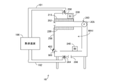
- FIG. 1 is a diagram showing a schematic configuration of a decontamination system 10 including a decontamination device 100 according to the present embodiment.
- the decontamination system 10 includes a decontamination device 100 and a safety cabinet 200.
- the decontamination device 100 is connected to the safety cabinet 200 via the pipes 101 and 102.
- the decontamination device 100 decontaminates, for example, at least one of the microorganisms and viruses present inside the safety cabinet 200.
- the decontamination device 100 is arranged outside the safety cabinet 200 to be decontaminated.
- the safety cabinet 200 is a box-shaped experimental facility for suppressing biohazard.
- the experimenter inserts his hand into the work area WA1 and conducts an experiment using, for example, a biological material.
- the safety cabinet 200 includes a fan 205, HEPA (High Efficiency Particulate Air) filters 210 and 220, and a shutter 250.
- the fan 205 operates to generate an air flow, and the clean air is discharged to the outside through the HEPA filter 210, and the clean air is supplied to the work area WA1 through the HEPA filter 220.
- the shutter 250 is configured to be openable and closable.
- the safety cabinet 200 is formed with, for example, communication holes 262,264,266,268.
- the communication hole may be installed exclusively for decontamination, or for example, a drain portion, a vacuum, and a DOP sampling port provided in a general safety cabinet may be used as the communication hole.
- Each of the communication holes 262,264,266,268 can be opened and closed.
- the decontamination device 100 is connected to the communication hole 264 via the pipe 102, and the decontamination device 100 is connected to the communication hole 268 via the pipe 101. That is, the decontamination device 100 is connected to the communication hole 268 in the ceiling of the safety cabinet 200 and the communication hole 264 in the bottom of the safety cabinet 200.
- the communication holes connecting the pipes 102 may be one or two or more.
- the shutter 250 is closed. Even when the shutter 250 is closed, the inside and the outside of the safety cabinet 200 may not be completely cut off, and in such a case, a slight gap is formed. During decontamination, the gap is cured by the curing tape 400 in order to prevent the decontamination gas from leaking, depending on the degree of the decontamination gas leak. Further, it is preferable that each of the communication holes 262 and 266 is closed.
- a BI (Biological Indicator) 230 is arranged in the space above the HEPA filter 210. Further, BI 240 is arranged in the work area WA1. After the completion of decontamination, BI230 and 240 are cultured, and the decontamination effect is confirmed based on the death status of BI230 and 240.
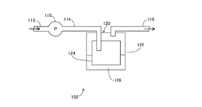
- FIG. 2 is a diagram showing a schematic configuration of the decontamination device 100.
- the decontamination device 100 includes a pump 110 and a steam generator 120. Pipes 112 and 114 are connected to the pump 110.
- the tube 112 is connected to the tube 101.
- the pump 110 is configured to suck air from the pipe 112 side and supply air to the pipe 114 side.
- the steam generating unit 120 is configured to generate only steam containing peracetic acid without heating the chemical solution 126 and without releasing mist.
- the vapor generating unit 120 includes a container 122, a moisture absorbing member 124, and a chemical solution 126.
- the container 122 is, for example, a cylindrical closed container.
- the container 122 contains the hygroscopic member 124 and the chemical solution 126.
- the chemical solution 126 is a liquid drug containing peracetic acid. That is, the drug solution 126 is a peracetic acid preparation.
- the moisture absorbing member 124 is made of, for example, a porous material. The moisture absorbing member 124 is immersed in the chemical solution 126.
- the moisture absorbing member 124 sucks up the chemical solution 126 in the container 122 by the capillary phenomenon. That is, the hygroscopic member 124 is impregnated with the chemical solution 126.
- the position and length of the communication pipes (tubes 114, 116) communicating with the closed container (container 122) in the closed container are not particularly limited. However, since it is preferable that the communication pipe enters the chemical solution 126 and the chemical solution 126 does not foam, the position and length of the communication pipe in the closed container can realize such a thing (the tip of the communication pipe is inside the chemical solution 126). It is preferable that it does not enter.
- the tip of the communication pipe (pipe 114) for introducing air and the tip of the communication pipe (pipe 116) for exhausting air are separated from each other, the air flow path is long, and the peracetic acid vapor of the moisture absorbing member 124 is generated. It is preferable that the tips of the tubes 114 and 116 are present at the positions to be promoted.
- the structure and members of the moisture absorbing member 124 are not particularly limited as long as they are moistened with the chemical solution 126 and the chemical solution 126 can be efficiently gasified (vaporized) by ventilation.
- the moisture absorbing member 124 may be a sheet-like material such as a woven fabric, a knitted fabric, a non-woven fabric, or a film as it is, or may be formed by processing it into a fold-folded shape or a corrugated shape.
- a porous material such as silica gel or zeolite may be encapsulated in a woven fabric, a knitted fabric, a non-woven fabric, a film or the like.
- the decontamination device 100 since the chemical solution 126 is not heated, it is possible to suppress the decomposition of peracetic acid and efficiently generate peracetic acid vapor. Further, according to the decontamination apparatus 100, the temperature of the chemical solution 126 containing peracetic acid is maintained at the same level as the temperature in the space in which the HEPA filters 210 and 220 to be decontaminated are arranged. The possibility of dew condensation can be suppressed.
- Air is supplied from the pump 110 via the pipe 114, and the vaporization of the chemical solution 126 that has soaked into the moisture absorbing member 124 is promoted. As a result, vapor containing peracetic acid (hereinafter, also referred to as "peracetic acid vapor") is generated.
- the peracetic acid vapor is supplied to the inside of the safety cabinet 200 via the pipe 116.
- the pipe 116 is connected to the pipe 102.
- the inside of the safety cabinet 200 is decontaminated by the peracetic acid steam.
- the HEPA filters 210 and 220 are also decontaminated through the decontamination in the safety cabinet 200.
- decontamination is performed by the peracetic acid vapor instead of the mist containing peracetic acid in the decontamination system 10 will be described below. That is, the reason why the vaporization type (steam) is used instead of the atomization type (mist) will be described.
- the HEPA filters 210 and 220 are decontaminated with a mist containing peracetic acid, the mist is collected by the HEPA filters 210 and 220.
- the pressure loss may be improved by getting wet with the collected mist, or the deterioration may be accelerated by the decontaminating agent.
- the peracetic acid vapor generated by the vaporization method is not collected as particles by the HEPA filters 210 and 220. Therefore, the problem in the atomization formula does not occur. For this reason, the vaporization type is adopted in the decontamination system 10.
- the pump 110 is configured to suck air containing peracetic acid vapor from the exhaust side of the HEPA filter 210 and supply air containing peracetic acid vapor to the air supply side of the HEPA filter 210.
- the amount of air sucked by the pump 110 from the exhaust side of the HEPA filter 210 is larger than the amount of air supplied by the pump 110 to the air supply side of the HEPA filter 210. This is achieved, for example, by leaking some air in the tube 102. Since the leaked air contains a decontamination gas, it is preferable to discharge the decontamination gas to the outside after adsorbing it with a chemical filter such as activated carbon.
- the leak location may be not only the pipe 102 but also the pump of the pipe 114 or the pipe 116.
- the inside of the safety cabinet 200 is in a negative pressure state during decontamination. As a result, it is possible to prevent the peracetic acid vapor from leaking to the outside of the safety cabinet 200.
- the inside of the safety cabinet 200 When the inside of the safety cabinet 200 is in a negative pressure state, it is preferable not to make the negative pressure too high. If the negative pressure becomes too high, a dent on the side wall of the safety cabinet 200 may be generated.
- the communication holes such as the communication holes 262 and 266 may be opened, or as shown in FIG. 3, the gap may be the lower part of the shutter 250, and the tube 300 is arranged in the gap of the shutter 250. You may. Even during decontamination, the openings allow the inside and outside of the safety cabinet 200 to communicate with each other.
- the inner diameter of each of the tube 300 and the communication hole is, for example, 1 mm to 3 cm. Further, during decontamination, the gaps under the shutter 250 except for the tube 300 are cured by the curing tape 400.
- an opening is provided in the safety cabinet 200 at the time of decontamination, and air is taken into the inside of the safety cabinet 200 through the opening, so that the inside of the safety cabinet 200 does not become too negative pressure.
- a part of the pipes 114, 116, 102 on the exhaust side of the pump 110 is provided with an openable / closable opening for discharging air circulating inside the safety cabinet 200, the decontamination device 100, and the pipes 101, 102. Can be done. If the humidity inside the safety cabinet 200 becomes too high, the air circulating inside the safety cabinet 200 is discharged from the opening, and the safety cabinet 200 is discharged through the tube 300 and the open communication holes 262 and 266 (openings). It is possible to increase the amount of air taken into the inside of the safety cabinet 200 and reduce the humidity in the safety cabinet 200. It is preferable that the released air is discharged after the decontamination gas is recovered by a chemical filter or the like.
- the humid air can be used in the tube 300 or the open communication hole 2622. Since it is introduced inside the safety cabinet 200 via 266, the humidity inside the safety cabinet 200 can be increased. This is effective when the humidity of the air outside the safety cabinet 200 is low and the humidity inside the safety cabinet 200 is too low. That is, the humidity in the safety cabinet 200 can be controlled by using the opening of the tube 300 or the open communication holes 262,266. As the amount of air introduced into the safety cabinet 200 through the opening of the tube 300 or the open communication holes 262,266 increases, the concentration of the peracetic acid vapor decreases. Therefore, the amount of air introduced into the safety cabinet 200 through the tube 300 or the open communication holes 262,266 is, for example, 3% or less of the amount of air circulating in the decontamination system 10. Is preferable.
- the fan 205 is stopped during decontamination. This is because when the fan 205 operates and generates heat, the temperature of the air in the safety cabinet 200 rises, which causes dew condensation.
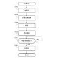
- FIG. 5 is a flowchart showing an example of the decontamination procedure in the safety cabinet 200. Each step shown in this flowchart is performed by an operator.
- the operator arranges the BI 230 and 240 in the safety cabinet 200 (step S100).
- the operator connects the decontamination device 100 to the safety cabinet 200 by using the pipes 101 and 102 (step S110).
- the operator provides an opening in the safety cabinet 200 as needed, and cures the gap with the curing tape 400 (step S120).
- the operator activates the decontamination device 100 to start decontamination in the safety cabinet 200 (step S130).
- step S140 The worker determines whether or not the predetermined time has elapsed.
- the worker waits until a predetermined time elapses (NO in step S140).
- the operator confirms the decontamination effect based on the dead state of BI 230 and 240 (step S150). Decontamination in the safety cabinet 200 is completed by confirming the death of BI 230 and 240.
- the peracetic acid vapor is sucked from the exhaust side of the HEPA filter 210, and the peracetic acid vapor is supplied to the air supply side of the HEPA filter 210. Therefore, according to the decontamination apparatus 100, the peracetic acid vapor surely passes through the HEPA filter 210, so that the occurrence of a situation in which the HEPA filter 210 is not decontaminated even though the decontamination is performed is suppressed. be able to.
- the humidity inside the safety cabinet 200 rises because the aqueous solution containing peracetic acid is vaporized. If the temperature inside the safety cabinet 200 rises during decontamination, the temperature difference between the inside and the outside of the safety cabinet 200 becomes large, and dew condensation may occur inside the safety cabinet 200.
- the temperature of the pump 110 included in the decontamination device 100 rises. Therefore, if the pump 110 is arranged inside the safety cabinet 200, the temperature inside the safety cabinet 200 rises, and dew condensation may occur inside the safety cabinet 200.
- the decontamination device 100 is used in a state of being arranged outside the safety cabinet 200. Therefore, according to the decontamination device 100, the temperature of the pump 110 has almost no effect on the temperature inside the safety cabinet 200, so that the possibility of dew condensation inside the safety cabinet 200 can be reduced.
- the particle removing filters arranged in the safety cabinet 200 are HEPA filters 210 and 220.
- the particle removing filter arranged in the safety cabinet 200 is not limited to this.
- the particle removal filter to be decontaminated may be, for example, a medium performance filter or a ULPA filter.
- the decontamination target was the safety cabinet 200.
- the decontamination target is not limited to this.
- the decontamination target may be any container as long as it can accommodate the particle removing filter inside.
- the decontamination target may be hermetically sealed or may be in a semi-enclosed state.
- the semi-sealed state is a state in which the seal is close to the seal but cannot be completely sealed.
- the air between the inside and the outside of the safety cabinet 200 is blocked at a certain level, and the concentration of the peracetic acid vapor does not decrease extremely due to the leakage of the peracetic acid vapor.
- the decontamination target may be an isolator device, an incubator, a centrifuge, a pass box, a storage, an air conditioner, a clean bench, a duct, or the like.
- the air flow is in the order of the safety cabinet 200, the pump 110, the steam generator 120, and the safety cabinet 200, but the order of air flow is not limited to this.
- air may flow in the order of the safety cabinet 200, the steam generator 120, the pump 110, and the safety cabinet 200.
- the structure of the steam generating unit 120 may be a structure that generates peracetic acid vapor without generating mist.
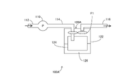
- a stirring fan F1 for promoting steaming may be installed in the steam generating unit 120A, and if the steaming is sufficient, the porous body 124 may be omitted. ..
- the structure of the steam generating unit 120 may be as shown in FIG. 7. That is, in the vapor generating section 120B, the moisture absorbing member 124B sucks up the chemical solution 126B by the capillary phenomenon.
- the peracetic acid steam (gas) is flowed to the pipe 116B side by the air introduced into the steam generator 120B through the pipe 114B.
- the peracetic acid vapor is introduced into the safety cabinet 200 via the tube 116B.
- the pump 110 may be capable of sucking and exhausting air and having the ability to circulate air for the present invention, eg, centrifugal blowers, axial blowers, mixed flow blowers, cross flow blowers, diaphragm pumps, pistons.
- air for the present invention eg, centrifugal blowers, axial blowers, mixed flow blowers, cross flow blowers, diaphragm pumps, pistons.
- the decontamination system 10 shown in FIG. 1 was prepared.
- MHE-181AB3 manufactured by PHC Corporation was used and installed in a place where the wind of the air conditioner in the room did not directly hit.
- chemical solution 126 (FIG. 2), Mincare manufactured by Cantel Co., Ltd. was used.
- BI 230 and 240 HMV-091 bacterial count 106 manufactured by MesaLab was used.
- culture medium of BI230 and 240 PM / 100 manufactured by MesaLab was used.
- a thermo-hygrometer for measuring the temperature and humidity in the safety cabinet 200 a temperature-humidity logger LR5001 manufactured by Hioki Co., Ltd. was used.
- the decontamination device 100 and the safety cabinet 200 were connected using pipes 101 and 102 so as to suck air from the downstream side of the HEPA filter 210 and supply air into the safety cabinet 200 from the drain portion.
- the safety cabinet 200 was cured, the communication holes 262 and 266 were closed, and the inside of the safety cabinet 200 was placed in a semi-sealed state.
- a tube 300 was attached to the gap of the safety cabinet 200.
- the pump 110 was operated with the pressure gauge attached to the tube 300.
- the needle of the pressure gauge advanced toward the negative pressure.
- a flow meter was attached to the tube 300 to measure the flow rate. The flow rate was 5 ml / min.
- Mincare peracetic acid content 4.5%) diluted with pure water was used as the chemical solution 126.
- the dilution ratio was 10%.
- As the container 122 a cylindrical closed container having an inner diameter of about 200 mm and a height of about 300 mm was used. The container 122 was filled with 1 L of the chemical solution 126. Further, the cylindrical moisture absorbing member 124 was arranged along the inner circumference of the container 122.
- BI230 and 240 were arranged above the HEPA filter 210 and in the work area WA1, respectively. After decontamination, BI230 and 240 were cultured.
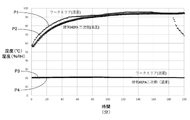
- FIG. 8 is a diagram summarizing the values of the thermo-hygrometer at the time of decontamination.
- each point P1 indicates the humidity in the work area WA1 and each point P2 indicates the humidity above the HEPA filter 210.
- Each point P3 indicates the temperature in the work area WA1, and each point P4 indicates the temperature above the HEPA filter 210. In this experiment, no dew condensation occurred in the safety cabinet 200.
- BI230 and 240 were cultured. BI230 and 240 were all dead (negative). Further, since the pump 110 was arranged outside the safety cabinet 200, no temperature rise was observed inside the safety cabinet 200.
Landscapes
- Health & Medical Sciences (AREA)
- Epidemiology (AREA)
- Life Sciences & Earth Sciences (AREA)
- Animal Behavior & Ethology (AREA)
- General Health & Medical Sciences (AREA)
- Public Health (AREA)
- Veterinary Medicine (AREA)
- Chemical & Material Sciences (AREA)
- Chemical Kinetics & Catalysis (AREA)
- General Chemical & Material Sciences (AREA)
- Apparatus For Disinfection Or Sterilisation (AREA)
Abstract
除染装置は、除染対象の内部に存在する微生物及びウイルスの少なくとも一方を除染するように構成されている。除染対象の内部には、粒子除去用フィルタが取り付けられている。除染装置は、蒸気発生部と、ポンプとを備えている。蒸気発生部は、加熱を伴なうことなく、かつ、ミストを放出することなく、過酢酸を含む蒸気を発生させるように構成されている。ポンプは、粒子除去用フィルタの排気側から上記蒸気を吸引すると共に、粒子除去用フィルタの給気側へ上記蒸気を供給するように構成されている。この除染装置は、除染対象の外部に配置された状態で使用される。
Description
本発明は、除染装置及び除染方法に関する。
特許第6250491号公報(特許文献1)は、バイオセーフティキャビネットの内部を除染するように構成された除染装置を開示する。この除染装置においては、過酢酸を含むミストを用いることによって、バイオセーフティキャビネットの内部の除染が行なわれる(特許文献1参照)。
除染対象の内部に粒子除去用フィルタ(HEPA(High Efficiency Particulate Air)フィルタ等)が存在する場合がある。除染対象としては、例えば、安全キャビネット、培養器、アイソレーター及び自動培養装置が挙げられる。この場合に、除染対象の内部の除染を通じて、粒子除去用フィルタの除染が行なわれる。特許文献1に開示されている除染装置のように過酢酸を含むミストによって粒子除去用フィルタの除染が行なわれると、除染環境中の相対湿度が低い場合にはミストが速やかに蒸気となるが、特に相対湿度が80%を超える場合にはミストの蒸発速度が低下し、ミストが蒸発しきれずにミストのまま浮遊することになる。その結果、ミストが粒子除去用フィルタに捕集される。そして、粒子除去用フィルタに液滴が付着して粒子除去用フィルタが濡れると、圧力損失が上昇し得る。
本発明者(ら)は、このような問題を考慮し、過酢酸を含むミストではなく、過酢酸を含む蒸気によって粒子除去用フィルタの除染を行なうことを考えた。しかしながら、過酢酸の比重が大きいため、除染対象の内部に供給された蒸気は、除染対象の内部において底部に溜まりやすい。一方、例えば、安全キャビネットにおいて、粒子除去用フィルタは、天井付近に配置されている場合が多い。このような場合に、除染対象の内部に過酢酸を含む蒸気を供給したとしても、蒸気が粒子除去用フィルタを通過しないため、粒子除去用フィルタが十分に除染されないという事態が生じ得る。
本発明は、このような問題を解決するためになされたものであって、その目的は、除染を行なったにもかかわらず、粒子除去用フィルタが除染されていないという事態の発生を抑制可能な除染装置及び除染方法を提供することである。
本発明のある局面に従う除染装置は、除染対象の内部に存在する微生物及びウイルスの少なくとも一方を除染するように構成されている。除染対象の内部には、粒子除去用フィルタが取り付けられている。除染装置は、蒸気発生部と、ポンプとを備えている。蒸気発生部は、加熱を伴うことなく、かつ、ミストを放出することなく、過酢酸を含む蒸気を発生させるように構成されている。ポンプは、粒子除去用フィルタの排気側から上記蒸気を吸引すると共に、粒子除去用フィルタの給気側へ上記蒸気を供給するように構成されている。この除染装置は、除染対象の外部に配置された状態で使用される。
この除染装置においては、粒子除去用フィルタの排気側から過酢酸を含む蒸気が吸引されると共に、粒子除去用フィルタの給気側へ該蒸気が供給される。したがって、この除染装置によれば、過酢酸を含む蒸気が確実に粒子除去用フィルタを通過するため、除染を行なったにもかかわらず、粒子除去用フィルタが除染されていないという事態の発生を抑制することができる。
また、除染中は、蒸気が発生するため、除染対象の内部の湿度が上がる。仮に除染中に除染対象の内部の温度が上がると、除染対象の内部と外部との間の温度差が大きくなり、除染対象の内部で結露が生じ得る。除染中は除染装置に含まれるポンプの温度が上がる。したがって、仮に除染装置(ポンプ)が除染対象の内部に配置される場合には、除染対象の内部の温度が上がり、除染対象の内部で結露が生じ得る。本発明に従う除染装置は、除染対象の外部に配置された状態で使用される。したがって、この除染装置によれば、ポンプの温度が除染対象の内部の温度にほとんど影響を与えないため、除染対象の内部で結露が生じる可能性を低減することができる。
上記除染装置において、ポンプが粒子除去用フィルタの排気側から吸引する空気量は、ポンプが粒子除去用フィルタの給気側へ供給する空気量よりも多くてもよい。
これにより、除染対象の内部は陰圧状態となる。したがって、この除染装置によれば、除染対象の内部に供給された蒸気が除染対象の外部に漏れにくくすることができる。
また、本発明の他の局面に従う除染方法は、上記除染装置を用いることによって、微生物及びウイルスの少なくとも一方を除染する方法である。この除染方法は、粒子除去用フィルタの排気側にBI(Biological Indicator)を配置するステップと、除染後のBIの死滅状況に基づいて除染効果を確認するステップとを含む。
この除染方法によれば、BIの死滅状況に基づいて、粒子除去用フィルタにおける除染効果を確認することができる。
また、本発明の他の局面に従う除染方法は、上記除染装置を用いることによって、微生物及びウイルスの少なくとも一方を除染する方法である。除染対象においては、除染対象の内部と外部とを連通させる隙間が形成されている場合がある。この除染方法は、除染対象において上記隙間が形成されている場合に隙間を養生するステップと、粒子除去用フィルタの排気側から上記蒸気を吸引すると共に、粒子除去用フィルタの給気側へ上記蒸気を供給することによって、上記蒸気を循環させるステップとを含む。
この除染方法によれば、除染対象における隙間が養生されるため、除染中に除染対象の内部を陰圧状態にすることができる。その結果、この除染方法によれば、除染対象の内部に供給された蒸気が除染対象の外部に漏れにくくすることができる。
本発明によれば、除染を行なったにもかかわらず、粒子除去用フィルタが除染されていないという事態の発生を抑制可能な除染装置及び除染方法を提供することができる。
以下、本発明の実施の形態について、図面を参照しながら詳細に説明する。なお、図中同一又は相当部分には同一符号を付してその説明は繰り返さない。
[1.除染システムの構成]
図1は、本実施の形態に従う除染装置100を含む除染システム10の概略構成を示す図である。図1に示されるように、除染システム10は、除染装置100と、安全キャビネット200とを含んでいる。除染システム10においては、管101,102を介して除染装置100が安全キャビネット200に接続されている。除染装置100によって、例えば、安全キャビネット200の内部に存在する微生物及びウイルスの少なくとも一方が除染される。なお、除染システム10において、除染装置100は、除染対象である安全キャビネット200の外部に配置されている。
図1は、本実施の形態に従う除染装置100を含む除染システム10の概略構成を示す図である。図1に示されるように、除染システム10は、除染装置100と、安全キャビネット200とを含んでいる。除染システム10においては、管101,102を介して除染装置100が安全キャビネット200に接続されている。除染装置100によって、例えば、安全キャビネット200の内部に存在する微生物及びウイルスの少なくとも一方が除染される。なお、除染システム10において、除染装置100は、除染対象である安全キャビネット200の外部に配置されている。
安全キャビネット200は、バイオハザードを抑制するための箱状の実験設備である。実験者は、ワークエリアWA1に手を挿入し、たとえば生物材料を用いた実験を行なう。安全キャビネット200は、ファン205と、HEPA(High Efficiency Particulate Air)フィルタ210,220と、シャッタ250とを含んでいる。実験時には、ファン205が作動することによって気流が生じ、HEPAフィルタ210を通じて清浄な空気が外部に排出されると共に、HEPAフィルタ220を通じて清浄な空気がワークエリアWA1に供給される。シャッタ250は、開閉可能に構成されている。
安全キャビネット200には、例えば、連通孔262,264,266,268が形成されている。連通孔は除染専用に設置されたものであってもよいし、例えば、一般的な安全キャビネットに設けられているドレーン部、バキューム及びDOPサンプリングポートが連通孔として用いられてもよい。連通孔262,264,266,268の各々は、開閉可能になっている。図1の例では、管102を介して連通孔264に除染装置100が接続されており、管101を介して連通孔268に除染装置100が接続されている。すなわち、安全キャビネット200の天井部の連通孔268と、安全キャビネット200の底部の連通孔264とに除染装置100が接続されている。管102を接続する連通孔は、1つであってもよく、2つ以上であってもよい。
除染中は、シャッタ250が閉められる。シャッタ250が閉められた状態であっても、安全キャビネット200の内部と外部との間は完全には遮断されない場合があり、そのような場合には僅かな隙間が形成される。除染中において、上記隙間は、除染ガスの漏れの程度によっては、除染ガスの漏れを防ぐために、養生テープ400によって養生される。また、連通孔262,266の各々は閉鎖されることが好ましい。
また、除染に先立って、HEPAフィルタ210の上方の空間には、BI(Biological Indicator)230が配置される。また、ワークエリアWA1には、BI240が配置される。除染の終了後に、BI230,240の培養を行い、BI230,240の死滅状況に基づいて、除染効果が確認される。
図2は、除染装置100の概略構成を示す図である。図2に示されるように、除染装置100は、ポンプ110と、蒸気発生部120とを含んでいる。ポンプ110には、管112,114が接続されている。管112は、管101に接続されている。ポンプ110は、管112側から空気を吸引し、管114側に空気を供給するように構成されている。
蒸気発生部120は、薬液126を加熱することなく、かつ、ミストを放出することなく、過酢酸を含む蒸気のみを発生させるように構成されている。蒸気発生部120は、容器122と、吸湿部材124と、薬液126とを含んでいる。容器122は、例えば筒状の密閉容器である。容器122には、吸湿部材124と、薬液126とが収容されている。薬液126は、過酢酸を含む液体状の薬剤である。すなわち、薬液126は、過酢酸製剤である。吸湿部材124は、例えば、多孔質材料によって構成されている。吸湿部材124は、薬液126に浸漬されている。吸湿部材124は、毛細管現象により容器122内の薬液126を吸い上げる。すなわち、吸湿部材124には、薬液126が染み込んでいる。密閉容器(容器122)に連通する連通管(管114,116)の密閉容器内での位置及び長さは特に限定されない。但し、連通管が薬液126内に入り薬液126が泡立たない方が好ましいため、連通管の密閉容器内での位置及び長さはそのようなことを実現できるもの(連通管の先端が薬液126内に入らない)であることが好ましい。また、エアを導入する連通管(管114)の先端とエアを排気する連通管(管116)の先端とが離れており、エアの流路が長く、吸湿部材124の過酢酸蒸気の発生を促進する位置に管114,116の先端が存在することが好ましい。
なお、吸湿部材124は、薬液126により湿潤し、通風により薬液126を効率良くガス化(気化)できれば、構造や部材は特に限定されない。例えば、吸湿部材124は、織物、編み物、不織布又はフィルム等のシート状のものをそのまま使用してもよく、ひだ折り状、コルゲート状に加工することによって形成されていてもよい。シリカゲル、ゼオライト等の多孔質材料が織物、編み物、不織布又はフィルム等の中に内包されていてもよい。
除染装置100によれば、薬液126が加熱されないため、過酢酸の分解を抑制して効率良く過酢酸蒸気を発生させることができる。また、この除染装置100によれば、過酢酸を含む薬液126の温度が除染対象のHEPAフィルタ210,220が配置された空間内の温度と同程度に維持されるため、該空間内で結露が発生する可能性を抑制することができる。
管114を介してポンプ110から空気の供給を受け、吸湿部材124に染み込んでいる薬液126の気化が促進される。これにより、過酢酸を含む蒸気(以下、「過酢酸蒸気」とも称する。)が発生する。過酢酸蒸気は、管116を介して安全キャビネット200の内部に供給される。なお、管116は、管102に接続されている。
このように、除染システム10においては、過酢酸蒸気によって安全キャビネット200の内部が除染される。安全キャビネット200内の除染を通じて、HEPAフィルタ210,220も除染される。除染システム10において、過酢酸を含むミストではなく、過酢酸蒸気によって除染が行なわれる理由について次に説明する。すなわち、霧化式(ミスト)ではなく、気化式(蒸気)が用いられている理由について説明する。
過酢酸を含むミストによってHEPAフィルタ210,220の除染が行なわれると、ミストがHEPAフィルタ210,220に捕集される。その結果、HEPAフィルタ210,220においては、捕集したミストによって濡れることにより圧力損失が向上したり、除染薬によって劣化が促進する可能性がある。
気化式で発生させた過酢酸蒸気は、粒子としてHEPAフィルタ210,220に捕集されない。したがって、上記霧化式における問題が生じない。このような理由により、除染システム10においては、気化式が採用されている。
ポンプ110は、HEPAフィルタ210の排気側から過酢酸蒸気を含む空気を吸引すると共に、HEPAフィルタ210の給気側へ過酢酸蒸気を含む空気を供給するように構成されている。なお、ポンプ110がHEPAフィルタ210の排気側から吸引する空気量は、ポンプ110がHEPAフィルタ210の給気側へ供給する空気量よりも多い。これは、例えば、管102において一部の空気をリークさせることによって実現される。リークさせたエアには除染ガスが含まれているため、除染ガスを活性炭等のケミカルフィルタで吸着した後のエアを外部に放出することが好ましい。但し、リークさせる箇所は管102だけでなく、管114や管116のポンプでもよい。
ポンプ110において吸引する空気量が供給する空気量よりも多いため、除染中に安全キャビネット200の内部は陰圧状態となる。これにより、過酢酸蒸気が安全キャビネット200の外部に漏れ出ることを抑制することができる。
安全キャビネット200内を陰圧状態にする場合、陰圧の圧力を高くしすぎないことが好ましい。陰圧が高くなりすぎると、安全キャビネット200の側壁の凹みなどを発生させる恐れがある。
減圧になりすぎないようにするために、安全キャビネット200において開口を設けることが好ましい。例えば、連通孔262,266のような連通孔を開放してもよいし、図3に示されるように、シャッタ250の下部の隙間であっても良く、シャッタ250の隙間にチューブ300を配置してもよい。除染中であっても、開口は、安全キャビネット200の内部と外部とを連通させる。なお、チューブ300及び連通孔の各々の内径は、例えば、1mm~3cmである。さらに、除染中において、シャッタ250の下部のチューブ300を除く隙間は養生テープ400によって養生される。
なお、除染システム10においては、除染時に安全キャビネット200に開口が設けられ、開口を介して安全キャビネット200の内部に空気が取り込まれるため、安全キャビネット200の内部が陰圧になりすぎない。
また、十分な除染効果を得るためには、安全キャビネット200内の湿度をある程度高く維持する必要がある。一方、安全キャビネット200内の湿度が高くなりすぎると、安全キャビネット200内で結露が生じる。結露は、安全キャビネット200内の部品の腐食の原因になる。除染システム10においては、チューブ300や解放している連通孔262,266(開口)を介して安全キャビネット200の内部に空気が取り込まれるため、安全キャビネット200内の湿度が必要以上に高くならない。
また、例えば、ポンプ110の排気側の管114,116,102の一部分に、安全キャビネット200、除染装置100及び管101,102の内部を循環するエアを放出する開閉可能な開口部を設けることができる。安全キャビネット200内の湿度が高くなりすぎた場合には、内部を循環するエアを該開口部から放出して、チューブ300や解放している連通孔262、266(開口)を介して安全キャビネット200の内部に取り込まれる空気の量を増やして安全キャビネット200内の湿度を下げることが可能である。放出されたエアはケミカルフィルタ等で除染ガスが回収されてから放出されることが好ましい。
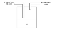
また、例えば、チューブ300又は解放している連通孔262,266に図4に示されるような水が入ったタンクを配置すれば、湿度の高い空気がチューブ300又は解放している連通孔262,266を介して安全キャビネット200の内部に導入されるため、安全キャビネット200内の湿度を上昇させることができる。これは、安全キャビネット200の外部の空気の湿度が低く、安全キャビネット200の内部の湿度が低くなりすぎたときに有効である。すなわち、チューブ300又は解放している連通孔262,266の開口を用いることによって、安全キャビネット200内の湿度をコントロールすることができる。なお、チューブ300又は解放している連通孔262,266の開口を介して安全キャビネット200の内部に導入される空気が多くなると、過酢酸蒸気の濃度が薄くなる。したがって、チューブ300又は解放している連通孔262,266を介して安全キャビネット200の内部に導入される空気の量は、例えば、除染システム10内を循環する空気量の3%以下であることが好ましい。
また、除染中において、ファン205は停止していることが好ましい。ファン205が作動し発熱すると、安全キャビネット200内の空気の温度が上昇し、結露発生の原因になるためである。
[2.除染手順]
図5は、安全キャビネット200内の除染手順の一例を示すフローチャートである。このフローチャートに示される各工程は、作業者によって行なわれる。
図5は、安全キャビネット200内の除染手順の一例を示すフローチャートである。このフローチャートに示される各工程は、作業者によって行なわれる。
図5を参照して、作業者は、安全キャビネット200内に、BI230,240を配置する(ステップS100)。作業者は、管101,102を用いて、安全キャビネット200に除染装置100を接続する(ステップS110)。作業者は、必要に応じて安全キャビネット200に開口を設けたり、隙間を養生テープ400によって養生する(ステップS120)。作業者は、除染装置100を作動させ、安全キャビネット200内の除染を開始させる(ステップS130)。
作業者は、所定時間が経過したか否かを判断する(ステップS140)。作業者は、所定時間が経過するまで待機する(ステップS140においてNO)。所定時間が経過すると(ステップS140においてYES)、作業者は、BI230,240の死滅状態に基づいて除染効果を確認する(ステップS150)。BI230,240の死滅が確認されることによって、安全キャビネット200内の除染が完了する。
[3.特徴]
以上のように、除染装置100においては、HEPAフィルタ210の排気側から過酢酸を含む蒸気が吸引されると共に、HEPAフィルタ210の給気側へ該蒸気が供給される。仮に過酢酸蒸気の吸引が行なわれなかったとすると、過酢酸の比重が大きいため、安全キャビネット200の内部に供給された過酢酸蒸気は、安全キャビネット200の内部において底部に溜まりやすい。過酢酸蒸気が安全キャビネット200の底部に溜まると、過酢酸蒸気がHEPAフィルタ210を通過しないため、HEPAフィルタ210が十分に除染されないという事態が生じ得る。
以上のように、除染装置100においては、HEPAフィルタ210の排気側から過酢酸を含む蒸気が吸引されると共に、HEPAフィルタ210の給気側へ該蒸気が供給される。仮に過酢酸蒸気の吸引が行なわれなかったとすると、過酢酸の比重が大きいため、安全キャビネット200の内部に供給された過酢酸蒸気は、安全キャビネット200の内部において底部に溜まりやすい。過酢酸蒸気が安全キャビネット200の底部に溜まると、過酢酸蒸気がHEPAフィルタ210を通過しないため、HEPAフィルタ210が十分に除染されないという事態が生じ得る。
上述のように、除染装置100においては、HEPAフィルタ210の排気側から過酢酸蒸気が吸引されると共に、HEPAフィルタ210の給気側へ過酢酸蒸気が供給される。したがって、除染装置100によれば、過酢酸蒸気が確実にHEPAフィルタ210を通過するため、除染を行なったにもかかわらず、HEPAフィルタ210が除染されていないという事態の発生を抑制することができる。
また、除染中は、過酢酸を含む水溶液を気化させるため、安全キャビネット200の内部の湿度が上がる。仮に除染中に安全キャビネット200の内部の温度が上がると、安全キャビネット200の内部と外部との間の温度差が大きくなり、安全キャビネット200の内部で結露が生じ得る。除染中は除染装置100に含まれるポンプ110の温度が上がる。したがって、仮にポンプ110が安全キャビネット200の内部に配置される場合には、安全キャビネット200の内部の温度が上がり、安全キャビネット200の内部で結露が生じ得る。これに対して、除染装置100は、安全キャビネット200の外部に配置された状態で使用される。したがって、除染装置100によれば、ポンプ110の温度が安全キャビネット200の内部の温度にほとんど影響を与えないため、安全キャビネット200の内部で結露が生じる可能性を低減することができる。
[4.変形例]
以上、実施の形態について説明したが、本発明は、上記実施の形態に限定されるものではなく、その趣旨を逸脱しない限りにおいて、種々の変更が可能である。以下、変形例について説明する。
以上、実施の形態について説明したが、本発明は、上記実施の形態に限定されるものではなく、その趣旨を逸脱しない限りにおいて、種々の変更が可能である。以下、変形例について説明する。
<4-1>
上記実施の形態において、安全キャビネット200内に配置される粒子除去用フィルタは、HEPAフィルタ210,220であった。しかしながら、安全キャビネット200内に配置される粒子除去用フィルタは、これに限定されない。除染対象の粒子除去用フィルタは、たとえば、中性能フィルタであってもよいし、ULPAフィルタであってもよい。
上記実施の形態において、安全キャビネット200内に配置される粒子除去用フィルタは、HEPAフィルタ210,220であった。しかしながら、安全キャビネット200内に配置される粒子除去用フィルタは、これに限定されない。除染対象の粒子除去用フィルタは、たとえば、中性能フィルタであってもよいし、ULPAフィルタであってもよい。
<4-2>
また、上記実施の形態において、除染対象は、安全キャビネット200であった。しかしながら、除染対象はこれに限定されない。たとえば、除染対象は、粒子除去用フィルタを内部に収容可能な容器であればどのような容器であってもよい。また、除染対象は、密閉されていてもよいし、準密閉状態であってもよい。準密閉状態とは、密閉に近いが完全な密閉ができてない状態をいう。例えば、安全キャビネット200の内部と外部との空気が一定レベルで遮断され、過酢酸蒸気の漏洩によって過酢酸蒸気の濃度が極端に低下しない程度の状態をいう。たとえば、除染対象は、アイソレータ装置、培養器、遠心分離機、パスボックス、保管庫、空調機器、クリーンベンチ、ダクト等であってもよい。
また、上記実施の形態において、除染対象は、安全キャビネット200であった。しかしながら、除染対象はこれに限定されない。たとえば、除染対象は、粒子除去用フィルタを内部に収容可能な容器であればどのような容器であってもよい。また、除染対象は、密閉されていてもよいし、準密閉状態であってもよい。準密閉状態とは、密閉に近いが完全な密閉ができてない状態をいう。例えば、安全キャビネット200の内部と外部との空気が一定レベルで遮断され、過酢酸蒸気の漏洩によって過酢酸蒸気の濃度が極端に低下しない程度の状態をいう。たとえば、除染対象は、アイソレータ装置、培養器、遠心分離機、パスボックス、保管庫、空調機器、クリーンベンチ、ダクト等であってもよい。
<4-3>
図2に示される除染装置100は、エアの流れが安全キャビネット200、ポンプ110、蒸気発生部120、安全キャビネット200という順であったが、エアの流れる順序はこれに限定されない。例えば、安全キャビネット200、蒸気発生部120、ポンプ110、安全キャビネット200という順でエアが流れてもよい。
図2に示される除染装置100は、エアの流れが安全キャビネット200、ポンプ110、蒸気発生部120、安全キャビネット200という順であったが、エアの流れる順序はこれに限定されない。例えば、安全キャビネット200、蒸気発生部120、ポンプ110、安全キャビネット200という順でエアが流れてもよい。
<4-4>
蒸気発生部120の構造は、ミストを発生させずに過酢酸蒸気を発生させる構造であればよい。例えば、図6に示されるように、蒸気発生部120A内に蒸気化を促すための攪拌ファンF1を設置してもよく、蒸気化が十分であれば、多孔質体124が省略されてもよい。また、蒸気発生部120の構造は、図7に示されるようなものであってもよい。すなわち、蒸気発生部120Bにおいては、吸湿部材124Bが薬液126Bを毛細管現象によって吸い上げる。管114Bを介して蒸気発生部120B内に導入された空気によって、過酢酸蒸気(ガス)が管116B側に流される。過酢酸蒸気は、管116Bを介して安全キャビネット200内に導入される。
蒸気発生部120の構造は、ミストを発生させずに過酢酸蒸気を発生させる構造であればよい。例えば、図6に示されるように、蒸気発生部120A内に蒸気化を促すための攪拌ファンF1を設置してもよく、蒸気化が十分であれば、多孔質体124が省略されてもよい。また、蒸気発生部120の構造は、図7に示されるようなものであってもよい。すなわち、蒸気発生部120Bにおいては、吸湿部材124Bが薬液126Bを毛細管現象によって吸い上げる。管114Bを介して蒸気発生部120B内に導入された空気によって、過酢酸蒸気(ガス)が管116B側に流される。過酢酸蒸気は、管116Bを介して安全キャビネット200内に導入される。
<4-5>
ポンプ110は、エアを吸引し、排気でき、当該発明に関してエアを循環させる能力があればよく、例えば、遠心式送風機、軸流式送風機、斜流式送風機、横流式送風機、ダイヤフラム式ポンプ、ピストンポンプ、プランジャーポンプなどがあり、ポンプ110の構造及びサイズは特に限定されない。
ポンプ110は、エアを吸引し、排気でき、当該発明に関してエアを循環させる能力があればよく、例えば、遠心式送風機、軸流式送風機、斜流式送風機、横流式送風機、ダイヤフラム式ポンプ、ピストンポンプ、プランジャーポンプなどがあり、ポンプ110の構造及びサイズは特に限定されない。
[5.実験]
本発明の効果を確認するために、以下の実験を行なった。以下、実験内容及び実験結果について説明する。
本発明の効果を確認するために、以下の実験を行なった。以下、実験内容及び実験結果について説明する。
この実験においては、図1に示される除染システム10を準備した。安全キャビネット200としては、PHC株式会社製のMHE-181AB3を用い部屋の空調の風が直接当たらない場所に設置した。薬液126(図2)としては、キャンテル社製のミンケアを用いた。BI230,240としては、MesaLab社製のHMV-091 菌数106を用いた。BI230,240の培養液としては、MesaLab社製のPM/100を用いた。安全キャビネット200内の温度及び湿度を測定するための温湿度計としては、日置社製の温湿度ロガーLR5001を用いた。
HEPAフィルタ210の下流側から空気を吸引し、ドレーン部から安全キャビネット200内に空気を供給するように、管101,102を用いて除染装置100と安全キャビネット200とを接続した。安全キャビネット200の養生を行ない、連通孔262,266を閉じ、安全キャビネット200内を準密閉状態とした。安全キャビネット200の隙間には、チューブ300を取り付けた。チューブ300に圧力計を取り付けた状態で、ポンプ110を作動させた。負圧の方に圧力計の針が進んだ。また、チューブ300に流量計を取り付けて流量を測定した。流量は5ml/minであった。
ミンケア(過酢酸含有率4.5%)を純水で希釈したものを薬液126として用いた。希釈割合は10%とした。容器122としては、内径約200mm、高さ約300mmの円筒形の密閉容器を用いた。容器122には、1Lの薬液126を入れた。また、円筒形の吸湿部材124を容器122の内周に沿うように配置した。
BI230,240は、HEPAフィルタ210の上方及びワークエリアWA1内にそれぞれ配置された。除染後にBI230,240を培養した。
ポンプ110の循環流量は、120L/minであった。除染時間は、185分であった。3時間後の安全キャビネット200内の湿度はRH94%であった。
図8は、除染時の温湿度計の値をまとめた図である。図8を参照して、各点P1はワークエリアWA1における湿度を示し、各点P2はHEPAフィルタ210の上方における湿度を示す。各点P3はワークエリアWA1における温度を示し、各点P4はHEPAフィルタ210の上方における温度を示す。当該実験では安全キャビネット200内において結露は発生しなかった。
除染終了後にBI230,240を培養した。BI230,240はすべて死滅していた(陰性であった)。また、ポンプ110が安全キャビネット200の外部に配置されていたため、安全キャビネット200内において温度の上昇は見られなかった。
10 除染システム、100 除染装置、101,102,112,114,116 管、110 ポンプ、120 蒸気発生部、122 容器、124 吸湿部材、126 薬液、200 安全キャビネット、205 ファン、210,220 HEPAフィルタ、230,240 BI、250 シャッタ、262,264,266,268 連通孔、300 チューブ、400 養生テープ、P1,P2,P3,P4 点、WA1 ワークエリア。
Claims (4)
- 除染対象の内部に、粒子除去用フィルタが取り付けられており、前記除染対象の内部に存在する微生物及びウイルスの少なくとも一方を除染するように構成された除染装置であって、
加熱を伴なうことなく、かつ、ミストを放出することなく、過酢酸を含む蒸気を発生させるように構成された蒸気発生部と、
前記粒子除去用フィルタの排気側から前記蒸気を吸引すると共に、前記粒子除去用フィルタの給気側へ前記蒸気を供給するように構成されたポンプと、
を備え、
前記除染装置は、前記除染対象の外部に配置された状態で使用される、除染装置。 - 前記ポンプが前記粒子除去用フィルタの排気側から吸引する空気量は、前記ポンプが前記粒子除去用フィルタの給気側へ供給する空気量よりも多い、請求項1に記載の除染装置。
- 請求項1又は請求項2に記載の除染装置を用いることによって、微生物及びウイルスの少なくとも一方を除染する除染方法であって、
前記粒子除去用フィルタの排気側にBI(Biological Indicator)を配置するステップと、
除染後の前記BIの死滅状況に基づいて除染効果を確認するステップと、
を含む、除染方法。 - 請求項1又は請求項2に記載の除染装置を用いることによって、微生物及びウイルスの少なくとも一方を除染する除染方法であって、
前記除染対象においては、前記除染対象の内部と外部とを連通させる隙間が形成されており、
前記隙間を養生するステップと、
前記粒子除去用フィルタの排気側から前記蒸気を吸引すると共に、前記粒子除去用フィルタの給気側へ前記蒸気を供給することによって、前記蒸気を循環させるステップと、
を含む、除染方法。
Priority Applications (3)
| Application Number | Priority Date | Filing Date | Title |
|---|---|---|---|
| US18/029,744 US20230364285A1 (en) | 2020-10-02 | 2021-10-01 | Decontamination apparatus and decontamination method |
| EP21875897.7A EP4223322A4 (en) | 2020-10-02 | 2021-10-01 | DECONTAMINATION APPARATUS AND DECONTAMINATION METHOD |
| JP2022554160A JP7824880B2 (ja) | 2020-10-02 | 2021-10-01 | 除染装置及び除染方法 |
Applications Claiming Priority (2)
| Application Number | Priority Date | Filing Date | Title |
|---|---|---|---|
| JP2020-167522 | 2020-10-02 | ||
| JP2020167522 | 2020-10-02 |
Publications (1)
| Publication Number | Publication Date |
|---|---|
| WO2022071602A1 true WO2022071602A1 (ja) | 2022-04-07 |
Family
ID=80951747
Family Applications (1)
| Application Number | Title | Priority Date | Filing Date |
|---|---|---|---|
| PCT/JP2021/036526 Ceased WO2022071602A1 (ja) | 2020-10-02 | 2021-10-01 | 除染装置及び除染方法 |
Country Status (5)
| Country | Link |
|---|---|
| US (1) | US20230364285A1 (ja) |
| EP (1) | EP4223322A4 (ja) |
| JP (1) | JP7824880B2 (ja) |
| TW (1) | TWI883274B (ja) |
| WO (1) | WO2022071602A1 (ja) |
Cited By (1)
| Publication number | Priority date | Publication date | Assignee | Title |
|---|---|---|---|---|
| JP7392235B1 (ja) * | 2023-06-06 | 2023-12-06 | Sdバイオシステム株式会社 | 無菌性密閉空間内の除染装置及び当該装置を用いた除染方法 |
Citations (6)
| Publication number | Priority date | Publication date | Assignee | Title |
|---|---|---|---|---|
| US20020160440A1 (en) * | 2001-04-17 | 2002-10-31 | Mcdonnell Gerald E. | Vapor phase decontamination process biological indicator evaluator resistomer (BIER) vessel |
| JP2006271583A (ja) * | 2005-03-29 | 2006-10-12 | Hitachi Plant Technologies Ltd | ファンフィルタユニット及びクリーンルームの殺菌装置並びにその方法 |
| JP2008188043A (ja) * | 2007-01-31 | 2008-08-21 | Ihi Shibaura Machinery Corp | 殺菌ガス浸透装置 |
| JP2017205080A (ja) * | 2016-05-19 | 2017-11-24 | 澁谷工業株式会社 | アイソレータシステム |
| JP6250491B2 (ja) | 2014-07-18 | 2017-12-20 | ファーマバイオ株式会社 | 超音波除染装置 |
| JP2018517539A (ja) * | 2015-05-27 | 2018-07-05 | マー コア ピュリフィケーション,インコーポレイテッド | 低相対湿度の除染システム |
Family Cites Families (5)
| Publication number | Priority date | Publication date | Assignee | Title |
|---|---|---|---|---|
| US6036918A (en) * | 1993-03-17 | 2000-03-14 | Enviro Medical Systems, Inc. | Vapor sterilization |
| JP4426851B2 (ja) * | 2002-03-28 | 2010-03-03 | バイオケル ユーケイ リミテッド | 閉じた空間を除染する方法及び装置 |
| US8236240B2 (en) * | 2006-02-25 | 2012-08-07 | James Arthur Childers | Method and system for conducting vapor phase decontamination of sealable entities and their contents |
| JP5559737B2 (ja) * | 2011-04-28 | 2014-07-23 | パナソニックヘルスケア株式会社 | アイソレータ |
| US20200375691A1 (en) * | 2018-02-12 | 2020-12-03 | Medivators Inc. | Peracetic acid vapor sterilization system |
-
2021
- 2021-09-30 TW TW110136559A patent/TWI883274B/zh active
- 2021-10-01 JP JP2022554160A patent/JP7824880B2/ja active Active
- 2021-10-01 US US18/029,744 patent/US20230364285A1/en active Pending
- 2021-10-01 EP EP21875897.7A patent/EP4223322A4/en active Pending
- 2021-10-01 WO PCT/JP2021/036526 patent/WO2022071602A1/ja not_active Ceased
Patent Citations (6)
| Publication number | Priority date | Publication date | Assignee | Title |
|---|---|---|---|---|
| US20020160440A1 (en) * | 2001-04-17 | 2002-10-31 | Mcdonnell Gerald E. | Vapor phase decontamination process biological indicator evaluator resistomer (BIER) vessel |
| JP2006271583A (ja) * | 2005-03-29 | 2006-10-12 | Hitachi Plant Technologies Ltd | ファンフィルタユニット及びクリーンルームの殺菌装置並びにその方法 |
| JP2008188043A (ja) * | 2007-01-31 | 2008-08-21 | Ihi Shibaura Machinery Corp | 殺菌ガス浸透装置 |
| JP6250491B2 (ja) | 2014-07-18 | 2017-12-20 | ファーマバイオ株式会社 | 超音波除染装置 |
| JP2018517539A (ja) * | 2015-05-27 | 2018-07-05 | マー コア ピュリフィケーション,インコーポレイテッド | 低相対湿度の除染システム |
| JP2017205080A (ja) * | 2016-05-19 | 2017-11-24 | 澁谷工業株式会社 | アイソレータシステム |
Non-Patent Citations (1)
| Title |
|---|
| See also references of EP4223322A4 |
Cited By (2)
| Publication number | Priority date | Publication date | Assignee | Title |
|---|---|---|---|---|
| JP7392235B1 (ja) * | 2023-06-06 | 2023-12-06 | Sdバイオシステム株式会社 | 無菌性密閉空間内の除染装置及び当該装置を用いた除染方法 |
| WO2024253121A1 (ja) * | 2023-06-06 | 2024-12-12 | Sdバイオシステム株式会社 | 無菌性密閉空間内の除染装置及び当該装置を用いた除染方法 |
Also Published As
| Publication number | Publication date |
|---|---|
| TW202218696A (zh) | 2022-05-16 |
| JPWO2022071602A1 (ja) | 2022-04-07 |
| EP4223322A1 (en) | 2023-08-09 |
| US20230364285A1 (en) | 2023-11-16 |
| EP4223322A4 (en) | 2025-02-12 |
| JP7824880B2 (ja) | 2026-03-05 |
| TWI883274B (zh) | 2025-05-11 |
Similar Documents
| Publication | Publication Date | Title |
|---|---|---|
| CN100482286C (zh) | 用于在无菌条件下实施操作的包含主腔体的密封空间 | |
| JP5823727B2 (ja) | アイソレータ | |
| JP6411286B2 (ja) | 過酸化水素ガス除去装置 | |
| JP5559737B2 (ja) | アイソレータ | |
| EA020601B1 (ru) | Способ дезинфекции или стерилизации изделия | |
| JP6338521B2 (ja) | アイソレータ | |
| CN110662606A (zh) | 安全柜及其灭菌方法 | |
| JP7824880B2 (ja) | 除染装置及び除染方法 | |
| JP5824112B2 (ja) | アイソレータ、アイソレータの制御方法 | |
| US9943620B2 (en) | Chlorine dioxide decontamination system and methods | |
| JP7087211B1 (ja) | 除染方法 | |
| JP7525992B2 (ja) | 除染装置 | |
| CN102639344B (zh) | 用于维护车辆中的冷却系统的方法和装置 | |
| EP3950020B1 (en) | Decontamination devices and system | |
| JP2018114202A (ja) | 除染装置及びそれを備える空気清浄システム | |
| JP2023165498A (ja) | 菌・ウイルス噴霧捕集装置 | |
| CN115210357A (zh) | 带臭氧去污的培养器摇床和用于对培养器摇床去污的方法 | |
| JP2011041524A (ja) | 微生物除去評価装置および微生物除去評価方法 | |
| JP7245398B1 (ja) | 除染強度センサ、除染システム、除染強度の検出方法、除染強度の検出プログラム | |
| WO2023119757A1 (ja) | 除染強度センサ、除染システム、除染強度の検出方法、除染強度の検出プログラム | |
| JP7392235B1 (ja) | 無菌性密閉空間内の除染装置及び当該装置を用いた除染方法 | |
| JP7668999B2 (ja) | 二酸化塩素ガスによる除染方法及び除染装置 | |
| US20220325222A1 (en) | Laboratory device with low particle emission | |
| JP2025139159A (ja) | 過酸化水素ガス除染装置 | |
| KR20240061980A (ko) | 공기정화 성능 평가 장치 |
Legal Events
| Date | Code | Title | Description |
|---|---|---|---|
| 121 | Ep: the epo has been informed by wipo that ep was designated in this application |
Ref document number: 21875897 Country of ref document: EP Kind code of ref document: A1 |
|
| ENP | Entry into the national phase |
Ref document number: 2022554160 Country of ref document: JP Kind code of ref document: A |
|
| NENP | Non-entry into the national phase |
Ref country code: DE |
|
| ENP | Entry into the national phase |
Ref document number: 2021875897 Country of ref document: EP Effective date: 20230502 |