WO2022074717A1 - 電動四輪駆動車両の制御方法及び制御装置 - Google Patents
電動四輪駆動車両の制御方法及び制御装置 Download PDFInfo
- Publication number
- WO2022074717A1 WO2022074717A1 PCT/JP2020/037768 JP2020037768W WO2022074717A1 WO 2022074717 A1 WO2022074717 A1 WO 2022074717A1 JP 2020037768 W JP2020037768 W JP 2020037768W WO 2022074717 A1 WO2022074717 A1 WO 2022074717A1
- Authority
- WO
- WIPO (PCT)
- Prior art keywords
- wheel
- electric
- vehicle
- driving force
- wheel drive
- Prior art date
- Legal status (The legal status is an assumption and is not a legal conclusion. Google has not performed a legal analysis and makes no representation as to the accuracy of the status listed.)
- Ceased
Links
Images






Classifications
-
- B—PERFORMING OPERATIONS; TRANSPORTING
- B60—VEHICLES IN GENERAL
- B60L—PROPULSION OF ELECTRICALLY-PROPELLED VEHICLES; SUPPLYING ELECTRIC POWER FOR AUXILIARY EQUIPMENT OF ELECTRICALLY-PROPELLED VEHICLES; ELECTRODYNAMIC BRAKE SYSTEMS FOR VEHICLES IN GENERAL; MAGNETIC SUSPENSION OR LEVITATION FOR VEHICLES; MONITORING OPERATING VARIABLES OF ELECTRICALLY-PROPELLED VEHICLES; ELECTRIC SAFETY DEVICES FOR ELECTRICALLY-PROPELLED VEHICLES
- B60L15/00—Methods, circuits, or devices for controlling the traction-motor speed of electrically-propelled vehicles
- B60L15/20—Methods, circuits, or devices for controlling the traction-motor speed of electrically-propelled vehicles for control of the vehicle or its driving motor to achieve a desired performance, e.g. speed, torque, programmed variation of speed
-
- B—PERFORMING OPERATIONS; TRANSPORTING
- B60—VEHICLES IN GENERAL
- B60L—PROPULSION OF ELECTRICALLY-PROPELLED VEHICLES; SUPPLYING ELECTRIC POWER FOR AUXILIARY EQUIPMENT OF ELECTRICALLY-PROPELLED VEHICLES; ELECTRODYNAMIC BRAKE SYSTEMS FOR VEHICLES IN GENERAL; MAGNETIC SUSPENSION OR LEVITATION FOR VEHICLES; MONITORING OPERATING VARIABLES OF ELECTRICALLY-PROPELLED VEHICLES; ELECTRIC SAFETY DEVICES FOR ELECTRICALLY-PROPELLED VEHICLES
- B60L15/00—Methods, circuits, or devices for controlling the traction-motor speed of electrically-propelled vehicles
- B60L15/20—Methods, circuits, or devices for controlling the traction-motor speed of electrically-propelled vehicles for control of the vehicle or its driving motor to achieve a desired performance, e.g. speed, torque, programmed variation of speed
- B60L15/2072—Methods, circuits, or devices for controlling the traction-motor speed of electrically-propelled vehicles for control of the vehicle or its driving motor to achieve a desired performance, e.g. speed, torque, programmed variation of speed for drive off
- B60L15/2081—Methods, circuits, or devices for controlling the traction-motor speed of electrically-propelled vehicles for control of the vehicle or its driving motor to achieve a desired performance, e.g. speed, torque, programmed variation of speed for drive off for drive off on a slope
-
- B—PERFORMING OPERATIONS; TRANSPORTING
- B60—VEHICLES IN GENERAL
- B60K—ARRANGEMENT OR MOUNTING OF PROPULSION UNITS OR OF TRANSMISSIONS IN VEHICLES; ARRANGEMENT OR MOUNTING OF PLURAL DIVERSE PRIME-MOVERS IN VEHICLES; AUXILIARY DRIVES FOR VEHICLES; INSTRUMENTATION OR DASHBOARDS FOR VEHICLES; ARRANGEMENTS IN CONNECTION WITH COOLING, AIR INTAKE, GAS EXHAUST OR FUEL SUPPLY OF PROPULSION UNITS IN VEHICLES
- B60K17/00—Arrangement or mounting of transmissions in vehicles
- B60K17/34—Arrangement or mounting of transmissions in vehicles for driving both front and rear wheels, e.g. four wheel drive vehicles
- B60K17/354—Arrangement or mounting of transmissions in vehicles for driving both front and rear wheels, e.g. four wheel drive vehicles having separate mechanical assemblies for transmitting drive to the front or to the rear wheels or set of wheels
-
- B—PERFORMING OPERATIONS; TRANSPORTING
- B60—VEHICLES IN GENERAL
- B60K—ARRANGEMENT OR MOUNTING OF PROPULSION UNITS OR OF TRANSMISSIONS IN VEHICLES; ARRANGEMENT OR MOUNTING OF PLURAL DIVERSE PRIME-MOVERS IN VEHICLES; AUXILIARY DRIVES FOR VEHICLES; INSTRUMENTATION OR DASHBOARDS FOR VEHICLES; ARRANGEMENTS IN CONNECTION WITH COOLING, AIR INTAKE, GAS EXHAUST OR FUEL SUPPLY OF PROPULSION UNITS IN VEHICLES
- B60K17/00—Arrangement or mounting of transmissions in vehicles
- B60K17/34—Arrangement or mounting of transmissions in vehicles for driving both front and rear wheels, e.g. four wheel drive vehicles
- B60K17/356—Arrangement or mounting of transmissions in vehicles for driving both front and rear wheels, e.g. four wheel drive vehicles having fluid or electric motor, for driving one or more wheels
-
- B—PERFORMING OPERATIONS; TRANSPORTING
- B60—VEHICLES IN GENERAL
- B60L—PROPULSION OF ELECTRICALLY-PROPELLED VEHICLES; SUPPLYING ELECTRIC POWER FOR AUXILIARY EQUIPMENT OF ELECTRICALLY-PROPELLED VEHICLES; ELECTRODYNAMIC BRAKE SYSTEMS FOR VEHICLES IN GENERAL; MAGNETIC SUSPENSION OR LEVITATION FOR VEHICLES; MONITORING OPERATING VARIABLES OF ELECTRICALLY-PROPELLED VEHICLES; ELECTRIC SAFETY DEVICES FOR ELECTRICALLY-PROPELLED VEHICLES
- B60L2240/00—Control parameters of input or output; Target parameters
- B60L2240/10—Vehicle control parameters
- B60L2240/12—Speed
-
- B—PERFORMING OPERATIONS; TRANSPORTING
- B60—VEHICLES IN GENERAL
- B60L—PROPULSION OF ELECTRICALLY-PROPELLED VEHICLES; SUPPLYING ELECTRIC POWER FOR AUXILIARY EQUIPMENT OF ELECTRICALLY-PROPELLED VEHICLES; ELECTRODYNAMIC BRAKE SYSTEMS FOR VEHICLES IN GENERAL; MAGNETIC SUSPENSION OR LEVITATION FOR VEHICLES; MONITORING OPERATING VARIABLES OF ELECTRICALLY-PROPELLED VEHICLES; ELECTRIC SAFETY DEVICES FOR ELECTRICALLY-PROPELLED VEHICLES
- B60L2240/00—Control parameters of input or output; Target parameters
- B60L2240/10—Vehicle control parameters
- B60L2240/32—Driving direction
-
- B—PERFORMING OPERATIONS; TRANSPORTING
- B60—VEHICLES IN GENERAL
- B60L—PROPULSION OF ELECTRICALLY-PROPELLED VEHICLES; SUPPLYING ELECTRIC POWER FOR AUXILIARY EQUIPMENT OF ELECTRICALLY-PROPELLED VEHICLES; ELECTRODYNAMIC BRAKE SYSTEMS FOR VEHICLES IN GENERAL; MAGNETIC SUSPENSION OR LEVITATION FOR VEHICLES; MONITORING OPERATING VARIABLES OF ELECTRICALLY-PROPELLED VEHICLES; ELECTRIC SAFETY DEVICES FOR ELECTRICALLY-PROPELLED VEHICLES
- B60L2240/00—Control parameters of input or output; Target parameters
- B60L2240/40—Drive Train control parameters
- B60L2240/42—Drive Train control parameters related to electric machines
- B60L2240/423—Torque
-
- B—PERFORMING OPERATIONS; TRANSPORTING
- B60—VEHICLES IN GENERAL
- B60L—PROPULSION OF ELECTRICALLY-PROPELLED VEHICLES; SUPPLYING ELECTRIC POWER FOR AUXILIARY EQUIPMENT OF ELECTRICALLY-PROPELLED VEHICLES; ELECTRODYNAMIC BRAKE SYSTEMS FOR VEHICLES IN GENERAL; MAGNETIC SUSPENSION OR LEVITATION FOR VEHICLES; MONITORING OPERATING VARIABLES OF ELECTRICALLY-PROPELLED VEHICLES; ELECTRIC SAFETY DEVICES FOR ELECTRICALLY-PROPELLED VEHICLES
- B60L2240/00—Control parameters of input or output; Target parameters
- B60L2240/40—Drive Train control parameters
- B60L2240/46—Drive Train control parameters related to wheels
- B60L2240/461—Speed
-
- B—PERFORMING OPERATIONS; TRANSPORTING
- B60—VEHICLES IN GENERAL
- B60L—PROPULSION OF ELECTRICALLY-PROPELLED VEHICLES; SUPPLYING ELECTRIC POWER FOR AUXILIARY EQUIPMENT OF ELECTRICALLY-PROPELLED VEHICLES; ELECTRODYNAMIC BRAKE SYSTEMS FOR VEHICLES IN GENERAL; MAGNETIC SUSPENSION OR LEVITATION FOR VEHICLES; MONITORING OPERATING VARIABLES OF ELECTRICALLY-PROPELLED VEHICLES; ELECTRIC SAFETY DEVICES FOR ELECTRICALLY-PROPELLED VEHICLES
- B60L2240/00—Control parameters of input or output; Target parameters
- B60L2240/40—Drive Train control parameters
- B60L2240/46—Drive Train control parameters related to wheels
- B60L2240/465—Slip
-
- B—PERFORMING OPERATIONS; TRANSPORTING
- B60—VEHICLES IN GENERAL
- B60L—PROPULSION OF ELECTRICALLY-PROPELLED VEHICLES; SUPPLYING ELECTRIC POWER FOR AUXILIARY EQUIPMENT OF ELECTRICALLY-PROPELLED VEHICLES; ELECTRODYNAMIC BRAKE SYSTEMS FOR VEHICLES IN GENERAL; MAGNETIC SUSPENSION OR LEVITATION FOR VEHICLES; MONITORING OPERATING VARIABLES OF ELECTRICALLY-PROPELLED VEHICLES; ELECTRIC SAFETY DEVICES FOR ELECTRICALLY-PROPELLED VEHICLES
- B60L2250/00—Driver interactions
- B60L2250/26—Driver interactions by pedal actuation
- B60L2250/28—Accelerator pedal thresholds
-
- B—PERFORMING OPERATIONS; TRANSPORTING
- B60—VEHICLES IN GENERAL
- B60L—PROPULSION OF ELECTRICALLY-PROPELLED VEHICLES; SUPPLYING ELECTRIC POWER FOR AUXILIARY EQUIPMENT OF ELECTRICALLY-PROPELLED VEHICLES; ELECTRODYNAMIC BRAKE SYSTEMS FOR VEHICLES IN GENERAL; MAGNETIC SUSPENSION OR LEVITATION FOR VEHICLES; MONITORING OPERATING VARIABLES OF ELECTRICALLY-PROPELLED VEHICLES; ELECTRIC SAFETY DEVICES FOR ELECTRICALLY-PROPELLED VEHICLES
- B60L2260/00—Operating Modes
- B60L2260/20—Drive modes; Transition between modes
- B60L2260/28—Four wheel or all wheel drive
-
- Y—GENERAL TAGGING OF NEW TECHNOLOGICAL DEVELOPMENTS; GENERAL TAGGING OF CROSS-SECTIONAL TECHNOLOGIES SPANNING OVER SEVERAL SECTIONS OF THE IPC; TECHNICAL SUBJECTS COVERED BY FORMER USPC CROSS-REFERENCE ART COLLECTIONS [XRACs] AND DIGESTS
- Y02—TECHNOLOGIES OR APPLICATIONS FOR MITIGATION OR ADAPTATION AGAINST CLIMATE CHANGE
- Y02T—CLIMATE CHANGE MITIGATION TECHNOLOGIES RELATED TO TRANSPORTATION
- Y02T10/00—Road transport of goods or passengers
- Y02T10/60—Other road transportation technologies with climate change mitigation effect
- Y02T10/72—Electric energy management in electromobility
Definitions
- the present invention relates to a control method and a control device for an electric four-wheel drive vehicle that uses a motor as a drive source.
- JP2005-033866A when it is determined that the road surface on which a hybrid vehicle equipped with an engine and a motor as a drive source is stopped is an uphill road, the hybrid vehicle generates torque according to the road surface gradient by the motor when the brake is released. It is described to prevent the retreat of. Further, the hybrid vehicle described in JP2005-033866A is a four-wheel drive vehicle, and separate motors are connected to the front wheels and the rear wheels, and the hybrid vehicles are controlled by different power drive units.
- An electric vehicle equipped with a motor as a drive source can reduce movement in the downward direction (hereinafter referred to as rollback) according to gravity when starting from a state of being stopped on a slope.
- the electric vehicle generates torque according to the road surface gradient by the motor, for example, by feedback control, or when the rotation of the wheel in the backward direction is detected, the torque in the forward direction is generated by the motor. By generating it, rollback can be reduced.
- the vehicle may be advanced by releasing the brake pedal and depressing the accelerator pedal, or the vehicle (electric vehicle) may be simply released by releasing the brake pedal and rolling back. This includes the case where the electric vehicle) is moved backward.
- the electric vehicle is a four-wheel drive vehicle, it is rational to use both the front wheels and the rear wheels to generate torque for reducing rollback, as long as it is a four-wheel drive vehicle. ..
- the vehicle may normally behave unexpectedly by the driver, passengers, etc., due to the motor torque for reducing rollback. For example, when a vehicle starts on a slope, it is expected that some rollback will occur. However, when one of the front wheels and the rear wheels is on a relatively low resistance road surface, when the motor torque for reducing the rollback is generated as described above, the front wheel and the rear wheel are on the low resistance road surface. Wheels may not grip the road surface and may slip in the driving direction (direction in which the vehicle is scheduled to travel). For this reason, the motor torque control for reducing rollback may give the driver or the like a sense of discomfort (hereinafter, simply referred to as a sense of discomfort) regarding the operating state of the vehicle.
- a sense of discomfort hereinafter, simply referred to as a sense of discomfort
- the problem of discomfort caused by the slipping of some of the wheels does not occur in a conventional four-wheel drive vehicle in which all wheels are mechanically driven in conjunction with each other. Therefore, as described above, the discomfort caused by the idling of the wheels is caused by a four-wheel drive vehicle capable of independently controlling some of the plurality of wheels, for example, an electric motor in which the front wheels and the rear wheels are driven by different electric motors. This is an issue peculiar to four-wheel drive vehicles.
- An object of the present invention is to provide a control method and a control device for an electric four-wheel drive vehicle capable of performing motor torque control for reducing rollback without giving a sense of discomfort to the driver or the like.
- a method for controlling an electric four-wheel drive vehicle is a method for controlling an electric four-wheel drive vehicle including a front drive source for driving the front wheels and a rear drive source for driving the rear wheels independently of the front wheels.
- the driving direction of the electric four-wheel drive vehicle is acquired based on the input state of the shift lever, the actual moving direction of the electric four-wheel drive vehicle is acquired, and when the driving direction and the moving direction are different, the front wheels and the moving direction are obtained.
- FIG. 1 is a block diagram illustrating a configuration of an electric four-wheel drive vehicle that executes a control method for the electric four-wheel drive vehicle according to the present embodiment.
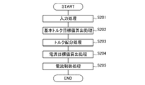
- FIG. 2 is a flowchart illustrating a main process of a control method for an electric four-wheel drive vehicle according to the present embodiment.
- FIG. 3 is a graph showing an example of an accelerator opening-torque table.
- FIG. 4 is a block diagram showing a configuration of torque distribution processing.
- FIG. 5 is a block diagram showing the configuration of the second correction process.
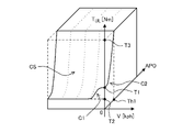
- FIG. 6 is a map showing an upper limit value set in the torque limit imposed at the time of rollback.
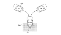
- FIG. 7 is an explanatory diagram showing an example of a situation in which an electric four-wheel drive vehicle may roll back.
- FIG. 1 is a block diagram illustrating a configuration of an electric four-wheel drive vehicle that executes a control method for the electric four-wheel drive vehicle according to the present embodiment.
- FIG. 2 is a flowchart illustrating
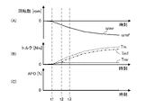
- FIG. 8 is a graph showing changes in wheel rotation speed, torque, and accelerator opening degree in a comparative example in which torque limitation is not applied.
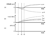
- FIG. 9 is a graph showing changes in wheel rotation speed, torque, and accelerator opening when torque limitation is applied.
- FIG. 10 is an explanatory diagram showing a situation in which the same operation as during rollback may be exhibited.
- FIG. 11 is a block diagram showing the configuration of the second correction process of the modified example.
- FIG. 1 is a block diagram illustrating a configuration of an electric four-wheel drive vehicle that executes a control method for the electric four-wheel drive vehicle according to the present embodiment.
- the electric vehicle is a vehicle that is equipped with an electric motor (hereinafter, simply referred to as a motor) as a drive source and can travel by generating a driving force generated by the torque generated by the motor on one or a plurality of wheels. Therefore, the electric vehicle includes, in addition to the so-called electric vehicle, a hybrid vehicle in which a motor and an engine are used in combination as a drive source. For example, an electric vehicle also includes a hybrid vehicle that uses a motor as a drive source for one of the front and rear wheels and an engine as a drive source for the other wheel.
- a four-wheel drive vehicle is a vehicle that can use four wheels as drive wheels.
- the four-wheel drive vehicle includes a vehicle that always uses four wheels as drive wheels, and a vehicle that can be switched between so-called front-wheel drive or rear-wheel drive two-wheel drive. Further, in a four-wheel drive vehicle, a part of the four wheels can be interlocked and controlled as a drive wheel, and the four wheels may be controlled as a drive wheel that drives independently.
- the electric four-wheel drive vehicle means a vehicle that can travel by generating a driving force due to the torque generated by the motor on some or all of the four wheels.
- the vehicle 100 is an electric four-wheel drive vehicle.
- the vehicle 100 includes a front drive system fds, a rear drive system rds, a battery 1, and a motor controller 2 (controller).
- the front drive system fds is a system that receives electric power from the battery 1 and drives the front wheels 9f under the control of the motor controller 2.
- the front drive system fds includes a front inverter 3f, a front drive motor 4f, a front reducer 5f, a front rotation sensor 6f, a front drive shaft 8f, a front wheel 9f, and the like.
- the front wheel 9f is a pair of wheels relatively in the front direction of the vehicle 100 among the four wheels included in the vehicle 100.
- the front direction of the vehicle 100 is a predetermined direction formally determined according to the direction of the passenger's seat and the like. Further, by the front drive system fds, the front wheels 9f function as drive wheels for generating the driving force of the vehicle 100.
- the rear drive system rds is a system that receives electric power from the battery 1 and drives the rear wheels 9r under the control of the motor controller 2.
- the rear drive system rds includes a rear inverter 3r, a rear drive motor 4r, a rear speed reducer 5r, a rear rotation sensor 6r, a rear drive shaft 8r, and a rear wheel 9r in symmetry with the front drive system fds.
- the rear wheel 9r is a pair of wheels relatively rearward of the vehicle 100 among the four wheels included in the vehicle 100.
- the rear direction of the vehicle 100 means a direction opposite to the front direction of the vehicle 100.
- the rear wheels 9r function as drive wheels that generate the driving force of the vehicle 100.
- Battery 1 is connected to the motor via an inverter and discharges to supply drive power to the motor. Further, the battery 1 can be charged by receiving the supply of regenerative power from the motor.
- the battery 1 In the front drive system fds, the battery 1 is connected to the front drive motor 4f via the front inverter 3f.
- the battery 1 in the rear drive system rds, the battery 1 is connected to the rear drive motor 4r via the rear inverter 3r.
- the motor controller 2 is a control device for the vehicle 100.
- the motor controller 2 is, for example, a computer composed of a central arithmetic unit (CPU), a read-only memory (ROM), a random access memory (RAM), an input / output interface (I / O interface), and the like.
- the motor controller 2 generates a control signal for controlling the front drive motor 4f and the rear drive motor 4r based on the vehicle variables of the vehicle 100.
- the motor controller 2 controls the operations of the front wheels 9f and the rear wheels 9r by controlling the front drive motor 4f and the rear drive motor 4r, respectively.
- the vehicle variable is information indicating the operating state or control state of the entire vehicle 100 or each part constituting the vehicle 100.
- Vehicle variables can be obtained by detection, measurement, calculation, or the like. For example, accelerator opening, shift lever range signal, vehicle speed, yaw rate, DC voltage value of battery 1, steering angle, and rotor phase of each motor, three-phase AC current, electric angular velocity, rotational speed, rotation speed, wheels.
- the speed and the like are vehicle variables of the vehicle 100.
- the motor controller 2 controls the front drive motor 4f and the rear drive motor 4r, respectively, using these vehicle variables input as digital signals, for example.
- the control signal for controlling the front drive motor 4f and the rear drive motor 4r is, for example, a PWM signal (Pulse Width Modulation signal) that controls the current of each of these motors.
- the motor controller 2 generates drive signals for the front inverter 3f and the rear inverter 3r according to the generated PWM signals.
- the front inverter 3f and the rear inverter 3r have, for example, the power of two switching elements (for example, an IGBT (Insulated Gate Bipolar Transistor)) or a MOS-FET (metal-oxide-semiconductor field-effect transistor) corresponding to each phase. It is equipped with a semiconductor element).
- Each of these inverters converts the direct current supplied from the battery 1 into an alternating current by turning on / off the switching element according to the drive signal generated by the motor controller 2, and the front drive motor 4f and the rear drive, respectively.
- the current supplied to the motor 4r is adjusted.
- each inverter reversely converts the alternating current generated by the front drive motor 4f and the rear drive motor 4r by the regenerative braking force into a direct current, and adjusts the current supplied to the battery 1.
- the front drive motor 4f and the rear drive motor 4r are, for example, three-phase AC motors, and generate driving force (torque) by an AC current supplied from a connected inverter.
- the driving force generated by the front drive motor 4f is transmitted to the front wheels 9f via the front reducer 5f and the front drive shaft 8f.
- the driving force generated by the rear drive motor 4r is transmitted to the rear wheels 9r via the rear reducer 5r and the rear drive shaft 8r.
- a regenerative braking force is generated and the kinetic energy of the vehicle 100 is recovered as electric energy.
- the front drive motor 4f is a drive source (front drive source) for driving the front wheels 9f.
- the rear drive motor 4r is a drive source (rear drive source) that drives the rear wheels 9r independently of the front wheels 9f.
- the front speed reducer 5f and the rear speed reducer 5r are composed of, for example, a plurality of gears. Each of these speed reducers reduces the rotational speed of the motor to which it is connected and transmits it to the drive shaft to generate drive torque or braking torque (hereinafter, simply referred to as torque) proportional to the reduction ratio.
- torque drive torque or braking torque
- the front rotation sensor 6f and the rear rotation sensor 6r detect the rotor phase of the motor to which they are connected and output them to the motor controller 2.
- the front rotation sensor 6f and the rear rotation sensor 6r are, for example, a resolver or an encoder.
- the front current sensor 7f and the rear current sensor 7r each detect the current flowing through the connected motor and output it to the motor controller 2. In this embodiment, these current sensors detect the three-phase alternating current of each motor.
- the front current sensor 7f and the rear current sensor 7r may be used to detect an arbitrary two-phase current, and the remaining one-phase current may be obtained by calculation.
- the vehicle 100 includes a front rotation sensor 6f and a front current sensor 7f incorporated in the front drive system fds, a rear rotation sensor 6r and a rear current sensor 7r incorporated in the rear drive system rds, and various other sensors 15.
- Other various sensors 15 include, for example, an accelerator opening sensor 15a, an acceleration sensor (not shown), a speed sensor (not shown), a yaw rate sensor 15b, a GPS (Global Positioning System) sensor (not shown), and / or.
- Various sensors such as steering angle sensor (not shown) are included.
- the accelerator opening sensor 15a detects an accelerator opening APO, which is an operation amount of the accelerator (not shown).
- the accelerometer detects the anteroposterior and / or lateral acceleration of the vehicle 100.
- the speed sensor detects the vehicle speed V of the vehicle 100.
- the vehicle speed V is the moving speed (body speed) of the entire vehicle body of the vehicle 100.
- the yaw rate sensor 15b detects the yaw rate of the vehicle 100.
- the GPS sensor detects the position information of the vehicle 100.
- the steering angle sensor detects the steering angle of the steering wheel (not shown).
- the detection values detected by these various sensors 15 are input to the motor controller 2. That is, the motor controller 2 can acquire the detected vehicle variables such as the accelerator opening APO, the acceleration in the front-rear direction, the acceleration in the lateral direction, the yaw rate, the position information, and the steering angle as necessary.
- the motor controller 2 can arbitrarily acquire the operation or setting state of various devices (not shown) included in the vehicle 100 as vehicle variables.
- the motor controller 2 can acquire the input state from the shift lever 16 for operating the transmission (not shown).
- the vehicle 100 is an automatic transmission
- the shift lever 16 of the vehicle 100 is a so-called selector. Therefore, the motor controller 2 has a signal (“D”) indicating a range such as parking (“P”), reverse (“R”), neutral (“N”), and drive (“D”) as the input state of the shift lever 16.
- D a signal
- the motor controller 2 determines the driving direction and the like of the vehicle 100 intended by the driver.
- the motor controller 2 determines that the driving direction of the vehicle 100 intended by the driver is the forward direction, and controls to drive the vehicle 100 in the forward direction. Run. Therefore, when the range signal SFT is in the D range, the driving direction of the vehicle 100 is the forward direction. Further, when the range signal SFT is in the R range, the motor controller 2 determines that the driving direction of the vehicle 100 intended by the driver is the rear direction, and controls to drive the vehicle 100 in the rear direction. Run. Therefore, when the range signal SFT is in the R range, the drive direction of the vehicle 100 is the rear direction.
- FIG. 2 is a flowchart illustrating the main processing of the control method of the electric four-wheel drive vehicle according to the present embodiment.
- the motor controller 2 executes an input process S201, a basic torque target value calculation process S202, a torque distribution process S203, a current target value calculation process S204, and a current control process S205.
- the motor controller 2 is programmed to execute these processes at predetermined calculation cycles.
- the input process S201 is a process in which the motor controller 2 acquires vehicle variables by receiving inputs from various sensors 15 and the like. Further, among the parameters used in the subsequent processing, those that cannot be directly obtained as vehicle variables are acquired by the motor controller 2 by calculation or the like using the vehicle variables in the input processing S201.
- the motor controller 2 has an accelerator opening APO [%], a rotor phase [rad] and a three-phase alternating current [A] of each motor, a range signal SFT of the shift lever 16, and a vehicle speed V [km / h], yaw rate YR [deg / sec], and DC voltage value Vdc [V] of the battery 1 are acquired from various sensors 15 and the like.
- the motor controller 2 acquires the drive direction of the vehicle 100 based on the range signal SFT indicating the input state of the shift lever 16.
- the motor controller 2 has a motor electric angular velocity ⁇ e [rad / s], a motor rotation speed ⁇ m [rad / s], a motor rotation speed Nm [rpm], and a wheel speed ⁇ w [km / h]. Is obtained by calculation as follows.
- Motor electric angular velocity ⁇ e The motor controller 2 obtains each motor electric angular velocity ⁇ e by time-differentiating the rotor phase ⁇ . That is, the motor controller 2 obtains the front motor electric angular velocity ⁇ ef by differentiating the rotor phase ⁇ f of the front drive motor 4f. Further, the motor controller 2 obtains the rear motor electric angular velocity ⁇ er by differentiating the rotor phase ⁇ r of the rear drive motor 4r.
- the motor controller 2 divides the motor electric angular velocity ⁇ e by the number of pole pairs of the motor to calculate the motor rotation speed ⁇ m, which is the mechanical angular velocity. That is, the motor controller 2 calculates the front motor rotation speed ⁇ mf by dividing the front motor electric angular velocity ⁇ ef by the number of pole pairs of the front drive motor 4f. Similarly, the motor controller 2 calculates the rear motor rotation speed ⁇ mr by dividing the rear motor electric angular velocity ⁇ er by the number of pole pairs of the rear drive motor 4r.
- the motor controller 2 acquires the actual moving direction of the vehicle 100 based on the positive and negative of the calculated front motor rotation speed ⁇ mf and / or the rear motor rotation speed ⁇ mr.
- the actual moving direction means the direction in which the vehicle 100 actually moves regardless of the input state of the shift lever 16. For example, if the vehicle 100 turns the front direction toward the uphill direction and the input state of the shift lever 16 is in the D range, but the vehicle 100 actually rolls back toward the downhill direction, the actual moving direction. Is the downhill direction, that is, the rear direction of the vehicle 100.
- the motor controller 2 acquires the actual moving direction of the vehicle 100 by the positive / negative of the front motor rotation speed ⁇ mf.
- the motor controller 2 calculates the motor rotation speed Nm by multiplying the motor rotation speed ⁇ m by the unit conversion coefficient (60 / 2 ⁇ ). That is, the motor controller 2 calculates the front motor rotation speed Nmf by converting the unit of the front motor rotation speed ⁇ mf. Similarly, the motor controller 2 calculates the rear motor rotation speed Nmr by converting the unit of the rear motor rotation speed ⁇ mr.
- the motor controller 2 calculates the front wheel speed ⁇ wf, which is the wheel speed of the front wheels 9f, based on the value obtained by multiplying the front motor rotation speed ⁇ mf by the driving radius Rf of the front wheels 9f and the gear ratio of the front speed reducer 5f.
- the rear wheel speed ⁇ wr which is the wheel speed of the rear wheels 9r, is based on the value obtained by multiplying the rear motor rotation speed ⁇ m by the driving radius Rr of the rear wheels 9r and the gear ratio of the rear speed reducer 5r. Is calculated.
- a unit conversion coefficient is applied to the front wheel speed ⁇ wf and the rear wheel speed ⁇ wr obtained as described above, and the unit [m / s] of the front wheel speed ⁇ wf and the rear wheel speed ⁇ wr is [km / h]. Is converted to.
- the basic torque target value calculation process S202 is a process in which the motor controller 2 calculates the basic torque target value Tm0 * based on the vehicle variables.
- the basic torque target value Tm0 * is the torque (so-called required torque) required by the driver for the vehicle 100 by operating the accelerator or the like.
- the basic torque target value Tm0 * is a target value for the total amount of torque generated by the front drive motor 4f and torque generated by the rear drive motor 4r.
- the motor controller 2 refers to the accelerator opening-torque table shown in FIG. 3 and calculates the basic torque target value Tm0 * based on the accelerator opening APO and the motor rotation speed ⁇ m.
- the motor controller 2 refers to the accelerator opening-torque table
- the front motor rotation speed ⁇ mf, the rear motor rotation speed ⁇ mr, an average value thereof, or the like can be used as the motor rotation speed ⁇ m.
- the motor controller 2 calculates the basic torque target value Tm0 * by using the front motor rotation speed ⁇ mf.
- the basic torque target value Tm0 * is a positive value in a predetermined range in the range where the motor rotation speed ⁇ m is negative. This is a setting for suppressing the rollback of the vehicle 100 or reducing the movement amount and / or the movement speed of the rollback. That is, in the basic torque target value calculation process S202, the positive basic torque target value Tm0 * is calculated in a predetermined range within the range where the motor rotation speed ⁇ m is negative, so that the front wheels 9f and the rear wheels 9r are set during rollback. On the other hand, a basic driving force that suppresses the movement of the vehicle 100 in the actual movement direction is set.
- the motor controller 2 sets an upper limit value for the torque distributed to the wheels on the low ⁇ road surface.
- the motor controller 2 distributes the basic torque target value Tm0 * to the target value of the torque generated by the front drive motor 4f and the target value of the torque generated by the rear drive motor 4r. It is a process to do. That is, the torque distribution process S203 is a process of distributing the basic torque target value Tm0 * to the front wheels 9f and the rear wheels 9r.
- FIG. 4 is a block diagram showing the configuration of the torque distribution process S203.
- the torque distribution process S203 includes a first correction process S410, a distribution ratio multiplication process S420, a second correction process S430, a front torque target value calculation process S440, a feedback process S450, and a rate limiter process S460. include.
- (1) First correction process In the first correction process S410, the driving force generated by the front wheels 9f and the rear wheels 9r by correcting the basic torque target value Tm0 * before distribution to the front wheels 9f and the rear wheels 9r.
- the total amount of is limited.
- the first torque target value Tm1 * is calculated by multiplying the basic torque target value Tm0 * by a predetermined coefficient ⁇ .
- the predetermined coefficient ⁇ to be multiplied by the basic torque target value Tm0 * represents the limit amount of the basic torque target value Tm0 * . Therefore, the predetermined coefficient ⁇ is, for example, a positive number of 1 or less. Further, the predetermined coefficient ⁇ is determined based on the yaw feedback torque Ty.
- the yaw feedback torque Ty is a torque for reducing the lateral slip of the vehicle 100 by feeding back to the first correction process S410 as described above.
- the yaw feedback torque Ty is calculated in the yaw feedback control S411.
- the yaw feedback torque Ty is calculated based on the steering angle, the yaw rate YR, and the deviation between the yaw rate YR and its target value (hereinafter referred to as the yaw rate target value).
- the yaw rate target value is determined, for example, based on the vehicle speed V and the steering angle.
- the basic torque target value Tm0 * is limited by a predetermined coefficient ⁇ determined based on the yaw feedback torque Ty, so that the driving force generated in the front wheels 9f and the rear wheels 9r is limited according to the yaw rate YR. ..
- the yaw rate YR is reduced, thus reducing lateral slip or the possibility of lateral slip of the vehicle 100.
- the first rear torque target value Tm1r * is calculated by multiplying the first torque target value Tm1 * by a predetermined distribution ratio ⁇ .
- the distribution ratio ⁇ is determined in the distribution ratio determination process S421, for example, based on the setting of the traveling mode, the transition of the position of the center of gravity of the vehicle 100, or the like. Further, in the present embodiment, the first distribution ratio that prioritizes energy efficiency, the second distribution ratio that emphasizes running stability, and the like are predetermined, and in the distribution ratio determination process S421, these distribution ratios are set. The distribution ratio is selected according to.
- Second correction process In the second correction process S430, various correction processes and the like are applied to the first rear torque target value Tm1r * , and the second rear torque target value Tm2r * is calculated.
- the second rear torque target value Tm2r * becomes the rear torque target value Tmr * after being corrected by the feedback process S450 and the rate limiter process S460.
- the rear torque target value Tmr * is a torque target value distributed to the rear wheels 9r among the first torque target values Tm1 * . That is, the rear torque target value Tmr * is the final target value of the torque output by the rear drive motor 4r with respect to the rear wheel 9r. Therefore, the motor controller 2 controls the rear drive motor 4r based on the rear torque target value Tmr * .
- the torque generated in the rear wheel 9r by the control based on the final rear torque target value Tmr * is the rear torque Tmr (see FIG. 9).
- the second correction process S430 is a feedforward control for determining a target value based on the current vehicle variable or the like.
- the first front torque target value Tm1f * is calculated by subtracting the second rear torque target value Tm2r * from the first torque target value Tm1 * . Will be done.
- the first front torque target value Tm1f * becomes the front torque target value Tmf * after being corrected by the feedback process S450 and the rate limiter process S460.
- the front torque target value Tmf * is a target value of torque to be distributed to the front wheels 9f in the first torque target value Tm1 * . That is, the front torque target value Tmf * is the final target value of the torque output by the front drive motor 4f with respect to the front wheels 9f.
- the motor controller 2 controls the front drive motor 4f based on the front torque target value Tmf * .
- the actual torque generated in the front wheels 9f by the control based on the final front torque target value Tmf * is the front torque Tmf (see FIG. 9).
- the total amount of the rear torque Tmr and the front torque Tmf is the total torque Tm (see FIG. 9).
- the second rear torque target value Tm2r * is a reduction of the first rear torque target value Tm1r * by torque limitation. Therefore, in the front torque target value calculation process S440, the calculation of subtracting the second rear torque target value Tm2r * from the first torque target value Tm1 * is substantially the reduction of the rear torque (torque of the rear wheel 9r) due to the torque limitation. Is added to the front torque (torque of the front wheel 9f). Therefore, the first torque target value Tm1 * , which is the total amount of torque distributed to the front wheels 9f and the rear wheels 9r, is maintained.
- the reduced driving force is added to the driving force generated in the front wheels 9f, and the front wheels 9f are larger than the basic driving force. It is driven by a driving force.
- the first front torque target value Tm1f * is calculated by subtracting the second rear torque target value Tm2r * from the first torque target value Tm1 * .
- Substantially all of the rear torque reduction due to torque limitation is added to the front torque.
- a part of the reduction in the rear torque due to the torque limitation may be added to the front torque.
- the first torque target value Tm1 * is multiplied by the distribution ratio "1- ⁇ ", and a part of the difference between the first rear torque target value Tm1r * and the second rear torque target value Tm2r * is added to the result.
- 1 Front torque target value Tm1f * may be calculated.
- the feedback torque FBTf is, for example, a deviation ⁇ m (not shown) between the front motor rotation speed ⁇ mf and the rear motor rotation speed ⁇ mr, and / or a deviation ⁇ mf (not shown) between the target value (estimated value) of the front motor rotation speed ⁇ mf and the measured value. Not), etc.
- the feedback torque FBTr is, for example, a deviation ⁇ m between the front motor rotation speed ⁇ mf and the rear motor rotation speed ⁇ mr, and / or a deviation ⁇ mr between the target value (estimated value) of the rear motor rotation speed ⁇ mr and the measured value (not shown). ), Etc. are calculated.
- the feedback torques FBTf and FBTr are calculated based on the deviation ⁇ m between the front motor rotation speed ⁇ mf and the rear motor rotation speed ⁇ mr.
- the deviation ⁇ m represents the difference between the rotation speeds (or rotation speeds) of the front wheels 9f and the rear wheels 9r, and is related to the slip of the front wheels 9f and the rear wheels 9r. Therefore, the addition of the feedback torques FBTf and FBTr calculated based on the deviation ⁇ m suppresses or reduces the slip of the front wheels 9f and the rear wheels 9r, respectively.
- Rate limiter processing In the rate limiter processing S460, the rate of change is relative to the first front torque target value Tmf1 * to which the feedback torque FBTf is added and the second rear torque target value Tmr2 * to which the feedback torque FBTr is added. An upper limit is set for.
- the rate limiter treatment S460 prevents or reduces slippage of the front wheels 9f and the rear wheels 9r.
- the dq-axis current target values of the front drive motor 4f and the rear drive motor 4r are calculated.
- the dq-axis current target value of the front drive motor 4f is calculated by referring to a predetermined table determined in advance based on the front torque target value Tmf * and the DC voltage value Vdc of the battery 1.
- the dq-axis current target value of the rear drive motor 4r is calculated by referring to a predetermined table determined in advance based on the rear torque target value Tmr * and the DC voltage value Vdc of the battery 1.
- the dq-axis current value is calculated based on the three-phase alternating current value and the rotor phase.
- the dq-axis voltage command value is calculated from the deviation between the dq-axis current value and the dq-axis current target value calculated in the current target value calculation process S204.
- the three-phase AC voltage command value is calculated based on the dq-axis voltage command value and the rotor phase.
- the PWM signal is obtained based on the three-phase AC voltage command value and the DC voltage value Vdc of the battery 1.
- dq-axis current value, dq-axis voltage command value, three-phase AC voltage command value, and PWM signal are calculated for the front drive motor 4f and the rear drive motor 4r, respectively.
- the front drive motor 4f and the rear drive motor 4r have the front torque target value Tmf * and the rear torque target value Tmr, respectively. It is driven by the torque specified by * .
- FIG. 5 is a block diagram showing the configuration of the second correction process S430.
- the second correction process S430 includes a reversal determination process S510, an upper limit value calculation process S520, and a minimum value process S530.
- (A) Reversal determination process In the reversal determination process S510, it is determined whether or not the actual moving direction of the vehicle 100 is reversed with respect to the driving direction of the vehicle 100.
- the drive direction of the vehicle 100 is determined by the range signal SFT of the shift lever 16. Further, in the present embodiment, the actual moving direction of the vehicle 100 is determined by the front motor rotation speed ⁇ mf.
- This reversal determination process S510 determines, for example, whether or not the vehicle 100 rolls back or whether or not the vehicle 100 rolls back when the vehicle 100 is on a slope. That is, it is determined whether or not the driving direction of the vehicle 100 indicated by the range signal SFT and the actual moving direction of the vehicle 100 indicated by the front motor rotation speed ⁇ mf are different.
- a negative front motor rotation speed ⁇ mf is output.
- the front motor rotation speed ⁇ mf is a negative value even though the range signal SFT is in the D range
- the drive direction of the vehicle 100 is in the forward direction
- the actual movement direction is in the rear direction.
- This is, for example, a rollback scene in which the vehicle 100 retreats on an uphill road.
- the front motor rotation speed ⁇ mf is a positive value even though the range signal SFT is in the R range
- the drive direction of the vehicle 100 is the rear direction
- the actual movement direction is the front direction. be.
- rollback means that the vehicle 100 moves in the direction opposite to the driving direction. Therefore, the rollback includes not only the case where the vehicle 100 moves in the rear direction but also the case where the vehicle 100 moves in the forward direction as described above.
- the reversal determination process S510 includes a multiplication process S511 and an output selection process S512.
- the output selection process S512 one of the front motor rotation speed ⁇ mf whose sign is inverted in the multiplication process S511 and the calculated front motor rotation speed ⁇ mf (front motor rotation speed ⁇ mf before the code inversion) is selected. It is output for use in the upper limit value calculation process S520.
- This selection is made based on the range signal SFT of the shift lever 16. Specifically, when the range signal SFT of the shift lever 16 is in the R range, the front motor rotation speed ⁇ mf whose sign is inverted is selected. Further, when the range signal SFT of the shift lever 16 is in the D range, the front motor rotation speed ⁇ mf before sign inversion is selected. As a result, in the output selection process S512, when the vehicle 100 rolls back, a negative front motor rotation speed ⁇ mf is output.
- the upper limit value T UL is calculated based on the vehicle speed V and the accelerator opening APO.
- the upper limit value T UL calculated in the upper limit value calculation process S520 is used in the minimum value process S530.
- the upper limit value T UL functions as a torque limit imposed on the first rear torque target value Tmr1 * at the time of rollback.
- FIG. 6 is a map showing an upper limit value T UL set in the torque limit imposed at the time of rollback.
- the upper limit value T UL is set according to the value of the accelerator opening APO in the range where the vehicle speed V is zero or less.
- the vehicle speed V shown in FIG. 6 can be directly acquired as a vehicle variable, but the front motor rotation speed ⁇ mf or the rear motor rotation speed ⁇ m, which is the motor rotation speed ⁇ m, is set to the vehicle speed (rear wheel speed ⁇ w, which is the wheel speed ⁇ w). ), which can be used instead of the vehicle speed V.
- the front motor rotation speed ⁇ mf output as the determination result of the reversal determination process S510 is converted into the vehicle speed V and used.
- the upper limit value T UL (hereinafter referred to as the basic upper limit value) when the vehicle speed V is zero and the accelerator opening APO is zero is "T1".
- This basic upper limit value T1 is smooth without forming a step with respect to the normal torque distributed when the vehicle speed V is a positive value, that is, the torque distributed when the driving direction and the actual moving direction match. It is a predetermined value for connecting to.
- the upper limit value T UL is set to smoothly decrease from the basic upper limit value T1 according to the predetermined slope C1 in a predetermined range in which the absolute value of the vehicle speed V is relatively small. ..
- the presence of the slope C1 ensures robustness against fluctuations in the vehicle speed V, that is, against fluctuations in the motor rotation speed ⁇ m.
- the specific shape of the slope C1 is predetermined by an experiment, a simulation, or the like.
- the upper limit value T UL is, for example, a constant value . It is set to a predetermined value T2.
- This predetermined value T2 is a value to the extent that the wheel idling is suppressed, and is predetermined by an experiment, a simulation, or the like.
- the larger the vehicle speed V the smaller the upper limit value T UL from the basic upper limit value T1. It is preferable to set the value to and increase the torque limit as the vehicle speed V increases.
- the upper limit value T UL is set to increase from the basic upper limit value T1 to the maximum value T3 in the range where the accelerator opening APO is equal to or less than the predetermined threshold value Th1.
- the predetermined threshold value Th1 is, for example, a value that defines a range in which the accelerator opening degree APO is substantially zero.
- the maximum value T3 is set sufficiently larger than the value that can be input as the first rear torque target value Tm1r * that sets the upper limit value TUL. That is, the range in which the upper limit value T UL becomes the maximum value T 3 substantially cancels the torque limit. Therefore, torque limitation is not substantially implemented in the accelerator opening APO larger than the threshold Th1.
- the range in which the upper limit value T UL becomes the maximum value T3 is the range in which the accelerator opening APO is the threshold value Th1 or more regardless of the vehicle speed V. Therefore, the upper limit value T UL acts in a range in which the accelerator opening APO below the threshold value Th1 becomes substantially zero.
- the upper limit value T UL is set so as to smoothly increase from the basic upper limit value T1 according to a predetermined slope C2.
- the presence of the slope C2 ensures robustness against fluctuations in the accelerator opening APO.
- the specific shape of the slope C2 is predetermined based on an experiment, a simulation, or the like.
- the curved surface CS of the upper limit value T UL formed in the range where the vehicle speed V is zero or less and the accelerator opening APO is the threshold Th1 or less has smooth convex portions formed by the slopes C1 and C2. , It is defined so that steep irregularities and discontinuities are not formed. As a result, robustness is ensured against fluctuations in the motor rotation speed ⁇ m and the accelerator opening APO within the range of the vehicle speed V and the accelerator opening APO to which the upper limit value T UL is applied.
- the first rear torque target value Tmr1 * and the upper limit value T UL calculated in the upper limit value calculation processing S520 are compared, and the smaller value among these is the second rear torque target. It is output as the value Tmr2 * .
- the second rear torque target value Tmr2 * in which the first rear torque target value Tmr1 * is limited to the upper limit value T UL or less is output. That is, in the minimum value processing S530, the torque limit that limits the first rear torque target value Tmr1 * to the upper limit value T UL or less is executed.
- the upper limit value T UL is the maximum value T3, and the torque limit is substantially released. Therefore, the first rear torque target value Tmr1 * remains as it is. It is output as the second rear torque target value Tmr2 * .
- the second correction process S430 outputs the second rear torque target value Tm2r * in which the first rear torque target value Tm1r * is limited to the upper limit value T UL or less.
- the second rear torque target value Tm2r * output as a result of the second correction process S430 finally becomes the rear torque target value Tmr * through the feedback process S450 and the rate limiter process S460.
- the front wheels 9f and the rear wheels 9r have a front-rear relationship or a priority relationship.
- a front-rear relationship in which the torque to be distributed to the rear wheels 9r is determined first, and the torque to be distributed to the front wheels 9f is determined accordingly.
- the upper limit value T UL is set for the torque of the rear wheels 9r (second rear torque target value Tmr2 * ) by using the rotation speed of the front wheels 9f (front motor rotation speed ⁇ mf).
- the front motor rotation speed ⁇ mf is used instead of the rear motor rotation speed ⁇ mr.
- the motor controller 2 controls the vehicle 100 by exchanging these predecessor relationships and priority relationships as necessary. That is, the motor controller 2 first calculates the torque of the front wheels 9f in the same manner as determining the torque of the rear wheels 9r in the torque distribution process S203 shown in FIG. 4, and is the total amount of torque to be distributed thereafter.
- the torque of the rear wheel 9r may be calculated by subtracting the calculated torque of the front wheel 9f from the torque target value Tm1 * .
- the second correction process S430 is performed on the torque of the front wheel 9f, and the upper limit value T UL is set in the torque of the front wheel 9f.
- the rear motor rotation speed ⁇ mr is used instead of the front motor rotation speed ⁇ mf in the reverse rotation determination process S510 and the upper limit value calculation process S520.
- the vehicle speed V is converted from the motor rotation speed ⁇ m and obtained, the rear motor rotation speed ⁇ mr is used.
- the motor controller 2 determines whether or not the drive direction of the vehicle 100 and the actual movement direction are different by the reverse rotation determination process S510. Then, as a result of this reversal determination process S510, when the driving direction of the vehicle 100 and the actual moving direction are different, the torque to be distributed to one of the front wheels 9f and the rear wheels 9r is set to the upper limit value T UL or less.
- Limit torque Limit torque limit
- the driving force generated on one of the front wheels 9f and the rear wheels 9r has an upper limit value P UL corresponding to the upper limit value T UL (not shown).
- driving force limit Is set (hereinafter referred to as driving force limit). Further, one wheel whose driving force is limited by this driving force limitation is driven with a driving force smaller than the basic driving force generated by the feedback torques FBTf and FBTr.
- FIG. 7 is an explanatory diagram showing an example of a situation in which an electric four-wheel drive vehicle may roll back. Further, the vehicle 700 of the comparative example shown in FIG. 7 is a vehicle that performs the same control as the vehicle 100 according to the above embodiment except that the torque limitation in the second correction process S430 is not performed.
- the vehicle 700 of the comparative example is stopped on the slope 701 with the front direction facing the slope direction.
- the road surface of the slope 701 is, for example, a snow-packed road surface 710, and a part thereof includes a frozen road surface (so-called ice burn) 711 which is a relatively low ⁇ road surface with respect to the snow-packed road surface 710.
- ice burn frozen road surface
- the driving direction of the vehicle 700 of the comparative example intended by the driver is the forward direction (that is, the vehicle).
- rollback may occur in which the vehicle 700 moves in the rear direction A1 before the accelerator pedal is operated, that is, in a state where the accelerator opening APO is zero.
- the motor controller 2 of the vehicle 700 of the comparative example generates a basic driving force for driving the vehicle 100 in the driving direction on the front wheels 9f and the rear wheels 9r.
- the occurrence of rollback is suppressed, or the rollback speed or the like is reduced.
- the front wheels 9f are on the snow-packed road surface 710 and the rear wheels 9r are on the frozen road surface 711, and there is a difference in the road surface resistance ⁇ between the front wheels 9f and the rear wheels 9r. Therefore, when the basic driving force is generated on the front wheels 9f and the rear wheels 9r, the front wheels 9f gripping the snow-packed road surface 710 are, for example, balanced with the force that the vehicle 100 tries to roll back, or are brought to the rollback of the vehicle 100. It is rotated backward toward A2.
- the movement of the front wheels 9f is the movement of the wheels that the driver naturally predicts.
- the rear wheel 9r does not grip because it is on the frozen road surface 711, which is a low ⁇ road surface. Therefore, in the vehicle 700 of the comparative example, when the basic driving force is generated in the rear wheels 9r, the rear wheels 9r slip in the front direction A3 which is the driving direction. Since almost all of the basic driving force generated in the rear wheels 9r is used for this idling, the idling speed of the rear wheels 9r is steeply generated. Further, even from the vehicle speed V due to the rollback experienced by the driver, the idling of the rear wheels 9r is a high-speed rotation speed exceeding the prediction of a normal driver.
- this idling of the rear wheels 9r does not substantially operate the accelerator leading to the rotation of the wheels, and occurs even when the accelerator opening APO is zero. Therefore, the idling of the rear wheel 9r that occurs in the vehicle 700 of the comparative example may give a sense of discomfort to the driver.
- FIG. 8 is a graph showing changes in wheel rotation speed, torque, and accelerator opening in a comparative example in which torque limitation is not applied.
- FIG. 8A when the vehicle 700 of the comparative example starts rolling back at time t1, the front wheels 9f and the rear wheels 9r of the vehicle 700 of the comparative example rotate with the rollback, so that the front wheels are rotated.
- the motor rotation speed ⁇ mf and the rear motor rotation speed ⁇ mr decrease.
- the total torque Tm of the front wheels 9f and the rear wheels 9r is increased by the feedback process S450.
- time t1 to t2 there is no substantial difference between the front torque Tmf, which is the torque of the front wheels 9f, and the rear torque Tmr, which is the torque of the rear wheels 9r.
- the rear motor rotation speed ⁇ mr increases as shown in FIG. 8A.
- the rear motor rotation speed ⁇ mr rotates (forward rotation) toward the drive direction even though the front wheel 9f is rotating in the actual movement direction due to rollback. Therefore, after the time t3, the rotation directions of the front wheels 9f and the rear wheels 9r are reversed.
- the rear motor rotation speed ⁇ mr continues to rise, and the idling of the rear wheel 9r does not stop.
- the torque distribution process S203 is executed without the torque limitation being executed. Therefore, the front is fronted between the time t2 and the time t3 and after the time t3. There is no substantial difference between the torque Tmf and the rear torque Tmr.
- FIG. 9 is a graph showing changes in wheel rotation speed, torque, and accelerator opening when torque limitation is implemented. That is, when the vehicle 100 of the present embodiment is in the same situation as the vehicle 700 of the above comparative example, as shown in FIG. 9A, when the vehicle 100 starts to roll back from time t1, the front wheels 9f and the rear wheels 9f and the rear Since the wheel 9r rotates along with the rollback, the front motor rotation speed ⁇ mf and the rear motor rotation speed ⁇ mr decrease. Further, as shown in FIG. 9B, the total torque Tm is increased by the rollback of the vehicle 100, and there is no substantial difference between the front torque Tmf and the rear torque Tmr. These are the same as the vehicle 700 of the comparative example.
- the vehicle 100 executes the torque limitation in the second correction process S430.
- the second rear torque target value Tm2r * becomes a value limited by the upper limit value T UL .
- the rear torque Tmr becomes a value determined by the upper limit value T UL .
- the front torque target value Tmf * is calculated by subtracting the rear torque target value Tmr * from the first torque target value Tm1 * , the total torque Tm is maintained.
- the decrease in rear torque Tmr due to torque limitation is compensated for by the increase in front torque Tmf.
- the rear wheel 9r when the rear torque Tmr is limited by the upper limit value T UL as described above, the rear wheel 9r generates a driving force within a range substantially gripping the frozen road surface 711. Therefore, the rear wheel 9r does not substantially slip and maintains the rotation guided by the rollback like the front wheel 9f. Therefore, as shown in FIG. 9A, the rear motor rotation speed ⁇ mr continues to have substantially the same value as the front motor rotation speed ⁇ mf even after the time t2. That is, even if the rear wheels 9r do not slip and the rear wheels slip very slightly at the moment of time t2, the driver can naturally tolerate the operation of the vehicle 100 as a predictable behavior during rollback. Therefore, the driver does not feel a sense of discomfort from the vehicle 100 during rollback.
- the conditions for accelerator operation are the same as in the case of the vehicle 700 in the above-mentioned comparative example. That is, as shown in FIG. 9C, the above-mentioned operation of the vehicle 100 is an operation while the driver does not operate the accelerator at all and the accelerator opening APO continues to be zero.
- the control method of the electric four-wheel drive vehicle is a front drive source (front drive motor 4f) for driving the front wheels 9f and a rear drive for driving the rear wheels 9r independently of the front wheels 9f. It is a control method of an electric four-wheel drive vehicle (vehicle 100) including a source (rear drive motor 4r). Further, the electric four-wheel drive vehicle (vehicle 100) according to the present embodiment acquires the drive direction of the electric four-wheel drive vehicle (vehicle 100) based on the input state (range signal SFT) of the shift lever 16. Acquires the actual moving direction of the electric four-wheel drive vehicle (vehicle 100).
- the front wheels 9f and the rear wheels 9r suppress the movement in the actual moving direction.
- One wheel of the front wheel 9f and the rear wheel 9r by setting an upper limit value for the driving force generated on one wheel (for example, the rear wheel 9r). (For example, the rear wheel 9r) is driven with a driving force smaller than the basic driving force.
- the front wheels 9f or the rear wheels 9r do not slip due to the generation of the basic driving force.
- the front wheels 9f or the rear wheels 9r do not rotate in the opposite direction to the rollback direction. Therefore, the control that does not give the driver a sense of discomfort regarding the operating state of the vehicle 100 is continued.
- the second correction process S430 for limiting the setting of the upper limit value for the driving force generated in one of the front wheels 9f and the rear wheels 9r (for example, the rear wheels 9r) [ii] It is a feed forward control based on the current vehicle variables and the like. Therefore, the control method of the electric four-wheel drive vehicle according to the present embodiment suppresses the occurrence of these before one wheel actually slips or slips, that is, at a stage where one wheel is likely to slip or slip. Or, the time, speed, or other degree of slip or idling can be reduced.
- a dead zone may be provided to delay the start of the effect of the feedback control in order to improve the stability of the control.
- a dead zone may occur due to a delay in the response of the system or the like. Even from the viewpoint of having such a dead zone, feedback control cannot prevent one wheel from actually slipping or slipping. Therefore, since the second correction process S430 is feedforward control, it is better to prevent the wheels from slipping and to make the driver feel uncomfortable as compared with the case where the same process is realized by feedback control. Can be prevented.
- an upper limit value is set for the driving force generated in one of the front wheels 9f and the rear wheels 9r in the actual moving direction (for example, the rear wheels 9r).
- the vehicle 100 rolls back a certain distance, even if the front wheels 9f and the rear wheels 9r are both on a grippable road surface such as a snow-packed road surface 710 at first, there is a low ⁇ road surface such as a frozen road surface 711 ahead of the vehicle 100. In some cases. In such a case, one wheel in the actual moving direction often rides on the low ⁇ road surface before the other wheel (for example, the front wheel 9f).
- the control method of the electric four-wheel drive vehicle there is a case where an upper limit is set for the driving force generated on one of the front wheels 9f and the rear wheels 9r (for example, the rear wheels 9r).
- the other wheel for example, the front wheel 9f
- the front wheel 9f of the front wheels 9f and the rear wheels 9r is driven with a driving force larger than the basic driving force. Therefore, the total driving force of the vehicle 100 is reduced by reducing the driving force of one wheel for which the upper limit value is set for the driving force, but at least a part of the reduced driving force of the one wheel is the other. It is supplemented by the driving force of the wheels.
- the present invention when the other wheel is driven with a driving force larger than the basic driving force, the basic driving force of the other wheel is compensated for by the reduction of the driving force of one wheel.
- the driving force of the other wheel may be a value obtained by adding the driving force larger than the reduction of the driving force of one wheel to the basic driving force.
- the reduced driving force in one wheel is added to the driving force generated in the other wheel.
- the other wheel for example, the front wheel 9f
- the driving force generated in the other wheel is driven with a driving force larger than the basic driving force.
- at least a part of the driving force reduced by one wheel is directly supplemented by the driving force of the other wheel, so that the rollback of the vehicle 100 is likely to be reliably suppressed.
- one wheel for example, rear wheel 9r
- an upper limit value is set from the total amount of basic driving force generated in the front wheels 9f and the rear wheels 9r.
- the control method of the electric four-wheel drive vehicle according to the present embodiment imposes a limit for setting an upper limit value for the driving force generated on one wheel, but is the same as the case where there is no such limit. Rollback of 100 can be suppressed.
- control method of the electric four-wheel drive vehicle according to the present embodiment since the total amount of the basic driving force does not change, the occurrence of rollback can be suppressed. Further, the control method for the electric four-wheel drive vehicle according to the present embodiment can reduce the rollback speed even when rollback occurs.
- the control method of the electric four-wheel drive vehicle there is a case where an upper limit is set for the driving force generated on one of the front wheels 9f and the rear wheels 9r (for example, the rear wheels 9r).
- the basic driving force can be calculated based on the rotational speed of the other wheel (for example, the front wheel 9f). That is, the upper limit value T UL set in the torque limit imposed at the time of rollback can be calculated based on the wheel speed of the other wheel for which the upper limit value is not set.
- the vehicle You can accurately grasp the speed of 100.
- the upper limit value for the driving force of one wheel can be appropriately set, and the control can be performed more reliably without giving a sense of discomfort to the driver.
- the vehicle 100 can continue stable operation as a four-wheel drive vehicle within the range while the driving force generated by one of the wheels is limited.
- the upper limit value is set for the driving force generated on one wheel (for example, the rear wheel 9r)
- the upper limit value is set according to the vehicle speed. (See Fig. 6).
- the driving force of one wheel is appropriately limited according to the specific situation of rollback.
- the driving force of one wheel is smooth without forming a step with respect to the normal driving force distributed when the vehicle speed V is a positive value. Is reduced to.
- stable control can be continued without causing a shock or vibration to the vehicle 100.
- the motor controller 2 determines whether or not the accelerator opening APO is equal to or less than a predetermined threshold value Th1.
- a limit is applied to set an upper limit value for the driving force generated on one wheel (for example, the rear wheel 9r), and the accelerator opening APO is set.
- Th1 a limit is applied to set an upper limit value for the driving force generated on one wheel (for example, the rear wheel 9r), and the accelerator opening APO is set.
- Th1 is substantially lifted so that the torque limitation is not substantially enforced.
- One of the situations in which the driver feels particularly uncomfortable with the operation of the vehicle 100 when one wheel slips occurs is when the driver is not operating the accelerator.
- the driver may feel uneasy about one wheel rotating without permission even though he / she does not operate the accelerator at all.
- the driver when the driver is operating the accelerator, he / she is performing an operation that leads to the rotation of the wheels, so that even if one wheel slips, the driver does not feel a sense of discomfort in the vehicle 100. Therefore, as described above, a limit is applied to set an upper limit value for the driving force generated on one wheel in the range where the driver does not substantially operate the accelerator, and when the accelerator is clearly operated. Remove the restrictions. As a result, it is possible to appropriately suppress the idling of one of the wheels in a scene where the driver tends to feel a sense of discomfort with respect to the vehicle 100.
- one wheel is driven when a limit for setting an upper limit value is applied to the driving force generated on one wheel (for example, rear wheel 9r). If it rotates in the opposite direction to the direction, the restriction is lifted. If one wheel that sets the upper limit of the driving force is rotating in the direction opposite to the driving direction, that is, in the direction in which the vehicle 100 rolls back, the other wheel is on a low ⁇ road surface. , I'm gripping the road surface. Therefore, when one of the wheels for which the upper limit value should be set for the driving force is gripping the road surface, the restriction for setting the upper limit value for the driving force is released. As a result, the vehicle 100 can continue stable operation as a four-wheel drive vehicle even during rollback.
- a limit for setting an upper limit value is applied to the driving force generated on one wheel (for example, rear wheel 9r). If it rotates in the opposite direction to the direction, the restriction is lifted. If one wheel that sets the upper limit of the driving force is rotating in the direction opposite to the driving direction, that is, in the direction
- the control method of the electric four-wheel drive vehicle according to the present embodiment is particularly suitable for the scene where the vehicle 100 rolls back on the slope 701 as described above, but the electric four-wheel drive vehicle according to the present embodiment.
- the control method of is also suitable for other scenes.
- FIG. 10 is an explanatory diagram showing a situation in which the same operation as during rollback may be exhibited.
- it is an ideal driving mode of the vehicle 100 that the vehicle 100 is completely stopped when the shift lever 16 is switched from the R range to the D range.
- the vehicle 100 is not completely stopped at the time when the shift lever 16 is switched from the R range to the D range, and the vehicle 100 is retreating due to inertia.
- the actual moving direction is the rear direction A2 even though the driving direction of the vehicle 100 is the front direction.
- the rollback is performed on the slope 701.
- the rear wheel 9r may slip and the driver may feel a sense of discomfort with respect to the operating state of the vehicle 100.
- the control method for the electric four-wheel drive vehicle according to the present embodiment is implemented, the idling of the rear wheels 9r is suppressed as in the above embodiment. As a result, the control that does not make the driver feel uncomfortable about the operating state of the vehicle 100 is continued.
- the control method of the electric four-wheel drive vehicle according to the present embodiment is a front drive source (front drive motor 4f) for driving the front wheels 9f and a rear drive source (rear) for driving the rear wheels 9r independently of the front wheels 9f. It solves a problem peculiar to an electric four-wheel drive vehicle (vehicle 100) including a drive motor 4r).
- the setting of the upper limit value T UL changes smoothly according to the accelerator opening APO and the vehicle speed V, but a plurality of them.
- the upper limit value T UL may be switched according to the accelerator opening APO and the vehicle speed V.
- FIG. 11 is a block diagram showing the configuration of the second correction process S430 of the modified example.
- the second correction process S430 of the modified example includes an upper limit value switching determination process S521 and an upper limit value selection process S522 instead of the upper limit value calculation process S520.
- the upper limit value switching determination process S521 outputs an upper limit value switching determination flag for switching the upper limit value T UL according to the result of the reverse rotation determination process S510 and the accelerator opening APO. More specifically, in the upper limit value switching determination process S521, it is determined whether or not the front motor rotation speed ⁇ mf input as a result of the reverse rotation determination process S510 after the vehicle 100 rolls back is negative. Further, in the upper limit value switching determination process S521, it is determined whether or not the accelerator opening degree APO is zero. Then, in the upper limit value switching determination process S521, the upper limit value switching determination is "true” when the front motor rotation speed ⁇ mf is negative and the accelerator opening APO is zero, and "false” at other times. Output the flag.
- the upper limit value T UL is selected from the first upper limit value that substantially cancels the torque limit and the second upper limit value that is the minimum guaranteed torque, based on the upper limit value switching determination flag.
- the first upper limit value is, for example, the maximum value T3 of the upper limit value T UL in the above embodiment.
- the second upper limit value is a predetermined value T2 in the above embodiment. Therefore, in the upper limit value selection process S522, the second upper limit value is selected when the upper limit value switching determination flag is "true", and the first upper limit value is selected when the upper limit value switching determination flag is "false". The flag.
- the upper limit value T UL is set to the first upper limit value and the second upper limit based on the result of the reversal determination process S510 and the accelerator opening APO.
- the torque limitation of the above embodiment can be easily implemented.
- the map of the upper limit value T UL see FIG. 6
- the accelerator opening degree APO is equal to or less than a predetermined threshold value Th1
- the torque is substantially limited, and the accelerator opening degree APO is substantially limited. Is greater than the threshold Th1 and the torque limit is substantially lifted to adjust the torque limit so that the torque limit is not substantially enforced.
- the above modification corresponds to the case where the threshold Th1 is zero. That is, in the above modification, torque is limited when the accelerator opening APO is equal to or less than a predetermined threshold (accelerator opening APO is zero), and the accelerator opening APO is larger than this threshold (accelerator). By substantially releasing the torque limit (when the opening APO is larger than zero), the torque limit is changed so as not to be substantially implemented.
Landscapes
- Engineering & Computer Science (AREA)
- Power Engineering (AREA)
- Transportation (AREA)
- Mechanical Engineering (AREA)
- Electric Propulsion And Braking For Vehicles (AREA)
- Arrangement And Driving Of Transmission Devices (AREA)
Abstract
Description
入力処理S201は、モータコントローラ2が、各種センサ15等から入力を受けることにより、車両変数を取得する処理である。また、後続の処理において使用するパラメータのうち、車両変数として直接的に得られないものについては、入力処理S201において、モータコントローラ2が車両変数を用いた演算等により取得する。
モータコントローラ2は、回転子位相αを時間微分することにより、各モータ電気角速度ωeを求める。すなわち、モータコントローラ2は、フロント駆動モータ4fの回転子位相αfを微分することにより、フロントモータ電気角速度ωefを求める。また、モータコントローラ2は、リア駆動モータ4rの回転子位相αrを微分することにより、リアモータ電気角速度ωerを求める。
モータコントローラ2は、モータ電気角速度ωeをモータの極対数で除して、機械的な角速度であるモータ回転速度ωmを算出する。すなわち、モータコントローラ2は、フロントモータ電気角速度ωefをフロント駆動モータ4fの極対数で除すことにより、フロントモータ回転速度ωmfを算出する。同様に、モータコントローラ2は、リアモータ電気角速度ωerをリア駆動モータ4rの極対数で除すことにより、リアモータ回転速度ωmrを算出する。
モータコントローラ2は、モータ回転速度ωmに単位変換係数(60/2π)を乗じることでモータ回転数Nmを算出する。すなわち、モータコントローラ2は、フロントモータ回転速度ωmfの単位を変換することにより、フロントモータ回転数Nmfを算出する。同様に、モータコントローラ2は、リアモータ回転速度ωmrの単位を変換することにより、リアモータ回転数Nmrを算出する。
モータコントローラ2は、フロントモータ回転速度ωmfに前輪9fの動半径Rfを乗算した値と、フロント減速機5fのギア比と、に基づいて前輪9fの車輪速度である前輪速度ωwfを算出する。同様に、モータコントローラ2は、リアモータ回転速度ωmrに後輪9rの動半径Rrを乗算した値と、リア減速機5rのギア比と、に基づいて後輪9rの車輪速度である後輪速度ωwrを算出する。また、本実施形態では、上記のように求められた前輪速度ωwf及び後輪速度ωwrに単位変換係数を施し、前輪速度ωwf及び後輪速度ωwrの単位[m/s]が[km/h]に変換される。
基本トルク目標値算出処理S202は、モータコントローラ2が、車両変数に基づいて基本トルク目標値Tm0*を算出する処理である。基本トルク目標値Tm0*は、運転者がアクセルの操作等により、車両100に要求するトルク(いわゆる要求トルク)である。また、基本トルク目標値Tm0*は、フロント駆動モータ4fで発生させるトルクとリア駆動モータ4rで発生させるトルクの総量についての目標値である。
トルク配分処理S203は、モータコントローラ2が、基本トルク目標値Tm0*を、フロント駆動モータ4fで発生させるトルクの目標値と、リア駆動モータ4rで発生させるトルクの目標値と、に配分する処理である。すなわち、トルク配分処理S203は、基本トルク目標値Tm0*を前輪9fと後輪9rに配分する処理である。
第1補正処理S410では、前輪9f及び後輪9rへの配分の前に、基本トルク目標値Tm0*を補正することにより、前輪9f及び後輪9rで発生させる駆動力の総量が制限される。具体的には、第1補正処理S410では、基本トルク目標値Tm0*に所定係数βを乗算することにより、第1トルク目標値Tm1*が算出される。
配分比乗算処理S420では、第1トルク目標値Tm1*に、所定の配分比κを乗算することにより、第1リアトルク目標値Tm1r*が算出される。配分比κは、配分比決定処理S421において、例えば、走行モードの設定、または、車両100の重心位置の遷移等に基づいて決定される。また、本実施形態においては、エネルギー効率を優先した第1配分比と、走行安定性を重視した第2配分比等が予め定められており、配分比決定処理S421ではこれらの配分比から設定等に応じて配分比が選択される。
第2補正処理S430では、第1リアトルク目標値Tm1r*に対して各種補正処理等が施され、第2リアトルク目標値Tm2r*が算出される。第2リアトルク目標値Tm2r*は、フィードバック処理S450及びレートリミッタ処理S460による補正等を受けた後、リアトルク目標値Tmr*となる。リアトルク目標値Tmr*は、第1トルク目標値Tm1*のうち、後輪9rに配分するトルク目標値である。すなわち、リアトルク目標値Tmr*は、後輪9rに対してリア駆動モータ4rが出力するトルクの最終的な目標値である。したがって、モータコントローラ2は、このリアトルク目標値Tmr*に基づいてリア駆動モータ4rを制御する。第2補正処理S430で行われる各種補正処理等については、詳細を後述する。なお、最終的なリアトルク目標値Tmr*に基づく制御により、後輪9rに発生するトルクは、リアトルクTmr(図9参照)である。また、第2補正処理S430は、現在の車両変数等に基づいて目標値を決定するフィードフォワード制御である。
フロントトルク目標値算出処理S440では、第1トルク目標値Tm1*から、第2リアトルク目標値Tm2r*を減算することにより、第1フロントトルク目標値Tm1f*が算出される。第1フロントトルク目標値Tm1f*は、フィードバック処理S450及びレートリミッタ処理S460による補正等を受けた後、フロントトルク目標値Tmf*となる。フロントトルク目標値Tmf*は、第1トルク目標値Tm1*のうち、前輪9fに配分するトルクの目標値である。すなわち、フロントトルク目標値Tmf*は、前輪9fに対してフロント駆動モータ4fが出力するトルクの最終的な目標値である。したがって、モータコントローラ2は、このフロントトルク目標値Tmf*に基づいてフロント駆動モータ4fを制御する。なお、最終的なフロントトルク目標値Tmf*に基づく制御により、前輪9fに発生する実際のトルクは、フロントトルクTmf(図9参照)である。また、リアトルクTmrとフロントトルクTmfの総量は総トルクTm(図9参照)である。
フィードバック処理S450では、前輪9f用のフィードバックトルクFBTf(図示しない)と、後輪9r用のフィードバックトルクFBTr(図示しない)と、が算出される。そして、第1フロントトルク目標値Tmf1*には前輪9f用のフィードバックトルクFBTfが加算され、第2リアトルク目標値Tmr2*には後輪9r用のフィードバックトルクFBTrが加算される。
レートリミッタ処理S460では、フィードバックトルクFBTfが加算された第1フロントトルク目標値Tmf1*及びフィードバックトルクFBTrが加算された第2リアトルク目標値Tmr2*に対して、各々の変化率に対して上限値が設定される。レートリミッタ処理S460により、前輪9f及び後輪9rのスリップが防止または低減される。
図2の電流目標値算出処理S204では、フロント駆動モータ4f及びリア駆動モータ4rのdq軸電流目標値が算出される。フロント駆動モータ4fのdq軸電流目標値は、フロントトルク目標値Tmf*及びバッテリ1の直流電圧値Vdcに基づき、予め定められた所定のテーブルを参照することによって算出される。同様に、リア駆動モータ4rのdq軸電流目標値は、リアトルク目標値Tmr*及びバッテリ1の直流電圧値Vdcに基づき、予め定められた所定のテーブルを参照することによって算出される。
電流制御処理S205では、フロント駆動モータ4f及びリア駆動モータ4rのdq軸電流目標値に基づいてこれらを駆動することにより、それぞれフロントトルク目標値Tmf*及びリアトルク目標値Tmr*で指示されたトルクが出力される。
逆転判定処理S510では、車両100の駆動方向に対して、車両100の実際の移動方向が逆転しているか否かが判定される。本実施形態においては、車両100の駆動方向は、シフトレバー16のレンジ信号SFTによって定められる。また、本実施形態においては、車両100の実際の移動方向は、フロントモータ回転速度ωmfによって定められる。この逆転判定処理S510は、例えば車両100が坂路にある場合には、車両100がロールバックするか否か、あるいは、車両100がロールバックしているか否か、を判定するものである。すなわち、レンジ信号SFTが示す車両100の駆動方向と、フロントモータ回転速度ωmfが示す車両100の実際の移動方向と、が異なるか否かが判定される。この判定の結果、駆動方向と実際の移動方向が異なる場合、負のフロントモータ回転速度ωmfが出力される。例えば、レンジ信号SFTがDレンジであるにもかかわらず、フロントモータ回転速度ωmfが負値である場合、車両100の駆動方向は前方向であるのに対して、実際の移動方向は後方向である。これは、例えば車両100が登坂路で後退するロールバックシーンである。また、レンジ信号SFTがRレンジであるにもかかわらず、フロントモータ回転速度ωmfが正値である場合、車両100の駆動方向は後方向であるのに対して、実際の移動方向は前方向である。これは、例えば降坂路で車両100が前進するロールバックシーンである。なお、本実施形態において「ロールバック」は、駆動方向とは逆向きに車両100が移動することをいう。したがって、ロールバックには、車両100が後方向に移動する場合だけでなく、上記のように車両100が前方向に移動する場合を含む。
上限値算出処理S520では、車速V及びアクセル開度APOに基づいて、上限値TULが算出される。上限値算出処理S520で算出された上限値TULは、最小値処理S530で使用される。これにより、上限値TULは、ロールバック時に第1リアトルク目標値Tmr1*に対して課されるトルク制限として機能する。
最小値処理S530では、第1リアトルク目標値Tmr1*と、上限値算出処理S520で算出された上限値TULが比較され、これらのうち、より小さい値が第2リアトルク目標値Tmr2*として出力される。この結果、最小値処理S530では、第1リアトルク目標値Tmr1*が上限値TUL以下に制限された第2リアトルク目標値Tmr2*が出力される。すなわち、最小値処理S530では、第1リアトルク目標値Tmr1*を上限値TUL以下に制限するトルク制限が実行される。なお、車両100の駆動方向と実際の移動方向が同じ方向である場合、上限値TULは最大値T3であり、実質的にトルク制限が解除されるので、第1リアトルク目標値Tmr1*がそのまま第2リアトルク目標値Tmr2*として出力される。
Claims (11)
- 前輪を駆動するフロント駆動源と、前記前輪から独立して後輪を駆動するリア駆動源と、を備える電動四輪駆動車両の制御方法であって、
シフトレバーの入力状態に基づいて前記電動四輪駆動車両の駆動方向を取得し、
前記電動四輪駆動車両の実際の移動方向を取得し、
前記駆動方向と前記移動方向が異なる場合に、
前記前輪及び前記後輪に、前記移動方向への移動を抑制する基本駆動力を設定し、
前記前輪及び前記後輪のうち一方の車輪に発生させる駆動力に上限値を設定する制限を実施することにより、前記一方の車輪を前記基本駆動力よりも小さい駆動力で駆動する、
電動四輪駆動車両の制御方法。 - 請求項1に記載の電動四輪駆動車両の制御方法であって、
前記前輪及び前記後輪のうち、前記移動方向にある前記一方の車輪に発生させる駆動力に前記上限値を設定する、
電動四輪駆動車両の制御方法。 - 請求項1または2に記載の電動四輪駆動車両の制御方法であって、
前記前輪及び前記後輪のうち他方の車輪を、前記基本駆動力よりも大きい駆動力で駆動する、
電動四輪駆動車両の制御方法。 - 請求項3に記載の電動四輪駆動車両の制御方法であって、
前記一方の車輪における低減分の駆動力のうち少なくとも一部を、前記他方の車輪に発生させる駆動力に加算することにより、前記他方の車輪を前記基本駆動力よりも大きい駆動力で駆動する、
電動四輪駆動車両の制御方法。 - 請求項3または4に記載の電動四輪駆動車両の制御方法であって、
前記前輪及び前記後輪に発生させる前記基本駆動力の総量から、前記上限値を設定した前記一方の車輪に発生させる駆動力を減算した駆動力で、前記他方の車輪を駆動することにより、前記基本駆動力の総量を一定に保つ、
電動四輪駆動車両の制御方法。 - 請求項3~5のいずれか1項に記載の電動四輪駆動車両の制御方法であって、
前記他方の車輪の回転速度に基づいて前記基本駆動力を算出する、
電動四輪駆動車両の制御方法。 - 請求項1~6のいずれか1項に記載の電動四輪駆動車両の制御方法であって、
前記一方の車輪が路面にグリップする範囲内に前記上限値を設定する、
電動四輪駆動車両の制御方法。 - 請求項1~7のいずれか1項に記載の電動四輪駆動車両の制御方法であって、
車速に応じて前記上限値を設定する、
電動四輪駆動車両の制御方法。 - 請求項1~8のいずれか1項に記載の電動四輪駆動車両の制御方法であって、
アクセル開度が所定の閾値以下の場合に前記制限を実施し、
前記アクセル開度が前記閾値よりも大きい場合に前記制限を解除する、
電動四輪駆動車両の制御方法。 - 請求項1~9のいずれか1項に記載の電動四輪駆動車両の制御方法であって、
前記一方の車輪が、前記駆動方向に対して逆方向に回転する場合、前記制限を解除する、
電動四輪駆動車両の制御方法。 - 前輪を駆動するフロント駆動源と、前記前輪から独立して後輪を駆動するリア駆動源と、を備える電動四輪駆動車両の制御装置であって、
シフトレバーの入力状態に基づいて前記電動四輪駆動車両の駆動方向を取得し、
前記電動四輪駆動車両の実際の移動方向を取得し、
前記駆動方向と前記移動方向が異なる場合に、
前記前輪及び前記後輪に、前記移動方向への移動を抑制する基本駆動力を設定し、
前記前輪及び前記後輪のうち一方の車輪に発生させる駆動力に上限値を設定する制限を実施することにより、前記一方の車輪を前記基本駆動力よりも小さい駆動力で駆動する、
電動四輪駆動車両の制御装置。
Priority Applications (7)
| Application Number | Priority Date | Filing Date | Title |
|---|---|---|---|
| JP2022554988A JP7552709B2 (ja) | 2020-10-05 | 2020-10-05 | 電動四輪駆動車両の制御方法及び制御装置 |
| MX2023003922A MX2023003922A (es) | 2020-10-05 | 2020-10-05 | Metodo de control y dispositivo de control para vehiculo electrico con traccion en las cuatro ruedas. |
| CN202080105854.XA CN116234715B (zh) | 2020-10-05 | 2020-10-05 | 电动四轮驱动车辆的控制方法及控制装置 |
| EP20956666.0A EP4227144A4 (en) | 2020-10-05 | 2020-10-05 | CONTROL METHOD AND CONTROL DEVICE FOR A FOUR-WHEEL DRIVE ELECTRIC VEHICLE |
| PCT/JP2020/037768 WO2022074717A1 (ja) | 2020-10-05 | 2020-10-05 | 電動四輪駆動車両の制御方法及び制御装置 |
| US18/029,853 US20230365001A1 (en) | 2020-10-05 | 2020-10-05 | Control Method and Control Device for Electric Four-Wheel Drive Vehicle |
| BR112023005838A BR112023005838A2 (pt) | 2020-10-05 | 2020-10-05 | Método de controle e dispositivo de controle para veículo elétrico com tração nas quatro rodas |
Applications Claiming Priority (1)
| Application Number | Priority Date | Filing Date | Title |
|---|---|---|---|
| PCT/JP2020/037768 WO2022074717A1 (ja) | 2020-10-05 | 2020-10-05 | 電動四輪駆動車両の制御方法及び制御装置 |
Publications (1)
| Publication Number | Publication Date |
|---|---|
| WO2022074717A1 true WO2022074717A1 (ja) | 2022-04-14 |
Family
ID=81126769
Family Applications (1)
| Application Number | Title | Priority Date | Filing Date |
|---|---|---|---|
| PCT/JP2020/037768 Ceased WO2022074717A1 (ja) | 2020-10-05 | 2020-10-05 | 電動四輪駆動車両の制御方法及び制御装置 |
Country Status (7)
| Country | Link |
|---|---|
| US (1) | US20230365001A1 (ja) |
| EP (1) | EP4227144A4 (ja) |
| JP (1) | JP7552709B2 (ja) |
| CN (1) | CN116234715B (ja) |
| BR (1) | BR112023005838A2 (ja) |
| MX (1) | MX2023003922A (ja) |
| WO (1) | WO2022074717A1 (ja) |
Families Citing this family (3)
| Publication number | Priority date | Publication date | Assignee | Title |
|---|---|---|---|---|
| CN113561800B (zh) * | 2020-09-29 | 2024-04-02 | 株式会社电装 | 带升压四驱系统的控制方法 |
| KR102935115B1 (ko) * | 2021-02-10 | 2026-03-05 | 현대자동차주식회사 | 전기자동차의 사륜구동 전환 제어 시스템 및 방법 |
| DE112022007138T5 (de) * | 2022-04-26 | 2025-02-27 | Gkn Automotive Limited | Antriebssystem |
Citations (5)
| Publication number | Priority date | Publication date | Assignee | Title |
|---|---|---|---|---|
| JP2005033866A (ja) | 2003-07-08 | 2005-02-03 | Honda Motor Co Ltd | ハイブリッド車の制御装置 |
| JP2006014404A (ja) * | 2004-06-22 | 2006-01-12 | Denso Corp | 駆動輪の空転検知装置およびトラクション制御装置 |
| JP2009214805A (ja) * | 2008-03-12 | 2009-09-24 | Nissan Motor Co Ltd | 車両の駆動力制御装置 |
| JP2015521553A (ja) * | 2012-06-11 | 2015-07-30 | ジャガー ランド ローバー リミテッドJaguar Land Rover Limited | 車両制御システムおよび車両制御方法 |
| JP2018093645A (ja) * | 2016-12-05 | 2018-06-14 | 日立オートモティブシステムズ株式会社 | 電動車両の制御装置、電動車両の制御システム及び電動車両の制御方法 |
Family Cites Families (11)
| Publication number | Priority date | Publication date | Assignee | Title |
|---|---|---|---|---|
| JP3807232B2 (ja) * | 2001-02-02 | 2006-08-09 | 日産自動車株式会社 | ハイブリッド式車両制御装置 |
| JP4281312B2 (ja) * | 2002-08-29 | 2009-06-17 | 株式会社ジェイテクト | 四輪駆動車の駆動力配分制御装置 |
| JP4604815B2 (ja) * | 2005-04-26 | 2011-01-05 | 日産自動車株式会社 | 車両用駆動制御装置 |
| JP4905085B2 (ja) * | 2006-11-29 | 2012-03-28 | 日産自動車株式会社 | 四輪駆動車の駆動力配分制御装置 |
| JP2008230465A (ja) * | 2007-03-22 | 2008-10-02 | Jtekt Corp | 駆動力配分装置 |
| JP2009051401A (ja) * | 2007-08-28 | 2009-03-12 | Denso Corp | 車両用制御装置及び制御システム |
| DE102007055085B4 (de) * | 2007-11-16 | 2019-02-21 | Getrag-Ford Transmissions Gmbh | Verfahren zum Verhindern eines unkontrollierten Rückrollens |
| JP2009278770A (ja) * | 2008-05-14 | 2009-11-26 | Toyota Motor Corp | 車両およびその制御方法 |
| WO2013076902A1 (ja) * | 2011-11-25 | 2013-05-30 | 日産自動車株式会社 | 車両用駆動制御装置、車両用駆動制御方法 |
| JP2020048296A (ja) * | 2018-09-18 | 2020-03-26 | 本田技研工業株式会社 | 4輪駆動車両の制御システム及び4輪駆動車両の制御方法 |
| JP2021120254A (ja) * | 2020-01-30 | 2021-08-19 | トヨタ自動車株式会社 | 車両の駆動力制御装置 |
-
2020
- 2020-10-05 WO PCT/JP2020/037768 patent/WO2022074717A1/ja not_active Ceased
- 2020-10-05 US US18/029,853 patent/US20230365001A1/en active Pending
- 2020-10-05 JP JP2022554988A patent/JP7552709B2/ja active Active
- 2020-10-05 CN CN202080105854.XA patent/CN116234715B/zh active Active
- 2020-10-05 BR BR112023005838A patent/BR112023005838A2/pt not_active Application Discontinuation
- 2020-10-05 EP EP20956666.0A patent/EP4227144A4/en active Pending
- 2020-10-05 MX MX2023003922A patent/MX2023003922A/es unknown
Patent Citations (5)
| Publication number | Priority date | Publication date | Assignee | Title |
|---|---|---|---|---|
| JP2005033866A (ja) | 2003-07-08 | 2005-02-03 | Honda Motor Co Ltd | ハイブリッド車の制御装置 |
| JP2006014404A (ja) * | 2004-06-22 | 2006-01-12 | Denso Corp | 駆動輪の空転検知装置およびトラクション制御装置 |
| JP2009214805A (ja) * | 2008-03-12 | 2009-09-24 | Nissan Motor Co Ltd | 車両の駆動力制御装置 |
| JP2015521553A (ja) * | 2012-06-11 | 2015-07-30 | ジャガー ランド ローバー リミテッドJaguar Land Rover Limited | 車両制御システムおよび車両制御方法 |
| JP2018093645A (ja) * | 2016-12-05 | 2018-06-14 | 日立オートモティブシステムズ株式会社 | 電動車両の制御装置、電動車両の制御システム及び電動車両の制御方法 |
Non-Patent Citations (1)
| Title |
|---|
| See also references of EP4227144A4 |
Also Published As
| Publication number | Publication date |
|---|---|
| JP7552709B2 (ja) | 2024-09-18 |
| BR112023005838A2 (pt) | 2023-05-02 |
| EP4227144A1 (en) | 2023-08-16 |
| CN116234715B (zh) | 2025-08-29 |
| CN116234715A (zh) | 2023-06-06 |
| US20230365001A1 (en) | 2023-11-16 |
| EP4227144A4 (en) | 2023-11-15 |
| MX2023003922A (es) | 2023-04-24 |
| JPWO2022074717A1 (ja) | 2022-04-14 |
Similar Documents
| Publication | Publication Date | Title |
|---|---|---|
| JP7211539B2 (ja) | 電動四輪駆動車両の制御方法及び電動四輪駆動車両の制御装置 | |
| CN116368046B (zh) | 电动汽车的控制方法、以及电动汽车的控制系统 | |
| US10300795B2 (en) | Regenerative braking control device of electric vehicle | |
| US10328803B2 (en) | Control method and control device for electric vehicle | |
| JP6361916B2 (ja) | 車両制御装置および車両制御方法 | |
| JP6546199B2 (ja) | 駆動装置の制御装置及び制御方法ならびに記録媒体 | |
| JP6769279B2 (ja) | 電動車両の制動制御方法、及び電動車両の制御装置 | |
| JP7552709B2 (ja) | 電動四輪駆動車両の制御方法及び制御装置 | |
| CN112477619A (zh) | 车辆的控制装置 | |
| JP2012162146A (ja) | 自動車 | |
| JP5686721B2 (ja) | 電動車両の制御装置 | |
| US20240239331A1 (en) | Mobile object and program | |
| JP4604815B2 (ja) | 車両用駆動制御装置 | |
| WO2024154584A1 (ja) | 車両の走行制御装置 | |
| JP2001234774A (ja) | ハイブリッド車両 | |
| JP4305409B2 (ja) | 車両用駆動制御装置 | |
| JP7316205B2 (ja) | 車両の制御装置 | |
| WO2025243513A1 (ja) | 電動車両の制御方法、及び、電動車両の制御装置 | |
| WO2023233903A1 (ja) | 移動体の制御装置、プログラム | |
| WO2024154583A1 (ja) | 車両の走行制御装置 | |
| JP2024167825A (ja) | 電動車両の制御方法及び電動車両 | |
| JP2013203152A (ja) | 車両用駆動装置 |
Legal Events
| Date | Code | Title | Description |
|---|---|---|---|
| 121 | Ep: the epo has been informed by wipo that ep was designated in this application |
Ref document number: 20956666 Country of ref document: EP Kind code of ref document: A1 |
|
| ENP | Entry into the national phase |
Ref document number: 2022554988 Country of ref document: JP Kind code of ref document: A |
|
| REG | Reference to national code |
Ref country code: BR Ref legal event code: B01A Ref document number: 112023005838 Country of ref document: BR |
|
| ENP | Entry into the national phase |
Ref document number: 112023005838 Country of ref document: BR Kind code of ref document: A2 Effective date: 20230329 |
|
| NENP | Non-entry into the national phase |
Ref country code: DE |
|
| ENP | Entry into the national phase |
Ref document number: 2020956666 Country of ref document: EP Effective date: 20230508 |
|
| WWG | Wipo information: grant in national office |
Ref document number: 202080105854.X Country of ref document: CN |