WO2022075206A1 - 電動トラクタ - Google Patents
電動トラクタ Download PDFInfo
- Publication number
- WO2022075206A1 WO2022075206A1 PCT/JP2021/036369 JP2021036369W WO2022075206A1 WO 2022075206 A1 WO2022075206 A1 WO 2022075206A1 JP 2021036369 W JP2021036369 W JP 2021036369W WO 2022075206 A1 WO2022075206 A1 WO 2022075206A1
- Authority
- WO
- WIPO (PCT)
- Prior art keywords
- inverter
- connector
- support
- plate
- battery
- Prior art date
- Legal status (The legal status is an assumption and is not a legal conclusion. Google has not performed a legal analysis and makes no representation as to the accuracy of the status listed.)
- Ceased
Links
Images




Classifications
-
- B—PERFORMING OPERATIONS; TRANSPORTING
- B62—LAND VEHICLES FOR TRAVELLING OTHERWISE THAN ON RAILS
- B62D—MOTOR VEHICLES; TRAILERS
- B62D49/00—Tractors
-
- B—PERFORMING OPERATIONS; TRANSPORTING
- B60—VEHICLES IN GENERAL
- B60K—ARRANGEMENT OR MOUNTING OF PROPULSION UNITS OR OF TRANSMISSIONS IN VEHICLES; ARRANGEMENT OR MOUNTING OF PLURAL DIVERSE PRIME-MOVERS IN VEHICLES; AUXILIARY DRIVES FOR VEHICLES; INSTRUMENTATION OR DASHBOARDS FOR VEHICLES; ARRANGEMENTS IN CONNECTION WITH COOLING, AIR INTAKE, GAS EXHAUST OR FUEL SUPPLY OF PROPULSION UNITS IN VEHICLES
- B60K1/00—Arrangement or mounting of electrical propulsion units
-
- B—PERFORMING OPERATIONS; TRANSPORTING
- B60—VEHICLES IN GENERAL
- B60K—ARRANGEMENT OR MOUNTING OF PROPULSION UNITS OR OF TRANSMISSIONS IN VEHICLES; ARRANGEMENT OR MOUNTING OF PLURAL DIVERSE PRIME-MOVERS IN VEHICLES; AUXILIARY DRIVES FOR VEHICLES; INSTRUMENTATION OR DASHBOARDS FOR VEHICLES; ARRANGEMENTS IN CONNECTION WITH COOLING, AIR INTAKE, GAS EXHAUST OR FUEL SUPPLY OF PROPULSION UNITS IN VEHICLES
- B60K1/00—Arrangement or mounting of electrical propulsion units
- B60K1/04—Arrangement or mounting of electrical propulsion units of the electric storage means for propulsion
-
- B—PERFORMING OPERATIONS; TRANSPORTING
- B60—VEHICLES IN GENERAL
- B60L—PROPULSION OF ELECTRICALLY-PROPELLED VEHICLES; SUPPLYING ELECTRIC POWER FOR AUXILIARY EQUIPMENT OF ELECTRICALLY-PROPELLED VEHICLES; ELECTRODYNAMIC BRAKE SYSTEMS FOR VEHICLES IN GENERAL; MAGNETIC SUSPENSION OR LEVITATION FOR VEHICLES; MONITORING OPERATING VARIABLES OF ELECTRICALLY-PROPELLED VEHICLES; ELECTRIC SAFETY DEVICES FOR ELECTRICALLY-PROPELLED VEHICLES
- B60L50/00—Electric propulsion with power supplied within the vehicle
- B60L50/50—Electric propulsion with power supplied within the vehicle using propulsion power supplied by batteries or fuel cells
- B60L50/60—Electric propulsion with power supplied within the vehicle using propulsion power supplied by batteries or fuel cells using power supplied by batteries
- B60L50/66—Arrangements of batteries
-
- B—PERFORMING OPERATIONS; TRANSPORTING
- B60—VEHICLES IN GENERAL
- B60L—PROPULSION OF ELECTRICALLY-PROPELLED VEHICLES; SUPPLYING ELECTRIC POWER FOR AUXILIARY EQUIPMENT OF ELECTRICALLY-PROPELLED VEHICLES; ELECTRODYNAMIC BRAKE SYSTEMS FOR VEHICLES IN GENERAL; MAGNETIC SUSPENSION OR LEVITATION FOR VEHICLES; MONITORING OPERATING VARIABLES OF ELECTRICALLY-PROPELLED VEHICLES; ELECTRIC SAFETY DEVICES FOR ELECTRICALLY-PROPELLED VEHICLES
- B60L53/00—Methods of charging batteries, specially adapted for electric vehicles; Charging stations or on-board charging equipment therefor; Exchange of energy storage elements in electric vehicles
- B60L53/10—Methods of charging batteries, specially adapted for electric vehicles; Charging stations or on-board charging equipment therefor; Exchange of energy storage elements in electric vehicles characterised by the energy transfer between the charging station and the vehicle
- B60L53/14—Conductive energy transfer
- B60L53/16—Connectors, e.g. plugs or sockets, specially adapted for charging electric vehicles
-
- B—PERFORMING OPERATIONS; TRANSPORTING
- B62—LAND VEHICLES FOR TRAVELLING OTHERWISE THAN ON RAILS
- B62D—MOTOR VEHICLES; TRAILERS
- B62D21/00—Understructures, i.e. chassis frame on which a vehicle body may be mounted
- B62D21/02—Understructures, i.e. chassis frame on which a vehicle body may be mounted comprising longitudinally or transversely arranged frame members
-
- B—PERFORMING OPERATIONS; TRANSPORTING
- B60—VEHICLES IN GENERAL
- B60K—ARRANGEMENT OR MOUNTING OF PROPULSION UNITS OR OF TRANSMISSIONS IN VEHICLES; ARRANGEMENT OR MOUNTING OF PLURAL DIVERSE PRIME-MOVERS IN VEHICLES; AUXILIARY DRIVES FOR VEHICLES; INSTRUMENTATION OR DASHBOARDS FOR VEHICLES; ARRANGEMENTS IN CONNECTION WITH COOLING, AIR INTAKE, GAS EXHAUST OR FUEL SUPPLY OF PROPULSION UNITS IN VEHICLES
- B60K15/00—Arrangement in connection with fuel supply of combustion engines or other fuel consuming energy converters, e.g. fuel cells; Mounting or construction of fuel tanks
- B60K15/03—Fuel tanks
- B60K15/04—Tank inlets
- B60K15/05—Inlet covers
-
- B—PERFORMING OPERATIONS; TRANSPORTING
- B60—VEHICLES IN GENERAL
- B60K—ARRANGEMENT OR MOUNTING OF PROPULSION UNITS OR OF TRANSMISSIONS IN VEHICLES; ARRANGEMENT OR MOUNTING OF PLURAL DIVERSE PRIME-MOVERS IN VEHICLES; AUXILIARY DRIVES FOR VEHICLES; INSTRUMENTATION OR DASHBOARDS FOR VEHICLES; ARRANGEMENTS IN CONNECTION WITH COOLING, AIR INTAKE, GAS EXHAUST OR FUEL SUPPLY OF PROPULSION UNITS IN VEHICLES
- B60K1/00—Arrangement or mounting of electrical propulsion units
- B60K1/04—Arrangement or mounting of electrical propulsion units of the electric storage means for propulsion
- B60K2001/0405—Arrangement or mounting of electrical propulsion units of the electric storage means for propulsion characterised by their position
- B60K2001/0411—Arrangement in the front part of the vehicle
-
- B—PERFORMING OPERATIONS; TRANSPORTING
- B60—VEHICLES IN GENERAL
- B60K—ARRANGEMENT OR MOUNTING OF PROPULSION UNITS OR OF TRANSMISSIONS IN VEHICLES; ARRANGEMENT OR MOUNTING OF PLURAL DIVERSE PRIME-MOVERS IN VEHICLES; AUXILIARY DRIVES FOR VEHICLES; INSTRUMENTATION OR DASHBOARDS FOR VEHICLES; ARRANGEMENTS IN CONNECTION WITH COOLING, AIR INTAKE, GAS EXHAUST OR FUEL SUPPLY OF PROPULSION UNITS IN VEHICLES
- B60K15/00—Arrangement in connection with fuel supply of combustion engines or other fuel consuming energy converters, e.g. fuel cells; Mounting or construction of fuel tanks
- B60K15/03—Fuel tanks
- B60K15/04—Tank inlets
- B60K15/05—Inlet covers
- B60K2015/0515—Arrangements for closing or opening of inlet cover
- B60K2015/053—Arrangements for closing or opening of inlet cover with hinged connection to the vehicle body
-
- B—PERFORMING OPERATIONS; TRANSPORTING
- B60—VEHICLES IN GENERAL
- B60L—PROPULSION OF ELECTRICALLY-PROPELLED VEHICLES; SUPPLYING ELECTRIC POWER FOR AUXILIARY EQUIPMENT OF ELECTRICALLY-PROPELLED VEHICLES; ELECTRODYNAMIC BRAKE SYSTEMS FOR VEHICLES IN GENERAL; MAGNETIC SUSPENSION OR LEVITATION FOR VEHICLES; MONITORING OPERATING VARIABLES OF ELECTRICALLY-PROPELLED VEHICLES; ELECTRIC SAFETY DEVICES FOR ELECTRICALLY-PROPELLED VEHICLES
- B60L2200/00—Type of vehicles
- B60L2200/40—Working vehicles
-
- B—PERFORMING OPERATIONS; TRANSPORTING
- B60—VEHICLES IN GENERAL
- B60L—PROPULSION OF ELECTRICALLY-PROPELLED VEHICLES; SUPPLYING ELECTRIC POWER FOR AUXILIARY EQUIPMENT OF ELECTRICALLY-PROPELLED VEHICLES; ELECTRODYNAMIC BRAKE SYSTEMS FOR VEHICLES IN GENERAL; MAGNETIC SUSPENSION OR LEVITATION FOR VEHICLES; MONITORING OPERATING VARIABLES OF ELECTRICALLY-PROPELLED VEHICLES; ELECTRIC SAFETY DEVICES FOR ELECTRICALLY-PROPELLED VEHICLES
- B60L2210/00—Converter types
- B60L2210/40—DC to AC converters
-
- B—PERFORMING OPERATIONS; TRANSPORTING
- B60—VEHICLES IN GENERAL
- B60Y—INDEXING SCHEME RELATING TO ASPECTS CROSS-CUTTING VEHICLE TECHNOLOGY
- B60Y2200/00—Type of vehicle
- B60Y2200/20—Off-Road Vehicles
- B60Y2200/22—Agricultural vehicles
- B60Y2200/221—Tractors
-
- B—PERFORMING OPERATIONS; TRANSPORTING
- B60—VEHICLES IN GENERAL
- B60Y—INDEXING SCHEME RELATING TO ASPECTS CROSS-CUTTING VEHICLE TECHNOLOGY
- B60Y2400/00—Special features of vehicle units
- B60Y2400/61—Arrangements of controllers for electric machines, e.g. inverters
-
- Y—GENERAL TAGGING OF NEW TECHNOLOGICAL DEVELOPMENTS; GENERAL TAGGING OF CROSS-SECTIONAL TECHNOLOGIES SPANNING OVER SEVERAL SECTIONS OF THE IPC; TECHNICAL SUBJECTS COVERED BY FORMER USPC CROSS-REFERENCE ART COLLECTIONS [XRACs] AND DIGESTS
- Y02—TECHNOLOGIES OR APPLICATIONS FOR MITIGATION OR ADAPTATION AGAINST CLIMATE CHANGE
- Y02T—CLIMATE CHANGE MITIGATION TECHNOLOGIES RELATED TO TRANSPORTATION
- Y02T10/00—Road transport of goods or passengers
- Y02T10/60—Other road transportation technologies with climate change mitigation effect
- Y02T10/70—Energy storage systems for electromobility, e.g. batteries
-
- Y—GENERAL TAGGING OF NEW TECHNOLOGICAL DEVELOPMENTS; GENERAL TAGGING OF CROSS-SECTIONAL TECHNOLOGIES SPANNING OVER SEVERAL SECTIONS OF THE IPC; TECHNICAL SUBJECTS COVERED BY FORMER USPC CROSS-REFERENCE ART COLLECTIONS [XRACs] AND DIGESTS
- Y02—TECHNOLOGIES OR APPLICATIONS FOR MITIGATION OR ADAPTATION AGAINST CLIMATE CHANGE
- Y02T—CLIMATE CHANGE MITIGATION TECHNOLOGIES RELATED TO TRANSPORTATION
- Y02T90/00—Enabling technologies or technologies with a potential or indirect contribution to GHG emissions mitigation
- Y02T90/10—Technologies relating to charging of electric vehicles
- Y02T90/14—Plug-in electric vehicles
Definitions
- the present invention relates to an electric tractor.
- the electric tractor disclosed in Patent Document 1 is a tractor in which a traveling device that supports a vehicle body so as to be travelable is driven by an electric motor.
- the electric tractor is provided with a battery that supplies electric power to the electric motor and an inverter that converts DC power from the battery into AC power and supplies it to the electric motor.
- the electric tractor disclosed in Patent Document 2 is provided with a battery that supplies electric power to the electric motor and a charging connector for charging the battery.
- the battery can be charged by connecting the power supply connector equipped in the external power supply equipment to the charging connector.
- the electric tractor includes an electric motor for driving a traveling device, a battery, an inverter for supplying power from the battery to the electric motor, and an electric tractor arranged in front of the driver's seat to cover the battery.
- a vehicle body frame arranged below the bonnet and a support frame attached to the vehicle body frame are provided, and the support frame supports the battery arranged above the electric motor and above the vehicle body frame. It has a battery support portion and an inverter support portion that supports the inverter arranged between the battery support portion and the vehicle body frame and in front of the electric motor.
- the battery support portion has a mounting plate on which the battery is mounted and a mounting bracket projecting downward from the mounting plate described above
- the inverter support portion is a support on which the inverter is mounted. It has a support plate that is a plate and is spaced below the above-mentioned mounting plate and is attached to the vehicle body frame, and a support stay that protrudes upward from the support plate and to which the mounting bracket is attached. There is.
- the inverter support portion supports the inverter so that the inverter is arranged so as to overlap the electric motor in the front-rear direction.
- the support frame is a support portion arranged below the rear portion of the previously described mounting plate, and has a support portion fixed to the vehicle body frame to support the rear portion of the previously described mounting plate, and the inverter support portion is , Support the front part of the previously described placement plate.
- the support portion is a support plate on which the rear portion of the above-mentioned mounting plate is placed, and is provided above the support plate arranged above the electric motor and the vehicle body frame provided on the lower surface side of the support plate.
- the electric motor has a motor-side connector provided on the front side of the electric motor
- the inverter is an inverter-side connector connected to the motor-side connector and is in front of the motor-side connector. It has an arranged inverter side connector.
- the motor-side connector is provided in the front lower portion of the electric motor, and in the inverter, the inverter main body mounted on the inverter support portion and supported is overlapped behind the upper portion of the electric motor in the front-rear direction.
- the inverter-side connector is provided on the lower side of the inverter main body and projects downward from the inverter support portion.
- the inverter support portion has a notch portion for projecting the inverter side connector downward from the inverter support portion.
- the vehicle body frame has a first side plate and a second side plate arranged side by side at intervals in the vehicle width direction, and the motor side connector and the inverter side connector are the first side plate and the said. It is arranged between the second side plate and the second side plate.
- the electric tractor supports a driver's seat, a driver's unit including a control unit provided around the driver's seat, a vehicle body on which the driver's unit is mounted, and the vehicle body so as to be able to travel.
- a traveling device, an electric motor for driving the traveling device, a battery for supplying power to the electric motor, and a charging connector for charging the battery are provided, and the control unit includes an operating member and an operating member.
- the charging connector is arranged on the outer surface side of the cover body so as to be exposed to the outside of the control portion, including a cover body that covers the lower side of the operation member.
- the charging connector is arranged on the side surface side of the cover body so as to face outward in the vehicle width direction.
- the control unit includes a steering operation member as the operation member arranged in front of the driver's seat and a front cover as the cover body for covering the lower side of the steering operation member, and the charging connector. Is located above the outer surface of the front cover.
- the steering operation member includes a steering handle, and the charging connector is arranged in front of the steering handle. Further, the charging connector is arranged at a position substantially the same height as the seat portion of the driver's seat on the outer surface of the front cover. Further, a connector bracket to which the charging connector is attached is provided, and the connector bracket is attached to a connector mounting portion to which the charging connector is mounted outside the front cover and a mounting portion provided on the inner side of the front cover. It has a mounting wall part to be mounted.
- the connector bracket has a mirror mounting portion to which a side mirror is mounted. Further, the connector bracket has a lamp mounting portion to which an indicator lamp is mounted.
- a battery support portion that supports a battery arranged above the electric motor and above the vehicle body frame, and an inverter arranged between the battery support portion and the vehicle body frame and in front of the electric motor.
- a charging connector for charging a battery that supplies electric power to a traveling electric motor is exposed to the outside of the control unit on the outer surface side of the cover body of the control unit. Since it is arranged, the battery can be easily charged.
- FIG. 1 is a schematic side view showing the overall configuration of the electric tractor 1 according to the present embodiment.
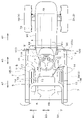
- FIG. 2 is a schematic plan view of the electric tractor 1.
- the electric tractor 1 is a tractor in which a traveling device 3 that supports the vehicle body 2 so as to be travelable is driven by an electric motor 4.
- the arrow A1 direction (forward direction of the electric tractor 1) of FIGS. 1 and 2 is forward
- the arrow A2 direction of FIGS. 1 and 2 reverse direction of the electric tractor 1
- the direction of arrow A3 of 2 will be described as the front-back direction. Therefore, the back side of FIG. 1 (direction of arrow B1 in FIG.
- the direction of arrow B3 in FIG. 2 will be described as the vehicle width direction (width direction of the electric tractor 1).
- the direction of the electric tractor 1 from the central portion in the vehicle width direction to the left or right will be described as the outward direction in the vehicle width direction. That is, the outside in the vehicle width direction is a direction away from the center of the electric tractor 1 in the vehicle width direction.
- the direction opposite to the outside in the vehicle width direction will be described as the inside in the vehicle width direction. That is, the inward direction in the vehicle width direction is a direction approaching the center of the electric tractor 1 in the vehicle width direction.
- the electric tractor 1 has a rops 5 as a driver protection device. That is, the electric tractor 1 is a type of electric tractor 1 that does not have a cabin surrounding the driver's seat 6. As shown in FIGS. 1 and 2, the electric tractor 1 has a vehicle body 2 movably supported by a traveling device 3.
- the traveling device 3 includes left and right front wheels 3A arranged at the front of the electric tractor 1 and left and right rear wheels 3B arranged at the rear of the electric tractor 1.
- the front wheels 3A are steered wheels (steering wheels).
- the rear wheel 3B is covered with a fender 7.
- the traveling device 3 is not limited to the wheel-type traveling device 3, and may be a crawler-type traveling device 3.
- the vehicle body 2 has an electric motor 4, a vehicle body frame 8, and a transmission case 9.
- the electric motor 4 is a power source for driving the traveling device 3.
- the electric motor 4 is arranged in front of the driver's seat 6 and the front control unit 11A, which will be described later, at the center of the electric tractor 1 in the vehicle width direction.
- the vehicle body frame 8 projects forward from the electric motor 4 and is supported by the left and right front wheels 3A.
- the transmission case 9 is spaced behind the electric motor 4 and is supported by the left and right rear wheels 3B.
- the transmission case 9 includes, for example, a mission case, a differential case, and the like.
- the transmission case 9 there is a transmission for shifting the rotational power transmitted from the electric motor 4 via the transmission shaft 15, a transmission mechanism for transmitting the power transmitted by the transmission to the rear wheels 3B, and the shifting. It houses a power take-out mechanism that takes out the power to be transmitted to the front wheels 3A.
- the electric motor 4, the vehicle body frame 8, and the transmission case 9 are connected to each other by a connecting frame (not shown).
- the electric motor 4 is arranged below the rear side of the battery 18, and the rear portion protrudes rearward from the battery 18.
- a connector (motor-side connector) 4A is provided on the front side of the electric motor 4.
- the motor-side connector 4A is a three-phase connector in this embodiment.
- the motor-side connector 4A is provided in the front lower portion (front side lower portion) of the electric motor 4.
- the inverter 19 is arranged between the battery 18 (battery support portion 24 described later) and the vehicle body frame 8 and in front of the electric motor 4.
- the inverter 19 is arranged so as to overlap with the electric motor 4 in the front-rear direction.
- the inverter 19 is arranged so that the inverter main body 19A overlaps the upper portion of the electric motor 4 in the front-rear direction.
- the inverter 19 is arranged below the front portion of the battery 18 so as to overlap the battery 18 in the vertical direction.
- a connector (inverter side connector) 19B connected to the motor side connector 4A by wiring (three-phase wiring, see FIG. 12) 21 is provided on the lower side of the inverter 19, a connector (inverter side connector) 19B connected to the motor side connector 4A by wiring (three-phase wiring, see FIG. 12) 21 is provided.
- the inverter side connector 19B is a three-phase connector in this embodiment.
- the inverter side connector 19B is provided on the lower surface side
- the electric tractor 1 has a support frame 22 attached to the vehicle body frame 8.
- a battery 18 and an inverter 19 are attached to and supported by the support frame 22.
- the vehicle body frame 8 mainly includes a first side plate 8A, a second side plate 8B, and a front plate 8C.
- the first side plate 8A and the second side plate 8B are arranged so that the plate surfaces face the vehicle width direction, and are arranged side by side at intervals in the vehicle width direction.
- the first side plate 8A projects forward from one side of the electric motor 4 in the vehicle width direction.
- the second side plate 8B extends forward from the other side in the vehicle width direction of the electric motor 4 and faces the first side plate 8A in the vehicle width direction.
- the front plate 8C is arranged so that the plate surface faces the front-rear direction, and is fixed to the front portions of the first side plate 8A and the second side plate 8B.
- the front plate 8C is provided from the front end of the first side plate 8A to the front end of the second side plate 8B, and connects the front end sides of the first side plate 8A and the second side plate 8B to each other.
- An open notch 8Ea is formed at the rear of the rear connecting plate 8E in order to prevent interference with the motor-side connector 4A of the electric motor 4.
- the reinforcing plate 8F is arranged on one end side of the rear connecting plate 8E and above the rear connecting plate 8E, and is fixed to the inside of the first side plate 8A.
- the reinforcing plate 8G is arranged on the other end side of the rear connecting plate 8E and above the rear connecting plate 8E, and is fixed to the inside of the second side plate 8B.
- the support frame 22 has a rear frame portion (frame member) 23, a battery support portion 24, and an inverter support portion 25.
- the rear frame portion 23 has a main frame 26, an upper frame 27, and a support portion 28.
- the main frame 26 has a first strut member 29, a second strut member 30, and a connecting frame body 31.
- the first support column member 29 constitutes one side of the main frame 26 in the vehicle width direction.
- the second support column member 30 constitutes the other side of the main frame 26 in the vehicle width direction.
- the connecting frame body 31 connects the first strut member 29 and the second strut member 30.
- the connecting frame body 31 includes a first vertical member 31A fixed to the front surface side of the first support column member 29, a second vertical member 31B fixed to the front surface side of the second support column member 30, and a first vertical member 31A. It has a first horizontal member 31C that connects the upper portions of the second vertical member 31B, and a second horizontal member 31D that connects the middle portions of the first vertical member 31A and the second vertical member 31B. As shown in FIG. 5, a regulating plate 32 including a regulating portion 32a projecting forward from the second strut member 30 is fixed to the upper portion of the second strut member 30.
- the mounting plate 33 is fixed to the upper part of the rear surface of the first support column member 29 and the upper part of the rear surface of the second support column member 30 so as to project rearward.
- the mounting plate 33 has a vertical plate portion 33a arranged so that the plate surface faces the vehicle width direction, and an extension plate portion 33b extending inward in the vehicle width direction from the upper end of the vertical plate portion 33a.
- the upper frame 27 is mounted on the first lateral member 31C.
- the upper frame 27 is provided with a support pin 34 in which the upper part on the back surface side of the bonnet 20 is rotatably supported around the axis extending in the vehicle width direction.
- the support portion 28 has a support plate 35 projecting forward from the lower part of the main frame 26, and support legs 36 provided on the lower surface side of the support plate 35.
- the support plate 35 has a main plate portion 35a arranged so that the plate surface faces in the vertical direction, and an extension plate portion 35b extending downward from the front end of the main plate portion 35a.
- the support plate 35 is arranged above the electric motor 4.
- Reinforcing plates 37 are fixed to the left and right of the lower surface of the main plate portion 35a.
- the support legs 36 are provided on the left and right sides of the lower surface side of the front portion of the support plate 35, respectively.
- the support legs 36 are fixed to the vehicle body frame 8. Specifically, the left support leg 36L is fixed to the rear upper end side of the first side plate 8A, and the right support leg 36R is fixed to the rear upper end side of the second side plate 8B.
- the rear portion of the support portion 28 (support plate 35) is supported on the vehicle body 2 side via the support member.
- the battery support portion 24 has a mounting plate 38 on which the battery 18 is mounted, and a mounting bracket 39 projecting downward from the mounting plate 38.
- the mounting plate 38 is mounted so that the plate surface faces in the vertical direction and is arranged above the electric motor 4 and the vehicle body frame 8, and the rear portion thereof is overlapped on the support plate 35. Therefore, the rear part of the mounting plate 38 (the rear part of the battery support part 24) is supported by the support part 28.
- the rear end side of the mounting plate 38 is attached to the support plate 35 by bolts or the like.
- a first side plate 41 extending in the front-rear direction is fixed to one side of the mounting plate 38 in the vehicle width direction, and the mounting plate 38 extends in the front-rear direction to the other side in the vehicle width direction.
- the second side plate 42 is fixed, the front plate 43 extending in the vehicle width direction is fixed to the front portion of the mounting plate 38, and the rear plate 44 extending in the vehicle width direction is fixed to the rear portion of the mounting plate 38. ..
- the middle portion of the plate surface in the vertical direction is fixed to the end portion of the mounting plate 38 and protrudes vertically from the mounting plate 38.
- the rear plate 44 is fixed to the upper surface of the mounting plate 38.
- the battery 18 mounted on the mounting plate 38 is restricted from moving backward by the rear plate 44, and is detachably attached to the first side plate 41, the second side plate 42, and the front plate 43 by bolts or the like. Further, the battery 18 is also fixed to the regulation portion 32a of the regulation plate 32 on the upper part of the second support column member 30 by a bolt or the like (see FIG. 3).
- a plurality of mounting brackets 39 are provided and are arranged on the lower side of the mounting plate 38.
- the plurality of mounting brackets 39 are the first bracket 39A arranged in the middle of the front-rear direction inside the first side plate 41, and the second bracket 39A arranged in the middle of the front-rear direction inside the second side plate 42. It includes a bracket 39B, a third bracket 39C arranged on the left side inside the front plate 43, and a fourth bracket 39D arranged on the right side inside the front plate 43.
- the first bracket 39A and the second bracket 39B are formed of channel steel
- the third bracket 39C and the fourth bracket 39D are formed of angle steel. It is not limited to this.
- the first bracket 39A to the fourth bracket 39D are attached to the first side plate 41, the second side plate 42, and the front plate 43 via the mounting frame 45.
- the mounting frame 45 includes a first plate material 45A attached to the inside of the first side plate 41 by bolts or the like, a second plate material 45B attached to the inside of the second side plate 42 by bolts or the like, and a bolt or the like inside the front plate 43. It has a third plate material 45C to be attached.
- the first bracket 39A is fixed to the rear part of the first plate material 45A
- the second bracket 39B is fixed to the rear part of the second plate material 45B
- the third bracket 39C is fixed to the left part of the third plate material 45C
- the fourth bracket 39D Is fixed to the right part of the third plate material 45C.
- the inverter support portion 25 is arranged below the front portion of the mounting plate 38 and is fixed to the vehicle body frame 8 to support the front portion of the mounting plate 38.
- the inverter support portion 25 has a support plate 46 and a support stay 47 projecting upward from the support plate 46.
- the support plates 46 are spaced apart below the mounting plate 38 (see FIG. 3). Further, the support plate 46 is arranged so that the plate surface faces in the vertical direction, and is provided over the upper end of the first side plate 8A and the upper end of the second side plate 8B.
- An open notch 46a is formed in front of the front portion of the support plate 46.
- An open notch 46b is formed at the rear of the support plate 46.
- the left portion of the support plate 46 projects to the left from the first side plate 8A.
- the right portion of the support plate 46 projects to the right from the second side plate 8B.
- the fixture 48 is fixed to the front portion and the rear portion on the lower surface side of the protruding portion on the right side of the support plate 46.
- a similar attachment 48 is fixed to the lower surface side of the protruding portion on the left side of the support plate 46.
- the attachment 48 on the left side of the support plate 46 is attached to the first side plate 8A by bolts or the like, and the attachment 48 on the right side of the support plate 46 is attached to the second side plate 8B by bolts or the like.
- the inverter support portion 25 is attached to the vehicle body frame 8.
- the plurality of support stays 47 include a first stay 47A, a second stay 47B, a third stay 47C, and a fourth stay 47D.
- the first stay 47A and the second stay 47B are formed of channel steel
- the third stay 47C and the fourth stay 47D are formed of angle steel. It is not limited to this.
- the first stay 47A is fixed to the rear portion of the left portion of the support plate 46 at a position corresponding to the fixture 48.
- the second stay 47B is fixed to the rear portion of the right side of the support plate 46 and at a position corresponding to the fixture 48.
- the third stay 47C is a front portion on the left side of the support plate 46 and is fixed at a position corresponding to the fixture 48.
- the fourth stay 47D is a front portion on the right side of the support plate 46 and is fixed at a position corresponding to the fixture 48.
- the first bracket 39A is attached to the first stay 47A
- the second bracket 39B is attached to the second stay 47B
- the third bracket 39C is attached to the third stay 47C
- the fourth bracket 39D is attached to the fourth stay 47D. (See FIGS. 3, 4, and 5).
- the battery support portion 24 is attached to the inverter support portion 25 so that a space in which the inverter 19 can be arranged is formed between the mounting plate 38 and the support plate 46.
- the motor-side connector 4A and the inverter-side connector 19B are arranged between the first side plate 8A and the second side plate 8B. According to this configuration, the motor side connector 4A, the inverter side connector 19B, and the wiring 21 can be protected by the first side plate 8A and the second side plate 8B. Further, it is possible to prevent the motor side connector 4A, the inverter side connector 19B and the wiring 21 from being damaged, and it is possible to improve the reliability.
- the wiring connection port of the motor-side connector 4A faces forward, and the wiring connection port of the inverter-side connector 19B faces rearward. That is, the motor-side connector 4A and the inverter-side connector 19B face each other in the front-rear direction. Further, the motor-side connector 4A and the inverter-side connector 19B are arranged so as to overlap each other in the front-rear direction. Therefore, the motor-side connector 4A and the inverter-side connector 19B can be connected by a short route, the heat generation of the wiring 21 can be suppressed, and the efficiency of the system can be improved. Further, by shortening the wiring 21, the cost can be reduced. Further, since the wiring 21 is short and bending can be eliminated as much as possible, the possibility that the wiring 21 is damaged by an external factor can be reduced, and the reliability can be improved.
- the water pump 94 is attached to the front connecting plates 8D and 8E of the vehicle body frame 8.
- the water pump 94 is a pump that circulates cooling water that cools the electric motor 4, the inverter 19, the voltage converter described later, and the like.
- a hydraulic pump P1 driven by the electric motor 4 is arranged on the side of the electric motor 4.
- the hydraulic pump P1 sucks the oil in the transmission case 9 and supplies the oil as hydraulic oil to each hydraulic drive unit.
- a power transmission mechanism 49 is provided on the rear surface side of the electric motor 4 and the hydraulic pump P1, and power is transmitted from the electric motor 4 to the hydraulic pump P1 by the power transmission mechanism 49.
- the power transmission mechanism 49 is covered with a cover case 61.
- the cover case 61 is formed so as to be open to the front.
- the power transmission mechanism 49 is configured by a gear transmission mechanism.
- the power transmission mechanism 49 is arranged between the output gear 51 connected to the output shaft of the electric motor 4 and rotating, the input gear 52 connected to the input shaft of the hydraulic pump P1, and the output gear 51 and the input gear 52. It has one or more transmission gears 53 that transmit power from the output gear 51 to the input gear 52.
- the output gear 51, the input gear 52, and the transmission gear 53 are formed by spur gears and rotate around an axial center extending in the front-rear direction. It is not limited to this.
- the radiator R1, the voltage converter (DCDC converter) C1, the auxiliary battery BT, and the reserve tank R2 are located in front of the battery support portion 24 and in front of the vehicle body frame 8.
- a cooling fan device F1, an oil cooler O1 and the like are attached and supported.
- the radiator R1, the voltage converter C1, and the auxiliary battery BT are arranged side by side in the vehicle width direction in order from the left.
- the reserve tank R2 is arranged above the auxiliary battery BT.
- the cooling fan device F1 is arranged behind the radiator R1, and the oil cooler O1 is arranged behind the cooling fan device F1.
- the radiator R1 is a radiator that cools the cooling water circulated by the water pump 94 by the cooling air generated by the cooling fan device F1.
- the voltage converter C1 is a device that steps down the electric power sent from the battery 18 and supplies it to the auxiliary battery BT.
- the auxiliary battery BT is a storage battery that supplies electric power to various electric devices such as a cooling fan device F1, a control device for controlling electric devices such as an inverter 19 and an electric motor 4, and a lamp.
- the reserve tank R2 is a tank for storing cooling water that escapes from the radiator R1 at a high temperature.
- the oil cooler O1 is a radiator that cools the hydraulic oil that operates the hydraulic equipment and the like by the cooling air generated by the cooling fan device F1.
- a charging connector 90 for charging the battery 18 is provided in the front control unit 11A of the driving unit 10.
- the front control unit 11A has a steering operation device 91 including a steering handle 12, and a front cover (cover body) 92 that covers the lower side of the steering operation device 91.
- the front cover (front control unit 11A) 92 is arranged above the vehicle body 2 and mounted on the vehicle body. That is, the front cover 92 is erected on the vehicle body 2. Further, the front cover 92 is provided so as to project upward from the floor 16.
- the steering handle 12 is arranged on the upper part of the back surface of the front cover 92.
- An instrument panel 54 having a monitor, various meters, various switches, and the like is provided on the upper portion of the front cover 92.
- the instrument panel 54 is provided with a battery fuel gauge that displays the amount of charge of the battery 18.
- the front cover 92 is arranged behind the bonnet 20 in the vicinity of the bonnet 20, and is formed in an open shape in the front. Further, the rear end of the bonnet 20 is open to the rear. Therefore, the front cover 92 and the bonnet 20 communicate with each other. Further, the rear frame portion 23 (main frame 26) of the support frame 22 is arranged on the rear end side of the bonnet 20, and the mounting plate 33 provided on the rear frame portion 23 is inserted into the front cover 92. Has been done.
- the steering operation device 91 includes a steering operation member (operation member) 86 including a steering handle 12 and a steering shaft 56, a steering post 57 that supports the steering shaft 56, and a universal joint 62 to the steering shaft 56. It includes a steering valve 58 connected via the steering post 57, and a frame member 59 that supports the steering post 57, the steering valve 58, and the like. Therefore, the front cover 92 covers the lower side of the steering operation member 86.
- the frame member 59 is attached and supported by a member attached to the vehicle body 2 side such as the rear frame portion 23.
- the steering valve 58 is operated via the steering shaft 56 and the universal joint 62, and the steering valve 58 uses the hydraulic oil supplied from the hydraulic pump P1. It is supplied to the steering cylinder (not shown) that steers the front wheel 3A.
- the charging connector 90 is arranged on the outer surface side of the front cover 92 (cover body) and is exposed to the outside of the front cover 92 (front control portion 11A). ing. Further, the charging connector 90 is arranged on the side surface side (right side surface side) of the front cover 92 so as to face outward (right side) in the vehicle width direction. Further, as shown in FIG.
- the charging connector 90 is arranged in front of and below the steering handle 12. Furthermore, as shown in FIG. 1, the charging connector 90 is located on the upper part of the outer surface of the front cover 92 at substantially the same height as the seat portion 6A of the driver's seat 6. The right side of the front cover 92 is open so that the floor 16 below the charging connector 90 can be rested on when charging. A passable space is formed between the front cover 92 and the fender 7.
- the charging connector 90 has a connector main body 96 having a connection terminal portion 96a, a cap 97 for opening and closing the connection terminal portion 96a side of the connector main body 96 so as to be openable, and a wiring terminal portion 96b. are doing.
- the connection terminal 96a is a portion to which a power supply connector 64 installed in an external power supply facility such as a charging station, a charging facility called a charging station, or a charging facility installed in a house is connected.
- the connector main body 96 is arranged outside the vehicle width direction (right side) of the steering wheel 12 and outside the vehicle width direction of the driver's seat 6. As shown in FIG. 17, the cap 97 is attached to the connector main body 96 so that the pivot portion 97a provided at the front portion rotates about the vertical axis (the axial center extending in the vertical direction). Behind the cap 97, a locking tool 98 that engages with and detachably engages with the cap 97 to regulate the opening operation of the cap 97 is provided. The locking tool 98 is pivotally supported by the connector main body 96, and the restriction on the opening operation of the cap 97 can be released by rotating the locking tool 98 around the vertical axis. By opening the cap 97 forward around the vertical axis and operating the cap 97, the connection terminal portion 96a of the connector main body 96 can be exposed to the outer side in the vehicle width direction.
- the wiring terminal portion 96b protrudes from the back surface of the connector main body 96 and is inserted into the front cover 92.
- the wiring terminal portion 96b is a portion to which the connection wiring connecting the charging connector 90 and the battery 18 is connected.
- an indicator lamp 101 and a side mirror 100 are arranged on the front side of the charging connector 90.
- the indicator lamp 101 is, for example, a combination lamp configured by combining a plurality of lamps.
- the lamps constituting the combination lamp are a position lamp, a turn signal lamp, a hazard lamp and the like.
- the side mirror 100 is a mirror that visually recognizes the rear side of the vehicle body 2.
- the mirror body 100a of the indicator lamp 101 and the side mirror 100 is located in front of the charging connector 90 and outside the charging connector 90 in the vehicle width direction.
- the charging connector 90 is attached to the connector bracket 93.
- the connector bracket 93 has a first bracket member 66 and a second bracket member 67.
- the first bracket member 66 is mounted on the vertical plate portion 33a of the mounting plate (mounting portion) 33 provided on the rear frame portion 23 so as to be overlapped with the mounting wall portion 66a, and the first bracket member 66 is outside the vehicle width direction from the front end of the mounting wall portion 66a.
- the extending wall portion 66b extending in the direction, the lamp mounting portion 66c extending rearward from the extending end (the end on the outer side in the vehicle width direction) of the extending wall portion 66b, the mounting wall portion 66a, and the lamp mounting portion 66c.
- the extending wall portion 66b protrudes outward in the vehicle width direction from the inner side of the front cover 92, and a mounting hole 68 is formed in the protruding portion of the extending wall portion 66b.
- the connector bracket 93 has a connector mounting portion (second member 72) to which the charging connector 90 is mounted outside the front cover 92 and a mounting portion (mounting plate 33) provided on the inner side of the front cover 92. ) With a mounting wall portion 66a.
- the support column member 73 of the side mirror 100 is attached to the upper part of the first member 71 of the second bracket member 67 via the attachment 74. Therefore, the upper part of the first member 71 is a mirror mounting portion 75 to which the side mirror 100 is mounted.
- the lamp stay 76 of the indicator lamp 101 is attached to the lamp mounting portion 66c of the first bracket member 66.
- the connector bracket 93 has a mirror mounting portion 75 to which the side mirror 100 is mounted and a lamp mounting portion 66c to which the indicator lamp 101 is mounted.
- the charging connector 90 can also be arranged on the outer surface side of the cover body 14 of the side control portion 11B. That is, the charging connector 90 is a cover body provided around the driver's seat 6, and is provided on the cover body that covers the lower side of the operating member.
- the electric motor 4 for driving the traveling device 3 the battery 18, the inverter 19 for supplying the electric power from the battery 18 to the electric motor 4, and the driver's seat 6 are arranged in front of the electric motor 4.
- a vehicle body frame 8 arranged below the bonnet 20 covering the battery 18 and a support frame 22 attached to the vehicle body frame 8 are provided, and the support frame 22 is arranged above the electric motor 4 and above the vehicle body frame 8. It has a battery support portion 24 that supports the battery 18 and an inverter support portion 25 that supports the inverter 19 arranged between the battery support portion 24 and the vehicle body frame 8 and in front of the electric motor 4. .
- the battery support portion 24 that supports the battery 18 arranged above the electric motor 4 and above the vehicle body frame 8, between the battery support portion 24 and the vehicle body frame 8, and in front of the electric motor 4.
- the inverter support portion 25 that supports the inverter 19 arranged in the above, the electric motor 4 and the inverter 19 can be arranged at close positions, and the electric motor 4 and the inverter 19 can be connected by a short path.
Landscapes
- Engineering & Computer Science (AREA)
- Transportation (AREA)
- Mechanical Engineering (AREA)
- Chemical & Material Sciences (AREA)
- Combustion & Propulsion (AREA)
- Power Engineering (AREA)
- Life Sciences & Earth Sciences (AREA)
- Sustainable Development (AREA)
- Sustainable Energy (AREA)
- Arrangement Or Mounting Of Propulsion Units For Vehicles (AREA)
- Electric Propulsion And Braking For Vehicles (AREA)
Abstract
電動トラクタは、走行装置(3)を駆動する電動モータ(4)と、バッテリ(18)と、バッテリ(18)からの電力を電動モータ(4)へ供給するインバータ(19)と、運転席(6)の前方に配置されてバッテリ(18)を覆うボンネット(20)の下方に配置された車体フレーム(8)と、車体フレーム(8)に取り付けられた支持フレーム(22)と、を備え、支持フレーム(22)は、電動モータ(4)の上方且つ車体フレーム(8)の上方に配置されたバッテリ(18)を支持するバッテリ支持部(24)と、バッテリ支持部(24)と車体フレーム(8)との間で且つ電動モータ(4)の前方に配置されたインバータ(19)を支持するインバータ支持部(25)とを有している。
Description
本発明は、電動トラクタに関する。
従来、特許文献1、特許文献2に開示された電動トラクタが知られている。
特許文献1に開示された電動トラクタは、車体を走行可能に支持する走行装置を電動モータによって駆動するトラクタである。電動トラクタには、電動モータに電力を供給するバッテリと、バッテリからの直流電力を交流電力に変換して電動モータへ供給するインバータとが設けられる。
特許文献1に開示された電動トラクタは、車体を走行可能に支持する走行装置を電動モータによって駆動するトラクタである。電動トラクタには、電動モータに電力を供給するバッテリと、バッテリからの直流電力を交流電力に変換して電動モータへ供給するインバータとが設けられる。
特許文献2に開示された電動トラクタには、電動モータに電力を供給するバッテリと、このバッテリの充電を行うための充電用コネクタとが設けられる。充電用コネクタに、外部電源設備に装備された給電用コネクタを接続することでバッテリに充電することができる。
ところで、電動モータとインバータとを接続する配線には大きな電流が流れるため、該配線の長さが長い場合(特許文献1参照)、電線の損失による発熱及び効率低下が懸念される。それ故、電動モータ・インバータ間は、できるだけ短い経路で繋ぐことが重要である。
また、特許文献2に開示の電動トラクタは、スタータキーが差し込まれるキーシリンダを有するシリンダホルダの奥に、充電用コネクタが設けられているので、バッテリの充電を行うのが面倒である。
また、特許文献2に開示の電動トラクタは、スタータキーが差し込まれるキーシリンダを有するシリンダホルダの奥に、充電用コネクタが設けられているので、バッテリの充電を行うのが面倒である。
本発明は、上記問題点に鑑み、電動モータとインバータとを短い経路で繋ぐことができる電動トラクタを提供することを目的とする。
また、本発明は、運転部に充電用コネクタが設けられた電動トラクタにおいて、バッテリの充電を容易に行うことができる電動トラクタを提供することを目的とする。
また、本発明は、運転部に充電用コネクタが設けられた電動トラクタにおいて、バッテリの充電を容易に行うことができる電動トラクタを提供することを目的とする。
本発明の一態様に係る電動トラクタは、走行装置を駆動する電動モータと、バッテリと、前記バッテリからの電力を前記電動モータへ供給するインバータと、運転席の前方に配置されて前記バッテリを覆うボンネットの下方に配置された車体フレームと、前記車体フレームに取り付けられた支持フレームと、を備え、前記支持フレームは、前記電動モータの上方且つ前記車体フレームの上方に配置された前記バッテリを支持するバッテリ支持部と、前記バッテリ支持部と前記車体フレームとの間で且つ前記電動モータの前方に配置された前記インバータを支持するインバータ支持部とを有している。
また、前記バッテリ支持部は、前記バッテリが載置される載置プレートと、前記載置プレートから下方に突出する取付ブラケットとを有し、前記インバータ支持部は、前記インバータが載置される支持プレートであって前記載置プレートの下方に間隔をあけて配置され且つ前記車体フレームに取り付けられる支持プレートと、前記支持プレートから上方に突出すると共に前記取付ブラケットが取り付けられる支持ステーとを有している。
また、前記インバータ支持部は、前記インバータが前記電動モータと前後方向でオーバーラップして配置されるように前記インバータを支持する。
また、前記支持フレームは、前記載置プレートの後部下方に配置されたサポート部であって前記車体フレームに固定されて前記載置プレートの後部を支持するサポート部を有し、前記インバータ支持部は、前記載置プレートの前部を支持する。
また、前記支持フレームは、前記載置プレートの後部下方に配置されたサポート部であって前記車体フレームに固定されて前記載置プレートの後部を支持するサポート部を有し、前記インバータ支持部は、前記載置プレートの前部を支持する。
また、前記サポート部は、前記載置プレートの後部が載置されるサポートプレートであって前記電動モータの上方に配置されたサポートプレートと、前記サポートプレートの下面側に設けられていて前記車体フレームに固定された支持脚とを有している。
また、前記電動モータは、当該電動モータの前部側に設けられたモータ側コネクタを有し、前記インバータは、前記モータ側コネクタに接続されるインバータ側コネクタであって前記モータ側コネクタの前方に配置されたインバータ側コネクタを有している。
また、前記電動モータは、当該電動モータの前部側に設けられたモータ側コネクタを有し、前記インバータは、前記モータ側コネクタに接続されるインバータ側コネクタであって前記モータ側コネクタの前方に配置されたインバータ側コネクタを有している。
また、前記モータ側コネクタは、前記電動モータの前下部に設けられ、前記インバータは、前記インバータ支持部に載置されて支持されるインバータ本体が前記電動モータの上部の後方に前後方向でオーバーラップするように配置され、前記インバータ側コネクタは、前記インバータ本体の下部側に設けられていて前記インバータ支持部から下方に突出している。
また、前記インバータ支持部は、前記インバータ側コネクタを前記インバータ支持部から下方に突出させる切り欠き部を有している。
また、前記車体フレームは、車幅方向で間隔をあけて並べて配置された第1サイドプレート及び第2サイドプレートを有し、前記モータ側コネクタ及び前記インバータ側コネクタは、前記第1サイドプレートと前記第2サイドプレートとの間に配置されている。
また、前記車体フレームは、車幅方向で間隔をあけて並べて配置された第1サイドプレート及び第2サイドプレートを有し、前記モータ側コネクタ及び前記インバータ側コネクタは、前記第1サイドプレートと前記第2サイドプレートとの間に配置されている。
本発明の他の態様に係る電動トラクタは、運転席及び前記運転席の周囲に設けられた操縦部を含む運転部と、前記運転部が搭載された車体と、前記車体を走行可能に支持する走行装置と、前記走行装置を駆動する電動モータと、前記電動モータに電力を供給するバッテリと、前記バッテリの充電を行うための充電用コネクタと、を備え、前記操縦部は、操作部材と、前記操作部材の下部側を覆うカバー体とを含み、前記充電用コネクタは、前記カバー体の外面側に前記操縦部の外方に露出して配置されている。
また、前記充電用コネクタは、前記カバー体の側面側に車幅方向外方を向くように配置されている。
また、前記操縦部は、前記運転席の前方に配置された前記操作部材としてのステアリング操作部材と、前記ステアリング操作部材の下部側を覆う前記カバー体としてのフロントカバーとを含み、前記充電用コネクタは、前記フロントカバーの外側面の上部に配置されている。
また、前記操縦部は、前記運転席の前方に配置された前記操作部材としてのステアリング操作部材と、前記ステアリング操作部材の下部側を覆う前記カバー体としてのフロントカバーとを含み、前記充電用コネクタは、前記フロントカバーの外側面の上部に配置されている。
また、前記ステアリング操作部材は、ステアリングハンドルを含み、前記充電用コネクタは、前記ステアリングハンドルよりも前方に配置されている。
また、前記充電用コネクタは、前記フロントカバーの外側面における前記運転席の座部と略同じ高さ位置に配置されている。
また、前記充電用コネクタが取り付けられるコネクタブラケットを備え、前記コネクタブラケットは、前記フロントカバーの外部で充電用コネクタが取り付けられるコネクタ取付部と、前記フロントカバーの内部側に設けられた取付部に取り付けられる取付壁部とを有している。
また、前記充電用コネクタは、前記フロントカバーの外側面における前記運転席の座部と略同じ高さ位置に配置されている。
また、前記充電用コネクタが取り付けられるコネクタブラケットを備え、前記コネクタブラケットは、前記フロントカバーの外部で充電用コネクタが取り付けられるコネクタ取付部と、前記フロントカバーの内部側に設けられた取付部に取り付けられる取付壁部とを有している。
また、前記コネクタブラケットは、サイドミラーが取り付けられるミラー取付部を有している。
また、前記コネクタブラケットは、表示ランプが取り付けられるランプ取付部を有している。
また、前記コネクタブラケットは、表示ランプが取り付けられるランプ取付部を有している。
上記の電動トラクタによれば、電動モータの上方且つ車体フレームの上方に配置されたバッテリを支持するバッテリ支持部と、バッテリ支持部と車体フレームとの間で且つ電動モータの前方に配置されたインバータを支持するインバータ支持部とを設けることで、電動モータとインバータとを近い位置に配置でき、電動モータとインバータとを短い経路で繋ぐことができる。
また、上記の電動トラクタによれば、走行用の電動モータに電力を供給するバッテリの充電を行うための充電用コネクタが操縦部のカバー体の外面側に該操縦部の外方に露出して配置されているので、バッテリの充電を容易に行うことができる。
以下、本発明の一実施形態について、図面を適宜参照しつつ説明する。
図1は、本実施形態に係る電動トラクタ1の全体構成を示す概略側面図である。図2は、電動トラクタ1の概略平面図である。電動トラクタ1は、車体2を走行可能に支持する走行装置3を電動モータ4によって駆動するトラクタである。
本実施形態においては、図1、図2の矢印A1方向(電動トラクタ1の前進方向)を前方、図1、図2の矢印A2方向(電動トラクタ1の後進方向)を後方、図1、図2の矢印A3方向を前後方向として説明する。したがって、図1の奥側(図2の矢印B1方向)が左方であり、図1の手前側(図2の矢印B2方向)が右方である。また、図2の矢印B3方向を車幅方向(電動トラクタ1の幅方向)として説明する。電動トラクタ1における車幅方向の中央部から左方或いは右方に向かう方向を車幅方向外方として説明する。つまり、車幅方向外方とは、電動トラクタ1の中心から車幅方向に離れる方向である。また、車幅方向外方とは反対の方向を車幅方向内方として説明する。つまり、車幅方向内方とは、車幅方向において電動トラクタ1の中心に近づく方向である。
図1は、本実施形態に係る電動トラクタ1の全体構成を示す概略側面図である。図2は、電動トラクタ1の概略平面図である。電動トラクタ1は、車体2を走行可能に支持する走行装置3を電動モータ4によって駆動するトラクタである。
本実施形態においては、図1、図2の矢印A1方向(電動トラクタ1の前進方向)を前方、図1、図2の矢印A2方向(電動トラクタ1の後進方向)を後方、図1、図2の矢印A3方向を前後方向として説明する。したがって、図1の奥側(図2の矢印B1方向)が左方であり、図1の手前側(図2の矢印B2方向)が右方である。また、図2の矢印B3方向を車幅方向(電動トラクタ1の幅方向)として説明する。電動トラクタ1における車幅方向の中央部から左方或いは右方に向かう方向を車幅方向外方として説明する。つまり、車幅方向外方とは、電動トラクタ1の中心から車幅方向に離れる方向である。また、車幅方向外方とは反対の方向を車幅方向内方として説明する。つまり、車幅方向内方とは、車幅方向において電動トラクタ1の中心に近づく方向である。
図1、図2に示すように、電動トラクタ1は、運転者保護装置として、ロプス5を有している。つまり、電動トラクタ1は、運転席6を包囲するキャビンを有していないタイプの電動トラクタ1である。
図1、図2に示すように、電動トラクタ1は、走行装置3によって走行可能に支持される車体2を有している。走行装置3は、電動トラクタ1の前部に配置された左及び右の前輪3A、電動トラクタ1の後部に配置された左及び右の後輪3Bを有して構成されている。前輪3Aは、操向輪(操舵輪)とされている。後輪3Bは、フェンダ7によって覆われている。なお、走行装置3としては、車輪型の走行装置3に限定されることはなく、クローラ型の走行装置3であってもよい。
図1、図2に示すように、電動トラクタ1は、走行装置3によって走行可能に支持される車体2を有している。走行装置3は、電動トラクタ1の前部に配置された左及び右の前輪3A、電動トラクタ1の後部に配置された左及び右の後輪3Bを有して構成されている。前輪3Aは、操向輪(操舵輪)とされている。後輪3Bは、フェンダ7によって覆われている。なお、走行装置3としては、車輪型の走行装置3に限定されることはなく、クローラ型の走行装置3であってもよい。
図1に示すように、車体2は、電動モータ4と、車体フレーム8と、伝動ケース9とを有している。電動モータ4は、走行装置3を駆動する動力源である。電動モータ4は、運転席6及び後述する前部操縦部11Aの前方で電動トラクタ1の車幅方向中央部に配置されている。車体フレーム8は、電動モータ4から前方に突出しており、左及び右の前輪3Aによって支持されている。伝動ケース9は、電動モータ4の後方に間隔をあけて配置されていて、左及び右の後輪3Bによって支持されている。伝動ケース9は、例えば、ミッションケース、デフケース等を有して構成される。伝動ケース9内には、電動モータ4から伝動軸15を介して伝達される回転動力を変速する変速装置や、該変速装置によって変速された動力を後輪3Bに伝達する伝動機構及び該変速された動力を前輪3Aへ伝達すべく取り出す動力取出し機構等が収容されている。電動モータ4、車体フレーム8及び伝動ケース9は、図示省略の連結フレームによって相互に連結されている。
なお、伝動ケース9の後部には、作業機を着脱可能に連結する三点リンク機構等の装着機構(図示省略)や、該装着機構(作業機)を上げ下げする油圧機構が装備される。
車体2には、運転席6及び運転席6の周囲を含む運転部10が搭載されている。運転部10の周囲は開放されている。運転席6は、伝動ケース9の上方に配置され、該伝動ケース9に支持されている。運転席6は、オペレータが着座する座部6Aと、座部6Aの後部から上方に突出していてオペレータの背中を支持する背もたれ部6Bとを有している。運転部10は、運転席6の前方に配置された操縦部(前部操縦部)11A及び運転席6の左方及び右方に配置された操縦部(側部操縦部)11Bを有している。
車体2には、運転席6及び運転席6の周囲を含む運転部10が搭載されている。運転部10の周囲は開放されている。運転席6は、伝動ケース9の上方に配置され、該伝動ケース9に支持されている。運転席6は、オペレータが着座する座部6Aと、座部6Aの後部から上方に突出していてオペレータの背中を支持する背もたれ部6Bとを有している。運転部10は、運転席6の前方に配置された操縦部(前部操縦部)11A及び運転席6の左方及び右方に配置された操縦部(側部操縦部)11Bを有している。
前部操縦部11Aは、左及び右の前輪3Aを操向操作するステアリングハンドル12を含む。側部操縦部11Bは、操作レバー(操作部材)13と、該操作レバー13の下部側を覆うカバー体14とを有している。操作レバー13としては、例えば、変速装置の副変速機構を変速する副変速レバー、電動トラクタ1の後方に装着される作業機に動力を伝達するPTO軸を操作するPTOレバー、上記作業機の上下方向の位置を設定するポジションレバー、上記作業機を操作するホジョコントロールレバー等である。
運転席6の前方且つ下方には、オペレータの足を置くフロア16が設けられている。フロア16の右部には、走行装置3の変速を行うための変速ペダル17が配置されている。
図1、図2に示すように、電動トラクタ1は、電動モータ4に電力を供給するバッテリ18と、バッテリ18からの直流電力を交流電力に変換して電動モータ4へ供給するインバータ19とを備えている。バッテリ18は、走行用のバッテリ18である。
図1、図2に示すように、電動トラクタ1は、電動モータ4に電力を供給するバッテリ18と、バッテリ18からの直流電力を交流電力に変換して電動モータ4へ供給するインバータ19とを備えている。バッテリ18は、走行用のバッテリ18である。
図1~図4に示すように、バッテリ18は、電動モータ4の上方且つ車体フレーム8の上方に配置されている。詳しくは、バッテリ18は、電動モータ4及び車体フレーム8の上方に、電動モータ4及び車体フレーム8と上下方向で(平面視で)オーバーラップするように配置されている。バッテリ18は、運転席6の前方に配置された開閉可能なボンネット20によって覆われている。ボンネット20の下方に車体フレーム8が配置されている。
図2に示すように、電動モータ4は、バッテリ18の後部側の下方に配置され、後部がバッテリ18よりも後方に突出している。図3に示すように、電動モータ4の前部側には、コネクタ(モータ側コネクタ)4Aが設けられている。モータ側コネクタ4Aは、本実施形態では、三相コネクタである。モータ側コネクタ4Aは、電動モータ4の前下部(前面側下部)に設けられている。
図3に示すように、インバータ19は、バッテリ18(後述するバッテリ支持部24)と車体フレーム8との間で且つ電動モータ4の前方に配置されている。インバータ19は、電動モータ4と前後方向でオーバーラップするように配置されている。詳しくは、インバータ19は、インバータ本体19Aが電動モータ4の上部と前後方向でオーバーラップするように配置されている。また、インバータ19は、バッテリ18の前部の下方にバッテリ18と上下方向でオーバーラップするように配置されている。インバータ19の下部側には、モータ側コネクタ4Aに配線(三相配線、図12参照)21によって接続されるコネクタ(インバータ側コネクタ)19Bが設けられている。インバータ側コネクタ19Bは、本実施形態では、三相コネクタである。インバータ側コネクタ19Bは、インバータ19の後部の下面側に設けられ、インバータ本体19Aから下方に突出している。
図3、図4、図5に示すように、電動トラクタ1は、前記車体フレーム8に取り付けられた支持フレーム22を有している。この支持フレーム22にバッテリ18及びインバータ19が取り付けられて支持されている。
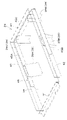
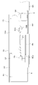
図6に示すように、車体フレーム8は、第1サイドプレート8Aと、第2サイドプレート8Bと、フロントプレート8Cとを有して主構成されている。第1サイドプレート8A及び第2サイドプレート8Bは、板面が車幅方向を向くように配置され、車幅方向で間隔をあけて並べて配置されている。
図6に示すように、車体フレーム8は、第1サイドプレート8Aと、第2サイドプレート8Bと、フロントプレート8Cとを有して主構成されている。第1サイドプレート8A及び第2サイドプレート8Bは、板面が車幅方向を向くように配置され、車幅方向で間隔をあけて並べて配置されている。
図4に示すように、第1サイドプレート8Aは、電動モータ4の車幅方向の一側から前方に突出している。第2サイドプレート8Bは、電動モータ4の車幅方向の他側から前方に延出されていて第1サイドプレート8Aに車幅方向で対向している。
フロントプレート8Cは、板面が前後方向を向くように配置され、第1サイドプレート8A及び第2サイドプレート8Bの前部に固定されている。詳しくは、フロントプレート8Cは、第1サイドプレート8Aの前端から第2サイドプレート8Bの前端にわたって設けられ、第1サイドプレート8Aと第2サイドプレート8Bの前端側同士を連結している。
フロントプレート8Cは、板面が前後方向を向くように配置され、第1サイドプレート8A及び第2サイドプレート8Bの前部に固定されている。詳しくは、フロントプレート8Cは、第1サイドプレート8Aの前端から第2サイドプレート8Bの前端にわたって設けられ、第1サイドプレート8Aと第2サイドプレート8Bの前端側同士を連結している。
また、車体フレーム8は、連結プレート8D,8Eと、補強プレート8F,8Gを有している。連結プレート8D,8Eは、複数枚設けられ、複数枚の連結プレートは、前連結プレート8Dと、後連結プレート8Eとを含む。前連結プレート8Dは、板面が上下方向を向くように配置されて、フロントプレート8Cの後方で第1サイドプレート8Aと第2サイドプレート8Bの前部の下端側同士を連結している。後連結プレート8Eは、板面が上下方向を向くように配置されて、前連結プレート8Dの後方で、第1サイドプレート8Aと第2サイドプレート8Bの上下方向中途部同士を連結している。後連結プレート8Eの後部には、電動モータ4のモータ側コネクタ4Aとの干渉を防止するために、後方に開放状の切り欠き部8Eaが形成されている。補強プレート8Fは、後連結プレート8Eの一端側で且つ後連結プレート8Eよりも上方に配置され、第1サイドプレート8Aの内側に固定されている。補強プレート8Gは、後連結プレート8Eの他端側で且つ後連結プレート8Eよりも上方に配置され、第2サイドプレート8Bの内側に固定されている。
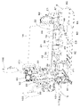
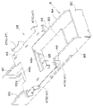
図5に示すように、支持フレーム22は、リヤフレーム部(フレーム部材)23と、バッテリ支持部24と、インバータ支持部25とを有している。
図6、図7に示すように、リヤフレーム部23は、メインフレーム26と、上部フレーム27と、サポート部28とを有している。
メインフレーム26は、第1支柱部材29、第2支柱部材30及び連結枠体31を有している。第1支柱部材29は、メインフレーム26の車幅方向の一側を構成する。第2支柱部材30は、メインフレーム26の車幅方向の他側を構成する。連結枠体31は、第1支柱部材29と第2支柱部材30とを連結する。連結枠体31は、第1支柱部材29の前面側に固定された第1縦部材31Aと、第2支柱部材30の前面側に固定された第2縦部材31Bと、第1縦部材31Aと第2縦部材31Bの上部同士を連結する第1横部材31Cと、第1縦部材31Aと第2縦部材31Bの中途部同士を連結する第2横部材31Dとを有している。図5に示すように、第2支柱部材30の上部には、第2支柱部材30から前方に突出する規制部32aを含む規制板32が固定されている。
図6、図7に示すように、リヤフレーム部23は、メインフレーム26と、上部フレーム27と、サポート部28とを有している。
メインフレーム26は、第1支柱部材29、第2支柱部材30及び連結枠体31を有している。第1支柱部材29は、メインフレーム26の車幅方向の一側を構成する。第2支柱部材30は、メインフレーム26の車幅方向の他側を構成する。連結枠体31は、第1支柱部材29と第2支柱部材30とを連結する。連結枠体31は、第1支柱部材29の前面側に固定された第1縦部材31Aと、第2支柱部材30の前面側に固定された第2縦部材31Bと、第1縦部材31Aと第2縦部材31Bの上部同士を連結する第1横部材31Cと、第1縦部材31Aと第2縦部材31Bの中途部同士を連結する第2横部材31Dとを有している。図5に示すように、第2支柱部材30の上部には、第2支柱部材30から前方に突出する規制部32aを含む規制板32が固定されている。
図7に示すように、第1支柱部材29の後面上部及び第2支柱部材30の後面上部には、取付プレート33が後方突出状に固定されている。取付プレート33は、板面が車幅方向を向くように配置された縦板部33aと、縦板部33aの上端から車幅方向内方に延びる延出板部33bとを有している。
図6、図7に示すように、上部フレーム27は、第1横部材31C上に取り付けられている。上部フレーム27には、ボンネット20の背面側上部が車幅方向に延伸する軸心回りに回動可能に支持される支持ピン34が設けられている。
図6、図7に示すように、上部フレーム27は、第1横部材31C上に取り付けられている。上部フレーム27には、ボンネット20の背面側上部が車幅方向に延伸する軸心回りに回動可能に支持される支持ピン34が設けられている。
サポート部28は、メインフレーム26の下部から前方に突出するサポートプレート35と、サポートプレート35の下面側に設けられた支持脚36とを有している。サポートプレート35は、板面が上下方向を向くように配置される主板部35aと、主板部35aの前端から下方に延びる延出板部35bとを有している。図3に示すように、サポートプレート35は、電動モータ4の上方に配置されている。主板部35aの下面の左及び右には、補強板37が固定されている。支持脚36は、サポートプレート35の前部の下面側の左及び右に夫々設けられている。支持脚36は、車体フレーム8に固定されている。詳しくは、左の支持脚36Lは、第1サイドプレート8Aの後部上端側に固定され、右の支持脚36Rは、第2サイドプレート8Bの後部上端側に固定されている。
なお、サポート部28(サポートプレート35)の後部は、支持部材を介して車体2側に支持される。
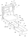
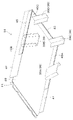
図8、図9に示すように、バッテリ支持部24は、バッテリ18が載置される載置プレート38と、載置プレート38から下方に突出する取付ブラケット39とを有している。図3に示すように、載置プレート38は、板面が上下方向を向き且つ電動モータ4及び車体フレーム8の上方に配置され、後部がサポートプレート35上に重ね合わされて載置されている。したがって、載置プレート38の後部(バッテリ支持部24の後部)がサポート部28に支持されている。載置プレート38の後端側は、サポートプレート35にボルト等によって取り付けられている。
図8、図9に示すように、バッテリ支持部24は、バッテリ18が載置される載置プレート38と、載置プレート38から下方に突出する取付ブラケット39とを有している。図3に示すように、載置プレート38は、板面が上下方向を向き且つ電動モータ4及び車体フレーム8の上方に配置され、後部がサポートプレート35上に重ね合わされて載置されている。したがって、載置プレート38の後部(バッテリ支持部24の後部)がサポート部28に支持されている。載置プレート38の後端側は、サポートプレート35にボルト等によって取り付けられている。
図8、図9に示すように、載置プレート38の車幅方向一側には前後方向に延びる第1側板41が固定され、載置プレート38の車幅方向他側には前後方向に延びる第2側板42が固定され、載置プレート38の前部には車幅方向に延びる前板43が固定され、載置プレート38の後部には車幅方向に延びる後板44が固定されている。第1側板41、第2側板42及び前板43は、板面の上下方向の中途部が載置プレート38の端部に固定されていて載置プレート38から上下に突出している。後板44は、載置プレート38の上面に固定されている。載置プレート38に載置されたバッテリ18は、後板44によって後方移動が規制され、第1側板41、第2側板42及び前板43にボルト等によって着脱可能に取り付けられる。また、バッテリ18は、第2支柱部材30上部の規制板32の規制部32aにもボルト等によって固定される(図3参照)。
図8、図9に示すように、本実施形態では、取付ブラケット39は複数設けられていて、載置プレート38の下方側に配置されている。具体的には、複数の取付ブラケット39は、第1側板41の内側の前後方向中途部に配置された第1ブラケット39Aと、第2側板42の内側の前後方向中途部に配置された第2ブラケット39Bと、前板43の内側の左部に配置された第3ブラケット39Cと、前板43の内側の右部に配置された第4ブラケット39Dとを含む。本実施形態では、第1ブラケット39A及び第2ブラケット39Bは、溝形鋼によって形成され、第3ブラケット39C及び第4ブラケット39Dは、山形鋼によって形成されている。これに限定されることはない。
第1ブラケット39A~第4ブラケット39Dは、取付枠45を介して第1側板41、第2側板42及び前板43に取り付けられている。取付枠45は、第1側板41の内側にボルト等によって取り付けられる第1板材45Aと、第2側板42の内側にボルト等によって取り付けられる第2板材45Bと、前板43の内側にボルト等によって取り付けられる第3板材45Cとを有している。第1ブラケット39Aは第1板材45Aの後部に固定され、第2ブラケット39Bは第2板材45Bの後部に固定され、第3ブラケット39Cは第3板材45Cの左部に固定され、第4ブラケット39Dは第3板材45Cの右部に固定されている。
図3、図5に示すように、インバータ支持部25は、載置プレート38の前部の下方に配置され且つ車体フレーム8に固定されていて、載置プレート38の前部を支持する。
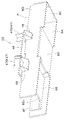
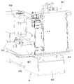
図10、図11に示すように、インバータ支持部25は、支持プレート46と、支持プレート46から上方に突出する支持ステー47とを有している。支持プレート46は、載置プレート38の下方に間隔をあけて配置される(図3参照)。また、支持プレート46は、板面が上下方向を向くように配置され、第1サイドプレート8Aの上端と第2サイドプレート8Bの上端とにわたって設けられている。支持プレート46の前部には、前方に開放状の切り欠き部46aが形成されている。支持プレート46の後部には、後方に開放状の切り欠き部46bが形成されている。支持プレート46の左部は第1サイドプレート8Aから左方に突出している。支持プレート46の右部は、第2サイドプレート8Bから右方に突出している。該支持プレート46の右部の突出部分の下面側の前部及び後部に取付具48が固定されている。支持プレート46の左部の突出部分の下面側にも同様の取付具48が固定されている。支持プレート46の左部の取付具48は第1サイドプレート8Aにボルト等によって取り付けられ、支持プレート46の右部の取付具48は第2サイドプレート8Bにボルト等によって取り付けられている。これによって、インバータ支持部25が車体フレーム8に取り付けられる。
図10、図11に示すように、インバータ支持部25は、支持プレート46と、支持プレート46から上方に突出する支持ステー47とを有している。支持プレート46は、載置プレート38の下方に間隔をあけて配置される(図3参照)。また、支持プレート46は、板面が上下方向を向くように配置され、第1サイドプレート8Aの上端と第2サイドプレート8Bの上端とにわたって設けられている。支持プレート46の前部には、前方に開放状の切り欠き部46aが形成されている。支持プレート46の後部には、後方に開放状の切り欠き部46bが形成されている。支持プレート46の左部は第1サイドプレート8Aから左方に突出している。支持プレート46の右部は、第2サイドプレート8Bから右方に突出している。該支持プレート46の右部の突出部分の下面側の前部及び後部に取付具48が固定されている。支持プレート46の左部の突出部分の下面側にも同様の取付具48が固定されている。支持プレート46の左部の取付具48は第1サイドプレート8Aにボルト等によって取り付けられ、支持プレート46の右部の取付具48は第2サイドプレート8Bにボルト等によって取り付けられている。これによって、インバータ支持部25が車体フレーム8に取り付けられる。
支持ステー47は、複数設けられている。複数の支持ステー47は、第1ステー47Aと、第2ステー47Bと、第3ステー47Cと、第4ステー47Dとを含む。本実施形態では、第1ステー47A及び第2ステー47Bは、溝形鋼によって形成され、第3ステー47C及び第4ステー47Dは、山形鋼によって形成されている。これに限定されることはない。第1ステー47Aは、支持プレート46の左部の後部であって取付具48に対応する位置に固定されている。第2ステー47Bは、支持プレート46の右部の後部であって取付具48に対応する位置に固定されている。第3ステー47Cは、支持プレート46の左部の前部であって取付具48に対応する位置に固定されている。第4ステー47Dは、支持プレート46の右部の前部であって取付具48に対応する位置に固定されている。
第1ステー47Aに第1ブラケット39Aが取り付けられ、第2ステー47Bに第2ブラケット39Bが取り付けられ、第3ステー47Cに第3ブラケット39Cが取り付けられ、第4ステー47Dに第4ブラケット39Dが取り付けられる(図3、図4、図5参照)。これにより、載置プレート38と支持プレート46との間にインバータ19が配置可能な空間が形成されるように、インバータ支持部25にバッテリ支持部24が取り付けられる。
インバータ本体19Aは、支持プレート46に載置されると共に該支持プレート46に前後方向位置調節可能に取り付けられる。インバータ側コネクタ19Bは、インバータ19の前部の下面側に設けられ、インバータ本体19Aから下方に突出すると共に、切り欠き部46aを介して支持プレート46(インバータ支持部25)から下方に突出している。
図3、図12に示すように、モータ側コネクタ4Aとインバータ側コネクタ19Bとは、第1サイドプレート8Aと第2サイドプレート8Bとの間に配置されている。この構成によれば、第1サイドプレート8Aと前記第2サイドプレート8Bとによって、モータ側コネクタ4Aとインバータ側コネクタ19Bと配線21とを保護することができる。また、モータ側コネクタ4A、インバータ側コネクタ19B及び配線21が傷つくのを防止することができると共に信頼性の向上を図ることができる。
図12に示すように、モータ側コネクタ4Aの配線接続口は前方を向いており、インバータ側コネクタ19Bの配線接続口は後方を向いている。つまり、モータ側コネクタ4Aとインバータ側コネクタ19Bとは前後方向で向き合っている。また、モータ側コネクタ4Aとインバータ側コネクタ19Bとは前後方向でオーバーラップするように配置されている。したがって、モータ側コネクタ4Aとインバータ側コネクタ19Bとを短い経路で接続することができ、配線21の発熱を抑えることができると共にシステムの効率向上につながる。また、配線21を短くすることにより、コスト低減も図れる。また、配線21が短く、屈曲を極力なくすことができるので、外的要因で配線21が傷つく可能性を減らすことができ、信頼性の向上を図ることができる。
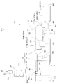
図12に示すように、車体フレーム8の前連結プレート8D,8Eにウォータポンプ94が取り付けられている。ウォータポンプ94は、電動モータ4、インバータ19及び後述する電圧コンバータ等を冷却する冷却水を循環させるポンプである。
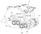
図3、図4に示すように、電動モータ4の側方には、該電動モータ4で駆動される油圧ポンプP1が配置されている。油圧ポンプP1は、例えば、伝動ケース9内のオイルを吸い込んで該オイルを作動油として各油圧駆動部に供給する。図13に示すように、電動モータ4及び油圧ポンプP1の後面側に動力伝達機構49が設けられ、この動力伝達機構49によって電動モータ4から油圧ポンプP1に動力が伝達される。図4に示すように、動力伝達機構49は、カバーケース61によって覆われている。カバーケース61は、前方開放状に形成されている。
図3、図4に示すように、電動モータ4の側方には、該電動モータ4で駆動される油圧ポンプP1が配置されている。油圧ポンプP1は、例えば、伝動ケース9内のオイルを吸い込んで該オイルを作動油として各油圧駆動部に供給する。図13に示すように、電動モータ4及び油圧ポンプP1の後面側に動力伝達機構49が設けられ、この動力伝達機構49によって電動モータ4から油圧ポンプP1に動力が伝達される。図4に示すように、動力伝達機構49は、カバーケース61によって覆われている。カバーケース61は、前方開放状に形成されている。
図13に示すように、動力伝達機構49は、ギヤ伝動機構によって構成されている。動力伝達機構49は、電動モータ4の出力軸に連結されて回転する出力ギヤ51と、油圧ポンプP1の入力軸に連結された入力ギヤ52と、出力ギヤ51と入力ギヤ52との間に配置されて出力ギヤ51から入力ギヤ52へ動力を伝達する1または複数の伝動ギヤ53とを有している。出力ギヤ51と入力ギヤ52と伝動ギヤ53は、平歯車によって形成され、前後方向に延伸する軸心回りに回転する。これに限定されることはない。本実施形態では、伝動ギヤ53は、複数設けられ、複数の伝動ギヤ53は、出力ギヤ51に噛み合う第1ギヤ53Aと、第1ギヤ53Aに噛み合う第2ギヤ53Bと、第2ギヤ53B及び入力ギヤ52に噛み合う第3ギヤ53Cとの3つのギヤを有して構成される。
図14、図15に示すように、バッテリ支持部24の前方であって、車体フレーム8の前部には、ラジエータR1、電圧コンバータ(DCDCコンバータ)C1、補機用バッテリBT、リザーブタンクR2、冷却ファン装置F1、オイルクーラO1等が取り付けられて支持されている。
図14に示すように、ラジエータR1、電圧コンバータC1、補機用バッテリBTは、左から順に車幅方向で並べて配置されている。リザーブタンクR2は、補機用バッテリBTの上方に配置されている。図15に示すように、冷却ファン装置F1は、ラジエータR1の後方に配置され、オイルクーラO1は、冷却ファン装置F1の後方に配置されている。
図14に示すように、ラジエータR1、電圧コンバータC1、補機用バッテリBTは、左から順に車幅方向で並べて配置されている。リザーブタンクR2は、補機用バッテリBTの上方に配置されている。図15に示すように、冷却ファン装置F1は、ラジエータR1の後方に配置され、オイルクーラO1は、冷却ファン装置F1の後方に配置されている。
ラジエータR1は、ウォータポンプ94で循環される冷却水を冷却ファン装置F1によって発生する冷却風によって冷却する放熱器である。電圧コンバータC1は、バッテリ18から送られてくる電力を降圧して補機用バッテリBTへ供給する装置である。補機用バッテリBTは、冷却ファン装置F1、インバータ19や電動モータ4等の電気機器を制御する制御装置、ランプ等の各種電気機器に電力を供給する蓄電池である。リザーブタンクR2は、高温時にラジエータR1から逃げる冷却水を貯留するタンクである。オイルクーラO1は、油圧機器等を作動させる作動油を冷却ファン装置F1によって発生する冷却風によって冷却する放熱器である。
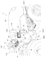
図16~図19に示すように、運転部10の前部操縦部11Aにバッテリ18の充電を行うための充電用コネクタ90が設けられている。図17に示すように、前部操縦部11Aは、ステアリングハンドル12を含むステアリング操作装置91と、ステアリング操作装置91の下部側を覆うフロントカバー(カバー体)92とを有している。フロントカバー(前部操縦部11A)92は、車体2上方に配置され、車体に搭載されている。つまり、フロントカバー92は、車体2に立設されている。また、フロントカバー92は、フロア16より上方に突出するように設けられている。ステアリングハンドル12は、フロントカバー92の背面上部に配置されている。フロントカバー92の上部には、モニタや、各種メータや、各種スイッチ等を有するインストルメントパネル54が設けられている。インストルメントパネル54には、バッテリ18の充電量を表示するバッテリ残量計が設けられる。フロントカバー92は、ボンネット20の後方に該ボンネット20に近接して配置され、前方に開放状に形成されている。また、ボンネット20の後端は後方に開放状である。したがって、フロントカバー92とボンネット20とは連通している。また、支持フレーム22のリヤフレーム部23(メインフレーム26)は、ボンネット20の後端側に配置されていて、リヤフレーム部23に設けられた取付プレート33は、フロントカバー92内に挿入状とされている。
図17に示すように、ステアリング操作装置91は、ステアリングハンドル12及びステアリングシャフト56を含むステアリング操作部材(操作部材)86と、ステアリングシャフト56を支持するステアリングポスト57と、ステアリングシャフト56にユニバーサルジョイント62を介して接続されたステアリングバルブ58と、ステアリングポスト57及びステアリングバルブ58等を支持するフレーム部材59とを含む。したがって、フロントカバー92は、ステアリング操作部材86の下部側を覆う。フレーム部材59は、リヤフレーム部23等の車体2側に取り付けられた部材に取り付けられて支持される。
上記ステアリング操作装置91にあっては、ステアリングハンドル12を回転操作すると、ステアリングシャフト56及びユニバーサルジョイント62を介してステアリングバルブ58が操作され、該ステアリングバルブ58が油圧ポンプP1から供給される作動油を前輪3Aを操舵するステアリングシリンダ(図示省略)に供給する。
図16~図19に示すように、充電用コネクタ90は、フロントカバー92(カバー体)の外面側に配置され、且つフロントカバー92(前部操縦部11A)の外方に露出して設けられている。また、充電用コネクタ90は、フロントカバー92の側面側(右側面側)に車幅方向外方(右方)を向くように配置されている。さらに、充電用コネクタ90は、図17に示すように、ステアリングハンドル12よりも前方且つ下方に配置されている。さらにまた、充電用コネクタ90は、図1に示すように、フロントカバー92の外側面上部であって、運転席6の座部6Aと略同じ高さ位置に配置されている。フロントカバー92の右側方は、開放状とされていて、充電する際に充電用コネクタ90の下方のフロア16に足を掛けることができる。フロントカバー92とフェンダ7との間は、通行可能なスペースが形成されている。
図16~図19に示すように、充電用コネクタ90は、フロントカバー92(カバー体)の外面側に配置され、且つフロントカバー92(前部操縦部11A)の外方に露出して設けられている。また、充電用コネクタ90は、フロントカバー92の側面側(右側面側)に車幅方向外方(右方)を向くように配置されている。さらに、充電用コネクタ90は、図17に示すように、ステアリングハンドル12よりも前方且つ下方に配置されている。さらにまた、充電用コネクタ90は、図1に示すように、フロントカバー92の外側面上部であって、運転席6の座部6Aと略同じ高さ位置に配置されている。フロントカバー92の右側方は、開放状とされていて、充電する際に充電用コネクタ90の下方のフロア16に足を掛けることができる。フロントカバー92とフェンダ7との間は、通行可能なスペースが形成されている。
図18に示すように、充電用コネクタ90は、接続端子部96aを有するコネクタ本体96と、該コネクタ本体96の接続端子部96a側を開閉可能に塞ぐキャップ97と、配線端子部96bとを有している。
接続端子部96aは、例えば、充電スタンドや充電ステーションと称される充電施設、或いは家屋に設置された充電設備などの外部電源設備に装備された給電用コネクタ64が接続される部位である。
接続端子部96aは、例えば、充電スタンドや充電ステーションと称される充電施設、或いは家屋に設置された充電設備などの外部電源設備に装備された給電用コネクタ64が接続される部位である。
コネクタ本体96は、ステアリングハンドル12よりも車幅方向外方(右方)で且つ運転席6よりも車幅方向外方に配置されている。
キャップ97は、図17に示すように、前部に設けられた枢支部97aが縦軸(上下方向に延伸する軸心)回りに回動するようにコネクタ本体96に取り付けられている。キャップ97の後方には、該キャップ97に係脱自在に係合して該キャップ97の開き動作を規制する係止具98が設けられている。係止具98は、コネクタ本体96に枢支されていて、縦軸回りに回動させることでキャップ97の開き動作の規制を解除することができる。キャップ97を縦軸回りに前方側に開き動作することで、コネクタ本体96の接続端子部96aを車幅方向外方側に露出させることができる。
キャップ97は、図17に示すように、前部に設けられた枢支部97aが縦軸(上下方向に延伸する軸心)回りに回動するようにコネクタ本体96に取り付けられている。キャップ97の後方には、該キャップ97に係脱自在に係合して該キャップ97の開き動作を規制する係止具98が設けられている。係止具98は、コネクタ本体96に枢支されていて、縦軸回りに回動させることでキャップ97の開き動作の規制を解除することができる。キャップ97を縦軸回りに前方側に開き動作することで、コネクタ本体96の接続端子部96aを車幅方向外方側に露出させることができる。
配線端子部96bは、図18に示すように、コネクタ本体96の背面に突出してフロントカバー92内に挿入される。配線端子部96bは、充電用コネクタ90とバッテリ18とを接続する接続配線が接続される部分である。外部電源側の給電用コネクタ64を接続端子部96aに接続すると、配線端子部96bから接続配線を介してバッテリ18に電気が充電される。
図16、図17に示すように、充電用コネクタ90の前方側には、表示ランプ101と、サイドミラー100とが配置されている。表示ランプ101は、例えば、複数のランプを組み合わせて構成されたコンビネーションランプである。コンビネーションランプを構成するランプは、ポジションランプ、ウインカーランプ、ハザードランプ等である。サイドミラー100は、車体2の後方側を視認するミラーである。表示ランプ101及びサイドミラー100のミラー本体100aは、充電用コネクタ90の前方で、且つ充電用コネクタ90よりも車幅方向外方に位置している。
図19に示すように、充電用コネクタ90は、コネクタブラケット93に取り付けられている。図20に示すように、コネクタブラケット93は、第1ブラケット部材66と、第2ブラケット部材67とを有している。第1ブラケット部材66は、リヤフレーム部23に設けられた取付プレート(取付部)33の縦板部33aに重ね合わされて取り付けられる取付壁部66aと、取付壁部66aの前端から車幅方向外方に延びる延出壁部66bと、延出壁部66bの延出端(車幅方向外方側の端部)から後方に延びるランプ取付部66cと、取付壁部66aとランプ取付部66cとを連結するパイプ材等からなる補強部材69とを有している。延出壁部66bは、フロントカバー92の内部側から車幅方向外方に突出しており、延出壁部66bの該突出した部分に取付穴68が形成されている。
第2ブラケット部材67は、第1ブラケット部材66に取り付けられる第1部材71と、第1部材71に固定された第2部材72とを有している。第1部材71は、板面が車幅方向を向くように形成された第1壁部71aと、第1壁部71aの前端下部から車幅方向外方に延出されていて延出壁部66bの取付穴68が形成された部分に取り付けられる第2壁部71bとを有している。第2部材72は、第1部材71の第1壁部71aから後方に突出するように固定されている。本実施形態では、第2部材72は、後方に向かうにつれて車幅方向内方(左方)に移行する傾斜方向に延びている。第2部材72に充電用コネクタ90が車幅方向外方側から取り付けられる。つまり、第2部材72は、充電用コネクタ90が取り付けられるコネクタ取付部である。
以上のように、コネクタブラケット93は、フロントカバー92の外部で充電用コネクタ90が取り付けられるコネクタ取付部(第2部材72)と、フロントカバー92の内部側に設けられた取付部(取付プレート33)に取り付けられる取付壁部66aとを有している。
図20に示すように、第2ブラケット部材67の第1部材71の上部にサイドミラー100の支柱部材73が取付具74を介して取り付けられる。したがって、第1部材71の上部がサイドミラー100が取り付けられるミラー取付部75とされている。また、第1ブラケット部材66のランプ取付部66cには、表示ランプ101のランプステー76が取り付けられる。
図20に示すように、第2ブラケット部材67の第1部材71の上部にサイドミラー100の支柱部材73が取付具74を介して取り付けられる。したがって、第1部材71の上部がサイドミラー100が取り付けられるミラー取付部75とされている。また、第1ブラケット部材66のランプ取付部66cには、表示ランプ101のランプステー76が取り付けられる。
以上のように、コネクタブラケット93は、サイドミラー100が取り付けられるミラー取付部75と、表示ランプ101が取り付けられるランプ取付部66cとを有している。
充電用コネクタ90は、側部操縦部11Bのカバー体14の外面側に配置することもできる。つまり、充電用コネクタ90は、運転席6の周囲に設けられたカバー体であって、操作部材の下部側を覆うカバー体に設けられる。
充電用コネクタ90は、側部操縦部11Bのカバー体14の外面側に配置することもできる。つまり、充電用コネクタ90は、運転席6の周囲に設けられたカバー体であって、操作部材の下部側を覆うカバー体に設けられる。
上記の電動トラクタ1にあっては、走行装置3を駆動する電動モータ4と、バッテリ18と、バッテリ18からの電力を電動モータ4へ供給するインバータ19と、運転席6の前方に配置されてバッテリ18を覆うボンネット20の下方に配置された車体フレーム8と、車体フレーム8に取り付けられた支持フレーム22と、を備え、支持フレーム22は、電動モータ4の上方且つ車体フレーム8の上方に配置されたバッテリ18を支持するバッテリ支持部24と、バッテリ支持部24と車体フレーム8との間で且つ電動モータ4の前方に配置されたインバータ19を支持するインバータ支持部25とを有している。
この構成によれば、電動モータ4の上方且つ車体フレーム8の上方に配置されたバッテリ18を支持するバッテリ支持部24と、バッテリ支持部24と車体フレーム8との間で且つ電動モータ4の前方に配置されたインバータ19を支持するインバータ支持部25とを設けることで、電動モータ4とインバータ19とを近い位置に配置でき、電動モータ4とインバータ19とを短い経路で繋ぐことができる。
また、バッテリ支持部24は、バッテリ18が載置される載置プレート38と、載置プレート38から下方に突出する取付ブラケット39とを有し、インバータ支持部25は、インバータ19が載置される支持プレート46であって載置プレート38の下方に間隔をあけて配置され且つ車体フレーム8に取り付けられる支持プレート46と、支持プレート46から上方に突出すると共に取付ブラケット39が取り付けられる支持ステー47とを有している。
この構成によれば、バッテリ18の下方で且つ電動モータ4の前方にインバータ19を配置するスペースを形成することができる。
また、インバータ支持部25は、インバータ19が電動モータ4と前後方向でオーバーラップして配置されるようにインバータ19を支持する。
この構成によれば、電動モータ4及びインバータ19をコンパクトに配置することができる。
また、インバータ支持部25は、インバータ19が電動モータ4と前後方向でオーバーラップして配置されるようにインバータ19を支持する。
この構成によれば、電動モータ4及びインバータ19をコンパクトに配置することができる。
また、支持フレーム22は、載置プレート38の後部下方に配置されたサポート部28であって車体フレーム8に固定されて載置プレート38の後部を支持するサポート部28を有し、インバータ支持部25は、載置プレート38の前部を支持する。
この構成によれば、サポート部28及びインバータ支持部25でバッテリ18を十分に支持することができる。
この構成によれば、サポート部28及びインバータ支持部25でバッテリ18を十分に支持することができる。
また、サポート部28は、載置プレート38の後部が載置されるサポートプレート35であって電動モータ4の上方に配置されたサポートプレート35と、サポートプレート35の下面側に設けられていて車体フレーム8に固定された支持脚36とを有している。
電動モータ4の上方にサポートプレート35を配置することで、サポート部28及び電動モータ4をコンパクトに配置することができる。
電動モータ4の上方にサポートプレート35を配置することで、サポート部28及び電動モータ4をコンパクトに配置することができる。
また、電動モータ4は、当該電動モータ4の前部側に設けられたモータ側コネクタ4Aを有し、インバータ19は、モータ側コネクタ4Aに接続されるインバータ側コネクタ19Bであってモータ側コネクタ4Aの前方に配置されたインバータ側コネクタ19Bを有している。
この構成によれば、モータ側コネクタ4Aとインバータ側コネクタ19Bとを短い経路で接続することができる。
この構成によれば、モータ側コネクタ4Aとインバータ側コネクタ19Bとを短い経路で接続することができる。
また、モータ側コネクタ4Aは、電動モータ4の前下部に設けられ、インバータ19は、インバータ支持部25に載置されて支持されるインバータ本体19Aが電動モータ4の上部の後方に前後方向でオーバーラップするように配置され、インバータ側コネクタ19Bは、インバータ本体19Aの下部側に設けられていてインバータ支持部25から下方に突出している。
この構成によっても、モータ側コネクタ4Aとインバータ側コネクタ19Bとをさらに短い経路で接続することができる。
また、インバータ支持部25は、インバータ側コネクタ19Bをインバータ支持部25から下方に突出させる切り欠き部46aを有している。
この構成によれば、インバータ19をインバータ支持部25で良好に支持しながらインバータ側コネクタ19Bをインバータ支持部25から下方に突出させることができる。
また、インバータ支持部25は、インバータ側コネクタ19Bをインバータ支持部25から下方に突出させる切り欠き部46aを有している。
この構成によれば、インバータ19をインバータ支持部25で良好に支持しながらインバータ側コネクタ19Bをインバータ支持部25から下方に突出させることができる。
また、車体フレーム8は、車幅方向で間隔をあけて並べて配置された第1サイドプレート8A及び第2サイドプレート8Bを有し、モータ側コネクタ4A及びインバータ側コネクタ19Bは、第1サイドプレート8Aと第2サイドプレート8Bとの間に配置されている。
この構成によれば、モータ側コネクタ4A及びインバータ側コネクタ19Bを保護することができる。
この構成によれば、モータ側コネクタ4A及びインバータ側コネクタ19Bを保護することができる。
また、電動トラクタ1は、運転席6及び運転席6の周囲に設けられた操縦部(前部操縦部11A)を含む運転部10と、運転部10が搭載された車体2と、車体2を走行可能に支持する走行装置3と、走行装置3を駆動する電動モータ4と、電動モータ4に電力を供給するバッテリ18と、バッテリ18の充電を行うための充電用コネクタ90と、を備え、操縦部11Aは、操作部材(ステアリング操作部材86)と、操作部材86の下部側を覆うカバー体(フロントカバー92)とを含み、充電用コネクタ90は、カバー体92の外面側に操縦部の外方に露出して配置されている。
この構成によれば、バッテリ18の充電を容易に行うことができる。
また、充電用コネクタ90は、カバー体92の側面側に車幅方向外方を向くように配置されている。
この構成によれば、さらに、バッテリ18の充電を容易に行うことができる。
また、操縦部11Aは、運転席6の前方に配置された操作部材としてのステアリング操作部材86と、ステアリング操作部材86の下部側を覆うカバー体としてのフロントカバー92とを含み、充電用コネクタ90は、フロントカバー92の外側面の上部に配置されている。
また、充電用コネクタ90は、カバー体92の側面側に車幅方向外方を向くように配置されている。
この構成によれば、さらに、バッテリ18の充電を容易に行うことができる。
また、操縦部11Aは、運転席6の前方に配置された操作部材としてのステアリング操作部材86と、ステアリング操作部材86の下部側を覆うカバー体としてのフロントカバー92とを含み、充電用コネクタ90は、フロントカバー92の外側面の上部に配置されている。
この構成によれば、外部電源側の給電用コネクタを接続しやすい位置に充電用コネクタ90を配置することができる。
また、ステアリング操作部材86は、ステアリングハンドル12を含み、充電用コネクタ90は、ステアリングハンドル12よりも前方に配置されている。
この構成によれば、充電用コネクタ90に外部電源側のコネクタを接続する際にステアリングハンドル12が邪魔になるのを抑制することができる。
また、ステアリング操作部材86は、ステアリングハンドル12を含み、充電用コネクタ90は、ステアリングハンドル12よりも前方に配置されている。
この構成によれば、充電用コネクタ90に外部電源側のコネクタを接続する際にステアリングハンドル12が邪魔になるのを抑制することができる。
また、充電用コネクタ90は、フロントカバー92の外側面における運転席6の座部6Aと略同じ高さ位置に配置されている。
この構成によっても、外部電源側の給電用コネクタを接続しやすい位置に充電用コネクタ90を配置することができる。
また、充電用コネクタ90が取り付けられるコネクタブラケット93を備え、コネクタブラケット93は、フロントカバー92の外部で充電用コネクタ90が取り付けられるコネクタ取付部(第2部材72)と、フロントカバー92の内部側に設けられた取付部(取付プレート33)に取り付けられる取付壁部66aとを有している。
この構成によっても、外部電源側の給電用コネクタを接続しやすい位置に充電用コネクタ90を配置することができる。
また、充電用コネクタ90が取り付けられるコネクタブラケット93を備え、コネクタブラケット93は、フロントカバー92の外部で充電用コネクタ90が取り付けられるコネクタ取付部(第2部材72)と、フロントカバー92の内部側に設けられた取付部(取付プレート33)に取り付けられる取付壁部66aとを有している。
この構成によれば、コネクタブラケット93を十分に支持することができると共に充電用コネクタ90の取付を容易に行うことができる。
また、コネクタブラケット93は、サイドミラー100が取り付けられるミラー取付部75を有している。
この構成によれば、部材の兼用化によるコスト低減を図ることができる。
また、コネクタブラケット93は、サイドミラー100が取り付けられるミラー取付部75を有している。
この構成によれば、部材の兼用化によるコスト低減を図ることができる。
また、コネクタブラケット93は、表示ランプ101が取り付けられるランプ取付部66cを有している。
この構成によっても、部材の兼用化によるコスト低減を図ることができる。
以上、本発明の一実施形態について説明したが、今回開示された実施の形態はすべての点で例示であって制限的なものではないと考えられるべきである。本発明の範囲は上記した説明ではなくて請求の範囲によって示され、請求の範囲と均等の意味及び範囲内でのすべての変更が含まれることが意図される。
この構成によっても、部材の兼用化によるコスト低減を図ることができる。
以上、本発明の一実施形態について説明したが、今回開示された実施の形態はすべての点で例示であって制限的なものではないと考えられるべきである。本発明の範囲は上記した説明ではなくて請求の範囲によって示され、請求の範囲と均等の意味及び範囲内でのすべての変更が含まれることが意図される。
2 車体
3 走行装置
4 電動モータ
4A モータ側コネクタ
6 運転席
6A 座部
8 車体フレーム
8A 第1サイドプレート
8B 第2サイドプレート
10 運転部
11A 操縦部(前部操縦部)
12 ステアリングハンドル
18 バッテリ
19 インバータ
19A インバータ本体
19B インバータ側コネクタ
20 ボンネット
22 支持フレーム
24 バッテリ支持部
25 インバータ支持部
28 サポート部
33 取付部(取付プレート)
35 サポートプレート
36 支持脚
38 載置プレート
39 取付ブラケット
46 支持プレート
46a 切り欠き部
47 支持ステー
66a 取付壁部
66c ランプ取付部
72 コネクタ取付部(第2部材)
75 ミラー取付部
86 操作部材(ステアリング操作部材)
90 充電用コネクタ
92 カバー体(フロントカバー)
93 コネクタブラケット
100 サイドミラー
101 表示ランプ
3 走行装置
4 電動モータ
4A モータ側コネクタ
6 運転席
6A 座部
8 車体フレーム
8A 第1サイドプレート
8B 第2サイドプレート
10 運転部
11A 操縦部(前部操縦部)
12 ステアリングハンドル
18 バッテリ
19 インバータ
19A インバータ本体
19B インバータ側コネクタ
20 ボンネット
22 支持フレーム
24 バッテリ支持部
25 インバータ支持部
28 サポート部
33 取付部(取付プレート)
35 サポートプレート
36 支持脚
38 載置プレート
39 取付ブラケット
46 支持プレート
46a 切り欠き部
47 支持ステー
66a 取付壁部
66c ランプ取付部
72 コネクタ取付部(第2部材)
75 ミラー取付部
86 操作部材(ステアリング操作部材)
90 充電用コネクタ
92 カバー体(フロントカバー)
93 コネクタブラケット
100 サイドミラー
101 表示ランプ
Claims (17)
- 走行装置を駆動する電動モータと、
バッテリと、
前記バッテリからの電力を前記電動モータへ供給するインバータと、
運転席の前方に配置されて前記バッテリを覆うボンネットの下方に配置された車体フレームと、
前記車体フレームに取り付けられた支持フレームと、
を備え、
前記支持フレームは、
前記電動モータの上方且つ前記車体フレームの上方に配置された前記バッテリを支持するバッテリ支持部と、
前記バッテリ支持部と前記車体フレームとの間で且つ前記電動モータの前方に配置された前記インバータを支持するインバータ支持部とを有している電動トラクタ。 - 前記バッテリ支持部は、前記バッテリが載置される載置プレートと、前記載置プレートから下方に突出する取付ブラケットとを有し、
前記インバータ支持部は、前記インバータが載置される支持プレートであって前記載置プレートの下方に間隔をあけて配置され且つ前記車体フレームに取り付けられる支持プレートと、前記支持プレートから上方に突出すると共に前記取付ブラケットが取り付けられる支持ステーとを有している請求項1に記載の電動トラクタ。 - 前記インバータ支持部は、前記インバータが前記電動モータと前後方向でオーバーラップして配置されるように前記インバータを支持する請求項1又は2に記載の電動トラクタ。
- 前記支持フレームは、前記載置プレートの後部下方に配置されたサポート部であって前記車体フレームに固定されて前記載置プレートの後部を支持するサポート部を有し、
前記インバータ支持部は、前記載置プレートの前部を支持する請求項2又は3に記載の電動トラクタ。 - 前記サポート部は、前記載置プレートの後部が載置されるサポートプレートであって前記電動モータの上方に配置されたサポートプレートと、前記サポートプレートの下面側に設けられていて前記車体フレームに固定された支持脚とを有している請求項4に記載の電動トラクタ。
- 前記電動モータは、当該電動モータの前部側に設けられたモータ側コネクタを有し、
前記インバータは、前記モータ側コネクタに接続されるインバータ側コネクタであって前記モータ側コネクタの前方に配置されたインバータ側コネクタを有している請求項1~5のいずれか1項に記載の電動トラクタ。 - 前記モータ側コネクタは、前記電動モータの前下部に設けられ、
前記インバータは、前記インバータ支持部に載置されて支持されるインバータ本体が前記電動モータの上部の後方に前後方向でオーバーラップするように配置され、
前記インバータ側コネクタは、前記インバータ本体の下部側に設けられていて前記インバータ支持部から下方に突出している請求項6に記載の電動トラクタ。 - 前記インバータ支持部は、前記インバータ側コネクタを前記インバータ支持部から下方に突出させる切り欠き部を有している請求項7に記載の電動トラクタ。
- 前記車体フレームは、車幅方向で間隔をあけて並べて配置された第1サイドプレート及び第2サイドプレートを有し、
前記モータ側コネクタ及び前記インバータ側コネクタは、前記第1サイドプレートと前記第2サイドプレートとの間に配置されている請求項6~8のいずれか1項に記載の電動トラクタ。 - 運転席及び前記運転席の周囲に設けられた操縦部を含む運転部と、
前記運転部が搭載された車体と、
前記車体を走行可能に支持する走行装置と、
前記走行装置を駆動する電動モータと、
前記電動モータに電力を供給するバッテリと、
前記バッテリの充電を行うための充電用コネクタと、
を備え、
前記操縦部は、操作部材と、前記操作部材の下部側を覆うカバー体とを含み、
前記充電用コネクタは、前記カバー体の外面側に前記操縦部の外方に露出して配置されている電動トラクタ。 - 前記充電用コネクタは、前記カバー体の側面側に車幅方向外方を向くように配置されている請求項10に記載の電動トラクタ。
- 前記操縦部は、前記運転席の前方に配置された前記操作部材としてのステアリング操作部材と、前記ステアリング操作部材の下部側を覆う前記カバー体としてのフロントカバーとを含み、
前記充電用コネクタは、前記フロントカバーの外側面の上部に配置されている請求項10又は11に記載の電動トラクタ。 - 前記ステアリング操作部材は、ステアリングハンドルを含み、
前記充電用コネクタは、前記ステアリングハンドルよりも前方に配置されている請求項12に記載の電動トラクタ。 - 前記充電用コネクタは、前記フロントカバーの外側面における前記運転席の座部と略同じ高さ位置に配置されている請求項12又は13に記載の電動トラクタ。
- 前記充電用コネクタが取り付けられるコネクタブラケットを備え、
前記コネクタブラケットは、前記フロントカバーの外部で充電用コネクタが取り付けられるコネクタ取付部と、前記フロントカバーの内部側に設けられた取付部に取り付けられる取付壁部とを有している請求項10~14のいずれか1項に記載の電動トラクタ。 - 前記コネクタブラケットは、サイドミラーが取り付けられるミラー取付部を有している請求項15に記載の電動トラクタ。
- 前記コネクタブラケットは、表示ランプが取り付けられるランプ取付部を有している請求項15又は16に記載の電動トラクタ。
Priority Applications (2)
| Application Number | Priority Date | Filing Date | Title |
|---|---|---|---|
| EP21877505.4A EP4227192A4 (en) | 2020-10-05 | 2021-10-01 | ELECTRIC TRACTOR |
| US18/126,636 US20230227106A1 (en) | 2020-10-05 | 2023-03-27 | Electric tractor |
Applications Claiming Priority (4)
| Application Number | Priority Date | Filing Date | Title |
|---|---|---|---|
| JP2020-168259 | 2020-10-05 | ||
| JP2020168258A JP7458956B2 (ja) | 2020-10-05 | 2020-10-05 | 電動トラクタ |
| JP2020-168258 | 2020-10-05 | ||
| JP2020168259A JP7524020B2 (ja) | 2020-10-05 | 2020-10-05 | 電動トラクタ |
Related Child Applications (1)
| Application Number | Title | Priority Date | Filing Date |
|---|---|---|---|
| US18/126,636 Continuation US20230227106A1 (en) | 2020-10-05 | 2023-03-27 | Electric tractor |
Publications (1)
| Publication Number | Publication Date |
|---|---|
| WO2022075206A1 true WO2022075206A1 (ja) | 2022-04-14 |
Family
ID=81126899
Family Applications (1)
| Application Number | Title | Priority Date | Filing Date |
|---|---|---|---|
| PCT/JP2021/036369 Ceased WO2022075206A1 (ja) | 2020-10-05 | 2021-10-01 | 電動トラクタ |
Country Status (3)
| Country | Link |
|---|---|
| US (1) | US20230227106A1 (ja) |
| EP (1) | EP4227192A4 (ja) |
| WO (1) | WO2022075206A1 (ja) |
Cited By (6)
| Publication number | Priority date | Publication date | Assignee | Title |
|---|---|---|---|---|
| CN115056866A (zh) * | 2022-06-30 | 2022-09-16 | 上海十联重工有限公司 | 一种安全稳定高效的电动牵引车 |
| EP4289648A1 (en) | 2022-06-06 | 2023-12-13 | Kanzaki Kokyukoki Mfg. Co., Ltd. | Electric work vehicle |
| EP4512645A1 (en) * | 2023-07-03 | 2025-02-26 | Kubota Corporation | Electric work vehicle |
| US20250140958A1 (en) * | 2023-10-30 | 2025-05-01 | Kubota Corporation | Component layout of air cooling components in electric work vehicle |
| US20250135861A1 (en) * | 2023-10-30 | 2025-05-01 | Kubota Corporation | Component layout of electric components in electric work vehicle |
| EP4609690A4 (en) * | 2023-01-17 | 2026-02-18 | Nanjing Chervon Ind Co Ltd | RIDE-ON LAWN MOWER |
Families Citing this family (7)
| Publication number | Priority date | Publication date | Assignee | Title |
|---|---|---|---|---|
| JP7323349B2 (ja) * | 2019-06-24 | 2023-08-08 | 株式会社クボタ | 電動作業車 |
| JP2025042488A (ja) * | 2023-09-14 | 2025-03-27 | ヤンマーホールディングス株式会社 | 電動式作業機械 |
| US12603343B2 (en) * | 2023-10-30 | 2026-04-14 | Kubota Corporation | Component layout of liquid cooling components in electric work vehicle |
| DE102023131380A1 (de) * | 2023-11-10 | 2025-05-15 | Tadus GmbH | Traktorteilstruktur für eine elektrisch angetriebene landwirtschaftliche Zugmaschinee |
| EP4678448A1 (de) | 2024-07-12 | 2026-01-14 | Deere & Company | Antriebsanordnung, achse und arbeitsmaschine |
| EP4678444A1 (de) | 2024-07-12 | 2026-01-14 | Deere & Company | Antriebsanordnung, achse und arbeitsmaschine |
| EP4678437A1 (de) | 2024-07-12 | 2026-01-14 | Deere & Company | Antriebsanordnung, achse und arbeitsmaschine |
Citations (3)
| Publication number | Priority date | Publication date | Assignee | Title |
|---|---|---|---|---|
| JP2013068177A (ja) | 2011-09-22 | 2013-04-18 | Kubota Corp | 作業車の作業動力取り出し構造 |
| KR20130040286A (ko) * | 2011-10-14 | 2013-04-24 | 대동공업주식회사 | 전기구동식 농용 작업차 구조 |
| JP6471626B2 (ja) | 2015-06-22 | 2019-02-20 | 井関農機株式会社 | トラクタ |
Family Cites Families (17)
| Publication number | Priority date | Publication date | Assignee | Title |
|---|---|---|---|---|
| JP2002167181A (ja) * | 2000-11-28 | 2002-06-11 | Nippon Yusoki Co Ltd | バッテリ保護構造 |
| US20110046831A1 (en) * | 2009-02-11 | 2011-02-24 | Ananthakrishna Anil | Electrically powered motorized vehicle with continuously variable transmission and combined hybrid system |
| BR112014015371A8 (pt) * | 2011-12-22 | 2017-06-13 | Yamaha Motor Co Ltd | veículo elétrico do tipo de montar |
| BR112014015034A2 (pt) * | 2011-12-22 | 2017-06-13 | Yamaha Motor Co Ltd | veículo elétrico tipo moto |
| CN205853881U (zh) * | 2015-06-25 | 2017-01-04 | 井关农机株式会社 | 车辆 |
| JP6290847B2 (ja) * | 2015-10-22 | 2018-03-07 | 本田技研工業株式会社 | 電動車両のコネクタ取付構造 |
| WO2021071655A1 (en) * | 2019-10-11 | 2021-04-15 | Ariens Company | Power source and control system for a lawn mower |
| CN214524218U (zh) * | 2020-11-10 | 2021-10-29 | 浙江春风动力股份有限公司 | 一种行驶平稳的电动摩托车 |
| JP2023015905A (ja) * | 2021-07-20 | 2023-02-01 | ヤマハ発動機株式会社 | 電動車両 |
| JP2023015904A (ja) * | 2021-07-20 | 2023-02-01 | ヤマハ発動機株式会社 | 鞍乗型電動車両 |
| WO2023039874A1 (en) * | 2021-09-18 | 2023-03-23 | Nanjing Chervon Industry Co., Ltd. | Riding lawn mower, display interface of a power tool and riding machine |
| US12024037B2 (en) * | 2021-11-03 | 2024-07-02 | Zero Motorcycles, Inc. | Charging system, vehicle including a charging system, and charging method |
| US12595028B2 (en) * | 2022-04-07 | 2026-04-07 | Taiga Motors Inc. | Protective cover for electric vehicle |
| JP7696866B2 (ja) * | 2022-06-23 | 2025-06-23 | 株式会社クボタ | 作業機 |
| US20250125442A1 (en) * | 2023-10-13 | 2025-04-17 | Kubota Corporation | Air cooling system for an electric vehicle |
| US12603343B2 (en) * | 2023-10-30 | 2026-04-14 | Kubota Corporation | Component layout of liquid cooling components in electric work vehicle |
| US20250135923A1 (en) * | 2023-10-30 | 2025-05-01 | Kubota Corporation | Electric work vehicle including plurality of external charge ports |
-
2021
- 2021-10-01 WO PCT/JP2021/036369 patent/WO2022075206A1/ja not_active Ceased
- 2021-10-01 EP EP21877505.4A patent/EP4227192A4/en active Pending
-
2023
- 2023-03-27 US US18/126,636 patent/US20230227106A1/en active Pending
Patent Citations (3)
| Publication number | Priority date | Publication date | Assignee | Title |
|---|---|---|---|---|
| JP2013068177A (ja) | 2011-09-22 | 2013-04-18 | Kubota Corp | 作業車の作業動力取り出し構造 |
| KR20130040286A (ko) * | 2011-10-14 | 2013-04-24 | 대동공업주식회사 | 전기구동식 농용 작업차 구조 |
| JP6471626B2 (ja) | 2015-06-22 | 2019-02-20 | 井関農機株式会社 | トラクタ |
Non-Patent Citations (1)
| Title |
|---|
| See also references of EP4227192A4 |
Cited By (6)
| Publication number | Priority date | Publication date | Assignee | Title |
|---|---|---|---|---|
| EP4289648A1 (en) | 2022-06-06 | 2023-12-13 | Kanzaki Kokyukoki Mfg. Co., Ltd. | Electric work vehicle |
| CN115056866A (zh) * | 2022-06-30 | 2022-09-16 | 上海十联重工有限公司 | 一种安全稳定高效的电动牵引车 |
| EP4609690A4 (en) * | 2023-01-17 | 2026-02-18 | Nanjing Chervon Ind Co Ltd | RIDE-ON LAWN MOWER |
| EP4512645A1 (en) * | 2023-07-03 | 2025-02-26 | Kubota Corporation | Electric work vehicle |
| US20250140958A1 (en) * | 2023-10-30 | 2025-05-01 | Kubota Corporation | Component layout of air cooling components in electric work vehicle |
| US20250135861A1 (en) * | 2023-10-30 | 2025-05-01 | Kubota Corporation | Component layout of electric components in electric work vehicle |
Also Published As
| Publication number | Publication date |
|---|---|
| EP4227192A4 (en) | 2025-04-02 |
| US20230227106A1 (en) | 2023-07-20 |
| EP4227192A1 (en) | 2023-08-16 |
Similar Documents
| Publication | Publication Date | Title |
|---|---|---|
| WO2022075206A1 (ja) | 電動トラクタ | |
| JP2022060665A (ja) | 電動トラクタ | |
| JP7631585B2 (ja) | 電動トラクタ | |
| JP5814577B2 (ja) | 電動式作業車両及びそのバッテリ保持構造 | |
| JP7304750B2 (ja) | 電動作業車 | |
| JP7149213B2 (ja) | 作業車両 | |
| CN113710523A (zh) | 电动作业车辆 | |
| JP5684768B2 (ja) | 作業車 | |
| CN116061669A (zh) | 电动拖拉机 | |
| WO2012128196A1 (ja) | 電動式作業車両及びそのベースフレーム | |
| JP2022101315A (ja) | 作業車 | |
| JP7675643B2 (ja) | 電動作業車 | |
| JP2017013688A (ja) | 車両 | |
| JP2024094128A (ja) | 電動作業車 | |
| JP7546543B2 (ja) | 電動作業車 | |
| WO2024143322A1 (ja) | 作業車両 | |
| JP7519983B2 (ja) | 電動作業車 | |
| JP2024047248A (ja) | 作業車 | |
| JP2023112412A (ja) | 電動作業車 | |
| JP7797372B2 (ja) | 作業車両 | |
| JP7378385B2 (ja) | 作業車 | |
| JP7519982B2 (ja) | 電動作業車 | |
| JP7555326B2 (ja) | 電動作業車 | |
| JP2024095104A (ja) | 作業車両 | |
| WO2024143323A1 (ja) | 作業車両 |
Legal Events
| Date | Code | Title | Description |
|---|---|---|---|
| 121 | Ep: the epo has been informed by wipo that ep was designated in this application |
Ref document number: 21877505 Country of ref document: EP Kind code of ref document: A1 |
|
| NENP | Non-entry into the national phase |
Ref country code: DE |
|
| ENP | Entry into the national phase |
Ref document number: 2021877505 Country of ref document: EP Effective date: 20230508 |