WO2022075380A1 - ドライバホルダ、ドライバモジュール及びヘッドセット - Google Patents
ドライバホルダ、ドライバモジュール及びヘッドセット Download PDFInfo
- Publication number
- WO2022075380A1 WO2022075380A1 PCT/JP2021/037052 JP2021037052W WO2022075380A1 WO 2022075380 A1 WO2022075380 A1 WO 2022075380A1 JP 2021037052 W JP2021037052 W JP 2021037052W WO 2022075380 A1 WO2022075380 A1 WO 2022075380A1
- Authority
- WO
- WIPO (PCT)
- Prior art keywords
- driver
- microphone
- holder
- sound path
- module case
- Prior art date
- Legal status (The legal status is an assumption and is not a legal conclusion. Google has not performed a legal analysis and makes no representation as to the accuracy of the status listed.)
- Ceased
Links
Images








Classifications
-
- H—ELECTRICITY
- H04—ELECTRIC COMMUNICATION TECHNIQUE
- H04R—LOUDSPEAKERS, MICROPHONES, GRAMOPHONE PICK-UPS OR LIKE ACOUSTIC ELECTROMECHANICAL TRANSDUCERS; ELECTRIC HEARING AIDS; PUBLIC ADDRESS SYSTEMS
- H04R1/00—Details of transducers, loudspeakers or microphones
- H04R1/10—Earpieces; Attachments therefor ; Earphones; Monophonic headphones
- H04R1/1058—Manufacture or assembly
- H04R1/1075—Mountings of transducers in earphones or headphones
-
- H—ELECTRICITY
- H04—ELECTRIC COMMUNICATION TECHNIQUE
- H04R—LOUDSPEAKERS, MICROPHONES, GRAMOPHONE PICK-UPS OR LIKE ACOUSTIC ELECTROMECHANICAL TRANSDUCERS; ELECTRIC HEARING AIDS; PUBLIC ADDRESS SYSTEMS
- H04R1/00—Details of transducers, loudspeakers or microphones
- H04R1/10—Earpieces; Attachments therefor ; Earphones; Monophonic headphones
- H04R1/1016—Earpieces of the intra-aural type
-
- H—ELECTRICITY
- H04—ELECTRIC COMMUNICATION TECHNIQUE
- H04R—LOUDSPEAKERS, MICROPHONES, GRAMOPHONE PICK-UPS OR LIKE ACOUSTIC ELECTROMECHANICAL TRANSDUCERS; ELECTRIC HEARING AIDS; PUBLIC ADDRESS SYSTEMS
- H04R1/00—Details of transducers, loudspeakers or microphones
- H04R1/10—Earpieces; Attachments therefor ; Earphones; Monophonic headphones
- H04R1/1058—Manufacture or assembly
-
- H—ELECTRICITY
- H04—ELECTRIC COMMUNICATION TECHNIQUE
- H04R—LOUDSPEAKERS, MICROPHONES, GRAMOPHONE PICK-UPS OR LIKE ACOUSTIC ELECTROMECHANICAL TRANSDUCERS; ELECTRIC HEARING AIDS; PUBLIC ADDRESS SYSTEMS
- H04R1/00—Details of transducers, loudspeakers or microphones
- H04R1/10—Earpieces; Attachments therefor ; Earphones; Monophonic headphones
- H04R1/1083—Reduction of ambient noise
-
- H—ELECTRICITY
- H04—ELECTRIC COMMUNICATION TECHNIQUE
- H04R—LOUDSPEAKERS, MICROPHONES, GRAMOPHONE PICK-UPS OR LIKE ACOUSTIC ELECTROMECHANICAL TRANSDUCERS; ELECTRIC HEARING AIDS; PUBLIC ADDRESS SYSTEMS
- H04R2460/00—Details of hearing devices, i.e. of ear- or headphones covered by H04R1/10 or H04R5/033 but not provided for in any of their subgroups, or of hearing aids covered by H04R25/00 but not provided for in any of its subgroups
- H04R2460/01—Hearing devices using active noise cancellation
Definitions
- This disclosure relates to driver holders, driver modules and headsets.
- Japanese Patent Application Laid-Open No. 2015-126509 provides a partition portion inside the ear tip corresponding to the external auditory canal insertion portion, which is a part of the headset housing, and forms a sound path for a microphone outside the sound path for a driver.
- the technology to be used is disclosed. These sound paths communicate the inside of the user's ear canal with the driver accommodating portion and the microphone accommodating portion provided inside the housing, respectively.
- the driver holder is a driver holder that holds a driver inside a hollow housing, and is a holder insertion portion that is formed in a tubular shape and contains the driver inside and is arranged inside the housing.
- a first sound path portion that constitutes a tubular portion that can be press-fitted into the cylinder, an opening on one end side in the axial direction of the tubular portion, and communicates the driver with the outside of the housing, and the tubular portion. It is composed of a groove portion formed on the surface of the above-mentioned surface, and includes a second sound path portion that communicates with the first sound path portion and extends to a microphone arranged outside the tubular portion.
- the driver holder is arranged inside the housing.
- This driver holder has a cylindrical portion formed in a cylindrical shape, and a driver is housed inside the tubular portion. Further, the tubular portion is configured to be press-fitted into the holder insertion portion inside the housing. As a result, the driver arranged inside the housing is held by the driver holder.
- the opening on one end side in the axial direction of the tubular portion constitutes the first sound path portion that allows the driver and the outside of the housing to communicate with each other.
- the acoustic signal output by the driver is radiated to the outside via the first sound path portion.
- a second sound path portion is formed on the surface of the tubular portion.
- the second sound path portion is composed of a groove portion formed on the surface of the tubular portion, and extends to a microphone arranged outside the tubular portion while communicating with the first sound path portion.
- the acoustic signal propagates to the microphone via the first sound path portion and the second sound path portion.
- each sound path part is changed by changing the shape of the driver holder, so that it is not necessary to change the design of the housing.
- each sound path portion is sealed by press-fitting the tubular portion into the holder insertion portion. Therefore, it is easy to assemble while ensuring the airtightness of the second sound path portion for the microphone.
- the second sound path portion is provided integrally with the driver holder, the positional relationship between the driver and the microphone is stable. Therefore, it is possible to suppress variations due to assembly.
- the driver holder is made of an elastic material in the configuration described in the first aspect.
- the driver holder is formed of an elastic material, the driver holder can be easily press-fitted into the holder insertion portion by elastically deforming the tubular portion, and the assemblability of the driver holder can be improved. can.
- a rib protruding from the surface is formed on the surface of the tubular portion, and the tubular portion is formed.
- the portion is press-fitted into the holder insertion portion while elastically deforming the rib.
- the tubular portion is press-fitted into the holder insertion portion while elastically deforming the rib.
- the frictional resistance when the tubular portion is press-fitted into the holder insertion portion is reduced, so that workability during manufacturing is improved.
- the driver holder according to the fourth aspect has an opening on the other end side in the axial direction in which the driver is inserted into the tubular portion.
- a driver pressing portion protruding radially inward from the portion is provided, and the driver is accommodated inside the tubular portion over the driver pressing portion and is accommodated inside the tubular portion, and is accommodated in the axial direction by the elastic force of the pressing valve. It is pressed to one side.
- the driver is pressed to one side in the axial direction of the tubular portion by the elastic force of the driver pressing portion. Therefore, the airtightness between the driver and the tubular portion is effectively enhanced in the vicinity of the first sound path portion, which in turn contributes to the improvement of the airtightness of the first sound path portion.
- the driver pressing portion it is possible to clearly confirm that the driver is housed in an appropriate position in the tubular portion by the visual and tactile sense of the operator, so that the product can be assembled. Accuracy and workability are improved.
- the driver holder according to the fifth aspect has the configuration according to any one of the first to fourth aspects, and a plurality of the groove portions are formed on the surface of the tubular portion. ..
- a plurality of grooves constituting the second sound path portion are formed on the surface of the tubular portion.
- the driver holder according to the sixth aspect has the configuration according to any one of the first to fifth aspects, and the holder insertion portion is composed of a bottomed tubular module case.
- the tubular portion is press-fitted into the module case.
- the driver and the sound path portion can be easily modularized by press-fitting the driver holder into the module case. Can be done.
- the driver holder according to the seventh aspect has the module case in which the other end side in the axial direction is closed by the closing member, and the other end side in the axial direction of the cylindrical portion is closed. Is provided with a holder pressing portion that is arranged between the closing member and the tubular portion and presses the tubular portion toward one end in the axial direction.
- a holder pressing portion is arranged between the closing member of the module case and the tubular portion, and the driver holder is pressed to one end side in the axial direction. Therefore, by closing the module case, the cylindrical portion can be pressed to one end side in the axial direction, so that the positional relationship between the driver and the microphone can be stabilized and the variation due to assembly can be reduced.
- the driver holder according to the eighth aspect has the configuration described in the seventh aspect, in which the holder pressing portion is a microphone fixing portion for fixing the microphone on a surface opposite to a surface in contact with the tubular portion side. Is provided.
- a microphone fixing portion is provided in the holder pressing portion, and the microphone is arranged in the module case.
- the main functional parts that make up the headset such as the driver, microphone, and sound path part, can be modularized and managed as an assembly, resulting in excellent product manageability. Further, by assembling the main parts in advance, the installation work on the housing side can be simplified. Further, since the module case can be used together with the housings of a plurality of products having different shapes from each other, it is excellent in versatility.
- the driver module according to the ninth aspect includes the driver holder according to the first to eighth aspects, as described above, it is easy to change the sound path for the microphone and secure the airtightness, and the assemblability is improved. Can be improved.
- the headset according to the tenth aspect includes the driver holder according to the first to eighth aspects, as described above, it is easy to change the sound path for the microphone and secure the airtightness, and the assemblability is improved. Can be improved.
- a driver holder a driver module, and a headset that facilitates changing the sound path for a microphone and ensuring airtightness, and has improved assembling.
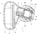
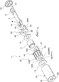
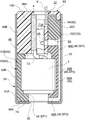
- FIG. 1 It is sectional drawing which shows the whole structure of the headset which concerns on 1st Embodiment. It is an exploded perspective view of the driver module which concerns on 1st Embodiment. It is a vertical sectional view in the axial direction of the driver module which concerns on 1st Embodiment.
- (A) is a perspective view of the driver holder according to the first embodiment, and (B) is a view of the driver holder viewed from the front side in the axial direction.
- (A) is a perspective view of the driver holder according to the second embodiment, and (B) is a view of the driver holder viewed from the front side in the axial direction.
- FIG. 11 (A), and (B) is a vertical sectional view of the driver module according to the fifth embodiment. Therefore, it is a figure corresponding to FIG. 11 (B).
- the headset 1 according to the first embodiment will be described with reference to FIGS. 1 to 4.
- the eardrum side of the ear canal is referred to as the anterior side
- the entrance side or the auricle side of the ear canal is referred to as the posterior side when the headset 1 is worn.
- the headset 1 has a hollow housing 10 containing functional components inside.
- the housing 10 is formed by fitting the front housing 12 and the rear housing 14.
- the front housing 12 is formed in a cylindrical shape having the outer shape of an oblique truncated cone as a whole, and its diameter is gradually reduced from the rear side to the front side. As a result, the front housing 12 has a shape protruding toward the eardrum side of the user.
- the front end portion of the front housing 12 is provided with an ear canal insertion portion 16 protruding from the top of the truncated cone portion toward the eardrum side.
- the ear canal insertion portion 16 is formed in a bottomed cylindrical shape with the anteroposterior direction as the axial direction, and a housing opening 18 for communicating the inside and outside of the front housing 12 is provided at the center of the bottom surface 16A constituting the front end portion.
- a driver module 9 which will be described later, is housed inside the ear canal insertion portion 16.
- the earpiece 20 is attached to the outer circumference of the ear canal insertion portion 16.
- the earpiece 20 is also called an eartip, an earpad, or an earcap, and is made of an elastic material such as silicone rubber.
- the earpiece 20 has a cylindrical portion 20A that is fitted to the outer periphery of the external auditory canal insertion portion 16.
- the cylindrical portion 20A is configured such that the fitting groove 21 provided on the inner circumference fits into the fitting projection 16B provided on the outer periphery of the external auditory canal insertion portion 16.
- a hemispherical cover-shaped close contact portion 20B that expands so as to cover the entire cylindrical portion 20A is integrally provided.
- the close contact portion 20B is configured to be in close contact with the wall surface of the user's ear canal and close the ear canal when the headset 1 is used.
- the rear housing 14 is formed in a dish shape with a shallow bottom open to the front side, and is arranged so as to close the rear opening of the front housing 12.
- the printed circuit board 2 is arranged in the accommodation space composed of the rear part of the front housing 12 and the rear housing 14.
- the printed circuit board 2 is a board on which electronic components necessary for controlling the headset 1 are mounted. For example, depending on the purpose of use of the headset 1, output control such as an output signal from the driver 3 described later, adjustment of the sensitivity of the microphone 4, etc., cancellation frequency band and level in noise canceling, and personal authentication by the headset are performed. Perform various controls in the case.
- the printed circuit board 2 is arranged in a posture in which the front-rear direction is substantially the plate thickness direction, and has mounting surfaces on both front and rear surfaces.
- the flexible board 6 connected to the driver module 9 via the connector 5 and the charging terminal 7 of the headset 1 are connected to the mounting surface on the front surface of the printed circuit board 2.
- the battery 8 is arranged behind the printed circuit board 2.
- driver module 9 Next, the configuration of the driver module 9 will be described in detail with reference to FIGS. 2 to 4.
- the driver holder 40, the driver 3, the microphone holder 60, and the microphone board 70 on which the microphone 4 is mounted are housed in the module case 30 forming the outer shell in this order from the front to the rear.
- the module case 30 is formed in the shape of a bottomed cylinder that opens toward the rear, and the inside and outside of the module case 30 are communicated with each other in the center of the bottom wall 32 constituting the front end portion.
- a module opening 34 is provided.
- the module opening 34 has substantially the same external dimensions as the housing opening 18, and is arranged coaxially.
- the module case 30 is formed by drawing, for example, a metal material such as iron or aluminum with a press machine. Further, the opening on the rear end side (the other end side in the axial direction) of the module case 30 is closed by the metal closing member 36.
- the module case 30 corresponds to the "holder insertion portion" in the present disclosure, and the driver holder 40 described later is inserted.
- the driver holder 40 is formed to be long with the front-rear direction as the longitudinal direction.
- the driver holder 40 is composed of a tubular portion 42 formed in a cylindrical shape as a whole.
- the driver 3 is housed inside the tubular portion 42.
- the driver holder 40 is made of an elastic material that can be elastically deformed.
- the driver holder 40 is formed of an elastomer material such as TPE (Thermoplastic elastomer) or TPU (Thermoplastic polyurethane).
- TPE Thermoplastic elastomer
- TPU Thermoplastic polyurethane
- the tubular portion 42 is formed in a cylindrical shape with the front-rear direction as the axial direction, and is open in the front-rear direction.
- the tubular portion 42 is press-fitted into the module case 30 and comes into close contact with the inner surface of the module case 30 to form the first sound path portion SP1 and the second sound path portion SP2.
- the first sound path portion SP1 is composed of an opening on the axial front end side (one side) of the tubular portion 42. More specifically, the first sound path portion SP1 is composed of a through hole 44 that penetrates the front wall 42A covering the front end of the tubular portion 42 in the front-rear direction.
- the first sound path portion SP1 is a sound path that allows the driver 3 and the user's ear canal to communicate with each other in a state where the tubular portion 42 is press-fitted into the module case 30. Further, the first sound path portion SP1 can adjust the volume of the first sound path portion SP1 and the volume in front of the driver 3 by adjusting the thickness dimension of the front wall 42A and the inner diameter dimension of the through hole 44. ing.
- the second sound path portion SP2 is composed of a groove portion 46 formed on the surface of the tubular portion 42.
- the second sound path portion SP2 communicates with the first sound path portion SP1 in a state where the tubular portion 42 is press-fitted into the module case 30, and the sound extended to the microphone 4 described later in the module case 30. It will be the way.
- the groove portion 46 is formed in a lateral groove portion 46A formed in the front wall 42A of the tubular portion 42, a first vertical groove portion 46B formed in the outer peripheral portion 42B, and a second extension portion 42C of the tubular portion 42, which will be described later.
- the vertical groove portion 46C is included.
- the lateral groove portion 46A extends from the peripheral edge portion of the through hole 44 formed in the front wall 42A along the radial direction of the tubular portion 42, and communicates with the first sound path portion SP1.
- the first vertical groove portion 46B is provided continuously with the lateral groove portion 46A at the radial outer end portion of the tubular portion 42, and extends along the axial direction of the tubular portion 42. From the rear end portion of the first vertical groove portion 46B, the second vertical groove portion 46C of the extension portion 42C is continuously provided.
- the extension portion 42C is provided at the end portion of the outer peripheral portion 42B on the rear end side (the other end side) in the axial direction.
- the extension portion 42C is a plate-shaped member extending axially rearward from the opening 48 provided at the rear end portion of the outer peripheral portion 42B, and the radial direction of the tubular portion 42 is the thickness direction.
- the extension portion 42C has a curved surface whose outer surface in the radial direction is continuous with the outer peripheral portion 42B, and is in close contact with the inner surface of the module case 30.
- a second vertical groove portion 46C provided continuously with the first vertical groove portion 46B is formed on the radial outer surface of the extension portion 42C.
- the second vertical groove portion 46C communicates with a side through hole 47 that penetrates the extension portion 42C in the thickness direction.
- the second vertical groove portion 46C communicates with the sound hole 4A of the microphone 4 through the side through hole 47 and through the through holes 64A and 70A formed in the microphone holder 60 and the microphone substrate 70, which will be described later.
- Ribs 50 protruding toward the module case 30 are integrally provided on the surface of the tubular portion 42.
- the rib 50 is composed of, for example, a triangular rib, and when the tubular portion 42 is press-fitted into the module case 30, the tip of the triangular rib elastically deforms and comes into close contact with the inner surface of the module case 30. That is, the rib 50 has a function of reducing the contact area between the surface of the tubular portion 42 and the inner surface of the module case 30 to reduce the frictional resistance at the time of press fitting. At the same time, it also has a function of ensuring the airtightness of the first sound path portion SP1 and the second sound path portion SP2.
- a plurality of ribs 50A are arranged on the outer peripheral portion 42B of the tubular portion 42.
- Each of the plurality of ribs 50A extends along the axial direction of the tubular portion 42 and is arranged at a predetermined interval in the circumferential direction of the outer peripheral portion 42B. Further, the ribs 50A are arranged in pairs on both sides of the first sound path portion SP1.
- the plurality of ribs 50A are portions that are elastically deformed at the initial stage of press fitting into the module case 30, but since they extend along the insertion direction of the tubular portion 42, the module case 30 and the tubular portion 42 The frictional resistance between them is effectively reduced.
- the rib 50A is in close contact with the inner surface of the module case 30 on both sides of the first vertical groove portion 46B to seal the second sound path portion SP2.
- the rib 50B extends along the circumferential direction of the outer peripheral portion 42B and connects the upper end portions of the ribs 50A.
- the rib 50B has the outer peripheral portion 42B in close contact with the inner surface of the module case 30 along the circumferential direction.
- the rib 50C is arranged on the radial outer surface of the extension portion 42C, extends so as to surround the periphery of the second vertical groove portion 46C, and extends at the peripheral portion of the second vertical groove portion 46C to form the inner surface of the module case 30. It is in close contact with.
- a driver pressing portion 52 is integrally provided on the axial rear end side (the other end side) of the tubular portion 42.
- the driver pressing portion 52 forms a peripheral edge portion of the opening 48, and projects radially inward from the outer peripheral portion 42B in an eaves shape.
- the driver accommodating portion DC is provided between the front wall 42A of the tubular portion 42 and the driver pressing portion 52.
- the driver 3 is housed in the driver accommodating portion DC so as to get over the driver pressing portion 52 while elastically deforming the driver pressing portion 52 to the front side. In the state where the driver 3 is accommodated, the inner surface of the driver accommodating portion DC is in close contact with the driver 3.
- the inner diameter (diameter of the inner peripheral surface) of the driver accommodating portion DC is formed to be slightly smaller than the outer diameter of the outer peripheral surface of the driver 3.
- the driver 3 is provided with a magnetic circuit, a diaphragm, and the like for generating an output signal in a cylindrical case whose axial direction is the front-rear direction, and a well-known structure can be used as appropriate.
- the diaphragm of the driver 3 is arranged on the front end side of the case, and outputs an acoustic signal into the user's ear canal via the first sound path portion SP1.
- a microphone holder 60 as a holder pressing portion is arranged behind the driver holder 40.
- the microphone holder 60 is a plate-shaped member bent in a substantially L-shape as a whole, and is arranged between the tubular portion 42 of the driver holder 40 and the closing member 36 in a state where the module case 30 is closed. ing.
- the microphone holder 60 is made of a resin material as an example.
- the microphone holder 60 has a lower wall portion 62 that comes into contact with the rear surface of the driver holder 40, and a vertical wall portion 64 that stands vertically rearward from the upper surface of the lower wall portion 62.
- the lower wall portion 62 that comes into contact with the rear surface of the driver holder 40 is provided with an opening 63 that penetrates the lower wall portion 62 in the axial direction (plate thickness direction) and communicates the inside and outside of the driver accommodating portion DC.
- the opening 63 is provided to release the back pressure generated when the diaphragm of the driver 3 vibrates to the rear space of the driver 3. Further, the opening 63 also serves as a wiring opening through which the wiring 72 connected to the driver 3 is inserted, as will be described later.
- the vertical wall portion 64 is in contact with the radial inner surface of the extension portion 42C of the driver holder 40.
- the rear end of the vertical wall portion 64 is pressed by the closing member 36 in a state where the module case 30 is closed.
- the lower wall portion 62 and the vertical wall portion 64 are configured to press the tubular portion 42 toward the front end side in the axial direction.
- a microphone fixing portion 66 is provided on a surface opposite to the surface in contact with the extension portion 42C.
- the microphone substrate 70 is fixed to the microphone fixing portion 66 by a method such as fixing with a pressure-sensitive adhesive or fitting a claw.
- the microphone substrate 70 is arranged in a vertical position in which the direction orthogonal to the axial direction of the module case 30 is the plate thickness direction, and the microphone 4 is mounted on the mounting surface facing the inner surface of the module case 30.
- a wiring 72 extending from the rear of the driver 3 is connected to the microphone board 70.
- the wiring 72 is connected to the microphone substrate 70 through the opening 63 formed in the lower wall portion 62 of the microphone holder 60.
- the microphone substrate 70 is not essential in the present disclosure, and the microphone may be directly fixed to the microphone fixing portion 66.
- the microphone 4 is suitable for the functions of the headset 1, for example, noise canceling, personal authentication, pulse wave detection, and the like.
- a microphone 4 is used as a device that collects sound in the ear canal, such as a feedback microphone for noise cancellation, and a vibration sensor that measures vibration, pressure change, and the like in the audible and inaudible frequency bands in the ear canal.
- the sound collecting sound holes 4A provided corresponding to the internal diaphragm are opened in the direction orthogonal to the axial direction of the module case 30. Has been done.
- the sound hole 4A is communicated with the side through hole 47 provided in the extension portion 42C of the driver holder 40 by the through holes 64A and 70A formed in the vertical wall portion 64 of the microphone holder 60 and the microphone substrate 70.
- the sound (vibration) in the ear canal reaches the microphone 4 via the second sound path portion SP2.
- the microphone 4 is arranged inside the module case 30 in front of and behind the tubular portion 42 of the driver holder 40 along the axial direction.
- the module case 30 can be miniaturized in the radial direction, and the entire module case 30 can be arranged in the ear canal.
- the microphone board 70 and the printed circuit board 2 described above are connected by a flexible board 6.
- the flexible substrate 6 is formed in the shape of a long sheet, and is connected to the rear end of the microphone substrate 70 as shown in FIG.
- the other end of the flexible substrate 6 is inserted through the insertion portion 37 of the closing member 36 and protrudes to the outside of the module case 30.
- the flexible substrate 6 is housed in the rear housing space of the housing 10 in a bent state (see FIG. 1).
- the driver module 9 having the above configuration is assembled as follows. After the driver 3 is housed in the driver holder 40, the microphone holder 60, the microphone board 70, the microphone 4 and the flexible board 6 which are pre-assembled to the driver holder 40 are fixed. Then, the driver 3 and the microphone board 70 are connected by the wiring 72. After that, these are integrally press-fitted into the inside of the module case 30, and the rear end opening of the module case 30 is closed by the closing member 36 to complete the assembly (assembly) of the driver module 9.
- a sheet-shaped pressure-sensitive adhesive 74 is provided between the module case 30, the driver holder 40, and the driver holder 40 and the microphone holder 60, and the two are joined to each other.
- the pressure-sensitive adhesive 74 is provided to stabilize the positioning of each component during module assembly, but is not essential from the viewpoint of ensuring the airtightness inside the module case 30. That is, in this embodiment, the airtightness inside the module case 30 can be ensured by utilizing the elastic force of the driver holder 40. Therefore, from the viewpoint of reducing the number of parts, the module case 30 may not be provided with the pressure-sensitive adhesive 74.
- the headset 1 has been described above. However, when the headset 1 has a noise canceling function, noise or the like entering the ear canal from the outside is a first sound path formed in the module case 30. It reaches the microphone 4 through the section SP1 and the second sound path section SP2. The noise that reaches the microphone 4 is converted into an electric signal by the microphone 4. The electric signal corresponding to the converted noise is input to the control unit of the printed circuit board 2, and a noise canceling signal having the opposite phase is generated. Noise canceling is possible by converting this noise canceling signal into an acoustic signal and outputting it from the driver 3.
- the headset 1 has a biometric authentication function, for example, an acoustic signal is output from the driver 3 by utilizing individual differences in the shape of the ear canal of an individual, and a response signal generated in the ear canal is acquired by the microphone 4. Then, the individual can be authenticated by performing frequency analysis of the response signal acquired by the microphone 4 in the control unit.
- a biometric authentication function for example, an acoustic signal is output from the driver 3 by utilizing individual differences in the shape of the ear canal of an individual, and a response signal generated in the ear canal is acquired by the microphone 4. Then, the individual can be authenticated by performing frequency analysis of the response signal acquired by the microphone 4 in the control unit.
- the driver holder 40 has a tubular portion 42 formed in a cylindrical shape by an elastic material, and the driver 3 is housed inside the tubular portion 42. Further, the tubular portion 42 is configured to be press-fitted into the holder insertion portion, that is, the module case 30 inside the housing 10. As a result, the driver 3 arranged inside the housing 10 is held by the driver holder 40.
- the through hole 44 provided on the axial front end side (one end side) of the tubular portion 42 constitutes the first sound path portion SP1 that communicates the driver 3 and the user's ear canal.
- the acoustic signal output by the driver 3 is radiated to the user's ear canal (outside the housing 10) via the first sound path portion SP1.
- a second sound path portion SP2 is formed on the surface of the tubular portion 42.
- the second sound path portion SP2 is composed of a groove portion 46 formed on the surface of the tubular portion 42, communicates with the first sound path portion SP1, and is arranged on the outside (rear side) of the tubular portion 42. It extends to the microphone 4 that was used. As a result, the acoustic signal in the user's ear canal propagates to the microphone 4 via the first sound path portion SP1 and the second sound path portion SP2.
- each sound path portion by changing the shape of the driver holder 40, so that it is not necessary to change the design of the housing 10.
- these sound path portions (SP1 and SP2) are in a sealed state by press-fitting the tubular portion 42 into the module case 30. Therefore, it is easy to assemble the second sound path portion SP2 for the microphone while ensuring the airtightness.
- the second sound path portion SP2 is provided integrally with the driver holder 40, the positional relationship between the driver 3 and the microphone 4 is stable. Therefore, it is possible to suppress variations due to assembly.
- the driver holder 40 is formed of an elastic material, it can be easily press-fitted into the module case 30 by elastically deforming the tubular portion 42, and the assembling property can be improved. can. Further, since the driver 3 is housed in the driver holder 40, the shock absorbing performance is enhanced.
- ribs 50A, 50B, 50C protruding from the surface are formed on the surface of the tubular portion 42, and the tubular portion 42 is a module while elastically deforming the ribs 50A, 50B, 50C. It is press-fitted into the case 30. As a result, the frictional resistance when the tubular portion 42 is press-fitted into the module case 30 is reduced, so that workability during manufacturing is improved.
- the driver 3 is pressed toward the front side (one side) in the axial direction of the tubular portion 42 by the elastic force of the driver pressing portion 52.
- the airtightness between the driver 3 and the tubular portion 42 is effectively enhanced in the vicinity of the first sound path portion SP1, which in turn contributes to the improvement of the airtightness of the first sound path portion SP1.
- the manufacturing process by overcoming the driver pressing portion 52, it is possible to clearly confirm by the operator's visual and tactile sense that the driver 3 is housed in an appropriate position in the tubular portion 42. , Product assembly accuracy and workability are improved.
- the driver 3 and the first sound path portion SP1 and the first sound path portion SP1 are formed by press-fitting the driver holder 40 into the module case 30.
- the two sound path portions SP2 can be easily modularized.
- the microphone holder 60 as a holder pressing portion is arranged between the closing member 36 of the module case 30 and the tubular portion 42, and the driver holder 40 is pressed toward the front end side (one end side) in the axial direction. ing. Therefore, by closing the module case 30, the cylindrical portion 42 can be pressed toward the front end side in the axial direction, so that the positional relationship between the driver 3 and the microphone 4 can be stabilized, and variations due to assembly can be reduced.
- the microphone holder 60 as the holder pressing portion is provided with the microphone fixing portion 66, the microphone 4 is arranged in the module case 30.
- the main functional parts of the headset 1 such as the driver 3, the microphone 4, and the sound path part can be modularized and managed as an assembly, so that the product manageability is excellent.
- the installation work on the housing 10 side can be simplified.
- the module case 30 (driver module 9) is installed in the housing 10 by simply joining the bottom wall 32 of the module case 30 to the bottom surface 16A of the ear canal insertion portion 16 using the pressure-sensitive adhesive 74. Can be done.
- modularizing the driver 3 and the microphone 4 with the module case 30 it is possible to use them together with a plurality of products having different shapes and the like, and it is excellent in versatility.
- the microphone 4 by arranging the microphone 4 and the microphone substrate 70 in a vertical position, the microphone 4 can be arranged back and forth along the cylindrical portion 42 and the axial direction.
- the external dimensions of the module case 30 can be designed according to the external dimensions of the driver 3 (driver holder 40), and the driver module 9 is miniaturized in the radial direction.
- the module case is enlarged in the radial direction in order to secure the width of the microphone substrate as compared with the configuration in which the microphone is arranged in the vertical posture.
- the module case 30 is effectively prevented from being enlarged in the radial direction by arranging the microphones in a vertical position.
- the thickness of the side wall and the bottom wall of the case is reduced as compared with the case where the module case 30 is made of other materials such as resin. It can contribute to miniaturization.
- the driver module 9 is arranged inside the external auditory canal insertion portion 16 of the housing 10, it is possible to expand the storage space for other parts inside the housing 10. This makes it possible to increase the size of the battery and increase the battery capacity of the headset 1, for example, by expanding the storage space of the battery.
- the microphone 4 since the microphone 4 is arranged behind the driver 3, the microphone 4 does not interfere with the acoustic output of the driver 3, and the inconvenience that the desired acoustic characteristics cannot be obtained is solved. Will be done.
- the driver module 9 is arranged inside the external auditory canal insertion portion 16, the volume in front of the driver 3 can be reduced.
- the volume in front of the driver is the volume of the driver's anterior chamber formed between the driver and the ear canal inside the housing. That is, in the present embodiment, since the volume in front of the driver can be reduced, it is possible to suppress the attenuation of the high frequency characteristics in the ear canal.
- the driver holder 40 according to the first embodiment has a second sound path portion SP2 formed in a single groove shape as a whole on the surface of the tubular portion 42.
- the driver holder 80 according to the second embodiment constitutes the second sound path portion SP2 with a plurality of groove portions 82 formed on the surface of the tubular portion 42 and communicating with each other. It is characterized by points.
- Other configurations are the same as those in the first embodiment. In this embodiment, the same components as those in the first embodiment described above will be assigned the same number and the description thereof will be omitted.
- the plurality of groove portions 82 constituting the second sound path portion SP2 are continuously provided with five lateral groove portions 82A formed on the front wall 42A of the tubular portion 42 and each lateral groove portion 82A, and are provided in the tubular portion 42. It has five first flutes 82B formed in the outer peripheral portion 42B. These horizontal groove portions 82A and the first vertical groove portion 82B have a configuration corresponding to the horizontal groove portion 46A and the first vertical groove portion 46B in the first embodiment.
- Each of the five lateral groove portions 82A extends radially outward from the peripheral edge portion of the through hole 44 formed in the center of the front wall 42A, and is arranged radially as a whole when viewed from the axial direction. ing.
- the five first vertical groove portions 82B are continuously formed at the radial outer end portion of each lateral groove portion 82A, and the surface of the outer peripheral portion 42B extends along the axial direction.
- the five first flutes 82B are arranged at predetermined intervals along the circumferential direction of the outer peripheral portion 42B.
- a circumferential groove portion 82C extending on the surface of the outer peripheral portion 42B along the circumferential direction is formed.
- the circumferential groove 82C connects the rear ends of the five first vertical grooves 82B in the circumferential direction, and communicates with each of the first vertical grooves 82B.
- one second vertical groove portion 82D is formed behind the circumferential groove portion 82C.
- the second vertical groove portion 82D is formed on the surface of the extension portion 42C of the tubular portion 42.
- the second vertical groove portion 82D extends axially rearward from the circumferential groove portion 82C and communicates with the side through hole 47 of the extension portion 42C.
- the second vertical groove portion 82D has a configuration corresponding to the second vertical groove portion 46C in the first embodiment.
- the sound in the external auditory canal of the user is the first sound path portion SP1, the lateral groove portion 82A, the first vertical groove portion 82B, the circumferential groove portion 82C, and the second vertical groove portion 82D in this order. And reaches the sound hole 4A of the microphone 4.
- the driver holder 80 having the above configuration basically follows the configuration of the driver holder 40 according to the first embodiment, the same operation and effect can be obtained. Further, in the present embodiment, since a plurality of groove portions 82 (82A, 82B, 82C, 82D) are formed on the surface of the tubular portion 42 in order to form the second sound path portion SP2, these groove portions 82 are formed. The shock absorbing performance of the tubular portion 42 is enhanced by this. This improves the impact resistance of the driver 3.
- the cross-sectional area of the second sound path portion SP2 can be easily changed, and the acoustic signal of the microphone can be adjusted to a desired high frequency characteristic. That is, in the second embodiment, five lateral groove portions 82A and first vertical groove portions 82B are formed on the front wall 42A and the outer peripheral portion 42B of the tubular portion 42, respectively.
- the present disclosure is not limited to this, and the cross-sectional area of the second sound path portion SP2 can be changed by changing the number of the horizontal groove portion 82A and the first vertical groove portion 82B and the individual cross-sectional areas as necessary.
- the number of the horizontal groove portions 82A and the first vertical groove portions 82B may be one or more, and can be increased or decreased as appropriate.
- the acoustic signal of the microphone 4 is set to a desired height. It can be adjusted to the regional characteristics.
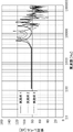
- FIG. 6 shows the relative frequency characteristics (relative difference) of the driver sound source at the microphone 4 positions of the second and third embodiments based on the first embodiment.
- the horizontal axis shows the frequency [Hz] of the acoustic signal output from the driver 3
- the vertical axis shows the sound pressure level [dB] at the microphone 4 position.
- the horizontal groove portion 46A, the first vertical groove portion 46B, and the second vertical groove portion 46C are formed one by one on the surface of the tubular portion of the driver holder. That is, in the first embodiment, the second sound path portion SP2 is formed with the same configuration as the driver holder 40 of the first embodiment (see FIG. 4).
- Example 2 In the headset of the second embodiment, five horizontal groove portions 82A, five first vertical groove portions 82B, one circumferential groove portion 82C, and one second vertical groove portion are formed on the surface of the tubular portion of the driver holder. 82D was formed. That is, in the second embodiment, the second sound path portion SP2 is formed with the same configuration as the driver holder 80 of the second embodiment (see FIG. 5).
- Example 3 In the headset of the third embodiment, ten horizontal groove portions 82A, ten first vertical groove portions 82B, one circumferential groove portion 82C, and one second vertical groove portion are formed on the surface of the tubular portion of the driver holder. 82D was formed. That is, in the third embodiment, the basic structure is the same as that of the driver holder 80 of the second embodiment, but the lateral groove portion 82A and the first vertical groove portion 82B formed on the front wall 42A and the outer peripheral portion 42B of the tubular portion 42.
- the second sound path portion SP2 is formed by arranging ten of them at equal intervals along the circumferential direction.
- the frequency characteristic at the microphone 4 position can be adjusted in the high frequency region.
- the acoustic signal of the microphone can be adjusted to a desired high frequency characteristic.
- the cross-sectional area of the second sound path portion SP2 can be easily secured. Therefore, by reducing the height dimension (diametrical dimension) of the single groove portion 82, the outer diameter dimension of the tubular portion 42 can be further reduced, and the module case 30 can be miniaturized in the radial direction. Can be done.
- the microphone fixing portion 96 is integrally provided with the extension portion 94 of the driver holder 92. That is, the configuration corresponding to the microphone fixing portion 66 of the driver holder 40 and the microphone holder 60 in the first embodiment is integrally formed. Further, the closing member 98 is provided with a holder pressing portion 98B. Other configurations are the same as those in the first embodiment. In this embodiment, the same components as those in the first embodiment described above will be assigned the same number and the description thereof will be omitted.
- the driver holder 92, the driver 3, and the microphone board 70 on which the microphone 4 is mounted are housed in the module case 30 forming the outer shell of the driver module 90 in this order from the front to the rear. Further, the rear end opening of the module case 30 is closed by a resin closing member 98.
- the driver holder 92 is integrally provided with an extension portion 94 on the axial rear end side (the other end side) of the tubular portion 42.
- the extension portion 94 is a plate-shaped member that constitutes a part of the tubular portion 42 and is extended rearward from the axial rear end portion of the outer peripheral portion 42B. Similar to the extension portion 42C of the first embodiment, the extension portion 94 has a second vertical groove portion 46C forming the second sound path portion SP2 formed on the outer surface in the radial direction.
- a microphone fixing portion 96 is provided on the inner surface of the extension portion 94 in the radial direction, and the microphone substrate 70 is fixed by a method such as fixing with a pressure-sensitive adhesive or fitting a claw. Further, the extension portion 94 is provided with a side through hole 95 for communicating the second vertical groove portion 46C and the sound hole 4A of the microphone 4.
- the closing member 98 has a lid portion 98A that closes the rear end opening of the module case 30, and a holder pressing portion 98B that hangs down from the case inner surface of the lid portion 98A to the front side in the axial direction.
- the holder pressing portion 98B is formed in a block shape, and with the module case 30 closed, the front end portion presses the tubular portion 42 axially forward. Further, the radial inner side surface of the holder pressing portion 98B presses the microphone 4 and the microphone substrate 70 against the extension portion 94 side via the cushion material 100 to support the extension portion 94.
- the position of the driver 3 and the microphone 4 is stabilized by the closing member 98, and the assembling property is improved.
- the airtightness of the first sound path portion SP1 and the second sound path portion SP2 can be enhanced.
- the driver holder 92 having the above configuration basically follows the configuration of the driver holder 40 according to the first embodiment, the same operation and effect can be obtained. Further, in the present embodiment, the microphone fixing portion 96 is integrally provided with the driver holder 92 so that the microphone holder, which is separate from the driver holder, is not required. Therefore, the number of parts of the driver module 90 is increased. And the assembly man-hours can be reduced. Further, since the holder pressing portion 98B is integrally provided on the closing member 98, the positions of the driver 3 and the microphone 4 are stable. As a result, the assemblability of the driver module 90 can be improved.
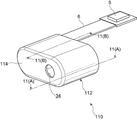
- the driver module 110 of the fourth embodiment shown in FIGS. 9 to 11 is characterized in that the microphone 4 is arranged on the side of the driver 3 inside the module case 112.
- the same components as those in the first embodiment are designated by the same numbers, and the description thereof will be omitted.
- the module case 112 is formed flat in the left-right direction (direction orthogonal to the axial direction), and is formed in a bottomed tubular shape open to the rear side in the axial direction.
- a module opening 34 for communicating the inside and outside of the module case 112 is provided on one end side of the bottom wall 114 of the module case 112 in the left-right direction. Further, inside the module case 112, a tubular driver holder 116 formed flat in the left-right direction is press-fitted.
- the driver holder 116 is formed in a tubular shape in which one end side in the left-right direction is open in the front-rear direction in the axial direction, and the inside is a driver accommodating portion DC.
- the driver 3 is inserted into the driver accommodating portion DC through the opening 48 on the rear end side in the axial direction provided corresponding to the driver accommodating portion DC.
- the driver pressing portion 52 is integrally provided in the opening portion 48.
- the opening on the front end side in the axial direction provided corresponding to the driver accommodating portion DC is composed of a through hole 44 that penetrates the front wall 116A of the driver holder 116 in the axial direction, and the through hole 44 is the first. It constitutes one sound path section SP1.
- a concave accommodating portion is formed on the outer peripheral portion 116B on the other end side in the left-right direction of the driver holder 116, and is used as a microphone fixing portion 118.
- a microphone substrate 70 on which the microphone 4 is mounted is fixed to the microphone fixing portion 118.
- the microphone board 70 and the above-mentioned driver 3 are connected by a wiring 72 extending in the left-right direction behind the driver holder 116.
- One end of the flexible substrate 6 is connected to the microphone substrate 70.
- the other end of the flexible substrate 6 is inserted into the insertion portion 37 of the closing member 120 that closes the module case 112 from the rear, and protrudes to the outside of the module case 112.
- the microphone substrate 70 may not be provided, and the microphone may be directly fixed to the microphone fixing portion 118.
- a sound hole 4A opened on the microphone fixing portion 118 side is formed on the lower surface of the microphone 4.
- the sound hole 4A communicates with the second sound path portion SP2 through the through hole 70A penetrating the microphone substrate 70 in the plate thickness direction.
- the second sound path portion SP2 is integrally formed with the driver holder 116.
- the second sound path portion SP2 includes a single lateral groove portion 122A formed on the surface of the front wall 116A of the driver holder.
- the lateral groove portion 122A extends from the peripheral edge portion of the through hole 44 to the other end side in the left-right direction.
- the lateral groove portion 122A has a sound path communicating with the first sound path portion SP1 by the driver holder 116 being press-fitted into the module case 112 and the front wall 116A of the driver holder 116 abutting on the bottom wall 114 of the module case 112.
- the second sound path portion SP2 includes a horizontal hole portion 122B continuously provided at the other end of the horizontal groove portion 122A in the left-right direction and a vertical hole portion 122C continuously provided at the rear end portion of the horizontal hole portion 122B.
- the horizontal hole portion 122B extends from the front wall 116A of the driver holder 116 to the rear side in the axial direction and is connected to the lower end portion of the vertical hole portion 122C.
- the vertical hole portion 122C penetrates the microphone fixing portion 118 side of the driver holder 116 and communicates with the sound hole 4A of the microphone 4.
- the second sound path portion SP2 is composed of the lateral groove portion 122A, the horizontal hole portion 122B, and the vertical hole portion 122C, and extends from the first sound path portion SP1 to the microphone 4. As a result, the sound outside the module case 112 reaches the microphone 4 via the first sound path portion SP1 and the second sound path portion SP2.
- the driver holder 116 is press-fitted into the module case 112 to form the second sound path portion SP2 for the microphone, so that the second sound path portion SP2 is formed. It is possible to easily change and secure the airtightness and improve the assembling property.
- the module case 112 and the driver holder 116 can be miniaturized in the axial direction.
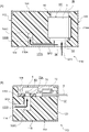
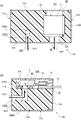
- the driver module 130 of the fifth embodiment shown in FIGS. 12A and 12B basically follows the configuration of the driver module 110 of the fourth embodiment, but the second sound path portion SP2.
- the configuration is different in that the first sound path portion SP1 and the first sound path portion SP1 are not communicated with each other.
- the same components as those in the fourth embodiment are designated by the same number and the description thereof will be omitted.
- a module opening 34 is formed on one end side in the left-right direction of the bottom wall 114, and a sound path module opening 132 is formed on the other end side in the left-right direction.
- the sound path module opening 132 is composed of a through hole penetrating the bottom wall 114 in the plate thickness direction, and communicates the outside of the module case 112 with the second sound path portion P2.
- the second sound path portion SP2 is provided on the side of the first sound path portion SP1 for the driver, and is composed of a horizontal hole portion 122B and a vertical hole portion 122C that penetrate the front wall 116A and the outer peripheral portion 116B of the driver holder 116. There is.
- the configuration of the fifth embodiment basically follows the configuration of the fourth embodiment, the same action and effect can be obtained. Further, on the surface of the driver holder 116, the surface shape of the front wall 116A, which affects the airtightness of the first sound path SP1 and the second sound path portion SP2, can be simplified, so that the contact surface with the module case 112 can be simplified. Is stable and the airtightness of each sound path is improved.
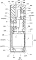
- the driver module 200 according to the sixth embodiment will be described with reference to FIGS. 13 and 14.
- the same components as those in the first embodiment described above will be assigned the same number and the description thereof will be omitted.
- the driver module 200 according to the sixth embodiment is characterized in that two microphones 400A and 400B can be accommodated inside the module case 210.
- a driver holder 220, a driver 3, a first microphone holder 230, a first microphone board 70A on which a first microphone 400A is mounted, a second microphone holder 240, and a second microphone holder are mounted inside the module case 210.
- the second microphone substrate 70B on which the microphone 400B is mounted is housed in this order from the front to the rear.
- the module case 210 is formed in a bottomed cylindrical shape that opens to the rear side in the axial direction, and a module opening 214 that communicates the inside and outside of the module case 210 is provided in the center of the bottom wall 212 of the module case 210. ing. Further, the module case 210 has a sound path accommodating portion 216 formed by raising a part of the outer periphery radially outward.
- the driver holder 220 is formed in a cylindrical shape that opens in the front-rear direction in the axial direction, and is press-fitted from the rear opening of the module case 210.
- the driver holder 220 basically follows the configuration of the driver holder 40 of the first embodiment, and is an extension integrally provided at the cylindrical portion 222 and the rear end portion of the cylindrical portion 222. It has a part 224.
- a first sound path portion SP1 is formed in the front wall 222A of the tubular portion 222 by a through hole 44 formed through the tubular portion 222.
- the second sound path portion SP2 is formed by the groove portion 46 formed on the surface of the tubular portion 222 and the extension portion 224 so as to communicate with the first sound path portion. Since the configurations of the first and second sound path portions SP1 and SP2 are the same as those of the first embodiment, detailed description thereof will be omitted.
- the outer peripheral portion where the second sound path portion SP2 is formed is raised in the radial direction, and is formed to be thicker than the other portions. This thick portion is accommodated in the sound path accommodating portion 216 of the module case 210 when the driver holder 220 is press-fitted into the module case 210.
- the driver holder 220 has a thick second sound path portion SP2, and the outer diameter is reduced by thinning the portion other than the second sound path portion SP2 to reduce the size. ..
- a rib 50 surrounding the second sound path portion SP2 is further formed on the surface of the driver holder 220, and the tip of the rib 50 is elastically deformed to be in close contact with the inner surface of the sound path accommodating portion 216. As a result, the second sound path portion SP2 having excellent airtightness is formed.
- the driver 3 is inserted into the driver accommodating portion DC formed inside the tubular portion 222 of the driver holder 220 from the opening 226 on the rear end side of the tubular portion 222, and the driver 3 is inserted.
- the first microphone holder 230 is arranged on the rear side.
- the first microphone holder 230 basically follows the configuration of the microphone holder 60 of the first embodiment, and has a lower wall portion 232 that abuts on the rear surface of the driver holder 220 and a shaft from the upper surface of the lower wall portion 232.
- a plate-shaped member bent in a substantially L-shape by a vertical wall portion 234 erected on the rear side in the direction is formed.
- the lower wall portion 232 has an opening 236 formed through the opening in the axial direction (plate thickness direction), and the wiring 72 connected to the rear surface of the driver 3 is pulled out to the rear side through the opening 236.
- the extension portion 224 of the driver holder 220 abuts on the outer surface of the vertical wall portion 234 facing the inner surface of the module case 210, and forms a substantially flush curved surface with the extension portion 224.
- a first microphone fixing portion 66A is provided on the inner surface of the vertical wall portion 234 provided on the opposite side of the outer surface.
- the first microphone substrate 70A is fixed to the first microphone fixing portion 66A by using a pressure-sensitive adhesive.
- the first microphone board 70A is arranged in a vertical position like the microphone board 70 of the first embodiment, and the first microphone board 70A is on the mounting surface opposite to the first microphone fixing portion 66A in the first microphone board 70A.
- a microphone 400A is mounted.
- the sound hole of the first microphone 400A is formed through a through hole formed through each of the first microphone substrate 70A, the vertical wall portion 234 of the first microphone holder 230, and the extension portion 224 of the driver holder 220 (both are omitted in reference numerals). 2 It communicates with the sound path section SP2.
- the first microphone 400A is used, for example, for feedback type noise canceling.
- the first microphone board 70A is connected to a long sheet-shaped first flexible board 6A, and is electrically connected to the printed circuit board 2 in the housing 10 via a connector 5 provided at the tip of the first flexible board 6A. ing.
- the second microphone holder 240 is arranged on the rear side of the first microphone holder 230.
- the second microphone holder 240 also follows the configuration of the microphone holder 60 of the first embodiment in the basic configuration portion like the first microphone holder 230, and is abbreviated by the lower wall portion 242 and the vertical wall portion 244. It forms an L-shaped bent plate-shaped member.
- the second microphone holder 240 is arranged in a posture opposite to that of the first microphone holder 230 in the front-rear direction, and is housed inside the module case 210 alternately with the first microphone holder 230.
- the vertical wall portions 234 and 244 of the first and second microphone holders 230 and 240 are arranged to face each other in the module case 210.
- the lower wall portion 242 of the second microphone holder 240 comes into contact with the rear surface of the vertical wall portion 234 of the first microphone holder 230, and the lower wall portion 242 closes the opening on the rear end side of the module case 210.
- the lower wall portion 242 has two insertion portions 246 for inserting a first flexible substrate 6A connected to the first microphone substrate 70A and a second flexible substrate 6B connected to the second microphone substrate 70B described later. It is formed.
- a sheet-shaped gasket 250 abuts on the outer surface of the module case 210 facing the inner surface of the vertical wall portion 244, forming a curved surface substantially flush with the outer surface of the vertical wall portion 244.
- the gasket 250 is formed by using the same elastic material as the driver holder 220, and in this embodiment, an elastomer material such as TPE or TPU is used as an example.
- the gasket 250 is arranged in a state of being press-fitted between the vertical wall portion 244 of the second microphone holder 240 and the module case 210.
- the gasket 250 forms a sealed third sound path portion SP3 that communicates the inside and outside of the module case 210 by bringing both sides into close contact with the outer surface of the vertical wall portion 244 and the inner surface of the module case 210.
- the third sound path portion SP3 is composed of a through hole 252 formed through the gasket 250.
- the through hole 252 is arranged coaxially with the through hole 218 formed on the outer periphery of the module case 210, so that the inside and outside of the module case 210 communicate with each other on the outside of the user's ear canal.
- a rib 50 surrounding the third sound path portion SP3 is formed on the surface of the gasket 250, and the tip of the rib 50 is elastically deformed and is in close contact with the inner surface of the module case 210.
- the second microphone fixing portion 66B is provided on the inner side surface provided on the opposite side of the outer surface of the second microphone holder 240.
- the second microphone substrate 70B is fixed to the second microphone fixing portion 66B by using a pressure-sensitive adhesive.
- the second microphone substrate 70B is arranged in a vertical position like the first microphone substrate 70A, and is arranged on the rear side of the first microphone substrate 70A.
- the second microphone 400B is mounted on the mounting surface opposite to the second microphone fixing portion 66B.
- the sound hole of the second microphone 400B communicates with the third sound path portion SP3 through a through hole (both not shown) formed through the vertical wall portion 244 of the second microphone substrate 70B and the second microphone holder 240. ing.
- the second microphone 400B is used, for example, for feedforward noise canceling.
- the second microphone board 70B is connected to a long sheet-shaped second flexible board 6B, and is electrically connected to the printed circuit board 2 in the housing 10 via a connector 5 provided at the tip of the second flexible board 6B. ing.
- the driver 3 is housed in the driver holder 220 in advance, and the first microphone board 70A, the first microphone 400A, and the first flexible board 6A are fixed to the first microphone holder 230.
- the driver holder 220 and the first microphone holder 230 are fixed with the pressure-sensitive adhesive 74, and are press-fitted into the module case 210 in an assembled state.
- the second microphone holder 240 in which the second microphone substrate 70B, the second microphone 400B, the second flexible substrate 6B and the gasket 250 are fixed in advance is inserted into the module case 210, and the module case 210 is inserted by the second microphone holder 240. Assembly is completed by closing the opening on the rear end side.
- the pressure-sensitive adhesive 74 is also arranged between the module case 210 and the driver holder 220.
- the driver module 200 having the above configuration basically follows the configuration of the driver module 9 of the first embodiment, the same operation and effect can be obtained. Further, in the present embodiment, the first microphone 400A used for the feedback type noise canceling and the second microphone 400B used for the feed forward type noise canceling are modularized integrally with the driver 3 to perform noise canceling. Ring performance can be improved.
- the first microphone holder 230 and the second microphone holder 240 are composed of substantially L-shaped plate-shaped members arranged in positions opposite to each other, and are alternately arranged in the module case 210. It is contained. As a result, the accommodation space of the first and second microphones 400A and 400B can be reduced in the axial direction, and the module case 210 can be downsized.
- the first microphone 400A and the second microphone 400B are arranged side by side in the module case 210, but the present invention is not limited to this, and the first microphone 400A and the second microphone 400B face each other. It is also possible to further reduce the size of the module case 210 in the axial direction by arranging the module case 210.
- the first microphone 400A is used for noise canceling, but the present invention is not limited to this, and it may be used as a vibration sensor for measuring vibration, pressure change, etc. in the audible and inaudible frequency bands in the ear canal. good.
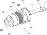
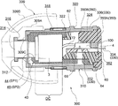
- driver module 300 according to the seventh embodiment and the headset 302 using the driver module 300 will be described with reference to FIGS. 15 to 19.
- the same components as those in the first embodiment described above will be assigned the same number and the description thereof will be omitted.
- the driver module 300 according to the seventh embodiment is characterized in that a part of the module case 310 is exposed from the housing 304 and arranged.
- the headset 302 has a hollow housing 304 containing functional parts inside.
- the housing 304 is formed by fitting the front housing 304A and the rear housing 304B.
- the front housing 304A is formed in a cylindrical shape having an outer shape of a truncated cone as a whole, and a housing opening 306 for communicating the inside and outside of the front housing 304A is provided at the top of the truncated cone.
- the driver module 300 is inserted into the housing opening 306.
- the rear housing 304B is formed in a dish shape with a shallow bottom open to the front side, and is arranged so as to close the rear opening of the front housing 304A.
- a box-shaped inner housing 308 opened to the front side is accommodated, and the battery 8 is held inside the inner housing 308.
- the first printed circuit board 2A is arranged on the front side of the inner housing 308, and the second printed circuit board 2B is arranged on the rear side of the inner housing 308.
- the first and second printed circuit boards 2A and 2B are arranged in such a posture that the plate thickness direction is substantially in the front-rear direction, and electronic components necessary for controlling the headset 302 are mounted on the mounting surfaces on both sides.
- the first printed circuit board 2A arranged on the front side of the inner housing 308 includes a charging terminal 7 of the headset 302 (not shown in FIG. 15) and a board assembly 330 connected to the driver module 300 via the connector 5. , Are connected.
- a module case 310 forming the outer shell of the driver module 300 is inserted into the housing opening 306 formed at the front end of the front housing 304A.
- the module case 310 is formed in a bottomed cylindrical shape that opens toward the rear, and a module opening 314 that communicates the inside and outside of the module case 310 is provided in the center of the bottom wall 312 that constitutes the front end portion. There is.
- the tip of the module case 310 projects forward of the front housing 304A and is located in the user's ear canal.
- the earpiece 309 is attached to the tip end portion (front end portion) of the module case 310.
- the earpiece 309 has a cylindrical portion 309A fitted on the outer periphery of the module case 310, and a hemispherical cover-shaped close contact portion 309B integrally provided at the tip of the cylindrical portion 309A.
- a first groove 316 formed in an annular shape along the circumferential direction is formed at the tip of the module case 310, and a fitting protrusion 309C provided on the inner circumference of the cylindrical portion 309A of the earpiece 309 in the first groove 316. Is fitted and the earpiece 309 is mounted on the module case 310.
- an annular second groove 318 is formed in the middle portion of the module case 310.
- a vent hole 319 (see FIG. 17) for communicating the inside and outside of the module case 310 is formed in the second groove 318, and the air pressure inside the module case 310 is adjusted to optimize the drive of the driver 3. ..
- An annular vent cover 322 made of a mesh material is attached to the second groove 318 to prevent external foreign matter from entering through the vent hole 319.
- an annular third groove 320 is formed at the rear end of the module case 310.
- a board assembly 330 on which a driver holder 40, a driver 3, a microphone holder 60, and a microphone 4 are mounted is housed in this order from the front to the rear, and the module case 310.
- the opening on the rear end side is closed by the closing member 350. Since the configurations of the driver holder 40, the driver 3, and the microphone holder 60 are the same as those in the first embodiment, detailed description thereof will be omitted.
- the substrate assembly 330 is formed by connecting a plate-shaped printed circuit board and a sheet-shaped flexible substrate, and has a first substrate portion 332, a second substrate portion 334, and a third.
- a board portion 336 and the like are provided.
- the first substrate portion 332 is composed of a plate-shaped printed circuit board, and is fixed to the microphone fixing portion 66 of the microphone holder 60.
- the first substrate portion 332 is arranged in the module case 310 in a vertical posture as in the microphone substrate 70 of the first embodiment.
- the microphone 4 is mounted on the mounting surface opposite to the microphone fixing portion 66.
- the sound hole of the microphone 4 is a second sound path portion through a through hole formed through each of the first substrate portion 332, the vertical wall portion 64 of the microphone holder 60, and the extension portion 224 of the driver holder 40 (all of which are omitted by reference numerals). It communicates with SP2.
- a thermistor 340 for measuring the ambient temperature of the driver module 300 is mounted on the mounting surface of the first board portion 332.
- the second substrate portion 334 has a long sheet shape extending from the end portion of the first substrate portion 332 along the axial direction of the module case 310, and is made of a flexible substrate.
- the tip of the second board portion 334 is electrically connected to the first printed circuit board 2A in the housing 304 via the connector 5.
- the third substrate portion 336 has a long sheet shape extending from the end portion of the first substrate portion 332 along the circumferential direction of the module case 310, and is made of a flexible substrate.
- the third substrate portion 336 has a pad, and this pad can be used, for example, in a capacitance type proximity sensor. In this case, by forming the module case 310 from a metal material, the capacitance can be further increased and the performance of the proximity sensor can be improved.
- the third substrate portion 336 is pulled out to the outside through a slit 324 (see FIG. 19) formed on the outer periphery of the module case 310, and is mounted on the annular third groove 320.
- a closing member 350 is arranged on the rear side of the microphone holder 60.
- the closing member 350 has a lid portion 350A that closes the opening on the rear end side of the module case 310, and a holder pressing portion 350B that is erected on the front side in the axial direction from the case inner surface of the lid portion 350A. ing. Since the basic constituent parts of the closing member 350 follow the configuration of the closing member 98 according to the third embodiment, detailed description thereof will be omitted, but in a state where the module case 310 is closed by the lid portion 350A.
- the vertical wall portion 64 of the microphone holder 60 and the holder pressing portion 350B are arranged to face each other in the case, and the first substrate portion 332 provided with the microphone 4 is arranged between the vertical wall portion 64 and the holder pressing portion 350B. Ru.
- the holder pressing portion 350B presses the vertical wall portion 64 of the microphone holder 60 with a force in the lateral direction (diameter direction) via the first substrate portion 332, and brings the driver holder 40 into close contact with the module case 310. Further, the second substrate portion 334 of the substrate assembly 330 is pulled out to the outside of the module case 310 through the insertion portion 352 formed through the lid portion 350A.
- the assembly of the driver module 300 according to the seventh embodiment is started in a state where the driver 3 is housed in the driver holder 40 in advance and the first board portion 332 of the board assembly 330 is fixed to the microphone holder 60. Then, the driver holder 40 and the microphone holder 60 are fixed with the pressure-sensitive adhesive 74, and are press-fitted into the module case 310 in an assembled state. At this time, the third board portion 336 of the board assembly 330 is pulled out from the slit 324 of the module case 310 and wound around the third groove 320 on the outer periphery of the module case 310. After that, the assembly is completed by closing the opening on the rear end side of the module case 310 with the closing member 350.
- the ring-shaped pressure-sensitive adhesive 74 that adheres the driver holder 40 and the microphone holder 60 is provided with a front mesh 74A that covers the module opening 314 of the module case 310 and prevents dust and the like from entering. ..
- the pressure-sensitive adhesive 74 is also arranged between the module case 310 and the driver holder 40, and between the microphone holder 60 and the closing member 350.
- the driver module 300 having the above configuration basically follows the configuration of the driver module 9 of the first embodiment, the same operation and effect can be obtained. Further, in the present embodiment, a part of the driver module 300 is arranged outside the housing 304, and the tip side exposed from the housing 304 is inserted into the ear canal of the user. That is, the external auditory canal insertion portion of the headset 302 is configured by the module case 310. This makes it possible to easily meet the demand for diameter reduction for the ear canal insertion portion of the headset 302. [supplementary explanation]
- the driver holders 40, 80, 92, 116, 220 and the gasket 250 are made of an elastomer material, but the present disclosure is not limited to this, and any elastic material that can be elastically deformed may be used.
- it may be made of silicone rubber.
- the driver holder made of conductive silicone in which the conductive filler is mixed with the silicone rubber has the configuration of the present disclosure, it is possible to prevent the generation of static electricity when assembling the driver module and when using the headset.
- the ribs 50A, 50B, and 50C are composed of triangular ribs, but the present disclosure is not limited to this.
- the shape of the rib may be hemispherical or trapezoidal.
- the configuration is such that the driver modules 9, 90, and 200 are arranged inside the external auditory canal insertion portion 16, but the present disclosure is not limited to this.
- the driver modules 9 and 90 may be arranged on the eardrum side portion of the housing 10, and may be arranged, for example, behind the external auditory canal insertion portion 16.
- a part of the driver module 300 may be exposed to the outside of the housing 304.
- the driver 3 and the microphones 4, 400A and 400B are housed in the module case 30, but the present disclosure is not limited to this. Parts such as a microphone 4 other than the driver 3 and the driver holder 40 may be arranged outside the module case 30. Further, the microphone 4 is not limited to the configuration arranged on the rear side of the driver 3, and may be arranged on the side of the driver.
- the holder insertion portion is configured by the module case 30, but the present disclosure is not limited to this.
- the holder insertion portion may be provided in the housing 10.
- the ear canal insertion portion 16 may be used as the holder insertion portion, and the driver holder 40 may be directly press-fitted into the ear canal insertion portion 16.
- a bottomed tubular accommodating portion communicating with the external auditory canal insertion portion may be integrally formed behind the external auditory canal insertion portion 16 inside the housing 10, and the accommodating portion may be used as the holder insertion portion.
- the housings 10 and 304 of each of the above embodiments are merely examples, and may be any as long as the components of the headset are housed inside.
- the shape and size of the housing can be changed in various ways.
- the headset of the above embodiment is a so-called wireless headset, but the present disclosure is not limited to this, and a headset connected to a terminal via a wire may be used. Further, the headset may be for both ears or for one ear. Further, the driver module or driver holder of the above embodiment may be applied to a wearable device.
Landscapes
- Engineering & Computer Science (AREA)
- Physics & Mathematics (AREA)
- Acoustics & Sound (AREA)
- Signal Processing (AREA)
- Manufacturing & Machinery (AREA)
- Details Of Audible-Bandwidth Transducers (AREA)
- Fittings On The Vehicle Exterior For Carrying Loads, And Devices For Holding Or Mounting Articles (AREA)
- Headphones And Earphones (AREA)
Abstract
Description
以下、図1~図4を参照して第1実施形態に係るヘッドセット1について説明する。本明細書では、説明の便宜上、ヘッドセット1の装着時に外耳道の鼓膜側を前方側、外耳道の入口側又は耳介側を後方側という。
図1に示されるように、ヘッドセット1は、内部に機能部品を収容した中空のハウジング10を有している。ハウジング10は、フロントハウジング12とリアハウジング14が嵌合して形成されている。
次に、図2~図4を参照して、ドライバモジュール9の構成を詳細に説明する。ドライバモジュール9は、外殻をなすモジュールケース30の内部に、ドライバホルダ40、ドライバ3、マイクホルダ60及びマイクロフォン4を実装したマイクロフォン基板70が前方から後方に向かってこの順に収容されている。
以上、本実施形態に係るヘッドセット1について説明したが、上記ヘッドセット1がノイズキャンセル機能を有する場合、外部から外耳道内に侵入するノイズなどは、モジュールケース30内に形成された第1音道部SP1と第2音道部SP2を通って、マイクロフォン4に到達する。マイクロフォン4に到達したノイズは、マイクロフォン4によって電気信号に変換される。変換されたノイズに対応する電気信号は、プリント基板2の制御部に入力され、逆位相のノイズキャンセル信号が生成される。このノイズキャンセル信号を音響信号に変換してドライバ3から出力することで、ノイズキャンセリングを可能とする。
上記第1実施形態に係るドライバホルダ40は、筒状部42の表面に全体として一本溝状に形成された第2音道部SP2を有するものであった。これに対し、第2実施形態に係るドライバホルダ80は、図5に示されるように、筒状部42の表面に形成され、互いに連通する複数の溝部82で第2音道部SP2を構成する点に特徴がある。他の構成については、第1実施形態と同一である。なお、本実施形態において、前述した第1実施形態と同一構成部分については、同一番号を付してその説明を省略する。
実施例1のヘッドセットでは、ドライバホルダの筒状部の表面に横溝部46A、第1縦溝部46B、第2縦溝部46Cを1本ずつ形成した。すなわち、実施例1では、上記第1実施形態のドライバホルダ40と同様の構成で第2音道部SP2が形成されている(図4参照)。
実施例2のヘッドセットでは、ドライバホルダの筒状部の表面に、5本の横溝部82Aと、5本の第1縦溝部82B、1本の周方向溝部82C及び1本の第2縦溝部82Dを形成した。すなわち、実施例2では、上記第2実施形態のドライバホルダ80と同様の構成で第2音道部SP2が形成されている(図5参照)。
実施例3のヘッドセットでは、ドライバホルダの筒状部の表面に、10本の横溝部82Aと、10本の第1縦溝部82B、1本の周方向溝部82C及び1本の第2縦溝部82Dを形成した。すなわち、実施例3では、上記第2実施例のドライバホルダ80と基本構造において同様であるが、筒状部42の前壁42Aと外周部42Bに形成される横溝部82A及び第1縦溝部82Bが10本ずつ、周方向に沿って等間隔に配置されて第2音道部SP2が形成されている。
第3実施形態は、図7及び図8に示されるように、ドライバホルダ92の延長部94にマイクロフォン固定部96を一体に設けたものである。すなわち、上記第1実施形態におけるドライバホルダ40及びマイクホルダ60のマイクロフォン固定部66に相当する構成が、一体に形成されていることを特徴とする。また、閉塞部材98にホルダ押圧部98Bを設けたことを特徴とする。他の構成については、第1実施形態と同一である。なお、本実施形態において、前述した第1実施形態と同一構成部分については、同一番号を付してその説明を省略する。
図9~図11に示す第4実施形態のドライバモジュール110では、モジュールケース112の内部において、ドライバ3の側方にマイクロフォン4が配置されている点に特徴がある。なお、この第4実施形態において、上記第1実施形態と同一構成部分については、同一番号を付してその説明を省略する。
図12(A)及び図12(B)に示す第5実施形態のドライバモジュール130は、基本的には第4実施形態のドライバモジュール110の構成を踏襲しているが、第2音道部SP2と第1音道部SP1が連通されない点において構成が異なる。なお、本実施形態において、第4実施形態と同一構成部分については、同一番号を付してその説明を省略する。
以下、図13及び図14を参照して、第6実施形態に係るドライバモジュール200について説明する。本実施形態において、前述した第1実施形態と同一構成部分については、同一番号を付してその説明を省略する。この第6実施形態に係るドライバモジュール200では、モジュールケース210の内部に二つのマイクロフォン400A,400Bを収容することができる点に特徴がある。
以下、図15~図19を参照して、第7実施形態に係るドライバモジュール300とこれを用いたヘッドセット302について説明する。本実施形態において、前述した第1実施形態と同一構成部分については、同一番号を付してその説明を省略する。この第7実施形態に係るドライバモジュール300では、モジュールケース310の一部がハウジング304から露出して配置される点に特徴がある。
[補足説明]
本明細書に記載されたすべての文献、特許出願、および技術規格は、個々の文献、特許出願、および技術規格が参照により取り込まれることが具体的かつ個々に記された場合と同程度に、本明細書中に参照により取り込まれる。
Claims (10)
- 中空のハウジング内部でドライバを保持するドライバホルダであって、
筒状に形成され、内側に前記ドライバが収容されると共に前記ハウジング内部に配置されたホルダ挿入部に圧入可能に構成された筒状部と、
前記筒状部の軸方向一端側の開口部を構成し、前記ドライバと前記ハウジングの外部とを連通させる第1音道部と、
前記筒状部の表面に形成された溝部で構成され、前記第1音道部に連通すると共に前記筒状部の外側に配置されたマイクロフォンまで延設された第2音道部と、
を備えるドライバホルダ。 - 前記ドライバホルダは弾性材料で形成されている、請求項1に記載のドライバホルダ。
- 前記筒状部の前記表面には、該表面から突出するリブが形成されており、
前記筒状部は、前記リブを弾性変形させながら前記ホルダ挿入部に圧入されている請求項1又は請求項2に記載のドライバホルダ。 - 前記筒状部には、前記ドライバが挿入される軸方向他端側の開口部から径方向内側に張り出したドライバ押圧部が設けられており、
前記ドライバは、前記ドライバ押圧部を乗り越えて前記筒状部の内側に収容されると共に、前記ドライバ押圧部の弾性力により、軸方向一方側へ押圧されている、請求項1~請求項3に記載のドライバホルダ。 - 前記筒状部の前記表面には、前記溝部が複数形成されている。請求項1~請求項4の何れか1項に記載のドライバホルダ。
- 前記ホルダ挿入部は、有底筒状のモジュールケースで構成されており、
前記筒状部は、前記モジュールケース内に圧入されている、
請求項1~5の何れか1項に記載のドライバホルダ。 - 前記モジュールケースは、軸方向の他端側が閉塞部材で閉塞されており、
前記筒状部の軸方向の他端側には、前記閉塞部材と前記筒状部との間に配置され、前記筒状部を前記軸方向一端側に押圧するホルダ押圧部が設けられている、
請求項6に記載のドライバホルダ。 - 前記ホルダ押圧部は、前記筒状部側と当接する面と反対側の面に前記マイクロフォンを固定するマイクロフォン固定部が設けられている、
請求項7に記載のドライバホルダ。 - 請求項1~請求項8の何れか1項に記載のドライバホルダを備えるドライバモジュール。
- 請求項1~請求項8の何れか1項に記載のドライバホルダを備えるヘッドセット。
Priority Applications (4)
| Application Number | Priority Date | Filing Date | Title |
|---|---|---|---|
| EP21877679.7A EP4228281A4 (en) | 2020-10-08 | 2021-10-06 | DRIVER CIRCUIT SUPPORT, DRIVER CIRCUIT MODULE AND HEADPHONE |
| US18/030,528 US12413889B2 (en) | 2020-10-08 | 2021-10-06 | Driver holder, driver module, and headset |
| CN202180069058.XA CN116325806B (zh) | 2020-10-08 | 2021-10-06 | 驱动器保持器、驱动器模块及耳机 |
| JP2022555543A JP7709980B2 (ja) | 2020-10-08 | 2021-10-06 | ドライバホルダ、ドライバモジュール及びヘッドセット |
Applications Claiming Priority (2)
| Application Number | Priority Date | Filing Date | Title |
|---|---|---|---|
| JP2020-170811 | 2020-10-08 | ||
| JP2020170811 | 2020-10-08 |
Publications (1)
| Publication Number | Publication Date |
|---|---|
| WO2022075380A1 true WO2022075380A1 (ja) | 2022-04-14 |
Family
ID=81126972
Family Applications (1)
| Application Number | Title | Priority Date | Filing Date |
|---|---|---|---|
| PCT/JP2021/037052 Ceased WO2022075380A1 (ja) | 2020-10-08 | 2021-10-06 | ドライバホルダ、ドライバモジュール及びヘッドセット |
Country Status (6)
| Country | Link |
|---|---|
| US (1) | US12413889B2 (ja) |
| EP (1) | EP4228281A4 (ja) |
| JP (1) | JP7709980B2 (ja) |
| CN (1) | CN116325806B (ja) |
| TW (1) | TW202215857A (ja) |
| WO (1) | WO2022075380A1 (ja) |
Cited By (1)
| Publication number | Priority date | Publication date | Assignee | Title |
|---|---|---|---|---|
| WO2026009815A1 (ja) * | 2024-07-02 | 2026-01-08 | フォスター電機株式会社 | 電気音響変換器 |
Families Citing this family (1)
| Publication number | Priority date | Publication date | Assignee | Title |
|---|---|---|---|---|
| TWI866011B (zh) | 2022-12-30 | 2024-12-11 | 緯創資通股份有限公司 | 電子裝置與其密封件 |
Citations (8)
| Publication number | Priority date | Publication date | Assignee | Title |
|---|---|---|---|---|
| JP2008109206A (ja) * | 2006-10-23 | 2008-05-08 | Star Micronics Co Ltd | 挿入型イヤホン |
| JP2008283326A (ja) * | 2007-05-09 | 2008-11-20 | Nappu Enterprise Kk | イヤホーンマイク |
| US20080298624A1 (en) * | 2007-06-01 | 2008-12-04 | Jeong Chi Hwan | Module and apparatus for transmitting and receiving sound |
| JP2013211713A (ja) * | 2012-03-30 | 2013-10-10 | Molex Inc | イヤホン及びその製造方法 |
| JP2015126509A (ja) | 2013-12-27 | 2015-07-06 | 船井電機株式会社 | マイクロホンを備えたイヤホン装置 |
| US20160142806A1 (en) * | 2013-08-21 | 2016-05-19 | Cresyn Co., Ltd. | Earphones |
| US9473842B2 (en) * | 2014-09-05 | 2016-10-18 | Haebora Co., Ltd. | Earset |
| JP2020170811A (ja) | 2019-04-05 | 2020-10-15 | ダイヤモンド電機株式会社 | 点火コイル装置 |
Family Cites Families (4)
| Publication number | Priority date | Publication date | Assignee | Title |
|---|---|---|---|---|
| JP5575556B2 (ja) | 2010-06-29 | 2014-08-20 | モレックス インコーポレイテド | イヤホン |
| WO2012042672A1 (ja) * | 2010-10-01 | 2012-04-05 | フォスター電機株式会社 | ノイズキャンセルヘッドホン |
| US9055366B2 (en) * | 2013-01-22 | 2015-06-09 | Apple Inc. | Multi-driver earbud |
| KR101762671B1 (ko) * | 2016-03-25 | 2017-08-04 | 해보라 주식회사 | 이어셋 |
-
2021
- 2021-10-06 EP EP21877679.7A patent/EP4228281A4/en active Pending
- 2021-10-06 CN CN202180069058.XA patent/CN116325806B/zh active Active
- 2021-10-06 WO PCT/JP2021/037052 patent/WO2022075380A1/ja not_active Ceased
- 2021-10-06 US US18/030,528 patent/US12413889B2/en active Active
- 2021-10-06 JP JP2022555543A patent/JP7709980B2/ja active Active
- 2021-10-07 TW TW110137387A patent/TW202215857A/zh unknown
Patent Citations (8)
| Publication number | Priority date | Publication date | Assignee | Title |
|---|---|---|---|---|
| JP2008109206A (ja) * | 2006-10-23 | 2008-05-08 | Star Micronics Co Ltd | 挿入型イヤホン |
| JP2008283326A (ja) * | 2007-05-09 | 2008-11-20 | Nappu Enterprise Kk | イヤホーンマイク |
| US20080298624A1 (en) * | 2007-06-01 | 2008-12-04 | Jeong Chi Hwan | Module and apparatus for transmitting and receiving sound |
| JP2013211713A (ja) * | 2012-03-30 | 2013-10-10 | Molex Inc | イヤホン及びその製造方法 |
| US20160142806A1 (en) * | 2013-08-21 | 2016-05-19 | Cresyn Co., Ltd. | Earphones |
| JP2015126509A (ja) | 2013-12-27 | 2015-07-06 | 船井電機株式会社 | マイクロホンを備えたイヤホン装置 |
| US9473842B2 (en) * | 2014-09-05 | 2016-10-18 | Haebora Co., Ltd. | Earset |
| JP2020170811A (ja) | 2019-04-05 | 2020-10-15 | ダイヤモンド電機株式会社 | 点火コイル装置 |
Non-Patent Citations (1)
| Title |
|---|
| See also references of EP4228281A4 |
Cited By (1)
| Publication number | Priority date | Publication date | Assignee | Title |
|---|---|---|---|---|
| WO2026009815A1 (ja) * | 2024-07-02 | 2026-01-08 | フォスター電機株式会社 | 電気音響変換器 |
Also Published As
| Publication number | Publication date |
|---|---|
| US12413889B2 (en) | 2025-09-09 |
| JPWO2022075380A1 (ja) | 2022-04-14 |
| TW202215857A (zh) | 2022-04-16 |
| EP4228281A4 (en) | 2024-11-06 |
| CN116325806A (zh) | 2023-06-23 |
| CN116325806B (zh) | 2025-11-18 |
| EP4228281A1 (en) | 2023-08-16 |
| JP7709980B2 (ja) | 2025-07-17 |
| US20230379611A1 (en) | 2023-11-23 |
Similar Documents
| Publication | Publication Date | Title |
|---|---|---|
| EP3128760B1 (en) | Noise-cancelling headphone | |
| JP6668138B2 (ja) | イヤホン | |
| CN110418225B (zh) | 一种麦克风装置 | |
| JP7709980B2 (ja) | ドライバホルダ、ドライバモジュール及びヘッドセット | |
| CN114095818A (zh) | 一种耳机 | |
| EP4260571A1 (en) | Earpiece with moving coil transducer and acoustic back volume | |
| EP3122065B1 (en) | Noise-cancelling headphone | |
| WO2016098382A1 (ja) | 外耳道装着型イヤホンマイク | |
| JP7437244B2 (ja) | イヤホン | |
| WO2020021877A1 (ja) | 音響出力装置 | |
| JP2003143677A (ja) | 携帯端末用受信機器 | |
| EP4456551A1 (en) | A hearing device comprising a partition | |
| CN115002594B (zh) | 可穿戴音频输出装置 | |
| CN216414550U (zh) | 一种耳机 | |
| EP4096237A1 (en) | A hearing device comprising a sound path component | |
| CN115668976A (zh) | 耳麦 | |
| JP7500772B2 (ja) | 音響装置 | |
| CN113115189A (zh) | 扬声器盒和听力设备 | |
| EP4622292A1 (en) | Transducer holding module for earphones | |
| CN215187331U (zh) | 调音组件及音频输出设备 | |
| WO2025225059A1 (ja) | 音響処理装置 | |
| CN122073660A (zh) | 具有入耳式麦克风的耳戴式听力设备 | |
| KR20250178169A (ko) | 웨어러블 전자장치 | |
| CN122073658A (zh) | 具有入耳式麦克风的耳戴式听力设备 |
Legal Events
| Date | Code | Title | Description |
|---|---|---|---|
| 121 | Ep: the epo has been informed by wipo that ep was designated in this application |
Ref document number: 21877679 Country of ref document: EP Kind code of ref document: A1 |
|
| ENP | Entry into the national phase |
Ref document number: 2022555543 Country of ref document: JP Kind code of ref document: A |
|
| WWE | Wipo information: entry into national phase |
Ref document number: 202180069058.X Country of ref document: CN |
|
| NENP | Non-entry into the national phase |
Ref country code: DE |
|
| ENP | Entry into the national phase |
Ref document number: 2021877679 Country of ref document: EP Effective date: 20230508 |
|
| WWG | Wipo information: grant in national office |
Ref document number: 18030528 Country of ref document: US |