WO2022075676A1 - 핵산증폭검사장치 및 이를 구비하는 시료자동분석시스템 - Google Patents
핵산증폭검사장치 및 이를 구비하는 시료자동분석시스템 Download PDFInfo
- Publication number
- WO2022075676A1 WO2022075676A1 PCT/KR2021/013552 KR2021013552W WO2022075676A1 WO 2022075676 A1 WO2022075676 A1 WO 2022075676A1 KR 2021013552 W KR2021013552 W KR 2021013552W WO 2022075676 A1 WO2022075676 A1 WO 2022075676A1
- Authority
- WO
- WIPO (PCT)
- Prior art keywords
- nucleic acid
- unit
- sealing
- acid amplification
- well plate
- Prior art date
- Legal status (The legal status is an assumption and is not a legal conclusion. Google has not performed a legal analysis and makes no representation as to the accuracy of the status listed.)
- Ceased
Links
Images





Classifications
-
- B—PERFORMING OPERATIONS; TRANSPORTING
- B01—PHYSICAL OR CHEMICAL PROCESSES OR APPARATUS IN GENERAL
- B01L—CHEMICAL OR PHYSICAL LABORATORY APPARATUS FOR GENERAL USE
- B01L7/00—Heating or cooling apparatus; Heat insulating devices
- B01L7/52—Heating or cooling apparatus; Heat insulating devices with provision for submitting samples to a predetermined sequence of different temperatures, e.g. for treating nucleic acid samples
-
- B—PERFORMING OPERATIONS; TRANSPORTING
- B01—PHYSICAL OR CHEMICAL PROCESSES OR APPARATUS IN GENERAL
- B01L—CHEMICAL OR PHYSICAL LABORATORY APPARATUS FOR GENERAL USE
- B01L3/00—Containers or dishes for laboratory use, e.g. laboratory glassware; Droppers
- B01L3/02—Burettes; Pipettes
- B01L3/021—Pipettes, i.e. with only one conduit for withdrawing and redistributing liquids
- B01L3/0217—Pipettes, i.e. with only one conduit for withdrawing and redistributing liquids of the plunger pump type
- B01L3/0234—Repeating pipettes, i.e. for dispensing multiple doses from a single charge
-
- B—PERFORMING OPERATIONS; TRANSPORTING
- B01—PHYSICAL OR CHEMICAL PROCESSES OR APPARATUS IN GENERAL
- B01L—CHEMICAL OR PHYSICAL LABORATORY APPARATUS FOR GENERAL USE
- B01L3/00—Containers or dishes for laboratory use, e.g. laboratory glassware; Droppers
- B01L3/54—Labware with identification means
- B01L3/545—Labware with identification means for laboratory containers
- B01L3/5453—Labware with identification means for laboratory containers for test tubes
-
- C—CHEMISTRY; METALLURGY
- C12—BIOCHEMISTRY; BEER; SPIRITS; WINE; VINEGAR; MICROBIOLOGY; ENZYMOLOGY; MUTATION OR GENETIC ENGINEERING
- C12Q—MEASURING OR TESTING PROCESSES INVOLVING ENZYMES, NUCLEIC ACIDS OR MICROORGANISMS; COMPOSITIONS OR TEST PAPERS THEREFOR; PROCESSES OF PREPARING SUCH COMPOSITIONS; CONDITION-RESPONSIVE CONTROL IN MICROBIOLOGICAL OR ENZYMOLOGICAL PROCESSES
- C12Q1/00—Measuring or testing processes involving enzymes, nucleic acids or microorganisms; Compositions therefor; Processes of preparing such compositions
- C12Q1/68—Measuring or testing processes involving enzymes, nucleic acids or microorganisms; Compositions therefor; Processes of preparing such compositions involving nucleic acids
- C12Q1/6844—Nucleic acid amplification reactions
- C12Q1/686—Polymerase chain reaction [PCR]
-
- G—PHYSICS
- G01—MEASURING; TESTING
- G01N—INVESTIGATING OR ANALYSING MATERIALS BY DETERMINING THEIR CHEMICAL OR PHYSICAL PROPERTIES
- G01N35/00—Automatic analysis not limited to methods or materials provided for in any single one of groups G01N1/00 - G01N33/00; Handling materials therefor
- G01N35/10—Devices for transferring samples or any liquids to, in, or from, the analysis apparatus, e.g. suction devices, injection devices
- G01N35/1002—Reagent dispensers
-
- G—PHYSICS
- G01—MEASURING; TESTING
- G01N—INVESTIGATING OR ANALYSING MATERIALS BY DETERMINING THEIR CHEMICAL OR PHYSICAL PROPERTIES
- G01N35/00—Automatic analysis not limited to methods or materials provided for in any single one of groups G01N1/00 - G01N33/00; Handling materials therefor
- G01N35/10—Devices for transferring samples or any liquids to, in, or from, the analysis apparatus, e.g. suction devices, injection devices
- G01N35/1065—Multiple transfer devices
- G01N35/1074—Multiple transfer devices arranged in a two-dimensional array
-
- B—PERFORMING OPERATIONS; TRANSPORTING
- B01—PHYSICAL OR CHEMICAL PROCESSES OR APPARATUS IN GENERAL
- B01L—CHEMICAL OR PHYSICAL LABORATORY APPARATUS FOR GENERAL USE
- B01L2200/00—Solutions for specific problems relating to chemical or physical laboratory apparatus
- B01L2200/02—Adapting objects or devices to another
- B01L2200/025—Align devices or objects to ensure defined positions relative to each other
-
- B—PERFORMING OPERATIONS; TRANSPORTING
- B01—PHYSICAL OR CHEMICAL PROCESSES OR APPARATUS IN GENERAL
- B01L—CHEMICAL OR PHYSICAL LABORATORY APPARATUS FOR GENERAL USE
- B01L2200/00—Solutions for specific problems relating to chemical or physical laboratory apparatus
- B01L2200/06—Fluid handling related problems
- B01L2200/0647—Handling flowable solids, e.g. microscopic beads, cells, particles
- B01L2200/0663—Stretching or orienting elongated molecules or particles
-
- B—PERFORMING OPERATIONS; TRANSPORTING
- B01—PHYSICAL OR CHEMICAL PROCESSES OR APPARATUS IN GENERAL
- B01L—CHEMICAL OR PHYSICAL LABORATORY APPARATUS FOR GENERAL USE
- B01L2200/00—Solutions for specific problems relating to chemical or physical laboratory apparatus
- B01L2200/06—Fluid handling related problems
- B01L2200/0689—Sealing
-
- B—PERFORMING OPERATIONS; TRANSPORTING
- B01—PHYSICAL OR CHEMICAL PROCESSES OR APPARATUS IN GENERAL
- B01L—CHEMICAL OR PHYSICAL LABORATORY APPARATUS FOR GENERAL USE
- B01L2200/00—Solutions for specific problems relating to chemical or physical laboratory apparatus
- B01L2200/18—Transport of container or devices
-
- B—PERFORMING OPERATIONS; TRANSPORTING
- B01—PHYSICAL OR CHEMICAL PROCESSES OR APPARATUS IN GENERAL
- B01L—CHEMICAL OR PHYSICAL LABORATORY APPARATUS FOR GENERAL USE
- B01L2300/00—Additional constructional details
- B01L2300/02—Identification, exchange or storage of information
- B01L2300/021—Identification, e.g. bar codes
-
- B—PERFORMING OPERATIONS; TRANSPORTING
- B01—PHYSICAL OR CHEMICAL PROCESSES OR APPARATUS IN GENERAL
- B01L—CHEMICAL OR PHYSICAL LABORATORY APPARATUS FOR GENERAL USE
- B01L2300/00—Additional constructional details
- B01L2300/04—Closures and closing means
- B01L2300/041—Connecting closures to device or container
- B01L2300/044—Connecting closures to device or container pierceable, e.g. films, membranes
-
- B—PERFORMING OPERATIONS; TRANSPORTING
- B01—PHYSICAL OR CHEMICAL PROCESSES OR APPARATUS IN GENERAL
- B01L—CHEMICAL OR PHYSICAL LABORATORY APPARATUS FOR GENERAL USE
- B01L2300/00—Additional constructional details
- B01L2300/04—Closures and closing means
- B01L2300/046—Function or devices integrated in the closure
- B01L2300/048—Function or devices integrated in the closure enabling gas exchange, e.g. vents
-
- B—PERFORMING OPERATIONS; TRANSPORTING
- B01—PHYSICAL OR CHEMICAL PROCESSES OR APPARATUS IN GENERAL
- B01L—CHEMICAL OR PHYSICAL LABORATORY APPARATUS FOR GENERAL USE
- B01L2300/00—Additional constructional details
- B01L2300/06—Auxiliary integrated devices, integrated components
- B01L2300/0627—Sensor or part of a sensor is integrated
-
- B—PERFORMING OPERATIONS; TRANSPORTING
- B01—PHYSICAL OR CHEMICAL PROCESSES OR APPARATUS IN GENERAL
- B01L—CHEMICAL OR PHYSICAL LABORATORY APPARATUS FOR GENERAL USE
- B01L2300/00—Additional constructional details
- B01L2300/08—Geometry, shape and general structure
- B01L2300/0809—Geometry, shape and general structure rectangular shaped
- B01L2300/0829—Multi-well plates; Microtitration plates
-
- B—PERFORMING OPERATIONS; TRANSPORTING
- B01—PHYSICAL OR CHEMICAL PROCESSES OR APPARATUS IN GENERAL
- B01L—CHEMICAL OR PHYSICAL LABORATORY APPARATUS FOR GENERAL USE
- B01L2300/00—Additional constructional details
- B01L2300/18—Means for temperature control
- B01L2300/1805—Conductive heating, heat from thermostatted solids is conducted to receptacles, e.g. heating plates, blocks
- B01L2300/1822—Conductive heating, heat from thermostatted solids is conducted to receptacles, e.g. heating plates, blocks using Peltier elements
-
- B—PERFORMING OPERATIONS; TRANSPORTING
- B01—PHYSICAL OR CHEMICAL PROCESSES OR APPARATUS IN GENERAL
- B01L—CHEMICAL OR PHYSICAL LABORATORY APPARATUS FOR GENERAL USE
- B01L2300/00—Additional constructional details
- B01L2300/18—Means for temperature control
- B01L2300/1838—Means for temperature control using fluid heat transfer medium
-
- B—PERFORMING OPERATIONS; TRANSPORTING
- B01—PHYSICAL OR CHEMICAL PROCESSES OR APPARATUS IN GENERAL
- B01L—CHEMICAL OR PHYSICAL LABORATORY APPARATUS FOR GENERAL USE
- B01L2300/00—Additional constructional details
- B01L2300/18—Means for temperature control
- B01L2300/1838—Means for temperature control using fluid heat transfer medium
- B01L2300/1844—Means for temperature control using fluid heat transfer medium using fans
-
- B—PERFORMING OPERATIONS; TRANSPORTING
- B01—PHYSICAL OR CHEMICAL PROCESSES OR APPARATUS IN GENERAL
- B01L—CHEMICAL OR PHYSICAL LABORATORY APPARATUS FOR GENERAL USE
- B01L2300/00—Additional constructional details
- B01L2300/18—Means for temperature control
- B01L2300/1894—Cooling means; Cryo cooling
-
- C—CHEMISTRY; METALLURGY
- C12—BIOCHEMISTRY; BEER; SPIRITS; WINE; VINEGAR; MICROBIOLOGY; ENZYMOLOGY; MUTATION OR GENETIC ENGINEERING
- C12Q—MEASURING OR TESTING PROCESSES INVOLVING ENZYMES, NUCLEIC ACIDS OR MICROORGANISMS; COMPOSITIONS OR TEST PAPERS THEREFOR; PROCESSES OF PREPARING SUCH COMPOSITIONS; CONDITION-RESPONSIVE CONTROL IN MICROBIOLOGICAL OR ENZYMOLOGICAL PROCESSES
- C12Q1/00—Measuring or testing processes involving enzymes, nucleic acids or microorganisms; Compositions therefor; Processes of preparing such compositions
- C12Q1/68—Measuring or testing processes involving enzymes, nucleic acids or microorganisms; Compositions therefor; Processes of preparing such compositions involving nucleic acids
- C12Q1/6806—Preparing nucleic acids for analysis, e.g. for polymerase chain reaction [PCR] assay
-
- C—CHEMISTRY; METALLURGY
- C12—BIOCHEMISTRY; BEER; SPIRITS; WINE; VINEGAR; MICROBIOLOGY; ENZYMOLOGY; MUTATION OR GENETIC ENGINEERING
- C12Q—MEASURING OR TESTING PROCESSES INVOLVING ENZYMES, NUCLEIC ACIDS OR MICROORGANISMS; COMPOSITIONS OR TEST PAPERS THEREFOR; PROCESSES OF PREPARING SUCH COMPOSITIONS; CONDITION-RESPONSIVE CONTROL IN MICROBIOLOGICAL OR ENZYMOLOGICAL PROCESSES
- C12Q2563/00—Nucleic acid detection characterized by the use of physical, structural and functional properties
- C12Q2563/107—Nucleic acid detection characterized by the use of physical, structural and functional properties fluorescence
-
- G—PHYSICS
- G01—MEASURING; TESTING
- G01N—INVESTIGATING OR ANALYSING MATERIALS BY DETERMINING THEIR CHEMICAL OR PHYSICAL PROPERTIES
- G01N35/00—Automatic analysis not limited to methods or materials provided for in any single one of groups G01N1/00 - G01N33/00; Handling materials therefor
- G01N2035/00346—Heating or cooling arrangements
-
- G—PHYSICS
- G01—MEASURING; TESTING
- G01N—INVESTIGATING OR ANALYSING MATERIALS BY DETERMINING THEIR CHEMICAL OR PHYSICAL PROPERTIES
- G01N35/00—Automatic analysis not limited to methods or materials provided for in any single one of groups G01N1/00 - G01N33/00; Handling materials therefor
- G01N35/00584—Control arrangements for automatic analysers
- G01N35/00722—Communications; Identification
- G01N35/00732—Identification of carriers, materials or components in automatic analysers
-
- G—PHYSICS
- G01—MEASURING; TESTING
- G01N—INVESTIGATING OR ANALYSING MATERIALS BY DETERMINING THEIR CHEMICAL OR PHYSICAL PROPERTIES
- G01N35/00—Automatic analysis not limited to methods or materials provided for in any single one of groups G01N1/00 - G01N33/00; Handling materials therefor
- G01N35/02—Automatic analysis not limited to methods or materials provided for in any single one of groups G01N1/00 - G01N33/00; Handling materials therefor using a plurality of sample containers moved by a conveyor system past one or more treatment or analysis stations
- G01N35/028—Automatic analysis not limited to methods or materials provided for in any single one of groups G01N1/00 - G01N33/00; Handling materials therefor using a plurality of sample containers moved by a conveyor system past one or more treatment or analysis stations having reaction cells in the form of microtitration plates
-
- Y—GENERAL TAGGING OF NEW TECHNOLOGICAL DEVELOPMENTS; GENERAL TAGGING OF CROSS-SECTIONAL TECHNOLOGIES SPANNING OVER SEVERAL SECTIONS OF THE IPC; TECHNICAL SUBJECTS COVERED BY FORMER USPC CROSS-REFERENCE ART COLLECTIONS [XRACs] AND DIGESTS
- Y02—TECHNOLOGIES OR APPLICATIONS FOR MITIGATION OR ADAPTATION AGAINST CLIMATE CHANGE
- Y02A—TECHNOLOGIES FOR ADAPTATION TO CLIMATE CHANGE
- Y02A50/00—TECHNOLOGIES FOR ADAPTATION TO CLIMATE CHANGE in human health protection, e.g. against extreme weather
- Y02A50/30—Against vector-borne diseases, e.g. mosquito-borne, fly-borne, tick-borne or waterborne diseases whose impact is exacerbated by climate change
Definitions
- the present invention relates to a nucleic acid amplification test apparatus and an automatic sample analysis system having the same, and more particularly, to a nucleic acid amplification test apparatus in which separation, purification, dispensing, amplification and testing of a sample are performed integrally, and automatic sample analysis having the same It's about the system.
- the gene amplification test method is an in vitro diagnostic testing (IVD testing) technology that amplifies a specific sequence of genes to determine the presence or absence of a gene. It is used in various fields such as inspection and GMO inspection.
- IVD testing in vitro diagnostic testing
- the target nucleic acid extracted in this way is mixed with a gene amplification solution to perform a gene amplification reaction, and then the DNA corresponding to the length of the DNA of the gene amplification product is checked or the fluorescence generated from the gene amplification product is checked to complete the gene amplification test.
- the gene amplification test is a method for amplifying a target nucleic acid, and various methods such as PCR, nested PCR, RT/PCR, and isothermal nucleic acid amplification have been developed.
- a preparation step of preparing a gene amplification reactant by mixing and a reaction step of proceeding the reaction may be performed.
- the gene amplification reaction step only needs to maintain a constant temperature, but when using PCR, heating and cooling steps are required for the temperature cycle reaction. Seal the reaction tube.
- the sealing of the entrance of the reaction tube is performed through the direct intervention of the user, so the pre-preparation time for the gene amplification reaction step is lengthened and the test time of the entire gene amplification test is increased together, so that the entire process of the gene amplification test is performed.
- inspection efficiency is lowered and cost and time are increased because it cannot be fully automated.
- the user has to directly seal the inlet of the reaction tube with a sealing film while the reactant in the reaction tube is exposed from the outside of the nucleic acid amplification test device. .
- An object of the present invention is to solve the above problems, a nucleic acid amplification test apparatus in which the steps of dispensing a solution in a reaction tube, performing sealing, and nucleic acid amplification test steps are continuously and automatically performed, and automatic sample having the same To provide an analysis system.
- another object of the present invention is to solve the above problems, a nucleic acid amplification test apparatus capable of automatically dispensing a reaction solution or a nucleic acid sample solution in a multi-well plate, and automatic sample analysis having the same to provide a system.
- the present invention was created to achieve the object of the present invention as described above, and the present invention provides an automatic purification and dispensing device 10 for purifying and dispensing a target nucleic acid to be analyzed, and from the automatic purification and dispensing device 10 .
- a nucleic acid amplification test apparatus of an automatic sample analysis system comprising a nucleic acid amplification test apparatus 20 for amplifying and measuring the obtained target nucleic acid, the housing 30 forming an internal space (S1) isolated from the outside;
- the temperature control block 500 may seal the reaction tubes 1 by the sealing means by elevating the reaction tube 1 so as to be in close contact with the sealing means through elevating driving.
- the temperature control block 500 including a thermoelectric module 520, is disposed below the multi-well plate inserting part 100, and heat exchanges with the reaction tube 1, so that the reaction tube 1 is heated.
- a heat dissipation unit 800 provided under the heating block 510 to radiate heat generated from the thermoelectric module 520 to the outside;
- the heating block 510 supporting the multi-well plate 40 is moved up and down to drive the position of the multi-well plate 40 up and down ( 600) may be included.
- the heating block 510 has a plurality of insertion grooves 531 for inserting the thermoelectric module 520 and the thermoelectric module 520, the bottom surface of which is in surface contact with the thermoelectric module 520, and the plurality of reaction tubes 1 are inserted into the top surface. It may include a reaction block 530 formed.
- the heating block 510 may further include a reaction cover 540 coupled to the reaction block 530 to surround the outer surface of the reaction block 530 .
- the heating block 510 may include a measurement sensor 550 for identifying the presence or absence of the sealing plate 50 by sensing the sealing plate 50 disposed on the upper side.
- the heat dissipation unit 800 includes a heat dissipation plate 811 provided in surface contact with the lower side of the thermoelectric module 520 and a heat dissipation plate 810 including a plurality of heat dissipation fins 812 provided in the heat dissipation plate 811 . )class; A plurality of the heat dissipation fins 812 are coupled to the heat dissipation plate 811 so as to be located in a separation space S2 separated from the internal space S1 to form the separation space S2 together with the heat dissipation plate 811. It may include a plurality of side portions 820 and a lower surface portion 830 to form.
- the heat dissipation unit 800 is provided to independently communicate with the separation space S2 and the outside of the housing 30 to circulate the air in the separation space S2 with the outside air of the housing 30 .
- a circulation unit 840 may be included.
- the air circulation unit 840 is installed in at least one of a plurality of connection pipes 841 connected between the lower surface portion 830 and the housing 30, and the plurality of connection pipes 841,
- the housing 30 may include an air circulation fan 842 that sucks in the air outside or exhausts the air inside the separation space S2.
- the elevating driving unit 600 may attach the plurality of reaction tubes 1 to the sealing means by moving the multi-well plate 40 by elevating and driving the heat dissipating unit 800 .
- the multi-well plate inserting part 100 includes a support part 110 for supporting the edge of the multi-well plate 40 provided with a plurality of the reaction tubes 1 , and the automatic tablet dispensing for the support part 110 . It may include a driving unit 120 for driving between the dispensing position (P) of the device (10) and the amplification position in the housing (30).
- the housing 30 may be provided with a shutter 60 for carrying in and out of the multi-well plate inserting unit 100 .
- the sealing means may be a sealing film 51 or a sealing cap 52 for sealing the inlet of the reaction tube (1).
- an automatic sealing part 300 for sealing the sealing means to the inlet of the reaction tube 1 by pressing the sealing means toward the multi-well plate 40, wherein the automatic sealing part 300 includes the sealing means It may include a pressing unit 310 that is provided movably on the upper side of the plate insertion unit 200 and directly or indirectly presses the sealing means toward the multi-well plate 40 .
- the temperature control block 500 may support by elevating the reaction tubes 1 so that the plurality of reaction tubes 1 and the sealing means are in close contact with each other.
- the pressing unit 310 in a state in which the sealing means is directly or indirectly pressed from the upper side of the sealing plate insertion part 200, moves the sealing means through the rolling of horizontal movement to the inlet of the reaction tube (1). It may include a pressure roller 311 for sealing to the and a roller driving unit 900 for driving the pressure roller 311 .
- the automatic sealing unit 300 is provided between the pressing unit 310 and the sealing plate 50 seated on the sealing plate insertion unit 200, and the reaction tube of the multi-well plate 40 ( 1)
- a heating unit 320 for creating a high-temperature environment on the inlet side may be additionally included.
- It may have elasticity so that the pressing force through the pressing part 310 can be transmitted to the sealing means.
- the heating unit 320 includes a plurality of reaction tubes ( Through holes 321 corresponding to 1) may be formed.
- the fluorescence detection unit 400 includes a detection unit 430 that irradiates an excitation light with which the target nucleic acid reacts toward the reaction tube 1 and senses fluorescence according to the reaction of the target nucleic acid, and the detection unit 430 includes It may include a detection driving unit 440 for driving so as to be movable from the upper side of the sealing plate inserting unit 200 .
- the detection unit 430 includes a light source unit 410 for irradiating the excitation light with which the target nucleic acid reacts toward the reaction tube 1, and sensing fluorescence according to the reaction of the target nucleic acid through the irradiated excitation light.
- a detection sensor 420 may be included.
- the scanning unit 700 by scanning the location information code attached to the sealing plate 50, it is possible to identify the presence or absence of the sealing means.
- the present invention also provides an automatic purification dispensing device 10 for separating and purifying the target nucleic acid and dispensing the target nucleic acid to a plurality of reaction tubes 1 at a dispensing position (P); and a nucleic acid amplification test device 20 for measuring the target nucleic acid solution in the plurality of reaction tubes 1 received from the automatic purification and dispensing device 10 in real time, wherein the nucleic acid amplification test device 20 includes, The housing 30 forming the inner space S1 and the multi-well plate 40 provided with the plurality of reaction tubes 1 are supported and moved between the dispensing position P and the inner space S1.
- an automatic sample analysis system including a multi-well plate inserting unit 100 that is possibly installed.
- the multi-well plate inserting part 100 includes a support part 110 for supporting the edge of the multi-well plate 40 provided with a plurality of the reaction tubes 1 , and the automatic tablet dispensing for the support part 110 . It may include a driving unit 120 for driving between the dispensing position (P) of the device 10 and the amplification position in which the amplification of the target nucleic acid is performed in the housing (30).
- the housing 30 may be provided with a shutter 60 for carrying in and out of the multi-well plate inserting unit 100 .
- the multi-well plate reciprocates between the nucleic acid amplification test apparatus and the automatic purification and dispensing apparatus, thereby dispensing into the multi-well plate and sealing process, followed by real-time PCR Since this is automatically performed, the entire process of the target nucleic acid solution dispensing and nucleic acid amplification test can be performed automatically from the nucleic acid automatic purification unit, so there is an advantage in that the result can be obtained immediately without the intermediate work of the tester after the equipment is operated.
- the nucleic acid amplification test apparatus and the sample automatic analysis system having the same according to the present invention automatically seal the inlet of the reaction tube, thereby reducing the overall detection time of the target nucleic acid and increasing the detection efficiency as the sealing speed is improved.
- the nucleic acid amplification test apparatus and the sample automatic analysis system having the same automatically perform sealing on the inlet of the reaction tube, so that a constant sealing is possible and the sealing mechanism is simplified compared to the conventional method of direct sealing by a user.
- the nucleic acid amplification test apparatus according to the present invention and the sample automatic analysis system having the same automatically seal the inlet of the reaction tube, so that foreign substances are mixed in the reaction tube compared to the conventional method in which the user directly seals the sample.
- the contamination problem can be minimized, and thus there is an advantage in that the detection precision is improved.
- the nucleic acid amplification test apparatus and the sample automatic analysis system having the same isolate the sealing space where the inlet of the reaction tube is sealed from the outside, so that the process of waiting for dispensing and sealing while performing nucleic acid purification In this case, it is possible to minimize sample contamination problems such as mixing of foreign substances in the reaction tube, and there is an advantage in that the detection precision is improved.
- FIG. 1 is a perspective view schematically showing a sample automatic analysis system according to the present invention.
- FIG. 2 is a front view schematically showing the automatic sample analysis system of FIG. 1 .
- FIG. 3 is a view showing a driving state of the nucleic acid amplification test apparatus in the automatic sample analysis system of FIG. 1 .
- FIG. 4 is a plan view showing the state of the automatic sealing unit of the nucleic acid amplification test apparatus of FIG. 1 .
- FIG. 5 is a cross-sectional view showing the state of the automatic sealing unit of the nucleic acid amplification test apparatus of FIG. 1 .
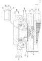
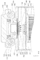
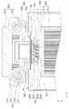
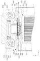
- FIG. 6A to 6C are cross-sectional views showing the elevation of the multi-well plate in the nucleic acid amplification test apparatus of FIG. 1, and FIG. 6A is a cross-sectional view showing a state in which the multi-well plate is inserted into the housing. It is a cross-sectional view showing a state in which the plate is partially lifted to support the reaction tube, and FIG. 6C is a cross-sectional view illustrating a state in which the multi-well plate is lifted and the reaction tube and the sealing film are in contact.
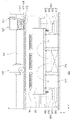
- FIG. 7 is a cross-sectional view showing a state of the temperature control block in the nucleic acid amplification test apparatus of FIG.
- FIG. 8 is a cross-sectional view showing a temperature control block and a lift driving part in the nucleic acid amplification test apparatus of FIG. 1 .
- FIG. 9 is a perspective view showing the state of the sealing plate of the sealing film type of the nucleic acid amplification test apparatus of FIG.
- FIG. 10 is a perspective view showing the state of the sealing plate of the sealing cap type in the nucleic acid amplification test apparatus of FIG.
- FIG. 11 is a perspective view illustrating a multi-well plate in which a plurality of reaction tubes for nucleic acid amplification of the nucleic acid amplification test apparatus of FIG. 1 are mounted.
- the automatic sample analysis system is an automatic sample analysis system that simultaneously performs qualitative or quantitative analysis of a target nucleic acid, and separates and purifies the target nucleic acid at the dispensing position (P).
- an automatic purification dispensing device 10 for dispensing the target nucleic acid to the plurality of reaction tubes 1; and a nucleic acid amplification test device 20 that measures the target nucleic acid in the plurality of reaction tubes 1 received from the automatic purification and dispensing device 10 in real time.
- the sample to be analyzed is a configuration including the target nucleic acid to be tested, and various configurations are possible.
- the sample is a biological sample, and may mean blood, urine, tissue, saliva, sputum, etc. containing the target nucleic acid obtained from a living organism, and further may include the living body itself such as animals, plants, microorganisms, etc. there is.
- the automatic sample analysis system can purify the target nucleic acid to be analyzed from the sample and perform the analysis as detection through amplification of the target nucleic acid.
- the automatic purification and dispensing device 10 is configured to purify and dispense a target nucleic acid for measurement in real time by amplifying it through a nucleic acid amplification testing device 20 to be described later and dispensing it with the nucleic acid amplification testing device 20, as previously disclosed. Applicable to any type of device will be briefly described below.
- the automatic purification dispensing device 10 includes a purification unit for purifying the target nucleic acid from the sample, including a multi-well plate kit (not shown) containing reagents necessary for purification of the sample, and a plurality of pipettes 11 ) may include a pipette block 12 that is detachably mounted to move the sample, reagent, and target nucleic acid.
- a purification unit for purifying the target nucleic acid from the sample including a multi-well plate kit (not shown) containing reagents necessary for purification of the sample, and a plurality of pipettes 11 ) may include a pipette block 12 that is detachably mounted to move the sample, reagent, and target nucleic acid.
- the automatic tablet dispensing device 10 may further include a pipette block driver (not shown) for driving the pipette block 12 so that the pipette block 12 can move in at least one of up, down, left, and right directions. there is.
- a pipette block driver (not shown) for driving the pipette block 12 so that the pipette block 12 can move in at least one of up, down, left, and right directions. there is.
- the purification unit has a plurality of columns, and a multi-well plate kit in which a sample for purifying the target nucleic acid and reagents necessary for purifying the target nucleic acid are built in a specific column, and by applying a magnetic field to a specific column of the multi-well plate kit, It may include a magnetic field applying unit for separating magnetic particles attached to the target nucleic acid, and a heating unit that accelerates purification of the target nucleic acid by applying heat to a specific heat of the multi-well plate kit.
- the pipette block 12 is a configuration in which a plurality of pipettes 11 are detachably mounted to move samples, reagents, and target nucleic acids used in purification, and various configurations are possible.
- a plurality of insertion holes may be formed so that the plurality of pipettes 11 can be inserted and inserted with heat, and samples, reagents, target nucleic acids, etc. can be sucked and discharged.
- the pipette block 12 can transfer the target nucleic acid obtained through the purification unit to the nucleic acid amplification test apparatus 20 through relative movement with the multi-well plate 40 to be described later.
- the pipette block 12 can perform relative movement with the multi-well plate 40, and the detailed relative movement process will be described later.
- the pipette block driving unit drives the pipette block 12 in at least one of up, down, left, and right directions, so that a plurality of pipettes 11 of the pipette block 12 move various samples, reagents, target nucleic acids, etc. It can be sucked and discharged.
- the nucleic acid amplification test apparatus 20 includes a housing 30 forming an inner space S1 and a plurality of the reaction tubes, as shown in FIGS. 3 to 5 .
- (1) may include a multi-well plate insertion unit 100 that supports the multi-well plate 40 provided with and is movably installed between the dispensing position P and the inner space S1.
- the housing 30 has a rectangular parallelepiped shape and forms an inner space S1 isolated from the outer space, and the multi-well plate 40 having a plurality of reaction tubes 1 is inserted therein and taken out.
- the housing 30 is a target nucleic acid through the automatic tablet dispensing device 10 from the inner space S1 through the movement of the multi-well plate inserting part 100 supporting the multi-well plate 40 on one side.
- a shutter 60 may be provided so as to be reciprocally movable between the dispensing positions P for receiving .
- the housing 30 includes an internal space S1 and an internal space S1 in a state where the multi-well plate inserting unit 100 supports the multi-well plate 40 on one side where the automatic tablet dispensing device 10 is located.
- a shutter 60 may be provided to move between the dispensing positions P.
- the shutter 60 includes a door part 61 forming a part of one side of the housing 30 and a door hinge 62 enabling opening and closing through rotation of the door part 61 .
- the shutter 60 is opened by hinge rotation through the door hinge 62 of the door unit 61 when the door unit 61 is pressed according to the movement of the multi-well plate insertion unit 100 while opening the multi-well plate.
- the plate inserting unit 100 is movable.
- the door unit 61 may maintain an open state through partial interference with the multi-well plate insertion unit 100 .
- the multi-well plate insertion unit 100 supports the multi-well plate 40 provided with a plurality of reaction tubes 1 and is movably installed between the dispensing position P and the internal space S1. , various configurations are possible.
- the multi-well plate inserting unit 100 may further include a support driving block 130 provided at both lower ends of the supporting unit 110 to connect the supporting unit 110 and the driving unit 120 to each other.
- the multi-well plate 40 is a configuration in which a plurality of reaction tubes 1 are provided in a plurality of rows, and various configurations are possible.
- the multi-well plate 40 is configured to accommodate a target nucleic acid in order to amplify and detect the target nucleic acid to be analyzed, any conventionally disclosed form is applicable.
- the multi-well plate 40 may have a configuration in which a plurality of reaction tubes 1 are coupled or supported to the plate 41 , and as another example, a plurality of unit wells are formed in the plate 41 . It may be configured to receive the target nucleic acid through the well.
- the support part 110 is a configuration that supports the edge of the multi-well plate 40 provided with a plurality of reaction tubes 1, and various configurations are possible.
- the support 110 has an opening 111 formed in the center to prevent interference with the reaction tube 1 of the multi-well plate 40, and for support of the multi-well plate 40 It may include a step portion 112 .
- the support unit 110 is provided in the inner space S1 to support and move the multi-well plate 40, so that the multi-well plate 40 can be positioned at the amplification position, and furthermore, automatic purification
- the dispensing position P receiving the target nucleic acid from the dispensing device 10 may be moved.
- the opening 111 is a configuration provided so that the plurality of reaction tubes 1 can pass through the support 110 without interfering downward, and may be formed to correspond to the shape of the multi-well plate 40 .
- a plurality of reaction tubes 1 through the opening 111 are positioned at the lower side in a state where the plate 41 is supported by the step 112, and the temperature is controlled through a temperature control block 500 to be described later.
- the support driving block 130 is provided at both lower ends of the support part 110 to connect the support part 110 and the driving part 120, and various configurations are possible.
- the upper side is coupled to the support unit 110 at the lower side of both ends of the support unit 110 , and the lower side is connected to the driving unit 120 , and the supporting unit 110 is moved through the driving force of the driving unit 120 in the inner space ( S1 ). It can be moved from the amplification position to the dispensing position (P).
- the support driving block 130 includes a support plate 131 coupled to the lower side of both ends of the support unit 110 , and a drive belt 121 of the driving unit 120 at the lower side of the support plate 131 . It may include a block portion 132 connected to and a driving guide 133 provided on the support plate 131 .
- the support driving block 130 receives the driving force of the driving unit 120 through the block unit 132 and moves, thereby transmitting the driving force to the supporting unit 110 connected to the supporting plate 131, resulting in With the support 110, it is possible to move between the amplification position and the dispensing position (P).
- the driving guide 133 is a configuration for guiding the movement of the support part 110 , and is provided on the support plate 131 and includes the support plate 131 and the support part together with a guide member provided on the inner wall surface of the housing 30 . It can guide the movement of (110).
- the driving unit 120 is configured to drive the support unit 110 to reciprocate between the housing 30 inner space S1 and the dispensing position P, and various configurations are possible.
- the driving unit 120 is applicable to any method as long as it is a conventionally disclosed driving method, and an electric motor type, a pneumatic driving type, a magnetic field linear motor, etc. may be used.
- the driving unit 120 includes a driving source 122 that rotates by receiving external energy, a pair of pulley parts 123 and 124 connected to the driving source 122 , and a pair of pulley parts 123 . , 124) may include a drive belt 121 connected between.
- the driving source 122 may rotate by receiving external energy, and may rotate at least one of the pair of pulley parts 123 and 124 connected according to the rotational movement.
- At least one of the pair of pulley parts 123 and 124 rotates according to the rotation of the driving source 122 and the other rotates vertically through the connected driving belt 121 to move the driving belt 121.
- the drive belt 121 is connected to the support plate 131 through the block part 132 of the support drive block 130 as described above, and the support plate 131 according to the movement of the drive belt 121 . ) and the support unit 110 can be moved.
- the above-mentioned movement can be moved in various directions such as linear movement and rotational movement such as up, down, left, right, and more specifically, linear and horizontal movement of the side of the housing 30 of the nucleic acid amplification test device 20 .
- the multi-well plate 40 can approach the automatic tablet dispensing device 10 side.
- the nucleic acid amplification test apparatus 20 automatically receives the target nucleic acid obtained from the automatic purification and dispensing apparatus 10, and the sealing of the multi-well plate 40 is automatically performed. can be performed.
- the nucleic acid amplification test apparatus 20 includes, as shown in FIGS. 5 and 6, a housing 30 forming an internal space (S1) isolated from the outside; a multi-well plate inserting unit 100 supporting the multi-well plate 40 provided with a plurality of reaction tubes 1 in which the target nucleic acid received through the automatic tablet dispensing device 10 is accommodated; a sealing plate inserting part 200 for supporting a sealing plate 50 provided with a sealing means for sealing the inlets of the plurality of reaction tubes 1 from an upper side of the multi-well plate 40; an automatic sealing unit 300 for sealing the sealing unit to the inlet of the reaction tube 1 by moving the sealing unit and the multi-well plate 40 to be adjacent to each other; a fluorescence detection unit 400 disposed above the sealing plate insertion unit 200 and configured to detect the target nucleic acid in the reaction tube 1; It is disposed on the lower side of the multi-well plate insertion part 100, and includes a temperature control block 500 for controlling the temperature of the target nucleic acid in the reaction
- the housing 30 is configured to form an internal space S1 isolated from the outside, and an insertion part 33 for inserting the multi-well plate 40 and the sealing plate 50 provided with the sealing means from the outside.
- the housing 30 may include an open insertion part 33 into which the multi-well plate 40 and the sealing plate 50 are inserted into the internal space S1 isolated from the outside.
- the insertion part 33 may be formed to have a size corresponding to the sealing plate 50 and the multi-well plate 40 on one side of the upper surface of the housing 30 to be opened, and the aforementioned support part 110 is positioned to It can be inserted by sliding while supporting the edge of the well plate (40).
- the insertion part 33 may be inserted by sliding while supporting the edge of the sealing plate 50 at which the sealing plate insertion part 200 to be described later is located.
- the multi-well plate inserting unit 100 is a configuration that supports the multi-well plate 40 provided with a plurality of reaction tubes 1 in which the target nucleic acid received through the automatic tablet dispensing device 10 is accommodated, and has various configurations. This is possible.
- the sealing plate inserting part 200 is a configuration that supports the sealing plate 50 provided with a sealing means for sealing the inlets of the plurality of reaction tubes 1 from the upper side of the multi-well plate 40, and has various configurations. This is possible.
- sealing means according to the present invention may be a sealing film 51 or a sealing cap 52 for sealing the inlet of the reaction tube (1).
- the sealing film 51 reacts in order to prevent evaporation of the target nucleic acid in the process of repeatedly heating and cooling the target nucleic acid accommodated in the reaction tube 1 to an appropriate temperature through a temperature control block 500 to be described later.
- a configuration for sealing the inlet of the tube various configurations are possible.
- the sealing film 51 may be formed and positioned to have a size corresponding to the multi-well plate 40 in which a plurality of reaction tubes 1 are arranged in a plurality of rows.
- the sealing cap 52 is, in order to prevent the target nucleic acid from evaporating in the process of repeatedly heating and cooling the target nucleic acid accommodated in the reaction tube 1 to an appropriate temperature through a temperature control block 500 to be described later.
- a configuration for sealing the inlet of the reaction tube various configurations are possible.
- the sealing cap 52 has a size corresponding to a position corresponding to the inlet of each reaction tube 1 of the multi-well plate 40 in which a plurality of reaction tubes 1 are arranged in a plurality of rows. A plurality may be arranged and provided.
- sealing film 51 is described as a main embodiment below, it goes without saying that the configuration of the sealing film 51 can be applied as the sealing cap 52 .
- the sealing plate 50 is a plate provided with a sealing film 51 , and may be positioned at an upper position of the multi-well plate 40 through the insertion part 33 of the housing 30 described above.
- the sealing plate insertion unit 200 is provided on the upper side of the multi-well plate insertion unit 100 in the inner space S1 to support the sealing plate 50 , and various configurations are possible.
- the sealing plate insertion part 200 has an open center so that the plurality of reaction tubes 1 provided in the multi-well plate 40 can contact the lower side of the sealing film 51 , A support step 210 for supporting the edge may be formed.
- the sealing plate insertion part 200 may be formed in a shape corresponding to the shape of the sealing plate 50 , and the end is formed adjacent to the insertion part 33 , so that the sealing plate through the support step 210 . 50 may be slidably inserted and supported.
- the sealing plate insertion unit 200 or the sealing plate 50 may be provided with identification information such as barcodes and QR codes that can be sensed through a measurement sensor 550 to be described later.
- the automatic sealing unit 300 is configured to seal the sealing film 510 to the inlet of the reaction tube 1 by moving the sealing film 51 and the multi-well plate 40 to be adjacent to each other. It is possible.
- the automatic sealing unit 300 is provided movably on the upper side of the sealing plate insertion unit 200 , and a pressing unit that directly or indirectly presses the sealing film 51 toward the multi-well plate 40 . 310 may be included.
- the automatic sealing unit 300 is provided between the pressing unit 310 and the sealing plate 50 seated on the sealing plate insertion unit 200, the reaction of the multi-well plate 40
- a heating unit 320 for creating a high-temperature environment on the inlet side of the tube 1 may be further included.
- the pressing unit 310 is provided movably on the upper side of the sealing plate insertion unit 200 to directly or indirectly press the sealing film 51 toward the multi-well plate 40, and various configurations are possible. Do.
- the pressing unit 310 presses the sealing plate 50 toward the multi-well plate 40 in a state in which the sealing plate 50 and the multi-well plate 40 are arranged to be spaced apart from each other by a predetermined interval to form a sealing film. (51) can be made to seal the inlet of the reaction tubes (1).
- the sealing film 51 is reacted through rolling of horizontal movement. It may include a pressure roller 311 sealing the inlet of the tube 1 and a roller driving unit 900 for driving the pressure roller 311 .
- the pressing unit 310 includes a pressing roller shaft 312 installed across both ends from the center of the pressing roller 311, and a pressing roller body 313 on which the pressing roller shaft 312 is installed.
- a pressing roller shaft 312 installed across both ends from the center of the pressing roller 311, and a pressing roller body 313 on which the pressing roller shaft 312 is installed.
- the pressing part 310 may include an elastic connection part 314 for being elastically connected to the driving body 910 of the roller driving part 900 to be described later.
- the pressing roller body 313 is connected to the roller driving part 900 and the elastic connecting part 314, and the pressing roller shaft 312 and the pressing roller (312) are connected to the pressing roller body 313. 313) is provided to rotate and move the pressure roller 313.
- the roller driving part 900 forms a movement path of the driving body 910 connected to the pressing roller body 313 and the elastic connection part 314 through the elastic connection part 314 and the pressing roller 311, and controls the movement of the driving body 910.
- a driving shaft 920 for guiding, and a pressure drive belt 941 are connected to the drive body 910 and a pressure drive belt part 940 for moving the drive body 910 through rotation of the pressure drive belt 941 and , it may include a pressure drive source 930 for moving the drive body 910 by driving the pressure drive belt unit 940 .
- the pressure driving belt unit 940 is connected to the driving body 910 and the driving body 910 is parallel to the driving shaft 920 with respect to the driving shaft 920 for guiding the movement of the driving body 910 .
- a pressure drive belt 941 connected to the pressure drive belt 941 may include a pair of pressure drive pulleys 942 provided at both ends provided to rotate.
- the rotational motion of the pressure roller drive source 943 which is a motor, is transmitted to the pressure drive pulley 942, and one end of the pressure drive pulley 942 rotates to rotate the pressure drive belt 941 and the pair of pressure drive pulleys 942.
- the driving body 910 connected to the pressure driving belt 941 is guided to the driving shaft 920 to move linearly.
- the roller drive unit 900 is transmitted from the pressure drive source 930 in order to drive the pressure drive belt units 940 provided on both sides with respect to the drive shaft 920 through one pressure drive source 930 . It may further include a drive transmission shaft 950 provided across a pair of drive shafts 920 in order to transmit the rotational force to be applied to each of the pressing drive pulleys 942 .
- the heating unit 320 is provided between the pressing unit 310 and the sealing plate 50 seated on the sealing plate inserting unit 200, and the high temperature at the inlet side of the reaction tube 1 of the multi-well plate 40 As a configuration for creating an environment, various configurations are possible.
- the heating unit 320 is a heater provided between the pressing unit 310 and the sealing plate 50 seated on the sealing plate inserting unit 200, and a high temperature at the inlet side of the reaction tube 1 .
- the heating unit 320 is a heater provided between the pressing unit 310 and the sealing plate 50 seated on the sealing plate inserting unit 200, and a high temperature at the inlet side of the reaction tube 1 .
- the heating unit 320 additionally may serve to strengthen the sealing of the sealing means to the inlet of the reaction tube (1).
- the heating unit 320 prevents condensation or moisture from forming on the inlet side of the reaction tube 1 to block, reflect, and scatter light through the fluorescence detection unit 400 to be described later. It can be prevented so that fluorescence detection can be performed smoothly.
- the heating unit 320 includes a heater 321 for transferring heat to the inlet of the reaction tube 1 , and a heater upper cover 322 and a heater 321 protecting the heater 321 from the upper side.
- a heater lower cover 323 positioned to be supported by the sealing plate inserting part 200 from the lower side.
- the heater 321 is configured to transfer heat to the upper portion of the reaction tube 1 , and may prevent condensation and moisture from occurring on the inlet side of the reaction tube 1 .
- the heater upper cover 322 is provided on the upper side of the heater 321 to protect the heater 321 and the sealing film 51 in the process of pressing the sealing film 51 through the pressing unit 310. , various configurations are possible.
- the heater upper cover 322 is located on the upper side of the heater 321 and transmits the pressing force of the pressing part 310 to the sealing film 51 through the heater 321, so that the sealing film 51 is plural. It can be made to be in close contact with the upper portion of the multi-well plate 40 including the reaction tube (1) of the.
- the heater upper cover 322 prevents direct pressurization through the pressurizing part 310 of the sealing film 51 and indirectly presses the sealing film 51 to prevent damage to the sealing film 51, while maintaining an appropriate pressurizing force.
- the sealing film 51 may be in close contact with and in contact with the upper side of the multi-well plate 40 .
- the heating unit 320 includes a plurality of reaction tubes 1 for detecting a target nucleic acid through the fluorescence detection unit 400 disposed above the sealing plate insertion unit 200 with respect to the reaction tube 1 .
- Through-holes 324 corresponding to may be formed.
- the through hole 324 includes a heater upper cover 322 and a heater 321 in order to detect the target nucleic acid accommodated in the reaction tube 1 through light irradiation through a fluorescence detection unit 400 to be described later. It may be formed in the heating unit 320 to the.
- the through hole 324 is formed by being aligned at the position where the plurality of reaction tubes 1 among the heater upper cover 322 and the heater 321 are located, and thus the heater upper cover 322 and the heater 321 are formed. It is possible to detect the target nucleic acid through the light passing through it.
- the heating unit 320 including the heater upper cover 322 and the heater 321 may have elasticity so that the pressing force through the pressing unit 310 can be transmitted to the sealing film 51 . there is.
- the fluorescence detection unit 400 is disposed above the sealing plate insertion unit 200 to detect the target nucleic acid in the reaction tube 1 , and various configurations are possible.
- the fluorescence detection unit 400 includes a detection unit 430 for irradiating light with which the target nucleic acid reacts toward the reaction tube 1 and sensing the light according to the reaction of the target nucleic acid, and the detection unit 430 is sealed. It may include a detection driving unit 440 for driving so as to be movable from the upper side of the plate inserting unit 200 .
- the fluorescence detection unit 400 irradiates excitation light to which the target nucleic acid accommodated in the reaction tube 1 reacts, and senses the fluorescence according to the fluorescence to measure the target nucleic acid accommodated in the reaction tube 1 in real time. there is.
- the detection unit 430 is configured to irradiate light with which the target nucleic acid reacts toward the reaction tube 1 and sense the fluorescence of the target nucleic acid, and various configurations are possible.
- the detection unit 430 may include a light source unit 410 for irradiating excitation light with which the target nucleic acid reacts toward the reaction tube 1 , and sensing fluorescence generated in proportion to the concentration of the target nucleic acid through the irradiated light. It may include a detection sensor 420 that
- the detection unit 430 senses the light source unit 410 that irradiates excitation light specific to each target nucleic acid toward the reaction tube 1 and each fluorescence generated
- the detection sensor 420 may be provided, and as another example, the light source unit 410 and the detection sensor 420 may be separately provided and configured to detect.
- the light source unit 410 is configured to irradiate light of a specific wavelength to which the target nucleic acid reacts toward the reaction tube 1, and the light in the target wavelength band is variously applied according to the type of fluorescent probe specific to the target nucleic acid to be analyzed. It is possible.
- the light source unit 410 is positioned above the heating unit 320 and irradiates excitation light to reach the reaction tube 1 through the through hole 324 provided in the heating unit 320 . can do.
- the light source unit 410 may be fixedly disposed at a position vertically aligned with the reaction tube 1 and the through hole 324 of the upper end of the housing 30, and as another example, a detection driving unit 440 to be described later. It can be positioned in the correct position by driving it through the
- the detection sensor 420 is configured to sense fluorescence generated through excitation light irradiated from the light source unit 410 to the target nucleic acid in the reaction tube 1 , and various configurations are possible.
- the detection sensor 420 can measure the amount of target nucleic acids in real time by irradiating excitation light of a specific wavelength band to detect fluorescence generated in proportion to the concentration of the target nucleic acid, and, like the light source unit 410 , a through hole ( 324 ), it may be fixedly disposed at a position vertically aligned with it, or it may be moved along with the light source unit 410 through the detection driving unit 440 to be in a fixed position.
- the detection driving unit 440 is configured to drive the detection unit 430 to be movable from the upper side of the sealing plate insertion unit 200 , and various configurations are possible.
- the detection driving unit 440 may be provided to drive independently from the pressing unit 310 through a separate driving source while sharing the driving shaft 920 with the aforementioned roller driving unit 900 .
- the detection driving unit 440 is connected to the driving shaft 920 of the roller driving unit 900 to move in the longitudinal direction of the nucleic acid amplification test apparatus 20 and the sealing plate 50 .
- the detection driving unit 440 may further include a configuration for driving the nucleic acid amplification and testing device 20 and the sealing plate 50 in the vertical and vertical directions with respect to the longitudinal direction.
- the detection driving unit 440 includes a detection driving block 444 including a detection unit 430 , and a pair of detection driving guides 442 and 443 for guiding the movement of the detection driving block 444 , and , a pair of detection drive belts 445 and 446 connected to the detection drive block 444 to move the detection drive block 444, and a pair of detection drive belts 445 and 446 for moving the pair of detection drive belts 445 and 446 It may include driving pulleys 447 and 448 and a detection driving source 441 for driving a pair of detection driving belts 445 and 446, respectively.
- the detection driver 440 will be described in detail with reference to FIG. 4 as follows.
- Two of the detection drive sources 441 are provided at the ends of the drive shaft 910 , respectively, to drive the detection drive belt 445 to rotate.
- the pair of detection drive pulleys 447 and 448 are provided at opposite ends of the detection drive source 441 , respectively, to guide the rotation of the pair of detection drive belts 445 and 446 .
- the pair of detection drive pulleys 447 and 448 are disposed at the ends of the pair of drive shafts 910 , respectively, so that the pair of detection drive belts 445 and 446 move toward the edge of the drive shaft 910 . can be placed.
- one detection drive belt 445 is connected to a corresponding one detection drive source 441 and rotates, and the path is a drive shaft ( It is connected from one side of the drive shaft 910 so as to be parallel to 910 , and at the opposite ends of the detection unit 430 and the drive shaft 910 , a pair of detection drive pulleys 447 and 448 and a pair of drive shafts 910 are disposed on the outer shell. and may be arranged in a rectangular shape on a plane.
- one detection drive belt 445 is connected to one detection drive source 441 and passes through the detection drive pulley 447 positioned at the end along the drive shaft 910 and the other detection drive pulley 448 positioned side by side. In a state arranged across the drive shaft 910 to be connected to the detection drive block 444 by changing the direction using the detection drive pulley 448 again, it may be connected to one detection drive source 441 again.
- the other detection drive belt 446 is symmetrical thereto and is connected to the other detection drive source 441 facing the one detection drive source 441 described above, and the end of the drive shaft 910 along the opposite drive shaft 910 . It reaches another detection drive pulley 447 through the detection drive pulley 448 located at In the disposed state, it may be connected to another detection and driving source 441 again.
- the detection driving unit 440 can freely move the movement of the detection unit 430 in the X and Y directions on the plane of FIG. 4 , and can be driven independently of the above-described pressing unit 310 . .
- the detection driving unit 440 may vertically move the detection unit 430 in the same manner as described above.
- the detection driving unit 440 constitutes an independent driving unit separately from the above-described embodiment of linear movement in the longitudinal direction through the roller driving unit 900 to move the detection unit 430 from the upper side of the housing 30 to the length.
- the detection driving unit 440 constitutes an independent driving unit separately from the above-described embodiment of linear movement in the longitudinal direction through the roller driving unit 900 to move the detection unit 430 from the upper side of the housing 30 to the length.
- the temperature control block 500 is, as shown in FIGS. 7 and 8 , disposed below the multi-well plate inserting part 100 to control the temperature of the target nucleic acid in the reaction tube 1 .
- various configurations are possible.
- the temperature control block 500 is disposed on the lower side of the multi-well plate inserting unit 100, and a heating block 510 for controlling the temperature of the reaction tube 1 by performing heat exchange with the reaction tube 1; It may include a heat dissipation unit 800 provided under the heating block 510 to transfer heat generated in the heating block 510 to the outside.
- the temperature control block 500 moves the heating block 510 supporting the multi-well plate 40 up and down by driving the heat dissipation unit 800 up and down to adjust the position of the multi-well plate 40 . It may further include a lift driving unit 600 that drives up and down.
- the heating block 510 is disposed on the lower side of the multi-well plate inserting unit 100 and controls the temperature of the reaction tube 1 by performing heat exchange with the reaction tube 1, and various configurations are possible. .
- the heating block 510 has a thermoelectric module 520, a bottom surface of which is in surface contact with the thermoelectric module 520, and a plurality of insertion grooves 531 for inserting the plurality of reaction tubes 1 on the top surface. It may include a reaction block 530 in which they are formed.
- the heating block 510 may further include a reaction cover 540 coupled to the reaction block 530 to surround the outer surface of the reaction block 530 .
- the heating block 510 may include a measurement sensor 550 for identifying the presence or absence of the sealing plate 50 by sensing the sealing plate 50 disposed on the upper side.
- the heating block 510 is disposed on the lower side of the multi-well plate inserting unit 100, and by performing heat exchange with the reaction tube 1, the temperature of the reaction tube 1 is controlled by the target in the reaction tube 1 .
- a configuration for amplifying a nucleic acid various configurations are possible.
- the heating block 510 may induce amplification of the target nucleic acid by repeatedly performing a combination of heating and cooling as a unit cycle, and in this case, the specific contents of temperature control may be variously applied according to the type of target nucleic acid.
- thermoelectric module 520 is a configuration that adjusts temperature, heating, and cooling according to the application of current and the direction thereof, and various configurations are possible.
- thermoelectric module 520 is applicable to any conventionally disclosed thermoelectric module 520 , and supports the reaction tubes 1 under the multi-well plate 40 provided with the reaction tubes 1 . It may be provided to correspond to the bottom surface of the reaction block 530 .
- the reaction block 530 is a configuration in which a bottom surface is in surface contact with the thermoelectric module 520 and a plurality of insertion grooves 531 for inserting a plurality of reaction tubes 1 are formed on the top surface, and various configurations are possible. .
- the reaction block 530 is disposed on the upper side of the thermoelectric module 520 and at least a part of the reaction tube 1 at a position corresponding to the reaction tubes 1, more preferably, the target nucleic acid to be accommodated is completely inserted. Insertion grooves 531 may be provided.
- reaction block 530 allows the lower part of the reaction tube 1 to be inserted into the insertion groove 531 so that the heat through the thermoelectric module 520 is transferred to the reaction tube 1, in particular the target nucleic acid is located.
- the position of the reaction tube 1 and heat exchange may be performed.
- reaction block 530 raises the reaction tubes 1 by supporting the reaction tubes 1 when ascending through the elevating driving unit 600 to be described later, so that the inlet of the reaction tube 1 is sealed with a sealing film. It can be made to reach a position adjacent to (51).
- the reaction cover 540 is a configuration coupled to the reaction block 530 so as to surround the outer surface of the reaction block 530, various configurations are possible.
- reaction cover 540 is coupled to the edge of the reaction block 530 and the heat transferred through the thermoelectric module 520 is transferred to the reaction block 530 without dissipating to the side of the reaction block 530 to increase thermal efficiency. can be made to increase.
- reaction cover 540 may be raised by supporting the plate 41 of the multi-well plate 40 when the reaction cover 540 is raised through the lift driving unit 600 to be described later.
- the measurement sensor 550 is a configuration that identifies the presence or absence of the sealing plate 50 by sensing the sealing plate 50 disposed on the upper side, and various configurations are possible.
- the measurement sensor 550 is provided on the outside of the reaction cover 540 and irradiates light toward the upper sealing plate 50 or the sealing plate inserting unit 200, thereby sensing the reflected light.
- the presence or absence of the sealing film 51 can be identified.
- the measurement sensor 550 is provided on the outside of the reaction cover 540 and has identification information such as barcodes and QR codes that can be sensed in the upper sealing plate 50 or sealing plate insertion unit 200 .
- identification information such as barcodes and QR codes that can be sensed in the upper sealing plate 50 or sealing plate insertion unit 200 .
- the presence or absence and related information can be identified by recognizing the degree of identification.
- the heat dissipation unit 800 is provided on the lower side of the heating block 510 to transfer heat generated from the heating block 510 to the outside, and various configurations are possible.
- the heat dissipation unit 800 is a heat dissipation plate including a heat dissipation plate 811 provided in surface contact from the lower side of the heating block 510 and a plurality of heat dissipation fins 812 provided in the heat dissipation plate 811 . (810) and; A plurality of heat dissipation fins 812 are coupled to the heat dissipation plate 811 so as to be located in the separation space S2 separated from the inner space S1 to form a separation space S2 together with the heat dissipation plate 811.
- a plurality of side portions 820 and a lower surface portion 830 may be included.
- the heat dissipation unit 800 is provided to independently communicate with the separation space S2 and the outside of the housing 30 , and an air circulation unit that circulates the inside air of the separation space S2 with the outside air of the housing 30 . (840) may be further included.
- the heat sink 810 is provided on the lower side of the heating block 510 in contact with the thermoelectric module 520 to transfer heat generated from the heating block 510 to the outside, and various configurations are possible.
- the heat dissipation plate 810 may include a heat dissipation plate 811 provided in surface contact from the lower side of the heating block 510 and a plurality of heat dissipation fins 812 provided in the heat dissipation plate 811 . there is.
- the heat dissipation plate 810 is configured to be disposed under the thermoelectric module 520 such that the plurality of heat dissipation fins 812 are positioned downward, and any conventionally disclosed heat dissipation plate 810 is applicable.
- the heat dissipation plate 811 has a refrigerant path 813 formed therein to continuously heat exchange through the refrigerant, thereby maximizing heat dissipation efficiency.
- the refrigerant path 813 and the refrigerant may be various types of refrigerants disclosed in the prior art.
- heat dissipation fins 812 are provided on the heat dissipation plate 811 in plurality to increase heat dissipation efficiency, and various configurations are possible.
- the heat dissipation fins 812 may be provided in the form of simple fins, but more preferably may be parallel planar fins having an area.
- the heat dissipation fins 812 may be disposed parallel to the air flow direction for smooth air circulation of the air circulation unit 840 to be described later.
- the side portion 820 and the lower surface portion 830 are coupled to the heat dissipation plate 811 such that the plurality of heat dissipation fins 812 are located in the separation space S2 separated from the inner space S1 to dissipate the heat dissipation plate 811.
- the separation space (S2) As a configuration for forming the separation space (S2) together with, various configurations are possible.
- the side portion 820 and the lower surface portion 830 have a plurality of heat dissipation fins 812 therein located in a separate separation space S2 separated from the interior space S1, the heat dissipation plate 811 of The side part 820 may be coupled to the lower edge, and the lower surface part 830 may be coupled to the lower side of the plurality of side parts 820 .
- the separation space S2 in which the heat dissipation fin 812 is located may be formed to enable air circulation through the air circulation unit 840 .
- the air circulation unit 840 is provided to independently communicate with the separation space S2 and the outside of the housing 30 , and circulates the bet air of the separation space S2 with the outside air of the housing 30 . configuration is possible.
- the air circulation unit 840 is installed in at least one of a plurality of connection pipes 841 connected between the lower surface portion 830 and the housing 30 and a plurality of connection pipes 841 . It may include an air circulation fan 842 for sucking air outside the housing 30 or discharging the air inside the separation space S2.
- the air circulation unit 840 is in direct communication with the separation space S2 formed through the side portions 820 and the lower surface portion 830 described above and the outside of the housing 30 to continuously in the separation space S2.
- the air circulation unit 840 is in direct communication with the separation space S2 formed through the side portions 820 and the lower surface portion 830 described above and the outside of the housing 30 to continuously in the separation space S2.
- the air circulation unit 840 has a plurality of connecting pipes 841 connected between the lower surface portion 830 and the housing 30 are connected to each other, and is separated from the inner space S1 and is a housing independently. (30) It can be made to communicate with the outside and the separation space (S2).
- connection pipes 841 are, in order to maintain a separation state between the separation space S2 and the internal space S1 when the entire heat dissipation unit 800 is driven upward and downward through the lifting driving unit 600 to be described later. It may be provided as a corrugated pipe or a bellows.
- the connecting pipes 841 are more preferably provided in three pieces to be connected between the lower surface portion 830 and the housing 30 .
- the air circulation fan 842 may be installed in at least one of the plurality of connection pipes 841 to suck in air outside the housing 30 or to exhaust air inside the separation space S2 .
- the air circulation fan 842 is installed in one of the plurality of connection pipes 841 and sucks air from the outside of the housing 30, so that the air circulation fan 842 is installed on another connection pipe where the air circulation fan 842 is not installed.
- the air in the separation space S2 may be discharged to the outside of the housing 30 through the 841 .
- the air circulation fan 842 is installed in one of the plurality of connection pipes 841 to discharge air outside the housing 30, so that the air circulation fan 842 is not installed in another connection pipe 841 ). It is possible to introduce air from the outside of the housing 30 into the separation space S2 through the .
- the lifting driving unit 600 by driving the heat dissipation unit 800 up and down, the heating block 510 supporting the multi-well plate 40 is moved up and down, As a configuration for driving the position of the multi-well plate 40 up and down, various configurations are possible.
- the elevating driving unit 600 simply heats the reaction tubes 1 of the multi-well plate 40 supported by the multi-well plate inserting unit 100 through elevating the heat dissipating unit 800 through the heating block 510. can be supported through
- the elevating driving unit 600 elevates the multi-well plate 40 supported by the multi-well plate insertion unit 100 through the elevating of the heat dissipating unit 800 through the heating block 510 to raise the sealing film ( 51), it can be supported by raising it to a position adjacent to it.
- the lifting driving unit 600 supports the lower side of the reaction tube 1 in the pressurization process of the above-described pressurizing unit 310 , thereby improving the degree of completeness of the sealing.
- the elevating driving unit 600 may attach the plurality of reaction tubes 1 to the sealing film 51 by moving the multi-well plate 40 by elevating and driving the heat dissipating unit 800 . there is.
- the lift driving unit 600 elevates the multi-well plate 40 to the sealing film plate 50 through the elevation of the heat dissipation unit 800, so that the inlet of the reaction tube 1 is sealed.
- the sealing film 51 may be sealed to the reaction tube 1 .
- the elevating driving unit 600 is a configuration for elevating and driving the heat dissipation unit 800 , and various conventionally disclosed elevating driving methods may be applied.
- the lift driving unit 600 may be lifted and driven through various methods such as a pulley method using an electric motor, a ball screw linear movement method, a hydraulic drive method, and a linear drive method using an electromagnetic field.
- the lifting drive unit 600 is connected to a rotary drive source 610 that rotates through external energy, a lift rotary shaft 620 that rotates by being connected through a rotary drive source 610, and a lift rotary shaft 620. It may include a lift drive connection block 630 that is used, a lift drive connection block 630 and a heat dissipation unit 800 , and more specifically, a lift guide 640 connected to the lower surface portion 830 .
- the elevating drive unit 600 rotates the elevating rotary shaft 620 through the rotary drive source 610, thereby moving the elevating rotary shaft 620 and the screwed elevating drive connecting block 630 up and down to move,
- the unit 830 may be lifted and driven along the elevating guide 640 .
- the scan unit 700 scans the identification information code attached to the reaction tube 1 to acquire target nucleic acid information, and various configurations are possible.
- the scanning unit 700 is provided together with the above-described fluorescence detection unit 400 or is separately provided on the upper side of the housing 30 to scan the identification information code attached to the reaction tube 1, It is possible to obtain and identify information on the target nucleic acid.
- the scanning unit 700 may scan the location information code attached to the sealing plate 50 to further identify the presence or absence of the sealing film 51 .
- the sealing means according to the present invention in particular, the sealing cap 52 may be provided, for example, corresponding to the number of reaction tubes 1 , and more specifically, eight reaction tubes. Eight sealing caps 52 are provided corresponding to (1), and handles for carrying the sealing caps 52 by the user at both ends may be provided.
- sealing caps 52 may be provided in a line, and handles may be extended to sealing caps 52 at both ends.
Landscapes
- Chemical & Material Sciences (AREA)
- Health & Medical Sciences (AREA)
- Chemical Kinetics & Catalysis (AREA)
- Life Sciences & Earth Sciences (AREA)
- Clinical Laboratory Science (AREA)
- General Health & Medical Sciences (AREA)
- Biochemistry (AREA)
- Analytical Chemistry (AREA)
- Molecular Biology (AREA)
- Organic Chemistry (AREA)
- Immunology (AREA)
- Physics & Mathematics (AREA)
- Proteomics, Peptides & Aminoacids (AREA)
- Engineering & Computer Science (AREA)
- Wood Science & Technology (AREA)
- Zoology (AREA)
- General Physics & Mathematics (AREA)
- Pathology (AREA)
- Microbiology (AREA)
- General Engineering & Computer Science (AREA)
- Bioinformatics & Cheminformatics (AREA)
- Genetics & Genomics (AREA)
- Biotechnology (AREA)
- Biophysics (AREA)
- Apparatus Associated With Microorganisms And Enzymes (AREA)
- Measuring Or Testing Involving Enzymes Or Micro-Organisms (AREA)
Abstract
Description
Claims (26)
- 분석대상인 타겟핵산을 정제 및 분주하는 자동정제분주장치(10)와, 상기 자동정제분주장치(10)로부터 수득한 상기 타겟핵산을 증폭하여 측정하는 핵산증폭검사장치(20)를 포함하는 시료자동분석시스템의 핵산증폭검사장치로서,외부와 격리된 내부공간(S1)을 형성하는 하우징(30)과;상기 자동정제분주장치(10)를 통해 타겟핵산용액이 수용되는 복수의 반응튜브(1)들이 구비되는 멀티웰플레이트(40)가 삽입되는 멀티웰플레이트삽입부(100)와;복수의 상기 반응튜브(1)들의 입구를 실링하기 위한 실링수단이 구비된 실링플레이트(50)가 삽입되는 실링플레이트삽입부(200)와;상기 실링플레이트삽입부(200)의 상측에 배치되어, 상기 반응튜브(1) 내 상기 타겟핵산을 검출하는 형광검출부(400)와;상기 멀티웰플레이트삽입부(100)의 하측에 배치되어, 상기 반응튜브(1)의 온도를 제어하는 온도제어블록(500)을 포함하며,상기 반응튜브(1)들은,상기 실링수단과 서로 인접하도록 상대이동되어 상기 실링수단으로 실링되는 것을 특징으로 하는 핵산증폭검사장치.
- 청구항 1에 있어서,상기 온도제어블록(500)은,승강구동을 통해 상기 반응튜브(1)를 상기 실링수단에 밀착하도록 상승시킴으로써, 상기 반응튜브(1)들을 상기 실링수단으로 실링하는 것을 하는 것을 특징으로 하는 핵산증폭검사장치.
- 청구항 1에 있어서,상기 온도제어블록(500)은,열전모듈(520)을 포함하여 상기 멀티웰플레이트삽입부(100)의 하측에 배치되어, 상기 반응튜브(1)와 열교환을 수행함으로써 상기 반응튜브(1)의 온도를 제어하는 히팅블록(510)과;상기 히팅블록(510) 하측에 구비되어 상기 열전모듈(520)에서 발생되는 열을 외부로 방출하는 방열부(800)와;상기 방열부(800)를 상하로 구동함으로써, 상기 멀티웰플레이트(40)를 지지하는 상기 히팅블록(510)을 상하로 이동시켜 상기 멀티웰플레이트(40)의 위치를 상하로 구동하는 승강구동부(600)를 포함하는 것을 특징으로 하는 핵산증폭검사장치.
- 청구항 3에 있어서,상기 히팅블록(510)은,상기 열전모듈(520)과, 저면이 상기 열전모듈(520)과 면접촉하고 상면에 복수의 상기 반응튜브(1)들이 삽입되기 위한 복수의 삽입홈(531)들이 형성되는 반응블록(530)을 포함하는 것을 특징으로 하는 핵산증폭검사장치.
- 청구항 3에 있어서,상기 히팅블록(510)은,상기 반응블록(530)의 외측면을 둘러싸도록 상기 반응블록(530)에 결합되는 반응커버(540)를 추가로 포함하는 것을 특징으로 하는 핵산증폭검사장치.
- 청구항 3에 있어서,상기 히팅블록(510)은,상측에 배치되는 상기 실링플레이트(50)를 센싱함으로써, 상기 실링플레이트(50)의 존재유무를 식별하는 측정센서(550)를 포함하는 것을 특징으로 하는 핵산증폭검사장치.
- 청구항 3에 있어서,상기 방열부(800)는,상기 열전모듈(520)의 하측에서 면접촉하여 구비되는 방열플레이트(811)와, 상기 방열플레이트(811)에 구비되는 복수의 방열핀(812)들을 포함하는 방열판(810)과;복수의 상기 방열핀(812)들이 상기 내부공간(S1)과는 분리되는 분리공간(S2)에 위치하도록 상기 방열플레이트(811)에 결합하여 상기 방열플레이트(811)와 함께 상기 분리공간(S2)을 형성하는 복수의 측면부(820)들 및 하면부(830)를 포함하는 것을 특징으로 하는 핵산증폭검사장치.
- 청구항 7에 있어서,상기 방열부(800)는,상기 분리공간(S2)과 상기 하우징(30)의 외부와 독립적으로 연통하도록 구비되어, 상기 분리공간(S2)의 내기를 상기 하우징(30)의 외기와 순환시키는 공기순환부(840)를 포함하는 것을 특징으로 하는 핵산증폭검사장치.
- 청구항 8에 있어서,상기 공기순환부(840)는,상기 하면부(830)와 상기 하우징(30) 사이에 연결되는 복수의 연결배관(841)들과,상기 복수의 연결배관(841)들 중 적어도 하나에 설치되어 상기 하우징(30) 외부의 공기를 흡입하거나 상기 분리공간(S2) 내부의 공기를 배출하는 공기순환팬(842)을 포함하는 것을 특징으로 하는 핵산증폭검사장치.
- 청구항 3에 있어서,상기 승강구동부(600)는,상기 방열부(800)를 승강구동하여 상기 멀티웰플레이트(40)를 이동시킴으로써, 복수의 상기 반응튜브(1)들을 상기 실링수단에 부착하는 것을 특징으로 하는 핵산증폭검사장치.
- 청구항 1에 있어서,상기 멀티웰플레이트삽입부(100)는,복수의 상기 반응튜브(1)들이 구비되는 상기 멀티웰플레이트(40)의 가장자리를 지지하는 지지부(110)와, 상기 지지부(110)를 상기 자동정제분주장치(10)의 분주위치(P)와 상기 하우징(30) 내의 증폭위치 사이에서 구동하는 구동부(120)를 포함하는 것을 특징으로 하는 핵산증폭검사장치.
- 청구항 1에 있어서,상기 하우징(30)은,상기 멀티웰플레이트삽입부(100)의 반입반출을 위한 셔터(60)가 구비되는 것을 특징으로 하는 핵산증폭검사장치.
- 청구항 1에 있어서,상기 실링수단은,상기 반응튜브(1)의 입구를 실링하는 실링필름(51) 또는 실링캡(52)인 것을 특징으로 하는 핵산증폭검사장치.
- 청구항 1에 있어서,상기 실링수단을 상기 멀티웰플레이트(40) 측으로 가압하여 상기 실링수단을 상기 반응튜브(1)의 입구에 실링하는 자동실링부(300)를 포함하며,상기 자동실링부(300)는,상기 실링플레이트삽입부(200)의 상측에서 이동가능하게 구비되어, 상기 실링수단을 상기 멀티웰플레이트(40) 측으로 직접 또는 간접으로 가압하는 가압부(310)를 포함하는 것을 특징으로 하는 핵산증폭검사장치.
- 청구항 14에 있어서,상기 온도제어블록(500)은,복수의 상기 반응튜브(1)들과 상기 실링수단이 서로 밀착하도록, 상기 반응튜브(1)들을 승강구동하여 지지하는 것을 특징으로 하는 핵산증폭검사장치.
- 청구항 14에 있어서,상기 가압부(310)는,상기 실링플레이트삽입부(200)의 상측에서 상기 실링수단을 직접 또는 간접으로 가압한 상태에서, 수평이동의 롤링을 통해 상기 실링수단을 상기 반응튜브(1)의 입구에 실링하는 가압롤러(311)와, 상기 가압롤러(311)를 구동하는 롤러구동부(900)를 포함하는 것을 특징으로 하는 핵산증폭검사장치.
- 청구항 14에 있어서,상기 자동실링부(300)는,상기 가압부(310)와 상기 실링플레이트삽입부(200)에 안착된 상기 실링플레이트(50) 사이에 구비되어, 상기 멀티웰플레이트(40)의 상기 반응튜브(1) 입구 측에 고온환경을 조성하는 가열부(320)를 추가로 포함하는 것을 특징으로 하는 핵산증폭검사장치.
- 청구항 17에 있어서,상기 가열부(320)는,상기 가압부(310)를 통한 가압력이 상기 실링수단으로 전달될 수 있도록 탄성을 가지는 것을 특징으로 하는 핵산증폭검사장치.
- 청구항 17에 있어서,상기 가열부(320)는,상기 반응튜브(1)에 대하여 상기 실링플레이트삽입부(200)의 상측에 배치되는 상기 형광검출부(400)를 통한 상기 타겟핵산 검출을 위하여, 복수의 상기 반응튜브(1)들에 대응되는 관통구(321)들이 형성되는 것을 특징으로 하는 핵산증폭검사장치.
- 청구항 1에 있어서,상기 형광검출부(400)는,상기 반응튜브(1)를 향해 상기 타겟핵산이 반응하는 여기광을 조사하고 상기 타겟핵산의 반응에 따른 형광을 센싱하는 검출부(430)와, 상기 검출부(430)가 상기 실링플레이트삽입부(200)의 상측에서 이동가능하도록 구동하는 검출구동부(440)를 포함하는 것을 특징으로 하는 핵산증폭검사장치.
- 청구항 20에 있어서,상기 검출부(430)는,상기 반응튜브(1)를 향해 상기 타겟핵산이 반응하는 여기광을 조사하는 광원부(410)와, 조사된 상기 여기광을 통한 상기 타겟핵산의 반응에 따른 형광을 센싱하는 검출센서(420)를 포함하는 것을 특징으로 하는 핵산증폭검사장치.
- 청구항 1에 있어서,상기 반응튜브(1)에 부착되는 식별정보코드를 스캔하여, 상기 타겟핵산 정보를 취득하는 스캔부(700)를 추가로 포함하는 것을 특징으로 하는 핵산증폭검사장치.
- 청구항 22에 있어서,상기 스캔부(700)는,상기 실링플레이트(50)에 부착되는 위치정보코드를 스캔하여, 상기 실링수단의 존재유무를 식별하는 것을 특징으로 하는 핵산증폭검사장치.
- 상기 타겟핵산을 분리 및 정제하여 분주위치(P)에서 복수의 반응튜브(1)들에 상기 타겟핵산을 분주하는 자동정제분주장치(10)와;상기 자동정제분주장치(10)로부터 전달받아 복수의 상기 반응튜브(1)들 내에 수용된 타겟핵산용액을 실시간으로 측정하는 핵산증폭검사장치(20)를 포함하며,상기 핵산증폭검사장치(20)는,내부공간(S1)을 형성하는 하우징(30)과, 복수의 상기 반응튜브(1)들이 구비되는 멀티웰플레이트(40)를 지지하며 상기 분주위치(P)와 상기 내부공간(S1) 사이에서 이동가능하게 설치되는 멀티웰플레이트삽입부(100)를 포함하는 것을 특징으로 하는 시료자동분석시스템.
- 청구항 24에 있어서,상기 멀티웰플레이트삽입부(100)는,복수의 상기 반응튜브(1)들이 구비되는 상기 멀티웰플레이트(40)의 가장자리를 지지하는 지지부(110)와, 상기 지지부(110)를 상기 자동정제분주장치(10)의 분주위치(P)와 상기 하우징(30) 내의 상기 타겟핵산의 증폭이 수행되는 증폭위치 사이에서 구동하는 구동부(120)를 포함하는 것을 특징으로 하는 시료자동분석시스템.
- 청구항 24에 있어서,상기 하우징(30)은,상기 멀티웰플레이트삽입부(100)의 반입반출을 위한 셔터(60)가 구비되는 것을 특징으로 하는 시료자동분석시스템.
Priority Applications (5)
| Application Number | Priority Date | Filing Date | Title |
|---|---|---|---|
| CN202180067609.9A CN116234636A (zh) | 2020-10-05 | 2021-10-05 | 核酸扩增检测装置及具有该装置的样品自动分析系统 |
| CA3194559A CA3194559C (en) | 2020-10-05 | 2021-10-05 | Nucleic acid amplification test apparatus, and automatic sample analysis system having same |
| JP2023520380A JP7531057B2 (ja) | 2020-10-05 | 2021-10-05 | 核酸増幅検査装置及びそれを備える試料自動分析システム |
| EP21877928.8A EP4227004A4 (en) | 2020-10-05 | 2021-10-05 | NUCLEIC ACID AMPLIFICATION TEST APPARATUS, AND AUTOMATIC SAMPLE ANALYSIS SYSTEM COMPRISING SAME |
| US18/247,614 US20230372945A1 (en) | 2020-10-05 | 2021-10-05 | Nucleic acid amplification test apparatus, and automatic sample analysis system having same |
Applications Claiming Priority (2)
| Application Number | Priority Date | Filing Date | Title |
|---|---|---|---|
| KR1020200128151A KR102578721B1 (ko) | 2020-10-05 | 2020-10-05 | 핵산증폭검사장치 및 이를 구비하는 시료자동분석시스템 |
| KR10-2020-0128151 | 2020-10-05 |
Publications (1)
| Publication Number | Publication Date |
|---|---|
| WO2022075676A1 true WO2022075676A1 (ko) | 2022-04-14 |
Family
ID=81125876
Family Applications (1)
| Application Number | Title | Priority Date | Filing Date |
|---|---|---|---|
| PCT/KR2021/013552 Ceased WO2022075676A1 (ko) | 2020-10-05 | 2021-10-05 | 핵산증폭검사장치 및 이를 구비하는 시료자동분석시스템 |
Country Status (6)
| Country | Link |
|---|---|
| US (1) | US20230372945A1 (ko) |
| EP (1) | EP4227004A4 (ko) |
| JP (1) | JP7531057B2 (ko) |
| KR (1) | KR102578721B1 (ko) |
| CN (1) | CN116234636A (ko) |
| WO (1) | WO2022075676A1 (ko) |
Families Citing this family (6)
| Publication number | Priority date | Publication date | Assignee | Title |
|---|---|---|---|---|
| WO2024162515A2 (ko) * | 2023-02-01 | 2024-08-08 | 구상호 | 온도 조절 모듈의 인출입이 가능하고 가열 및 냉각 기능을 갖는 핵산 추출 장치 |
| WO2024177178A1 (ko) * | 2023-02-24 | 2024-08-29 | 구상호 | 자성체가 마련된 분리형 슬라이드를 갖는 자성 입자 분리 스탠드 |
| KR102609761B1 (ko) | 2023-05-26 | 2023-12-05 | (주)진스랩 | 시약 플레이트 간이 생산 설비 |
| KR20250020773A (ko) | 2023-08-04 | 2025-02-11 | 이양원 | 정밀 분자진단 자동화 시스템 |
| CN118460361A (zh) * | 2023-09-25 | 2024-08-09 | 艾普拜生物科技(苏州)有限公司 | 用于pcr仪的试样装载单元 |
| CN119040114A (zh) * | 2024-10-31 | 2024-11-29 | 苏州百源基因技术有限公司 | 一种基于样品多通道检测装置的荧光定量pcr仪 |
Citations (5)
| Publication number | Priority date | Publication date | Assignee | Title |
|---|---|---|---|---|
| KR20120044197A (ko) * | 2010-10-27 | 2012-05-07 | (주)바이오니아 | 다양한 생체시료분석을 위한 전자동실시간정량증폭장비, 다양한 생체시료분석을 위한 자동정제 및 반응준비 장치, 전자동 핵산정제 및 실시간 정량 유전자증폭 방법, 전자동 핵산정제방법, 실시간정량pcr을 이용한 병원균의 전자동 생균수검사방법, 정량면역pcr을 이용한 전자동 항원농도획득방법 및 타겟항원에 라벨링된 부착용 타겟핵산의 정제방법 |
| KR20160123356A (ko) * | 2014-02-18 | 2016-10-25 | 라이프 테크놀로지스 코포레이션 | 스케일러블 유전자증폭기를 제공하고 열전 장치를 격리시키기 위한 장치, 시스템 및 방법 |
| JP2016192965A (ja) * | 2010-12-17 | 2016-11-17 | ビージェイエス アイピー リミテッド | 高速pcr加熱のための方法及びシステム |
| KR20190001745A (ko) * | 2017-06-28 | 2019-01-07 | 주식회사 파나진 | 시료 시약 반응 분석용 키트, 이를 이용한 표적 핵산 검출 장치 및 방법 |
| KR20190095080A (ko) * | 2018-02-05 | 2019-08-14 | 주식회사 진시스템 | 단일시료를 이용하여 다중진단이 가능한 실시간 pcr 장치 |
Family Cites Families (11)
| Publication number | Priority date | Publication date | Assignee | Title |
|---|---|---|---|---|
| EP1045038A1 (en) * | 1999-04-08 | 2000-10-18 | Hans-Knöll-Institut Für Naturstoff-Forschung E.V. | Rapid heat block thermocycler |
| US8232091B2 (en) * | 2006-05-17 | 2012-07-31 | California Institute Of Technology | Thermal cycling system |
| EP2646542B1 (en) * | 2010-12-03 | 2023-10-18 | BioFire Defense, LLC | Thermal cycler apparatus |
| KR101917402B1 (ko) | 2011-02-04 | 2019-01-24 | 유니바사루 바이오 리사치 가부시키가이샤 | 자동 반응ㆍ광측정 장치 및 그 방법 |
| JP6072913B2 (ja) * | 2013-07-08 | 2017-02-01 | 株式会社日立ハイテクノロジーズ | 核酸増幅検出装置及びそれを用いた核酸検査装置 |
| CN203754725U (zh) * | 2013-11-13 | 2014-08-06 | 戴小波 | 全自动荧光定量基因扩增仪 |
| CN204589191U (zh) * | 2014-09-25 | 2015-08-26 | 江南大学 | 实时荧光定量恒温核酸扩增仪 |
| DE102015100637B4 (de) * | 2015-01-16 | 2017-02-23 | Analytik Jena Ag | Vorrichtung zum automatischen Durchführen chemischer und biologischer Verfahren in Gefäßplatten |
| KR101813870B1 (ko) * | 2016-04-08 | 2018-01-03 | 주식회사 수젠텍 | 분자진단 자동분석장치 |
| US20210370299A1 (en) * | 2016-09-23 | 2021-12-02 | Archerdx, Llc | Thermal assemblies for nucleic acid preparation |
| JP2018191608A (ja) * | 2017-05-19 | 2018-12-06 | パナソニックIpマネジメント株式会社 | 核酸増幅装置及び核酸増幅方法 |
-
2020
- 2020-10-05 KR KR1020200128151A patent/KR102578721B1/ko active Active
-
2021
- 2021-10-05 JP JP2023520380A patent/JP7531057B2/ja active Active
- 2021-10-05 WO PCT/KR2021/013552 patent/WO2022075676A1/ko not_active Ceased
- 2021-10-05 CN CN202180067609.9A patent/CN116234636A/zh active Pending
- 2021-10-05 US US18/247,614 patent/US20230372945A1/en active Pending
- 2021-10-05 EP EP21877928.8A patent/EP4227004A4/en active Pending
Patent Citations (5)
| Publication number | Priority date | Publication date | Assignee | Title |
|---|---|---|---|---|
| KR20120044197A (ko) * | 2010-10-27 | 2012-05-07 | (주)바이오니아 | 다양한 생체시료분석을 위한 전자동실시간정량증폭장비, 다양한 생체시료분석을 위한 자동정제 및 반응준비 장치, 전자동 핵산정제 및 실시간 정량 유전자증폭 방법, 전자동 핵산정제방법, 실시간정량pcr을 이용한 병원균의 전자동 생균수검사방법, 정량면역pcr을 이용한 전자동 항원농도획득방법 및 타겟항원에 라벨링된 부착용 타겟핵산의 정제방법 |
| JP2016192965A (ja) * | 2010-12-17 | 2016-11-17 | ビージェイエス アイピー リミテッド | 高速pcr加熱のための方法及びシステム |
| KR20160123356A (ko) * | 2014-02-18 | 2016-10-25 | 라이프 테크놀로지스 코포레이션 | 스케일러블 유전자증폭기를 제공하고 열전 장치를 격리시키기 위한 장치, 시스템 및 방법 |
| KR20190001745A (ko) * | 2017-06-28 | 2019-01-07 | 주식회사 파나진 | 시료 시약 반응 분석용 키트, 이를 이용한 표적 핵산 검출 장치 및 방법 |
| KR20190095080A (ko) * | 2018-02-05 | 2019-08-14 | 주식회사 진시스템 | 단일시료를 이용하여 다중진단이 가능한 실시간 pcr 장치 |
Non-Patent Citations (1)
| Title |
|---|
| See also references of EP4227004A4 * |
Also Published As
| Publication number | Publication date |
|---|---|
| EP4227004A4 (en) | 2024-11-13 |
| JP7531057B2 (ja) | 2024-08-08 |
| EP4227004A1 (en) | 2023-08-16 |
| JP2023544397A (ja) | 2023-10-23 |
| US20230372945A1 (en) | 2023-11-23 |
| CN116234636A (zh) | 2023-06-06 |
| CA3194559A1 (en) | 2022-04-14 |
| KR20220045590A (ko) | 2022-04-13 |
| KR102578721B1 (ko) | 2023-09-15 |
Similar Documents
| Publication | Publication Date | Title |
|---|---|---|
| WO2013119049A1 (ko) | 생물학적 시료의 자동 분석 장치 및 방법 | |
| WO2018143680A1 (ko) | 자동화된 액상 면역반응 분석 장치 | |
| WO2020209638A1 (ko) | 중합효소 연쇄반응 시스템 | |
| WO2016182382A1 (ko) | 일체화된 반응 및 검출 수단을 구비한 시험 장치에 사용되는 스테이션 | |
| WO2018139788A1 (ko) | 고속 핵산증폭 장치 및 핵산증폭 반응의 온도조절 방법 | |
| WO2023018194A1 (ko) | Pcr 장치 | |
| WO2022270984A1 (ko) | 개별적으로 동작되는 생물학적 장치들을 이용한 자동화 분석 시스템, 분석 방법 및 저장 매체 | |
| WO2016117726A1 (en) | Cartridge | |
| JP7531057B2 (ja) | 核酸増幅検査装置及びそれを備える試料自動分析システム | |
| WO2019117584A1 (ko) | 중합효소 연쇄반응 시스템 | |
| CN1920585A (zh) | 基板检查装置及基板检查方法 | |
| WO2016088992A1 (en) | Test apparatus and control method thereof | |
| WO2018110953A1 (en) | Substrate processing apparatus and method using the same | |
| EP2633328A2 (en) | Automatic real-time pcr system for the various analysis of biological smaple | |
| WO2020027470A1 (ko) | 자동화된 액상 면역반응 분석 장치 및 그 방법 | |
| WO2022139215A1 (ko) | 용해 및 핵산 증폭이 가능한 통합칩, 이를 포함하는 용해 모듈, 이를 포함하는 현장진단을 위한 장치 및 이를 이용한 용해 및 핵산 증폭 방법 | |
| WO2022039512A1 (ko) | 다채널 혈액 점도 측정 장치 | |
| WO2020242263A1 (en) | Device and method for detecting light | |
| WO2022145985A1 (ko) | 이동형 진단 구조물 | |
| WO2021071006A1 (ko) | 바이오 3차원 프린터 | |
| WO2022005142A1 (en) | Nucleic acid detection device comprising movable light detection assembly | |
| WO2026005557A1 (ko) | 써멀 사이클러 | |
| WO2023054848A1 (ko) | 분자진단 시스템의 샘플 처리 및 분석 방법 | |
| WO2022240120A1 (ko) | 분자 진단용 핵산 증폭장치 | |
| WO2023121114A1 (ko) | 마이크로 웰 성형 장치 및 마이크로 웰을 가지는 디스크 제조 방법 |
Legal Events
| Date | Code | Title | Description |
|---|---|---|---|
| 121 | Ep: the epo has been informed by wipo that ep was designated in this application |
Ref document number: 21877928 Country of ref document: EP Kind code of ref document: A1 |
|
| ENP | Entry into the national phase |
Ref document number: 3194559 Country of ref document: CA |
|
| ENP | Entry into the national phase |
Ref document number: 2023520380 Country of ref document: JP Kind code of ref document: A |
|
| WWE | Wipo information: entry into national phase |
Ref document number: 202347025972 Country of ref document: IN |
|
| NENP | Non-entry into the national phase |
Ref country code: DE |
|
| ENP | Entry into the national phase |
Ref document number: 2021877928 Country of ref document: EP Effective date: 20230508 |