WO2022077309A1 - 无线通信方法、装置和系统 - Google Patents
无线通信方法、装置和系统 Download PDFInfo
- Publication number
- WO2022077309A1 WO2022077309A1 PCT/CN2020/121045 CN2020121045W WO2022077309A1 WO 2022077309 A1 WO2022077309 A1 WO 2022077309A1 CN 2020121045 W CN2020121045 W CN 2020121045W WO 2022077309 A1 WO2022077309 A1 WO 2022077309A1
- Authority
- WO
- WIPO (PCT)
- Prior art keywords
- tci
- control information
- tci state
- pdcch
- monitoring
- Prior art date
- Legal status (The legal status is an assumption and is not a legal conclusion. Google has not performed a legal analysis and makes no representation as to the accuracy of the status listed.)
- Ceased
Links
Images


Classifications
-
- H—ELECTRICITY
- H04—ELECTRIC COMMUNICATION TECHNIQUE
- H04L—TRANSMISSION OF DIGITAL INFORMATION, e.g. TELEGRAPHIC COMMUNICATION
- H04L5/00—Arrangements affording multiple use of the transmission path
- H04L5/0091—Signalling for the administration of the divided path, e.g. signalling of configuration information
-
- H—ELECTRICITY
- H04—ELECTRIC COMMUNICATION TECHNIQUE
- H04L—TRANSMISSION OF DIGITAL INFORMATION, e.g. TELEGRAPHIC COMMUNICATION
- H04L5/00—Arrangements affording multiple use of the transmission path
- H04L5/003—Arrangements for allocating sub-channels of the transmission path
- H04L5/0048—Allocation of pilot signals, i.e. of signals known to the receiver
-
- H—ELECTRICITY
- H04—ELECTRIC COMMUNICATION TECHNIQUE
- H04L—TRANSMISSION OF DIGITAL INFORMATION, e.g. TELEGRAPHIC COMMUNICATION
- H04L1/00—Arrangements for detecting or preventing errors in the information received
-
- H—ELECTRICITY
- H04—ELECTRIC COMMUNICATION TECHNIQUE
- H04L—TRANSMISSION OF DIGITAL INFORMATION, e.g. TELEGRAPHIC COMMUNICATION
- H04L5/00—Arrangements affording multiple use of the transmission path
- H04L5/003—Arrangements for allocating sub-channels of the transmission path
- H04L5/0053—Allocation of signalling, i.e. of overhead other than pilot signals
-
- H—ELECTRICITY
- H04—ELECTRIC COMMUNICATION TECHNIQUE
- H04L—TRANSMISSION OF DIGITAL INFORMATION, e.g. TELEGRAPHIC COMMUNICATION
- H04L5/00—Arrangements affording multiple use of the transmission path
- H04L5/003—Arrangements for allocating sub-channels of the transmission path
- H04L5/0078—Timing of allocation
- H04L5/0082—Timing of allocation at predetermined intervals
-
- H—ELECTRICITY
- H04—ELECTRIC COMMUNICATION TECHNIQUE
- H04W—WIRELESS COMMUNICATION NETWORKS
- H04W72/00—Local resource management
- H04W72/20—Control channels or signalling for resource management
- H04W72/23—Control channels or signalling for resource management in the downlink direction of a wireless link, i.e. towards a terminal
- H04W72/231—Control channels or signalling for resource management in the downlink direction of a wireless link, i.e. towards a terminal the control data signalling from the layers above the physical layer, e.g. RRC or MAC-CE signalling
-
- H—ELECTRICITY
- H04—ELECTRIC COMMUNICATION TECHNIQUE
- H04W—WIRELESS COMMUNICATION NETWORKS
- H04W72/00—Local resource management
- H04W72/20—Control channels or signalling for resource management
- H04W72/23—Control channels or signalling for resource management in the downlink direction of a wireless link, i.e. towards a terminal
- H04W72/232—Control channels or signalling for resource management in the downlink direction of a wireless link, i.e. towards a terminal the control data signalling from the physical layer, e.g. DCI signalling
-
- H—ELECTRICITY
- H04—ELECTRIC COMMUNICATION TECHNIQUE
- H04L—TRANSMISSION OF DIGITAL INFORMATION, e.g. TELEGRAPHIC COMMUNICATION
- H04L5/00—Arrangements affording multiple use of the transmission path
- H04L5/0001—Arrangements for dividing the transmission path
- H04L5/0026—Division using four or more dimensions, e.g. beam steering or quasi-co-location [QCL]
-
- H—ELECTRICITY
- H04—ELECTRIC COMMUNICATION TECHNIQUE
- H04L—TRANSMISSION OF DIGITAL INFORMATION, e.g. TELEGRAPHIC COMMUNICATION
- H04L5/00—Arrangements affording multiple use of the transmission path
- H04L5/003—Arrangements for allocating sub-channels of the transmission path
- H04L5/0044—Allocation of payload; Allocation of data channels, e.g. PDSCH or PUSCH
Definitions
- This application relates to the field of communications.
- NR New Radio, New Radio introduces a high-frequency communication method in order to increase the frequency resources available to the communication system, thereby increasing the system capacity.
- NR Release 15 introduces an indication method for the QCL (quasi-collocation, quasi-co-site) parameter of PDCCH (Physical Downlink Control Channel, Physical Downlink Control Channel).
- QCL Quadsi-collocation, quasi-co-site parameter of PDCCH
- Physical Downlink Control Channel Physical Downlink Control Channel
- CORESET Control Resource Set
- the QCL parameters of the antenna port of the PDCCH DM-RS are determined by RRC (Radio Resource Control, Radio Resource Control) signaling and MAC- CE (Media Access Control-Control Element, Media Access Control-Control Element) signaling indicates.
- RRC Radio Resource Control
- Radio Resource Control Radio Resource Control
- MAC- CE Media Access Control-Control Element, Media Access Control-Control Element
- the MAC-CE can use to activate one of the TCI states.
- TCI state is activated
- the reference signal corresponding to the antenna port of the DM-RS of the PDCCH and the activated TCI state is QCL (quasi-colocated).
- NR Release 15 also introduced an indication method for the QCL parameters of PDSCH (Physical Downlink Shared Channel, Physical Downlink Shared Channel).
- PDSCH Physical Downlink Shared Channel
- the scheduling DCI format Downlink Control Information format
- the PDSCH The QCL parameter is determined by the TCI state indicated by the TCI field of the DCI format; if the scheduled DCI format of a PDSCH does not contain the TCI field, the QCL parameter of the PDSCH is determined by the CORESET corresponding to the received DCI format (PDCCH). Determined by the applied TCI status or QCL assumptions.
- the NR system supports center transmit frequencies up to 52.6GHz.
- the signal is easily blocked due to its poor diffraction ability.
- This channel quality degradation due to occlusion is very unfavorable for the URLLC (Ultra-Relaible and Low Latency Communication) service.
- URLLC Ultra-Relaible and Low Latency Communication
- the existing beam failure recovery mechanism it takes tens of milliseconds at the fastest to restore the communication link, while the communication delay requirement of URLLC is generally far less than tens of milliseconds.
- the channel corresponding to the high-frequency downlink may be deteriorated instantaneously.
- the time required by the existing recovery mechanism is too long to meet the delay requirement of the URLLC service.
- a feasible way is to send the downlink control information in a spatial diversity manner. That is to say, the same downlink control information can reach the UE (User Equipment, user equipment) via different airspace paths or via different TRPs (transmission and reception point, transceiver nodes). In this way, when one path is blocked, other paths can still continue to work, thereby ensuring low latency and high reliability of downlink control information.
- UE User Equipment
- TRPs transmission and reception point, transceiver nodes
- the downlink control information cannot be determined by the existing mechanism
- the TCI state associated with the channel (or signal) triggered by the message More specifically, in this case, the downlink control information is associated with two TCI states, and the prior art cannot determine the TCI associated with the two TCI states associated with the above downlink control information and the PDSCH scheduled by the above downlink control information. relationship between states.
- the embodiments of the present application provide a wireless communication method, device and system, so as to avoid the problem of system performance degradation caused by unclear TCI states of channels or signals.
- a wireless communication method includes:
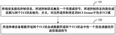
- the terminal device receives control information, the control information triggers a channel or signal, the reception (reception) or monitoring (monitoring) of the control information is related to the two TCI states, and the DCI format corresponding to the control information Does not contain the TCI field;
- the terminal device transmits or receives the channel or signal according to the two TCI states or according to one of the two TCI states.
- a wireless communication method includes:
- the network device sends control information, the control information is related to two TCI states, and the DCI format corresponding to the control information includes the TCI field.
- a wireless communication method comprising:
- the terminal device receives control information, the control information is related to two TCI states, and the DCI format corresponding to the control information includes the TCI field.
- a wireless communication device comprising:
- a receiving unit which receives control information, the control information triggers a channel or signal, the reception or monitoring of the control information is related to the two TCI states, and the control information corresponds to the DCI format does not contain the TCI field;
- a processing unit that transmits or receives the channel or signal according to the two TCI states or according to one of the two TCI states.
- a wireless communication device comprising:
- a sending unit which sends control information, the control information is related to two TCI states, and the DCI format corresponding to the control information includes a TCI field.
- a wireless communication device comprising:
- a receiving unit which receives control information, the control information is related to two TCI states, and the DCI format corresponding to the control information includes a TCI field.
- One of the beneficial effects of the embodiments of the present application is that: on the one hand, when a channel or signal is triggered by control information (not including the TCI field), the TCI state of the channel or signal is determined by the TCI state associated with the control information. Through this method, the mapping relationship between the two TCI states associated with the control information and the TCI state of the signal or channel can be determined, so that the TCI state of the channel or signal is not ambiguous, and the method can reduce the number of TCI states indicated in the control information. Overhead due to the TCI status of the channel or signal.
- the control information contains the TCI field.
- control information can always include the TCI field, and the TCI state of the signal or channel triggered by the control information is indicated by the TCI field contained therein, so that the TCI state of the signal or channel is clarified, and the TCI state of the signal or channel is clarified.
- the TCI status indication of this signal or channel is more flexible.
- FIG. 1 is a schematic diagram of a wireless communication method according to an embodiment of the first aspect of the present application
- FIG. 2 is a schematic diagram of the mapping relationship between the TCI state of the PDCCH and the TCI state of the PDSCH of a single TCI scheduled by the PDCCH;
- 3 is another schematic diagram of the mapping relationship between the TCI state of the PDCCH and the TCI state of the PDSCH of the single TCI scheduled by the PDCCH;
- 4 is another schematic diagram of the mapping relationship between the TCI state of the PDCCH and the TCI state of the PDSCH of the single TCI scheduled by the PDCCH;
- 5 is another schematic diagram of the mapping relationship between the TCI state of the PDCCH and the TCI state of the PDSCH of the single TCI scheduled by the PDCCH;
- FIG. 6 is another schematic diagram of the mapping relationship between the TCI state of the PDCCH and the TCI state of the PDSCH of a single TCI scheduled by the PDCCH;
- FIG. 7 is a schematic diagram of the mapping relationship between the TCI state of the PDCCH and the TCI state of the PDSCH of multiple TCIs scheduled by the PDCCH;
- FIG. 8 is another schematic diagram of the mapping relationship between the TCI state of the PDCCH and the TCI state of the multi-TCI PDSCH scheduled by the PDCCH;
- FIG. 9 is a schematic diagram of a wireless communication method according to an embodiment of the second aspect of the present application.
- Figure 10 is a schematic diagram of the mapping relationship between the TCI state of the PDCCH and the TCI state of the PDSCH of the single TCI scheduled by the PDCCH;
- 11 is a schematic diagram of the mapping relationship between the TCI state of the PDCCH and the TCI state of the PDSCH of the multi-TCI scheduled by the PDCCH;
- FIG. 12 is a schematic diagram of a wireless communication method according to an embodiment of the third aspect of the present application.
- 13 is a schematic diagram of the mapping relationship between the TCI state of the PDCCH and the TCI state of the single-TCI PDSCH scheduled by the PDCCH;
- FIG. 14 is a schematic diagram of the mapping relationship between the TCI state of the PDCCH and the TCI state of the PDSCH of multiple TCIs scheduled by the PDCCH;
- 15 is a schematic diagram of a wireless communication device according to an embodiment of the fourth aspect of the present application.
- 16 is a schematic diagram of a wireless communication device according to an embodiment of the fifth aspect of the present application.
- FIG. 17 is a schematic diagram of a wireless communication apparatus according to an embodiment of the sixth aspect of the present application.
- FIG. 18 is a schematic diagram of a communication system according to an embodiment of the seventh aspect of the present application.
- FIG. 19 is a schematic diagram of a terminal device according to an embodiment of the seventh aspect of the present application.
- FIG. 20 is a schematic diagram of a network device according to an embodiment of the seventh aspect of the present application.
- the terms “first”, “second”, etc. are used to distinguish different elements in terms of numelation, but do not indicate the spatial arrangement or temporal order of these elements, and these elements should not be referred to by these terms restricted.
- the term “and/or” includes any and all combinations of one or more of the associated listed items.
- the terms “comprising”, “including”, “having”, etc. refer to the presence of stated features, elements, elements or components, but do not preclude the presence or addition of one or more other features, elements, elements or components.
- the term "communication network” or “wireless communication network” may refer to a network that conforms to any of the following communication standards, such as Long Term Evolution (LTE, Long Term Evolution), Long Term Evolution Enhanced (LTE-A, LTE- Advanced), Wideband Code Division Multiple Access (WCDMA, Wideband Code Division Multiple Access), High-Speed Packet Access (HSPA, High-Speed Packet Access) and so on.
- LTE Long Term Evolution
- LTE-A Long Term Evolution Enhanced
- WCDMA Wideband Code Division Multiple Access
- High-Speed Packet Access High-Speed Packet Access
- HSPA High-Speed Packet Access
- the communication between devices in the communication system can be carried out according to communication protocols at any stage, for example, including but not limited to the following communication protocols: 1G (generation), 2G, 2.5G, 2.75G, 3G, 4G, 4.5G and future 5G, New Radio (NR, New Radio), etc., and/or other communication protocols currently known or to be developed in the future.
- Network device refers to, for example, a device in a communication system that connects a terminal device to a communication network and provides services for the terminal device.
- Network devices may include but are not limited to the following devices: Base Station (BS, Base Station), Access Point (AP, Access Point), Transceiver Node (TRP, Transmission Reception Point), broadcast transmitter, Mobile Management Entity (MME, Mobile Management Entity), gateway, server, radio network controller (RNC, Radio Network Controller), base station controller (BSC, Base Station Controller) and so on.
- BS Base Station
- AP Access Point
- TRP Transmission Reception Point
- MME Mobile Management Entity
- gateway server
- RNC Radio Network Controller
- BSC Base Station Controller
- the base station may include but is not limited to: Node B (NodeB or NB), evolved Node B (eNodeB or eNB), and 5G base station (gNB), etc., and may also include a remote radio head (RRH, Remote Radio Head) , Remote Radio Unit (RRU, Remote Radio Unit), relay (relay) or low power node (eg femto, pico, etc.).
- RRH Remote Radio Head
- RRU Remote Radio Unit
- relay relay
- low power node eg femto, pico, etc.
- base station may include some or all of their functions, each base station may provide communication coverage for a particular geographic area.
- the term "cell” may refer to a base station and/or its coverage area, depending on the context in which the term is used.
- the term "User Equipment” refers to a device that accesses a communication network through a network device and receives network services, and may also be called “Terminal Equipment” (TE, Terminal Equipment).
- a terminal device may be fixed or mobile, and may also be referred to as a mobile station (MS, Mobile Station), a terminal, a user, a subscriber station (SS, Subscriber Station), an access terminal (AT, Access Terminal), a station, etc. Wait.
- the terminal device may include but is not limited to the following devices: Cellular Phone (Cellular Phone), Personal Digital Assistant (PDA, Personal Digital Assistant), wireless modem, wireless communication device, handheld device, machine type communication device, laptop computer, Cordless phones, smartphones, smart watches, digital cameras, etc.
- Cellular Phone Cellular Phone
- PDA Personal Digital Assistant
- wireless modem wireless communication device
- handheld device machine type communication device
- laptop computer Cordless phones, smartphones, smart watches, digital cameras, etc.
- the terminal device may also be a machine or device that performs monitoring or measurement, such as but not limited to: Machine Type Communication (MTC, Machine Type Communication) terminals, In-vehicle communication terminals, device-to-device (D2D, Device to Device) terminals, machine-to-machine (M2M, Machine to Machine) terminals, etc.
- MTC Machine Type Communication
- D2D Device to Device
- M2M Machine to Machine
- An embodiment of the present application provides a wireless communication method, which is described from the side of a terminal device.
- FIG. 1 is a schematic diagram of a wireless communication method according to an embodiment of the present application. Please refer to FIG. 1. The method includes:
- the terminal device receives control information, the control information triggers a channel or signal, the reception (reception) or monitoring (monitoring) of the control information is related to two TCI states, and corresponding to the control information DCI format does not contain the TCI field;
- the terminal device sends or receives the channel or signal according to the two TCI states or according to one of the two TCI states.
- the TCI state of the channel or signal is determined by the TCI state associated with the control information.
- the method can determine the mapping relationship between the two TCI states associated with the control information and the TCI state of the signal or channel, so as to avoid the TCI state of the channel or signal being ambiguous, and the method can reduce the number of TCI states in the control information. Overhead incurred to indicate the TCI status of this channel or signal.
- the above-mentioned channel or signal is related to at least one of the above-mentioned two TCI states.
- the terminal device can transmit or receive the channel or signal according to the two TCI states or according to one of the two TCI states.
- one of the above two TCI states is the first TCI state indicated by the MAC-CE command in the TCI states of the control resource set (CORESET) used for receiving or monitoring the above control information.
- the terminal device sends or receives the above-mentioned channel or signal according to the first TCI state.
- the TCI state of the channel or signal triggered by the above control information is determined by the first TCI state indicated by the MAC-CE signaling. Thereby, the TCI state of the above-mentioned channel or signal can be flexibly changed.
- one of the above-mentioned two TCI states is the TCI state with the lowest ID among the TCI states of the control resource set (CORESET) used for receiving or monitoring the above-mentioned control information.
- the terminal device transmits or receives the above-mentioned channel or signal according to the TCI state of the lowest ID.
- the TCI state of the channel/signal triggered by the above control information is determined according to the TCI state with the lowest associated ID. Therefore, the TCI state of the above-mentioned channel or signal can be directly determined through the TCI state ID, thereby avoiding additional signaling overhead.
- one of the above two TCI states is a TCI state applied to the first control resource set indicated by RRC signaling in the two control resource sets used for receiving or monitoring the above control information.
- the terminal device sends or receives the above-mentioned channel or signal according to the TCI state.
- the TCI state of the channel or signal triggered by the above control information is determined by the TCI state of the first CORESET indicated by the RRC signaling. Thereby, the TCI state of the above-mentioned channel or signal can be flexibly changed.
- one of the above two TCI states is a TCI state applied to the control resource set with the lowest ID among the two control resource sets for receiving or monitoring the above control information.
- the terminal device sends or receives the above-mentioned channel or signal according to the TCI state.
- the TCI state of the channel or signal triggered by the above control information is determined by the TCI state of the relevant CORESET with the lowest ID. Therefore, the TCI state of the above-mentioned channel or signal can be directly determined by the ID of the associated CORESET, avoiding additional signaling overhead.
- one of the above two TCI states is a TCI state corresponding to the first search space set indicated by RRC signaling in the two search space sets used for receiving or monitoring the above control information.
- the terminal device sends or receives the above-mentioned channel or signal according to the TCI state.
- the TCI state of the channel or signal triggered by the above control information is determined by the TCI state of the first search space set indicated by the RRC signaling. Thereby, the TCI state of the above-mentioned channel or signal can be flexibly changed.
- one of the above two TCI states is a TCI state corresponding to the search space set with the lowest ID in the two search space sets for receiving or monitoring the above control information.
- the terminal device sends or receives the above-mentioned channel or signal according to the TCI state.
- the TCI state of the channel or signal triggered by the above control information is determined by the TCI state of the relevant search space set with the lowest ID. Therefore, the TCI state of the above-mentioned channel or signal can be directly determined by the ID of the associated search space set, avoiding additional signaling overhead.
- one of the above-mentioned two TCI states is a TCI state applied to the time-frequency resource used for receiving or monitoring the above-mentioned control information.
- the terminal device sends or receives the above-mentioned channel or signal according to the TCI state.
- the TCI state of the channel or signal triggered by the control information is determined by receiving or monitoring the time-frequency resource corresponding to the above-mentioned control information. Therefore, the TCI state of the above channel or signal can be directly determined through the above time-frequency resource, thereby avoiding additional signaling overhead.
- the time-frequency resource used for receiving or monitoring control information may be the earliest symbol used for receiving or monitoring control information; it may also be the lowest index (index) used for receiving or monitoring control information. ) of the PRB (Physical Recourse Block, physical resource block); it may also be the PRB with the lowest index (index) in the earliest symbol used for the reception or monitoring of the control information.
- PRB Physical Recourse Block, physical resource block
- the above-mentioned channels or signals are downlink channels or signals, such as PDSCH or CSI-RS (Channel State Information-Reference Signal, channel state information reference signal), etc.; in some embodiments Among them, the above channel or signal is an uplink channel or signal, such as PUSCH (Physical Uplink Shared Channel, Physical Uplink Shared Channel), PUCCH (Physical Uplink Control Channel, Physical Uplink Control Channel), and/or SRS (Sounding Reference Signal, detection reference signal) etc.
- PUSCH Physical Uplink Shared Channel, Physical Uplink Shared Channel
- PUCCH Physical Uplink Control Channel
- SRS Sounding Reference Signal, detection reference signal
- the PDSCH is related to a first TCI state, and the first TCI state may be at least one of the following:
- the TCI state applied to the time-frequency resources used to receive or monitor the above control information is the TCI state applied to the time-frequency resources used to receive or monitor the above control information.
- the time-frequency resource used for the reception or monitoring of the control information may be the earliest symbol used for the reception or monitoring of the control information, or the lowest index used for the reception or monitoring of the control information (index) PRB, or the PRB with the lowest index (index) within the earliest symbol used for reception or monitoring of the control information.
- index index
- the present application is not limited to this.
- the PDSCH is also related to a second TCI state, and the second TCI state may be a TCI state other than the foregoing first TCI state among the foregoing two TCI states.
- the second TCI state is determined by the MAC - The second TCI state indicated by the CE command.
- the first TCI state is the TCI state with the lowest ID in the TCI states of the control resource set (CORESET) used to receive or monitor the control information
- the second TCI state is used to receive or monitor the control information.
- the above-mentioned channel or signal is related to two TCI states, for example, a scenario of multi-TRP PDSCH.
- the terminal device may determine, according to RRC signaling or the DCI field of the above-mentioned DCI format, whether to send or receive the above-mentioned channel or signal according to the above-mentioned two TCI states, or to send or receive the above-mentioned channel or signal according to one of the above-mentioned two TCI states.
- the above channels or signals will be received.
- the above-mentioned RRC signaling is used to indicate whether the above-mentioned channel or signal is related to one TCI state or two TCI states.
- the DCI field of the above-mentioned DCI format may be the TDRA (Time Domain Resource Allocation, time domain resource allocation) field of the above-mentioned DCI format.
- TDRA Time Domain Resource Allocation, time domain resource allocation
- a time offset (time offset) between the above-mentioned control information and the above-mentioned channel or signal is greater than or equal to a predefined time period (pre-determined time period), for example, the above-mentioned time offset is greater than or equal to Equal to timeDurationForQCL.
- the terminal device can determine the QCL parameter of the above channel or signal according to the QCL parameter associated with the above control information.
- timeDurationForQCL you can refer to related technologies, and the description is omitted here.
- FIG. 2 is a schematic diagram of a mapping relationship between a TCI state of a PDCCH and a TCI state of a PDSCH of a single TCI scheduled by the PDCCH.
- the UE receives a PDCCH (control information) associated with two TCI states in time slot n, and the PDCCH schedules one PDSCH (channel or signal).
- the scheduling offset between the PDCCH and PDSCH is greater than or equal to timeDurationForQCL.
- SCS 60 kHz
- timeDurationForQCL 7 symbols.
- the DCI format corresponding to the PDCCH does not include the TCI field;
- the search space corresponding to the PDCCH is SS#1;
- the CORESET corresponding to the search space SS#1 is CORESET#1;
- the CORESET#1 is activated by the MAC-CE activation signaling
- Two TCI states namely TCI#1 and TCI#2, wherein the first TCI state activated by the MAC-CE activation signaling is TCI#1, and the second TCI state activated by the MAC-CE activation signaling is TCI# 2;
- the TCI state applied in the first symbol of time slot n is TCI #1
- the TCI state applied in the second symbol of time slot n is TCI #2.
- the UE may determine that the PDSCH is associated with a TCI state according to the following method 1 or method 2:
- Method 1 Before the UE receives the above-mentioned PDCCH and PDSCH, the UE receives an RRC signaling, and the UE determines that the above-mentioned PDSCH is associated with a TCI state according to the RRC signaling;
- Method 2 The UE determines that the above PDSCH is associated with a TCI state according to the TDRA field in the DCI format corresponding to the above PDCCH.
- the UE may determine the TCI state of the above PDSCH according to the following method:
- Method #1-1 Determine the TCI state of the PDSCH according to the first TCI state used to receive the above-mentioned PDCCH. For example, the reception of the above-mentioned PDCCH is based on the TCI state of the CORESET#1 corresponding to the above-mentioned PDCCH, and the TCI state of the PDSCH is determined by the first TCI state (TCI#1) activated by the MAC-CE for the CORESET#1.
- Method #1-2 Determine the TCI state of the PDSCH according to the second TCI state used to receive the above-mentioned PDCCH. For example, the reception of the above-mentioned PDCCH is based on the TCI state of CORESET#1 corresponding to the above-mentioned PDCCH, and the TCI state of the PDSCH is determined by the second TCI state (TCI#2) activated by the MAC-CE for CORESET#1.
- Method #2-1 Determine the TCI state of the PDSCH according to the TCI state of the smallest ID for receiving the above-mentioned PDCCH. For example, the reception of the above PDCCH is based on the TCI state of the CORESET#1 corresponding to the above PDCCH, and the TCI state of the PDSCH is determined by the TCI state (TCI#1) with the smallest ID activated by the MAC-CE for CORESET#1.
- Method #2-2 Determine the TCI state of the PDSCH according to the TCI state used to receive the maximum ID of the PDCCH. For example, the reception of the above-mentioned PDCCH is based on the TCI state of the CORESET#1 corresponding to the above-mentioned PDCCH, and the TCI state of the PDSCH is determined by the TCI state (TCI#2) with the largest ID activated by the MAC-CE for CORESET#1.
- Method #3-1 Determine the TCI state of the PDSCH according to the TCI state applied for receiving the earliest symbol of the PDCCH.
- the earliest received symbol of the PDCCH is the first symbol of time slot n
- the TCI state of the PDSCH is determined by the TCI state (TCI#1) applied by the PDCCH to the symbol.
- Method #3-2 Determine the TCI state of the PDSCH according to the TCI state applied for the latest symbol for receiving the above-mentioned PDCCH.
- the latest received symbol of the PDCCH is the second symbol of the time slot n
- the TCI state of the PDSCH is determined by the TCI state (TCI#2) applied by the PDCCH on this symbol.
- FIG. 3 is another schematic diagram of the mapping relationship between the TCI state of the PDCCH and the TCI state of the single-TCI PDSCH scheduled by the PDCCH.
- the UE receives a PDCCH (control information) in time slot n, and the PDCCH schedules a PDSCH (channel or signal).
- the scheduling offset between the PDCCH and PDSCH is greater than or equal to timeDurationForQCL.
- SCS 60 kHz
- timeDurationForQCL 7 symbols.
- the DCI format corresponding to the PDCCH does not include the TCI field;
- the search space corresponding to the PDCCH is SS#1;
- the CORESET corresponding to the search space SS#1 is CORESET#1;
- the CORESET#1 is activated by the MAC-CE activation signaling
- Two TCI states namely TCI#1 and TCI#2, wherein the first TCI state activated by the MAC-CE activation signaling is TCI#1, and the second TCI state activated by the MAC-CE activation signaling is TCI# 2;
- CORESET#1 its frequency domain resources are divided into two parts, wherein the TCI state applied to the higher frequency part is TCI#1, and the TCI state applied to the lower frequency part is TCI #2.
- the UE may determine that the PDSCH is associated with a TCI state according to the following method 1 or method 2:
- Method 1 Before the UE receives the above-mentioned PDCCH and PDSCH, the UE receives an RRC signaling, and the UE determines that the above-mentioned PDSCH is associated with a TCI state according to the RRC signaling;
- Method 2 The UE determines that the above PDSCH is associated with a TCI state according to the TDRA field in the DCI format corresponding to the above PDCCH.
- the UE may determine the TCI state of the above PDSCH according to the following method:
- Method #1-1 Determine the TCI state of the PDSCH according to the first TCI state used to receive the above-mentioned PDCCH. For example, the reception of the above-mentioned PDCCH is based on the TCI state of the CORESET#1 corresponding to the above-mentioned PDCCH, and the TCI state of the PDSCH is determined by the first TCI state (TCI#1) activated by the MAC-CE for CORESET#1.
- Method #1-2 Determine the TCI state of the PDSCH according to the second TCI state used to receive the above-mentioned PDCCH. For example, the reception of the above-mentioned PDCCH is based on the TCI state of CORESET#1 corresponding to the above-mentioned PDCCH, and the TCI state of the PDSCH is determined by the second TCI state (TCI#2) activated by the MAC-CE for CORESET#1.
- Method #2-1 Determine the TCI state of the PDSCH according to the TCI state of the smallest ID for receiving the above-mentioned PDCCH. For example, the reception of the above-mentioned PDCCH is based on the TCI state of the CORESET#1 corresponding to the above-mentioned PDCCH, and the TCI state of the PDSCH is determined by the TCI state (TCI#1) with the smallest ID activated by the MAC-CE for CORESET#1.
- Method #2-2 Determine the TCI state of the PDSCH according to the TCI state used to receive the maximum ID of the PDCCH. For example, the reception of the above-mentioned PDCCH is based on the TCI state of the CORESET#1 corresponding to the above-mentioned PDCCH, and the TCI state of the PDSCH is determined by the TCI state (TCI#2) with the largest ID activated by the MAC-CE for CORESET#1.
- Method #3-1 Determine the TCI state (TCI#1) of the PDSCH according to the TCI state (TCI#1) applied to the PRB with the highest corresponding frequency (eg, the PRB with the highest ID) in the frequency domain resources for receiving the PDCCH.
- Method #3-2 Determine the TCI state (TCI#2) of the PDSCH according to the TCI state (TCI#2) applied to the PRB with the lowest corresponding frequency (eg, the PRB with the lowest ID) in the frequency domain resources for receiving the PDCCH.
- Method #4 Determine the TCI state (TCI#2) of the PDSCH according to the TCI state (TCI#2) applied to the PRB with the lowest frequency (for example, the PRB with the lowest ID) in the earliest symbol in the time-frequency resource receiving the above-mentioned PDCCH .
- the earliest received symbol of the PDCCH is the first symbol of time slot n
- the TCI state of the PDSCH is determined by the TCI state applied to the lowest PRB corresponding to the PDCCH on the symbol (TCI#2).
- FIG. 2 shows the case of time division multiplexing (TDM)
- FIG. 3 shows the case of frequency division multiplexing (FDM).
- FIG. 4 is another schematic diagram of the mapping relationship between the TCI state of the PDCCH and the TCI state of the single-TCI PDSCH scheduled by the PDCCH.
- the UE receives a PDCCH (control information) in time slot n, and the PDCCH schedules a PDSCH (channel or signal).
- the scheduling offset between the PDCCH and PDSCH is greater than or equal to timeDurationForQCL.
- SCS 60 kHz
- timeDurationForQCL 7 symbols.
- the DCI format corresponding to the PDCCH does not include the TCI field;
- the PDCCH includes two parts, namely PDCCH#rep1 and PDCCH#rep2, wherein PDCCH#rep1 and PDCCH#rep2 correspond to the same DCI bits;
- the search spaces corresponding to PDCCH are respectively are SS#1 and SS#2, where SS#1 is located in the first symbol of time slot n, and SS#2 is located in the third symbol of time slot n.
- the UE knows SS#1 and SS#2 in advance are related, SS#1 corresponds to the first SS, SS#2 corresponds to the second SS, and the two SSs can receive a repetition corresponding to a PDCCH respectively; according to the configuration of the RRC signaling, the search spaces SS#1 and The CORESET corresponding to SS#2 is CORESET#1; the CORESET#1 activates two TCI states, namely TCI#1 and TCI#2, by the MAC-CE activation signaling.
- TCI#1 One TCI state is TCI#1, wherein SS#2 corresponds to TCI#1; the second TCI state activated by the MAC-CE activation signaling is TCI#2, wherein SS#1 corresponds to TCI#2;
- the TCI state applied to the first symbol of slot n is TCI #1, and the TCI state applied to the third symbol of slot n is TCI #2.
- the UE may determine that the PDSCH is associated with a TCI state according to the following method 1 or method 2:
- Method 1 Before the UE receives the above-mentioned PDCCH and PDSCH, the UE receives an RRC signaling, and the UE determines that the above-mentioned PDSCH is associated with a TCI state according to the RRC signaling;
- Method 2 The UE determines that the above PDSCH is associated with a TCI state according to the TDRA field in the DCI format corresponding to the above PDCCH.
- the UE may determine the TCI state of the above PDSCH according to the following method:
- Method 1-1 Determine the TCI state of the PDSCH according to the first TCI state used for monitoring the above-mentioned PDCCH.
- the monitoring of the above-mentioned PDCCH is based on one of the two TCI states of CORESET#1 corresponding to the above-mentioned PDCCH, and the TCI state of the PDSCH is determined by the first TCI state (TCI#1) activated by the MAC-CE for CORESET#1 .
- Method 1-2 Determine the TCI state of the PDSCH according to the second TCI state used for monitoring the above-mentioned PDCCH.
- the monitoring of the above-mentioned PDCCH is based on one of the two TCI states of CORESET#1 corresponding to the above-mentioned PDCCH, and the TCI state of the PDSCH is determined by the second TCI state (TCI#2) activated by the MAC-CE for CORESET#1 .
- Method 2-1 Determine the TCI state of the PDSCH according to the TCI state with the smallest ID used to monitor the PDCCH. For example, the monitoring of the above-mentioned PDCCH is based on one of the two TCI states of CORESET#1 corresponding to the above-mentioned PDCCH, then the TCI state of the PDSCH is the TCI state (TCI#1) with the smallest ID activated by the MAC-CE for CORESET#1. Decide.
- Method 2-2 Determine the TCI state of the PDSCH according to the TCI state with the largest ID used for monitoring the above-mentioned PDCCH.
- the monitoring of the above-mentioned PDCCH is based on one of the two TCI states of CORESET#1 corresponding to the above-mentioned PDCCH, and the TCI state of the PDSCH is the TCI state (TCI#2) with the largest ID activated by the MAC-CE for CORESET#1. Decide.
- Method 3-1 Determine the TCI state of the PDSCH according to the TCI state of the first SS for monitoring the above-mentioned PDCCH.
- the monitoring of the above-mentioned PDCCH is based on one of the two SSs corresponding to the above-mentioned PDCCH, and the TCI state of the PDSCH is determined by the TCI state (TCI#1) of the first SS (SS#1) activated by the MAC-CE for CORESET#1 )Decide.
- Method 3-2 Determine the TCI state of the PDSCH according to the TCI state of the second SS for monitoring the above-mentioned PDCCH.
- the monitoring of the above-mentioned PDCCH is based on one of the two SSs corresponding to the above-mentioned PDCCH, and the TCI state of the PDSCH is the TCI state (TCI#2) of the second SS (SS#2) activated by the MAC-CE for CORESET#1 )Decide.
- Method 4-1 Determine the TCI state of the PDSCH according to the TCI state of the SS with the smallest ID for monitoring the above-mentioned PDCCH.
- the monitoring of the above-mentioned PDCCH is based on one of the two SSs corresponding to the above-mentioned PDCCH, and the TCI state of the PDSCH is activated by the MAC-CE for the TCI state of the SS with the smallest ID (SS#1) (SS#1). TCI#1) decided.
- Method 4-2 Determine the TCI state of the PDSCH according to the TCI state of the SS with the largest ID for monitoring the above-mentioned PDCCH.
- the monitoring of the above PDCCH is based on one of the two SSs corresponding to the above PDCCH, and the TCI state of the PDSCH is activated by the MAC-CE for the TCI state of the SS with the largest ID (SS#2) (SS#2). TCI#2) decided.
- Method 5-1 Determine the TCI state of the PDSCH according to the TCI state (TCI#1) applied for monitoring the earliest symbol of the PDCCH.
- TCI#1 the TCI state applied for monitoring the earliest symbol of the PDCCH.
- the earliest symbol corresponding to the monitoring of the PDCCH is the first symbol of the time slot n
- the TCI state of the PDSCH is determined by the TCI state applied by the PDCCH to the symbol.
- Method 5-2 Determine the TCI state of the PDSCH according to the TCI state (TCI#2) applied to the latest symbol used for monitoring the above-mentioned PDCCH.
- TCI#2 the latest symbol corresponding to the above-mentioned PDCCH monitoring is the third symbol of time slot n
- the TCIT state of the PDSCH is determined by the TCI state applied by the PDCCH on this symbol.
- FIG. 5 is another schematic diagram of the mapping relationship between the TCI state of the PDCCH and the TCI state of the single-TCI PDSCH scheduled by the PDCCH.
- the UE receives a PDCCH (control information) in time slot n, and the PDCCH schedules a PDSCH (channel or signal).
- the scheduling offset between the PDCCH and PDSCH is greater than or equal to timeDurationForQCL.
- SCS 60 kHz
- timeDurationForQCL 7 symbols.
- the DCI format corresponding to the PDCCH does not include the TCI field; the PDCCH includes two parts, namely PDCCH#rep1 and PDCCH#rep2, wherein PDCCH#rep1 and PDCCH#rep2 correspond to the same DCI bits; the search space corresponding to the PDCCH is SS#1; according to the configuration of the RRC signaling, the search space SS#1 corresponds to CORESET#1 and CORESET#2. For example, the UE knows in advance that CORESET#1 and CORESET#2 are associated, and CORESET#1 corresponds to TCI#2. CORESET#2 corresponds to TCI#1.
- the UE may determine that the PDSCH is associated with a TCI state according to the following method 1 or method 2:
- Method 1 Before the UE receives the above-mentioned PDCCH and PDSCH, the UE receives an RRC signaling, and the UE determines that the above-mentioned PDSCH is associated with a TCI state according to the RRC signaling;
- Method 2 The UE determines that the above PDSCH is associated with a TCI state according to the TDRA field in the DCI format corresponding to the above PDCCH.
- the UE may determine the TCI state of the above PDSCH according to the following method:
- Method 2-1 Determine the TCI state of the PDSCH according to the TCI state with the smallest ID used to monitor the PDCCH. For example, the monitoring of the above-mentioned PDCCH is based on one of the two TCI states of CORESET#1 and CORESET#2 corresponding to the above-mentioned PDCCH, and the TCI state of the PDSCH is activated by the MAC-CE for CORESET#1 and CORESET#2 with the smallest ID The TCI status (TCI#1) is determined.
- Method 2-2 Determine the TCI state of the PDSCH according to the TCI state with the largest ID used for monitoring the above-mentioned PDCCH.
- the monitoring of the above-mentioned PDCCH is based on one of the two TCI states of CORESET#1 and CORESET#2 corresponding to the above-mentioned PDCCH, and the TCI state of the PDSCH is activated by the MAC-CE for CORESET#1 and CORESET#2 with the largest ID
- the TCI status (TCI#2) is determined.
- Method 3-1 Determine the TCI state of the PDSCH according to the TCI state of the first CORESET for monitoring the above-mentioned PDCCH.
- the monitoring of the above-mentioned PDCCH is based on one of the two CORESETs corresponding to the above-mentioned PDCCH, and the TCI state of the PDSCH is determined by the TCI state (TCI#2) applied to the first CORESET (CORESET#1).
- Method 3-2 Determine the TCI state of the PDSCH according to the TCI state of the second CORESET for monitoring the above PDCCH.
- the monitoring of the above-mentioned PDCCH is based on one of the two CORESETs corresponding to the above-mentioned PDCCH, and the TCI state of the PDSCH is determined by the TCI state (TCI#1) applied to the second CORESET (CORESET#2).
- Method 4-1 Determine the TCI state of the PDSCH according to the TCI state of the CORESET for monitoring the above-mentioned PDCCH with the smallest ID.
- the monitoring of the above-mentioned PDCCH is based on one of the two CORESETs corresponding to the above-mentioned PDCCH, and the TCI state of the PDSCH is determined by the TCI state (TCI#2) applied to the CORESET (CORESET#1) with the smallest ID.
- Method 4-2 Determine the TCI state of the PDSCH according to the TCI state of the CORESET with the largest ID for monitoring the above-mentioned PDCCH.
- the monitoring of the above-mentioned PDCCH is based on one of the two CORESETs corresponding to the above-mentioned PDCCH, and the TCI state of the PDSCH is determined by the TCI state (TCI#1) applied to the CORESET (CORESET#2) with the largest ID.
- Method 5-1 Determine the TCI state of the PDSCH according to the TCI state (TCI#2) applied to the PRB with the lowest frequency (eg, the PRB with the lowest ID) in the frequency domain resource for monitoring the PDCCH.
- Method 5-2 Determine the TCI state of the PDSCH according to the TCI state (TCI#1) applied to the PRB with the highest frequency (eg, the PRB with the highest ID) in the frequency domain resource for monitoring the PDCCH.
- FIG. 6 is another schematic diagram of the mapping relationship between the TCI state of the PDCCH and the TCI state of the PDSCH of a single TCI scheduled by the PDCCH.
- the UE receives a PDCCH (control information) in time slot n, and the PDCCH schedules a PDSCH (channel or signal).
- the scheduling offset between the PDCCH and PDSCH is greater than or equal to timeDurationForQCL.
- SCS 60 kHz
- timeDurationForQCL 7 symbols.
- the DCI format corresponding to the PDCCH does not include the TCI field;
- the PDCCH includes two parts, namely PDCCH#rep1 and PDCCH#rep2, wherein PDCCH#rep1 and PDCCH#rep2 correspond to the same DCI bits;
- the search spaces corresponding to PDCCH are respectively are SS#1 and SS#2, where SS#1 is located in the first symbol of time slot n, and SS#2 is located in the third symbol of time slot n.
- the UE knows SS#1 and SS#2 in advance are related, SS#1 corresponds to the first SS, SS#2 corresponds to the second SS, and the two SSs can receive a repetition corresponding to a PDCCH respectively; according to the configuration of the RRC signaling, the search spaces SS#1 and SS#2 corresponds to CORESET#2 and CORESET#1 respectively, for example, for example, RRC signaling indicates that CORESET#1 corresponds to the first CORESET, and CORESET#2 corresponds to the second CORESET; the TCI applied in the first symbol of time slot n The state is TCI#1, and the TCI state applied in the third symbol of slot n is TCI#2.
- the UE may determine that the PDSCH is associated with a TCI state according to the following method 1 or method 2:
- Method 1 Before the UE receives the above-mentioned PDCCH and PDSCH, the UE receives an RRC signaling, and the UE determines that the above-mentioned PDSCH is associated with a TCI state according to the RRC signaling;
- Method 2 The UE determines that the above PDSCH is associated with a TCI state according to the TDRA field in the DCI format corresponding to the above PDCCH.
- the UE may determine the TCI state of the above PDSCH according to the following method:
- Method 1-1 Determine the TCI state of the PDSCH according to the first TCI state used for monitoring the above-mentioned PDCCH.
- the monitoring of the above-mentioned PDCCH is based on one of the two TCI states of CORESET#1 corresponding to the above-mentioned PDCCH, and the TCI state of the PDSCH is determined by the first TCI state (TCI#1) activated by the MAC-CE for CORESET#1 .
- Method 1-2 Determine the TCI state of the PDSCH according to the second TCI state used for monitoring the above-mentioned PDCCH.
- the monitoring of the above-mentioned PDCCH is based on one of the two TCI states of CORESET#1 corresponding to the above-mentioned PDCCH, and the TCI state of the PDSCH is determined by the second TCI state (TCI#2) activated by the MAC-CE for CORESET#1 .
- Method 2-1 Determine the TCI state of the PDSCH according to the TCI state with the smallest ID used to monitor the PDCCH.
- the monitoring of the above-mentioned PDCCH is based on one of the two TCI states of CORESET#1 corresponding to the above-mentioned PDCCH, and the TCI state of the PDSCH is the TCI state (TCI#1) with the smallest ID activated by the MAC-CE for CORESET#1. Decide.
- Method 2-2 Determine the TCI state of the PDSCH according to the TCI state with the largest ID used for monitoring the above-mentioned PDCCH.
- the monitoring of the above-mentioned PDCCH is based on one of the two TCI states of CORESET#1 corresponding to the above-mentioned PDCCH, and the TCI state of the PDSCH is the TCI state (TCI#2) with the largest ID activated by the MAC-CE for CORESET#1. Decide.
- Method 3-1 Determine the TCI state of the PDSCH according to the TCI state of the first CORESET for monitoring the above-mentioned PDCCH.
- the monitoring of the above-mentioned PDCCH is based on the first CORESET among the two CORESETs corresponding to the above-mentioned PDCCH, and the TCI state of the PDSCH is determined by the TCI state (TCI#1) applied by CORESET#1.
- Method 3-2 Determine the TCI state of the PDSCH according to the TCI state of the second CORESET for monitoring the above PDCCH.
- the monitoring of the above-mentioned PDCCH is based on the second CORESET among the two CORESETs corresponding to the above-mentioned PDCCH, and the TCI state of the PDSCH is determined by the TCI state (TCI#2) applied by CORESET#2.
- Method 4-1 Determine the TCI state of the PDSCH according to the TCI state of the CORESET for monitoring the above-mentioned PDCCH with the smallest ID. For example, the monitoring of the above-mentioned PDCCH is based on the one with the smaller ID among the two CORESETs corresponding to the above-mentioned PDCCH, and the TCI state of the PDSCH is determined by the TCI state (TCI#1) applied by CORESET#1.
- Method 4-2 Determine the TCI state of the PDSCH according to the TCI state of the CORESET with the largest ID for monitoring the above-mentioned PDCCH.
- the monitoring of the above-mentioned PDCCH is based on the one with the larger ID among the two CORESETs corresponding to the above-mentioned PDCCH, and the TCI state of the PDSCH is determined by the TCI state (TCI#2) applied by the CORESET#2.
- Method 5-1 Determine the TCI state of the PDSCH according to the TCI state (TCI#1) applied for monitoring the earliest symbol of the PDCCH.
- TCI#1 the TCI state applied for monitoring the earliest symbol of the PDCCH.
- the earliest symbol corresponding to the above-mentioned PDCCH monitoring is the first symbol of time slot n
- the TCI state of the PDSCH is determined by the TCI state applied by the PDCCH to the symbol.
- Method 5-2 Determine the TCI state of the PDSCH according to the TCI state (TCI#2) applied to the latest symbol used for monitoring the above-mentioned PDCCH.
- TCI#2 the latest symbol corresponding to the above-mentioned PDCCH monitoring is the third symbol of time slot n, and the TCI state of the PDSCH is determined by the TCI state applied by the PDCCH on this symbol.
- the PDCCH has repetitions. And, in the example of Figure 4, there are two sets of search spaces and one CORESET, in the example of Figure 5, there are one set of search spaces and two CORESETs, and in the example of Figure 6, there are two sets of search spaces and Two CORESETs.
- FIG. 7 is a schematic diagram of the mapping relationship between the TCI state of the PDCCH and the TCI state of the PDSCH with multiple TCIs scheduled by the PDCCH.
- the UE receives one PDCCH (control information) associated with two TCI states in time slot n, and the PDCCH schedules one PDSCH (channel or signal).
- the scheduling offset between the PDCCH and PDSCH is greater than or equal to timeDurationForQCL.
- SCS 60 kHz
- timeDurationForQCL 7 symbols.
- the DCI format corresponding to the PDCCH does not include the TCI field;
- the search space corresponding to the PDCCH is SS#1;
- the CORESET corresponding to the search space SS#1 is CORESET#1;
- CORESET#1 is activated by the MAC-CE activation signaling for two TCI states, that is, TCI#1 and TCI#2, wherein the first TCI state activated by the MAC-CE activation signaling is TCI#1, and the second TCI state activated by the MAC-CE activation signaling is TCI#2;
- the TCI state applied in the first symbol of time slot n is TCI #1, and the TCI state applied in the second symbol of time slot n is TCI #2.
- the UE may determine that the PDSCH is associated with two TCI states according to the following method 1 or method 2:
- Method 1 Before the UE receives the above-mentioned PDCCH and PDSCH, the UE receives an RRC signaling, and the UE determines that the above-mentioned PDSCH is associated with two TCI states according to the RRC signaling;
- Method 2 The UE determines that the above PDSCH is associated with two TCI states according to the TDRA field in the DCI format corresponding to the above PDCCH.
- the UE can determine the TCI state of Rep#1 of the above PDSCH according to the following method:
- Method 1-1 Determine the TCI state of Rep#1 of the PDSCH according to the first TCI state used for receiving the above-mentioned PDCCH. For example, the reception of the above PDCCH is based on the TCI state of CORESET#1 corresponding to the above PDCCH, and the TCI state of Rep#1 of the PDSCH is determined by the first TCI state (TCI#1) activated by the MAC-CE for CORESET#1.
- Method 1-2 Determine the TCI state of Rep#1 of the PDSCH according to the second TCI state used to receive the above-mentioned PDCCH. For example, the reception of the above-mentioned PDCCH is based on the TCI state of CORESET#1 corresponding to the above-mentioned PDCCH, and the TCI state of Rep#1 of the PDSCH is determined by the second TCI state (TCI#2) activated by the MAC-CE for CORESET#1.
- TCI#2 the second TCI state activated by the MAC-CE for CORESET#1.
- Method 2-1 Determine the TCI state of Rep#1 of the PDSCH according to the TCI state used to receive the minimum ID of the PDCCH. For example, the reception of the above-mentioned PDCCH is based on the TCI state of CORESET#1 corresponding to the above-mentioned PDCCH, and the TCI state of Rep#1 of the PDSCH is determined by the TCI state (TCI#1) with the smallest ID activated by the MAC-CE for CORESET#1 .
- Method 2-2 Determine the TCI state of Rep#1 of the PDSCH according to the TCI state used to receive the maximum ID of the PDCCH. For example, the reception of the above-mentioned PDCCH is based on the TCI state of CORESET#1 corresponding to the above-mentioned PDCCH, and the TCI state of Rep#1 of the PDSCH is determined by the TCI state (TCI#2) with the largest ID activated by the MAC-CE for CORESET#1 .
- Method 3-1 Determine the TCI state of Rep#1 of the PDSCH according to the TCI state (TCI#1) applied for receiving the earliest symbol of the PDCCH.
- TCI#1 the TCI state applied to the symbol by the PDCCH.
- Method 3-2 Determine the TCI state of Rep#1 of the PDSCH according to the TCI state (TCI#2) applied for receiving the latest symbol of the PDCCH.
- TCI#2 the latest received symbol of the above-mentioned PDCCH is the second symbol of time slot n
- the TCI state of Rep#1 of the PDSCH is determined by the TCI state applied to this symbol by the PDCCH.
- the UE may determine the TCI state of Rep#2 of the above PDSCH according to the following method:
- the UE can choose between TCI#1 and TCI#2 not to use TCI#1 and TCI#2.
- the TCI state of Rep#1 of the PDSCH is used as the TCI state of Rep#2 of the PDSCH.
- the TCI state of Rep#1 of the PDSCH is determined to be TCI#1 according to the aforementioned method 1-1
- the TCI state of Rep#2 of the PDSCH is determined to be TCI#2.
- the TCI state of Rep#1 of the PDSCH is determined to be TCI#2 according to the foregoing method 1-2
- the TCI state of Rep#2 of the PDSCH is determined to be TCI#1.
- FIG. 7 shows the case of TDM, the case of FDM is similar to TDM, and analogy can be made according to the method of FIG. 3 , and the description is omitted here.
- FIG. 8 is another schematic diagram of the mapping relationship between the TCI state of the PDCCH and the TCI state of the multi-TCI PDSCH scheduled by the PDCCH.
- the UE receives a PDCCH (control information) at slot n, and the PDCCH schedules a PDSCH (channel or signal).
- the scheduling offset between the PDCCH and PDSCH is greater than or equal to timeDurationForQCL.
- SCS 60 kHz
- timeDurationForQCL 7 symbols.
- the DCI format corresponding to the PDCCH does not include the TCI field;
- the PDCCH includes two parts, namely PDCCH#rep1 and PDCCH#rep2, wherein PDCCH#rep1 and PDCCH#rep2 correspond to the same DCI bits;
- the search spaces corresponding to PDCCH are respectively are SS#1 and SS#2, where SS#1 is located in the first symbol of time slot n, and SS#2 is located in the third symbol of time slot n.
- the UE knows SS#1 and SS#2 in advance are related, SS#1 corresponds to the first SS, SS#2 corresponds to the second SS, and the two SSs can receive a repetition corresponding to a PDCCH respectively; according to the configuration of the RRC signaling, the search spaces SS#1 and The CORESET corresponding to SS#2 is CORESET#1; the CORESET#1 activates two TCI states, namely TCI#1 and TCI#2, by the MAC-CE activation signaling.
- TCI#1 One TCI state is TCI#1, wherein SS#2 corresponds to TCI#1; the second TCI state activated by the MAC-CE activation signaling is TCI#2, wherein SS#1 corresponds to TCI#2;
- the TCI state applied to the first symbol of slot n is TCI #1, and the TCI state applied to the third symbol of slot n is TCI #2.
- the UE may determine that the PDSCH is associated with two TCI states according to the following method 1 or method 2:
- Method 1 Before the UE receives the above-mentioned PDCCH and PDSCH, the UE receives an RRC signaling, and the UE determines that the above-mentioned PDSCH is associated with two TCI states according to the RRC signaling;
- Method 2 The UE determines that the above PDSCH is associated with two TCI states according to the TDRA field in the DCI format corresponding to the above PDCCH.
- the UE can determine the TCI state of Rep#1 of the above PDSCH according to the following method:
- Method 1-1 Determine the TCI state of Rep#1 of the PDSCH according to the first TCI state used for monitoring the above-mentioned PDCCH.
- the monitoring of the above-mentioned PDCCH is based on one of the two TCI states of CORESET#1 corresponding to the above-mentioned PDCCH, and the TCI state of Rep#1 of the PDSCH is the first TCI state (TCI state activated by the MAC-CE for CORESET#1) #1) Decide.
- Method 1-2 Determine the TCI state of Rep#1 of the PDSCH according to the second TCI state used for monitoring the above-mentioned PDCCH.
- the monitoring of the above-mentioned PDCCH is based on one of the two TCI states of CORESET#1 corresponding to the above-mentioned PDCCH, and the TCI state of Rep#1 of the PDSCH is the second TCI state (TCI state activated by the MAC-CE for CORESET#1) #2) Decide.
- Method 2-1 Determine the TCI state of Rep#1 of the PDSCH according to the TCI state with the smallest ID for monitoring the PDCCH.
- the monitoring of the above-mentioned PDCCH is based on one of the two TCI states of CORESET#1 corresponding to the above-mentioned PDCCH, and the TCI state of Rep#1 of the PDSCH is determined by the MAC-CE for the TCI state with the smallest ID activated by CORESET#1 ( TCI#1) decided.
- Method 2-2 Determine the TCI state of Rep#1 of the PDSCH according to the TCI state with the largest ID used to monitor the PDCCH. For example, the monitoring of the above-mentioned PDCCH is based on one of the two TCI states of CORESET#1 corresponding to the above-mentioned PDCCH, and the TCI state of Rep#1 of the PDSCH is the TCI state with the largest ID activated by the MAC-CE for CORESET#1 ( TCI#2) decided.
- Method 3-1 Determine the TCI state of Rep#1 of the PDSCH according to the TCI state of the first SS for monitoring the above-mentioned PDCCH.
- the monitoring of the above-mentioned PDCCH is based on one of the two SSs corresponding to the above-mentioned PDCCH, and the TCI state of Rep#1 of the PDSCH is the TCI state of the first SS (SS#1) activated by the MAC-CE for CORESET#1 (TCI #2) Decided.
- Method 3-2 Determine the TCI state of Rep#1 of the PDSCH according to the TCI state of the second SS for monitoring the above-mentioned PDCCH.
- the monitoring of the above-mentioned PDCCH is based on one of the two SSs corresponding to the above-mentioned PDCCH, and the TCI state of Rep#1 of the PDSCH is the TCI state of the second SS (SS#2) activated by the MAC-CE for CORESET#1 (TCI#1) decided.
- Method 4-1 Determine the TCI state of Rep#1 of the PDSCH according to the TCI state of the SS with the smallest ID for monitoring the PDCCH.
- the monitoring of the above-mentioned PDCCH is based on one of the two SSs corresponding to the above-mentioned PDCCH, and the TCI state of Rep#1 of the PDSCH is activated by the MAC-CE for the SS with the smallest ID (SS#1) for CORESET#1
- the TCI status (TCI#2) is determined.
- Method 4-2 Determine the TCI state of Rep#1 of the PDSCH according to the TCI state of the SS with the largest ID for monitoring the PDCCH.
- the monitoring of the above-mentioned PDCCH is based on one of the two SSs corresponding to the above-mentioned PDCCH, and the TCI state of Rep#1 of the PDSCH is activated by the MAC-CE for the SS with the largest ID (SS#2) for CORESET#1
- the TCI status (TCI#2) is determined.
- Method 5-1 Determine the TCI state of Rep#1 of the PDSCH according to the TCI state (TCI#1) applied for monitoring the earliest symbol of the PDCCH.
- TCI#1 the TCI state applied to the symbol by the PDCCH.
- Method 5-2 Determine the TCI state of Rep#1 of the PDSCH according to the TCI state (TCI#2) applied to the latest symbol used for monitoring the above-mentioned PDCCH.
- TCI#2 the latest symbol corresponding to the monitoring of the PDCCH is the third symbol of the time slot n
- the TCI state of Rep#1 of the PDSCH is determined by the TCI state applied by the PDCCH to this symbol.
- the UE may determine the TCI state of Rep#2 of the above PDSCH according to the following method:
- the UE can choose between TCI#1 and TCI#2 not to use TCI#1 and TCI#2.
- the TCI state of Rep#1 of the PDSCH is used as the TCI state of Rep#2 of the PDSCH.
- the TCI state of Rep#1 of the PDSCH is determined to be TCI#1 according to the aforementioned method 1-1
- the TCI state of Rep#2 of the PDSCH is determined to be TCI#2.
- the TCI state of Rep#1 of the PDSCH is determined to be TCI#2 according to the foregoing method 1-2
- the TCI state of Rep#2 of the PDSCH is determined to be TCI#1.
- Figure 8 shows the case of two sets of search spaces and one CORESET, the case of one set of search spaces and two CORESETs, and the case of two sets of search spaces and two CORESETs with two sets of search spaces and one CORESET.
- the situation is similar, and an analogy can be made according to the methods in FIG. 5 and FIG. 6 , and the description is omitted here.
- FIG. 2 only schematically illustrates the embodiment of the present application, but the present application is not limited thereto.
- the execution order of each operation can be adjusted appropriately, and other operations can be added or some of the operations can be reduced.
- Those skilled in the art can make appropriate modifications according to the above content, and are not limited to the description of the above-mentioned FIG. 2 .
- the TCI state of the channel or signal can be avoided from being ambiguous, and the overhead caused by indicating the TCI state of the channel or signal in the control information can be reduced.
- An embodiment of the present application provides a wireless communication method, which is described from the network device side.
- FIG. 9 is a schematic diagram of a wireless communication method according to an embodiment of the present application. As shown in FIG. 9 , the method includes:
- the network device sends control information, the control information is related to two TCI states, and the DCI format corresponding to the control information includes a TCI field.
- the DCI format corresponding to the control information includes the TCI field.
- the above control information triggers a channel or signal.
- the channel or signal may be a downlink channel or signal, such as PDSCH or CSI-RS; it may also be an uplink channel or signal, such as PUSCH, PUCCH and/or SRS.
- the present application is not limited to this.
- the TCI state of the above-mentioned channel or signal is indicated by the above-mentioned TCI field of the DCI format corresponding to the above-mentioned control information. For example, whether the channel or signal is associated with one TCI state or two TCI states is indicated by the TCI field.
- the control information when one control information triggers a channel or signal, if the control information is associated with two TCI states, the control information includes a TCI field.
- the above-mentioned control information can always include the TCI field, and the TCI state of the signal or channel triggered by the control information is indicated by the TCI field contained therein, so that the TCI state of the signal or channel is clarified, and the TCI state of the signal or channel is clarified.
- the indication of the TCI status of the signal or channel is more flexible.
- control information is related to two TCI states means that the transmission of the control information is related to two TCI states.
- the DCI format corresponding to the control information includes the TCI field means: the network device sets the parameter tci-PresentInDCI of a control resource set associated with the DCI format to enable; The parameter tci-PresentInDCI of all associated control resource sets is set to enable; or, the network device configures the parameter tci-PresentInDCI-ForFormat1_2 of a control resource set associated with the DCI format; or, the network device configures the DCI format The parameter tci-PresentInDCI-ForFormat1_2 of the associated set of all control resources.
- FIG. 10 is a schematic diagram of the mapping relationship between the TCI state of the PDCCH and the TCI state of the single-TCI PDSCH scheduled by the PDCCH.
- FIG. 10 is described from the perspective of base station transmission, and takes PDSCH as an example.
- the gNB transmits a PDCCH (control information) at slot n, and the PDCCH schedules a PDSCH (channel or signal), and the PDSCH is associated with a TCI state.
- the scheduling offset between the PDCCH and PDSCH is greater than or equal to timeDurationForQCL.
- SCS 60 kHz
- timeDurationForQCL 7 symbols.
- the DCI format corresponding to the PDCCH includes a TCI field.
- the DCI format is DCI format 1_1, and the CORESET (CORESET#1) corresponding to the DCI format is configured with an IE, that is, tci-PresentInDCI.
- tci-PresentInDCI is set to 'enable';
- the DCI format is DCI format 1_2, and the CORESET (CORESET#1) corresponding to the DCI format is configured with an IE, namely tci-PresentForDCI-Format1-2.
- the TCI codepoint (codepoint) indicated by the TCI field of the PDCCH includes a TCI state, that is, TCI#3.
- the search space corresponding to the PDCCH is SS#1; the CORESET corresponding to the search space SS#1 is CORESET#1; the CORESET#1 is activated by the MAC-CE activation signaling to activate two TCI states, namely TCI#1 and TCI #2, wherein the first TCI state activated by the MAC-CE activation signaling is TCI#1, and the second TCI state activated by the MAC-CE activation signaling is TCI#2; The TCI state applied to the first symbol is TCI#1, and the TCI state applied to the second symbol in slot n is TCI#2.
- the DCI format when the gNB sends a DCI format that schedules PDSCH and the DCI format is associated with two TCI states (or, in other words, when the DCI format is sent via two TRPs), in order to avoid the PDSCH scheduled by the DCI format
- the TCI status is not clear, the DCI format must contain the TCI field.
- the TCI field indicates a TCI state, and the TCI state is the TCI state applied to the PDSCH scheduled by the DCI format, that is, TCI#3.
- FIG. 11 is a schematic diagram of the mapping relationship between the TCI state of the PDCCH and the TCI state of the multi-TCI PDSCH scheduled by the PDCCH.
- FIG. 11 is described from the perspective of base station transmission, and takes PDSCH as an example.
- the gNB transmits a PDCCH (control information) at slot n, and the PDCCH schedules a PDSCH (channel or signal), and the PDSCH is associated with a TCI state.
- the scheduling offset between the PDCCH and PDSCH is greater than or equal to timeDurationForQCL.
- SCS 60 kHz
- timeDurationForQCL 7 symbols.
- the DCI format corresponding to the PDCCH includes a TCI field.
- the DCI format is DCI format 1_1, and the CORESET (CORESET#1) corresponding to the DCI format is configured with an IE, that is, tci-PresentInDCI.
- tci-PresentInDCI is set to 'enable';
- the DCI format is DCI format 1_2, and the CORESET (CORESET#1) corresponding to the DCI format is configured with an IE, namely tci-PresentForDCI-Format1-2.
- the TCI codepoint (codepoint) indicated by the TCI field of the PDCCH includes two TCI states, namely TCI#3 and TCI#4.
- the search space corresponding to the PDCCH is SS#1; the CORESET corresponding to the search space SS#1 is CORESET#1; the CORESET#1 is activated by MAC-CE activation signaling to activate two TCI states, namely TCI#1 and TCI #2, wherein the first TCI state activated by the MAC-CE activation signaling is TCI#1, and the second TCI state activated by the MAC-CE activation signaling is TCI#2; The TCI state applied to the first symbol is TCI#1, and the TCI state applied to the second symbol in slot n is TCI#2.
- the DCI format when the gNB sends a DCI format that schedules PDSCH and the DCI format is associated with two TCI states (or, in other words, when the DCI format is sent via two TRPs), in order to avoid the PDSCH scheduled by the DCI format
- the TCI status is unclear, the DCI format must contain the TCI field.
- the TCI field indicates two TCI states, which are the TCI states applied to the PDSCH scheduled by the DCI format, namely TCI#3 and TCI#4.
- FIG. 9 only schematically illustrates the embodiment of the present application, but the present application is not limited thereto. For example, some other operations can be added, or some of them can be reduced. Those skilled in the art can make appropriate modifications according to the above content, and are not limited to the description of the above-mentioned FIG. 9 .
- the TCI state of the signal or channel indicated by the control information is clarified, and the TCI state of the signal or channel is also made clear. instructions are more flexible.
- An embodiment of the present application provides a wireless communication method, which is described from the side of a terminal device.
- the method is processing on the terminal device side corresponding to the method of the embodiment of the second aspect, and the same content as the embodiment of the second aspect will not be repeated.
- FIG. 12 is a schematic diagram of a wireless communication method according to an embodiment of the present application. As shown in FIG. 12 , the method includes:
- the terminal device receives control information, where the control information is related to two TCI states, and the DCI format corresponding to the control information includes a TCI field.
- the DCI format corresponding to the control information includes the TCI field.
- the above control information triggers a channel or signal.
- the channel or signal may be a downlink channel or signal, such as PDSCH or CSI-RS; it may also be an uplink channel or signal, such as PUSCH, PUCCH and/or SRS.
- the present application is not limited to this.
- the TCI state of the above-mentioned channel or signal is indicated by the above-mentioned TCI field of the DCI format corresponding to the above-mentioned control information. For example, whether the channel or signal is associated with one TCI state or two TCI states is indicated by the TCI field.
- the control information when one control information triggers a channel or signal, if the control information is associated with two TCI states, the control information includes a TCI field.
- the above-mentioned control information can always include the TCI field, and the TCI state of the signal or channel triggered by the control information is indicated by the TCI field contained therein, so that the TCI state of the signal or channel is clarified, and the TCI state of the signal or channel is clarified.
- the indication of the TCI status of the signal or channel is more flexible.
- control information is associated with two TCI states means that the reception or monitoring of the control information is associated with two TCI states.
- the DCI format corresponding to the control information includes the TCI field means: the terminal device expects that the parameter tci-PresentInDCI of a control resource set associated with the DCI format is set to be enabled; or, the terminal device expects the The parameters tci-PresentInDCI of all control resource sets associated with the DCI format are set to be enabled; or, the terminal device expects the parameter tci-PresentInDCI-ForFormat1_2 of a control resource set associated with the DCI format to be configured; or, The terminal device expects that the parameters tci-PresentInDCI-ForFormat1_2 of all control resource sets associated with the DCI format are configured.
- FIG. 13 is a schematic diagram of the mapping relationship between the TCI state of the PDCCH and the TCI state of the single-TCI PDSCH scheduled by the PDCCH.
- FIG. 13 is described from the perspective of terminal equipment (UE) reception, and takes PDSCH as an example.
- UE terminal equipment
- the UE receives a PDCCH (control information) at slot n, and the PDCCH schedules a PDSCH (channel or signal), and the PDSCH is associated with a TCI state.
- the scheduling offset between the PDCCH and PDSCH is greater than or equal to timeDurationForQCL.
- SCS 60 kHz
- timeDurationForQCL 7 symbols.
- the DCI format corresponding to the PDCCH includes a TCI field.
- the DCI format is DCI format 1_1, and the CORESET (CORESET#1) corresponding to the DCI format is configured with an IE, that is, tci-PresentInDCI.
- tci-PresentInDCI is set to 'enable';
- the DCI format is DCI format 1_2, and the CORESET (CORESET#1) corresponding to the DCI format is configured with an IE, namely tci-PresentForDCI-Format1-2.
- the TCI codepoint (codepoint) indicated by the TCI field of the PDCCH includes a TCI state, that is, TCI#3.
- the search space corresponding to the PDCCH is SS#1; the CORESET corresponding to the search space SS#1 is CORESET#1; the CORESET#1 is activated by the MAC-CE activation signaling to activate two TCI states, namely TCI#1 and TCI #2, wherein the first TCI state activated by the MAC-CE activation signaling is TCI#1, and the second TCI state activated by the MAC-CE activation signaling is TCI#2; The TCI state applied to the first symbol is TCI#1, and the TCI state applied to the second symbol in slot n is TCI#2.
- the DCI format when the UE receives a DCI format scheduling PDSCH and the DCI format is associated with two TCI states (or when the DCI format passes through two TRPs), the DCI format must contain the TCI field. That is, the UE expects that the DCI format contains the TCI field. And, in this example, the TCI field indicates a TCI state, and the TCI state is the TCI state applied to the PDSCH scheduled by the DCI format, that is, TCI#3.
- FIG. 14 is a schematic diagram of the mapping relationship between the TCI state of the PDCCH and the TCI state of the multi-TCI PDSCH scheduled by the PDCCH.
- FIG. 14 is described from the perspective of terminal equipment (UE) reception, and takes PDSCH as an example.
- UE terminal equipment
- the UE receives a PDCCH (control information) at slot n, the PDCCH schedules a PDSCH (channel or signal), and the PDSCH is associated with a TCI state.
- the scheduling offset between the PDCCH and PDSCH is greater than or equal to timeDurationForQCL.
- SCS 60 kHz
- timeDurationForQCL 7 symbols.
- the DCI format corresponding to the PDCCH includes a TCI field.
- the DCI format is DCI format 1_1, and the CORESET (CORESET#1) corresponding to the DCI format is configured with an IE, that is, tci-PresentInDCI.
- tci-PresentInDCI is set to 'enable';
- the DCI format is DCI format 1_2, and the CORESET (CORESET#1) corresponding to the DCI format is configured with an IE, namely tci-PresentForDCI-Format1-2.
- the TCI codepoint (codepoint) indicated by the TCI field of the PDCCH includes two TCI states, namely TCI#3 and TCI#4.
- the search space corresponding to the PDCCH is SS#1; the CORESET corresponding to the search space SS#1 is CORESET#1; the CORESET#1 is activated by the MAC-CE activation signaling to activate two TCI states, namely TCI#1 and TCI #2, wherein the first TCI state activated by the MAC-CE activation signaling is TCI#1, and the second TCI state activated by the MAC-CE activation signaling is TCI#2; The TCI state applied to the first symbol is TCI#1, and the TCI state applied to the second symbol in slot n is TCI#2.
- the DCI format when the UE receives a DCI format scheduling PDSCH and the DCI format is associated with two TCI states (or when the DCI format passes through two TRPs), the DCI format must contain the TCI field. That is, the UE expects that the DCI format contains the TCI field. And, in this example, the TCI field indicates two TCI states, which are the TCI states applied to the PDSCH scheduled by the DCI format, namely TCI#3 and TCI#4.
- FIG. 12 only schematically illustrates the embodiment of the present application, but the present application is not limited thereto. For example, some other operations can be added, or some of them can be reduced. Those skilled in the art can make appropriate modifications according to the above content, and are not limited to the description of the above-mentioned FIG. 12 .
- the TCI state of the signal or channel indicated by the control information is clarified, and the TCI state of the signal or channel is also made clear. instructions are more flexible.
- An embodiment of the present application provides a wireless communication apparatus, and the apparatus may be, for example, a terminal device, or one or some components or components configured in the terminal device.
- FIG. 15 is a schematic diagram of a wireless communication device according to an embodiment of the present application. Since the principle of the device for solving problems is similar to the method of the embodiment of the first aspect, the specific implementation of the device may refer to the implementation of the method of the embodiment of the first aspect. , the same content will not be repeated.
- the wireless communication apparatus 1500 includes:
- a receiving unit 1501 which receives control information, the control information triggers a channel or signal, the reception or monitoring of the control information is related to two TCI states, and corresponds to the control information
- the DCI format does not contain the TCI field
- a processing unit 1502 that transmits or receives the channel or signal according to the two TCI states or according to one of the two TCI states.
- the channel or signal is a downlink channel or signal or an uplink channel or signal; the downlink channel or signal is PDSCH or CSI-RS, and the uplink channel or signal is PUSCH, At least one of PUCCH and SRS.
- one of the two TCI states refers to at least one of the following:
- the TCI state applied to the time-frequency resource used to receive or monitor the control information is applied to the time-frequency resource used to receive or monitor the control information.
- the time-frequency resource used for receiving or monitoring the control information is one of the following:
- the PRB with the lowest index within the earliest symbol used for the reception or monitoring of the control information is the PRB with the lowest index within the earliest symbol used for the reception or monitoring of the control information.
- the channel or signal is PDSCH; and, the PDSCH is related to a first TCI state, and the first TCI state refers to at least one of the following:
- the TCI state applied to the time-frequency resource used to receive or monitor the control information is applied to the time-frequency resource used to receive or monitor the control information.
- the time-frequency resource used for receiving or monitoring the control information is one of the following:
- the PRB with the lowest index within the earliest symbol used for the reception or monitoring of the control information is the PRB with the lowest index within the earliest symbol used for the reception or monitoring of the control information.
- the PDSCH is further related to a second TCI state, and the second TCI state refers to a TCI state other than the first TCI state among the two TCI states.
- the processing unit 1502 determines to transmit or receive the channel or signal according to the two TCI states according to RRC signaling or the DCI field of the DCI format.
- the processing unit 1502 determines to transmit or receive the channel or signal according to one of the two TCI states according to RRC signaling or the DCI field of the DCI format.
- the DCI field of the DCI format is the TDRA field of the DCI format.
- the RRC signaling is used to indicate whether the channel or signal is related to one TCI state or two TCI states.
- the terminal device determines, according to the RRC signaling, whether to send or receive the channel or signal according to the two TCI states, or to send or receive the channel or signal according to one of the two TCI states.
- the time offset between the control information and the channel or signal is greater than or equal to a pre-determined time period.
- the wireless communication apparatus 1500 in this embodiment of the present application may further include other components or modules, and for the specific content of these components or modules, reference may be made to the related art.
- FIG. 15 only exemplarily shows the connection relationship or signal direction between various components or modules, but it should be clear to those skilled in the art that various related technologies such as bus connection can be used.
- the above-mentioned components or modules may be implemented by hardware facilities such as processors, memories, transmitters, receivers, etc. The implementation of this application does not limit this.
- the apparatus of the embodiment of the present application can avoid the unclear TCI state of the channel or signal, and can reduce the overhead caused by indicating the TCI state of the channel or signal in the control information .
- An embodiment of the present application provides a wireless communication apparatus, and the apparatus may be, for example, a network device, or may be one or some components or components configured in the network device.
- FIG. 16 is a schematic diagram of a wireless communication device according to an embodiment of the present application. Since the principle of the device for solving problems is similar to the method of the embodiment of the second aspect, the specific implementation of the device may refer to the implementation of the method of the embodiment of the second aspect. , the same content will not be repeated.
- the wireless communication apparatus 1600 includes:
- a sending unit 1601 which sends control information, the control information is related to two TCI states, and the DCI format corresponding to the control information includes the TCI field.
- the DCI format corresponding to the control information includes a TCI field.
- control information triggers a channel or signal.
- the channel or signal is a downlink channel or signal or an uplink channel or signal; the downlink channel or signal is PDSCH or CSI-RS, and the uplink channel or signal is PUSCH, At least one of PUCCH and SRS.
- the TCI status of the channel or signal is indicated by the TCI field. For example, whether the channel or signal is associated with one TCI state or two TCI states is indicated by the TCI field.
- control information is related to two TCI states means that the transmission of the control information is related to two TCI states.
- the DCI format corresponding to the control information including the TCI field refers to one of the following:
- the network device sets the parameter tci-PresentInDCI of a control resource set associated with the DCI format to enable;
- the network device sets the parameter tci-PresentInDCI of all control resource sets associated with the DCI format to enable;
- the network device configures a parameter tci-PresentInDCI-ForFormat1_2 of a control resource set associated with the DCI format;
- the network device configures the parameters tci-PresentInDCI-ForFormat1_2 of all control resource sets associated with the DCI format.
- the apparatus 1600 for instructing uplink data transmission in this embodiment of the present application may further include other components or modules.
- the specific content of these components or modules reference may be made to the related art.
- FIG. 16 only exemplarily shows the connection relationship or signal direction between various components or modules, but it should be clear to those skilled in the art that various related technologies such as bus connection can be used.
- the above-mentioned components or modules may be implemented by hardware facilities such as processors, memories, transmitters, receivers, etc. The implementation of this application does not limit this.
- the control information when the control information is associated with two TCI states, the TCI state of the signal or channel indicated by the control information is clarified, and the signal or channel is also specified.
- the indication of TCI status is more flexible.
- An embodiment of the present application provides a wireless communication apparatus, and the apparatus may be, for example, a terminal device, or one or some components or components configured in the terminal device.
- FIG. 17 is a schematic diagram of a wireless communication device according to an embodiment of the present application. Since the principle of the device for solving problems is similar to the method of the embodiment of the third aspect, the specific implementation of the device may refer to the implementation of the method of the embodiment of the third aspect. , the same content will not be repeated.
- the wireless communication apparatus 1700 includes:
- a receiving unit 1701 which receives control information, the control information is related to two TCI states, and the DCI format corresponding to the control information includes a TCI field.
- the DCI format corresponding to the control information includes a TCI field.
- control information triggers a channel or signal.
- the channel or signal is a downlink channel or signal or an uplink channel or signal; the downlink channel or signal is PDSCH or CSI-RS, and the uplink channel or signal is PUSCH, At least one of PUCCH and SRS.
- the TCI status of the channel or signal is indicated by the TCI field. For example, whether the channel or signal is associated with one TCI state or two TCI states is indicated by the TCI field.
- control information is associated with two TCI states means that the reception or monitoring of the control information is associated with the two TCI states.
- the DCI format including the TCI field refers to one of the following:
- the terminal device expects that a parameter tci-PresentInDCI of a control resource set associated with the DCI format is set to be enabled;
- the terminal device expects that the parameter tci-PresentInDCI of all control resource sets associated with the DCI format is set to be enabled.
- the terminal device expects that a parameter tci-PresentInDCI-ForFormat1_2 of a control resource set associated with the DCI format is configured;
- the terminal device expects that the parameters tci-PresentInDCI-ForFormat1_2 of all control resource sets associated with the DCI format are configured.
- the apparatus 1700 for instructing uplink data transmission in this embodiment of the present application may further include other components or modules.
- the specific content of these components or modules reference may be made to the related art.
- FIG. 17 only exemplarily shows the connection relationship or signal direction between various components or modules, but it should be clear to those skilled in the art that various related technologies such as bus connection can be used.
- the above-mentioned components or modules may be implemented by hardware facilities such as processors, memories, transmitters, receivers, etc. The implementation of this application does not limit this.
- the control information when the control information is associated with two TCI states, the TCI state of the signal or channel indicated by the control information is clarified, and the signal or channel is also specified.
- the indication of TCI status is more flexible.
- FIG. 18 is a schematic diagram of the communication system according to the embodiment of the present application.
- the communication system 1800 includes a network device 1801 and a terminal device 1802 .
- FIG. 18 only A terminal device and a network device are used as examples for description, but the embodiments of the present application are not limited thereto.
- the network device 1801 and the terminal device 1802 may perform existing service or service transmission that can be implemented in the future.
- these services may include, but are not limited to: Enhanced Mobile Broadband (eMBB), Massive Machine Type Communication (mMTC), Highly Reliable Low Latency Communication (URLLC), and Vehicle-to-Network (V2X) communication, among others.
- eMBB Enhanced Mobile Broadband
- mMTC Massive Machine Type Communication
- URLLC Highly Reliable Low Latency Communication
- V2X Vehicle-to-Network
- the network device 1801 generates control information and sends the control information to the terminal device 1802; the terminal device 1802 receives the control information, the control information triggers a channel or signal, the reception of the control information ) or monitoring (monitoring) is related to two TCI states, and the DCI format corresponding to the control information does not contain a TCI field, and the terminal device 1802 sends or The channel or signal is received.
- the relevant content of the network device 1801 is not limited in this application.
- the related content of the terminal device 1802 is the same as the embodiments of the first aspect and the fourth aspect, and the description is omitted here.
- the network device 1801 generates control information and sends the control information to the terminal device 1802, the control information is related to two TCI states, and the DCI format corresponding to the control information includes the TCI field; the terminal device 1802 receives the control information.
- the related content of the network device 1801 is the same as that of the embodiments of the second aspect and the fifth aspect, and the description is omitted here.
- the description is omitted here.
- the embodiment of the present application further provides a terminal device, for example, the terminal device may be a UE, but the present application is not limited to this, and may also be other devices.
- FIG. 19 is a schematic diagram of a terminal device according to an embodiment of the present application.
- the terminal device 1900 may include a processor 1901 and a memory 1902 ; the memory 1902 stores data and programs, and is coupled to the processor 1901 .
- this figure is exemplary; other types of structures may be used in addition to or in place of this structure to implement telecommunication functions or other functions.
- the processor 1901 may be configured to execute a program to implement the wireless communication method described in the embodiments of the first aspect or the third aspect.
- the terminal device 1900 may further include: a communication module 1903 , an input unit 1904 , a display 1905 , and a power supply 1906 .
- the functions of the above components are similar to those in the prior art, and details are not repeated here. It is worth noting that the terminal device 1900 does not necessarily include all the components shown in FIG. 19 , and the above components are not required; in addition, the terminal device 1900 may also include components not shown in FIG. 19 . There is technology.
- the embodiment of the present application also provides a network device, for example, the network device may be a base station (gNB), but the present application is not limited to this, and may also be other network devices.
- gNB base station
- FIG. 20 is a schematic diagram of a network device according to an embodiment of the present application.
- the network device 2000 may include: a processor (eg, a central processing unit CPU) 2001 and a memory 2002 ; the memory 2002 is coupled to the processor 2001 .
- the memory 2002 can store various data; in addition, it also stores a program for information processing, and the program is executed under the control of the central processing unit 2001 .
- the processor 2001 may be configured to execute a program to implement the wireless communication method as described in the embodiments of the second aspect.
- the network device 2000 may further include: a transceiver 2003, an antenna 2004, etc.; wherein, the functions of the above components are similar to those in the prior art, and are not repeated here. It is worth noting that the network device 2000 does not necessarily include all the components shown in FIG. 20 ; in addition, the network device 2000 may also include components not shown in FIG. 20 , and reference may be made to the prior art.
- Embodiments of the present application further provide a computer-readable program, wherein when the program is executed in a terminal device, the program causes a computer to execute the first aspect or the third aspect in the terminal device in the terminal device. method.
- the embodiment of the present application further provides a storage medium storing a computer-readable program, wherein the computer-readable program causes a computer to execute the method described in the embodiment of the first aspect or the third aspect in a terminal device.
- the embodiment of the present application further provides a computer-readable program, wherein when the program is executed in a network device, the program causes a computer to execute the method described in the embodiment of the second aspect in the network device.
- the embodiment of the present application further provides a storage medium storing a computer-readable program, wherein the computer-readable program causes a computer to execute the method described in the embodiment of the second aspect in a network device.
- the apparatuses and methods above in the present application may be implemented by hardware, or may be implemented by hardware combined with software.
- the present application relates to a computer-readable program that, when executed by logic components, enables the logic components to implement the above-described apparatus or constituent components, or causes the logic components to implement the above-described various methods or steps.
- Logic components such as field programmable logic components, microprocessors, processors used in computers, and the like.
- the present application also relates to a storage medium for storing the above program, such as a hard disk, a magnetic disk, an optical disk, a DVD, a flash memory, and the like.
- the method/apparatus described in conjunction with the embodiments of this application may be directly embodied as hardware, a software module executed by a processor, or a combination of the two.
- one or more of the functional block diagrams shown in the figures and/or one or more combinations of the functional block diagrams may correspond to either software modules or hardware modules of the computer program flow.
- These software modules may respectively correspond to the various steps shown in the figure.
- These hardware modules can be implemented by, for example, solidifying these software modules using a Field Programmable Gate Array (FPGA).
- FPGA Field Programmable Gate Array
- a software module may reside in RAM memory, flash memory, ROM memory, EPROM memory, EEPROM memory, registers, hard disk, removable disk, CD-ROM, or any other form of storage medium known in the art.
- a storage medium can be coupled to the processor, such that the processor can read information from, and write information to, the storage medium; or the storage medium can be an integral part of the processor.
- the processor and storage medium may reside in an ASIC.
- the software module can be stored in the memory of the mobile terminal, or can be stored in a memory card that can be inserted into the mobile terminal.
- the software module can be stored in the MEGA-SIM card or a large-capacity flash memory device.
- the functional blocks and/or one or more combinations of the functional blocks described in the figures can be implemented as a general-purpose processor, a digital signal processor (DSP) for performing the functions described in this application ), Application Specific Integrated Circuits (ASICs), Field Programmable Gate Arrays (FPGAs) or other programmable logic devices, discrete gate or transistor logic devices, discrete hardware components, or any suitable combination thereof.
- DSP digital signal processor
- ASICs Application Specific Integrated Circuits
- FPGAs Field Programmable Gate Arrays
- One or more of the functional blocks and/or one or more combinations of the functional blocks described with respect to the figures can also be implemented as a combination of computing devices, eg, a combination of a DSP and a microprocessor, multiple microprocessors processor, one or more microprocessors in communication with the DSP, or any other such configuration.
- a wireless communication method comprising:
- the terminal device receives control information, the control information triggers a channel or signal, the reception (reception) or monitoring (monitoring) of the control information is related to two TCI states, and the DCI format corresponding to the control information Does not contain the TCI field;
- the terminal device transmits or receives the channel or signal according to the two TCI states or according to one of the two TCI states.
- one of the two TCI states refers to at least one of the following:
- the TCI state applied to the time-frequency resource used to receive or monitor the control information is applied to the time-frequency resource used to receive or monitor the control information.
- time-frequency resource used for receiving or monitoring the control information is one of the following:
- the PRB with the lowest index within the earliest symbol used for the reception or monitoring of the control information is the PRB with the lowest index within the earliest symbol used for the reception or monitoring of the control information.
- the channel or signal is PDSCH; and the PDSCH is related to a first TCI state, and the first TCI state refers to at least one of the following:
- the TCI state applied to the time-frequency resource used to receive or monitor the control information is applied to the time-frequency resource used to receive or monitor the control information.
- time-frequency resource used for receiving or monitoring the control information is one of the following:
- the PRB with the lowest index within the earliest symbol used for the reception or monitoring of the control information is the PRB with the lowest index within the earliest symbol used for the reception or monitoring of the control information.
- TCI state there is a TCI state other than the first TCI state.
- the channel or signal is a downlink channel or signal or an uplink channel or signal; the downlink channel or signal is PDSCH or CSI-RS, the uplink channel or signal is at least one of PUSCH, PUCCH and SRS.
- a wireless communication method comprising:
- the network device sends control information, the control information is related to two TCI states, and the DCI format corresponding to the control information includes the TCI field.
- control information triggers a channel or signal.
- control information being related to two TCI states means:
- the transmission of the control information is related to two TCI states.
- the network device sets a parameter tci-PresentInDCI of a control resource set associated with the DCI format to enable.
- the network device sets the parameter tci-PresentInDCI of all control resource sets associated with the DCI format to enable.
- the network device configures a parameter tci-PresentInDCI-ForFormat1_2 of a control resource set associated with the DCI format.
- the network device configures the parameters tci-PresentInDCI-ForFormat1_2 of all control resource sets associated with the DCI format.
- the channel or signal is a downlink channel or signal or an uplink channel or signal; the downlink channel or signal is PDSCH or CSI-RS, and the uplink channel or signal is PDSCH or CSI-RS.
- the channel or signal is at least one of PUSCH, PUCCH and SRS.
- a method of wireless communication wherein the method comprises:
- the terminal device receives control information, the control information is related to two TCI states, and the DCI format corresponding to the control information includes the TCI field.
- the DCI format corresponding to the control information includes a TCI field.
- a terminal device comprising a memory and a processor, wherein the memory stores a computer program, the processor is configured to execute the computer program to realize any one of the appendixes 1 to 12, 24 to 31 Methods.
- a network device comprising a memory and a processor, wherein the memory stores a computer program, and the processor is configured to execute the computer program to implement the method according to any one of appendixes 13 to 23.
- a communication system comprising terminal equipment and network equipment, wherein,
- the terminal device is configured to execute the method described in any one of Supplementary Notes 24 to 31, and the network device is configured to execute the method described in any one of Supplementary Notes 13 to 23; or
- the terminal device is configured to execute the method described in any one of Supplementary Notes 1 to 12.
Landscapes
- Engineering & Computer Science (AREA)
- Signal Processing (AREA)
- Computer Networks & Wireless Communication (AREA)
- Mobile Radio Communication Systems (AREA)
Abstract
Description


Claims (20)
- 一种无线通信装置,配置于终端设备,其中,所述装置包括:接收单元,其接收控制信息,所述控制信息触发(triggers)一个信道或信号,所述控制信息的接收(reception)或监测(monitoring)与两个TCI状态相关,并且,对应所述控制信息的DCI format不包含TCI域;处理单元,其根据所述两个TCI状态或根据所述两个TCI状态中的一个发送或接收所述信道或信号。
- 根据权利要求1所述的装置,其中,所述两个TCI状态中的一个是指以下至少之一:用于接收或监测所述控制信息的控制资源集合(CORESET)的TCI状态中由MAC-CE命令指示的第一TCI状态;用于接收或监测所述控制信息的控制资源集合(CORESET)的TCI状态中最低ID的TCI状态;用于接收或监测所述控制信息的两个控制资源集合中的由RRC信令指示的第一控制资源集合所应用的TCI状态;用于接收或监测所述控制信息的两个控制资源集合中的最低ID的控制资源集合所应用的TCI状态;用于接收或监测所述控制信息的两个搜索空间集合中的由RRC信令指示的第一搜索空间集合所对应的TCI状态;用于接收或监测所述控制信息的两个搜索空间集合中的最低ID的搜索空间集合所对应的TCI状态;用于接收或监测所述控制信息的时频资源所应用的TCI状态。
- 根据权利要求2所述的装置,其中,用于所述控制信息的接收或监测的时频资源为以下之一:用于所述控制信息的接收或监测的最早的符号;用于所述控制信息的接收或监测的最低索引(index)的PRB;用于所述控制信息的接收或监测的最早的符号内的最低索引(index)的PRB。
- 根据权利要求1所述的装置,其中,所述信道或信号为PDSCH;并且,所述 PDSCH与第一TCI状态相关,所述第一TCI状态是指以下至少之一:用于接收或监测所述控制信息的控制资源集合(CORESET)的TCI状态中由MAC-CE命令指示的第一TCI状态;用于接收或监测所述控制信息的控制资源集合(CORESET)的TCI状态中最低ID的TCI状态;用于接收或监测所述控制信息的两个控制资源集合中的由RRC信令指示的第一控制资源集合所应用的TCI状态;用于接收或监测所述控制信息的两个控制资源集合中的最低ID的控制资源集合所应用的TCI状态;用于接收或监测所述控制信息的两个搜索空间集合中的由RRC信令指示的第一搜索空间集合所对应的TCI状态;用于接收或监测所述控制信息的两个搜索空间集合中的最低ID的搜索空间集合所对应的TCI状态;用于接收或监测所述控制信息的时频资源所应用的TCI状态。
- 根据权利要求4所述的装置,其中,用于所述控制信息的接收或监测的时频资源为以下之一:用于所述控制信息的接收或监测的最早的符号;用于所述控制信息的接收或监测的最低索引(index)的PRB;用于所述控制信息的接收或监测的最早的符号内的最低索引(index)的PRB。
- 根据权利要求4所述的装置,其中,所述PDSCH还与第二TCI状态相关,所述第二TCI状态是指:所述两个TCI状态中,除了所述第一TCI状态以外的TCI状态。
- 根据权利要求1所述的装置,其中,所述处理单元根据RRC信令或者所述DCI format的DCI域确定根据所述两个TCI状态发送或接收所述信道或信号。
- 根据权利要求1所述的装置,其中,所述处理单元根据RRC信令或者所述DCI format的DCI域确定根据所述两个TCI状态中的一个发送或接收所述信道或信号。
- 根据权利要求7所述的装置,其中,所述DCI format的DCI域为所述DCI format的TDRA域。
- 根据权利要求7所述的装置,其中,所述RRC信令用于指示所述信道或信号与一个TCI状态相关还是与两个TCI状态相关。
- 根据权利要求1所述的装置,其中,所述控制信息与所述信道或信号之间的时间偏移(time offset)大于或等于一个预定义的时间段(pre-determined time period)。
- 根据权利要求1所述的装置,其中,所述信道或信号为下行的信道或信号或者为上行的信道或信号;所述下行的信道或信号为PDSCH或CSI-RS,所述上行的信道或信号为PUSCH、PUCCH以及SRS至少之一。
- 一种无线通信装置,配置于网络设备,其中,所述装置包括:发送单元,其发送控制信息,所述控制信息与两个TCI状态相关,对应所述控制信息的DCI format包括TCI域。
- 根据权利要求13所述的装置,其中,如果所述控制信息与两个TCI状态相关,则对应所述控制信息的DCI format包括TCI域。
- 根据权利要求13所述的装置,其中,对应所述控制信息的DCI format包括TCI域是指:所述网络设备把所述DCI format所关联的一个控制资源集合的参数tci-PresentInDCI设为使能。
- 根据权利要求13所述的装置,其中,对应所述控制信息的DCI format包括TCI域是指:所述网络设备把所述DCI format所关联的所有的控制资源集合的参数tci-PresentInDCI都设为使能。
- 根据权利要求13所述的装置,其中,对应所述控制信息的DCI format包括TCI域是指:所述网络设备配置所述DCI format所关联的所有的控制资源集合的参数tci-PresentInDCI-ForFormat1_2。
- 一种无线通信装置,配置于终端设备,其中,所述装置包括:接收单元,其接收控制信息,所述控制信息与两个TCI状态相关,并且,对应所述控制信息的DCI format包括TCI域。
- 根据权利要求18所述的装置,其中,所述DCI format包括TCI域是指,所述终端设备期望所述DCI format所关联的所有的控制资源集合的参数 tci-PresentInDCI都被设为使能。
- 根据权利要求18所述的装置,其中,所述DCI format包括TCI域是指,所述终端设备期望所述DCI format所关联的所有的控制资源集合的参数tci-PresentInDCI-ForFormat1_2都被配置。
Priority Applications (6)
| Application Number | Priority Date | Filing Date | Title |
|---|---|---|---|
| EP20957089.4A EP4231564A4 (en) | 2020-10-15 | 2020-10-15 | WIRELESS COMMUNICATION METHOD, APPARATUS AND SYSTEM |
| JP2023521302A JP7818584B2 (ja) | 2020-10-15 | 2020-10-15 | 無線通信方法、装置及びシステム |
| KR1020237011628A KR20230061531A (ko) | 2020-10-15 | 2020-10-15 | 무선 통신 방법, 장치, 및 시스템 |
| CN202080105346.1A CN116250194B (zh) | 2020-10-15 | 2020-10-15 | 无线通信方法、装置和系统 |
| PCT/CN2020/121045 WO2022077309A1 (zh) | 2020-10-15 | 2020-10-15 | 无线通信方法、装置和系统 |
| US18/130,971 US20230269753A1 (en) | 2020-10-15 | 2023-04-05 | Wireless communication method and apparatus and system |
Applications Claiming Priority (1)
| Application Number | Priority Date | Filing Date | Title |
|---|---|---|---|
| PCT/CN2020/121045 WO2022077309A1 (zh) | 2020-10-15 | 2020-10-15 | 无线通信方法、装置和系统 |
Related Child Applications (1)
| Application Number | Title | Priority Date | Filing Date |
|---|---|---|---|
| US18/130,971 Continuation US20230269753A1 (en) | 2020-10-15 | 2023-04-05 | Wireless communication method and apparatus and system |
Publications (1)
| Publication Number | Publication Date |
|---|---|
| WO2022077309A1 true WO2022077309A1 (zh) | 2022-04-21 |
Family
ID=81207593
Family Applications (1)
| Application Number | Title | Priority Date | Filing Date |
|---|---|---|---|
| PCT/CN2020/121045 Ceased WO2022077309A1 (zh) | 2020-10-15 | 2020-10-15 | 无线通信方法、装置和系统 |
Country Status (6)
| Country | Link |
|---|---|
| US (1) | US20230269753A1 (zh) |
| EP (1) | EP4231564A4 (zh) |
| JP (1) | JP7818584B2 (zh) |
| KR (1) | KR20230061531A (zh) |
| CN (1) | CN116250194B (zh) |
| WO (1) | WO2022077309A1 (zh) |
Cited By (1)
| Publication number | Priority date | Publication date | Assignee | Title |
|---|---|---|---|---|
| WO2024230332A1 (en) * | 2023-05-06 | 2024-11-14 | Qualcomm Incorporated | Transmission configuration indicator selection |
Families Citing this family (1)
| Publication number | Priority date | Publication date | Assignee | Title |
|---|---|---|---|---|
| EP4275319A2 (en) * | 2021-01-05 | 2023-11-15 | Ofinno, LLC | Slot configuration in control channel repetition |
Citations (4)
| Publication number | Priority date | Publication date | Assignee | Title |
|---|---|---|---|---|
| CN109792745A (zh) * | 2018-12-25 | 2019-05-21 | 北京小米移动软件有限公司 | 数据传输方法、基站、用户设备及存储介质 |
| US20190319767A1 (en) * | 2018-04-12 | 2019-10-17 | Qualcomm Incorporated | Rate-matching for single downlink control information multi-transmission reception point transmissions |
| CN111713033A (zh) * | 2018-02-16 | 2020-09-25 | 高通股份有限公司 | 用于无线通信的下行链路传输波束配置技术 |
| CN111758278A (zh) * | 2018-02-23 | 2020-10-09 | Idac控股公司 | 用于带宽部分操作的系统和方法 |
Family Cites Families (17)
| Publication number | Priority date | Publication date | Assignee | Title |
|---|---|---|---|---|
| US10764896B2 (en) * | 2017-11-08 | 2020-09-01 | Samsung Electronics Co., Ltd. | Method and apparatus for beam management in the unlicensed spectrum |
| US11013003B2 (en) * | 2018-08-03 | 2021-05-18 | Qualcomm Incorporated | Configuring a user equipment to operate in a transmission/reception point (TRP) mode |
| EP3905574B1 (en) * | 2019-01-11 | 2026-03-11 | Huawei Technologies Co., Ltd. | Signal transmission method and apparatus |
| CN111436129B (zh) * | 2019-01-11 | 2023-10-24 | 华为技术有限公司 | 数据传输方法和通信装置 |
| EP3930214A4 (en) * | 2019-02-22 | 2022-09-28 | Ntt Docomo, Inc. | USER TERMINAL AND WIRELESS COMMUNICATION METHOD |
| CN113574825B (zh) * | 2019-03-27 | 2024-06-18 | 联想(新加坡)私人有限公司 | 用于多发送和接收点传输的下行链路资源分配的方法和装置 |
| KR102859936B1 (ko) * | 2019-03-28 | 2025-09-12 | 삼성전자주식회사 | 무선 통신 시스템에서 복수의 빔을 통해 신호를 송수신하는 방법 및 장치 |
| US11395303B2 (en) * | 2019-05-02 | 2022-07-19 | Ofinno, Llc | Transmission configuration indication state partitioning in multi-beam scenarios |
| EP4057731B1 (en) * | 2019-11-07 | 2025-02-26 | Fujitsu Limited | Transmission parameter determination method and apparatus |
| US11751174B2 (en) * | 2020-01-16 | 2023-09-05 | Qualcomm Incorporated | Signaling for configuring downlink transmissions |
| CN113225812B (zh) * | 2020-01-21 | 2023-04-07 | 维沃移动通信有限公司 | 一种确定波束信息的方法、终端及网络设备 |
| KR102926677B1 (ko) * | 2020-02-13 | 2026-02-13 | 삼성전자주식회사 | 무선 통신 시스템에서 기본 빔 설정 방법 및 장치 |
| EP4133863A4 (en) * | 2020-04-10 | 2023-11-22 | Lenovo (Beijing) Limited | STANDARD BEAM DETERMINATION |
| US20240015740A1 (en) * | 2020-07-31 | 2024-01-11 | Lenovo (Beijing) Limited | Method and apparatus for downlink transmission in physical downlink control channel |
| EP4165892A4 (en) * | 2020-08-07 | 2024-07-17 | Fg Innovation Company Limited | APPLYING SPATIAL RELATIONSHIPS TO UL TRANSMISSION OPPORTUNITIES |
| CN114126057B (zh) * | 2020-08-28 | 2025-05-27 | 维沃移动通信有限公司 | 传输方法、装置、通信设备及终端 |
| WO2022061118A2 (en) * | 2020-09-20 | 2022-03-24 | Cirik Ali Cagatay | Downlink signal reception in control channel repetition |
-
2020
- 2020-10-15 KR KR1020237011628A patent/KR20230061531A/ko active Pending
- 2020-10-15 WO PCT/CN2020/121045 patent/WO2022077309A1/zh not_active Ceased
- 2020-10-15 JP JP2023521302A patent/JP7818584B2/ja active Active
- 2020-10-15 EP EP20957089.4A patent/EP4231564A4/en active Pending
- 2020-10-15 CN CN202080105346.1A patent/CN116250194B/zh active Active
-
2023
- 2023-04-05 US US18/130,971 patent/US20230269753A1/en active Pending
Patent Citations (4)
| Publication number | Priority date | Publication date | Assignee | Title |
|---|---|---|---|---|
| CN111713033A (zh) * | 2018-02-16 | 2020-09-25 | 高通股份有限公司 | 用于无线通信的下行链路传输波束配置技术 |
| CN111758278A (zh) * | 2018-02-23 | 2020-10-09 | Idac控股公司 | 用于带宽部分操作的系统和方法 |
| US20190319767A1 (en) * | 2018-04-12 | 2019-10-17 | Qualcomm Incorporated | Rate-matching for single downlink control information multi-transmission reception point transmissions |
| CN109792745A (zh) * | 2018-12-25 | 2019-05-21 | 北京小米移动软件有限公司 | 数据传输方法、基站、用户设备及存储介质 |
Non-Patent Citations (3)
| Title |
|---|
| HUAWEI, HISILICON: "Feature Summary of Enhancements on Multi-TRP/Panel Transmission", 3GPP DRAFT; R1-1913299, 3RD GENERATION PARTNERSHIP PROJECT (3GPP), MOBILE COMPETENCE CENTRE ; 650, ROUTE DES LUCIOLES ; F-06921 SOPHIA-ANTIPOLIS CEDEX ; FRANCE, vol. RAN WG1, no. Reno, USA; 20191118 - 20191122, 25 November 2019 (2019-11-25), Mobile Competence Centre ; 650, route des Lucioles ; F-06921 Sophia-Antipolis Cedex ; France , XP051830596 * |
| NTT DOCOMO, INC: "Enhancements on multi-TRP/panel transmission", 3GPP DRAFT; R1-1911184, 3RD GENERATION PARTNERSHIP PROJECT (3GPP), MOBILE COMPETENCE CENTRE ; 650, ROUTE DES LUCIOLES ; F-06921 SOPHIA-ANTIPOLIS CEDEX ; FRANCE, vol. RAN WG1, no. Chongqing, China; 20191014 - 20191020, 4 October 2019 (2019-10-04), Mobile Competence Centre ; 650, route des Lucioles ; F-06921 Sophia-Antipolis Cedex ; France , XP051789956 * |
| See also references of EP4231564A4 * |
Cited By (1)
| Publication number | Priority date | Publication date | Assignee | Title |
|---|---|---|---|---|
| WO2024230332A1 (en) * | 2023-05-06 | 2024-11-14 | Qualcomm Incorporated | Transmission configuration indicator selection |
Also Published As
| Publication number | Publication date |
|---|---|
| CN116250194A (zh) | 2023-06-09 |
| CN116250194B (zh) | 2025-03-21 |
| JP7818584B2 (ja) | 2026-02-20 |
| EP4231564A1 (en) | 2023-08-23 |
| KR20230061531A (ko) | 2023-05-08 |
| US20230269753A1 (en) | 2023-08-24 |
| JP2023545055A (ja) | 2023-10-26 |
| EP4231564A4 (en) | 2023-12-20 |
Similar Documents
| Publication | Publication Date | Title |
|---|---|---|
| JP7364004B2 (ja) | チャネル状態情報の測定目的の指示方法、装置及び通信システム | |
| JP7040617B2 (ja) | シグナリング指示及び受信方法、装置及び通信システム | |
| WO2022151299A1 (zh) | 指示信息的上报和接收方法以及装置 | |
| WO2019028771A1 (zh) | 传输数据的方法和终端设备 | |
| US11013018B2 (en) | Data multiplexing apparatus and method and communication system | |
| WO2022027515A1 (zh) | 上行控制信息的发送方法、装置和系统 | |
| US11671969B2 (en) | Corresponding configuration for simultaneous physical uplink control channel PUCCH and physical uplink shared channel PUSCH transmission | |
| WO2022077270A1 (zh) | 数据接收方法,数据发送方法以及装置 | |
| WO2022077321A1 (zh) | 无线通信方法、装置和系统 | |
| WO2022227052A1 (zh) | 无线通信方法、装置和系统 | |
| WO2022027518A1 (zh) | 上行数据的发送方法、装置和系统 | |
| WO2022027509A1 (zh) | 上行数据的发送方法、装置和系统 | |
| WO2018128048A1 (ja) | 基地局、端末装置、方法、プログラム、及び記録媒体 | |
| US20230269753A1 (en) | Wireless communication method and apparatus and system | |
| WO2021013017A1 (en) | Method and device for scell beam failure recovery, ue and network device | |
| WO2022205408A1 (zh) | 上行数据的发送方法、装置和系统 | |
| JP7347664B2 (ja) | 無線通信方法、装置及びシステム | |
| WO2024207331A1 (zh) | 数据接收、数据发送方法以及装置 | |
| WO2024031547A1 (zh) | 非周期参考信号的接收和发送方法以及装置 | |
| WO2022008170A1 (en) | Apparatus, method, and computer program | |
| JP7827210B2 (ja) | 信号送受信方法と装置 | |
| WO2024168770A1 (zh) | 数据接收、数据发送装置以及方法 | |
| WO2025166695A1 (zh) | 事件驱动的波束管理方法和装置 | |
| WO2023206302A1 (zh) | 信号发送、信号接收装置以及方法 | |
| WO2024026858A1 (zh) | 上行数据发送、上行数据接收装置以及方法 |
Legal Events
| Date | Code | Title | Description |
|---|---|---|---|
| 121 | Ep: the epo has been informed by wipo that ep was designated in this application |
Ref document number: 20957089 Country of ref document: EP Kind code of ref document: A1 |
|
| WWE | Wipo information: entry into national phase |
Ref document number: 202337024641 Country of ref document: IN |
|
| ENP | Entry into the national phase |
Ref document number: 20237011628 Country of ref document: KR Kind code of ref document: A |
|
| WWE | Wipo information: entry into national phase |
Ref document number: 2023521302 Country of ref document: JP |
|
| NENP | Non-entry into the national phase |
Ref country code: DE |
|
| ENP | Entry into the national phase |
Ref document number: 2020957089 Country of ref document: EP Effective date: 20230515 |
|
| WWG | Wipo information: grant in national office |
Ref document number: 202080105346.1 Country of ref document: CN |