WO2022078206A1 - 一种确定剩余充电时间的方法、装置以及一种汽车 - Google Patents
一种确定剩余充电时间的方法、装置以及一种汽车 Download PDFInfo
- Publication number
- WO2022078206A1 WO2022078206A1 PCT/CN2021/121227 CN2021121227W WO2022078206A1 WO 2022078206 A1 WO2022078206 A1 WO 2022078206A1 CN 2021121227 W CN2021121227 W CN 2021121227W WO 2022078206 A1 WO2022078206 A1 WO 2022078206A1
- Authority
- WO
- WIPO (PCT)
- Prior art keywords
- current
- charging
- battery
- temperature
- charging current
- Prior art date
- Legal status (The legal status is an assumption and is not a legal conclusion. Google has not performed a legal analysis and makes no representation as to the accuracy of the status listed.)
- Ceased
Links
Images




Classifications
-
- G—PHYSICS
- G01—MEASURING; TESTING
- G01R—MEASURING ELECTRIC VARIABLES; MEASURING MAGNETIC VARIABLES
- G01R31/00—Arrangements for testing electric properties; Arrangements for locating electric faults; Arrangements for electrical testing characterised by what is being tested not provided for elsewhere
- G01R31/36—Arrangements for testing, measuring or monitoring the electrical condition of accumulators or electric batteries, e.g. capacity or state of charge [SoC]
- G01R31/382—Arrangements for monitoring battery or accumulator variables, e.g. SoC
- G01R31/3842—Arrangements for monitoring battery or accumulator variables, e.g. SoC combining voltage and current measurements
-
- B—PERFORMING OPERATIONS; TRANSPORTING
- B60—VEHICLES IN GENERAL
- B60R—VEHICLES, VEHICLE FITTINGS, OR VEHICLE PARTS, NOT OTHERWISE PROVIDED FOR
- B60R16/00—Electric or fluid circuits specially adapted for vehicles and not otherwise provided for; Arrangement of elements of electric or fluid circuits specially adapted for vehicles and not otherwise provided for
- B60R16/02—Electric or fluid circuits specially adapted for vehicles and not otherwise provided for; Arrangement of elements of electric or fluid circuits specially adapted for vehicles and not otherwise provided for electric constitutive elements
- B60R16/03—Electric or fluid circuits specially adapted for vehicles and not otherwise provided for; Arrangement of elements of electric or fluid circuits specially adapted for vehicles and not otherwise provided for electric constitutive elements for supply of electrical power to vehicle subsystems or for
- B60R16/033—Electric or fluid circuits specially adapted for vehicles and not otherwise provided for; Arrangement of elements of electric or fluid circuits specially adapted for vehicles and not otherwise provided for electric constitutive elements for supply of electrical power to vehicle subsystems or for characterised by the use of electrical cells or batteries
-
- G—PHYSICS
- G01—MEASURING; TESTING
- G01R—MEASURING ELECTRIC VARIABLES; MEASURING MAGNETIC VARIABLES
- G01R19/00—Arrangements for measuring currents or voltages or for indicating presence or sign thereof
- G01R19/165—Indicating that current or voltage is either above or below a predetermined value or within or outside a predetermined range of values
- G01R19/16528—Indicating that current or voltage is either above or below a predetermined value or within or outside a predetermined range of values using digital techniques or performing arithmetic operations
-
- G—PHYSICS
- G01—MEASURING; TESTING
- G01R—MEASURING ELECTRIC VARIABLES; MEASURING MAGNETIC VARIABLES
- G01R19/00—Arrangements for measuring currents or voltages or for indicating presence or sign thereof
- G01R19/165—Indicating that current or voltage is either above or below a predetermined value or within or outside a predetermined range of values
- G01R19/16533—Indicating that current or voltage is either above or below a predetermined value or within or outside a predetermined range of values characterised by the application
- G01R19/16538—Indicating that current or voltage is either above or below a predetermined value or within or outside a predetermined range of values characterised by the application in AC or DC supplies
- G01R19/16542—Indicating that current or voltage is either above or below a predetermined value or within or outside a predetermined range of values characterised by the application in AC or DC supplies for batteries
-
- G—PHYSICS
- G01—MEASURING; TESTING
- G01R—MEASURING ELECTRIC VARIABLES; MEASURING MAGNETIC VARIABLES
- G01R19/00—Arrangements for measuring currents or voltages or for indicating presence or sign thereof
- G01R19/165—Indicating that current or voltage is either above or below a predetermined value or within or outside a predetermined range of values
- G01R19/16566—Circuits and arrangements for comparing voltage or current with one or several thresholds and for indicating the result not covered by subgroups G01R19/16504, G01R19/16528, G01R19/16533
- G01R19/16571—Circuits and arrangements for comparing voltage or current with one or several thresholds and for indicating the result not covered by subgroups G01R19/16504, G01R19/16528, G01R19/16533 comparing AC or DC current with one threshold, e.g. load current, over-current, surge current or fault current
-
- G—PHYSICS
- G01—MEASURING; TESTING
- G01R—MEASURING ELECTRIC VARIABLES; MEASURING MAGNETIC VARIABLES
- G01R31/00—Arrangements for testing electric properties; Arrangements for locating electric faults; Arrangements for electrical testing characterised by what is being tested not provided for elsewhere
- G01R31/005—Testing of electric installations on transport means
- G01R31/006—Testing of electric installations on transport means on road vehicles, e.g. automobiles or trucks
-
- G—PHYSICS
- G01—MEASURING; TESTING
- G01R—MEASURING ELECTRIC VARIABLES; MEASURING MAGNETIC VARIABLES
- G01R31/00—Arrangements for testing electric properties; Arrangements for locating electric faults; Arrangements for electrical testing characterised by what is being tested not provided for elsewhere
- G01R31/36—Arrangements for testing, measuring or monitoring the electrical condition of accumulators or electric batteries, e.g. capacity or state of charge [SoC]
- G01R31/367—Software therefor, e.g. for battery testing using modelling or look-up tables
-
- G—PHYSICS
- G01—MEASURING; TESTING
- G01R—MEASURING ELECTRIC VARIABLES; MEASURING MAGNETIC VARIABLES
- G01R31/00—Arrangements for testing electric properties; Arrangements for locating electric faults; Arrangements for electrical testing characterised by what is being tested not provided for elsewhere
- G01R31/36—Arrangements for testing, measuring or monitoring the electrical condition of accumulators or electric batteries, e.g. capacity or state of charge [SoC]
- G01R31/385—Arrangements for measuring battery or accumulator variables
-
- G—PHYSICS
- G01—MEASURING; TESTING
- G01R—MEASURING ELECTRIC VARIABLES; MEASURING MAGNETIC VARIABLES
- G01R31/00—Arrangements for testing electric properties; Arrangements for locating electric faults; Arrangements for electrical testing characterised by what is being tested not provided for elsewhere
- G01R31/36—Arrangements for testing, measuring or monitoring the electrical condition of accumulators or electric batteries, e.g. capacity or state of charge [SoC]
- G01R31/385—Arrangements for measuring battery or accumulator variables
- G01R31/387—Determining ampere-hour charge capacity or SoC
-
- G—PHYSICS
- G01—MEASURING; TESTING
- G01R—MEASURING ELECTRIC VARIABLES; MEASURING MAGNETIC VARIABLES
- G01R31/00—Arrangements for testing electric properties; Arrangements for locating electric faults; Arrangements for electrical testing characterised by what is being tested not provided for elsewhere
- G01R31/36—Arrangements for testing, measuring or monitoring the electrical condition of accumulators or electric batteries, e.g. capacity or state of charge [SoC]
- G01R31/396—Acquisition or processing of data for testing or for monitoring individual cells or groups of cells within a battery
-
- H—ELECTRICITY
- H01—ELECTRIC ELEMENTS
- H01M—PROCESSES OR MEANS, e.g. BATTERIES, FOR THE DIRECT CONVERSION OF CHEMICAL ENERGY INTO ELECTRICAL ENERGY
- H01M10/00—Secondary cells; Manufacture thereof
- H01M10/42—Methods or arrangements for servicing or maintenance of secondary cells or secondary half-cells
- H01M10/44—Methods for charging or discharging
-
- H—ELECTRICITY
- H01—ELECTRIC ELEMENTS
- H01M—PROCESSES OR MEANS, e.g. BATTERIES, FOR THE DIRECT CONVERSION OF CHEMICAL ENERGY INTO ELECTRICAL ENERGY
- H01M10/00—Secondary cells; Manufacture thereof
- H01M10/42—Methods or arrangements for servicing or maintenance of secondary cells or secondary half-cells
- H01M10/44—Methods for charging or discharging
- H01M10/443—Methods for charging or discharging in response to temperature
-
- H—ELECTRICITY
- H02—GENERATION; CONVERSION OR DISTRIBUTION OF ELECTRIC POWER
- H02J—ELECTRIC POWER NETWORKS; CIRCUIT ARRANGEMENTS OR SYSTEMS FOR SUPPLYING OR DISTRIBUTING ELECTRIC POWER; SYSTEMS FOR STORING ELECTRIC ENERGY
- H02J7/00—Circuit arrangements for charging or discharging batteries or for supplying loads from batteries
- H02J7/80—Circuit arrangements for charging or discharging batteries or for supplying loads from batteries including monitoring or indicating arrangements
-
- H—ELECTRICITY
- H02—GENERATION; CONVERSION OR DISTRIBUTION OF ELECTRIC POWER
- H02J—ELECTRIC POWER NETWORKS; CIRCUIT ARRANGEMENTS OR SYSTEMS FOR SUPPLYING OR DISTRIBUTING ELECTRIC POWER; SYSTEMS FOR STORING ELECTRIC ENERGY
- H02J7/00—Circuit arrangements for charging or discharging batteries or for supplying loads from batteries
- H02J7/80—Circuit arrangements for charging or discharging batteries or for supplying loads from batteries including monitoring or indicating arrangements
- H02J7/82—Control of state of charge [SOC]
-
- H—ELECTRICITY
- H02—GENERATION; CONVERSION OR DISTRIBUTION OF ELECTRIC POWER
- H02J—ELECTRIC POWER NETWORKS; CIRCUIT ARRANGEMENTS OR SYSTEMS FOR SUPPLYING OR DISTRIBUTING ELECTRIC POWER; SYSTEMS FOR STORING ELECTRIC ENERGY
- H02J7/00—Circuit arrangements for charging or discharging batteries or for supplying loads from batteries
- H02J7/90—Regulation of charging or discharging current or voltage
- H02J7/96—Regulation of charging or discharging current or voltage in response to battery voltage
-
- H—ELECTRICITY
- H02—GENERATION; CONVERSION OR DISTRIBUTION OF ELECTRIC POWER
- H02J—ELECTRIC POWER NETWORKS; CIRCUIT ARRANGEMENTS OR SYSTEMS FOR SUPPLYING OR DISTRIBUTING ELECTRIC POWER; SYSTEMS FOR STORING ELECTRIC ENERGY
- H02J7/00—Circuit arrangements for charging or discharging batteries or for supplying loads from batteries
- H02J7/90—Regulation of charging or discharging current or voltage
- H02J7/971—Regulation of charging or discharging current or voltage the charge cycle being controlled or terminated in response to non-electric parameters
- H02J7/975—Regulation of charging or discharging current or voltage the charge cycle being controlled or terminated in response to non-electric parameters in response to temperature
- H02J7/977—Regulation of charging or discharging current or voltage the charge cycle being controlled or terminated in response to non-electric parameters in response to temperature of the battery
-
- H—ELECTRICITY
- H02—GENERATION; CONVERSION OR DISTRIBUTION OF ELECTRIC POWER
- H02J—ELECTRIC POWER NETWORKS; CIRCUIT ARRANGEMENTS OR SYSTEMS FOR SUPPLYING OR DISTRIBUTING ELECTRIC POWER; SYSTEMS FOR STORING ELECTRIC ENERGY
- H02J2105/00—Networks for supplying or distributing electric power characterised by their spatial reach or by the load
- H02J2105/30—Networks for supplying or distributing electric power characterised by their spatial reach or by the load the load networks being external to vehicles, i.e. exchanging power with vehicles
- H02J2105/33—Networks for supplying or distributing electric power characterised by their spatial reach or by the load the load networks being external to vehicles, i.e. exchanging power with vehicles exchanging power with road vehicles
- H02J2105/37—Networks for supplying or distributing electric power characterised by their spatial reach or by the load the load networks being external to vehicles, i.e. exchanging power with vehicles exchanging power with road vehicles exchanging power with electric vehicles [EV] or with hybrid electric vehicles [HEV]
-
- Y—GENERAL TAGGING OF NEW TECHNOLOGICAL DEVELOPMENTS; GENERAL TAGGING OF CROSS-SECTIONAL TECHNOLOGIES SPANNING OVER SEVERAL SECTIONS OF THE IPC; TECHNICAL SUBJECTS COVERED BY FORMER USPC CROSS-REFERENCE ART COLLECTIONS [XRACs] AND DIGESTS
- Y02—TECHNOLOGIES OR APPLICATIONS FOR MITIGATION OR ADAPTATION AGAINST CLIMATE CHANGE
- Y02E—REDUCTION OF GREENHOUSE GAS [GHG] EMISSIONS, RELATED TO ENERGY GENERATION, TRANSMISSION OR DISTRIBUTION
- Y02E60/00—Enabling technologies; Technologies with a potential or indirect contribution to GHG emissions mitigation
- Y02E60/10—Energy storage using batteries
Definitions
- the present disclosure relates to the field of automobile control, and in particular, to a method and device for determining remaining charging time, and an automobile.
- the charging current of fast charging changes linearly and the current value is large, and the charging current that changes linearly and has a large current value not only affects the battery life and the battery life.
- the performance has a great impact, and the remaining charging time obtained based on the charging current not only changes irregularly, but also has poor accuracy, and the remaining charging time jumps frequently. The user cannot accurately know the remaining charging time, and the experience is very poor.
- the present disclosure provides a method, a device and an automobile for determining the remaining charging time, which greatly improves the accuracy of the remaining charging time while meeting the charging current requirement of fast charging.
- a first aspect of the embodiments of the present disclosure provides a method for determining the remaining charging time, the method comprising:
- the current charging current is determined according to the current temperature of the battery, including:
- the current charging current is obtained.
- determining the current remaining required charging capacity of the battery according to the current available energy of the battery and the total capacity of the battery including:
- the difference between the total capacity and the current available capacity is determined as the current remaining required charging capacity.
- the method before determining the first charging current according to the battery temperature, the method further includes:
- the first charging current is changed to the fifth charging current current; when the lowest temperature of the battery during charging is reduced to not higher than the corresponding second preset current value, changing the first charging current to a sixth charging current;
- the first charging current is changed to the seventh charging current current; when the maximum temperature of the battery during charging is reduced to not higher than the corresponding fourth preset current value, the first charging current is changed to the eighth charging current.
- the method before determining the second charging current according to the cell voltage of the battery, the method further includes:
- the second charging current is changed to the ninth charging current
- the second charging current is changed to zero.
- the first charging current is changed to the eleventh charging current; if the lowest temperature of the battery is low changing the first charging current to zero at a corresponding fifth preset current value;
- the first charging current is changed to the twelfth charging current; if the lowest temperature of the battery is not higher than the corresponding When the seventh preset current value is , the first charging current is changed to the thirteenth charging current;
- the first charging current is changed to the fourteenth charging current; if the maximum temperature of the battery is higher than the corresponding At the eighth preset current value, the first charging current is changed to zero.
- a second aspect of the embodiments of the present disclosure provides an apparatus for determining a remaining charging time, the apparatus comprising:
- Determine the current charging current module which is used to determine the current charging current according to the current temperature of the battery
- a module for determining the current remaining required charging capacity configured to determine the current remaining required charging capacity of the battery according to the current available energy of the battery and the total capacity of the battery;
- a module for determining the remaining charging time configured to determine the remaining charging time required by the battery according to the current remaining required charging capacity and the current charging current
- the determining the current charging current module includes:
- a first determining unit configured to determine the first charging current according to the current temperature of the battery
- a second determining unit configured to determine the second charging current according to the current cell voltage of the battery
- a comparison and correction unit configured to compare the magnitudes of the first charging current and the second charging current, take a smaller value and make corrections to form a third charging current
- the meter lookup unit is used to obtain the fourth charging current by looking up the highest temperature and the highest elevator voltmeter according to the battery temperature;
- a charging current unit is determined, which is used for comparing the magnitudes of the third charging current and the fourth charging current, taking the smaller value and summing it with the consumption current of the high-voltage accessory to obtain the current charging current.
- the determining the current remaining required charging capacity module includes:
- a capacity calculation unit configured to obtain the current available capacity of the battery according to the current available energy and the current voltage of the battery
- a difference unit configured to determine the difference between the total capacity and the current available capacity as the current remaining required charging capacity.
- the device further includes:
- the temperature interval setting module is used to set multiple temperature intervals according to the initial temperature of the battery
- the temperature interval setting current module is used to respectively set the corresponding first charging current for each temperature interval
- the first charging current is changed to the fifth charging current current; when the lowest temperature of the battery during charging is reduced to not higher than the corresponding second preset current value, changing the first charging current to a sixth charging current;
- the first charging current is changed to the seventh charging current current; when the maximum temperature of the battery during charging is reduced to not higher than the corresponding fourth preset current value, the first charging current is changed to the eighth charging current.
- the device further includes:
- the voltage interval setting module is used to set multiple voltage intervals according to the highest cell voltage of the battery
- the voltage interval setting current module is used to respectively set the corresponding second charging current for each voltage interval
- the second charging current is changed to the ninth charging current
- the second charging current is changed to zero.
- the temperature interval setting module is further configured to set an initial temperature interval, a special temperature interval and an end temperature interval according to the initial temperature of the battery;
- the temperature interval setting current module is further configured to respectively set corresponding first charging currents for the starting temperature interval, the special temperature interval and the ending temperature interval;
- the first charging current is changed to the eleventh charging current; if the lowest temperature of the battery is low changing the first charging current to zero at a corresponding fifth preset current value;
- the first charging current is changed to the twelfth charging current; if the lowest temperature of the battery is not higher than the corresponding When the seventh preset current value is , the first charging current is changed to the thirteenth charging current;
- the first charging current is changed to the fourteenth charging current; if the maximum temperature of the battery is higher than the corresponding At the eighth preset current value, the first charging current is changed to zero.
- a third aspect of the embodiments of the present disclosure provides an automobile, where the automobile includes: a vehicle controller;
- the vehicle controller executes any of the above methods for determining the remaining charging time.
- the current charging current is determined according to the current temperature and the current cell voltage of the battery, and the current remaining required charging capacity of the battery is determined according to the current available energy of the battery and the total capacity of the battery; The remaining required charging capacity and the current charging current determine the remaining charging time required for the battery. Since the first charging current is determined according to the current temperature of the battery, the second charging current is determined according to the cell voltage of the battery, and then the magnitudes of the first charging current and the second charging current are compared, and the smaller value is taken and corrected to form the third charging current.
- the remaining charging time required by the battery is determined according to the current remaining required charging capacity and the current charging current. , compared with the current accuracy of the remaining charging time based on the linearly changing charging current, the accuracy is greatly improved, and as long as the current charging current remains unchanged, the remaining charging time will not change irregularly, nor will it jump frequently, allowing users to accurately Knowing the remaining charging time improves the user experience and has high practical value.
- FIG. 1 is a flowchart of a method for determining remaining charging time according to an embodiment of the present disclosure
- FIG. 2 is a flowchart of a method for determining a current charging current in an embodiment of the present disclosure
- FIG. 3 is an example diagram of specific temperature interval and charging current value setting in an embodiment of the present disclosure
- FIG. 4 is an example diagram of specific voltage interval and charging current value setting in an embodiment of the present disclosure
- FIG. 5 is a block diagram of an apparatus for determining a remaining charging time according to an embodiment of the present disclosure
- Figure 6 schematically shows a block diagram of a computing processing device for performing methods according to the present disclosure.
- Figure 7 schematically shows a memory unit for holding or carrying program code implementing the method according to the present disclosure.
- the large charging current may exceed the upper limit of the allowable charging current under the current temperature factor of the battery, and may also exceed the upper limit of the allowable charging current under the current cell voltage factor of the battery, and the linear change of the charging current is not stable, it will present a current value. Bigger and smaller repeating changes, not continuously getting bigger or smaller.
- FIG. 1 shows a flowchart of a method for determining a remaining charging time according to an embodiment of the present disclosure. The method includes:
- Step 101 Determine the current charging current according to the current temperature and the current cell voltage of the battery.
- the temperature of the cell voltage of the battery generally does not change suddenly, but may only rise or fall slowly.
- electric vehicles will be equipped with separate heating and cooling equipment for the battery to ensure that the battery can work under a better temperature condition.
- the temperature of the battery will be at various temperatures before the battery is charged, that is, the initial temperature of the battery before charging is widely dispersed.
- the temperature and the cell voltage of the battery are two key factors that affect the charging current of the battery. Therefore, in the embodiment of the present disclosure, a new method is proposed to determine the charging current according to the battery temperature and the cell voltage of the battery.
- the temperature is divided into multiple temperature ranges, and at the same time, multiple voltage ranges are divided according to the highest voltage of the battery cell, and the current charging current of the battery can be determined according to the current temperature and current cell voltage of the battery.
- the method of determining the charging current according to the battery temperature and the cell voltage of the battery will be explained below, and will not be repeated here.
- Step 102 Determine the current remaining required charging capacity of the battery according to the current available energy of the battery and the total capacity of the battery.
- the current charging current of the battery is determined, and the current remaining required charging capacity of the battery also needs to be determined.
- the so-called current remaining required charging capacity is the capacity that the battery needs to be charged from the current capacity to charging to the total battery capacity, that is, the difference between the total capacity of the battery and the current available capacity of the battery.
- the vehicle controller or battery management system directly obtains the current available energy of the battery, and its unit is KwH. Therefore, it is necessary to first divide the current available energy and the current voltage of the battery to obtain the battery.
- Step 103 Determine the remaining charging time required for the battery according to the current remaining required charging capacity and the current charging current.
- the current remaining required charging capacity of the battery and the current charging current of the battery are determined, it is only necessary to divide the current remaining required charging capacity and the current charging current to obtain the remaining charging time required by the battery . Since the current charging current of the battery is constant, the determined remaining charging time required by the battery is also accurate, and will not change irregularly or jump frequently. The remaining charging time required by the battery will only change if the current charging current of the battery changes.
- the charging current determined under the changed conditions becomes 100A. Since it has been charged for a period of time at 118A, when the charging current changes to 100A, it is necessary to recalculate the charging current.
- the specific steps of determining the current charging current according to the current temperature of the battery in step 101 are as follows:
- FIG. 2 a flowchart of a method for determining a current charging current in an embodiment of the present disclosure is shown:
- Step 202 Determine the first charging current according to the current temperature of the battery.
- the first charging current is first determined according to the battery temperature.
- the so-called first charging current is the upper limit value of the allowable charging current based on the current temperature of the battery.
- the inventor creatively proposes the following idea:
- a plurality of temperature ranges are set, and then a corresponding first charging current is set for each temperature range respectively. That is, according to the current temperature when the battery is about to be charged, multiple temperature ranges are set.
- temperature is a key and sensitive factor. In general, it is based on the working efficiency, life, performance and other factors of the battery. , Electric vehicles will have air conditioners, fans and other equipment to heat and dissipate the battery to maintain the temperature of the battery. However, in practice, due to factors such as ambient temperature and working state, the battery temperature will inevitably have various sizes.
- Step 202 Determine the second charging current according to the current cell voltage of the battery.
- the second charging current similarly, before the electric vehicle is charged, that is, before the electric vehicle is connected to the DC charging pile, the second charging current also needs to be determined according to the cell voltage of the battery.
- the so-called second charging current is the upper limit of the allowable charging current based on the current cell voltage of the battery.
- the inventor creatively proposes the following idea:
- the highest cell voltage of the battery multiple temperature ranges are set, and then a corresponding second charging current is set for each temperature range. That is, a plurality of temperature zones are set according to the current highest cell voltage when the battery is about to be charged. Due to the particularity of the battery, the highest cell voltage is also a key and sensitive factor.
- electric vehicles use battery modules, and the battery module includes multiple cells, based on the working efficiency, life, and performance of the battery. As well as various factors such as the manufacturing process, the cell voltage of each battery may be slightly different. However, in practice, due to factors such as manufacturing process and working state, with the increase of use time, the cell voltage of each battery will inevitably change, and the difference in voltage value between them may increase, and the battery is fully charged.
- the voltage during charging is generally the upper limit of the allowable voltage, and the battery voltage will naturally drop after a period of use. Similarly, the battery voltage will be relatively low before charging, and the battery voltage will gradually increase as the charging progresses. And the cell voltage value of each battery is different. Therefore, it is necessary to set multiple temperature ranges according to the current highest cell voltage of the battery, and for each temperature range and considering factors such as the voltage increase during the charging process, the inventor has also conducted a more detailed and targeted analysis. Distinguish, the detailed technical solution will be explained below, and will not be repeated here.
- Step 203 Compare the magnitudes of the first charging current and the second charging current, take a smaller value and make corrections to form a third charging current.
- the magnitudes of the first charging current and the second charging current are compared, the smaller value between the two is taken, and correction is made to form a third charging current. recharging current.
- the so-called correction is that after the first charging current and the second charging current take a smaller value, a calibration value is subtracted to further reduce the charging current, and the smaller value after the correction is the third charging current.
- the reason for the correction is that the temperature value of the battery is an estimated value, which is not very accurate. Although the highest cell voltage value is actually measured, there are inevitable errors.
- the charging current value caused by the error may be too high, so a calibration value is proposed, which is a classic value obtained after a large number of calculations, simulations and actual measurements. While the charging current value may be too high, it also meets the demand for fast charging current. Therefore, after comparing the magnitudes of the first charging current and the second charging current, and taking a smaller value, the third charging current is formed after correction is made.
- the value of the first charging current is smaller after the comparison between the first charging current and the second charging current, the difference between the value of the first charging current and the calibration value forms the third charging current; If the value of the second charging current is smaller after the current is compared with the second charging current, the difference between the value of the second charging current and the calibration value forms the third charging current.
- Step 204 Check the maximum temperature and the maximum elevator voltmeter according to the battery temperature to obtain the fourth charging current.
- the fourth charging current needs to be obtained by checking the highest temperature and the highest elevator voltmeter according to the current temperature of the battery.
- the table of maximum temperature and maximum elevator voltage is a table of charging current corresponding to known battery temperature.
- the charging current obtained based on this table is the upper limit allowed under the current temperature, and it is also a value that changes linearly. Through this table, the upper limit value of the charging current at the current temperature of the battery can be obtained.
- Step 205 Compare the magnitudes of the third charging current and the fourth charging current, take the smaller value and sum it with the consumption current of the high-voltage accessory to obtain the current charging current.
- the magnitudes of the third charging current and the fourth charging current are compared again, and the smaller value between the two is taken, and then compared with the consumption of the high-voltage accessory Summing the currents, the final result is the charging current required for the current charging of the battery, that is, the current charging current.
- the third charging current since the third charging current has integrated the factors of the current temperature of the battery and the current highest cell voltage, and will not exceed the upper limit value of the charging current under the factors of the battery temperature and the cell voltage, it is compared with the fourth charging current. When the value is smaller, it further eliminates the problem that all other possible factors cause the determined charging current to be too high, and the fast charging charging current value is accurate.
- the upper limit value of the charging current under the cell voltage factor, and the charging current is a constant charging current, there is no problem exceeding the allowable upper limit of the charging current under the current temperature factor of the battery, nor does it exceed the allowable charging under the current cell voltage factor of the battery.
- the value of the charging current needs to be sent to charging equipment such as charging piles, and the electric vehicle can start charging.
- the charging current can be automatically re-determined according to the technical solutions of the above steps 201 to 205 . It is understandable that during the charging process, the temperature and cell voltage of the battery change slowly and cannot be abruptly changed. Therefore, as long as the current temperature of the battery and the current highest cell voltage are still within the current range, the charging current will basically not change.
- the so-called starting temperature range means that the battery is allowed to be charged after the current minimum temperature of the battery is higher than a certain temperature value, and the battery is not allowed to be charged when the temperature is lower than this value. This is to protect the battery. For example, it is currently known that if the initial minimum temperature of the battery is lower than -20°C, it cannot be charged, otherwise the battery life and performance will be seriously affected. Therefore, it is necessary to set the starting temperature range.
- the so-called special temperature range means that when the battery is in this temperature range, when the temperature increases, it needs to consider that the maximum temperature of the battery is not lower than a value to change the charging current, and when the temperature decreases, it needs to consider that the minimum temperature of the battery is not higher than a value. value when changing the charge current. For example: it is currently known that 15°C is a special value. When the maximum temperature of the battery is not lower than 15°C, the charging current needs to be considered according to the maximum temperature of the battery. The temperature takes into account the charging current. This value is also the preset temperature threshold.
- the so-called termination temperature range means that after the current maximum temperature of the battery is higher than a certain temperature value, the battery is not allowed to be charged, and the battery is allowed to be charged only when the current maximum temperature is not higher than this value, which is also to protect the battery. For example, it is currently known that if the initial maximum temperature of the battery is higher than 55°C, it cannot be charged, otherwise the battery life and performance will be seriously affected. Therefore, it is necessary to set the end temperature range.
- the so-called normal temperature range refers to other temperature ranges other than the above-mentioned starting temperature range, special temperature range, and ending temperature range.
- the battery temperature may rise during charging.
- the first charging current is changed to the first charging current.
- Five charging currents; and the battery temperature may also decrease during charging.
- the lowest temperature of the battery is decreased to not higher than the corresponding second preset current value, the first charging current is changed to the sixth charging current.
- the battery temperature may rise during charging, and when its maximum temperature rises to no lower than the corresponding third preset current value, change the first charging current to the third Seven charging currents; the battery temperature may also decrease during charging, and when its maximum temperature decreases to no higher than the corresponding fourth preset current value, the first charging current is changed to the eighth charging current.
- the first charging current is changed to the eleventh charging current; if the lowest temperature of the battery is lower When the corresponding fifth preset current value is used, the first charging current is changed to zero; for a special temperature range, if the maximum temperature of the battery is not lower than the corresponding sixth preset current value, the first charging current is changed.
- the twelfth charging current is the twelfth charging current; if the lowest temperature of the battery is not higher than the corresponding seventh preset current value, change the first charging current to the thirteenth charging current; for the termination temperature range, if the highest temperature of the battery is not higher than When it is higher than the corresponding eighth preset current value, change the first charging current to the fourteenth charging current; if the maximum temperature of the battery is higher than the corresponding eighth preset current value, change the first charging current to zero .
- FIG. 3 is an exemplary diagram of setting specific temperature intervals and charging current values in an embodiment of the present disclosure. :
- SOH is the abbreviation of state of heath, Chinese: state of health.
- the temperature range where the initial minimum temperature of the battery is lower than -20°C is the initial temperature range
- the temperature range where the initial battery temperature is [5°C, 14°C] is a special temperature range
- the initial maximum temperature of the battery is equal to 55°C.
- the temperature range of °C and above is the termination temperature range, and the rest are the normal temperature range. It should also be noted here that, under normal circumstances, when the temperature of the battery enters the range of [20°C, 40°C], the battery management system will enable the thermal management mechanism to control the temperature of the battery to keep the battery in this temperature range. , and will not change to the rest of the temperature range.
- the temperature of the battery exceeds this temperature range due to other factors, the temperature needs to be lowered first to reduce the battery temperature to this range.
- the initial temperature of the battery is in the range [41°C, 52°C].
- the battery management system will still control its temperature, and in the [41°C, 52°C] interval, the charging current and current will be determined according to the above-mentioned charging current determination method. Charge until the temperature of the battery drops to the [20°C, 40°C] range, and stabilize in this range.
- the initial temperature of the battery is low, after the temperature rises to the [20°C, 40°C] range during the charging process, it will also stabilize in this range.
- the cell voltage of the battery due to the characteristics of the battery, the cell voltage of the battery will increase with the charging, so according to the highest cell voltage of the battery, set multiple voltage intervals; set the corresponding voltage interval for each voltage interval the second charging current;
- the second charging current is changed to the ninth charging current; and the highest cell voltage of the battery is not lower than the corresponding
- the second charging current is changed to the tenth charging current.
- the second charging current is changed to zero when the highest cell voltage of the battery is not lower than the preset voltage threshold.
- the preset voltage threshold of the battery is 4.2V, then when the highest cell voltage of the battery reaches 4.2V, the battery cannot be recharged.
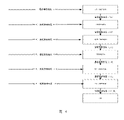
- the highest cell voltage of the battery set 7 voltage intervals: the voltage interval in which the highest cell voltage is lower than V1 (Maximum cell voltage ⁇ V1 in Figure 4), and the voltage interval in which the highest cell voltage is not lower than V1 and lower than V2 (V1 ⁇ Maximum cell voltage ⁇ V2 in Fig. 4), the highest cell voltage is not lower than V2 and lower than V3 voltage range (V2 ⁇ Maximum cell voltage ⁇ V3 in Fig.
- the highest cell voltage is not lower than V3 and The voltage range below V4 (V3 ⁇ Maximum cell voltage ⁇ V4 in Figure 4), the voltage range where the highest cell voltage is not lower than V4 and lower than V5 (V4 ⁇ Maximum cell voltage ⁇ V5 in Figure 4), the highest cell voltage The voltage range is not lower than V5 and lower than V6 (V5 ⁇ Maximum cell voltage ⁇ V6 in Figure 4), and the voltage range where the highest cell voltage is not lower than 4.2V (Maximum cell voltage ⁇ 4.2 in Figure 4).
- V1, V2, V3, V4, V5, V6 are shown in the following table:
- the charging current based on this voltage range is set to 15.6A (15.6A*SOH in Figure 4); when the battery When the current highest cell voltage of the battery is not lower than V1 and lower than the voltage range of V2 (V1 ⁇ Maximum cell voltage ⁇ V2 in Figure 4), or the current highest cell voltage of the battery rises to not low as the charging progresses In the voltage range of V1 and lower than V2 (V1 ⁇ Maximum cell voltage ⁇ V2 in Figure 4), the charging current based on this voltage range is changed to 156A (156A*SOH in Figure 4); when the current highest cell voltage of the battery When the voltage is not lower than V2 and lower than the voltage range of V3 (V2 ⁇ Maximum cell voltage ⁇ V3 in Figure 4), or the current highest cell voltage of the battery increases to not lower than V2 and lower than When the voltage range is V3 (V2 ⁇ Maximum cell voltage ⁇ V3 in Figure 4).
- the initial temperature of the battery during charging is 26°C, that is, the current temperature of the battery is 26°C, and the current highest cell voltage If it is 3.98V, then according to the initial temperature of 26°C, it is in the temperature range of [20°C, 40°C], and the set charging current should be 156A*SOH; but according to the current maximum cell voltage of 3.98V, it is not lower than 3.875 V and lower than the voltage range of 4.13V, the set charging current should be 109.2A*SOH.
- the charging current should be 109.2A*SOH, and then correct it. Assuming that the calibration value is 1.2, then the corrected charging current is 108A*SOH, and then according to the current When the battery temperature is 26°C, check the highest temperature and the highest elevator voltmeter, and the corresponding charging current is 156A*SOH. Compare the two and take the smaller value. The charging current is 108A*SOH, and then sum it with the current consumption of the high-voltage accessories. Assuming that the current consumption of the high-voltage accessory is 10A*SOH, then the current charging current required for charging the battery is 118A*SOH, and this value can be sent to the charging pile.
- the charging pile charges the battery with a charging current of 118A*SOH.
- the current available energy of the battery is 70KwH, that is, the available energy before the battery is charged is 70KwH, and the total battery capacity is 156AH
- the calculation can be obtained
- the corresponding charging current is 51A*SOH, and then the corresponding charging current is determined according to the highest cell voltage at that time. , repeat the above steps again, get the new charging current required for charging the battery again, and send the new value to the charging pile.
- the battery management system starts to control the temperature, and needs to It falls back to the [20°C, 40°C] interval.
- the charging pile will charge the battery with a new charging current, and naturally its remaining The charging time is recalculated according to the aforementioned method, but since the new charging current is still constant, the remaining charging time is still accurate, and gradually decreases according to the regularity, without frequent jumps.
- the temperature of the battery drops back to the [20°C, 40°C] range, of course, it is necessary to re-determine the charging current according to this temperature range and the current highest cell voltage, and the remaining charging time is still recalculated according to the aforementioned method. And the charging current at this time is still constant, so the remaining charging time is still accurate, and gradually decreases according to the regularity, and there will be no frequent jumps.
- An embodiment of the present disclosure further provides an apparatus for determining remaining charging time.
- FIG. 5 a block diagram of an apparatus for determining remaining charging time according to an embodiment of the present disclosure is shown, and the apparatus includes:
- determining the current charging current module 510 for determining the current charging current according to the current temperature of the battery
- determining the current remaining required charging capacity module 520 configured to determine the current remaining required charging capacity of the battery according to the current available energy of the battery and the total capacity of the battery;
- a determining remaining charging time module 530 configured to determine the remaining charging time required by the battery according to the current remaining required charging capacity and the current charging current;
- the determining the current charging current module 510 includes:
- a first determining unit 5101 configured to determine a first charging current according to the current temperature of the battery
- the second determining unit 5102 is configured to determine the second charging current according to the current cell voltage of the battery
- a comparison and correction unit 5103 configured to compare the magnitudes of the first charging current and the second charging current, take a smaller value and make corrections to form a third charging current
- the table lookup unit 5104 is used to check the maximum temperature and the maximum elevator voltmeter according to the battery temperature to obtain the fourth charging current;
- a determining charging current unit 5105 is used to compare the magnitudes of the third charging current and the fourth charging current, take the smaller value and sum it with the consumption current of the high-voltage accessory to obtain the current charging current.
- the determining the current remaining required charging capacity module 520 includes:
- a capacity calculation unit configured to obtain the current available capacity of the battery according to the current available energy and the current voltage of the battery
- a difference unit configured to determine the difference between the total capacity and the current available capacity as the current remaining required charging capacity.
- the device further includes:
- the temperature interval setting module is used to set multiple temperature intervals according to the initial temperature of the battery
- the temperature interval setting current module is used to respectively set the corresponding first charging current for each temperature interval
- the first charging current is changed to the fifth charging current current; when the lowest temperature of the battery during charging is reduced to not higher than the corresponding second preset current value, changing the first charging current to a sixth charging current;
- the first charging current is changed to the seventh charging current current; when the maximum temperature of the battery during charging is reduced to not higher than the corresponding fourth preset current value, the first charging current is changed to the eighth charging current.
- the device further includes:
- the voltage interval setting module is used to set multiple voltage intervals according to the highest cell voltage of the battery
- the voltage interval setting current module is used to respectively set the corresponding second charging current for each voltage interval
- the second charging current is changed to the ninth charging current
- the second charging current is changed to zero.
- the temperature interval setting module is further configured to set an initial temperature interval, a special temperature interval and an end temperature interval according to the initial temperature of the battery;
- the temperature interval setting current module is further configured to respectively set corresponding first charging currents for the starting temperature interval, the special temperature interval and the ending temperature interval;
- the first charging current is changed to the eleventh charging current; if the lowest temperature of the battery is low changing the first charging current to zero at a corresponding fifth preset current value;
- the first charging current is changed to the twelfth charging current; if the lowest temperature of the battery is not higher than the corresponding When the seventh preset current value is , the first charging current is changed to the thirteenth charging current;
- the first charging current is changed to the fourteenth charging current; if the maximum temperature of the battery is higher than the corresponding At the eighth preset current value, the first charging current is changed to zero.
- An embodiment of the present disclosure further provides an automobile, where the automobile includes: a vehicle controller; the vehicle controller executes the method for determining the remaining charging time described in any one of the above steps 101 to 103 .
- the method for determining the remaining charging time of the embodiment of the present disclosure comprehensively considers the factors of battery temperature and cell voltage, so that the upper limit value of the charging current under the factors of battery temperature and cell voltage will not be exceeded, and then check with the The charging current obtained from the table is taken to be smaller after comparison, and the further accurate charging current value of fast charging will not exceed the upper limit value of charging current under the factors of battery temperature and cell voltage while satisfying the charging current demand of fast charging, and charging
- the current is a constant charging current. Since the current charging current is no longer a linear change but a constant charging current while meeting the fast charging current requirement, the remaining charging time required by the battery is determined according to the current remaining required charging capacity and the current charging current.
- the accuracy is greatly improved, and as long as the current charging current remains unchanged, the remaining charging time will not change irregularly, nor will it jump frequently, allowing users to accurately Knowing the remaining charging time improves the user experience and has high practical value.
- the device embodiments described above are only illustrative, wherein the units described as separate components may or may not be physically separated, and the components displayed as units may or may not be physical units, that is, they may be located in One place, or it can be distributed over multiple network elements. Some or all of the modules may be selected according to actual needs to achieve the purpose of the solution in this embodiment. Those of ordinary skill in the art can understand and implement it without creative effort.
- Various component embodiments of the present disclosure may be implemented in hardware, or in software modules running on one or more processors, or in a combination thereof.
- a microprocessor or a digital signal processor (DSP) may be used in practice to implement some or all of the functions of some or all of the components in a computing processing device according to embodiments of the present disclosure.
- DSP digital signal processor
- the present disclosure can also be implemented as apparatus or apparatus programs (eg, computer programs and computer program products) for performing some or all of the methods described herein.
- Such a program implementing the present disclosure may be stored on a computer-readable medium, or may be in the form of one or more signals. Such signals may be downloaded from Internet sites, or provided on carrier signals, or in any other form.
- Figure 6 illustrates a computing processing device that may implement methods in accordance with the present disclosure.
- the computing processing device traditionally includes a processor 1010 and a computer program product or computer readable medium in the form of a memory 1020 .
- the memory 1020 may be electronic memory such as flash memory, EEPROM (Electrically Erasable Programmable Read Only Memory), EPROM, hard disk, or ROM.
- the memory 1020 has storage space 1030 for program code 1031 for performing any of the method steps in the above-described methods.
- the storage space 1030 for program codes may include various program codes 1031 for implementing various steps in the above methods, respectively. These program codes can be read from or written to one or more computer program products.
- These computer program products include program code carriers such as hard disks, compact disks (CDs), memory cards or floppy disks. Such computer program products are typically portable or fixed storage units as described with reference to FIG. 7 .
- the storage unit may have storage segments, storage spaces, etc. arranged similarly to the memory 1020 in the computing processing device of FIG. 6 .
- the program code may, for example, be compressed in a suitable form.
- the storage unit includes computer readable code 1031', ie code readable by a processor such as 1010, for example, which, when executed by a computing processing device, causes the computing processing device to perform any of the methods described above. of the various steps.
Landscapes
- Engineering & Computer Science (AREA)
- Physics & Mathematics (AREA)
- General Physics & Mathematics (AREA)
- Power Engineering (AREA)
- Chemical & Material Sciences (AREA)
- Manufacturing & Machinery (AREA)
- Electrochemistry (AREA)
- General Chemical & Material Sciences (AREA)
- Chemical Kinetics & Catalysis (AREA)
- Combustion & Propulsion (AREA)
- Mechanical Engineering (AREA)
- Charge And Discharge Circuits For Batteries Or The Like (AREA)
- Secondary Cells (AREA)
- Electric Propulsion And Braking For Vehicles (AREA)
Abstract
Description
| V 1 | 3.2V |
| V2 | 3.875V |
| V3 | 4.13V |
| V 4 | 4.14V |
| V5 | 4.15V |
| V6 | 4.16V |
Claims (13)
- 一种确定剩余充电时间的方法,其特征在于,所述方法包括:根据电池的当前温度、当前单体电压确定当前充电电流;根据所述电池的当前可用能量和所述电池的总容量,确定所述电池的当前剩余所需充电容量;根据所述当前剩余所需充电容量和所述当前充电电流,确定所述电池所需的剩余充电时间;其中,根据电池的当前温度、当前单体电压确定当前充电电流,包括:根据所述电池的当前温度确定第一充电电流;根据电池的当前单体电压确定第二充电电流;比较所述第一充电电流和所述第二充电电流的大小,取较小值并做修正,形成第三充电电流;根据电池温度查最高温度及最高电梯电压表得到第四充电电流;比较所述第三充电电流和所述第四充电电流的大小,取较小值后与高压附件消耗电流求和,得到所述当前充电电流。
- 根据权利要求1所述的方法,其特征在于,根据所述电池的当前可用能量和所述电池的总容量,确定所述电池的当前剩余所需充电容量,包括:根据所述当前可用能量和所述电池的当前单体电压,运算得到所述电池的当前可用容量;将所述总容量与所述当前可用容量之间的差值确定为所述当前剩余所需充电容量。
- 根据权利要求1所述的方法,其特征在于,在根据所述电池的当前温度确定第一充电电流之前,还包括:按照电池初始温度,设置多个温度区间;为每个温度区间分别设置相应的第一充电电流;其中,对于低于预设温度阈值的每个温度区间,在充电期间电池的当前最低温度升高至不低于对应的第一预设电流值时,将所述第一充电电流更改为第五充电电流;在充电期间电池的当前最低温度降低至不高于对应的第二 预设电流值时,将所述第一充电电流更改为第六充电电流;其中,对于高于预设温度阈值的每个温度区间,在充电期间电池的当前最高温度升高至不低于对应的第三预设电流值时,将所述第一充电电流更改为第七充电电流;在充电期间电池的当前最高温度降低至不高于对应的第四预设电流值时,将所述第一充电电流更改为第八充电电流。
- 根据权利要求1所述的方法,其特征在于,在根据电池的当前单体电压确定第二充电电流之前,还包括:按照电池的最高单体电压,设置多个电压区间;为每个电压区间分别设置相应的第二充电电流;其中,在充电期间电池的当前最高单体电压低于对应的第一预设电压值时,将所述第二充电电流更改为第九充电电流;在充电期间电池的当前最高单体电压不低于对应的第一预设电压值,且同时低于第二预设电压值时,将所述第二充电电流更改为第十充电电流;在所述电池的当前最高单体电压不低于预设电压阈值时,将所述第二充电电流更改为零。
- 根据权利要求1所述的方法,其特征在于,还包括:按照电池初始温度,设置起始温度区间、特殊温度区间和终止温度区间;为所述起始温度区间、所述特殊温度区间和所述终止温度区间分别设置相应的第一充电电流;其中,在所述起始温度区间内,若电池的当前最低温度不低于对应的第五预设电流值时,将所述第一充电电流更改为第十一充电电流;若电池的当前最低温度低于对应的第五预设电流值时,将所述第一充电电流更改为零;在所述特殊温度区间内,若电池的当前最高温度不低于对应的第六预设电流值时,将所述第一充电电流更改为第十二充电电流;若电池的当前最低温度不高于对应的第七预设电流值时,将所述第一充电电流更改为第十三充电电流;在所述终止温度区间内,若电池的当前最高温度不高于对应的第八预设电流值时,将所述第一充电电流更改为第十四充电电流;若电池的当前最高 温度高于对应的第八预设电流值时,将所述第一充电电流更改为零。
- 一种确定剩余充电时间的装置,其特征在于,所述装置包括:确定当前充电电流模块,用于根据电池的当前温度、当前单体电压确定当前充电电流;确定当前剩余所需充电容量模块,用于根据所述电池的当前可用能量和所述电池的总容量,确定所述电池的当前剩余所需充电容量;确定剩余充电时间模块,用于根据所述当前剩余所需充电容量和所述当前充电电流,确定所述电池所需的剩余充电时间;其中,所述确定当前充电电流模块包括:第一确定单元,用于根据所述电池的当前温度确定第一充电电流;第二确定单元,用于根据电池的当前单体电压确定第二充电电流;比较修正单元,用于比较所述第一充电电流和所述第二充电电流的大小,取较小值并做修正,形成第三充电电流;查表单元,用于根据电池温度查最高温度及最高电梯电压表得到第四充电电流;确定充电电流单元,用于比较所述第三充电电流和所述第四充电电流的大小,取较小值后与高压附件消耗电流求和,得到所述当前充电电流。
- 根据权利要求6所述的装置,其特征在于,所述确定当前剩余所需充电容量模块包括:运算容量单元,用于根据所述当前可用能量和所述电池的当前单体电压,运算得到所述电池的当前可用容量;差值单元,用于将所述总容量与所述当前可用容量之间的差值确定为所述当前剩余所需充电容量。
- 根据权利要求6所述的装置,其特征在于,所述装置还包括:温度区间设置模块,用于按照电池初始温度,设置多个温度区间;温度区间设置电流模块,用于为每个温度区间分别设置相应的第一充电电流;其中,对于低于预设温度阈值的每个温度区间,在充电期间电池的当前 最低温度升高至不低于对应的第一预设电流值时,将所述第一充电电流更改为第五充电电流;在充电期间电池的当前最低温度降低至不高于对应的第二预设电流值时,将所述第一充电电流更改为第六充电电流;其中,对于高于预设温度阈值的每个温度区间,在充电期间电池的当前最高温度升高至不低于对应的第三预设电流值时,将所述第一充电电流更改为第七充电电流;在充电期间电池的当前最高温度降低至不高于对应的第四预设电流值时,将所述第一充电电流更改为第八充电电流。
- 根据权利要求6所述的装置,其特征在于,所述装置还包括:电压区间设置模块,用于按照电池的最高单体电压,设置多个电压区间;电压区间设置电流模块,用于为每个电压区间分别设置相应的第二充电电流;其中,在充电期间电池的当前最高单体电压低于对应的第一预设电压值时,将所述第二充电电流更改为第九充电电流;在充电期间电池的当前最高单体电压不低于对应的第一预设电压值,且同时低于第二预设电压值时,将所述第二充电电流更改为第十充电电流;在所述电池的当前最高单体电压不低于预设电压阈值时,将所述第二充电电流更改为零。
- 一种汽车,其特征在于,所述汽车包括:整车控制器;所述整车控制器执行如权利要求1-5任一所述的确定剩余充电时间的方法。
- 一种计算处理设备,其特征在于,包括:存储器,其中存储有计算机可读代码;以及一个或多个处理器,当所述计算机可读代码被所述一个或多个处理器执行时,所述计算处理设备执行如权利要求1-5任一所述的确定剩余充电时间的方法。
- 一种计算机程序,包括计算机可读代码,当所述计算机可读代码在计算处理设备上运行时,导致所述计算处理设备执行根据权利要求1-5任一所述的确定剩余充电时间的方法。
- 一种计算机可读介质,其中存储了如权利要求12所述的计算机程序。
Priority Applications (3)
| Application Number | Priority Date | Filing Date | Title |
|---|---|---|---|
| KR1020237012255A KR102730104B1 (ko) | 2020-10-13 | 2021-09-28 | 잔여 충전 시간 결정 방법, 장치 및 자동차 |
| JP2023521517A JP2023545276A (ja) | 2020-10-13 | 2021-09-28 | 余剰充電時間を決定する方法、装置及び自動車 |
| EP21879252.1A EP4231025A4 (en) | 2020-10-13 | 2021-09-28 | METHOD AND DEVICE FOR DETERMINING REMAINING CHARGING TIME AND VEHICLE |
Applications Claiming Priority (2)
| Application Number | Priority Date | Filing Date | Title |
|---|---|---|---|
| CN202011091613.2A CN112526346B (zh) | 2020-10-13 | 2020-10-13 | 一种确定剩余充电时间的方法、装置以及一种汽车 |
| CN202011091613.2 | 2020-10-13 |
Publications (1)
| Publication Number | Publication Date |
|---|---|
| WO2022078206A1 true WO2022078206A1 (zh) | 2022-04-21 |
Family
ID=74979116
Family Applications (1)
| Application Number | Title | Priority Date | Filing Date |
|---|---|---|---|
| PCT/CN2021/121227 Ceased WO2022078206A1 (zh) | 2020-10-13 | 2021-09-28 | 一种确定剩余充电时间的方法、装置以及一种汽车 |
Country Status (5)
| Country | Link |
|---|---|
| EP (1) | EP4231025A4 (zh) |
| JP (1) | JP2023545276A (zh) |
| KR (1) | KR102730104B1 (zh) |
| CN (1) | CN112526346B (zh) |
| WO (1) | WO2022078206A1 (zh) |
Cited By (1)
| Publication number | Priority date | Publication date | Assignee | Title |
|---|---|---|---|---|
| CN115308601A (zh) * | 2022-06-30 | 2022-11-08 | 重庆长安新能源汽车科技有限公司 | 一种动力电池剩余充电时间估算方法 |
Families Citing this family (9)
| Publication number | Priority date | Publication date | Assignee | Title |
|---|---|---|---|---|
| CN112383099A (zh) * | 2020-10-09 | 2021-02-19 | 长城汽车股份有限公司 | 一种确定直流充电电流的方法、装置以及一种汽车 |
| CN112526346B (zh) * | 2020-10-13 | 2024-10-29 | 长城汽车股份有限公司 | 一种确定剩余充电时间的方法、装置以及一种汽车 |
| CN113147507B (zh) * | 2021-04-25 | 2022-03-25 | 北京新能源汽车股份有限公司 | 剩余充电时长的估算方法、装置及电动汽车 |
| CN113985291B (zh) * | 2021-10-31 | 2023-12-05 | 三一汽车制造有限公司 | 一种剩余充电时间预估方法、装置及车辆控制设备 |
| CN115825781B (zh) * | 2022-01-19 | 2024-02-20 | 宁德时代新能源科技股份有限公司 | 充电时间确定方法及bms、电池、电能设备 |
| KR102837957B1 (ko) | 2022-01-19 | 2025-07-23 | 컨템포러리 엠퍼렉스 테크놀로지 (홍콩) 리미티드 | 충전시간 결정 방법 및 bms, 배터리, 전기에너지 장비 |
| CN114889493B (zh) * | 2022-06-28 | 2024-08-06 | 重庆长安新能源汽车科技有限公司 | 电动汽车直流快充时间预测方法、系统、车辆及存储介质 |
| CN115648998B (zh) * | 2022-10-20 | 2024-09-10 | 湖北亿纬动力有限公司 | 电池充电时长确定方法、确定装置以及电池管理系统 |
| CN115642327A (zh) * | 2022-10-28 | 2023-01-24 | 奇瑞新能源汽车股份有限公司 | 一种电动汽车高温快充控制方法及汽车 |
Citations (10)
| Publication number | Priority date | Publication date | Assignee | Title |
|---|---|---|---|---|
| JPH11206024A (ja) * | 1998-01-19 | 1999-07-30 | Matsushita Electric Ind Co Ltd | 二次電池の充電完了時間予測方法、二次電池の充電完了時間予測装置、電池パック及び電子機器 |
| JP2006262605A (ja) * | 2005-03-16 | 2006-09-28 | Seiko Epson Corp | 充電残り時間算出装置 |
| CN102707234A (zh) * | 2012-05-04 | 2012-10-03 | 惠州市亿能电子有限公司 | 电池组剩余充电时间估算方法 |
| CN105467321A (zh) * | 2014-05-29 | 2016-04-06 | 比亚迪股份有限公司 | 电池的充电剩余时间的计算方法和电池系统 |
| CN106876807A (zh) * | 2017-03-02 | 2017-06-20 | 惠州市亿能电子有限公司 | 一种估算充电剩余时间的方法 |
| CN108199433A (zh) * | 2018-01-10 | 2018-06-22 | 深圳天珑无线科技有限公司 | 电池充电时间的计算方法、终端和计算机可读存储介质 |
| CN109245229A (zh) * | 2018-10-26 | 2019-01-18 | 东软睿驰汽车技术(沈阳)有限公司 | 一种电池剩余充电时间的估算方法、装置 |
| CN109808546A (zh) * | 2019-02-15 | 2019-05-28 | 爱驰汽车有限公司 | 提供充电剩余时间的方法、装置、电子设备、存储介质 |
| CN111055722A (zh) * | 2019-12-20 | 2020-04-24 | 华为技术有限公司 | 一种预估充电时间的方法,装置及存储介质 |
| CN112526346A (zh) * | 2020-10-13 | 2021-03-19 | 长城汽车股份有限公司 | 一种确定剩余充电时间的方法、装置以及一种汽车 |
Family Cites Families (16)
| Publication number | Priority date | Publication date | Assignee | Title |
|---|---|---|---|---|
| JPH0898426A (ja) * | 1994-09-21 | 1996-04-12 | Toyota Motor Corp | バッテリの充電方法 |
| JP3983681B2 (ja) * | 2003-01-14 | 2007-09-26 | 株式会社マキタ | 充電装置 |
| JP4375458B2 (ja) * | 2007-08-01 | 2009-12-02 | 株式会社デンソー | 2次電池の充電状態推定装置及び充電制御システム |
| US9252624B2 (en) * | 2011-06-10 | 2016-02-02 | Hitachi Automotive Systems, Ltd. | Battery control device and battery system |
| JP6767198B2 (ja) * | 2015-11-30 | 2020-10-14 | 株式会社マキタ | バッテリ装置及び充電装置 |
| JP6832516B2 (ja) * | 2016-01-21 | 2021-02-24 | パナソニックIpマネジメント株式会社 | 充電回路及び電子機器 |
| CN106208213A (zh) * | 2016-08-04 | 2016-12-07 | 广东欧珀移动通信有限公司 | 一种pid调节充电电流的方法及终端 |
| CN110945738B (zh) * | 2017-07-31 | 2023-04-28 | 日产自动车株式会社 | 充电时间运算方法和充电控制装置 |
| KR102468385B1 (ko) * | 2018-01-05 | 2022-11-18 | 현대자동차주식회사 | 친환경 차량 배터리의 충전시간 예측 방법 |
| CN112055913B (zh) * | 2018-05-31 | 2024-08-09 | 本田技研工业株式会社 | 充电控制装置、输送设备以及计算机可读存储介质 |
| JP7062534B2 (ja) * | 2018-06-26 | 2022-05-06 | 株式会社マキタ | 充電式クリーナ |
| CN111196179B (zh) * | 2018-11-16 | 2021-07-20 | 宝沃汽车(中国)有限公司 | 电池剩余充电时间的估算方法、估算装置及车辆 |
| CN111257752B (zh) * | 2018-11-30 | 2021-02-26 | 宁德时代新能源科技股份有限公司 | 剩余充电时间估算方法、装置、系统和存储介质 |
| KR102811048B1 (ko) * | 2019-03-08 | 2025-05-21 | 삼성전자주식회사 | 배터리 장치의 충전 상태를 결정하기 위한 전자 장치 및 상기 전자 장치의 동작 방법 |
| CN110562097A (zh) * | 2019-09-20 | 2019-12-13 | 芜湖宏景电子股份有限公司 | 一种新能源汽车充电剩余时间估算方法 |
| CN110829543B (zh) * | 2019-11-26 | 2021-05-18 | 桑顿新能源科技有限公司 | 充电电流动态调整方法、装置和新能源汽车 |
-
2020
- 2020-10-13 CN CN202011091613.2A patent/CN112526346B/zh active Active
-
2021
- 2021-09-28 WO PCT/CN2021/121227 patent/WO2022078206A1/zh not_active Ceased
- 2021-09-28 KR KR1020237012255A patent/KR102730104B1/ko active Active
- 2021-09-28 JP JP2023521517A patent/JP2023545276A/ja active Pending
- 2021-09-28 EP EP21879252.1A patent/EP4231025A4/en active Pending
Patent Citations (10)
| Publication number | Priority date | Publication date | Assignee | Title |
|---|---|---|---|---|
| JPH11206024A (ja) * | 1998-01-19 | 1999-07-30 | Matsushita Electric Ind Co Ltd | 二次電池の充電完了時間予測方法、二次電池の充電完了時間予測装置、電池パック及び電子機器 |
| JP2006262605A (ja) * | 2005-03-16 | 2006-09-28 | Seiko Epson Corp | 充電残り時間算出装置 |
| CN102707234A (zh) * | 2012-05-04 | 2012-10-03 | 惠州市亿能电子有限公司 | 电池组剩余充电时间估算方法 |
| CN105467321A (zh) * | 2014-05-29 | 2016-04-06 | 比亚迪股份有限公司 | 电池的充电剩余时间的计算方法和电池系统 |
| CN106876807A (zh) * | 2017-03-02 | 2017-06-20 | 惠州市亿能电子有限公司 | 一种估算充电剩余时间的方法 |
| CN108199433A (zh) * | 2018-01-10 | 2018-06-22 | 深圳天珑无线科技有限公司 | 电池充电时间的计算方法、终端和计算机可读存储介质 |
| CN109245229A (zh) * | 2018-10-26 | 2019-01-18 | 东软睿驰汽车技术(沈阳)有限公司 | 一种电池剩余充电时间的估算方法、装置 |
| CN109808546A (zh) * | 2019-02-15 | 2019-05-28 | 爱驰汽车有限公司 | 提供充电剩余时间的方法、装置、电子设备、存储介质 |
| CN111055722A (zh) * | 2019-12-20 | 2020-04-24 | 华为技术有限公司 | 一种预估充电时间的方法,装置及存储介质 |
| CN112526346A (zh) * | 2020-10-13 | 2021-03-19 | 长城汽车股份有限公司 | 一种确定剩余充电时间的方法、装置以及一种汽车 |
Non-Patent Citations (1)
| Title |
|---|
| See also references of EP4231025A4 * |
Cited By (1)
| Publication number | Priority date | Publication date | Assignee | Title |
|---|---|---|---|---|
| CN115308601A (zh) * | 2022-06-30 | 2022-11-08 | 重庆长安新能源汽车科技有限公司 | 一种动力电池剩余充电时间估算方法 |
Also Published As
| Publication number | Publication date |
|---|---|
| KR102730104B1 (ko) | 2024-11-15 |
| JP2023545276A (ja) | 2023-10-27 |
| CN112526346B (zh) | 2024-10-29 |
| CN112526346A (zh) | 2021-03-19 |
| EP4231025A1 (en) | 2023-08-23 |
| EP4231025A4 (en) | 2024-05-01 |
| KR20230066088A (ko) | 2023-05-12 |
Similar Documents
| Publication | Publication Date | Title |
|---|---|---|
| EP4231025A1 (en) | Method and apparatus for determining remaining charging time, and vehicle | |
| WO2022073451A1 (zh) | 一种确定直流充电电流的方法、装置以及一种汽车 | |
| EP4019321B1 (en) | Battery managing method and device, and vehicle | |
| EP2703829B1 (en) | Device and method for estimating the degradation of battery capacity | |
| JP5493657B2 (ja) | 蓄電池装置並びに蓄電池の電池状態評価装置及び方法 | |
| CN102124354B (zh) | 使用电池电压行为估计电池电阻特性的装置及方法 | |
| CN102119338B (zh) | 基于电池电压变化模式估计电池健康状态的方法及装置 | |
| KR100970343B1 (ko) | 충전상태를 이용한 전지 평활화 시스템 및 방법 | |
| TWI419390B (zh) | 電池裝置之剩餘容量與剩餘使用時間的估算方法 | |
| CN110753849B (zh) | 电池容量估计设备及方法以及具有电池容量估计设备的电池管理设备及方法 | |
| US20120049802A1 (en) | Monitoring a rechargeable battery with multiple parameter update rates | |
| CN1988314A (zh) | 用于补偿电池充电状态的方法和使用该方法的电池管理系统 | |
| KR20120120889A (ko) | 배터리 용량 퇴화 추정 장치 및 방법 | |
| CN114114054A (zh) | 能够监测电池状况的电池状况监测装置 | |
| WO2019230131A1 (ja) | 充電制御装置、輸送機器、及びプログラム | |
| CN105814770B (zh) | 用于可再充电电池单体的快速充电的方法和系统 | |
| CN117491892A (zh) | 车辆及其动力电池健康状态的估算方法、装置及存储介质 | |
| KR20220128023A (ko) | 실시간 soh 정보를 이용한 배터리 충전제어 방법 및 장치 | |
| KR102702135B1 (ko) | 배터리 충전 방법 및 장치 | |
| CN116879787A (zh) | 用于对电池荷电状态进行初始化的方法、装置及电动设备 | |
| US20250341583A1 (en) | Battery full charge capacity estimation method, battery full charge capacity estimation device, and full charge capacity estimation program | |
| JP2020156148A (ja) | 二次電池の制御装置 | |
| CN120254626A (zh) | 一种提高多支路并联电池系统充电剩余时间精度的方法 | |
| CN121150244A (zh) | 充电效率调节方法、控制器和储能装置 | |
| CN119199598A (zh) | 一种基于优选法摸索电池极限电流的方法 |
Legal Events
| Date | Code | Title | Description |
|---|---|---|---|
| 121 | Ep: the epo has been informed by wipo that ep was designated in this application |
Ref document number: 21879252 Country of ref document: EP Kind code of ref document: A1 |
|
| ENP | Entry into the national phase |
Ref document number: 2023521517 Country of ref document: JP Kind code of ref document: A |
|
| ENP | Entry into the national phase |
Ref document number: 20237012255 Country of ref document: KR Kind code of ref document: A |
|
| NENP | Non-entry into the national phase |
Ref country code: DE |
|
| ENP | Entry into the national phase |
Ref document number: 2021879252 Country of ref document: EP Effective date: 20230515 |