WO2022079987A1 - 高強度冷延鋼板,高強度めっき鋼板,高強度冷延鋼板の製造方法,高強度めっき鋼板の製造方法,及び自動車部品 - Google Patents
高強度冷延鋼板,高強度めっき鋼板,高強度冷延鋼板の製造方法,高強度めっき鋼板の製造方法,及び自動車部品 Download PDFInfo
- Publication number
- WO2022079987A1 WO2022079987A1 PCT/JP2021/029205 JP2021029205W WO2022079987A1 WO 2022079987 A1 WO2022079987 A1 WO 2022079987A1 JP 2021029205 W JP2021029205 W JP 2021029205W WO 2022079987 A1 WO2022079987 A1 WO 2022079987A1
- Authority
- WO
- WIPO (PCT)
- Prior art keywords
- less
- ferrite
- rolled
- cold
- strength
- Prior art date
- Legal status (The legal status is an assumption and is not a legal conclusion. Google has not performed a legal analysis and makes no representation as to the accuracy of the status listed.)
- Ceased
Links
Classifications
-
- C—CHEMISTRY; METALLURGY
- C21—METALLURGY OF IRON
- C21D—MODIFYING THE PHYSICAL STRUCTURE OF FERROUS METALS; GENERAL DEVICES FOR HEAT TREATMENT OF FERROUS OR NON-FERROUS METALS OR ALLOYS; MAKING METAL MALLEABLE, e.g. BY DECARBURISATION OR TEMPERING
- C21D8/00—Modifying the physical properties of ferrous metals or ferrous alloys by deformation combined with, or followed by, heat treatment
- C21D8/02—Modifying the physical properties of ferrous metals or ferrous alloys by deformation combined with, or followed by, heat treatment during manufacturing of plates or strips
- C21D8/0247—Modifying the physical properties of ferrous metals or ferrous alloys by deformation combined with, or followed by, heat treatment during manufacturing of plates or strips characterised by the heat treatment
- C21D8/0273—Final recrystallisation annealing
-
- C—CHEMISTRY; METALLURGY
- C21—METALLURGY OF IRON
- C21D—MODIFYING THE PHYSICAL STRUCTURE OF FERROUS METALS; GENERAL DEVICES FOR HEAT TREATMENT OF FERROUS OR NON-FERROUS METALS OR ALLOYS; MAKING METAL MALLEABLE, e.g. BY DECARBURISATION OR TEMPERING
- C21D8/00—Modifying the physical properties of ferrous metals or ferrous alloys by deformation combined with, or followed by, heat treatment
- C21D8/02—Modifying the physical properties of ferrous metals or ferrous alloys by deformation combined with, or followed by, heat treatment during manufacturing of plates or strips
- C21D8/0247—Modifying the physical properties of ferrous metals or ferrous alloys by deformation combined with, or followed by, heat treatment during manufacturing of plates or strips characterised by the heat treatment
- C21D8/0268—Modifying the physical properties of ferrous metals or ferrous alloys by deformation combined with, or followed by, heat treatment during manufacturing of plates or strips characterised by the heat treatment between cold rolling steps
-
- C—CHEMISTRY; METALLURGY
- C22—METALLURGY; FERROUS OR NON-FERROUS ALLOYS; TREATMENT OF ALLOYS OR NON-FERROUS METALS
- C22C—ALLOYS
- C22C38/00—Ferrous alloys, e.g. steel alloys
- C22C38/04—Ferrous alloys, e.g. steel alloys containing manganese
-
- B—PERFORMING OPERATIONS; TRANSPORTING
- B32—LAYERED PRODUCTS
- B32B—LAYERED PRODUCTS, i.e. PRODUCTS BUILT-UP OF STRATA OF FLAT OR NON-FLAT, e.g. CELLULAR OR HONEYCOMB, FORM
- B32B15/00—Layered products comprising a layer of metal
- B32B15/01—Layered products comprising a layer of metal all layers being exclusively metallic
- B32B15/013—Layered products comprising a layer of metal all layers being exclusively metallic one layer being formed of an iron alloy or steel, another layer being formed of a metal other than iron or aluminium
-
- C—CHEMISTRY; METALLURGY
- C21—METALLURGY OF IRON
- C21D—MODIFYING THE PHYSICAL STRUCTURE OF FERROUS METALS; GENERAL DEVICES FOR HEAT TREATMENT OF FERROUS OR NON-FERROUS METALS OR ALLOYS; MAKING METAL MALLEABLE, e.g. BY DECARBURISATION OR TEMPERING
- C21D1/00—General methods or devices for heat treatment, e.g. annealing, hardening, quenching or tempering
- C21D1/18—Hardening; Quenching with or without subsequent tempering
-
- C—CHEMISTRY; METALLURGY
- C21—METALLURGY OF IRON
- C21D—MODIFYING THE PHYSICAL STRUCTURE OF FERROUS METALS; GENERAL DEVICES FOR HEAT TREATMENT OF FERROUS OR NON-FERROUS METALS OR ALLOYS; MAKING METAL MALLEABLE, e.g. BY DECARBURISATION OR TEMPERING
- C21D1/00—General methods or devices for heat treatment, e.g. annealing, hardening, quenching or tempering
- C21D1/18—Hardening; Quenching with or without subsequent tempering
- C21D1/185—Hardening; Quenching with or without subsequent tempering from an intercritical temperature
-
- C—CHEMISTRY; METALLURGY
- C21—METALLURGY OF IRON
- C21D—MODIFYING THE PHYSICAL STRUCTURE OF FERROUS METALS; GENERAL DEVICES FOR HEAT TREATMENT OF FERROUS OR NON-FERROUS METALS OR ALLOYS; MAKING METAL MALLEABLE, e.g. BY DECARBURISATION OR TEMPERING
- C21D1/00—General methods or devices for heat treatment, e.g. annealing, hardening, quenching or tempering
- C21D1/18—Hardening; Quenching with or without subsequent tempering
- C21D1/19—Hardening; Quenching with or without subsequent tempering by interrupted quenching
-
- C—CHEMISTRY; METALLURGY
- C21—METALLURGY OF IRON
- C21D—MODIFYING THE PHYSICAL STRUCTURE OF FERROUS METALS; GENERAL DEVICES FOR HEAT TREATMENT OF FERROUS OR NON-FERROUS METALS OR ALLOYS; MAKING METAL MALLEABLE, e.g. BY DECARBURISATION OR TEMPERING
- C21D1/00—General methods or devices for heat treatment, e.g. annealing, hardening, quenching or tempering
- C21D1/18—Hardening; Quenching with or without subsequent tempering
- C21D1/19—Hardening; Quenching with or without subsequent tempering by interrupted quenching
- C21D1/20—Isothermal quenching, e.g. bainitic hardening
-
- C—CHEMISTRY; METALLURGY
- C21—METALLURGY OF IRON
- C21D—MODIFYING THE PHYSICAL STRUCTURE OF FERROUS METALS; GENERAL DEVICES FOR HEAT TREATMENT OF FERROUS OR NON-FERROUS METALS OR ALLOYS; MAKING METAL MALLEABLE, e.g. BY DECARBURISATION OR TEMPERING
- C21D1/00—General methods or devices for heat treatment, e.g. annealing, hardening, quenching or tempering
- C21D1/18—Hardening; Quenching with or without subsequent tempering
- C21D1/25—Hardening, combined with annealing between 300 degrees Celsius and 600 degrees Celsius, i.e. heat refining ("Vergüten")
-
- C—CHEMISTRY; METALLURGY
- C21—METALLURGY OF IRON
- C21D—MODIFYING THE PHYSICAL STRUCTURE OF FERROUS METALS; GENERAL DEVICES FOR HEAT TREATMENT OF FERROUS OR NON-FERROUS METALS OR ALLOYS; MAKING METAL MALLEABLE, e.g. BY DECARBURISATION OR TEMPERING
- C21D6/00—Heat treatment of ferrous alloys
- C21D6/005—Heat treatment of ferrous alloys containing Mn
-
- C—CHEMISTRY; METALLURGY
- C21—METALLURGY OF IRON
- C21D—MODIFYING THE PHYSICAL STRUCTURE OF FERROUS METALS; GENERAL DEVICES FOR HEAT TREATMENT OF FERROUS OR NON-FERROUS METALS OR ALLOYS; MAKING METAL MALLEABLE, e.g. BY DECARBURISATION OR TEMPERING
- C21D8/00—Modifying the physical properties of ferrous metals or ferrous alloys by deformation combined with, or followed by, heat treatment
- C21D8/02—Modifying the physical properties of ferrous metals or ferrous alloys by deformation combined with, or followed by, heat treatment during manufacturing of plates or strips
-
- C—CHEMISTRY; METALLURGY
- C21—METALLURGY OF IRON
- C21D—MODIFYING THE PHYSICAL STRUCTURE OF FERROUS METALS; GENERAL DEVICES FOR HEAT TREATMENT OF FERROUS OR NON-FERROUS METALS OR ALLOYS; MAKING METAL MALLEABLE, e.g. BY DECARBURISATION OR TEMPERING
- C21D8/00—Modifying the physical properties of ferrous metals or ferrous alloys by deformation combined with, or followed by, heat treatment
- C21D8/02—Modifying the physical properties of ferrous metals or ferrous alloys by deformation combined with, or followed by, heat treatment during manufacturing of plates or strips
- C21D8/0221—Modifying the physical properties of ferrous metals or ferrous alloys by deformation combined with, or followed by, heat treatment during manufacturing of plates or strips characterised by the working steps
- C21D8/0226—Hot rolling
-
- C—CHEMISTRY; METALLURGY
- C21—METALLURGY OF IRON
- C21D—MODIFYING THE PHYSICAL STRUCTURE OF FERROUS METALS; GENERAL DEVICES FOR HEAT TREATMENT OF FERROUS OR NON-FERROUS METALS OR ALLOYS; MAKING METAL MALLEABLE, e.g. BY DECARBURISATION OR TEMPERING
- C21D8/00—Modifying the physical properties of ferrous metals or ferrous alloys by deformation combined with, or followed by, heat treatment
- C21D8/02—Modifying the physical properties of ferrous metals or ferrous alloys by deformation combined with, or followed by, heat treatment during manufacturing of plates or strips
- C21D8/0221—Modifying the physical properties of ferrous metals or ferrous alloys by deformation combined with, or followed by, heat treatment during manufacturing of plates or strips characterised by the working steps
- C21D8/0236—Cold rolling
-
- C—CHEMISTRY; METALLURGY
- C21—METALLURGY OF IRON
- C21D—MODIFYING THE PHYSICAL STRUCTURE OF FERROUS METALS; GENERAL DEVICES FOR HEAT TREATMENT OF FERROUS OR NON-FERROUS METALS OR ALLOYS; MAKING METAL MALLEABLE, e.g. BY DECARBURISATION OR TEMPERING
- C21D8/00—Modifying the physical properties of ferrous metals or ferrous alloys by deformation combined with, or followed by, heat treatment
- C21D8/02—Modifying the physical properties of ferrous metals or ferrous alloys by deformation combined with, or followed by, heat treatment during manufacturing of plates or strips
- C21D8/0247—Modifying the physical properties of ferrous metals or ferrous alloys by deformation combined with, or followed by, heat treatment during manufacturing of plates or strips characterised by the heat treatment
-
- C—CHEMISTRY; METALLURGY
- C21—METALLURGY OF IRON
- C21D—MODIFYING THE PHYSICAL STRUCTURE OF FERROUS METALS; GENERAL DEVICES FOR HEAT TREATMENT OF FERROUS OR NON-FERROUS METALS OR ALLOYS; MAKING METAL MALLEABLE, e.g. BY DECARBURISATION OR TEMPERING
- C21D8/00—Modifying the physical properties of ferrous metals or ferrous alloys by deformation combined with, or followed by, heat treatment
- C21D8/02—Modifying the physical properties of ferrous metals or ferrous alloys by deformation combined with, or followed by, heat treatment during manufacturing of plates or strips
- C21D8/0247—Modifying the physical properties of ferrous metals or ferrous alloys by deformation combined with, or followed by, heat treatment during manufacturing of plates or strips characterised by the heat treatment
- C21D8/0263—Modifying the physical properties of ferrous metals or ferrous alloys by deformation combined with, or followed by, heat treatment during manufacturing of plates or strips characterised by the heat treatment following hot rolling
-
- C—CHEMISTRY; METALLURGY
- C21—METALLURGY OF IRON
- C21D—MODIFYING THE PHYSICAL STRUCTURE OF FERROUS METALS; GENERAL DEVICES FOR HEAT TREATMENT OF FERROUS OR NON-FERROUS METALS OR ALLOYS; MAKING METAL MALLEABLE, e.g. BY DECARBURISATION OR TEMPERING
- C21D8/00—Modifying the physical properties of ferrous metals or ferrous alloys by deformation combined with, or followed by, heat treatment
- C21D8/02—Modifying the physical properties of ferrous metals or ferrous alloys by deformation combined with, or followed by, heat treatment during manufacturing of plates or strips
- C21D8/0278—Modifying the physical properties of ferrous metals or ferrous alloys by deformation combined with, or followed by, heat treatment during manufacturing of plates or strips involving a particular surface treatment
-
- C—CHEMISTRY; METALLURGY
- C21—METALLURGY OF IRON
- C21D—MODIFYING THE PHYSICAL STRUCTURE OF FERROUS METALS; GENERAL DEVICES FOR HEAT TREATMENT OF FERROUS OR NON-FERROUS METALS OR ALLOYS; MAKING METAL MALLEABLE, e.g. BY DECARBURISATION OR TEMPERING
- C21D9/00—Heat treatment, e.g. annealing, hardening, quenching or tempering, adapted for particular articles; Furnaces therefor
- C21D9/46—Heat treatment, e.g. annealing, hardening, quenching or tempering, adapted for particular articles; Furnaces therefor for sheet metals
-
- C—CHEMISTRY; METALLURGY
- C22—METALLURGY; FERROUS OR NON-FERROUS ALLOYS; TREATMENT OF ALLOYS OR NON-FERROUS METALS
- C22C—ALLOYS
- C22C18/00—Alloys based on zinc
-
- C—CHEMISTRY; METALLURGY
- C22—METALLURGY; FERROUS OR NON-FERROUS ALLOYS; TREATMENT OF ALLOYS OR NON-FERROUS METALS
- C22C—ALLOYS
- C22C18/00—Alloys based on zinc
- C22C18/04—Alloys based on zinc with aluminium as the next major constituent
-
- C—CHEMISTRY; METALLURGY
- C22—METALLURGY; FERROUS OR NON-FERROUS ALLOYS; TREATMENT OF ALLOYS OR NON-FERROUS METALS
- C22C—ALLOYS
- C22C38/00—Ferrous alloys, e.g. steel alloys
- C22C38/001—Ferrous alloys, e.g. steel alloys containing N
-
- C—CHEMISTRY; METALLURGY
- C22—METALLURGY; FERROUS OR NON-FERROUS ALLOYS; TREATMENT OF ALLOYS OR NON-FERROUS METALS
- C22C—ALLOYS
- C22C38/00—Ferrous alloys, e.g. steel alloys
- C22C38/002—Ferrous alloys, e.g. steel alloys containing In, Mg, or other elements not provided for in one single group C22C38/001 - C22C38/60
-
- C—CHEMISTRY; METALLURGY
- C22—METALLURGY; FERROUS OR NON-FERROUS ALLOYS; TREATMENT OF ALLOYS OR NON-FERROUS METALS
- C22C—ALLOYS
- C22C38/00—Ferrous alloys, e.g. steel alloys
- C22C38/005—Ferrous alloys, e.g. steel alloys containing rare earths, i.e. Sc, Y, Lanthanides
-
- C—CHEMISTRY; METALLURGY
- C22—METALLURGY; FERROUS OR NON-FERROUS ALLOYS; TREATMENT OF ALLOYS OR NON-FERROUS METALS
- C22C—ALLOYS
- C22C38/00—Ferrous alloys, e.g. steel alloys
- C22C38/008—Ferrous alloys, e.g. steel alloys containing tin
-
- C—CHEMISTRY; METALLURGY
- C22—METALLURGY; FERROUS OR NON-FERROUS ALLOYS; TREATMENT OF ALLOYS OR NON-FERROUS METALS
- C22C—ALLOYS
- C22C38/00—Ferrous alloys, e.g. steel alloys
- C22C38/02—Ferrous alloys, e.g. steel alloys containing silicon
-
- C—CHEMISTRY; METALLURGY
- C22—METALLURGY; FERROUS OR NON-FERROUS ALLOYS; TREATMENT OF ALLOYS OR NON-FERROUS METALS
- C22C—ALLOYS
- C22C38/00—Ferrous alloys, e.g. steel alloys
- C22C38/06—Ferrous alloys, e.g. steel alloys containing aluminium
-
- C—CHEMISTRY; METALLURGY
- C22—METALLURGY; FERROUS OR NON-FERROUS ALLOYS; TREATMENT OF ALLOYS OR NON-FERROUS METALS
- C22C—ALLOYS
- C22C38/00—Ferrous alloys, e.g. steel alloys
- C22C38/08—Ferrous alloys, e.g. steel alloys containing nickel
-
- C—CHEMISTRY; METALLURGY
- C22—METALLURGY; FERROUS OR NON-FERROUS ALLOYS; TREATMENT OF ALLOYS OR NON-FERROUS METALS
- C22C—ALLOYS
- C22C38/00—Ferrous alloys, e.g. steel alloys
- C22C38/10—Ferrous alloys, e.g. steel alloys containing cobalt
-
- C—CHEMISTRY; METALLURGY
- C22—METALLURGY; FERROUS OR NON-FERROUS ALLOYS; TREATMENT OF ALLOYS OR NON-FERROUS METALS
- C22C—ALLOYS
- C22C38/00—Ferrous alloys, e.g. steel alloys
- C22C38/12—Ferrous alloys, e.g. steel alloys containing tungsten, tantalum, molybdenum, vanadium, or niobium
-
- C—CHEMISTRY; METALLURGY
- C22—METALLURGY; FERROUS OR NON-FERROUS ALLOYS; TREATMENT OF ALLOYS OR NON-FERROUS METALS
- C22C—ALLOYS
- C22C38/00—Ferrous alloys, e.g. steel alloys
- C22C38/14—Ferrous alloys, e.g. steel alloys containing titanium or zirconium
-
- C—CHEMISTRY; METALLURGY
- C22—METALLURGY; FERROUS OR NON-FERROUS ALLOYS; TREATMENT OF ALLOYS OR NON-FERROUS METALS
- C22C—ALLOYS
- C22C38/00—Ferrous alloys, e.g. steel alloys
- C22C38/16—Ferrous alloys, e.g. steel alloys containing copper
-
- C—CHEMISTRY; METALLURGY
- C22—METALLURGY; FERROUS OR NON-FERROUS ALLOYS; TREATMENT OF ALLOYS OR NON-FERROUS METALS
- C22C—ALLOYS
- C22C38/00—Ferrous alloys, e.g. steel alloys
- C22C38/18—Ferrous alloys, e.g. steel alloys containing chromium
- C22C38/26—Ferrous alloys, e.g. steel alloys containing chromium with niobium or tantalum
-
- C—CHEMISTRY; METALLURGY
- C22—METALLURGY; FERROUS OR NON-FERROUS ALLOYS; TREATMENT OF ALLOYS OR NON-FERROUS METALS
- C22C—ALLOYS
- C22C38/00—Ferrous alloys, e.g. steel alloys
- C22C38/18—Ferrous alloys, e.g. steel alloys containing chromium
- C22C38/28—Ferrous alloys, e.g. steel alloys containing chromium with titanium or zirconium
-
- C—CHEMISTRY; METALLURGY
- C22—METALLURGY; FERROUS OR NON-FERROUS ALLOYS; TREATMENT OF ALLOYS OR NON-FERROUS METALS
- C22C—ALLOYS
- C22C38/00—Ferrous alloys, e.g. steel alloys
- C22C38/18—Ferrous alloys, e.g. steel alloys containing chromium
- C22C38/32—Ferrous alloys, e.g. steel alloys containing chromium with boron
-
- C—CHEMISTRY; METALLURGY
- C22—METALLURGY; FERROUS OR NON-FERROUS ALLOYS; TREATMENT OF ALLOYS OR NON-FERROUS METALS
- C22C—ALLOYS
- C22C38/00—Ferrous alloys, e.g. steel alloys
- C22C38/18—Ferrous alloys, e.g. steel alloys containing chromium
- C22C38/38—Ferrous alloys, e.g. steel alloys containing chromium with more than 1.5% by weight of manganese
-
- C—CHEMISTRY; METALLURGY
- C22—METALLURGY; FERROUS OR NON-FERROUS ALLOYS; TREATMENT OF ALLOYS OR NON-FERROUS METALS
- C22C—ALLOYS
- C22C38/00—Ferrous alloys, e.g. steel alloys
- C22C38/18—Ferrous alloys, e.g. steel alloys containing chromium
- C22C38/40—Ferrous alloys, e.g. steel alloys containing chromium with nickel
- C22C38/58—Ferrous alloys, e.g. steel alloys containing chromium with nickel with more than 1.5% by weight of manganese
-
- C—CHEMISTRY; METALLURGY
- C22—METALLURGY; FERROUS OR NON-FERROUS ALLOYS; TREATMENT OF ALLOYS OR NON-FERROUS METALS
- C22C—ALLOYS
- C22C38/00—Ferrous alloys, e.g. steel alloys
- C22C38/60—Ferrous alloys, e.g. steel alloys containing lead, selenium, tellurium, or antimony, or more than 0.04% by weight of sulfur
-
- C—CHEMISTRY; METALLURGY
- C23—COATING METALLIC MATERIAL; COATING MATERIAL WITH METALLIC MATERIAL; CHEMICAL SURFACE TREATMENT; DIFFUSION TREATMENT OF METALLIC MATERIAL; COATING BY VACUUM EVAPORATION, BY SPUTTERING, BY ION IMPLANTATION OR BY CHEMICAL VAPOUR DEPOSITION, IN GENERAL; INHIBITING CORROSION OF METALLIC MATERIAL OR INCRUSTATION IN GENERAL
- C23C—COATING METALLIC MATERIAL; COATING MATERIAL WITH METALLIC MATERIAL; SURFACE TREATMENT OF METALLIC MATERIAL BY DIFFUSION INTO THE SURFACE, BY CHEMICAL CONVERSION OR SUBSTITUTION; COATING BY VACUUM EVAPORATION, BY SPUTTERING, BY ION IMPLANTATION OR BY CHEMICAL VAPOUR DEPOSITION, IN GENERAL
- C23C2/00—Hot-dipping or immersion processes for applying the coating material in the molten state without affecting the shape; Apparatus therefor
- C23C2/04—Hot-dipping or immersion processes for applying the coating material in the molten state without affecting the shape; Apparatus therefor characterised by the coating material
- C23C2/06—Zinc or cadmium or alloys based thereon
-
- C—CHEMISTRY; METALLURGY
- C23—COATING METALLIC MATERIAL; COATING MATERIAL WITH METALLIC MATERIAL; CHEMICAL SURFACE TREATMENT; DIFFUSION TREATMENT OF METALLIC MATERIAL; COATING BY VACUUM EVAPORATION, BY SPUTTERING, BY ION IMPLANTATION OR BY CHEMICAL VAPOUR DEPOSITION, IN GENERAL; INHIBITING CORROSION OF METALLIC MATERIAL OR INCRUSTATION IN GENERAL
- C23C—COATING METALLIC MATERIAL; COATING MATERIAL WITH METALLIC MATERIAL; SURFACE TREATMENT OF METALLIC MATERIAL BY DIFFUSION INTO THE SURFACE, BY CHEMICAL CONVERSION OR SUBSTITUTION; COATING BY VACUUM EVAPORATION, BY SPUTTERING, BY ION IMPLANTATION OR BY CHEMICAL VAPOUR DEPOSITION, IN GENERAL
- C23C2/00—Hot-dipping or immersion processes for applying the coating material in the molten state without affecting the shape; Apparatus therefor
- C23C2/14—Removing excess of molten coatings; Controlling or regulating the coating thickness
- C23C2/16—Removing excess of molten coatings; Controlling or regulating the coating thickness using fluids under pressure, e.g. air knives
- C23C2/18—Removing excess of molten coatings from elongated material
- C23C2/20—Strips; Plates
-
- C—CHEMISTRY; METALLURGY
- C23—COATING METALLIC MATERIAL; COATING MATERIAL WITH METALLIC MATERIAL; CHEMICAL SURFACE TREATMENT; DIFFUSION TREATMENT OF METALLIC MATERIAL; COATING BY VACUUM EVAPORATION, BY SPUTTERING, BY ION IMPLANTATION OR BY CHEMICAL VAPOUR DEPOSITION, IN GENERAL; INHIBITING CORROSION OF METALLIC MATERIAL OR INCRUSTATION IN GENERAL
- C23G—CLEANING OR DE-GREASING OF METALLIC MATERIAL BY CHEMICAL METHODS OTHER THAN ELECTROLYSIS
- C23G1/00—Cleaning or pickling metallic material with solutions or molten salts
- C23G1/02—Cleaning or pickling metallic material with solutions or molten salts with acid solutions
- C23G1/08—Iron or steel
-
- C—CHEMISTRY; METALLURGY
- C21—METALLURGY OF IRON
- C21D—MODIFYING THE PHYSICAL STRUCTURE OF FERROUS METALS; GENERAL DEVICES FOR HEAT TREATMENT OF FERROUS OR NON-FERROUS METALS OR ALLOYS; MAKING METAL MALLEABLE, e.g. BY DECARBURISATION OR TEMPERING
- C21D2211/00—Microstructure comprising significant phases
- C21D2211/001—Austenite
-
- C—CHEMISTRY; METALLURGY
- C21—METALLURGY OF IRON
- C21D—MODIFYING THE PHYSICAL STRUCTURE OF FERROUS METALS; GENERAL DEVICES FOR HEAT TREATMENT OF FERROUS OR NON-FERROUS METALS OR ALLOYS; MAKING METAL MALLEABLE, e.g. BY DECARBURISATION OR TEMPERING
- C21D2211/00—Microstructure comprising significant phases
- C21D2211/002—Bainite
-
- C—CHEMISTRY; METALLURGY
- C21—METALLURGY OF IRON
- C21D—MODIFYING THE PHYSICAL STRUCTURE OF FERROUS METALS; GENERAL DEVICES FOR HEAT TREATMENT OF FERROUS OR NON-FERROUS METALS OR ALLOYS; MAKING METAL MALLEABLE, e.g. BY DECARBURISATION OR TEMPERING
- C21D2211/00—Microstructure comprising significant phases
- C21D2211/005—Ferrite
-
- C—CHEMISTRY; METALLURGY
- C21—METALLURGY OF IRON
- C21D—MODIFYING THE PHYSICAL STRUCTURE OF FERROUS METALS; GENERAL DEVICES FOR HEAT TREATMENT OF FERROUS OR NON-FERROUS METALS OR ALLOYS; MAKING METAL MALLEABLE, e.g. BY DECARBURISATION OR TEMPERING
- C21D2211/00—Microstructure comprising significant phases
- C21D2211/008—Martensite
Definitions
- the present invention relates to a method for manufacturing a high-strength cold-rolled steel sheet, a high-strength plated steel sheet, a high-strength cold-rolled steel sheet, a method for manufacturing a high-strength plated steel sheet, and an automobile part.
- High-strength steel sheets are required in order to achieve both collision safety of automobiles and fuel efficiency reduction by weight reduction.
- an automobile steel sheet having excellent ductility, stretch flangeability, and bendability is required.
- Patent Document 1 describes a high-strength cold-rolled steel sheet having a tensile strength of 980 MPa or more and excellent ductility and bendability.
- Patent Document 2 discloses a high-strength steel plate having an excellent balance between ductility and stretch flangeability, and a method for manufacturing the same.
- Patent Document 1 the stretch flangeability is not considered.
- Patent Document 2 bendability is not considered. As described above, there is no steel sheet that comprehensively satisfies the strength, ductility, stretch flangeability, and bendability.
- the present invention has been made in view of such circumstances, and is a high-strength cold-rolled steel sheet having a tensile strength (TS) of 980 MPa or more and having excellent ductility, stretch flangeability, and bendability. It is an object of the present invention to provide the manufacturing method.
- TS tensile strength
- high strength means that the tensile strength TS measured in accordance with JIS Z2201 is 980 MPa or more.
- excellent elongation means that the elongation El measured in accordance with JIS Z2201 is 12% or more.
- excellent stretch flangeability means that the value of the hole expansion ratio ( ⁇ ) measured in accordance with JIS Z2256, which is an index of stretch flangeability, is 40% or more.
- Excellent bendability means that the VDA bending angle measured in accordance with the German Association of the Automotive Industry standard VDA328-100 is 90 ° or more.
- Ferrite having a high Mn concentration is harder than ferrite having a low Mn concentration. Since this hard ferrite is located so as to be sandwiched between the soft ferrite having a low Mn concentration and the hard bainite or tempered martensite, the soft phase (ferrite having a high Mn concentration) and the hard phase (bainite or tempered). It has the effect of reducing the difference in hardness with martensite). As a result, the stretch flangeability of the high-strength cold-rolled steel sheet is improved. (4) It is effective in improving bendability by finely dispersing ferrite having a low Mn concentration.
- the present invention is an invention made based on the above findings. That is, the gist structure of the present invention is as follows.
- composition of the components is further increased by mass%.
- V 0.200% or less
- Cr 0.20% or less
- Mo 0.20% or less
- Cu 0.30% or less
- Ni 0.30% or less
- Sb 0.100% or less
- Sn 0.100% or less
- Ca 0.0050% or less
- Mg 0.0050% or less
- REM 0.0050% or less
- Ta 0.100% or less
- W 0.500% or less
- Zr 0.0200% or less
- Co The high-strength cold-rolled steel sheet according to the above [1], which contains at least one element selected from 0.100% or less.
- a steel slab having the composition according to the above [1] or [2] is hot-rolled to obtain a hot-rolled plate.
- the hot-rolled plate was pickled and washed.
- the hot-rolled plate after pickling was cold-rolled to obtain a cold-rolled plate.
- the cold-rolled sheet is heated to the first heating temperature of Ac 1 point or more (Ac 3 points -50 ° C) or less, and in the first heating temperature range of Ac 1 point or more (Ac 3 points -50 ° C) or less.
- the cold rolled plate is heated at a heating rate of 10 ° C./s or more to a second heating temperature of (the first heating temperature + 20 ° C.) or more and less than 3 points of Ac, and (the first heating temperature + 20 ° C.) or more.
- Ac Perform the second heating step to maintain 5s or more and 60s or less in the second heating temperature range of less than 3 points.
- the cold-rolled plate is cooled to a first cooling stop temperature of 500 ° C. or less and more than the Ms point at a first cooling rate of 10 ° C./s or more, and then held at the first cooling stop temperature of 10 s or more and 60 s or less.
- a second cooling step is performed in which the cold rolled plate is cooled to a second cooling shutdown temperature of 100 ° C or higher at a second cooling rate of 10 ° C / s or higher (Ms point-100 ° C) or lower.
- the cold-rolled sheet is reheated to a reheating temperature of the second cooling stop temperature or more and 450 ° C. or less, and held in a reheating temperature range of the second cooling stop temperature or more and 450 ° C. or less for 10 s or more and 1800 s or less.
- a method for manufacturing a high-strength cold-rolled steel sheet by performing a reheating step to obtain a high-strength cold-rolled steel sheet.
- a high-strength cold-rolled steel sheet having a tensile strength of 980 MPa or more and having excellent ductility, stretch flangeability, and bendability, and a method for manufacturing the same.
- [Essential ingredients] C 0.06% or more and 0.15% or less C contributes to the increase in strength by being contained in bainite or tempered martensite.
- C has the effect of stabilizing retained austenite, which contributes to ductility by concentrating in austenite.
- the C content is 0.06% or more.
- the C content exceeds 0.15%, the amount of hardened martensite increases and the extensibility decreases.
- the bendability is also reduced.
- the C content is preferably 0.07% or more, more preferably 0.08% or more.
- the C content is preferably 0.14% or less, more preferably 0.11% or less.
- Si 0.10% or more and 1.8% or less Si contributes to the increase in strength by strengthening the solid solution.
- Si must contain 0.10% or more in order to suppress the formation of cementite and contribute to the stabilization of retained austenite.
- Si is concentrated in ferrite in the ferrite-austenite two-phase region, so it is concentrated in the region of low Mn ferrite. Excessive Si concentration in ferrite changes the slip system of dislocations, leading to a decrease in bendability. Therefore, the Si content should be 1.8% or less.
- the Si content is preferably 0.3% or more, more preferably 0.5% or more.
- the Si content is preferably 1.6% or less, more preferably 1.4% or less.
- Mn 2.00% or more and 3.50% or less Mn is an important element for solid solution strengthening of ferrite using elemental partitioning. If the Mn content is less than 2.00%, the effect of strengthening the solid solution cannot be sufficiently obtained. On the other hand, if the Mn content exceeds 3.50%, ferrite transformation is excessively suppressed during cooling after the reheating step, and ferrite with a high Mn concentration is not sufficiently produced. As a result, elongation and stretch flangeability deteriorate. Therefore, the Mn content should be 2.00% or more and 3.50% or less.
- the Mn content is preferably 2.1% or more, more preferably 2.3% or more.
- the Mn content is preferably 3.2% or less, more preferably 3.0% or less.
- P 0.050% or less P is more than 0.050% and reduces weldability. Therefore, the P content should be 0.050% or less.
- the lower limit of the P content is not particularly limited and may be 0.000%, but from the viewpoint of manufacturing cost, the P content is preferably 0.0001% or more.
- the P content is preferably 0.020% or less.
- S 0.0050% or less S is more than 0.0050% and reduces the elongation flangeability. Therefore, the S content should be 0.0050% or less.
- the lower limit of the S content is not particularly limited and may be 0.0000%, but from the viewpoint of manufacturing cost, the S content is preferably 0.0001% or more.
- the S content is more preferably 0.0020% or less.
- N 0.0060% or less If N is excessively contained, it forms a nitride and reduces ductility and bendability. Moreover, when BN is formed by combining with B, the effect of increasing the strength by B cannot be obtained. Therefore, the N content should be 0.0060% or less.
- the lower limit of the N content is not particularly limited and may be 0.0000%, but from the viewpoint of manufacturing cost, the N content is preferably 0.0001% or more. The N content is more preferably 0.0045% or less.
- Al acts as a deoxidizer at 0.010% or more.
- the Al content should be 0.010% or more and 1.0% or less.
- the Al content is preferably 0.02% or more.
- the Al content is preferably 0.9% or less.
- Ti 0.005% or more and 0.075% or less Ti has the effect of fixing N in steel as a nitride TiN. In order to obtain the effect, the Ti content shall be 0.005% or more. On the other hand, if the Ti content exceeds 0.075%, carbides are excessively formed and ductility decreases. The Ti content is preferably 0.008% or more. The Ti content is preferably 0.05% or less.
- Nb 0.005% or more and 0.075% or less Nb segregates at the grain boundaries in a solid solution state or precipitates as fine carbides having a pinning effect, and the Mn concentration is low in the first heating step in the two-phase region of ferrite-austenite. It has the effect of finely dispersing the ferrite phase. To obtain this effect, add 0.005% or more of Nb. On the other hand, if the Nb content exceeds 0.075%, not only the effect is saturated, but also carbides are excessively generated and the ductility is lowered. Therefore, the Nb content shall be 0.005% or more and 0.075% or less. The Nb content is preferably 0.008% or more. The Nb content is preferably 0.05% or less.
- B 0.0002% or more and 0.0040% or less B contributes to the increase in strength and also has the effect of making the ferrite phase with a low Mn concentration finer and improving the bendability in the first heating step in the two-phase region of ferrite-austenite. It is an element and requires a content of 0.0002% or more. On the other hand, if the B content exceeds 0.0040%, ductility decreases. Therefore, the B content should be 0.0002% or more and 0.0040% or less. The B content is preferably 0.0007% or more. The B content is preferably 0.0030% or less.
- [mol% N] / [mol% Ti] ⁇ 1 Ti has the effect of fixing N as TiN, but when the molar amount of Ti content is the same as the molar amount of N content or less than the molar amount of N content, N that is not fixed by Ti becomes B. It binds and reduces or eliminates the effect of B content.
- the high-strength cold-rolled steel sheet according to the present embodiment has V: 0.200% or less, Cr: 0.20% or less, Mo: 0.20% or less, Cu: 0.30% or less in mass%. Ni: 0.30% or less, Sb: 0.100% or less, Sn: 0.100% or less, Ca: 0.0050% or less, Mg: 0.0050% or less, REM: 0.0050% or less, Ta: 0.100% or less, W: 0.500% or less, Zr: It may contain at least one element selected from 0.0200% or less and Co: 0.100% or less.
- V 0.200% or less
- V contains 0.005% or more to form fine carbides and contribute to the increase in strength. Therefore, when it is contained, the V content is preferably 0.005% or more.
- the V content in order to prevent the coarsening of carbides, increase the strength, and obtain better ductility, it is preferable that the V content is 0.200% or less. Therefore, when it is contained, the V content is preferably 0.200% or less.
- the V content is more preferably 0.008% or more.
- the V content is more preferably 0.1% or less.
- Cr 0.20% or less Cr contains 0.05% or more and contributes to the increase in strength by strengthening the solid solution. Therefore, when it is contained, the Cr content is preferably 0.05% or more. On the other hand, from the viewpoint of preventing the formation of cementite and further improving ductility and stretch flangeability, the Cr content is preferably 0.20% or less. The Cr content is more preferably 0.06% or more. The Cr content is more preferably 0.15% or less.
- Mo 0.20% or less Mo is 0.01% or more and contributes to the increase in strength by strengthening the solid solution. Therefore, when it is contained, the Mo content is preferably 0.01% or more. On the other hand, if the Mo content exceeds 0.20%, the effect is saturated. Therefore, in order to further reduce the manufacturing cost, the Mo content is preferably 0.20% or less. The Mo content is more preferably 0.02% or more. The Mo content is more preferably 0.15% or less.
- Cu 0.30% or less Cu content of 0.01% or more contributes to the increase in strength by strengthening the solid solution. Therefore, when it is contained, the Cu content is preferably 0.01% or more. On the other hand, in order to obtain better ductility and stretch flangeability, the Cu content is preferably 0.30% or less. The Cu content is more preferably 0.02% or more. The Cu content is more preferably 0.20% or less.
- Ni 0.30% or less
- Ni is 0.01% or more and contributes to the increase in strength by strengthening the solid solution. Therefore, when it is contained, the amount of Ni is preferably 0.01% or more.
- the Ni content is preferably 0.30% or less.
- the Ni content is more preferably 0.02% or more.
- the Ni content is more preferably 0.20% or less.
- Sb 0.100% or less
- Sn 0.100% or less
- Sb and Sn each contain 0.002% or more and have the effect of suppressing decarburization of the surface layer of the steel sheet. Therefore, when it is contained, it is preferable that Sb and Sn are 0.002% or more, respectively. On the other hand, if the Sb and Sn contents exceed 0.100%, the effect is saturated. Therefore, from the viewpoint of further reducing the manufacturing cost, it is preferable that the Sb and Sn contents are 0.100% or less, respectively. Sb and Sn are more preferably 0.004% or more, respectively. The contents of Sb and Sn are more preferably 0.05% or less, respectively.
- Ca, Mg and REM each contain 0.0001% or more and act as a deoxidizing material. Therefore, when added, it is preferable that Ca, Mg and REM are 0.0001% or more, respectively.
- the contents of Ca, Mg and REM are 0.0050% or less, respectively.
- the contents of Ca, Mg and REM are more preferably 0.0002% or more, respectively.
- the contents of Ca, Mg and REM are more preferably 0.0040% or less, respectively.
- Ta 0.100% or less Ta has the effect of forming fine carbides and increasing the strength of the steel sheet.
- the Ta content is 0.001% or more in order to obtain such an effect.
- the Ta content exceeds 0.100%, Ta carbide is excessively precipitated and the ductility is lowered. Therefore, when Ta is contained, the Ta content is preferably 0.100% or less.
- the Ta content is more preferably 0.050% or less.
- W 0.500% or less W has the effect of increasing the strength of the steel sheet by strengthening the solid solution.
- W it is preferable to set the W content to 0.005% or more in order to obtain such an effect.
- the W content exceeds 0.500%, W carbides are excessively precipitated and the ductility is lowered. Therefore, when W is contained, the W content is preferably 0.500% or less.
- the W content is more preferably 0.300% or less.
- Zr 0.0200% or less
- Zr can be used as a deoxidizing material.
- the Zr content is 0.0001% or more in order to obtain such an effect.
- the Zr content exceeds 0.0200%, Zr carbide is excessively precipitated and the ductility is lowered. Therefore, when Z is contained, the Zr content is preferably 0.0200% or less.
- the Zr content is more preferably 0.0150% or less.
- Co 0.100% or less
- Co has the effect of increasing the strength of the steel sheet by strengthening the solid solution.
- the Co content exceeds 0.100%, the effect is saturated. Therefore, when Co is contained, the Co content is preferably 0.100% or less.
- the Co content is more preferably 0.080% or less.
- the rest other than the above-mentioned components are Fe and unavoidable impurities. If the content of the optional component is less than the lower limit, the effect of the present invention is not impaired. Therefore, if the content is less than the lower limit, it is treated as an unavoidable impurity.
- Ferrite 30% or more and 60% or less in surface integral. Ferrite is effective in improving ductility. Further, by causing a ferrite transformation, C can be concentrated in the retained austenite, and the ductility can be further improved. Therefore, it is necessary to set the surface integral of ferrite to 30% or more. If the surface integral of ferrite exceeds 60%, the strength decreases.
- the surface integral of ferrite is preferably 33% or more, more preferably 35% or more.
- the surface integral of ferrite is preferably 54% or less, more preferably 50% or less.
- the above surface integral is the total surface integral of ferrite having a high Mn concentration and low Mn ferrite described later.
- Tempering martensite and bainite Total area fraction of 35% or more and 65% or less Tempering martensite and bainite have a higher dislocation density than ferrite and are a structure containing cementite. Tempering martensite and bainite are effective in increasing the strength, and in order to obtain high strength, it is necessary to make the total area of tempered martensite and bainite 35% or more. On the other hand, if the total surface integral of tempered martensite and bainite exceeds 65%, the ductility decreases. The total surface integral of tempered martensite and bainite is preferably 40% or more, more preferably 45% or more. The total surface integral of tempered martensite and bainite is preferably 60% or less.
- Hardened martensite 15% or less in area fraction
- Hardened martensite has a higher dislocation density than ferrite, does not contain cementite, and is a very hard structure in which C is solid-solved. If the area fraction of hardened martensite exceeds 15%, ductility, stretch flangeability and bendability will decrease.
- the surface integral of the hardened martensite is preferably 13% or less, more preferably 10% or less.
- the lower limit of the surface integral of the hardened martensite is not particularly limited and may be 0%, but since it is difficult to completely suppress the formation of the hardened martensite, it is preferably 3% or more.
- Residual austenite 1% or more and 10% or less in surface integral
- the residual austenite contributes to the improvement of ductility by the effect of transformation-induced plasticity by setting the surface integral to 1% or more.
- the retained austenite exceeds 10% in surface integral, the elongation flangeability deteriorates.
- the surface integral of retained austenite is preferably 3% or more.
- the surface integral of retained austenite is preferably 8% or less.
- Steel structure includes carbides such as pearlite and cementite, and other structures (residual structure) in addition to the above-mentioned ferrite, tempered martensite and bainite, hardened martensite, and retained austenite. May be included as long as the effect of the present embodiment is not impaired. If the surface integral of the residual structure is 3% or more, the ductility, stretch flangeability and bendability are reduced, so the surface integral of the residual structure shall be less than 3%. The type and surface integral of the remaining structure may be confirmed and determined by, for example, SEM observation.
- Low Mn ferrite with Mn concentration of 0.8 ⁇ [% Mn] or less Ferrite with low Mn concentration of 0.8 ⁇ [% Mn] or less in area fraction is called low Mn ferrite.
- Low Mn ferrite is produced by heat retention in the two-phase region of ferrite-austenite in the first heating step. Ferrites produced by transformation in the subsequent first cooling step have a high Mn concentration and are therefore distinguished from low Mn ferrites.
- the low Mn ferrite remains as ferrite even in the second heating step and becomes the core when ferrite is formed by transformation in the first cooling step.
- the surface integral of low Mn ferrite is preferably 7% or more, more preferably 15% or more.
- the surface integral of low Mn ferrite is preferably 37% or less, more preferably 35% or less.
- high Mn ferrite means ferrite having a higher Mn concentration than low Mn ferrite, that is, a ferrite having an Mn concentration of more than 0.8 ⁇ [% Mn]. If (surface integral of ferrite)-(surface integral of low Mn ferrite) is less than 10%, hard high Mn ferrite is insufficient and elongation flangeability deteriorates.
- (Surface integral of ferrite)-(Surface integral of low Mn ferrite) is preferably 12% or more, more preferably 15% or more.
- the upper limit of (surface integral of ferrite)-(surface integral of low Mn ferrite) is not particularly limited, but is preferably 55% or less.
- Average crystal grain size of low Mn ferrite 10 ⁇ m or less
- Soft low Mn ferrite can be finely dispersed in the steel sheet to improve bendability. In order to improve the bendability, it is necessary that the low Mn ferrites are finely dispersed without being connected to each other. If the average crystal grain size (diameter equivalent to a circle) of low Mn ferrite exceeds 10 ⁇ m, the effect of improving bendability cannot be obtained.
- the average crystal grain size of low Mn ferrite is preferably 8 ⁇ m or less, more preferably 6 ⁇ m or less.
- the surface integral of each tissue is measured as follows. First, a test piece for microstructure observation is collected from a high-strength cold-rolled steel sheet. Obtain a cross section (L cross section) parallel to the rolling direction of the test piece, polish it so that the position corresponding to 1/4 of the plate thickness in the plate thickness depth direction from the steel plate surface becomes the observation surface, and corrode with 3% nital. do. Observe the observation surface at a magnification of 2000 times using a scanning electron microscope (SEM) to obtain a tissue image.
- SEM scanning electron microscope
- the surface integral of ferrite is calculated as follows. High Mn ferrite and low Mn ferrite are observed with the same contrast in the secondary electron image observation using SEM, and can be distinguished from other structures. The surface integral of ferrite and the surface integral of other structures are obtained by image analysis of the microstructure image obtained as described above.
- the surface integral of the hardened martensite is calculated as follows. The same field of view as the above structure image is observed by SEM electron backscatter diffraction (EBSD) and analyzed using the Image Quality map (IQ map). The area fraction is calculated by using the region where the IQ value is lower than the surrounding area as the hardened martensite.
- EBSD SEM electron backscatter diffraction
- IQ map Image Quality map
- the surface integral of retained austenite is calculated as follows. A test piece is collected from a high-strength cold-rolled steel sheet. The test piece is ground and polished in the plate thickness direction (depth direction) so that the measurement surface is located at a position corresponding to 1/4 of the plate thickness in the plate thickness depth direction from the steel plate surface. The measurement surface is analyzed by X-ray diffraction to determine the amount of retained austenite. Find the ratio of the peak intensities of austenite ⁇ 111 ⁇ , ⁇ 200 ⁇ , ⁇ 220 ⁇ , ⁇ 311 ⁇ to the peak intensities of each surface of ferrite ⁇ 110 ⁇ , ⁇ 200 ⁇ , ⁇ 211 ⁇ , and average them. The amount of austenite is calculated from. In this method, the volume fraction of austenite is obtained, and that value is used as the surface integral of austenite.
- the surface integral and average crystal grain size of low Mn ferrite are calculated as follows. A test piece is collected from a high-strength cold-rolled steel sheet, and the test piece is polished in the plate thickness direction (depth direction) so that the position corresponding to 1/4 of the plate thickness in the plate thickness depth direction from the steel plate surface becomes the analysis surface. .. Electron Probe Micro Analyzer (EPMA) is used to measure the Mn concentration in the 100x100 ⁇ m 2 region of the analysis surface. The area fraction of low Mn ferrite is obtained as the area fraction of the region of 0.8 ⁇ [% Mn] or less by image analysis based on the measurement result of Mn concentration by EPMA. The average crystal grain size (diameter equivalent to a circle) of low Mn ferrite is obtained by image analysis based on the region of 0.8 ⁇ [% Mn] or less.
- the thickness of the high-strength cold-rolled steel sheet is not particularly limited, but it is usually 0.3 mm or more and 2.8 mm or less.
- the above-mentioned high-strength cold-rolled steel sheet may have a plating layer on at least one side in order to improve corrosion resistance.
- a plating layer any one of a hot-dip galvanized layer, an alloyed hot-dip galvanized layer, and an electrozinc plated layer is preferable.
- the composition of the plating layer is not particularly limited, and a known composition can be used.
- the composition of the hot-dip galvanized layer is not particularly limited and may be a general one.
- the plating layer contains Fe: 20% by mass or less, Al: 0.001% by mass or more and 1.0% by mass or less, and further, Pb, Sb, Si, Sn, Mg, Mn, Ni, Cr, Co, Ca. , Cu, Li, Ti, Be, Bi, and REM, one or more selected from the group, containing 0% by mass or more and 3.5% by mass or less in total, and the balance consisting of Zn and unavoidable impurities.
- the plating layer contains Fe: 20% by mass or less, Al: 0.001% by mass or more and 1.0% by mass or less, and further, Pb, Sb, Si, Sn, Mg, Mn, Ni, Cr, Co, Ca. , Cu, Li, Ti, Be, Bi, and REM, one or more selected from the group, containing 0% by mass or more and 3.5% by mass or less in total, and the balance consisting of Zn and un
- the Fe content in the plating layer is less than 7% by mass in one example, and in the case of an alloyed hot-dip galvanized layer, the Fe content in the plating layer is contained in one example.
- the amount is 7% by mass or more and 15% by mass or less, more preferably 8% by mass or more and 13% by mass or less.
- the amount of plating adhesion is not particularly limited, but it is preferable that the amount of plating adhesion per side of the high-strength cold-rolled steel sheet is 20 to 80 g / m 2 .
- the plating layer is formed on both the front and back surfaces of a high-strength cold-rolled steel sheet.
- a method for manufacturing a high-strength cold-rolled steel sheet will be described.
- a steel slab having the above-mentioned composition is hot-rolled to obtain a hot-rolled sheet.
- the hot-rolled plate was pickled and washed.
- the hot-rolled plate after pickling was cold-rolled to obtain a cold-rolled plate.
- the cold-rolled sheet is heated to the first heating temperature of Ac 1 point or more (Ac 3 points -50 ° C) or less, and in the first heating temperature range of Ac 1 point or more (Ac 3 points -50 ° C) or less.
- the cold rolled plate is heated at a heating rate of 10 ° C./s or more to a second heating temperature of (the first heating temperature range + 20 ° C.) or more and less than 3 points of Ac, and (the first heating temperature range + 20 ° C.). ) Perform the second heating step to maintain 5s or more and 60s or less in the second heating temperature range of Ac 3 points or more.
- the cold-rolled plate is cooled to a first cooling stop temperature of 500 ° C. or less and more than the Ms point at a first cooling rate of 10 ° C./s or more, and then held at the first cooling stop temperature of 10 s or more and 60 s or less.
- a second cooling step is performed in which the cold rolled plate is cooled to a second cooling shutdown temperature of 100 ° C or higher at a second cooling rate of 10 ° C / s or higher (Ms point-100 ° C) or lower.
- the cold-rolled sheet is reheated to a reheating temperature of the second cooling stop temperature or more and 450 ° C. or less, and held in a reheating temperature range of the second cooling stop temperature or more and 450 ° C. or less for 10 s or more and 1800 s or less. It may be a method for manufacturing a high-strength cold-rolled steel sheet by performing a reheating step to obtain a high-strength cold-rolled steel sheet.
- a steel slab having the above-mentioned composition is hot-rolled to obtain a hot-rolled plate.
- a steel slab having the above-mentioned composition is manufactured.
- the steel material is melted to obtain molten steel having the above-mentioned composition.
- the melting method is not particularly limited, and any known melting method such as converter melting or electric furnace melting is suitable.
- the obtained molten steel is solidified to produce a steel slab (slab).
- the method for producing a steel slab from molten steel is not particularly limited, and a continuous casting method, an ingot forming method, a thin slab casting method, or the like can be used.
- the steel slab may be cooled once and then heated again and then hot-rolled, or the cast steel slab may be continuously hot-rolled without being cooled to room temperature.
- the manufactured steel slab is hot-rolled, which consists of rough rolling and finish rolling, to obtain a hot-rolled plate.
- the steel slab manufactured as described above is once cooled to room temperature, then slab heated and then rolled.
- hot rolling may be performed by applying an energy saving process.
- the manufactured steel slab is not cooled to room temperature, but is charged into a heating furnace as a hot piece and hot-rolled by direct rolling, or after the manufactured steel slab is slightly heat-retained. Direct rolling that rolls immediately can be mentioned.
- the hot rolling start temperature is preferably 1100 ° C or higher. This is because the rolling load can be further reduced by setting the hot rolling start temperature to 1100 ° C. or higher. Further, from the viewpoint of further reducing the heating cost, the hot rolling start temperature is preferably 1300 ° C. or lower.
- the finish rolling temperature is preferably Ar 3 points or more. This is because by setting the finish rolling temperature to Ar 3 points or more, the hot-rolled structure can be made more uniform and the ductility of the high-strength cold-rolled steel sheet can be further improved.
- the finish rolling temperature is preferably 1000 ° C. or lower. This is because by setting the finish rolling temperature to 1000 ° C. or lower, it is possible to prevent coarsening of the hot-rolled structure and further improve the bendability of the high-strength cold-rolled steel sheet.
- the winding temperature of the hot rolled plate after the completion of hot rolling is 500 ° C or less.
- the winding temperature is 500 ° C. or lower, it is possible to prevent the formation of a layered structure of ferrite-pearlite, prevent the ferrite from being connected in the first heating step, and further improve the bendability.
- the hot rolled plate is pickled.
- the scale on the surface of the hot-rolled sheet can be removed by pickling.
- the conditions for pickling can follow conventional methods.
- the hot-rolled plate after pickling is cold-rolled to obtain a cold-rolled plate.
- the conditions for cold rolling can follow conventional methods.
- the rolling ratio of cold rolling is not particularly limited, but may be, for example, 30% or more, or 80% or less.
- the cold rolled sheet is annealed with a first heating step, a second heating step, a first cooling step, a second cooling step, and a reheating step.
- the cold rolled sheet obtained as described above is supplied to a continuous annealing furnace for annealing.
- the cold-dip galvanized plate shall be supplied to a continuous hot-dip galvanizing device to continuously perform annealing and plating. You can also.
- the cold-rolled sheet is heated to the first heating temperature of Ac 1 point or more (Ac 3 points -50 ° C) or less, and then in the first heating temperature range of Ac 1 point or more (Ac 3 points -50 ° C) or less for 10s.
- the first heating step for holding the above is performed.
- First heating temperature and first heating temperature range Ac 1 point or more (Ac 3 points -50 ° C) or less
- the cold-rolled sheet is heated and held in the two-phase region of ferrite and austenite, and ferrite is used.
- the Mn concentration of the phase decreases and the Mn concentration of the austenite phase increases, resulting in Mn partitioning.
- low Mn ferrite is produced.
- the first heating temperature and the first heating temperature range are less than one Ac point, Mn distribution does not occur and the bendability decreases.
- the first heating temperature and the first heating temperature range exceed (Ac 3 points -50 ° C) coarse ferrite is generated.
- the first heating temperature and the first heating temperature range shall be Ac 1 point or more (Ac 3 points -50 ° C) or less.
- the first heating temperature range is preferably (Ac 1 point + 10 ° C) or higher, and more preferably (Ac 1 + 30 ° C) or higher.
- the first heating temperature and the first heating temperature range are preferably (Ac 3 points -60 ° C) or less.
- maintaining the temperature in a predetermined temperature range means that the holding temperature may change in the predetermined temperature range, and it is not necessary to maintain the isothermal temperature in the predetermined temperature range.
- Ac 1 and Ac 3 are obtained by the following equations (1) and (2), respectively.
- Ac 1 (°C) 751-16 [% C] +35 [% Si] -28 [% Mn] -5.5 [% Cu] -16 [% Ni] +13 [% Cr] +3.4 [% Mo] ...
- Ac 3 (° C) 881-206 [% C] +53 [% Si] -15 [% Mn] -27 [% Cu] -20 [% Ni] -1 [% Cr] +41 [% Mo] ... (2)
- [% M] indicates the content (mass%) of M in the steel.
- the holding time (first holding time) in the first heating temperature range shall be 10s or more. If the first holding time is less than 10 s, the Mn distribution becomes insufficient, high Mn ferrite cannot be sufficiently formed, and the stretch flangeability deteriorates.
- the upper limit of the first holding time is not particularly limited, but from the viewpoint of productivity, the holding time is preferably 1800 s or less.
- the first holding time is preferably 20 s or more, more preferably 100 s or more.
- the first holding time is preferably 1500 s or less.
- the cold rolled plate is heated to a second heating temperature of (first heating temperature + 20 ° C) or more and less than Ac 3 at a heating rate of 10 ° C / s or more, and (first heating temperature + 20 ° C) or more.
- the surface integral of the low Mn ferrite is reduced to 5% or more and 40% or less while keeping the average crystal grain size of the low Mn ferrite produced in the first heating step of 10 ⁇ m or less. do.
- Temperature rise rate 10 ° C / s or more
- the average crystal grain size of low Mn ferrite becomes more than 10 ⁇ m due to the growth of ferrite grains during temperature rise.
- the rate of temperature rise is preferably 15 ° C./s or higher.
- the upper limit of the temperature rise rate is not particularly limited, but it is preferably 50 ° C./s or less from the viewpoint of production technology.
- Second heating temperature and second heating temperature range (first heating temperature + 20 ° C) or more and less than Ac 3
- the area of low Mn ferrite The fraction exceeds 40%, and the hard high Mn ferrite generated by the transformation in the subsequent first cooling step cannot be sufficiently obtained.
- ferrite disappears when the second heating temperature and the second heating temperature range are Ac 3 or higher a nucleation process is required for the ferrite transformation in the first cooling step, and the surface integral of ferrite decreases and ductility decreases. do.
- the second heating temperature and the second heating temperature range are preferably (first heating temperature + 30 ° C.) or higher, and more preferably (first heating temperature + 40 ° C.) or higher.
- the second heating temperature and the second heating temperature range are preferably (Ac 3-10 ° C) or lower, and more preferably (Ac 3-20 ° C) or lower.
- Second holding time 5s or more and 60s or less
- the holding time (second holding time) in the second heating temperature range is less than 5s
- the area fraction of low Mn ferrite exceeds 40%, and hard high Mn ferrite cannot be sufficiently obtained. Therefore, the stretch flangeability is reduced.
- the second retention time exceeds 60 s
- the ferrite-austenite interface becomes excessively stable, and the ferrite transformation does not proceed sufficiently in the subsequent first cooling step.
- the area fraction) is less than 10%, and the stretch flangeability is reduced.
- the second retention time is preferably 10 s or more, more preferably 20 s or more.
- the second holding time is preferably 40 s or less, more preferably 30 s or less.
- the cold-rolled plate is cooled to the first cooling stop temperature of 500 ° C or less and more than the Ms point at the first cooling rate of 10 ° C / s or more, and then held at the first cooling stop temperature of 10 s or more and 60 s or less.
- the first cooling step of cooling from the first cooling stop temperature to more than the Ms point at a third cooling rate of less than 10 ° C./s for 10 s or more and 60 s or less is performed.
- First cooling stop temperature 500 ° C or less and above Ms point Hold the cold-rolled plate cooled to the first cooling stop temperature at the first cooling stop temperature, or 10 ° C / from the first cooling stop temperature to above Ms point.
- a third cooling rate of less than s hard high Mn ferrite is produced by ferrite transformation.
- the first cooling shutdown temperature exceeds 500 ° C, pearlite is generated instead of hard ferrite, and ductility, stretch flangeability and bendability decrease.
- the first cooling shutdown temperature is below the Ms point, martensitic transformation occurs instead of the formation of hard high Mn ferrite by ferrite transformation, and ductility and elongation flangeability decrease.
- the first cooling shutdown temperature shall be 500 ° C or less and above the Ms point.
- the first cooling shutdown temperature is preferably 470 ° C or lower, more preferably 450 ° C or lower.
- the first cooling shutdown temperature is preferably (Ms point + 10 ° C.) or higher, and more preferably (Ms point + 20 ° C.) or higher.
- First cooling rate 10 ° C / s or more
- the first cooling rate is preferably 15 ° C./s or higher.
- the upper limit of the first cooling rate is not particularly limited, but from the viewpoint of production equipment, the first cooling rate is preferably 100 ° C./s or less.
- Holding or slowing down time Hard by holding at the first cooling stop temperature of 10s or more and 60s or less, or by slowly cooling at a third cooling rate of less than 10 ° C / s from the first cooling stop temperature to over the Ms point. High Mn ferrite is produced. If the holding time at the first cooling stop temperature (third holding time) or the slow cooling time from the first cooling stop temperature to more than the Ms point is less than 10 s, (surface integral of ferrite)-(area of low Mn ferrite) Rate) is less than 10%, and the stretch flangeability is reduced.
- the holding time at the first cooling stop temperature or the slow cooling time from the first cooling stop temperature to over the Ms point shall be 10s or more and 60s or less.
- the holding time at the first cooling stop temperature or the slow cooling time from the first cooling stop temperature to above the Ms point is preferably 20 s or more, more preferably 30 s or more.
- the holding time at the first cooling stop temperature or the slow cooling time from the first cooling stop temperature to above the Ms point is preferably 50 s or less, more preferably 40 s or less.
- Third cooling rate less than 10 ° C / s
- the slow cooling rate (third cooling rate) shall be less than 10 ° C / s.
- the third cooling rate is 10 ° C./s or higher, (surface integral of ferrite)-(surface integral of low Mn ferrite) becomes less than 10%, and the stretch flangeability deteriorates. It is preferably 5 ° C./s or less. If the point becomes Ms or less during cooling, the surface integral of ferrite becomes less than 30% and the ductility decreases.
- a second cooling step is performed in which the cold rolled plate is cooled to a second cooling shutdown temperature of 100 ° C or higher at a second cooling rate of 10 ° C / s or higher (Ms point-100 ° C) or lower.
- Second cooling stop temperature (Ms point-100 ° C) or less 100 ° C or more (Ms point-100 ° C) or less
- the second cooling shutdown temperature shall be (Ms point-100 ° C) or less and 100 ° C or higher.
- the second cooling shutdown temperature is preferably (Ms point ⁇ 120 ° C.) or less, and more preferably (Ms point ⁇ 150 ° C.) or less.
- the second cooling shutdown temperature is preferably 120 ° C. or higher, more preferably 150 ° C. or higher.
- Second cooling rate 10 ° C / s or higher
- the second cooling rate shall be 10 ° C / s or higher.
- the second cooling rate is preferably 15 ° C / s or higher, more preferably 20 ° C / s or higher.
- the upper limit of the second cooling rate is not particularly limited, but from the viewpoint of production equipment, the second cooling rate is preferably 100 ° C./s or less.
- the cold rolled plate is reheated to a reheating temperature of 450 ° C or lower, which is equal to or higher than the second cooling stop temperature, and held in the reheating temperature range of 450 ° C or lower, which is higher than the second cooling stop temperature, for 10s or more and 1800s or lower. To do.
- Reheating temperature and reheating temperature range Second cooling stop temperature or more and 450 ° C or less Reheating reheats martensite or bainite to improve ductility, and C distribution to untransformed austenite stabilizes retained austenite. Improve ductility.
- the reheating temperature and the reheating temperature range exceed 450 ° C, supersaturated C precipitates as cementite in martensite or bainite, and C concentration to retained austenite is suppressed and ductility decreases.
- the reheating temperature and the reheating temperature range are preferably 420 ° C. or lower, more preferably 400 ° C. or lower.
- the heating rate up to the reheating temperature is not particularly limited.
- Fourth retention time 10s or more and 1800s or less If the retention time in the reheating temperature range (fourth retention time) is less than 10s, C distribution to retained austenite does not occur, and hardened martensite is generated in the final cooling after the reheating process. However, ductility and stretch flangeability are reduced.
- the fourth retention time is preferably 20 s or more, more preferably 100 s or more. When the fourth holding temperature exceeds 1800 s, retained austenite decomposes into pearlite, the area ratio of pearlite becomes 3% or more, and ductility, stretch flangeability and bendability decrease.
- the holding time at the reheating temperature is more preferably 1500 s or less.
- the method for manufacturing a high-strength plated steel sheet according to the present embodiment is a method for manufacturing a high-strength plated steel sheet in which the high-strength cold-rolled steel sheet is plated to obtain a high-strength plated steel sheet after the above-mentioned reheating step. Is.
- the plating process can be performed under known conditions. Hot-dip galvanizing, alloyed hot-dip galvanizing, or electrozinc plating is preferable as the plating treatment.
- the above-mentioned high-strength steel or high-strength plated steel sheet can be formed into a desired shape by press working to form an automobile part.
- the automobile parts may include a steel plate other than the high-strength steel plate or the high-strength plated steel plate according to the present embodiment as a material. According to this embodiment, it is possible to provide a high-strength steel plate having a TS of 980 MPa or more and having ductility, stretch flangeability and bendability.
- the present high-strength steel sheet or high-strength plated steel sheet can be suitably used among automobile parts, particularly in all members used as skeletal structural parts or reinforcing parts.
- a steel slab having the composition shown in Table 1 and having the balance of Fe and unavoidable impurities was melted into a steel slab. After the steel slab was reheated, it was hot-rolled to obtain a hot-rolled plate, and the hot-rolled plate was pickled and cold-rolled to obtain a cold-rolled plate. Next, the cold-rolled sheet was subjected to a first heating step, a second heating step, a first cooling step, a second cooling step, and a reheating step to obtain a cold-rolled steel sheet (CR).
- the thickness of the hot-rolled plate was 3.0 mm
- the cold rolling ratio was 60%
- the plate thickness of the cold-rolled plate was 1.2 mm.
- SRT Slab heating temperature
- FDT finish rolling temperature
- CT take-up temperature
- first heating temperature first holding time, temperature rise rate, second heating temperature, second holding time, first cooling stop temperature , 1st cooling rate, 3rd holding time, 2nd cooling stop temperature, 2nd cooling rate, reheating temperature, and 4th holding time
- Isothermal maintenance was performed at the temperature, the second cooling stop temperature, and the reheating temperature.
- the temperature was slowly cooled from the first cooling shutdown temperature to 415 ° C for 35 s.
- hot-dip galvanizing treatment After the reheating step, some cold-rolled steel sheets were further subjected to hot-dip galvanizing treatment to form a hot-dip galvanized layer on the surface to obtain hot-dip galvanized steel sheets (GI).
- the annealed cold-rolled annealed plate is reheated to a temperature in the range of 430 to 480 ° C as necessary using a continuous hot-dip galvanizing line, and a hot-dip galvanizing bath (bath temperature: 470). It was immersed in (° C.) and adjusted so that the amount of the plating layer adhered was 45 g / m 2 per side.
- the bath composition of the hot-dip galvanized bath contained Al: 0.18% by mass, and the balance was composed of Fe and unavoidable impurities.
- the bath composition of the hot-dip galvanized bath contains Al: 0.18% by mass, and the balance is composed of Fe and unavoidable impurities.
- the temperature is 520 ° C.
- the hot-dip galvanized layer was alloyed by alloying treatment to obtain an alloyed hot-dip galvanized steel sheet (GA).
- the Fe concentration in the alloyed hot-dip galvanized layer was 9% by mass or more and 12% by mass or less.
- some cold-rolled steel sheets are further subjected to electrozinc plating using an electrogalvanizing line so that the amount of plating adhesion is 30 g / m 2 per side. It was a plated thin steel plate (EG).
- test piece was collected from the obtained high-strength cold-rolled steel sheet, and the structure was observed according to the method described above.
- a tensile test, a hole expansion test, and a VDA bending test were carried out by the following methods. The results are shown in Tables 3-1 and 3-2.
- Test test A tensile test was performed using a No. 5 test piece specified by JIS Z 2201, and tensile strength and elongation were measured in accordance with JIS Z 2201. The test piece was cut out so that the direction perpendicular to the rolling direction was the longitudinal direction.
- VDA bending test A 60 mmW ⁇ 60 mmL test piece was sampled from a cold-rolled steel sheet or a plated steel sheet, and the VDA bending angle was determined in accordance with the German Industrial Standards (VDA238-100). The bending direction was the direction perpendicular to the rolling, and the displacement at the maximum load of the bending test was converted to the bending angle according to the standard.
- the tensile strength is 980 MPa or more
- the elongation El is 12% or more
- the hole expansion ratio ⁇ is 40% or more
- the VDA bending angle is 90 ° or more.
- the comparative example is inferior in the characteristics of any one or more of the tensile strength, the elongation El, the hole expansion ratio ⁇ , and the VDA bending angle.
Landscapes
- Chemical & Material Sciences (AREA)
- Engineering & Computer Science (AREA)
- Mechanical Engineering (AREA)
- Materials Engineering (AREA)
- Metallurgy (AREA)
- Organic Chemistry (AREA)
- Physics & Mathematics (AREA)
- Thermal Sciences (AREA)
- Crystallography & Structural Chemistry (AREA)
- Chemical Kinetics & Catalysis (AREA)
- General Chemical & Material Sciences (AREA)
- Heat Treatment Of Sheet Steel (AREA)
Abstract
Description
(1)Mnを含む鋼板をフェライトとオーステナイトとの二相域に焼鈍すると,フェライト相のMn濃度が低下し,一方でオーステナイト相のMn濃度が増大する元素分配(Mn分配)が生じる。
(2)上記Mn分配が生じた鋼板を適切な冷却速度で冷却すると,Mn濃度の低いフェライトを核にしてオーステナイトが新たにフェライト変態する。冷却中の変態によって新たに生成したフェライトのMn濃度は,変態前のオーステナイトのMn濃度を保つため,Mn濃度の高いフェライトが生成する。
(3)Mn濃度の高いフェライトはMn濃度の低いフェライトよりも硬質である。この硬質なフェライトは,Mn濃度が低く軟質なフェライトと,硬質なベイナイトあるいは焼戻しマルテンサイトとの間に挟まれるように位置するため,軟質相(Mn濃度の高いフェライト)と硬質相(ベイナイトあるいは焼戻しマルテンサイト)との硬度差を和らげる効果がある。この結果,高強度冷延鋼板の伸びフランジ性が向上する。
(4)Mn濃度の低いフェライトを微細に分散させることで曲げ性の向上に有効である。
C: 0.06%以上0.15%以下,
Si: 0.10%以上1.8%以下,
Mn: 2.00%以上3.50%以下,
P: 0.050%以下,
S: 0.0050%以下,
N: 0.0060%以下,
Al: 0.010%以上1.0%以下,
Ti: 0.005%以上0.075%以下,
Nb: 0.005%以上0.075%以下及び
B: 0.0002%以上0.0040%以下
を含み,残部がFe及び不可避的不純物からなり,[mol%N]/[mol%Ti]<1を満たす成分組成と,
フェライト: 面積分率で30%以上60%以下,
焼戻しマルテンサイト及びベイナイト: 面積分率で合計35%以上65%以下,
焼入れマルテンサイト: 面積分率で15%以下,
残留オーステナイト: 面積分率で1%以上10%以下,
0.8×[%Mn]以下のMn濃度を有する低Mnフェライトの面積分率が5%以上40%以下,
(前記フェライトの面積分率)-(前記低Mnフェライトの面積分率): 10%以上,
残部組織: 面積分率で3%未満,
かつ前記低Mnフェライトの平均結晶粒径が10μm以下である鋼組織を有する,高強度冷延鋼板。
ただし,[mol%N]及び[mol%Ti]は,それぞれN及びTiの鋼中含有量(mol%)を示し,[%Mn]はMnの鋼中含有量(質量%)を示す。
V: 0.200%以下,
Cr: 0.20%以下,
Mo: 0.20%以下,
Cu: 0.30%以下,
Ni: 0.30%以下,
Sb: 0.100%以下,
Sn: 0.100%以下,
Ca: 0.0050%以下,
Mg: 0.0050%以下,
REM: 0.0050%以下,
Ta: 0.100%以下,
W: 0.500%以下,
Zr: 0.0200%以下及び
Co: 0.100%以下
のうちから選ばれる少なくとも1種の元素を含有する,前記[1]に記載の高強度冷延鋼板。
前記熱延板に酸洗を施し,
酸洗後の前記熱延板に冷間圧延を施して冷延板とし,
次いで,前記冷延板をAc1点以上(Ac3点-50℃)以下の第一加熱温度まで加熱し,Ac1点以上(Ac3点-50℃)以下の第一加熱温度域にて10s以上保持する第一加熱工程を行い,
次いで,前記冷延板を,(前記第一加熱温度+20℃)以上Ac3点未満の第二加熱温度まで昇温速度10℃/s以上で加熱し,(前記第一加熱温度+20℃)以上Ac3点未満の第二加熱温度域にて5s以上60s以下保持する第二加熱工程を行い,
次いで,前記冷延板を,10℃/s以上の第一冷却速度で500℃以下Ms点超の第一冷却停止温度まで冷却した後,該第一冷却停止温度にて10s以上60s以下保持し,あるいは該第一冷却停止温度からMs点超まで10℃/s未満の第三冷却速度にて10s以上60s以下冷却する,第一冷却工程を行い,
次いで,前記冷延板を,10℃/s以上の第二冷却速度で(Ms点-100℃)以下100℃以上の第二冷却停止温度まで冷却する第二冷却工程を行い,
次いで,前記冷延板を,前記第二冷却停止温度以上450℃以下の再加熱温度まで再加熱し,前記第二冷却停止温度以上450℃以下の再加熱温度域にて10s以上1800s以下保持する再加熱工程を行なって,高強度冷延鋼板を得る,高強度冷延鋼板の製造方法。
先ず,高強度冷延鋼板の成分組成の適正範囲及びその限定理由について説明する。なお,以下の説明において,鋼板の成分元素の含有量を表す「%」は,特に明記しない限り「質量%」を意味する。また本明細書中において,「~」を用いて表される数値範囲は,「~」の前後に記載される数値を下限値及び上限値として含む範囲を意味する。
C: 0.06%以上0.15%以下
Cはベイナイトあるいは焼戻しマルテンサイト中に含まれることで強度上昇に寄与する。また,Cはオーステナイトに濃化することで延性に寄与する残留オーステナイトを安定化する効果を有する。このような効果を得るためにC含有量は0.06%以上とする。一方で,C含有量が0.15%超では焼入れマルテンサイトが増え伸びフランジ性が低下する。また,曲げ性も低下する。C含有量は好ましくは0.07%以上,より好ましくは0.08%以上である。また,C含有量は好ましくは0.14%以下,より好ましくは0.11%以下である。
Siは固溶強化により強度増加に寄与する。またセメンタイトの生成を抑制し残留オーステナイトの安定化に寄与するため,Siは0.10%以上の含有を必要とする。一方,Siはフェライト-オーステナイトの二相域ではフェライトに濃化するため,低Mnフェライトの領域に濃化する。フェライトへのSi濃化が過度になると,転位のすべり系が変化し,曲げ性の低下につながる。そのためSi含有量は1.8%以下とする。Si含有量は,好ましくは0.3%以上,より好ましくは0.5%以上とする。また,Si含有量は,好ましくは1.6%以下,より好ましくは1.4%以下とする。
Mnは元素分配を利用したフェライトの固溶強化のために重要な元素である。Mn含有量が2.00%未満では固溶強化の効果を十分得られない。一方,Mn含有量が3.50%超では再加熱工程後の冷却時にフェライト変態が過度に抑制され,Mn濃度の高いフェライトが十分に生成しない。その結果,伸び及び伸びフランジ性が劣化する。そのため,Mn含有量は2.00%以上3.50%以下とする。Mn含有量は好ましくは2.1%以上,より好ましくは2.3%以上とする。また,Mn含有量は好ましくは3.2%以下,より好ましくは3.0%以下とする。
Pは0.050%超で溶接性を低下させる。そのため,P含有量は0.050%以下とする。P含有量の下限は特に限定されず,0.000%であってもよいが,製造コストの観点から,P含有量は0.0001%以上とすることが好ましい。P含有量は好ましくは0.020%以下とする。
Sは0.0050%超で伸びフランジ性を低下させる。そのため,S含有量は0.0050%以下とする。S含有量の下限は特に限定されず,0.0000%であってもよいが,製造コストの観点から,S含有量は0.0001%以上とすることが好ましい。S含有量はより好ましくは0.0020%以下とする。
Nは過剰に含まれると窒化物を形成し延性,曲げ性を低下させる。また,Bと結合しBNを形成すると,Bによる強度上昇の効果が得られない。そのためN含有量は0.0060%以下とする。N含有量の下限は特に限定されず,0.0000%であってもよいが,製造コストの観点から,N含有量は0.0001%以上とすることが好ましい。N含有量はより好ましくは0.0045%以下とする。
Alは0.010%以上で脱酸材として作用する。一方で,Al含有量が1.0%を超えると効果が飽和するばかりか溶接性の低下を招く。よって,Al含有量は0.010%以上1.0%以下とする。Al含有量は,好ましくは0.02%以上とする。また,Al含有量は,好ましくは0.9%以下とする。
Tiは鋼中のNを窒化物TiNとして固定する効果を有する。該効果を得るために,Ti含有量は0.005%以上とする。一方で,Ti含有量が0.075%超では炭化物が過度に生成し延性が低下する。Ti含有量は,好ましくは0.008%以上である。また,Ti含有量は,好ましくは0.05%以下である。
Nbは固溶状態で粒界に偏析し,もしくはピン止め効果を有する微細な炭化物として析出し,フェライト-オーステナイトの二相域の第一加熱工程においてMn濃度の低いフェライト相を微細に分散させる効果がある。この効果を得るために,Nbを0.005%以上添加する。一方で,Nb含有量が0.075%超では効果が飽和するばかりか炭化物が過剰に生成し延性が低下する。そのため,Nb含有量は0.005%以上0.075%以下とする。Nb含有量は,好ましくは0.008%以上とする。また,Nb含有量は,好ましくは0.05%以下とする。
Bは強度上昇に寄与することに加え,フェライト―オーステナイトの二相域の第一加熱工程においてMn濃度の低いフェライト相を微細にし,曲げ性を向上する効果を有する元素であり0.0002%以上の含有を必要とする。一方で,B含有量が0.0040%超では延性が低下する。そのためB含有量は0.0002%以上0.0040%以下とする。B含有量は,好ましくは0.0007%以上とする。また,B含有量は,好ましくは0.0030%以下とする。
TiはNをTiNとして固定する効果があるが,Ti含有量のモル量がN含有量のモル量と同様,またはN含有量のモル量を下回ると,Tiで固定されなかったNがBと結合し,B含有の効果を低減または消失させる。
本実施形態に係る高強度冷延鋼板は,上記の成分組成に加えて,さらに,質量%で,V: 0.200%以下,Cr: 0.20%以下,Mo: 0.20%以下,Cu: 0.30%以下,Ni: 0.30%以下,Sb: 0.100%以下,Sn: 0.100%以下,Ca: 0.0050%以下,Mg: 0.0050%以下,REM: 0.0050%以下,Ta: 0.100%以下,W: 0.500%以下,Zr: 0.0200%以下及びCo: 0.100%以下のうちから選ばれる少なくとも1種の元素を含有してもよい。
Vは0.005%以上の含有で微細な炭化物を形成し強度上昇に寄与する。よって含有する場合,V含有量は0.005%以上とすることが好ましい。一方で,炭化物の粗大化を防いで強度をより上昇させ,より優れた延性を得るためには,V含有量を0.200%以下とすることが好ましい。よって,含有する場合,V含有量は0.200%以下とすることが好ましい。V含有量は,より好ましくは0.008%以上とする。また,V含有量は,より好ましくは0.1%以下とする。
Crは0.05%以上の含有で固溶強化による強度上昇に寄与する。よって含有する場合,Cr含有量は0.05%以上とすることが好ましい。一方で,セメンタイトの生成を防ぎ,延性及び伸びフランジ性をより向上する観点から,含有する場合,Cr含有量は0.20%以下とすることが好ましい。Cr含有量は,より好ましくは0.06%以上とする。また,Cr含有量は,より好ましくは0.15%以下とする。
Moは0.01%以上の含有で固溶強化による強度上昇に寄与する。よって含有する場合,Mo含有量は0.01%以上とすることが好ましい。一方で,Mo含有量が0.20%超では効果が飽和することから,製造コストをより低減するために,含有する場合,Mo含有量は0.20%以下とすることが好ましい。Mo含有量は,より好ましくは0.02%以上とする。また,Mo含有量はより好ましくは0.15%以下とする。
Cuは0.01%以上の含有で固溶強化による強度上昇に寄与する。よって,含有する場合,Cu含有量は0.01%以上とすることが好ましい。一方で,より良好な延性及び伸びフランジ性を得るために,含有する場合,Cu含有量は0.30%以下とすることが好ましい。Cu含有量は,より好ましくは0.02%以上とする。また,Cu含有量は,より好ましくは0.20%以下とする。
Niは0.01%以上の含有で固溶強化による強度上昇に寄与する。よって含有する場合,Ni量は0.01%以上とすることが好ましい。一方で,Ni含有量が0.30%超では効果が飽和することから,製造コストをより低減するために,Ni含有量は0.30%以下とすることが好ましい。Ni含有量は,より好ましくは0.02%以上とする。また,Ni含有量は,より好ましくは0.20%以下とする。
Sn: 0.100%以下
Sb及びSnはそれぞれ0.002%以上の含有で鋼板表層の脱炭を抑制する効果を有する。よって,含有する場合,Sb及びSnはそれぞれ0.002%以上とすることが好ましい。一方で,Sb及びSnの含有量がそれぞれ0.100%超では効果が飽和する。そのため,製造コストをより低減する観点から,含有する場合,Sb及びSnの含有量はそれぞれ0.100%以下とすることが好ましい。Sb及びSnは,より好ましくはそれぞれ0.004%以上である。また,Sb及びSnの含有量は,より好ましくはそれぞれ0.05%以下とする。
Mg: 0.0050%以下
REM: 0.0050%以下
Ca,Mg及びREMはそれぞれ0.0001%以上の含有で脱酸材として作用する。よって添加する場合,Ca,Mg及びREMはそれぞれ0.0001%以上とすることが好ましい。一方で,伸びフランジ性をより向上する観点から,含有する場合,Ca,Mg及びREMの含有量はそれぞれ0.0050%以下とすることが好ましい。Ca,Mg及びREMの含有量は,より好ましくはそれぞれ0.0002%以上とする。また,Ca,Mg及びREMの含有量は,より好ましくはそれぞれ0.0040%以下とする。
Taは微細な炭化物を形成し鋼板の強度を上昇させる効果がある。Taを含有する場合は,このような効果を得るために,Ta含有量を0.001%以上とするのが好ましい。一方,Ta含有量が0.100%を超えると,Ta炭化物が過剰に析出し延性が低下する。そのため,Taを含有する場合は,Ta含有量は0.100%以下とすることが好ましい。Ta含有量は,より好ましくは0.050%以下とする。
Wは固溶強化により鋼板の強度を上昇させる効果がある。Wを含有する場合は,このような効果を得るためにW含有量を0.005%以上とするのが好ましい。一方,W含有量が0.500%を超えるとW炭化物が過剰に析出し延性が低下する。そのため,Wを含有する場合は,W含有量は0.500%以下とすることが好ましい。W含有量は,より好ましくは0.300%以下とする。
Zrは脱酸材として用いることができる。Zrを含有する場合は,このような効果を得るために,Zr含有量を0.0001%以上とするのが好ましい。一方Zr含有量が0.0200%を超えると,Zr炭化物が過剰に析出し延性が低下する。そのため,Zを含有する場合は,Zr含有量は0.0200%以下とすることが好ましい。Zr含有量は,より好ましくは0.0150%以下とする。
Coは固溶強化により鋼板の強度を上昇させる効果がある。Coを含有する場合は,このような効果を得るためにCo含有量を0.005%状とするのが好ましい。一方,Co含有量が0.100%を超えると効果が飽和する。そのため,Coを含有する場合は,Co含有量は0.100%以下とすることが好ましい。Co含有量は,より好ましくは0.080%以下とする。
次に,高強度冷延鋼板の鋼組織について説明する。
フェライトは延性の向上に有効である。またフェライト変態を生じさせることで残留オーステナイト中にCを濃化させ,さらに延性を向上することができる。そのためにフェライトの面積分率を30%以上とすることが必要である。フェライトの面積分率が60%超では強度が低下する。フェライトの面積分率は,好ましくは33%以上,より好ましくは35%以上とする。また,フェライトの面積分率は,好ましくは54%以下,より好ましくは50%以下とする。なお,上記の面積分率は,Mn濃度の高いフェライトと後述する低Mnフェライトとの合計の面積分率である。
焼戻しマルテンサイト及びベイナイトはフェライトより高い転位密度を有し,セメンタイトを含む組織である。焼戻しマルテンサイト及びベイナイトは強度上昇に有効であり,高強度とするために,焼戻しマルテンサイト及びベイナイトを面積分率で合計35%以上とすることが必要である。一方で,焼戻しマルテンサイト及びベイナイトの面積分率の合計が65%超では,延性が低下する。焼戻しマルテンサイト及びベイナイトの面積分率の合計は,好ましくは40%以上,より好ましくは45%以上とする。また,焼戻しマルテンサイト及びベイナイトの面積分率の合計は,好ましくは60%以下とする。
焼入れマルテンサイトはフェライトよりも高い転位密度を有し,セメンタイトを含まず,Cを固溶した非常に硬質な組織である。焼入れマルテンサイトが面積分率で15%超では延性,伸びフランジ性及び曲げ性が低下する。焼入れマルテンサイトの面積分率は,好ましくは13%以下,より好ましくは10%以下である。焼入れマルテンサイトの面積分率の下限は特に限定されず,0%であってもよいが,焼入れマルテンサイトの生成を完全に抑制することは難しいため,好ましくは3%以上とする。
残留オーステナイトは面積分率で1%以上とすることで変態誘起塑性の効果により延性の向上に寄与する。一方で,残留オーステナイトが面積分率で10%超では,伸びフランジ性の低下を招く。残留オーステナイトの面積分率は,好ましくは3%以上とする。また,残留オーステナイトの面積分率は,好ましくは8%以下とする。
鋼組織は,上述したフェライト,焼戻しマルテンサイト及びベイナイト,焼入れマルテンサイト,並びに残留オーステナイトの他に,パーライト,セメンタイト等の炭化物,及びその他の組織(残部組織)を,本実施形態の効果を損なわない範囲で含んでいてもよい。残部組織の面積分率が3%以上では,延性,伸びフランジ性及び曲げ性を低下させることから,残部組織の面積分率は3%未満とする。なお残部組織の種類及び面積分率は,例えばSEM観察で確認し,判定すればよい。
0.8×[%Mn]以下の低いMn濃度を有するフェライトを,低Mnフェライトと称する。低Mnフェライトは第一加熱工程におけるフェライト-オーステナイトの二相域での加熱保持で生成する。続く第一冷却工程で変態により生成するフェライトは高いMn濃度を有するため,低Mnフェライトとは区別される。低Mnフェライトは,第二加熱工程においてもフェライトとして残存し,第一冷却工程で変態によりフェライトが生成する際の核となる。低Mnフェライトの面積分率が5%未満ではフェライトの核が少なく,第一冷却工程で十分な量のフェライトを生成させることができず,延性が低下する。一方で,低Mnフェライトの面積分率が40%超では,低Mnフェライトの微細分散が困難となり曲げ性が低下する。低Mnフェライトの面積分率は,好ましくは7%以上,より好ましくは15%以上である。また,低Mnフェライトの面積分率は,好ましくは37%以下,より好ましくは35%以下である。
全フェライトの面積分率から低Mnフェライトの面積分率を引くことで,第一冷却工程にて生成するMn濃度の高い硬質のフェライト(以下,高Mnフェライトとも称する)の面積分率を求めることができる。なお,高Mnフェライトは,低MnフェライトよりもMn濃度が高い,すなわち,Mn濃度が0.8×[%Mn]を超えるフェライトを意味する。(フェライトの面積分率)-(低Mnフェライトの面積分率)が10%未満では,硬質の高Mnフェライトが不足し,伸びフランジ性が低下する。(フェライトの面積分率)-(低Mnフェライトの面積分率)は,好ましくは12%以上,より好ましくは15%以上とする。なお,(フェライトの面積分率)-(低Mnフェライトの面積分率)の上限は特に限定されないが,好ましくは55%以下とする。
軟質な低Mnフェライトが鋼板中に微細に分散することで,曲げ性を向上することができる。曲げ性の向上のためには,低Mnフェライトが互いに連結せずに微細に分散する必要がある。低Mnフェライトの平均結晶粒径(円相当直径)が10μm超では曲げ性を向上する効果が得られない。低Mnフェライトの平均結晶粒径は,好ましくは8μm以下,より好ましくは6μm以下である。
フェライトの面積分率は以下の通り求める。高Mnフェライト及び低Mnフェライトは,SEMを用いた二次電子像観察では同一のコントラストで観察され,他組織との識別が可能である。上記の通りに得た組織画像を画像解析することによりフェライトの面積分率とそれ以外の組織との面積分率を求める。
焼入れマルテンサイトの面積分率は以下の通り求める。上記組織画像と同一視野を,SEM電子線後方散乱回折(Electron backscatter diffraction :EBSD)にて観察し,Image Quality map (IQ map)を用いて解析する。IQ値が周囲より低い領域を焼入れマルテンサイトとして,その面積分率を求める。
残留オーステナイトの面積分率は以下の通り求める。高強度冷延鋼板から試験片を採取する。鋼板表面から板厚深さ方向で板厚1/4に相当する位置が測定面となるよう試験片を板厚方向(深さ方向)に研削及び研磨する。測定面をX線回折により分析して,残留オーステナイト量を求める。フェライトの{110},{200},{211}各面のピーク強度に対するオーステナイトの{111},{200},{220},{311}各面のピーク強度の比を求め,それらの平均値からオーステナイト量を算出する。本手法ではオーステナイトの体積分率が求められるが,その値をオーステナイトの面積分率とする。
前記フェライト以外の組織分率から前記焼入れマルテンサイトの面積分率及び前記残留オーステナイトの面積分率を引くことで,焼戻しマルテンサイト及びベイナイトの合計の面積分率を求める。
低Mnフェライトの面積分率及び平均結晶粒径は以下の通り求める。高強度冷延鋼板から試験片を採取し,鋼板表面から板厚深さ方向で板厚1/4に相当する位置が分析面となるよう試験片を板厚方向(深さ方向)に研磨する。電子線マイクロプローブアナリシス(Electron Probe Micro Analyzer :EPMA)を用いて,分析面の100x100μm2の領域のMn濃度を測定する。低Mnフェライトの面積分率は,EPMAによるMn濃度の測定結果に基づき,画像解析により0.8×[%Mn]以下の領域の面積分率として求める。低Mnフェライトの平均結晶粒径(円相当直径)は,0.8×[%Mn]以下の領域に基づき,画像解析により求める。
前記熱延板に酸洗を施し,
酸洗後の前記熱延板に冷間圧延を施して冷延板とし,
次いで,前記冷延板をAc1点以上(Ac3点-50℃)以下の第一加熱温度まで加熱し,Ac1点以上(Ac3点-50℃)以下の第一加熱温度域にて10s以上保持する第一加熱工程を行い,
次いで,前記冷延板を,(前記第一加熱温度域+20℃)以上Ac3点未満の第二加熱温度まで昇温速度10℃/s以上で加熱し,(前記第一加熱温度域+20℃)以上Ac3点未満の第二加熱温度域にて5s以上60s以下保持する第二加熱工程を行い,
次いで,前記冷延板を,10℃/s以上の第一冷却速度で500℃以下Ms点超の第一冷却停止温度まで冷却した後,該第一冷却停止温度にて10s以上60s以下保持し,あるいは該第一冷却停止温度からMs点超まで10℃/s未満の第三冷却速度にて10s以上60s以下冷却する,第一冷却工程を行い,
次いで,前記冷延板を,10℃/s以上の第二冷却速度で(Ms点-100℃)以下100℃以上の第二冷却停止温度まで冷却する第二冷却工程を行い,
次いで,前記冷延板を,前記第二冷却停止温度以上450℃以下の再加熱温度まで再加熱し,前記第二冷却停止温度以上450℃以下の再加熱温度域にて10s以上1800s以下保持する再加熱工程を行なって,高強度冷延鋼板を得る,高強度冷延鋼板の製造方法であり得る。
はじめに,上述した成分組成を有する鋼スラブを製造する。まず鋼素材を溶製して上記成分組成を有する溶鋼とする。溶製方法は特に限定されず,転炉溶製や電気炉溶製等,公知の溶製方法のいずれもが適合する。得られた溶鋼を固めて鋼スラブ(スラブ)を製造する。溶鋼から鋼スラブを製造する方法は特に限定されず,連続鋳造法,造塊法または薄スラブ鋳造法等を用いることができる。鋼スラブは一旦冷却した後再度加熱してから熱間圧延を施してもよいし,鋳造した鋼スラブを室温まで冷却せずに連続的に熱間圧延してもよい。
一例においては,上記のように製造した鋼スラブを,一旦室温まで冷却し,その後スラブ加熱してから圧延する。この他,熱間圧延は,省エネルギープロセスを適用して行ってもよい。省エネルギープロセスとしては,製造した鋼スラブを室温まで冷却せずに,温片のままで加熱炉に装入し,熱間圧延する直送圧延,または製造した鋼スラブにわずかの保熱を行った後に直ちに圧延する直接圧延などが挙げられる。
第一の加熱工程では,冷延板をフェライトとオーステナイトとの二相域に加熱保持して,フェライト相のMn濃度が低下し,オーステナイト相のMn濃度が増加するMn分配を生じさせる。この結果,低Mnフェライトが生成する。第一加熱温度及び第一加熱温度域がAc1点未満ではMn分配が生じず,曲げ性が低下する。一方で,第一加熱温度及び第一加熱温度域が(Ac3点-50℃)超では粗大なフェライトが生成する。この粗大なフェライトは第二加熱工程によっても微細化せず,低Mnフェライトの平均結晶粒径が10μm超となり,曲げ性が低下する。よって,第一加熱温度及び第一加熱温度域はAc1点以上(Ac3点-50℃)以下とする。第一加熱温度域は,好ましくは(Ac1点+10℃)以上,より好ましくは(Ac1+30℃)以上とする。また,第一加熱温度及び第一加熱温度域は,好ましくは(Ac3点-60℃)以下とする。なお,本願において,所定の温度域における温度保持とは,該温度域において保持温度が変化してもよいことを意味しており,所定温度における等温保持であることを要しない。また, Ac1及びAc3は,それぞれ以下の式(1)及び(2)により求める。
Ac1(℃)=751-16[%C]+35[%Si]-28[%Mn]-5.5[%Cu]-16[%Ni]+13[%Cr]+3.4[%Mo]
…(1)
Ac3(℃)=881-206[%C]+53[%Si]-15[%Mn]-27[%Cu]-20[%Ni]-1[%Cr]+41[%Mo]
…(2)
ただし,[%M]は,Mの鋼中含有量(質量%)を示す。
第一加熱温度域における保持時間(第一保持時間)は10s以上とする。第一保持時間が10s未満ではMn分配が不十分となり,高Mnフェライトを十分に形成することができず,伸びフランジ性が低下する。第一保持時間の上限は特に限定されないが,生産性の観点から,保持時間は1800s以下とすることが好ましい。第一保持時間は,好ましくは20s以上,より好ましくは100s以上とする。また,第一保持時間は,好ましくは1500s以下とする。
昇温速度が10℃/s未満では昇温中のフェライト粒成長により低Mnフェライトの平均結晶粒径が10μm超となる。昇温速度は,好ましくは,15℃/s以上とする。昇温速度の上限は特に限定されないが,生産技術上の観点から,50℃/s以下とすることが好ましい。
第二加熱温度及び第二加熱温度域が(第一加熱温度+20℃)未満では,低Mnフェライトの面積分率が40%超となり,続く第一冷却工程における変態によって生じる硬質な高Mnフェライトが十分得られない。一方で,第二加熱温度及び第二加熱温度域がAc3以上ではフェライトが消失するため,第一冷却工程におけるフェライト変態に核生成過程が必要となり,フェライトの面積分率が低下し延性が低下する。第二加熱温度及び第二加熱温度域は,好ましくは(第一加熱温度+30℃)以上,より好ましくは(第一加熱温度+40℃)以上とする。また,第二加熱温度及び第二加熱温度域は,好ましくは(Ac3-10℃)以下,より好ましくは(Ac3-20℃)以下とする。
第二加熱温度域における保持時間(第二保持時間)が5s未満では低Mnフェライトの面積分率が40%超となり,硬質な高Mnフェライトが十分得られないため,伸びフランジ性が低下する。一方で,第二保持時間が60s超では,フェライト-オーステナイトの界面が過度に安定化し,続く第一冷却工程においてフェライト変態が十分に進まず,(フェライトの面積分率)-(低Mnフェライトの面積分率)が10%未満となり,伸びフランジ性が低下する。第二保持時間は,好ましくは10s以上,より好ましくは20s以上とする。また,第二保持時間は,好ましくは40s以下,より好ましくは30s以下とする。
第一冷却停止温度まで冷却した冷延板を,該第一冷却停止温度にて保持する,あるいは第一冷却停止温度からMs点超まで10℃/s未満の第三冷却速度にて緩冷することで,フェライト変態により硬質な高Mnフェライトが生じる。第一冷却停止温度が500℃超では硬質なフェライトの代わりにパーライトが生成し,延性,伸びフランジ性及び曲げ性が低下する。一方で,第一冷却停止温度がMs点以下では,フェライト変態によって硬質な高Mnフェライトが生成する代わりにマルテンサイト変態が生じ,延性及び伸びフランジ性が低下する。よって,第一冷却停止温度は,500℃以下Ms点超とする。第一冷却停止温度は,好ましくは470℃以下,より好ましくは450℃以下である。また,第一冷却停止温度は,好ましくは(Ms点+10℃)以上,より好ましくは(Ms点+20℃)以上である。なお,Msは,以下の式(3)により求める。
Ms=561-474[%C]-7.5[%Si]-33[Mn]-17[%Ni]-17[%Cr]-21[%Mo]…(3)
ただし,[%M]は,Mの鋼中含有量(質量%)を示す。
第一冷却停止温度までの第一冷却速度が10℃/s未満では,パーライトが面積分率で3%以上生成し,延性,伸びフランジ性及び曲げ性が低下する。第一冷却速度は,好ましくは15℃/s以上である。第一冷却速度の上限は特に限定されないが,生産設備上の観点から,第一冷却速度は,好ましくは100℃/s以下とする。
第一冷却停止温度にて保持,あるいは第一冷却停止温度からMs点超まで10℃/s未満の第三冷却速度にて緩冷を行うことで,硬質な高Mnフェライトが生成する。第一冷却停止温度における保持時間(第三保持時間),または第一冷却停止温度からMs点超までの緩冷時間が10s未満では,(フェライトの面積分率)-(低Mnフェライトの面積分率)が10%未満となり,伸びフランジ性が低下する。一方で,第一冷却停止温度における保持時間,または第一冷却停止温度からMs点超までの緩冷時間が60s超では,焼戻しマルテンサイト及びベイナイトの面積分率が35%未満となり,強度が低下する。よって,第一冷却停止温度における保持時間,または第一冷却停止温度からMs点超までの緩冷時間は10s以上60s以下とする。第一冷却停止温度における保持時間,または第一冷却停止温度からMs点超までの緩冷時間は,好ましくは20s以上,より好ましくは30s以上とする。また,第一冷却停止温度における保持時間,または第一冷却停止温度からMs点超までの緩冷時間は,好ましくは50s以下,より好ましくは40s以下とする。
第一冷却停止温度から緩冷する場合,緩冷速度(第三冷却速度)は10℃/s未満とする。第三冷却速度が10℃/s以上の冷却速度では,(フェライトの面積分率)-(低Mnフェライトの面積分率)が10%未満となり,伸びフランジ性が低下する。好ましくは5℃/s以下である。冷却中にMs点以下となるとフェライトの面積分率が30%未満となり延性が低下する。
(Ms点-100℃)以下100℃以上の第二冷却停止温度まで冷却することで,未変態のオーステナイトをマルテンサイト変態もしくはベイナイト変態させる。第二冷却停止温度が(Ms点-100℃)超では焼入れマルテンサイトが増え,延性が低下する。一方で,第二冷却停止温度までの冷却過程においては未変態のオーステナイトにはまだCが濃化していないため,第二冷却停止温度を100℃未満とすると,残留オーステナイトの面積分率が1%未満となり延性が低下する。よって,第二冷却停止温度は,(Ms点-100℃)以下100℃以上とする。第二冷却停止温度は,好ましくは(Ms点-120℃)以下,より好ましくは(Ms点-150℃)以下とする。また,第二冷却停止温度は,好ましくは120℃以上,より好ましくは150℃以上とする。
第二冷却速度は10℃/s以上とする。第二冷却速度が10℃/s未満では未変態のオーステナイトが安定化し,マルテンサイト変態またはベイナイト変態が抑制される。この未変態オーステナイトは,再加熱工程後の最終冷却にて焼入れマルテンサイトに変態し,延性及び伸びフランジ性が低下する。第二冷却速度は,好ましくは15℃/s以上,より好ましくは20℃/s以上とする。第二冷却速度の上限は特に限定されないが,生産設備上の観点から,第二冷却速度は,好ましくは100℃/s以下とする。
再加熱によりマルテンサイトまたはベイナイトを焼戻し,延性を向上させるとともに,未変態のオーステナイトへのC分配により残留オーステナイトを安定化し,さらに延性を向上させる。再加熱温度及び再加熱温度域が450℃超では,マルテンサイトまたはベイナイト中に過飽和したCがセメンタイトとして析出し,残留オーステナイトへのC濃化が抑制され延性が低下する。再加熱温度及び再加熱温度域は,好ましくは420℃以下,より好ましくは400℃以下である。なお,再加熱温度までの加熱速度は特に限定されない。
再加熱温度域での保持時間(第四保持時間)が10s未満では残留オーステナイトへのC分配が生じず,再加熱工程後の最終冷却で焼入れマルテンサイトが生成し,延性及び伸びフランジ性が低下する。第四保持時間は,好ましくは20s以上,より好ましくは100s以上とする。第四保持温度が1800sを超えると残留オーステナイトがパーライトに分解し,パーライトの面積率が3%以上となり,延性,伸びフランジ性及び曲げ性が低下する。再加熱温度での保持時間は,より好ましくは1500s以下とする。
本実施形態に係る高強度めっき鋼板の製造方法は,上述した再加熱工程の後,前記高強度冷延鋼板に対してめっき処理を施して高強度めっき鋼板を得る,高強度めっき鋼板の製造方法である。
上述した高強度鋼又は高強度めっき鋼板を少なくとも一部に用いてなる自動車部品を提供することができる。上述した高強度鋼又は高強度めっき鋼板を、一例においてはプレス加工により目的の形状に成形し、自動車部品とすることができる。なお、自動車部品は、本実施形態に係る高強度鋼板または高強度めっき鋼板以外の鋼板を、素材として含んでいてもよい。本実施形態によれば、TSが980MPa以上であり、延性、伸びフランジ性及び曲げ性を兼備した高強度鋼板を提供することができる。そのため、車体の軽量化に寄与する自動車部品として好適である。本高強度鋼板又は高強度めっき鋼板は、自動車部品の中でも、特に、骨格構造部品または補強部品として使用される部材全般において好適に用いることができる。
JIS Z2201で規定される5号試験片を用いて引張試験を行い,JIS Z2201に準拠して引張強さ及び伸びを測定した。試験片は圧延方向に対し垂直な方向が長手方向となるように切り出した。
冷延鋼板またはめっき鋼板から100mmW×100mLの試験片を採取し,JIS Z2256(2010)に準拠して穴広げ試験を行った。試験片にクリアランス12±1%の条件で10mmφの穴を打ち抜き,頂角60°の円錐ポンチを上昇させて穴を広げ,板厚方向に亀裂が発生したところでポンチの上昇をとめ,亀裂発生後の穴径と試験前の穴径とから以下の式に従って穴広げ率λを求めた。
限界穴広げ率:λ(%)={(Df-D0)/D0}×100
ただし,上式において,Dfは亀裂発生時の穴径(mm),D0は初期穴径(mm)である。鋼板の強度に関係なく,λの値が40%以上の場合に,伸びフランジ性が良好であると判断した。
冷延鋼板またはめっき鋼板から60mmW×60mmLの試験片を採取し,ドイツ工業規格(VDA238-100)の規定に準拠してVDA曲げ角度を求めた。曲げ方向は圧延直角方向とし,曲げ試験の最大荷重時の変位を規格に則り曲げ角度に変換した。

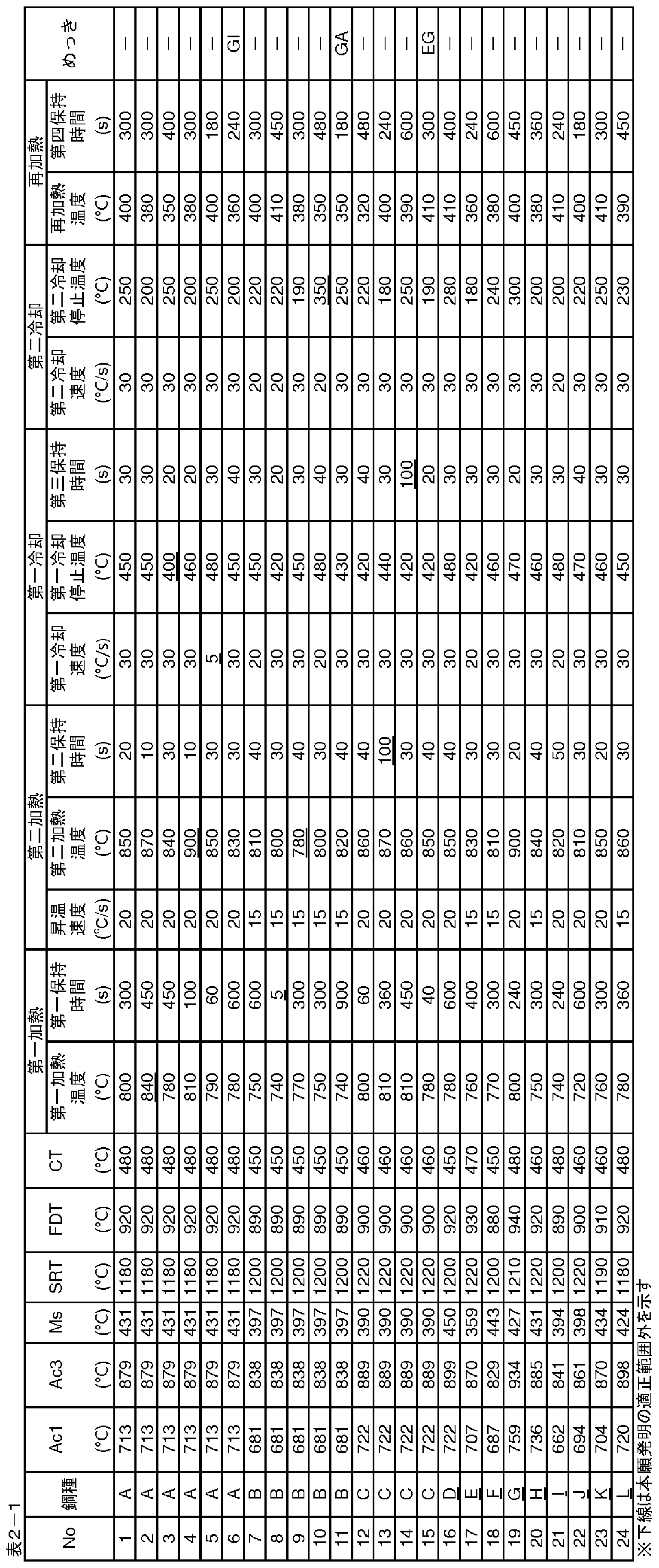
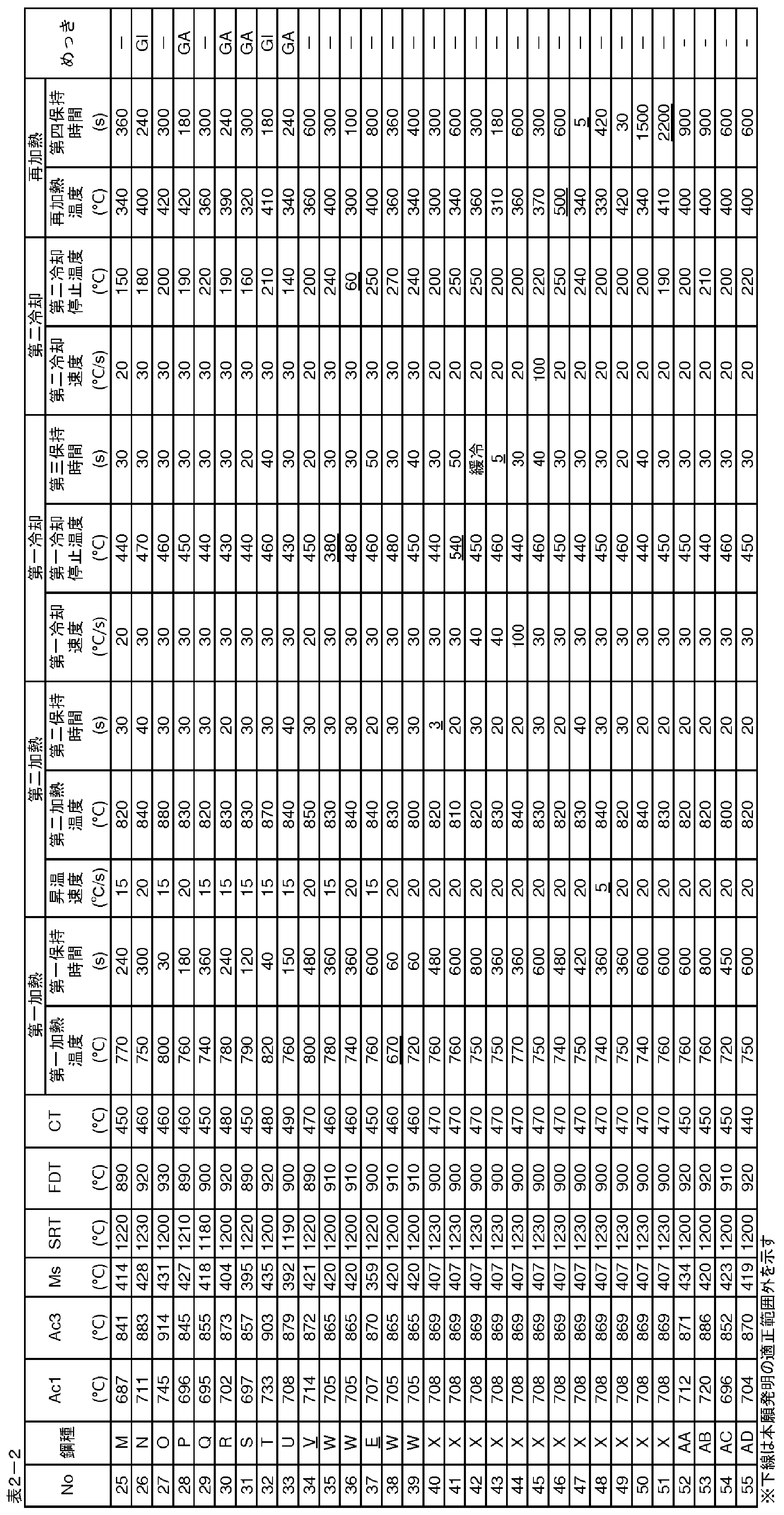


Claims (7)
- 質量%で,
C: 0.06%以上0.15%以下,
Si: 0.10%以上1.8%以下,
Mn: 2.00%以上3.50%以下,
P: 0.050%以下,
S: 0.0050%以下,
N: 0.0060%以下,
Al: 0.010%以上1.0%以下,
Ti: 0.005%以上0.075%以下,
Nb: 0.005%以上0.075%以下及び
B: 0.0002%以上0.0040%以下
を含み,残部がFe及び不可避的不純物からなり,[mol%N]/[mol%Ti]<1を満たす成分組成と,
フェライト: 面積分率で30%以上60%以下,
焼戻しマルテンサイト及びベイナイト: 面積分率で合計35%以上65%以下,
焼入れマルテンサイト: 面積分率で15%以下,
残留オーステナイト: 面積分率で1%以上10%以下,
0.8×[%Mn]以下のMn濃度を有する低Mnフェライトの面積分率が5%以上40%以下,
(前記フェライトの面積分率)-(前記低Mnフェライトの面積分率): 10%以上,
残部組織: 面積分率で3%未満,
かつ前記低Mnフェライトの平均結晶粒径が10μm以下である鋼組織を有する,高強度冷延鋼板。
ただし,[mol%N]及び[mol%Ti]は,それぞれN及びTiの鋼中含有量(mol%)を示し,[%Mn]はMnの鋼中含有量(質量%)を示す。 - 前記成分組成はさらに,質量%で,
V: 0.200%以下,
Cr: 0.20%以下,
Mo: 0.20%以下,
Cu: 0.30%以下,
Ni: 0.30%以下,
Sb: 0.100%以下,
Sn: 0.100%以下,
Ca: 0.0050%以下,
Mg: 0.0050%以下,
REM: 0.0050%以下,
Ta: 0.100%以下,
W: 0.500%以下,
Zr: 0.0200%以下及び
Co: 0.100%以下
のうちから選ばれる少なくとも1種の元素を含有する,請求項1に記載の高強度冷延鋼板。 - 請求項1または2に記載の高強度冷延鋼板の少なくとも片面にめっき層を有する,高強度めっき鋼板。
- 請求項1または2に記載の成分組成を有する鋼スラブに熱間圧延を施して熱延板とし,
前記熱延板に酸洗を施し,
酸洗後の前記熱延板に冷間圧延を施して冷延板とし,
次いで,前記冷延板をAc1点以上(Ac3点-50℃)以下の第一加熱温度まで加熱し,Ac1点以上(Ac3点-50℃)以下の第一加熱温度域にて10s以上保持する第一加熱工程を行い,
次いで,前記冷延板を,(前記第一加熱温度+20℃)以上Ac3点未満の第二加熱温度まで昇温速度10℃/s以上で加熱し,(前記第一加熱温度+20℃)以上Ac3点未満の第二加熱温度域にて5s以上60s以下保持する第二加熱工程を行い,
次いで,前記冷延板を,10℃/s以上の第一冷却速度で500℃以下Ms点超の第一冷却停止温度まで冷却した後,該第一冷却停止温度にて10s以上60s以下保持し,あるいは該第一冷却停止温度からMs点超まで10℃/s未満の第三冷却速度にて10s以上60s以下冷却する,第一冷却工程を行い,
次いで,前記冷延板を,10℃/s以上の第二冷却速度で(Ms点-100℃)以下100℃以上の第二冷却停止温度まで冷却する第二冷却工程を行い,
次いで,前記冷延板を,前記第二冷却停止温度以上450℃以下の再加熱温度まで再加熱し,前記第二冷却停止温度以上450℃以下の再加熱温度域にて10s以上1800s以下保持する再加熱工程を行なって,高強度冷延鋼板を得る,高強度冷延鋼板の製造方法。 - 請求項4に記載の再加熱工程の後,前記高強度冷延鋼板にめっき処理を施して高強度めっき鋼板を得る,高強度めっき鋼板の製造方法。
- 請求項1または2に記載の高強度冷延鋼板を少なくとも一部に用いてなる,自動車部品。
- 請求項3に記載の高強度めっき鋼板を少なくとも一部に用いてなる,自動車部品。
Priority Applications (6)
| Application Number | Priority Date | Filing Date | Title |
|---|---|---|---|
| US18/247,073 US12624408B2 (en) | 2020-10-13 | 2021-08-05 | High-strength cold-rolled steel sheet, high-strength coated or plated steel sheet, method of producing high-strength cold-rolled steel sheet, method of producing high-strength coated or plated steel sheet, and automotive part |
| EP21879729.8A EP4194577A4 (en) | 2020-10-13 | 2021-08-05 | High-strength cold-rolled steel plate, high-strength plated steel plate, method for manufacturing high-strength cold-rolled steel plate, method for manufacturing high-strength plated steel plate, and automobile part |
| JP2021569243A JP7070812B1 (ja) | 2020-10-13 | 2021-08-05 | 高強度冷延鋼板,高強度めっき鋼板,高強度冷延鋼板の製造方法,高強度めっき鋼板の製造方法,及び自動車部品 |
| KR1020237013243A KR102838048B1 (ko) | 2020-10-13 | 2021-08-05 | 고강도 냉연 강판, 고강도 도금 강판, 고강도 냉연 강판의 제조 방법, 고강도 도금 강판의 제조 방법 및, 자동차 부품 |
| CN202180069646.3A CN116323993B (zh) | 2020-10-13 | 2021-08-05 | 高强度冷轧钢板、高强度镀覆钢板、高强度冷轧钢板的制造方法、高强度镀覆钢板的制造方法以及汽车部件 |
| MX2023004291A MX2023004291A (es) | 2020-10-13 | 2021-08-05 | Lamina de acero laminada en frio de alta resistencia, lamina de acero recubierta o chapada de alta resistencia, metodo para producir lamina de acero laminada en frio de alta resistencia, metodo para producir lamina de acero recubierta o chapada de alta resistencia y pieza automotriz. |
Applications Claiming Priority (2)
| Application Number | Priority Date | Filing Date | Title |
|---|---|---|---|
| JP2020-172859 | 2020-10-13 | ||
| JP2020172859 | 2020-10-13 |
Publications (1)
| Publication Number | Publication Date |
|---|---|
| WO2022079987A1 true WO2022079987A1 (ja) | 2022-04-21 |
Family
ID=81207876
Family Applications (1)
| Application Number | Title | Priority Date | Filing Date |
|---|---|---|---|
| PCT/JP2021/029205 Ceased WO2022079987A1 (ja) | 2020-10-13 | 2021-08-05 | 高強度冷延鋼板,高強度めっき鋼板,高強度冷延鋼板の製造方法,高強度めっき鋼板の製造方法,及び自動車部品 |
Country Status (7)
| Country | Link |
|---|---|
| US (1) | US12624408B2 (ja) |
| EP (1) | EP4194577A4 (ja) |
| JP (1) | JP7070812B1 (ja) |
| KR (1) | KR102838048B1 (ja) |
| CN (1) | CN116323993B (ja) |
| MX (1) | MX2023004291A (ja) |
| WO (1) | WO2022079987A1 (ja) |
Cited By (3)
| Publication number | Priority date | Publication date | Assignee | Title |
|---|---|---|---|---|
| WO2025142033A1 (ja) * | 2023-12-26 | 2025-07-03 | Jfeスチール株式会社 | 鋼板、部材およびそれらの製造方法 |
| WO2025225586A1 (ja) * | 2024-04-25 | 2025-10-30 | Jfeスチール株式会社 | 亜鉛めっき鋼板、部材及びそれらの製造方法 |
| JP7859601B2 (ja) | 2024-04-25 | 2026-05-15 | Jfeスチール株式会社 | 亜鉛めっき鋼板、部材及びそれらの製造方法 |
Families Citing this family (1)
| Publication number | Priority date | Publication date | Assignee | Title |
|---|---|---|---|---|
| JP2025520669A (ja) | 2022-10-21 | 2025-07-03 | エルジー エナジー ソリューション リミテッド | 電極アセンブリ及びこれを含む電気化学素子 |
Citations (5)
| Publication number | Priority date | Publication date | Assignee | Title |
|---|---|---|---|---|
| WO2012118040A1 (ja) * | 2011-03-02 | 2012-09-07 | 株式会社神戸製鋼所 | 室温および温間での深絞り性に優れた高強度鋼板およびその温間加工方法 |
| JP5464302B2 (ja) | 2012-02-22 | 2014-04-09 | 新日鐵住金株式会社 | 冷延鋼板及びその製造方法 |
| JP2015193897A (ja) | 2014-03-17 | 2015-11-05 | 株式会社神戸製鋼所 | 延性及び曲げ性に優れた高強度冷延鋼板および高強度溶融亜鉛めっき鋼板、並びにそれらの製造方法 |
| WO2020145108A1 (ja) * | 2019-01-09 | 2020-07-16 | Jfeスチール株式会社 | 高強度冷延鋼板及びその製造方法 |
| JP2020164990A (ja) * | 2019-03-26 | 2020-10-08 | Jfeスチール株式会社 | 高強度鋼板およびその製造方法 |
Family Cites Families (11)
| Publication number | Priority date | Publication date | Assignee | Title |
|---|---|---|---|---|
| JP5493986B2 (ja) * | 2009-04-27 | 2014-05-14 | Jfeスチール株式会社 | 加工性に優れた高強度鋼板および高強度溶融亜鉛めっき鋼板並びにそれらの製造方法 |
| JP5348268B2 (ja) * | 2012-03-07 | 2013-11-20 | Jfeスチール株式会社 | 成形性に優れる高強度冷延鋼板およびその製造方法 |
| JP5821911B2 (ja) | 2013-08-09 | 2015-11-24 | Jfeスチール株式会社 | 高降伏比高強度冷延鋼板およびその製造方法 |
| JP6179461B2 (ja) * | 2014-05-27 | 2017-08-16 | Jfeスチール株式会社 | 高強度鋼板の製造方法 |
| JP6282576B2 (ja) | 2014-11-21 | 2018-02-21 | 株式会社神戸製鋼所 | 高強度高延性鋼板 |
| JP6554397B2 (ja) * | 2015-03-31 | 2019-07-31 | 株式会社神戸製鋼所 | 加工性および衝突特性に優れた引張強度が980MPa以上の高強度冷延鋼板、およびその製造方法 |
| JP6168118B2 (ja) | 2015-10-19 | 2017-07-26 | Jfeスチール株式会社 | ホットプレス部材およびその製造方法 |
| WO2017208763A1 (ja) | 2016-05-30 | 2017-12-07 | 株式会社神戸製鋼所 | 高強度鋼板およびその製造方法 |
| JP6323627B1 (ja) * | 2016-08-31 | 2018-05-16 | Jfeスチール株式会社 | 高強度冷延薄鋼板及びその製造方法 |
| WO2019151017A1 (ja) | 2018-01-31 | 2019-08-08 | Jfeスチール株式会社 | 高強度冷延鋼板、高強度めっき鋼板及びそれらの製造方法 |
| KR102838050B1 (ko) * | 2020-10-13 | 2025-07-24 | 제이에프이 스틸 가부시키가이샤 | 고강도 냉연 강판, 고강도 도금 강판, 고강도 냉연 강판의 제조 방법, 고강도 도금 강판의 제조 방법 및, 자동차 부품 |
-
2021
- 2021-08-05 KR KR1020237013243A patent/KR102838048B1/ko active Active
- 2021-08-05 MX MX2023004291A patent/MX2023004291A/es unknown
- 2021-08-05 JP JP2021569243A patent/JP7070812B1/ja active Active
- 2021-08-05 CN CN202180069646.3A patent/CN116323993B/zh active Active
- 2021-08-05 US US18/247,073 patent/US12624408B2/en active Active
- 2021-08-05 WO PCT/JP2021/029205 patent/WO2022079987A1/ja not_active Ceased
- 2021-08-05 EP EP21879729.8A patent/EP4194577A4/en active Pending
Patent Citations (5)
| Publication number | Priority date | Publication date | Assignee | Title |
|---|---|---|---|---|
| WO2012118040A1 (ja) * | 2011-03-02 | 2012-09-07 | 株式会社神戸製鋼所 | 室温および温間での深絞り性に優れた高強度鋼板およびその温間加工方法 |
| JP5464302B2 (ja) | 2012-02-22 | 2014-04-09 | 新日鐵住金株式会社 | 冷延鋼板及びその製造方法 |
| JP2015193897A (ja) | 2014-03-17 | 2015-11-05 | 株式会社神戸製鋼所 | 延性及び曲げ性に優れた高強度冷延鋼板および高強度溶融亜鉛めっき鋼板、並びにそれらの製造方法 |
| WO2020145108A1 (ja) * | 2019-01-09 | 2020-07-16 | Jfeスチール株式会社 | 高強度冷延鋼板及びその製造方法 |
| JP2020164990A (ja) * | 2019-03-26 | 2020-10-08 | Jfeスチール株式会社 | 高強度鋼板およびその製造方法 |
Non-Patent Citations (1)
| Title |
|---|
| See also references of EP4194577A4 |
Cited By (5)
| Publication number | Priority date | Publication date | Assignee | Title |
|---|---|---|---|---|
| WO2025142033A1 (ja) * | 2023-12-26 | 2025-07-03 | Jfeスチール株式会社 | 鋼板、部材およびそれらの製造方法 |
| JP7772274B1 (ja) * | 2023-12-26 | 2025-11-18 | Jfeスチール株式会社 | 鋼板、部材およびそれらの製造方法 |
| WO2025225586A1 (ja) * | 2024-04-25 | 2025-10-30 | Jfeスチール株式会社 | 亜鉛めっき鋼板、部材及びそれらの製造方法 |
| JPWO2025225586A1 (ja) * | 2024-04-25 | 2025-10-30 | ||
| JP7859601B2 (ja) | 2024-04-25 | 2026-05-15 | Jfeスチール株式会社 | 亜鉛めっき鋼板、部材及びそれらの製造方法 |
Also Published As
| Publication number | Publication date |
|---|---|
| EP4194577A4 (en) | 2025-05-28 |
| CN116323993A (zh) | 2023-06-23 |
| KR102838048B1 (ko) | 2025-07-24 |
| US12624408B2 (en) | 2026-05-12 |
| CN116323993B (zh) | 2025-06-03 |
| EP4194577A1 (en) | 2023-06-14 |
| KR20230070481A (ko) | 2023-05-23 |
| MX2023004291A (es) | 2023-05-03 |
| JPWO2022079987A1 (ja) | 2022-04-21 |
| JP7070812B1 (ja) | 2022-05-18 |
| US20230235421A1 (en) | 2023-07-27 |
Similar Documents
| Publication | Publication Date | Title |
|---|---|---|
| US10435762B2 (en) | High-yield-ratio high-strength cold-rolled steel sheet and method of producing the same | |
| JP6252710B2 (ja) | 温間加工用高強度鋼板およびその製造方法 | |
| JP7078186B1 (ja) | 高強度冷延鋼板,高強度めっき鋼板,高強度冷延鋼板の製造方法,及び高強度めっき鋼板の製造方法 | |
| US11225701B2 (en) | Hot dip galvanized steel sheet and hot dip galvannealed steel sheet | |
| US20170283902A1 (en) | Hot dip galvanized and galvannealed steel sheet having excellent elongation properties | |
| US20250369065A1 (en) | High-strength steel sheet and method for producing the same | |
| US20170204490A1 (en) | High-strength steel sheet and production method for same, and production method for high-strength galvanized steel sheet | |
| CN115151673B (zh) | 钢板、构件和它们的制造方法 | |
| US12258647B2 (en) | Steel sheet, member, and methods for manufacturing the same | |
| CN116018416B (zh) | 钢板及其制造方法 | |
| JP7070812B1 (ja) | 高強度冷延鋼板,高強度めっき鋼板,高強度冷延鋼板の製造方法,高強度めっき鋼板の製造方法,及び自動車部品 | |
| JP6947327B2 (ja) | 高強度鋼板、高強度部材及びそれらの製造方法 | |
| CN115210398B (zh) | 钢板、构件和它们的制造方法 | |
| JP2018003114A (ja) | 高強度鋼板およびその製造方法 | |
| JP2018003115A (ja) | 高強度鋼板およびその製造方法 | |
| JP7838657B2 (ja) | 鋼板、部材及びそれらの製造方法 | |
| WO2026094753A1 (ja) | 冷間プレス成形用の鋼板、めっき鋼板、鋼板の製造方法、めっき鋼板の製造方法、部材および部材の製造方法 | |
| KR20220085859A (ko) | 강도, 성형성 및 표면 품질이 우수한 도금강판 및 이의 제조방법 |
Legal Events
| Date | Code | Title | Description |
|---|---|---|---|
| ENP | Entry into the national phase |
Ref document number: 2021569243 Country of ref document: JP Kind code of ref document: A |
|
| 121 | Ep: the epo has been informed by wipo that ep was designated in this application |
Ref document number: 21879729 Country of ref document: EP Kind code of ref document: A1 |
|
| WWE | Wipo information: entry into national phase |
Ref document number: 202317015324 Country of ref document: IN |
|
| ENP | Entry into the national phase |
Ref document number: 2021879729 Country of ref document: EP Effective date: 20230308 |
|
| ENP | Entry into the national phase |
Ref document number: 20237013243 Country of ref document: KR Kind code of ref document: A |
|
| NENP | Non-entry into the national phase |
Ref country code: DE |
|
| WWG | Wipo information: grant in national office |
Ref document number: 202180069646.3 Country of ref document: CN |
|
| WWG | Wipo information: grant in national office |
Ref document number: 1020237013243 Country of ref document: KR |