WO2022080025A1 - 建設機械 - Google Patents
建設機械 Download PDFInfo
- Publication number
- WO2022080025A1 WO2022080025A1 PCT/JP2021/031937 JP2021031937W WO2022080025A1 WO 2022080025 A1 WO2022080025 A1 WO 2022080025A1 JP 2021031937 W JP2021031937 W JP 2021031937W WO 2022080025 A1 WO2022080025 A1 WO 2022080025A1
- Authority
- WO
- WIPO (PCT)
- Prior art keywords
- unit
- mode
- construction machine
- monitoring
- execution
- Prior art date
- Legal status (The legal status is an assumption and is not a legal conclusion. Google has not performed a legal analysis and makes no representation as to the accuracy of the status listed.)
- Ceased
Links
Images


Classifications
-
- E—FIXED CONSTRUCTIONS
- E02—HYDRAULIC ENGINEERING; FOUNDATIONS; SOIL SHIFTING
- E02F—DREDGING; SOIL-SHIFTING
- E02F9/00—Component parts of dredgers or soil-shifting machines, not restricted to one of the kinds covered by groups E02F3/00 - E02F7/00
- E02F9/26—Indicating devices
- E02F9/261—Surveying the work-site to be treated
- E02F9/262—Surveying the work-site to be treated with follow-up actions to control the work tool, e.g. controller
-
- E—FIXED CONSTRUCTIONS
- E02—HYDRAULIC ENGINEERING; FOUNDATIONS; SOIL SHIFTING
- E02F—DREDGING; SOIL-SHIFTING
- E02F9/00—Component parts of dredgers or soil-shifting machines, not restricted to one of the kinds covered by groups E02F3/00 - E02F7/00
- E02F9/24—Safety devices, e.g. for preventing overload
-
- B—PERFORMING OPERATIONS; TRANSPORTING
- B60—VEHICLES IN GENERAL
- B60Q—ARRANGEMENT OF SIGNALLING OR LIGHTING DEVICES, THE MOUNTING OR SUPPORTING THEREOF OR CIRCUITS THEREFOR, FOR VEHICLES IN GENERAL
- B60Q9/00—Arrangement or adaptation of signal devices not provided for in one of main groups B60Q1/00 - B60Q7/00, e.g. haptic signalling
- B60Q9/008—Arrangement or adaptation of signal devices not provided for in one of main groups B60Q1/00 - B60Q7/00, e.g. haptic signalling for anti-collision purposes
-
- B—PERFORMING OPERATIONS; TRANSPORTING
- B60—VEHICLES IN GENERAL
- B60R—VEHICLES, VEHICLE FITTINGS, OR VEHICLE PARTS, NOT OTHERWISE PROVIDED FOR
- B60R1/00—Optical viewing arrangements; Real-time viewing arrangements for drivers or passengers using optical image capturing systems, e.g. cameras or video systems specially adapted for use in or on vehicles
- B60R1/20—Real-time viewing arrangements for drivers or passengers using optical image capturing systems, e.g. cameras or video systems specially adapted for use in or on vehicles
- B60R1/22—Real-time viewing arrangements for drivers or passengers using optical image capturing systems, e.g. cameras or video systems specially adapted for use in or on vehicles for viewing an area outside the vehicle, e.g. the exterior of the vehicle
- B60R1/23—Real-time viewing arrangements for drivers or passengers using optical image capturing systems, e.g. cameras or video systems specially adapted for use in or on vehicles for viewing an area outside the vehicle, e.g. the exterior of the vehicle with a predetermined field of view
- B60R1/27—Real-time viewing arrangements for drivers or passengers using optical image capturing systems, e.g. cameras or video systems specially adapted for use in or on vehicles for viewing an area outside the vehicle, e.g. the exterior of the vehicle with a predetermined field of view providing all-round vision, e.g. using omnidirectional cameras
-
- E—FIXED CONSTRUCTIONS
- E02—HYDRAULIC ENGINEERING; FOUNDATIONS; SOIL SHIFTING
- E02F—DREDGING; SOIL-SHIFTING
- E02F9/00—Component parts of dredgers or soil-shifting machines, not restricted to one of the kinds covered by groups E02F3/00 - E02F7/00
- E02F9/20—Drives; Control devices
- E02F9/2025—Particular purposes of control systems not otherwise provided for
- E02F9/2033—Limiting the movement of frames or implements, e.g. to avoid collision between implements and the cabin
-
- E—FIXED CONSTRUCTIONS
- E02—HYDRAULIC ENGINEERING; FOUNDATIONS; SOIL SHIFTING
- E02F—DREDGING; SOIL-SHIFTING
- E02F9/00—Component parts of dredgers or soil-shifting machines, not restricted to one of the kinds covered by groups E02F3/00 - E02F7/00
- E02F9/26—Indicating devices
-
- B—PERFORMING OPERATIONS; TRANSPORTING
- B60—VEHICLES IN GENERAL
- B60Y—INDEXING SCHEME RELATING TO ASPECTS CROSS-CUTTING VEHICLE TECHNOLOGY
- B60Y2200/00—Type of vehicle
- B60Y2200/40—Special vehicles
- B60Y2200/41—Construction vehicles, e.g. graders, excavators
- B60Y2200/412—Excavators
-
- E—FIXED CONSTRUCTIONS
- E02—HYDRAULIC ENGINEERING; FOUNDATIONS; SOIL SHIFTING
- E02F—DREDGING; SOIL-SHIFTING
- E02F3/00—Dredgers; Soil-shifting machines
- E02F3/04—Dredgers; Soil-shifting machines mechanically-driven
- E02F3/28—Dredgers; Soil-shifting machines mechanically-driven with digging tools mounted on a dipper- or bucket-arm, i.e. there is either one arm or a pair of arms, e.g. dippers, buckets
- E02F3/30—Dredgers; Soil-shifting machines mechanically-driven with digging tools mounted on a dipper- or bucket-arm, i.e. there is either one arm or a pair of arms, e.g. dippers, buckets with a dipper-arm pivoted on a cantilever beam, i.e. boom
- E02F3/32—Dredgers; Soil-shifting machines mechanically-driven with digging tools mounted on a dipper- or bucket-arm, i.e. there is either one arm or a pair of arms, e.g. dippers, buckets with a dipper-arm pivoted on a cantilever beam, i.e. boom working downwardly and towards the machine, e.g. with backhoes
- E02F3/325—Backhoes of the miniature type
Definitions
- the present invention relates to construction machinery.
- Patent Document 1 discloses a shovel that limits the operation of the shovel when an object is detected around the shovel by the object detecting means, or notifies that the object has been detected.
- the operation mode of the excavator includes a specific operation mode (hereinafter, also referred to as a specific mode) such as a crane mode for suspending work in addition to a normal mode for performing normal operation or work such as running, turning, and excavation.
- a specific mode such as a crane mode for suspending work in addition to a normal mode for performing normal operation or work such as running, turning, and excavation.
- the present invention has been made to solve the above-mentioned problems, and an object thereof is usually caused by an operation regulation based on a state around a construction machine in an operation mode other than a specific mode (for example, a crane mode). While avoiding the dangers gained, the particular mode is to provide construction machinery that can ensure work safety by avoiding the dangers that arise when restricting operation.
- a specific mode for example, a crane mode
- the construction machine controls the execution of the operation regulation of the construction machine based on the monitoring result of the monitoring unit and the monitoring unit that monitors the surroundings of the construction machine according to the operation mode of the construction machine.
- the control unit executes the operation regulation based on the monitoring result, while the operation mode is the specific mode. In this case, the execution of the operation regulation based on the monitoring result is stopped.
- FIG. 1 is a side view showing a schematic configuration of a hydraulic excavator 1, which is an example of a construction machine of the present embodiment.
- the hydraulic excavator 1 includes a lower traveling body 2, a working machine 3, and an upper turning body 4.
- the direction is defined as follows. First, the direction in which the lower traveling body 2 goes straight is the front-rear direction, one side of which is “front”, and the other side is “rear”. In FIG. 1, as an example, the blade 23 side is shown as “front” with respect to the traveling motor 22. Further, the horizontal direction perpendicular to the front-rear direction is defined as the left-right direction. At this time, the left side is defined as “left” and the right side is defined as "right” when viewed from the operator (operator) sitting in the driver's seat 41a. Further, the gravity direction perpendicular to the front-back direction and the left-right direction is the vertical direction, the upstream side in the gravity direction is "up”, and the downstream side is "down".
- the lower traveling body 2 receives power from the engine 40 and is driven to drive the hydraulic excavator 1.
- the lower traveling body 2 includes a pair of left and right crawlers 21 and a pair of left and right traveling motors 22.
- Each traveling motor 22 is a hydraulic motor.
- the left and right traveling motors 22 drive the left and right crawlers 21, respectively, so that the hydraulic excavator 1 can be moved forward and backward.
- the lower traveling body 2 is provided with a blade 23 for performing ground leveling work and a blade cylinder 23a.
- the blade cylinder 23a is a hydraulic cylinder that rotates the blade 23 in the vertical direction.
- the work machine 3 is driven by receiving power from the engine 40 to perform excavation work for digging up earth and sand.
- the working machine 3 includes a boom 31, an arm 32, and a bucket 33. By independently driving the boom 31, arm 32, and bucket 33, excavation work can be performed.
- the boom 31 is rotated by the boom cylinder 31a.
- the base end of the boom cylinder 31a is supported by the front portion of the upper swing body 4, and the boom cylinder 31a can be expanded and contracted.
- the arm 32 is rotated by the arm cylinder 32a.
- the base end of the arm cylinder 32a is supported by the tip of the boom 31, and the arm cylinder 32a can be expanded and contracted.
- the bucket 33 is rotated by the bucket cylinder 33a.
- the base end of the bucket cylinder 33a is supported by the tip of the arm 32, and the bucket cylinder 33a can be expanded and contracted.
- the boom cylinder 31a, the arm cylinder 32a, and the bucket cylinder 33a are composed of hydraulic cylinders.
- the bucket 33 is a container-shaped member provided at the tip of the work machine 3 and provided with claws for performing excavation work.
- the bucket 33 is rotatably attached to the tip of the arm 32 via a pin 34. Further, the bucket 33 is connected to the bucket cylinder 33a via the link mechanism 35.
- a hook 36 for crane work is attached to the tip of the arm 32.
- the hook 36 is a hook-shaped member that performs crane work, and is rotatably provided on the link mechanism 35.
- the crane work refers to a hanging work of suspending and raising / lowering an object to be suspended.
- the hook 36 is rotatably supported with the axis of the link mechanism 35 as a rotation fulcrum, and is in a deployed state (see FIG. 1) protruding from the bucket 33 and a stored state stored in the bucket 33 side (not shown). ) And the posture can be changed. For example, when excavating with the bucket 33, the hook 36 is stored. On the other hand, when the crane work is performed by the hook 36, the hook 36 is put into the deployed state.
- the upper swivel body 4 is configured to be swivelable with respect to the lower traveling body 2 via a swivel bearing (not shown).
- a control unit 41, a swivel table 42, a swivel motor 43, an engine room 44, and the like are arranged in the upper swivel body 4.
- the upper swivel body 4 is swiveled via a swivel bearing by being driven by a swivel motor 43 which is a hydraulic motor.
- a plurality of hydraulic pumps P0 are arranged in addition to the engine 40 that provides power to each part.
- Each hydraulic pump P0 supplies hydraulic oil (pressure oil) to a hydraulic motor (for example, left and right traveling motors 22 and swivel motor 43) and a hydraulic cylinder (for example, blade cylinder 23a, boom cylinder 31a, arm cylinder 32a, bucket cylinder 33a). Supply.
- a hydraulic motor and a hydraulic cylinder driven by supplying hydraulic oil from an arbitrary hydraulic pump P0 are collectively referred to as a hydraulic actuator AC (see FIG. 2).
- a driver's seat 41a is arranged in the control unit 41 on which the operator rides.
- An operation unit 41b is arranged around the driver's seat 41a (particularly forward, left and right).
- the operation unit 41b is composed of an operation lever, a switch, a button, etc. for driving the hydraulic actuator AC.
- the hydraulic actuator AC is driven by the operator sitting on the driver's seat 41a and operating the operation unit 41b.
- the lower traveling body 2 can travel, the ground leveling work by the blade 23, the excavation work by the working machine 3, the crane work, the turning of the upper turning body 4, and the like can be performed.
- the hydraulic excavator 1 has a normal mode and a crane mode as operation modes.
- the normal mode is an operation mode in which operations such as traveling (driving the lower traveling body 2), turning (driving the upper rotating body 4), excavation (driving the working machine 3), or performing operations are performed.
- the operation unit 41b By operating the operation unit 41b, the operator can operate the hydraulic excavator 1 in the normal mode to execute traveling, turning, excavation, and the like.
- the crane mode is an operation mode in which an object is suspended by a hook 36 to perform a crane operation. The operator can make the hydraulic excavator 1 execute the crane operation by operating the input unit 72 (see FIG. 2) described later to set the crane mode and operating the operation unit 41b.
- FIG. 2 schematically shows the configuration of the main part of the hydraulic excavator 1.
- the hydraulic excavator 1 further includes a monitoring unit 50, a control unit 60, a monitoring device 70, a rotary lamp 81, a light emitting unit 82, and a warning unit 83.
- the monitoring unit 50 monitors the surroundings by detecting the presence or absence of obstacles around the hydraulic excavator 1.
- the above obstacles include objects to be monitored such as people, objects, and animals.
- the hydraulic excavator 1 includes a monitoring unit 50 that monitors the surroundings of the hydraulic excavator 1.
- the monitoring unit 50 monitors the surroundings of the hydraulic excavator 1 by acquiring an image of the surroundings of the hydraulic excavator 1. More specifically, the monitoring unit 50 has the following configuration.
- the monitoring unit 50 includes an imaging unit 51, an image processing unit 52, and a bird's-eye view image generation unit 53.
- the image pickup unit 51 includes a left camera 51a, a right camera 51b, and a rear camera 51c that capture images on the left, right, and rear of the hydraulic excavator 1, respectively.
- the image acquired by the imaging unit 51 by shooting is, for example, a moving image, but it may be a still image acquired by shooting at a predetermined frame cycle.
- the image processing unit 52 detects whether or not the object included in the image is an obstacle by performing image recognition processing by inputting an image acquired by the image pickup unit 51 (for example, an image taken on the right side). At the same time, it detects intruders in the monitoring area.
- the bird's-eye view image generation unit 53 is a bird's-eye view image centered on the hydraulic excavator 1 by image processing from a plurality of images acquired by a plurality of cameras (left camera 51a, right camera 51b, rear camera 51c) of the imaging unit 51. Generate a bird's-eye view image).
- the image processing unit 52 and the bird's-eye view image generation unit 53 described above are configured by, for example, a central processing unit called a CPU (Central Processing Unit) or an arithmetic unit such as a GPU (Graphics Processing Unit).
- a CPU Central Processing Unit
- arithmetic unit such as a GPU (Graphics Processing Unit).
- the number of cameras, the installation location, and the installation method are not particularly limited as long as the monitoring unit 50 can detect obstacles within the required range.
- the obstacle may be detected by using an obstacle sensor instead of the camera.
- the obstacle sensor a known distance measuring device capable of acquiring the distance information of the obstacle can be used.
- an ultrasonic radar using ultrasonic waves, a millimeter wave radar using radio waves in the millimeter wave band, a rider (LIDER) that measures scattered light for laser irradiation to determine the distance, and multiple camera functions are integrated.
- a stereo camera or the like that measures the distance from the captured image to the object can be used as an obstacle sensor.
- the control unit 60 controls the operation of each unit of the hydraulic excavator 1.
- the control unit 60 executes the operation regulation of the hydraulic excavator 1 based on the monitoring result of the monitoring unit 50, and operates the hydraulic excavator 1.
- the mode is, for example, the crane mode
- the execution of the operation regulation of the hydraulic excavator 1 based on the monitoring result of the monitoring unit 50 is stopped.
- the hydraulic excavator 1 includes a control unit 60 that controls the execution of the operation regulation of the hydraulic excavator 1 based on the monitoring result of the monitoring unit 50 according to the operation mode of the hydraulic excavator 1.
- Such a control unit 60 is composed of an electronic control unit called an ECU (Electronic Control Unit).
- the above-mentioned operation regulation includes, for example, complete stop of operation such as running, limitation of running speed (decrease), reduction of engine speed, and the like. The details of the operation under the control of the control unit 60 will be described later.
- the control unit 60 may include a storage unit.
- the storage unit stores a program for operating the control unit 60 and various types of information.
- a RAM Random Access Memory
- ROM Read Only Memory
- non-volatile memory or the like can be used.
- the monitoring device 70 is arranged in the vicinity of the driver's seat 41a (for example, diagonally forward), displays various information, and provides necessary information to the operator seated in the driver's seat 41a.
- the monitoring device 70 has a display unit 71 and an input unit 72.
- the monitor device 70 itself may be provided with an ECU (monitor ECU) inside, and each part in the monitor device 70 may be controlled by the monitor ECU.
- the display unit 71 is composed of, for example, a liquid crystal display device, and displays an image acquired by the monitoring unit 50.
- FIG. 3 schematically shows an example of the display screen of the display unit 71.
- the bird's-eye view image Bv created by the image processing unit 52 from the images taken and acquired by each of the left camera 51a, the right camera 51b, and the rear camera 51c constituting the imaging unit 51 of the monitoring unit 50 is displayed in the display unit.
- the state displayed in 71 is shown.
- the hydraulic excavator 1 of the present embodiment includes a display unit 71 that displays an image acquired by the monitoring unit 50.
- the display unit 71 displays information (icon, text, etc.) indicating that the obstacle has been detected.
- information icon, text, etc.
- FIG. 3 in the bird's-eye view image Bv, when a “person”, which is an example of an obstacle, is detected on the left side and the rear side of the hydraulic excavator 1 by the monitoring unit 50, the obstacle on the left side is the “person”.
- An icon M1 indicating that there is, an icon A1 indicating a left-pointing arrow indicating that a "person” has been detected on the left side of the hydraulic excavator 1, and an icon A1 indicating that the detection direction is on the left side with respect to the hydraulic excavator 1.
- Position information P1 (shown by the thick arc of the broken line in FIG. 3), the icon M2 indicating that the obstacle behind is a "person", and the rear indicating that a "person” has been detected behind the hydraulic excavator 1.
- the icon A2 indicating the direction arrow and the position information P2 (shown by the thick arc in practice in FIG. 3) indicating that the detection direction is behind the hydraulic excavator 1 display the bird's-eye view image Bv on the display unit 71. It shows the state of being displayed at the same time outside the area.
- the operator sees the icon M1 or the like displayed on the display unit 71, and the monitoring unit 50 detects an obstacle, and the type of the obstacle (the obstacle type ( Whether or not it is a person) and the detection direction of obstacles can be grasped immediately.
- the type of the obstacle the obstacle type ( Whether or not it is a person) and the detection direction of obstacles can be grasped immediately.
- the icon may be displayed in different colors on the display unit 71 according to the distance from the hydraulic excavator 1 to the obstacle. For example, when the distance from the hydraulic excavator 1 to an obstacle is measured by the monitoring unit 50, if the distance is less than 2 m, the icon M1 or the like is displayed in yellow, and if the distance is 2 m or more, the icon M1 or the like is displayed in red. The icon M1 or the like may be displayed.
- the display unit 71 has information indicating that the execution of the operation regulation is stopped when the execution of the operation regulation based on the monitoring result of the monitoring unit 50 is stopped in a specific operation mode (for example, the crane mode). Is also displayed.
- FIG. 3 shows a state in which the text information of "operation restriction system is stopped” is displayed on the upper side of the display area of the bird's-eye view image Bv in the display unit 71 as the information R indicating the execution stop of the operation restriction. ..
- a specific operation mode such as a crane mode is also referred to as a "specific mode" below.
- the display unit 71 also displays various information such as whether or not the operation mode of the hydraulic excavator 1 is the crane mode, the amount of fuel, and warning information regarding seatbelt wearing. Further, when the operation mode is the crane mode, information on the rated weight (for example, 3.0t in FIG. 3) and the current suspension load (for example, 2.8t in FIG. 3) is also displayed on the display unit 71.
- the input unit 72 is operated by an operator to set and input various information.
- the input unit 72 is composed of, for example, a touch panel input device arranged so as to be superimposed on the display unit 71.
- the input unit 72 may be composed of a mechanical input button or a jog dial.
- the crane mode can be set as the operation mode of the hydraulic excavator 1.
- the crane mode can be set by the operator pressing the display area (input position of the input unit 72) of the “crane” on the display screen of the display unit 71.
- the hydraulic excavator 1 includes an input unit 72 that accepts the setting of the specific mode.
- the operator presses the display area (input position of the input unit 72) of the "camera” on the display screen of the display unit 71, so that the image displayed on the display unit 71 can be displayed as a bird's-eye view image Bv and individual images. It can be switched between a camera image (an image acquired by the left camera 51a, an image acquired by the right camera 51b, and an image acquired by the rear camera 51c).
- the rotary lamp 81 shown in FIG. 2 is composed of a lamp that rotates when the monitoring unit 50 detects an obstacle.
- the light emitting unit 82 is composed of, for example, a light emitting diode (LED), and lights up or blinks when the monitoring unit 50 detects an obstacle.
- the alarm unit 83 includes a buzzer that outputs a sound when the monitoring unit 50 detects an obstacle.
- the alarm unit 83 may be composed of a voice output unit that outputs a voice (electronic sound) when the monitoring unit 50 detects an obstacle. The operator can recognize that the monitoring unit 50 has detected an obstacle by rotating the lamp of the rotating lamp 82, lighting (or blinking) the light emitting unit 82, and outputting a buzzer sound or a voice by the alarm unit 63.
- the display unit 71, the rotary lamp 81, the light emitting unit 82, and the alarm unit 83 of the monitor device 70 display an icon or the like, rotate the lamp, and emit light when the monitoring unit 50 detects an obstacle. , Outputs an alarm by sound output. From this, it can be said that the display unit 71, the rotary lamp 81, the light emitting unit 82, and the alarm unit 83 constitute an alarm device 90 that outputs an alarm based on the monitoring result of the monitoring unit 50. That is, the hydraulic excavator 1 of the present embodiment includes an alarm device 90 that outputs an alarm based on the monitoring result of the monitoring unit 50. It should be noted that the alarm device 90 does not have to include all of the display unit 71, the rotating lamp 81, the light emitting unit 82, and the alarm unit 83, and may be configured to include at least one of them.
- the control unit 60 stops executing the operation restriction of the hydraulic excavator 1 in the specific mode (for example, the crane mode).
- the lamp of the rotary lamp 81 rotates and the light emitting unit 82 lights up or blinks.
- the alarm unit 83 outputs a sound or a voice indicating that the execution of the operation regulation has been stopped. Therefore, in the display unit 71, the rotary lamp 81, the light emitting unit 82, and the alarm unit 83 of the monitor device 70, the control unit 60 stops executing the operation regulation of the hydraulic excavator 1 in a specific operation mode (for example, a crane mode).
- a specific operation mode for example, a crane mode
- the execution stop notification device 100 for notifying that the execution of the operation regulation has been stopped is configured by the display, the rotation of the lamp, the light emission, and the output of the sound. That is, the hydraulic excavator 1 of the present embodiment includes an execution stop notification device 100 that notifies the execution stop of the operation regulation when the control unit 60 stops the execution of the operation regulation based on the monitoring result of the monitoring unit 50. It should be noted that the execution stop notification device 100 does not have to include all of the display unit 71, the rotary lamp 81, the light emitting unit 82, and the alarm unit 83, and may be configured to include at least one of them.
- the hydraulic excavator 1 includes a plurality of hydraulic actuators AC, a hydraulic pump P0 for pumping pressure oil to the plurality of hydraulic actuator ACs, and a pilot pump PP.
- FIG. 2 shows a hydraulic circuit corresponding to one hydraulic actuator AC for convenience, the same hydraulic circuit is configured for the other hydraulic actuator AC.
- the plurality of hydraulic actuators AC are left and right traveling motors 22 which are traveling hydraulic actuators for driving the lower traveling body 2, blade cylinders 23a which are hydraulic actuators for rotating the blades 23 up and down, and turning for driving the upper swinging body 3. It includes a swivel motor 43 which is a hydraulic actuator, a boom cylinder 31a, an arm cylinder 32a, and a bucket cylinder 33a which are working hydraulic actuators for driving a working machine 3.
- the blade cylinder 23a, boom cylinder 31a, arm cylinder 32a, and bucket cylinder 33a are collectively referred to as a hydraulic cylinder CY.
- the hydraulic excavator 1 may be configured to have a so-called boom swing function of swinging the working machine 3 (boom 31) left and right with respect to the upper swing body 4.
- the hydraulic cylinder CY also includes a swing cylinder which is a hydraulic actuator for swinging the boom 31.
- the boom swing function is installed in a mini excavator (small hydraulic excavator) used for construction in a narrow space.
- the plurality of hydraulic pumps P0 include a variable capacity pump and a fixed capacity pump, and are driven by the engine 40.
- the variable displacement pump pumps pressure oil to the left and right traveling motors 22, the boom cylinder 31a, the arm cylinder 32a, and the bucket cylinder 33a.
- the fixed-capacity pump pumps pressure oil to the blade cylinder 23a, the swivel motor 43, and the swing cylinder (not shown).
- Each of the plurality of actuators AC is provided with a corresponding direction switching valve CV.
- This directional control valve CV is a pilot-type directional control valve that can switch the direction and flow rate of the pressure oil pumped from the hydraulic pump P0 (variable capacity pump or fixed capacity pump), and is also called a control valve.
- the direction switching valve CV of the present embodiment includes a direction switching valve corresponding to the left and right traveling motors 22, a direction switching valve corresponding to the boom cylinder 31a, a direction switching valve corresponding to the arm cylinder 32a, and a direction corresponding to the bucket cylinder 33a.
- a switching valve, a directional switching valve corresponding to the blade cylinder 23a, a directional switching valve corresponding to the swivel motor 43, and a directional switching valve corresponding to the swing cylinder are included.
- the pilot pump PP discharges pilot oil, which is an input command to the directional control valve CV.
- the pilot pump PP driven by the engine 40 generates a pilot pressure in the pilot oil passage by discharging the pressure oil.
- a pilot oil passage is provided from the pilot pump PP to each of the directional control valves CV.
- the operation unit 41b has a remote control valve RV for switching the direction and pressure of the pressure oil supplied to the direction switching valve CV.
- the pressure oil discharged from the pilot pump PP is supplied to the remote control valve RV.
- the remote control valve RV generates a pilot pressure according to the operation direction and the operation amount of the operation unit 41b.
- the operation unit 41b includes, for example, a traveling lever for traveling the hydraulic excavator 1 and a steering lever for operating the working machine 3 and the like.
- a solenoid valve SV is provided in the oil passage between the pilot pump PP and each remote control valve RV.
- the solenoid valve SV adjusts the pilot pressure generated by the pilot pump PP in response to a control command from the control unit 60.
- the pilot pressure for example, the drive of the plurality of hydraulic actuator ACs can be stopped all at once, and the drive speeds of the plurality of hydraulic actuator ACs can be uniformly controlled.
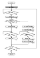
- FIG. 4 is a flowchart showing an example of the flow of operation of the hydraulic excavator 1 under the control of the control unit 60.
- the operator gets into the control unit 41 of the hydraulic excavator 1, sits on the control seat 41a, operates the operation unit 41b (for example, by rotating the ignition key), and starts the engine 40, the monitoring unit 50 starts monitoring the surroundings. (S1).
- the control unit 60 When the monitoring unit 50 detects an obstacle around the hydraulic excavator 1 (Yes in S2), the control unit 60 outputs an alarm from the alarm device 90 (S3).
- the control unit 60 has the display unit 71 functioning as the alarm device 90, along with the bird's-eye view image Bv generated by the monitoring unit 50, the obstacle icons M1, M2, A1, A2, and The position information P1 and P2 are displayed. Further, the control unit 60 controls at least one of the rotary lamp 81, the light emitting unit 82, and the alarm unit 83 as necessary to output an alarm indicating that an obstacle has been detected (for example, a rotary lamp). Rotate, turn on LED, output sound, etc.).
- whether or not to output the alarm to the alarm device 90 can be freely set by the operator operating the input unit 72.
- the control unit 60 can control the display unit 71 to display the bird's-eye view image Bv based on the operation of the input unit 72 by the operator, while not displaying the alarm (icon M1 or the like).
- the control unit 60 determines whether or not the operation mode of the hydraulic excavator 1 is set to the crane mode by operating the input unit 72 (S4).
- the control unit 60 regulates the operation of the hydraulic excavator 1 in order to avoid the danger of the hydraulic excavator 1 colliding with an obstacle while working in the normal mode. Is executed (S5).
- the control unit 60 controls to stop the traveling and turning of the hydraulic excavator 1. More specifically, the control unit 60 outputs a control command for shutting off the pilot pressure corresponding to the predetermined hydraulic actuator AC to the solenoid valve SV. As a result, the predetermined hydraulic actuator AC can be locked to stop the traveling and turning of the hydraulic excavator 1.
- the control unit 60 stops the alarm output by the monitoring unit 50 (S7). For example, the control unit 60 hides the icon M1 and the like on the display unit 71. Then, until the engine 40 is stopped by the operator, that is, until the work by the hydraulic excavator 1 is completed (No in S8), the processing after S2 is repeated, and when the work is completed (Yes in S8). Ends a series of processes.
- the control unit 60 When the execution of the operation regulation is stopped in S9, the control unit 60 notifies the execution stop of the operation regulation by the execution stop notification device 100 (S10). For example, as shown in FIG. 3, the control unit 60 causes the display unit 71 functioning as the execution stop notification device 100 to display the information R indicating the execution stop of the operation restriction on the upper side of the display area of the bird's-eye view image Bv. Further, the control unit 60 controls at least one of the rotary lamp 81, the light emitting unit 82, and the alarm unit 83 as necessary to notify the stop of execution of the operation regulation (for example, rotate the rotary lamp at a low speed). , Blink LED, output buzzer sound, etc.).
- the control unit 60 stops the output of the alarm by the alarm device 90 as in S7. (S12). Then, the control unit 60 stops the notification of the execution stop of the operation regulation by the execution stop notification device 100 (S13). For example, the control unit 60 hides the information R on the display unit 71. After that, the process proceeds to S8, and the same processing as described above is performed.
- the control unit 60 executes the operation regulation based on the monitoring result of the monitoring unit 50, while the operation mode is the specific mode. In this case, the execution of the operation regulation based on the monitoring result of the monitoring unit 50 is stopped (S4, S5, S9).
- the operation mode of the hydraulic excavator 1 is a normal mode (for example, an operation mode for running, turning, excavating, etc.)
- the monitoring unit 50 detects an obstacle
- the operation regulation is executed, and the running of the hydraulic excavator 1, for example, is stopped. do.
- the operation mode of the hydraulic excavator 1 is a specific mode (for example, a crane mode)
- the operation regulation of the hydraulic excavator 1 is not executed even when the monitoring unit 50 detects an obstacle. That is, the operation of the suspension work in the crane mode is not stopped.
- the object In the crane mode, if the operation is stopped while the object is suspended, the object may run wild due to inertial force and collide with an obstacle, which increases the risk.
- the control unit 60 executes the operation restriction when the operation mode is the normal mode, while the operation mode is the specific mode. In addition, the execution of the operation regulation is stopped (S2, S4, S5, S9).
- the operation of the hydraulic excavator 1 is restricted in the normal mode other than the specific mode, so that the danger of the hydraulic excavator 1 colliding with the obstacle can be avoided.
- the specific mode the execution of the operation restriction of the hydraulic excavator 1 is stopped, so that the operation of the hydraulic excavator 1 can be continuously performed.
- the hydraulic excavator 1 can execute an operation for avoiding danger to ensure work safety.
- the construction machine is the hydraulic excavator 1, and the specific mode is the crane mode for suspending the object (S4).
- the hydraulic excavator 1 When the hydraulic excavator 1 is operating in the crane mode, if the operation of the hydraulic excavator 1 is stopped while the object is suspended, the risk of the object shaking and colliding with an obstacle may increase. There is.
- the crane mode the execution of the operation regulation of the hydraulic excavator 1 based on the monitoring result of the monitoring unit 50 is stopped, so that the suspended object collides with the obstacle even if the suspended object shakes. It is possible to enable an operation to avoid this and avoid the danger due to the collision at an early stage.
- the control unit 60 stops the execution of the operation regulation based on the monitoring result of the monitoring unit 50 (S4, S9).
- the control unit 60 recognizes that the operation mode is the specific mode and stops the execution of the operation regulation based on the monitoring result of the monitoring unit 50. You can control it.
- the hydraulic excavator 1 is provided with an alarm device 90.
- the alarm device 90 outputs an alarm regardless of whether the control unit 60 executes or stops the operation restriction, and the operator of the hydraulic excavator 1 operates. Alternatively, it is possible to call attention to the people around and to ensure the safety of work.
- the hydraulic excavator 1 is provided with an execution stop notification device 100.
- an execution stop notification device 100 By notifying the execution stop of the operation restriction by the execution stop notification device 100, it is possible to notify the operator of the hydraulic excavator 1 or a person around him of the fact that the execution of the operation restriction has been stopped and call attention to it.
- the display unit 71 also serves as an alarm device 90 and an execution stop notification device 100, and displays an alarm based on the monitoring result of the monitoring unit 50 in addition to the image acquired by the monitoring unit 50 (S3). , When the execution of the operation regulation is stopped, the information indicating the execution stop is displayed (S10). In this configuration, a plurality of information (photographed image, alarm, information on stopping execution of operation restriction) to be notified to the operator are collectively displayed on one display unit 71. As a result, the operator can easily recognize a plurality of information only by looking at the display unit 71.
- the crane mode has been described as an example as a specific mode for executing the operation regulation of the hydraulic excavator 1, but the specific mode is not limited to the crane mode.
- the specific mode may be a fall prevention mode, and even in this case, the same operation restriction execution / stop control as in the present embodiment can be applied.
- the position of the center of gravity of the hydraulic excavator 1 that changes according to the posture of the hydraulic excavator 1 is calculated from the above rotation angle and the like. Based on the calculation result, an operation for preventing the fall (for example, a winding operation of the boom 31 and the arm 32) is automatically controlled by the control unit 60.
- the fall prevention mode is working, if the fall prevention operation is restricted based on the detection of obstacles by the monitoring unit 50, the entanglement operation of the boom 31 and the arm 32 may be stopped to prevent the fall. This makes it impossible, and there is a risk that the hydraulic excavator 1 will tip over.
- the fall prevention mode is set to a specific mode, and in the fall prevention mode, the execution of the operation regulation based on the monitoring result of the monitoring unit 50 is stopped, so that the operation for the fall prevention can be executed, and the hydraulic excavator 1 can be executed. You can avoid the danger of falling.
- the specific mode is a grapple mode in which work is performed with the grappler. May be good. If the operation regulation is executed based on the detection of obstacles by the monitoring unit 50 while grasping a heavy object with the grappler, the operation of the grappler may stop while grasping the heavy object in the air. be. In this case, a heavy object held by the grappler may fall. Therefore, by setting the grapple mode as a specific mode and stopping the execution of the operation regulation based on the monitoring result of the monitoring unit 50 in the grapple mode, it is possible to put the heavy object grasped by the grappler on the ground. The danger of falling heavy objects can be avoided.
- the present invention can be used for construction machinery such as hydraulic excavators.
Landscapes
- Engineering & Computer Science (AREA)
- Mining & Mineral Resources (AREA)
- Civil Engineering (AREA)
- General Engineering & Computer Science (AREA)
- Structural Engineering (AREA)
- Multimedia (AREA)
- Mechanical Engineering (AREA)
- Human Computer Interaction (AREA)
- Component Parts Of Construction Machinery (AREA)
Abstract
Description
図1は、本実施形態の建設機械の一例である油圧ショベル1の概略の構成を示す側面図である。油圧ショベル1は、下部走行体2と、作業機3と、上部旋回体4と、を備える。
図2は、油圧ショベル1の主要部の構成を模式的に示している。油圧ショベル1は、監視部50と、制御部60と、モニタ装置70と、回転灯81と、発光部82と、発報部83と、をさらに備えている。
監視部50は、油圧ショベル1の周囲の障害物の有無を検出することによって周囲を監視する。なお、上記の障害物には、人、物、動物などの監視対象物が含まれる。つまり、油圧ショベル1は、油圧ショベル1の周囲を監視する監視部50を備える。本実施形態では、監視部50は、油圧ショベル1の周囲の画像を取得することによって、油圧ショベル1の周囲を監視する。より具体的に説明すると、監視部50は以下の構成を有する。
制御部60は、油圧ショベル1の各部の動作を制御する。特に、本実施形態では、制御部60は、油圧ショベル1の動作モードが例えば通常モードであるときに、監視部50の監視結果に基づく油圧ショベル1の動作規制を実行し、油圧ショベル1の動作モードが例えばクレーンモードであるときに、監視部50の監視結果に基づく油圧ショベル1の動作規制の実行を停止する。つまり、油圧ショベル1は、油圧ショベル1の動作モードに応じて、監視部50の監視結果に基づく油圧ショベル1の動作規制の実行を制御する制御部60を備える。このような制御部60は、ECU(Electronic Control Unit)と呼ばれる電子制御ユニットで構成される。上記の動作規制には、例えば、走行等の動作の完全な停止のほか、走行速度の制限(低速化)、エンジン回転数の低下などが含まれる。なお、制御部60の制御による動作の詳細については後述する。
モニタ装置70は、操縦席41aの近傍(例えば斜め前方)に配置され、各種の情報を表示して、操縦席41aに着座したオペレータに必要な情報を提供する。このモニタ装置70は、表示部71と、入力部72と、を有する。なお、モニタ装置70自体が内部にECU(モニタECU)を備え、モニタECUによってモニタ装置70内の各部を制御する構成であっても構わない。
図2で示す回転灯81は、監視部50が障害物を検知したときに回転するランプで構成される。発光部82は、例えば発光ダイオード(LED)で構成され、監視部50が障害物を検知したときに点灯または点滅する。発報部83は、監視部50が障害物を検知したときに音を出力するブザーで構成される。なお、発報部83は、監視部50が障害物を検知したときに音声(電子音)を出力する音声出力部で構成されてもよい。回転灯82のランプの回転、発光部82の点灯(または点滅)、発報部63によるブザー音または音声の出力により、オペレータは監視部50が障害物を検知したことを認識することができる。
次に、油圧ショベル1の油圧回路について、図1および図2に基づいて説明する。油圧ショベル1は、複数の油圧アクチュエータACと、複数の油圧アクチュエータACに圧油を圧送する油圧ポンプP0と、パイロットポンプPPと、を備える。なお、図2では、便宜的に、1つの油圧アクチュエータACに対応する油圧回路を示しているが、他の油圧アクチュエータACについても同様の油圧回路が構成されている。
次に、上記構成の油圧ショベル1の動作について説明する。図4は、制御部60の制御による油圧ショベル1の動作の流れの一例を示すフローチャートである。オペレータが油圧ショベル1の操縦部41に乗り込み、操縦席41aに着座して操作部41bを操作し(例えばイグニションキーを回転させ)、エンジン40をかけると、監視部50による周囲の監視が開始される(S1)。
以上のように、制御部60は、油圧ショベル1の動作モードが特定モード以外の通常モードである場合に、監視部50の監視結果に基づく動作規制を実行する一方、動作モードが特定モードである場合に、監視部50の監視結果に基づく動作規制の実行を停止する(S4、S5、S9)。
以上では、油圧ショベル1の動作規制を実行する特定モードとして、クレーンモードを例に挙げて説明したが、特定モードはクレーンモードには限定されない。例えば、特定モードは転倒防止モードであってもよく、この場合でも、本実施形態と同様の動作規制の実行/停止の制御を適用することができる。
41b 操作部
50 監視部
60 制御部
71 表示部(警報装置、実行停止報知装置)
72 入力部
81 回転灯(警報装置、実行停止報知装置)
82 発光部(警報装置、実行停止報知装置)
83 発報部(警報装置、実行停止報知装置)
90 警報装置
100 実行停止報知装置
Claims (7)
- 建設機械の周囲を監視する監視部と、
前記建設機械の動作モードに応じて、前記監視部の監視結果に基づく前記建設機械の動作規制の実行を制御する制御部と、を備え、
前記制御部は、前記動作モードが特定モード以外の通常モードである場合に、前記監視結果に基づく前記動作規制を実行する一方、前記動作モードが前記特定モードである場合に、前記監視結果に基づく前記動作規制の実行を停止する、建設機械。 - 前記制御部は、前記監視部が前記建設機械の周囲に障害物を検知した場合において、前記動作モードが前記通常モードであるときに、前記動作規制を実行する一方、前記動作モードが前記特定モードであるときに、前記動作規制の実行を停止する、請求項1に記載の建設機械。
- 前記建設機械がショベルであり、
前記特定モードは、対象物の吊り作業を行うクレーンモードである、請求項1または2に記載の建設機械。 - 前記特定モードの設定を受け付ける入力部をさらに備え、
前記制御部は、前記入力部によって前記特定モードの設定を受け付けたときに、前記監視結果に基づく前記動作規制の実行を停止する、請求項1から3のいずれかに記載の建設機械。 - 前記監視部の監視結果に基づいて、警報を出力する警報装置をさらに備える、請求項1から4のいずれかに記載の建設機械。
- 前記制御部が前記監視結果に基づく前記動作規制の実行を停止したときに、前記動作規制の実行停止を報知する実行停止報知装置をさらに備える、請求項5に記載の建設機械。
- 前記監視部は、前記建設機械の周囲の画像を取得することによって、前記建設機械の周囲を監視し、
前記建設機械は、前記監視部で取得された前記画像を表示する表示部を備え、
前記表示部は、前記警報装置および前記実行停止報知装置を兼ねており、前記画像に加えて、前記監視部の監視結果に基づく前記警報を表示し、さらに、前記動作規制の実行が停止されたときに、実行停止を示す情報を表示する、請求項6に記載の建設機械。
Priority Applications (4)
| Application Number | Priority Date | Filing Date | Title |
|---|---|---|---|
| EP21879767.8A EP4227160A4 (en) | 2020-10-12 | 2021-08-31 | CONSTRUCTION EQUIPMENT |
| US18/030,999 US12480284B2 (en) | 2020-10-12 | 2021-08-31 | Construction machine |
| KR1020237010742A KR20230085910A (ko) | 2020-10-12 | 2021-08-31 | 건설 기계 |
| CN202180069537.1A CN116490402A (zh) | 2020-10-12 | 2021-08-31 | 工程机械 |
Applications Claiming Priority (2)
| Application Number | Priority Date | Filing Date | Title |
|---|---|---|---|
| JP2020171620A JP7489287B2 (ja) | 2020-10-12 | 2020-10-12 | 建設機械 |
| JP2020-171620 | 2020-10-12 |
Publications (1)
| Publication Number | Publication Date |
|---|---|
| WO2022080025A1 true WO2022080025A1 (ja) | 2022-04-21 |
Family
ID=81208341
Family Applications (1)
| Application Number | Title | Priority Date | Filing Date |
|---|---|---|---|
| PCT/JP2021/031937 Ceased WO2022080025A1 (ja) | 2020-10-12 | 2021-08-31 | 建設機械 |
Country Status (6)
| Country | Link |
|---|---|
| US (1) | US12480284B2 (ja) |
| EP (1) | EP4227160A4 (ja) |
| JP (2) | JP7489287B2 (ja) |
| KR (1) | KR20230085910A (ja) |
| CN (1) | CN116490402A (ja) |
| WO (1) | WO2022080025A1 (ja) |
Cited By (2)
| Publication number | Priority date | Publication date | Assignee | Title |
|---|---|---|---|---|
| WO2024075670A1 (ja) * | 2022-10-03 | 2024-04-11 | 日立建機株式会社 | 作業機械 |
| EP4606958A4 (en) * | 2022-12-22 | 2026-01-28 | Kobelco Constr Mach Co Ltd | CONTROL SYSTEM AND CONTROL METHOD FOR A WORK MACHINE |
Families Citing this family (3)
| Publication number | Priority date | Publication date | Assignee | Title |
|---|---|---|---|---|
| JP7349880B2 (ja) * | 2019-10-18 | 2023-09-25 | 株式会社小松製作所 | 作業機械の周辺監視システム、作業機械、及び作業機械の周辺監視方法 |
| DE112023005350T5 (de) * | 2022-12-23 | 2025-10-23 | Sumitomo Construction Machinery Co., Ltd. | Bagger |
| WO2024262146A1 (ja) * | 2023-06-23 | 2024-12-26 | 株式会社クボタ | 作業機および作業機の制御方法 |
Citations (4)
| Publication number | Priority date | Publication date | Assignee | Title |
|---|---|---|---|---|
| JP2006257724A (ja) * | 2005-03-16 | 2006-09-28 | Hitachi Constr Mach Co Ltd | 作業機械の安全装置 |
| WO2018008504A1 (ja) | 2016-07-04 | 2018-01-11 | 住友建機株式会社 | ショベル |
| JP2018053605A (ja) * | 2016-09-29 | 2018-04-05 | ヤンマー株式会社 | 建設機械 |
| JP2021088840A (ja) * | 2019-12-03 | 2021-06-10 | 瀧冨工業株式会社 | 制御システム及び建設機械 |
Family Cites Families (9)
| Publication number | Priority date | Publication date | Assignee | Title |
|---|---|---|---|---|
| US9043129B2 (en) * | 2010-10-05 | 2015-05-26 | Deere & Company | Method for governing a speed of an autonomous vehicle |
| JP6729146B2 (ja) * | 2016-08-03 | 2020-07-22 | コベルコ建機株式会社 | 障害物検出装置 |
| WO2018084161A1 (ja) * | 2016-11-01 | 2018-05-11 | 住友建機株式会社 | 作業機械用安全管理システム、管理装置、安全管理方法 |
| CN111148878B (zh) * | 2018-01-10 | 2023-08-04 | 住友建机株式会社 | 挖土机及挖土机的管理系统 |
| WO2019189203A1 (ja) * | 2018-03-26 | 2019-10-03 | 住友建機株式会社 | ショベル |
| WO2020032267A1 (ja) * | 2018-08-10 | 2020-02-13 | 住友建機株式会社 | ショベル |
| JP7217691B2 (ja) * | 2019-10-31 | 2023-02-03 | 日立建機株式会社 | 建設機械 |
| US12202669B2 (en) * | 2021-11-18 | 2025-01-21 | Oshkosh Corporation | Refuse vehicle with advanced driver-assistance system |
| EP4549250A1 (en) * | 2022-06-30 | 2025-05-07 | Kubota Corporation | Work machine |
-
2020
- 2020-10-12 JP JP2020171620A patent/JP7489287B2/ja active Active
-
2021
- 2021-08-31 CN CN202180069537.1A patent/CN116490402A/zh active Pending
- 2021-08-31 KR KR1020237010742A patent/KR20230085910A/ko active Pending
- 2021-08-31 EP EP21879767.8A patent/EP4227160A4/en active Pending
- 2021-08-31 WO PCT/JP2021/031937 patent/WO2022080025A1/ja not_active Ceased
- 2021-08-31 US US18/030,999 patent/US12480284B2/en active Active
-
2024
- 2024-05-13 JP JP2024077737A patent/JP7573133B2/ja active Active
Patent Citations (4)
| Publication number | Priority date | Publication date | Assignee | Title |
|---|---|---|---|---|
| JP2006257724A (ja) * | 2005-03-16 | 2006-09-28 | Hitachi Constr Mach Co Ltd | 作業機械の安全装置 |
| WO2018008504A1 (ja) | 2016-07-04 | 2018-01-11 | 住友建機株式会社 | ショベル |
| JP2018053605A (ja) * | 2016-09-29 | 2018-04-05 | ヤンマー株式会社 | 建設機械 |
| JP2021088840A (ja) * | 2019-12-03 | 2021-06-10 | 瀧冨工業株式会社 | 制御システム及び建設機械 |
Non-Patent Citations (1)
| Title |
|---|
| See also references of EP4227160A4 |
Cited By (2)
| Publication number | Priority date | Publication date | Assignee | Title |
|---|---|---|---|---|
| WO2024075670A1 (ja) * | 2022-10-03 | 2024-04-11 | 日立建機株式会社 | 作業機械 |
| EP4606958A4 (en) * | 2022-12-22 | 2026-01-28 | Kobelco Constr Mach Co Ltd | CONTROL SYSTEM AND CONTROL METHOD FOR A WORK MACHINE |
Also Published As
| Publication number | Publication date |
|---|---|
| KR20230085910A (ko) | 2023-06-14 |
| JP2024105507A (ja) | 2024-08-06 |
| JP2022063380A (ja) | 2022-04-22 |
| EP4227160A4 (en) | 2024-11-27 |
| US20230374756A1 (en) | 2023-11-23 |
| EP4227160A1 (en) | 2023-08-16 |
| US12480284B2 (en) | 2025-11-25 |
| CN116490402A (zh) | 2023-07-25 |
| JP7489287B2 (ja) | 2024-05-23 |
| JP7573133B2 (ja) | 2024-10-24 |
Similar Documents
| Publication | Publication Date | Title |
|---|---|---|
| JP7573133B2 (ja) | 建設機械 | |
| JP7591638B2 (ja) | 作業車両の制御方法 | |
| KR20210152558A (ko) | 작업 기계 및 작업 기계의 제어 시스템 | |
| JP7565183B2 (ja) | 作業車両 | |
| JP2021042548A (ja) | 建設機械 | |
| JP7667050B2 (ja) | 作業機械用制御システム、作業機械、作業機械の制御方法及び作業機械用制御プログラム | |
| JP2020189749A (ja) | 作業機械、作業機械の制御方法 | |
| JP4750970B2 (ja) | クレーン作業兼用油圧ショベル | |
| US12441346B2 (en) | Work vehicle | |
| JP2020159045A (ja) | 建設機械 | |
| JP7837419B2 (ja) | 電動式建設機械の給電システム | |
| CN120359337A (zh) | 工程机械的控制系统及控制方法 | |
| JP2018145604A (ja) | 油圧ショベル | |
| WO2023223842A1 (ja) | 作業機械の安全装置 | |
| JP2022163352A (ja) | 作業機械の制御方法、作業機械用制御プログラム、作業機械用制御システム及び作業機械 | |
| JP2025147261A (ja) | 作業機械の制御方法、作業機械用制御プログラム、作業機械用制御システム及び作業機械 | |
| JP2025147260A (ja) | 作業機械の制御方法、作業機械用制御プログラム、作業機械用制御システム及び作業機械 | |
| JP7763689B2 (ja) | 作業機械用制御システム、作業機械、作業機械の制御方法及び作業機械用制御プログラム | |
| JP2021095739A (ja) | 作業機械 | |
| JP2025133828A (ja) | 作業機械用制御システム、作業機械、作業機械の制御方法及び作業機械用制御プログラム | |
| JP2024141723A (ja) | 旋回式作業機械の制御装置 |
Legal Events
| Date | Code | Title | Description |
|---|---|---|---|
| 121 | Ep: the epo has been informed by wipo that ep was designated in this application |
Ref document number: 21879767 Country of ref document: EP Kind code of ref document: A1 |
|
| WWE | Wipo information: entry into national phase |
Ref document number: 202180069537.1 Country of ref document: CN |
|
| NENP | Non-entry into the national phase |
Ref country code: DE |
|
| ENP | Entry into the national phase |
Ref document number: 2021879767 Country of ref document: EP Effective date: 20230512 |
|
| WWG | Wipo information: grant in national office |
Ref document number: 18030999 Country of ref document: US |