WO2022080308A1 - 通信システム - Google Patents
通信システム Download PDFInfo
- Publication number
- WO2022080308A1 WO2022080308A1 PCT/JP2021/037552 JP2021037552W WO2022080308A1 WO 2022080308 A1 WO2022080308 A1 WO 2022080308A1 JP 2021037552 W JP2021037552 W JP 2021037552W WO 2022080308 A1 WO2022080308 A1 WO 2022080308A1
- Authority
- WO
- WIPO (PCT)
- Prior art keywords
- base station
- information
- positioning
- lmf
- communication
- Prior art date
- Legal status (The legal status is an assumption and is not a legal conclusion. Google has not performed a legal analysis and makes no representation as to the accuracy of the status listed.)
- Ceased
Links
Images


Classifications
-
- H—ELECTRICITY
- H04—ELECTRIC COMMUNICATION TECHNIQUE
- H04W—WIRELESS COMMUNICATION NETWORKS
- H04W64/00—Locating users or terminals or network equipment for network management purposes, e.g. mobility management
-
- H—ELECTRICITY
- H04—ELECTRIC COMMUNICATION TECHNIQUE
- H04W—WIRELESS COMMUNICATION NETWORKS
- H04W88/00—Devices specially adapted for wireless communication networks, e.g. terminals, base stations or access point devices
- H04W88/08—Access point devices
- H04W88/085—Access point devices with remote components
-
- H—ELECTRICITY
- H04—ELECTRIC COMMUNICATION TECHNIQUE
- H04W—WIRELESS COMMUNICATION NETWORKS
- H04W88/00—Devices specially adapted for wireless communication networks, e.g. terminals, base stations or access point devices
- H04W88/18—Service support devices; Network management devices
-
- Y—GENERAL TAGGING OF NEW TECHNOLOGICAL DEVELOPMENTS; GENERAL TAGGING OF CROSS-SECTIONAL TECHNOLOGIES SPANNING OVER SEVERAL SECTIONS OF THE IPC; TECHNICAL SUBJECTS COVERED BY FORMER USPC CROSS-REFERENCE ART COLLECTIONS [XRACs] AND DIGESTS
- Y02—TECHNOLOGIES OR APPLICATIONS FOR MITIGATION OR ADAPTATION AGAINST CLIMATE CHANGE
- Y02D—CLIMATE CHANGE MITIGATION TECHNOLOGIES IN INFORMATION AND COMMUNICATION TECHNOLOGIES [ICT], I.E. INFORMATION AND COMMUNICATION TECHNOLOGIES AIMING AT THE REDUCTION OF THEIR OWN ENERGY USE
- Y02D30/00—Reducing energy consumption in communication networks
- Y02D30/70—Reducing energy consumption in communication networks in wireless communication networks
Definitions
- This disclosure relates to wireless communication technology.
- LTE Long Term Evolution
- network the core network and wireless access network
- SAE System Architecture Evolution
- OFDM Orthogonal Frequency Division Multiplexing
- SC-FDMA Single Carrier Frequency Division Multiple Access
- LTE does not include circuit switching and is only a packet communication method.
- FIG. 1 is an explanatory diagram showing a configuration of a wireless frame used in an LTE communication system.
- one radio frame (Radio frame) is 10 ms.
- the radio frame is divided into 10 equally sized subframes.
- the subframe is divided into two equally sized slots.
- the downlink synchronization signal (Downlink Synchronization Signal) is included in the first and sixth subframes for each wireless frame.
- the synchronization signal includes a first synchronization signal (Primary Synchronization Signal: P-SS) and a second synchronization signal (Secondary Synchronization Signal: S-SS).
- Non-Patent Document 1 The decision regarding the channel configuration in the LTE system in 3GPP is described in Non-Patent Document 1 (Chapter 5). It is assumed that the same channel configuration as the non-CSG cell is used in the CSG (Closed Subscriber Group) cell.
- a physical broadcast channel is a communication terminal device such as a base station device (hereinafter, may be simply referred to as a "base station”) to a mobile terminal device (hereinafter, may be simply referred to as a "mobile terminal”). It is a channel for downlink transmission to (hereinafter, may be simply referred to as a "communication terminal”).
- the BCH transport block is mapped to four subframes in a 40 ms interval. There is no explicit signaling for 40ms timing.
- the Physical Control Format Indicator Channel is a channel for downlink transmission from a base station to a communication terminal.
- the PCFICH notifies the communication terminal of the number of OFDM (Orthogonal Frequency Division Multiplexing) symbols used for PDCCHs from the base station.
- PCFICH is transmitted every subframe.
- the physical downlink control channel is a channel for downlink transmission from the base station to the communication terminal.
- the PDCCH is resource allocation information of a downlink shared channel (Downlink Shared Channel: DL-SCH), which is one of the transport channels described later, and a paging channel (Paging Channel: PCH), which is one of the transport channels described later. ) Resource allocation information and HARQ (Hybrid Automatic Repeat reQuest) information related to DL-SCH are notified.
- PDCCH carries an Uplink Scheduling Grant.
- the PDCCH carries Ack (Acknowledgement) / Nack (Negative Acknowledgement), which is a response signal for uplink transmission.
- the PDCCH is also called an L1 / L2 control signal.
- the physical downlink shared channel is a channel for downlink transmission from the base station to the communication terminal.
- a downlink shared channel (DL-SCH), which is a transport channel, and a PCH, which is a transport channel, are mapped to the PDSCH.
- the physical multicast channel is a channel for downlink transmission from the base station to the communication terminal.
- a multicast channel (Multicast Channel: MCH), which is a transport channel, is mapped to the PMCH.
- the physical uplink control channel is a channel for uplink transmission from a communication terminal to a base station.
- the PUCCH carries Ack / Nack, which is a response signal for downlink transmission.
- PUCCH carries CSI (Channel State Information).
- CSI consists of RI (Rank Indicator), PMI (Precoding Matrix Indicator), and CQI (Channel Quality Indicator) reports.
- RI is rank information of a channel matrix in MIMO.
- PMI is information on the precoding weight matrix used in MIMO.
- CQI is quality information indicating the quality of received data or the quality of communication channels.
- the PUCCH also carries a scheduling request (SR).
- SR scheduling request
- the physical uplink shared channel (PUSCH) is a channel for uplink transmission from a communication terminal to a base station.
- An uplink shared channel (UL-SCH), which is one of the transport channels, is mapped to the PUSCH.
- the physical HARQ indicator channel (Physical Hybrid ARQ Indicator Channel: PHICH) is a channel for downlink transmission from a base station to a communication terminal. PHICH carries Ack / Nack, which is a response signal for uplink transmission.
- the physical random access channel (Physical Random Access Channel: PRACH) is a channel for uplink transmission from a communication terminal to a base station. PRACH carries a random access preamble.
- the downlink reference signal (Reference Signal: RS) is a symbol known as an LTE communication system.
- the following five types of downlink reference signals are defined.
- Data demodulation reference signal (Demodulation Reference Signal: DM-RS) which is a cell-specific reference signal (Cell-specific Reference Signal: CRS), MBSFN reference signal (MBSFN Reference Signal), and UE-specific reference signal (UE-specific Reference Signal).
- Positioning Reference Signal PRS
- CSI-RS Channel State Information Reference Signal
- RSRP reference signal received power
- the uplink reference signal is a well-known symbol as an LTE communication system.
- the following two types of uplink reference signals are defined. It is a data demodulation reference signal (Demodulation Reference Signal: DM-RS) and a sounding reference signal (Sounding Reference Signal: SRS).
- DM-RS Data demodulation Reference Signal
- SRS Sounding Reference Signal
- Non-Patent Document 1 The transport channel described in Non-Patent Document 1 (Chapter 5) will be described.
- the broadcast channel BCH
- BCH is notified to the entire coverage of the base station (cell).
- BCH is mapped to the physical broadcast channel (PBCH).
- HARQ Hybrid ARQ
- the DL-SCH can notify the entire coverage of the base station (cell).
- DL-SCH supports dynamic or quasi-static resource allocation. Quasi-static resource allocation is also called Persistent Scheduling.
- the DL-SCH supports intermittent reception (DRX) of the communication terminal in order to reduce the power consumption of the communication terminal.
- the DL-SCH is mapped to a physical downlink shared channel (PDSCH).
- the paging channel supports the DRX of the communication terminal in order to enable the low power consumption of the communication terminal.
- the PCH is required to notify the entire coverage of the base station (cell).
- the PCH is dynamically mapped to a physical resource such as a physical downlink shared channel (PDSCH) available for traffic.
- PDSCH physical downlink shared channel
- MCH Multicast Channel
- MCH Multicast Channel
- MTCH Multimedia Broadcast Multicast Service
- MCCH Multimedia Broadcast Multicast Service
- MCH supports quasi-static resource allocation.
- the MCH is mapped to the PMCH.
- HARQ Hybrid ARQ
- PUSCH physical uplink shared channel
- Random Access Channel is limited to control information. RACH is at risk of collision.
- the RACH is mapped to a physical random access channel (PRACH).
- PRACH physical random access channel
- HARQ is a technique for improving the communication quality of a transmission line by combining an automatic repeat request (ARQ) and an error correction (Forward Error Correction).
- ARQ automatic repeat request
- FEC Correction Forward Error Correction
- HARQ has an advantage that error correction functions effectively by retransmission even for a transmission line whose communication quality changes. In particular, it is possible to further improve the quality by synthesizing the reception result of the first transmission and the reception result of the retransmission at the time of retransmission.
- the broadcast control channel (Broadcast Control Channel: BCCH) is a downlink channel for broadcast system control information.
- BCCH which is a logical channel, is mapped to a broadcast channel (BCH), which is a transport channel, or a downlink shared channel (DL-SCH).
- BCH broadcast channel
- DL-SCH downlink shared channel
- the paging control channel is a downlink channel for transmitting changes in paging information (Paging Information) and system information (System Information).
- PCCH is used when the network does not know the cell location of the communication terminal.
- the PCCH which is a logical channel, is mapped to a paging channel (PCH), which is a transport channel.
- the shared control channel (Common Control Channel: CCCH) is a channel for transmission control information between the communication terminal and the base station. CCCH is used when the communication terminal does not have an RRC connection with the network.
- CCCH is mapped to the downlink shared channel (DL-SCH), which is a transport channel.
- DL-SCH downlink shared channel
- UL-SCH uplink shared channel
- Multicast Control Channel is a downlink channel for one-to-many transmission.
- the MCCH is used for transmitting MBMS control information for one or several MTCHs from the network to the communication terminal.
- MCCH is used only for communication terminals that are receiving MBMS.
- the MCCH is mapped to a multicast channel (MCH), which is a transport channel.
- the individual control channel (Dedicated Control Channel: DCCH) is a channel for transmitting individual control information between the communication terminal and the network on a one-to-one basis.
- DCCH is used when the communication terminal is an RRC connection.
- the DCCH is mapped to the uplink shared channel (UL-SCH) on the uplink and to the downlink shared channel (DL-SCH) on the downlink.
- the individual traffic channel (Dedicated Traffic Channel: DTCH) is a channel for one-to-one communication to an individual communication terminal for transmitting user information.
- DTCH exists both up and down.
- the DTCH is mapped to the uplink shared channel (UL-SCH) on the uplink and to the downlink shared channel (DL-SCH) on the downlink.
- the multicast traffic channel (Multicast Traffic channel: MTCH) is a downlink channel for transmitting traffic data from the network to the communication terminal.
- MTCH is a channel used only for communication terminals receiving MBMS.
- the MTCH is mapped to a multicast channel (MCH).
- CGI is a Cell Global Identifier.
- ECGI is an E-UTRAN Cell Global Identifier.
- CSG Cell Subscriber Group
- LTE Long Term Evolution Advanced
- UMTS Universal Mobile Telecommunication System
- the position tracking of the communication terminal is performed in units of areas consisting of one or more cells.
- the position tracking is performed to track the position of the communication terminal even in the standby state and to call the communication terminal, in other words, to enable the communication terminal to make a call.
- the area for tracking the position of this communication terminal is called a tracking area.
- LTE-A Long Term Evolution Advanced
- CA Carrier Aggregation
- the UE When CA is configured, the UE, which is a communication terminal, has a network (NW) and only one RRC connection (RRC connection).
- RRC connection In RRC connection, one serving cell provides NAS mobility information and security input. This cell is called a primary cell (PCell).
- PCell In the downlink, the carrier corresponding to the PCell is the downlink primary component carrier (DL PCC).
- DL PCC downlink primary component carrier
- the carrier corresponding to the PCell In the uplink, the carrier corresponding to the PCell is the uplink primary component carrier (UL PCC).
- a secondary cell is configured to form a set of serving cells together with a PCell according to the capability of the UE.
- the carrier corresponding to SCell in the downlink is a downlink secondary component carrier (DL SCC).
- DL SCC downlink secondary component carrier
- UL SCC uplink secondary component carrier
- a set of serving cells consisting of one PCell and one or more SCells is configured for one UE.
- LTE-A new technologies in LTE-A include technology that supports a wider bandwidth (Wider bandwidth extension) and multipoint coordinated transmission / reception (Coordinated Multiple Point transmission and reception: CoMP) technology.
- CoMP being studied for LTE-A in 3GPP is described in Non-Patent Document 1.
- a small eNB (hereinafter sometimes referred to as a "small base station device") constituting a small cell in order to cope with a huge amount of traffic in the future.
- a technique for increasing frequency utilization efficiency and increasing communication capacity by installing a large number of small eNBs and configuring a large number of small cells is being studied.
- DC dual connectivity
- eNBs that perform dual connectivity (DC)
- MeNB master eNB
- SeNB secondary eNB
- the traffic volume of mobile networks is on the rise, and the communication speed is also increasing.
- LTE and LTE-A start full-scale operation, it is expected that the communication speed will be further increased.
- 5G 5th generation
- METIS summarizes 5G requirements (see Non-Patent Document 5).
- the system capacity is 1000 times
- the data transmission speed is 100 times
- the data processing delay is 1/10 (1/10)
- the number of simultaneous connections of communication terminals is 100 times that of the LTE system. As a requirement, it is required to further reduce the power consumption and the cost of the device.
- the NR system is being studied based on the LTE system and LTE-A system, but changes and additions have been made from the LTE system and LTE-A system in the following points.
- OFDM is used in the downlink direction
- OFDM is used in the uplink direction
- DFT-s-OFDM DFT-spread-OFDM
- cell coverage can be ensured by forming a narrow beam-shaped transmission / reception range (beamforming) and changing the direction of the beam (beam sweeping).
- various subcarrier intervals that is, various numerologies are supported.
- one subframe is one millisecond and one slot is composed of 14 symbols, regardless of numerology.
- the number of slots included in one subframe is one in the numerology with a subcarrier interval of 15 kHz, and increases in proportion to the subcarrier interval in other numerologies (Non-Patent Document 13 (3GPP TS38.211). )reference).
- the downlink synchronization signal in NR is transmitted from the base station as a synchronization signal burst (hereinafter, may be referred to as SS burst) in a predetermined cycle and with a predetermined duration.
- the SS burst is composed of a synchronization signal block (Synchronization Signal Block: hereinafter may be referred to as an SS block) for each beam of the base station.
- the base station transmits the SS block of each beam while changing the beam within the duration of the SS burst.
- the SS block is composed of P-SS, S-SS, and PBCH.
- phase Tracking Reference Signal Phase Tracking Reference Signal: PTRS
- PTRS Phase Tracking Reference Signal
- slot configuration notification (Slot Format Indication: SFI) has been added to the information contained in PDCCH in order to flexibly switch DL / UL in the slot.
- BWP Bandwidth Part
- DC is DC by LTE base station and NR base station connected to EPC, DC by NR base station connected to 5G core system, and LTE base station and NR base station connected to 5G core system.
- DC is being considered (see Non-Patent Documents 12, 16 and 19).
- Non-Patent Documents 24 to 27 positioning techniques (see Non-Patent Documents 24 to 27) and integrated access and backhaul (IAB) are being studied (see Non-Patent Documents 16, 28, 29).
- a positioning method (Multi-Round Trip Time: Multi-RTT) using a round-trip delay time between a UE and a plurality of base stations is being studied (see Non-Patent Document 24).
- Non-Patent Documents 16, 28, 29).
- a service (may be an application) using side link (SL: Side Link) communication (also referred to as PC5 communication) is supported in the EPS (Evolved Packet System) described later and in the 5G core system.
- SL Side Link
- EPS Evolved Packet System
- 5G core system See Non-Patent Documents 1, 16, 20, 21, 22, 23.
- V2X Vehicle-to-everything
- proximity service and the like.
- one of the purposes of the present disclosure is to realize a communication system capable of accurately positioning a communication terminal even when a base station moves.
- the communication system includes a base station and a communication terminal connected to the base station, and the base station communicates the reception result of the uplink positioning signal transmitted by the communication terminal and the position information of the own base station. It is transmitted to the positioning performing device, which is a device having a positioning function for deriving the position of the terminal, and the communication terminal transmits the reception result of the downlink positioning signal transmitted by the base station to the positioning performing device.
- the positioning performing device which is a device having a positioning function for deriving the position of the terminal
- the communication terminal transmits the reception result of the downlink positioning signal transmitted by the base station to the positioning performing device.
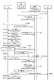
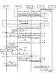
- FIG. 1 is a sequence diagram showing an example of a UE positioning sequence in which a base station notifies the LMF of a combination of a position of its own base station and time information according to the first embodiment.
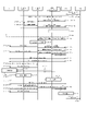
- the first embodiment it is a sequence diagram which showed the other example of the positioning sequence of the UE which notifies the LMF from the combination of the position and time information of the own base station from a base station.
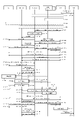
- the first modification of the first embodiment in the UE positioning sequence when the base station has an LMF, an operation of notifying the serving base station of the combination of the position and time information of the own base station from the peripheral base station is performed. It is a sequence diagram which shows.
- the serving base station in the UE positioning sequence when the UE has an LMF, the serving base station notifies the UE of the combination of the position and time information in the own base station and the peripheral base stations. It is a sequence diagram which shows the operation.
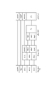
- FIG. 2 is a sequence diagram showing an example of a UE positioning sequence including a process of notifying the position of the own DU from the DU to the CU with respect to the second embodiment.
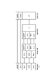
- FIG. 3 is a sequence diagram showing an example of a positioning sequence of an IAB node for the third embodiment. It is a sequence diagram which shows an example of the positioning sequence when the positioning of the IAB node and the UE is performed at the same time about the third embodiment.
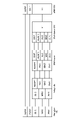
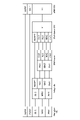
- FIG. 4 is a diagram showing an example of a protocol stack in the case where the CU has an adaptation layer for the fourth embodiment.
- FIG. 4 is a diagram showing an example of a protocol stack in the case where the DU has an adaptation layer for the fourth embodiment.
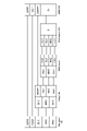
- FIG. 5 is a diagram showing an example of a protocol stack in the case where the BAP is arranged above the adaptation layer for the first modification of the fourth embodiment. It is a figure which shows an example of the protocol stack in the case where the adaptation layer is arranged above BAP about the modification 1 of Embodiment 4.
- FIG. 5 is a diagram showing another example of the protocol stack in the case where the adaptation layer is arranged above the BAP for the modification 1 of the fourth embodiment.
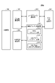
- FIG. 2 is a block diagram showing the overall configuration of the LTE communication system 200 discussed in 3GPP.
- the radio access network is referred to as E-UTRAN (Evolved Universal Terrestrial Radio Access Network) 201.
- the mobile terminal device (hereinafter referred to as "Mobile terminal (User Equipment: UE)") 202, which is a communication terminal device, can wirelessly communicate with the base station device (hereinafter referred to as "base station (E-UTRAN NodeB: eNB)”) 203. Yes, signals are sent and received by wireless communication.
- base station E-UTRAN NodeB: eNB
- the “communication terminal device” includes not only mobile terminal devices such as mobile mobile phone terminal devices but also non-moving devices such as sensors.
- the “communication terminal device” may be simply referred to as a "communication terminal”.
- Control protocols for mobile terminals 202 such as RRC (Radio Resource Control) and user planes (hereinafter sometimes referred to as U-Plane), such as PDCP (Packet Data Convergence Protocol), RLC (Radio Link Control), MAC (Medium). If Access Control) and PHY (Physical layer) are terminated at base station 203, E-UTRAN is composed of one or more base stations 203.
- RRC Radio Resource Control
- U-Plane User Plane
- PDCP Packet Data Convergence Protocol
- RLC Radio Link Control
- MAC Medium
- E-UTRAN is composed of one or more base stations 203.
- the control protocol RRC Radio Resource Control
- the states of the base station 203 and the mobile terminal 202 in the RRC include RRC_IDLE and RRC_CONTECTED.
- RRC_IDLE PLMN (Public Land Mobile Network) selection, system information (System Information: SI) notification, paging (paging), cell re-selection (cell re-selection), mobility, etc. are performed.
- RRC_CONCEPTED the mobile terminal has an RRC connection and can send and receive data to and from the network. Further, in RRC_CONCEPTED, handover (HO), measurement of an adjacent cell (Neighbor cell), and the like are performed.
- Base station 203 is composed of one or more eNBs 207.
- EPC Evolved Packet Core
- EPS Evolved Packet System
- the EPC, which is a core network, and the E-UTRAN201, which is a wireless access network, may be collectively referred to as a "network".
- the eNB 207 is a mobility management Entity (MME), an S-GW (Serving Gateway), or an MME / S-GW unit (hereinafter, may be referred to as “MME unit”) 204 including MME and S-GW. It is connected by the S1 interface, and control information is communicated between the eNB 207 and the MME unit 204.
- MME unit mobility management Entity
- a plurality of MME units 204 may be connected to one eNB 207.
- the eNBs 207 are connected by an X2 interface, and control information is communicated between the eNBs 207s.
- the MME unit 204 controls the connection between the eNB 207, which is a higher-level device, specifically a higher-level node and is a base station, and the mobile terminal (UE) 202.
- the MME unit 204 constitutes an EPC which is a core network.
- Base station 203 constitutes E-UTRAN 201.
- the base station 203 may be configured as one cell or may be configured as a plurality of cells. Each cell has a predetermined range as a coverage that can communicate with the mobile terminal 202, and wirelessly communicates with the mobile terminal 202 within the coverage. When one base station 203 constitutes a plurality of cells, each cell is configured to be communicable with the mobile terminal 202.
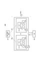
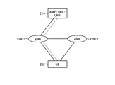
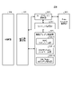
- FIG. 3 is a block diagram showing the overall configuration of the 5G communication system 210 discussed in 3GPP.
- the radio access network is referred to as NG-RAN (Next Generation Radio Access Network) 211.
- the UE 202 can wirelessly communicate with the NR base station apparatus (hereinafter referred to as "NR base station (NG-RAN NodeB: gNB)") 213, and transmits and receives signals by wireless communication.
- NR base station (NG-RAN NodeB: gNB) NR base station
- the core network is also referred to as a 5G core (5G Core: 5GC).
- 5G Core 5G Core
- Control protocols for the UE 202 such as RRC (Radio Resource Control) and user planes (hereinafter sometimes referred to as U-Plane), such as SDAP (Service Data Adaptation Protocol), PDCP (Packet Data Convergence Protocol), RLC (Radio Link). If Control), MAC (Medium Access Control), and PHY (Physical layer) are terminated at NR base station 213, NG-RAN is composed of one or more NR base stations 213.
- RRC Radio Resource Control
- U-Plane user planes
- SDAP Service Data Adaptation Protocol
- PDCP Packet Data Convergence Protocol
- RLC Radio Link
- MAC Medium Access Control
- PHY Physical layer
- the function of the control protocol RRC (Radio Resource Control) between the UE 202 and the NR base station 213 is the same as that of LTE.
- the states of the NR base station 213 and the UE 202 in the RRC include RRC_IDLE, RRC_CONTECTED, and RRC_INACTIVE.
- RRC_IDLE and RRC_CONTECTED are the same as the LTE method.
- RRC_INACTIVE system information (System Information: SI) notification, paging, cell re-selection, mobility, etc. are performed while the connection between the 5G core and the NR base station 213 is maintained. ..
- gNB217 is an access / mobility management function (Access and Mobility Management Function: AMF), a session management function (Session Management Function: SMF), or UPF (User Plane Function), or AMF / SMF / UPF including AMF, SMF, and UPF.
- the unit (hereinafter sometimes referred to as “5GC unit”) 214 is connected to the unit by an NG interface. Control information and / or user data is communicated between the gNB 217 and the 5GC unit 214.
- the NG interface is a general term for the N2 interface between gNB217 and AMF, the N3 interface between gNB217 and UPF, the N11 interface between AMF and SMF, and the N4 interface between UPF and SMF.
- a plurality of 5GC units 214 may be connected to one gNB 217.
- the gNB 217s are connected by an Xn interface, and control information and / or user data are communicated between the gNB 217s.
- the 5GC unit 214 is a higher-level device, specifically, a higher-level node, and distributes a paging signal to one or more base stations 203 and / or base stations 213. Further, the 5GC unit 214 performs mobility control (MobilityControl) in the standby state (Idle State). The 5GC unit 214 manages the tracking area list when the mobile terminal 202 is in the standby state, the inactive state (Inactive State), and the active state (Active State). The 5GC unit 214 starts the paging protocol by transmitting a paging message to a cell belonging to the tracking area (tracking area) in which the mobile terminal 202 is registered.
- MobilityControl mobility control
- the 5GC unit 214 starts the paging protocol by transmitting a paging message to a cell belonging to the tracking area (tracking area) in which the mobile terminal 202 is registered.
- the NR base station 213 may also form one or a plurality of cells like the base station 203. When one NR base station 213 constitutes a plurality of cells, each cell is configured to be communicable with the UE 202.
- the gNB 217 may be divided into a central unit (Central Unit: hereinafter, may be referred to as CU) 218 and a distributed unit (Distributed Unit: hereinafter, may be referred to as DU) 219.
- CU central unit
- DU distributed unit
- One CU218 is configured in gNB217.
- DU219 is composed of one or more in gNB217.
- the CU 218 is connected to the DU 219 by an F1 interface, and control information and / or user data is communicated between the CU 218 and the DU 219.
- the integrated data management (UDM) function and the policy control function (Policy Control Function: PCF) described in Non-Patent Document 21 (3GPP TS23.501) may be included.
- UDM and / or PCF may be included in 5GC section 214 in FIG.
- the location management function (LMF) described in Non-Patent Document 24 (3GPP TS38.305) may be provided.
- the LMF may be connected to the base station via the AMF as disclosed in Non-Patent Document 30 (3GPP TS23.263).
- the non-3GPP interworking function (N3IWF) described in Non-Patent Document 21 (3GPP TS23.501) may be included.
- the N3IWF may terminate the access network (AN) with the UE in non-3GPP access with the UE.
- FIG. 4 is a diagram showing a configuration of DC by eNB and gNB connected to EPC.
- the solid line shows the connection of U-Plane
- the broken line shows the connection of C-Plane.
- eNB223-1 is a master base station
- gNB224-2 is a secondary base station (this DC configuration may be referred to as EN-DC).
- FIG. 4 shows an example in which a U-Plane connection between the MME unit 204 and gNB224-2 is performed via eNB223-1, but even if the U-Plane connection is performed directly between the MME unit 204 and gNB224-2. good.
- FIG. 5 is a diagram showing the configuration of DC by gNB connected to the NG core.
- the solid line shows the connection of U-Plane
- the broken line shows the connection of C-Plane.
- gNB224-1 is a master base station
- gNB224-2 is a secondary base station (this DC configuration may be referred to as NR-DC).
- FIG. 5 shows an example in which the U-Plane connection between the 5GC unit 214 and gNB224-2 is performed via gNB224-1, but even if the U-Plane connection is performed directly between the 5GC unit 214 and gNB224-2. good.
- FIG. 6 is a diagram showing the configuration of DC by eNB and gNB connected to the NG core.
- the solid line shows the connection of U-Plane
- the broken line shows the connection of C-Plane.
- eNB 226-1 is a master base station
- gNB 224-2 is a secondary base station (this DC configuration may be referred to as NG-EN-DC).
- FIG. 6 shows an example in which the U-Plane connection between the 5GC unit 214 and the gNB 224-2 is performed via the eNB 226-1, but even if the U-Plane connection is performed directly between the 5GC unit 214 and the gNB 224-2. good.
- FIG. 7 is a diagram showing other configurations of DC by eNB and gNB connected to the NG core.
- the solid line shows the connection of U-Plane
- the broken line shows the connection of C-Plane.
- gNB224-1 is a master base station
- eNB226-2 is a secondary base station (this DC configuration may be referred to as NE-DC).
- FIG. 7 shows an example in which the U-Plane connection between the 5GC unit 214 and the eNB 226-2 is performed via gNB224-1, but even if the U-Plane connection is performed directly between the 5GC unit 214 and the eNB 226-2. good.
- FIG. 8 is a block diagram showing the configuration of the mobile terminal 202 shown in FIG. The transmission process of the mobile terminal 202 shown in FIG. 8 will be described.
- the control data from the protocol processing unit 301 and the user data from the application unit 302 are stored in the transmission data buffer unit 303.
- the data stored in the transmission data buffer unit 303 is passed to the encoder unit 304 and subjected to encoding processing such as error correction.
- the data encoded by the encoder unit 304 is modulated by the modulation unit 305. Precoding in MIMO may be performed in the modulation unit 305.
- the modulated data is converted into a baseband signal, then output to the frequency conversion unit 306, and converted into a radio transmission frequency. After that, the transmission signal is transmitted from the antennas 307-1 to 307-4 to the base station 203.
- the reception process of the mobile terminal 202 is executed as follows.
- the radio signal from the base station 203 is received by the antennas 307-1 to 307-4.
- the received signal is converted from the radio reception frequency into a baseband signal by the frequency conversion unit 306, and demodulation processing is performed by the demodulation unit 308.
- the demodulation unit 308 may perform weight calculation and multiplication processing.
- the demodulated data is passed to the decoder unit 309, and decoding processing such as error correction is performed.
- the control data is passed to the protocol processing unit 301, and the user data is passed to the application unit 302. A series of processes of the mobile terminal 202 is controlled by the control unit 310. Therefore, although the control unit 310 is omitted in FIG.
- the control unit 310 is realized by, for example, a processing circuit including a processor and a memory. That is, the control unit 310 is realized by the processor executing a program in which a series of processes of the mobile terminal 202 is described. A program in which a series of processes of the mobile terminal 202 is described is stored in a memory. Examples of memory are non-volatile or volatile semiconductor memories such as RAM (Random Access Memory), ROM (Read Only Memory), and flash memory.
- the control unit 310 may be realized by a dedicated processing circuit such as FPGA (Field Programmable Gate Array), ASIC (Application Specific Integrated Circuit), DSP (Digital Signal Processor). In FIG. 8, the number of antennas used by the mobile terminal 202 for transmission and the number of antennas used for reception may be the same or different.
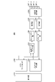
- FIG. 9 is a block diagram showing the configuration of the base station 203 shown in FIG. The transmission process of the base station 203 shown in FIG. 9 will be described.
- the EPC communication unit 401 transmits / receives data between the base station 203 and the EPC (MME unit 204, etc.).
- the 5GC communication unit 412 transmits / receives data between the base station 203 and the 5GC (5GC unit 214, etc.).
- the other base station communication unit 402 transmits / receives data to / from another base station.
- the EPC communication unit 401, 5GC communication unit 412, and other base station communication unit 402 each exchange information with the protocol processing unit 403.
- the control data from the protocol processing unit 403, and the user data and control data from the EPC communication unit 401, 5GC communication unit 412, and the other base station communication unit 402 are stored in the transmission data buffer unit 404.
- the data stored in the transmission data buffer unit 404 is passed to the encoder unit 405 and subjected to encoding processing such as error correction. There may be data directly output from the transmission data buffer unit 404 to the modulation unit 406 without performing the encoding process.
- the encoded data is modulated by the modulation unit 406. Precoding in MIMO may be performed in the modulation unit 406.
- the modulated data is converted into a baseband signal, then output to the frequency conversion unit 407, and converted into a radio transmission frequency. After that, the transmission signal is transmitted from the antennas 408-1 to 408-4 to one or more mobile terminals 202. In FIG. 9, the case where the number of antennas is four is illustrated, but the number of antennas is not limited to four.
- the reception process of the base station 203 is executed as follows.
- a radio signal from one or more mobile terminals 202 is received by the antenna 408.
- the received signal is converted from the radio reception frequency into a baseband signal by the frequency conversion unit 407, and demodulation processing is performed by the demodulation unit 409.
- the demodulated data is passed to the decoder unit 410, and decoding processing such as error correction is performed.
- the control data is passed to the protocol processing unit 403 or 5GC communication unit 412 or EPC communication unit 401 or other base station communication unit 402, and the user data is passed to the 5GC communication unit 412 or EPC communication unit 401 or other base. It is passed to the station communication unit 402.
- a series of processes of the base station 203 is controlled by the control unit 411. Therefore, although the control unit 411 is omitted in FIG. 9, it is connected to each unit 401 to 410, 412.
- the control unit 411 is realized by a processing circuit including a processor and a memory, or a dedicated processing circuit such as an FPGA, an ASIC, or a DSP, similarly to the control unit 310 of the mobile terminal 202 described above.
- the number of antennas used by the base station 203 for transmission and the number of antennas used for reception may be the same or different.
- FIG. 9 is a block diagram showing the configuration of the base station 203, but the base station 213 may have the same configuration. Further, with respect to FIGS. 8 and 9, the number of antennas of the mobile terminal 202 and the number of antennas of the base station 203 may be the same or different.
- FIG. 10 is a block diagram showing the configuration of the MME.
- FIG. 10 shows the configuration of the MME 204a included in the MME unit 204 shown in FIG. 2 described above.
- the PDN GW communication unit 501 transmits / receives data between the MME 204a and the PDN GW (Packet Data Network Gate Way).
- the base station communication unit 502 transmits / receives data by the S1 interface between the MME 204a and the base station 203.
- the data received from the PDN GW is user data
- the user data is passed from the PDN GW communication unit 501 to the base station communication unit 502 via the user plane communication unit 503 and to one or more base stations 203. Will be sent.
- the user data is passed from the base station communication unit 502 to the PDN GW communication unit 501 via the user plane communication unit 503 and transmitted to the PDN GW.
- control data is passed from the PDN GW communication unit 501 to the control plane control unit 505.
- control data is passed from the base station communication unit 502 to the control plane control unit 505.
- the HeNBGW communication unit 504 transmits / receives data between the MME204a and the HeNB GW (Home-eNB Gate Way).
- the control data received by the HeNBGW communication unit 504 from the HeNB GW is passed to the control plane control unit 505.
- the HeNBGW communication unit 504 transmits the control data input from the control plane control unit 505 to the HeNB GW.
- the control plane control unit 505 includes a NAS security unit 505-1, a SAE bearer control unit 505-2, an idle state mobility management unit 505-3, and the like, and is referred to as a control plane (hereinafter referred to as C-Plane). In some cases), perform all processing.
- the NAS security unit 505-1 performs security of NAS (Non-Access Stratum) messages and the like.
- the SAE bearer control unit 505-2 manages the bearers of the SAE (System Architecture Evolution).
- the idle state mobility management unit 505-3 manages the mobility of the standby state (Idle State: LTE-IDLE state, or simply referred to as idle), generates and controls the paging signal in the standby state, and is under the umbrella of the idle state mobility management unit 505-3. Addition, deletion, update, search, tracking area list management, etc. of the tracking area of one or more mobile terminals 202.
- the standby state Idle State: LTE-IDLE state, or simply referred to as idle
- MME204a distributes the paging signal to one or more base stations 203.
- MME204a performs mobility control in the standby state (Idle State).
- the MME204a manages the tracking area list when the mobile terminal 202 is in the standby state and when it is in the active state (Active State).
- the MME204a starts the paging protocol by transmitting a paging message to a cell belonging to the tracking area (tracking area) in which the mobile terminal 202 is registered.
- the management of the CSG of the eNB 207 connected to the MME 204a, the management of the CSG ID, and the management of the whitelist may be performed by the idle state mobility management unit 505-3.
- control unit 506 A series of processes of MME204a is controlled by the control unit 506. Therefore, although the control unit 506 is omitted in FIG. 10, it is connected to each unit 501 to 505.
- the control unit 506 is realized by a processing circuit including a processor and a memory, or a dedicated processing circuit such as an FPGA, an ASIC, or a DSP, similarly to the control unit 310 of the mobile terminal 202 described above.
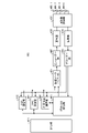
- FIG. 11 is a block diagram showing the configuration of the 5GC unit.
- FIG. 11 shows the configuration of the 5GC unit 214 shown in FIG. 3 described above.
- FIG. 11 shows a case where the 5GC unit 214 shown in FIG. 5 includes an AMF configuration, an SMF configuration, and an UPF configuration.
- the Data Network communication unit 521 transmits / receives data between the 5GC unit 214 and the Data Network.
- the base station communication unit 522 transmits / receives data via the S1 interface between the 5GC unit 214 and the base station 203, and / or the NG interface between the 5GC unit 214 and the base station 213.
- the user data is passed from Data Network communication unit 521 to base station communication unit 522 via user plain communication unit 523, and one or more base stations 203. And / or transmitted to base station 213.
- the user data is passed from the base station communication unit 522 to the Data Network communication unit 521 via the user plain communication unit 523, and is passed to the Data Network communication unit 521. Will be sent to.
- control data When the data received from the Data Network is control data, the control data is passed from the Data Network communication unit 521 to the session management unit 527 via the user plane communication unit 523.
- the session management unit 527 passes the control data to the control plane control unit 525.
- the control data When the data received from the base station 203 and / or the base station 213 is control data, the control data is passed from the base station communication unit 522 to the control plane control unit 525.
- the control plane control unit 525 passes the control data to the session management unit 527.
- the control plane control unit 525 includes a NAS security unit 525-1, a PDU session control unit 525-2, an idle state mobility management unit 525-3, and the like, and may be referred to as a control plane (hereinafter, also referred to as C-Plane). Performs all processing for (is).
- the NAS security unit 525-1 performs security of NAS (Non-Access Stratum) messages and the like.
- the PDU session control unit 525-2 manages the PDU session between the mobile terminal 202 and the 5GC unit 214.
- the idle state mobility management unit 525-3 manages the mobility of the standby state (idle state (Idle State): RRC_IDLE state, or simply also referred to as idle), generates and controls the paging signal in the standby state, and is one under the umbrella. Addition, deletion, update, search, tracking area list management, etc. of the tracking area of one or more mobile terminals 202 are performed.
- a series of processes of the 5GC unit 214 is controlled by the control unit 526. Therefore, although the control unit 526 is omitted in FIG. 11, it is connected to each unit 521 to 523, 525, 527.
- the control unit 526 is realized by a processing circuit including a processor and a memory, or a dedicated processing circuit such as an FPGA, an ASIC, or a DSP, similarly to the control unit 310 of the mobile terminal 202 described above.
- FIG. 12 is a flowchart showing an outline from a cell search to a standby operation performed by a communication terminal (UE) in an LTE communication system.
- the communication terminal starts the cell search, in step ST601, the slot timing and the frame are used by using the first synchronization signal (P-SS) and the second synchronization signal (S-SS) transmitted from the surrounding base stations. Synchronize the timing.
- P-SS first synchronization signal
- S-SS second synchronization signal
- the P-SS and S-SS are collectively called a synchronization signal (SS).
- a synchronization code corresponding to one-to-one is assigned to the PCI assigned to each cell in the synchronization signal (SS).
- the number of PCIs is considered to be 504.
- the communication terminal synchronizes using the 504 ways of PCI, and detects (identifies) the PCI of the synchronized cell.
- the communication terminal then receives a cell-specific reference signal (CRS), which is a reference signal (reference signal: RS) transmitted from the base station for each cell to the synchronized cell in step ST602. ) Is detected, and the received power of RS (Reference Signal Received Power: RSRP) is measured.
- CRS cell-specific reference signal
- RS Reference Signal Received Power
- RS Reference Signal Received Power
- RS Reference Signal Received Power
- step ST603 the communication terminal selects the cell having the highest RS reception quality, for example, the cell having the highest RS reception power, that is, the best cell, from among the one or more cells detected up to step ST602. select.
- the communication terminal receives the best cell PBCH and obtains the BCCH which is the broadcast information.
- a MIB Master Information Block
- the MIB information includes, for example, a DL (downlink) system bandwidth (also called a transmission bandwidth configuration (dl-bandwidth)), the number of transmission antennas, and an SFN (System Frame Number).
- the communication terminal receives the DL-SCH of the cell based on the cell configuration information of the MIB, and obtains the SIB (System Information Block) 1 in the broadcast information BCCH.
- the SIB 1 includes information on access to the cell, information on cell selection, and scheduling information on another SIB (SIBk; an integer of k ⁇ 2). Further, SIB1 includes a tracking area code (Tracking Area Code: TAC).
- the communication terminal compares the TAC of SIB1 received in step ST605 with the TAC portion of the tracking area identifier (Tracking Area Identity: TAI) in the tracking area list already owned by the communication terminal. ..
- the tracking area list is also referred to as a TAI list (TAI list).
- TAI is identification information for identifying a tracking area, and is composed of MCC (Mobile Country Code), MNC (Mobile Network Code), and TAC (Tracking Area Code).
- MCC Mobile Country Code
- MNC Mobile Network Code
- TAC Track Area Code
- MCC Mobile Country Code
- MNC Mobile Network Code
- TAC Track Area Code
- step ST606 if the TAC received in step ST605 is the same as the TAC included in the tracking area list, the communication terminal enters the standby operation in the cell. In comparison, if the TAC received in step ST605 is not included in the tracking area list, the communication terminal passes through the cell to the core network (Core Network, EPC) including the MME and the like, and TAU (Tracking Area Update). Request a change in the tracking area to do this.
- the core network Core Network, EPC
- MME Management Entity
- the best beam may be selected in addition to the best cell in step ST603.
- the beam information for example, the beam identifier may be acquired in step ST604.
- the scheduling information of Remaining Minimum SI may be acquired in step ST604.
- RMSI Remaining Minimum SI
- the device constituting the core network tracks based on the identification number (UE-ID, etc.) of the communication terminal sent from the communication terminal together with the TAU request signal. Update the area list.
- the core network side device transmits the updated tracking area list to the communication terminal.
- the communication terminal rewrites (updates) the TAC list held by the communication terminal based on the received tracking area list. After that, the communication terminal enters the standby operation in the cell.
- the cell composed of eNB has a relatively wide range of coverage.
- cells are configured to cover an area with a relatively wide range of coverage of the plurality of cells composed of the plurality of eNBs.
- the cell composed of eNB has a narrow range of coverage as compared with the coverage of the conventional cell composed of eNB. Therefore, as in the conventional case, in order to cover a certain area, a large number of small-celled eNBs are required as compared with the conventional eNBs.
- macro cells cells having relatively large coverage, such as cells composed of conventional eNBs, are referred to as “macro cells”, and eNBs constituting macro cells are referred to as “macro eNBs”.
- a cell having a relatively small coverage such as a cell made into a small cell, is referred to as a "small cell”, and an eNB constituting the small cell is referred to as a "small eNB”.
- the macro eNB may be, for example, a "Wide Area Base Station" described in Non-Patent Document 7.
- the small eNB may be, for example, a low power node, a local area node, a hotspot, or the like.
- the small eNB is a pico eNB that constitutes a pico cell, a femto eNB that constitutes a femto cell, a HeNB, an RRH (Remote Radio Head), an RRU (Remote Radio Unit), an RRE (Remote Radio Equipment), or an RN (Relay Node).
- the small eNB may be a "Local Area Base Station" or a "Home Base Station" described in Non-Patent Document 7.
- FIG. 13 shows an example of the cell configuration in NR.
- a narrow beam is formed and transmitted in a different direction.
- the base station 750 uses the beam 751-1 to transmit and receive to and from a mobile terminal at a certain time. At other times, the base station 750 uses the beam 751-2 to transmit and receive to and from the mobile terminal.
- the base station 750 uses one or more of the beams 751-3 to 751-8 to transmit and receive to and from the mobile terminal. By doing so, the base station 750 constitutes a wide range of cells.
- FIG. 13 shows an example in which the number of beams used by the base station 750 is 8, but the number of beams may be different from 8. Further, in the example shown in FIG. 13, the number of beams used simultaneously by the base station 750 is set to one, but may be a plurality.
- SL Side Link
- D2D Device to Device
- V2V Vehicle to Vehicle
- the physical channel used for SL (see Non-Patent Document 1) will be described.
- the physical sidelink broadcast channel (PSBCH) carries information related to synchronization with the system and is transmitted from the UE.
- the physical sidelink discovery channel (PSDCH: Physical sidelink discovery channel) carries sidelink discovery messages from the UE.
- the physical sidelink control channel (PSCCH: Physical sidelink control channel) carries control information from the UE for sidelink communication and V2X sidelink communication.
- the physical sidelink shared channel (PSSCH: Physical sidelink shared channel) carries data from the UE for sidelink communication and V2X sidelink communication.
- the physical sidelink feedback channel (PSFCH: Physical sidelink feedback channel) carries HARQ feedback on the sidelink from the UE that received the PSCH transmission to the UE that transmitted the PSCH.
- the transport channel used for SL (see Non-Patent Document 1) will be described.
- the side link broadcast channel (SL-BCH: Sidelink broadcast channel) has a predetermined transport format and is mapped to the PSBCH which is a physical channel.
- the Sidelink Discovery Channel (SL-DCH: Sidelink discovery channel) has a fixed size, periodic notification transmission in a predetermined format.
- SL-DCH also supports both UE automatic resource selection and resource allocation scheduled by eNB. There is a risk of collision in UE automatic resource selection, and there is no collision when the UE allocates individual resources by eNB.
- SL-DCH also supports HARQ combining, but not HARQ feedback.
- SL-DCH is mapped to PSDCH, which is a physical channel.
- SL-SCH Sidelink shared channel
- SL-SCH Sidelink shared channel
- SL-SCH supports broadcast transmission.
- SL-SCH supports both UE automatic resource selection and resource allocation scheduled by eNB. There is a risk of collision in UE automatic resource selection, and there is no collision when the UE allocates individual resources by eNB.
- SL-SCH also supports HARQ combining, but not HARQ feedback.
- the SL-SCH also supports dynamic link adaptation by changing the transmit power, modulation, and coding.
- SL-SCH is mapped to PSSCH which is a physical channel.
- the side link notification control channel (SBCCH: Sidelink Broadcast Control Channel) is a side link channel for transmitting side link system information from one UE to another UE.
- the SBCCH is mapped to the transport channel SL-BCH.
- the side link traffic channel (STCH: Sidelink Traffic Channel) is a one-to-many side link traffic channel for transmitting user information from one UE to another UE.
- STCH is used only by UEs with side-link communication capabilities and UEs with V2X side-link communication capabilities.
- One-to-one communication between UEs with two side-link communication capabilities is also realized in STCH.
- the STCH is mapped to the transport channel SL-SCH.
- the side link control channel (SCCH: Sidelink Control Channel) is a side link control channel for transmitting control information from one UE to another UE.
- the SCCH is mapped to the transport channel SL-SCH.
- V2X communication In 3GPP, it is being considered to support V2X communication even in NR.
- the study of V2X communication in NR is proceeding based on the LTE system and the LTE-A system, but changes and additions from the LTE system and the LTE-A system are made in the following points.
- PC5-S signaling is being studied in order to support unicast and groupcast in addition to broadcast in SL communication (see Non-Patent Document 22 (3GPP TS23.287)).
- PC5-S signaling is performed to establish SL, a link for performing PC5 communication.
- the link is performed on the V2X layer and is also referred to as a layer 2 link.
- RRC signaling in SL communication is also referred to as PC5 RRC signaling.
- PC5 RRC signaling it has been proposed to notify the capabilities of UEs among UEs that perform PC5 communication, and to notify the setting of an AS layer for performing V2X communication using PC5 communication.
- the UE positioning may be performed using positioning signal transmission / reception between the base station and the UE.
- the downlink positioning signal may be, for example, a PRS (Positioning Reference Signal), an SS block, a DM-RS, or a PTRS.
- the upstream positioning signal may be, for example, SRS (Sounding Reference Signal), PRACH, DM-RS, or PTRS.
- the base station may transmit a downlink positioning signal to the UE.
- the UE may transmit an uplink positioning signal to the base station.
- the downlink positioning signal transmission from the base station and the uplink positioning signal transmission from the UE may be performed independently.
- the UE may transmit the uplink positioning signal triggered by the reception of the downlink positioning signal from the base station.
- the base station may transmit the downlink positioning signal triggered by the reception of the uplink positioning signal from the UE.
- the UE may notify the LMF of the downlink positioning signal reception result.
- the reception result of the downlink positioning signal may include, for example, information regarding the propagation delay of the downlink positioning signal, or information regarding the arrival direction of the downlink positioning signal.
- the UE may transmit information to the LMF regarding the time difference between receiving the downlink positioning signal and transmitting the uplink positioning signal, or may transmit information regarding the uplink positioning signal transmission time. Alternatively, information regarding the downlink positioning signal reception time may be transmitted.
- the base station may notify the LMF of the uplink positioning signal reception result.
- the reception result of the uplink positioning signal may include, for example, information regarding the propagation delay of the uplink positioning signal, or information regarding the arrival direction of the uplink positioning signal.
- the base station may notify the LMF of information regarding the downlink positioning signal transmission time, may transmit information regarding the uplink positioning signal reception time, or may receive the uplink positioning signal. Information regarding the time difference between the transmission of the downlink positioning signal and the transmission of the downlink positioning signal may be transmitted.
- the LMF may derive the position of the UE using the above-mentioned information from the UE and / or the base station.
- the base station may be stationary or may be moving.
- the base station notifies the LMF of information regarding the location of its own base station. You may notify the time information. The base station may send the information to the LMF once or multiple times.
- the base station may notify the LMF of information in which the position of the base station and the time information are associated with each other.
- the LMF may use the information to calculate the position of the UE. As a result, for example, since the position of the base station at that time is known, the LMF can accurately calculate the position of the UE.
- the information in (1) above may be, for example, an identifier of a base station.
- the information of the identifier may be, for example, gNB-ID.
- the LMF may use the information to identify the base station from which the notification is made. This allows, for example, the LMF to easily identify the base station that is the source of the notification, and as a result, the positioning procedure in the communication system can be quickly executed.
- the information in (2) above may include, for example, information indicating the position of the base station.
- the information indicating the position of the base station may be, for example, information indicating latitude, longitude, and / or altitude, or information indicating a relative position from a predetermined point. This allows, for example, the LMF to reduce errors in the UE position calculation.
- the information in (2) above may include information on the accuracy of the position of the base station.
- the information regarding accuracy may be provided, for example, regardless of the axis, or may be provided for each axis.
- accuracy may be given for each of latitude, longitude, and altitude, and even if accuracy in the horizontal direction, that is, the latitude / longitude direction and accuracy in the vertical direction, that is, the altitude direction are provided. good. This allows, for example, the LMF to derive accuracy in the UE position calculation.
- the information in (2) above may include, for example, information on the zone disclosed in Non-Patent Document 33 (3GPP TR37.985).
- the information regarding the zone may be one or plural.
- the LMF may use the information to change the base station used for positioning.
- the LMF may use a base station used for UE positioning as a base station belonging to the same zone. As a result, for example, it is possible to prevent the range in which the base station used for positioning exists from being unnecessarily increased, and as a result, it is possible to improve the positioning accuracy.
- the LMF may reassign the zone to the base station by using the information indicating the position of the base station and the information indicating the zone.
- the LMF may notify the base station of the information on the zone after reassignment.
- the base station may use the information to update the information of the zone of its own base station. This makes it possible to reduce interference with other UEs, for example, in side link communication performed by a UE under the base station.
- the information in (3) above may include information on the propagation delay of the positioning signal, information on the accuracy of the propagation delay, and information on the arrival angle of the positioning signal.
- Information on the accuracy of the arrival angle may be included, or information on the plurality of combinations described above may be included. This allows, for example, the LMF to quickly derive the position of the UE.
- the information in (4) above may include, for example, information regarding the time when the position of the base station is derived, information regarding the accuracy of the time, and transmission of a positioning signal to the UE.
- Information on the time accuracy may be included, information on the accuracy of the time may be included, information on the time when the positioning signal is received from the UE may be included, and information on the accuracy of the time. May be included, or information on the plurality of combinations described above may be included.
- the LMF may use the information to derive the position of the UE at a certain time.
- the LMF derives the position of the UE by using a combination of the time when the position of the base station is derived, the time when the positioning signal is transmitted to the UE, and the time when the time when the positioning signal is received from the UE is close to each other. You may. This allows, for example, the LMF to improve the accuracy of UE position derivation.
- the information in (5) above may be, for example, one-dimensional speed of the base station, horizontal speed, vertical speed, latitude, longitude, and / or altitude. It may be a speed in the direction.
- the LMF may use the information to calculate the position of the UE. This allows, for example, the LMF to improve the accuracy of UE position derivation.
- the information in (6) above may be, for example, the absolute value of the acceleration of the base station, the acceleration in each of the horizontal direction and the vertical direction, and the latitude, longitude, and / or altitude direction. It may be acceleration.
- the LMF may use the information to calculate the position of the UE. This allows, for example, the LMF to improve the accuracy of UE position derivation.
- the above-mentioned information (7) may be, for example, information indicating a positioning method using radio waves of a communication system.
- the positioning method may be, for example, OTDOA (Observed Time Difference Of Arrival) or E-CID (Enhanced Cell ID) disclosed in Non-Patent Document 24 (3GPP TS38.305). It may be NR E-CID, or it may be a multi-RTT (Multi-RTT) that uses a round-trip propagation delay time (Round-Trip Time: RTT) between each of the multiple base stations and the UE. It may be DL-AoD (Downlink Angle of Departure), DL-TDOA (Downlink Time Difference Of Arrival), or UL-TDOA (Uplink Time Difference Of Arrival).
- DL-AoD Downlink Angle of Departure
- DL-TDOA Downlink Time Difference Of Arrival
- UL-TDOA Uplink Time Difference Of Arrival
- the above-mentioned information (7) may be positioning using GNSS (Global Navigation Satellite System), positioning using a pressure sensor, or WLAN (Wireless Local Area). Positioning may be performed using Network), positioning may be performed using Bluetooth (registered trademark) (Bluetooth), or positioning may be performed using a terrestrial beacon system (Terrestrial Beacon System). ..
- the LMF may use the information to acquire information about the positioning method of the UE. As a result, for example, the LMF can quickly acquire information on the positioning method of the UE, and as a result, the LMF can quickly perform the positioning of the UE.
- the information in (8) above may be information indicating the validity period of the notification from the base station to the LMF.
- the validity period may be determined, for example, by using the requirements for positioning of the UE (eg, accuracy) or by using the speed of the base station.
- the LMF may use the information to acquire a period during which the information regarding the position of the base station or the like is valid.
- the LMF may request the base station to notify the information such as the position when the valid period has expired.
- the base station may re-notify the LMF when the validity period has expired. This makes it possible to improve the positioning accuracy of the UE, for example.
- the information in (9) above may be information regarding the identifier of the UE to be positioned.
- the information regarding the identifier may be, for example, a UE-ID, or a Subscription Permanent Identifier (SUPI), a Subscription Concealed Identifier (SUCI), or a Permanent Equipment Identifier disclosed in Non-Patent Document 21 (3GPP TS23.501). It may be PEI) and / or 5G Globally Unique Temporary Identifier (5G-GUTI).
- the LMF may use the information to identify the UE. This allows the LMF to quickly identify the UE, for example, even when positioning of a plurality of UEs is performed.
- the above-mentioned information (10) may be, for example, the information obtained by replacing the base station with DU in the above-mentioned (1) to (8).
- the above-mentioned information (10) may be one, or may be included for a plurality of pieces, for example, the number of DUs. This makes it possible to improve the positioning accuracy of the UE even in a communication system using, for example, a base station having a configuration divided into a CU and a DU.
- the above-mentioned information (11) may be, for example, the information obtained by replacing the base station with TRP in the above-mentioned (1) to (8).
- the above-mentioned information (11) may be one, or may be included for a plurality of pieces, for example, the number of TRPs. This makes it possible to improve the positioning accuracy of the UE even in a communication system using, for example, a base station having a TRP.
- the information associated with the position of the base station and the time information may be included in the assistance data notification from gNB to the LMF disclosed in Non-Patent Document 24 (3GPP TS38.305).
- the assistance data notification may include the above-mentioned information (4). This makes it possible to reduce the amount of signaling between the base station and the LMF, for example.
- the information may be included in the notification of uplink information / UE setting data disclosed in Non-Patent Document 24 (3GPP TS38.305).
- the notification may include the information of (2) and (4) described above. As a result, for example, the same effect as described above can be obtained.
- the information may be included in the notification of the positioning signal reception result disclosed in Non-Patent Document 24 (3GPP TS38.305).
- the notification may include the information of (2) and (4) described above.
- the information in (4) may be, for example, information on the time when the position of the base station is acquired. As a result, for example, the same effect as described above can be obtained.
- new signaling may be provided to transmit the information.
- the new signaling may be, for example, TRP information update. This makes it possible to ensure backward compatibility in, for example, a communication system.
- the base station may notify the information associating the position of the own base station with the time information only once.
- a single notification may include only one associated information, or may include a plurality of the associated information.
- the time range included in the plurality of information may include the time for transmitting and receiving the positioning signal.
- the LMF can apply the interpolation processing instead of the extrapolation processing to the derivation of the position of the base station and / or the UE, and as a result, the accuracy of the position calculation can be improved.
- the time range included in the plurality of pieces of the information may not include the time for transmitting and receiving the positioning signal.
- the end point of the range may come before the end point of the time for transmitting and receiving the positioning signal. This makes it possible to reduce, for example, the delay in positioning.
- the base station may notify the information in which the position of the own base station and the time information are associated with each other multiple times.
- the notification may be given a plurality of times, for example, by specifying the number of times or by not specifying the number of times.
- the notification may be given multiple times, for example, periodically.
- Information on the number of times and / or the period may be determined in advance by the standard, may be determined by the LMF, may be determined by the AMF, or may be determined by the base station.
- the LMF and / or AMF may notify the base station of the information.
- the LMF may notify the base station of the information using LPP signaling and / or NRPPa signaling.
- the AMF may notify the base station of the information using NAS signaling.
- the base station may start the periodic notification before the positioning signal transmission / reception, may be started by the positioning signal transmission / reception start instruction from the LMF, or may be triggered by the positioning signal transmission / reception start instruction, or the uplink positioning signal transmission instruction to the UE. You may start later.
- the base station may terminate the periodic notification when the positioning signal transmission / reception with the UE is completed, or may be terminated when the positioning signal transmission / reception result notification to the LMF is triggered. This makes it possible to improve the positioning accuracy of the UE, for example.
- the base station may re-notify the LMF upon the expiration of the validity period of the notification to the LMF, or the position included in the previous notification.
- the notification may be given again when the position of the base station at the present time is separated by a predetermined value or more.
- the predetermined value described above may be determined using, for example, UE positioning requirements (eg, accuracy). This makes it possible to improve the accuracy of UE positioning, for example.
- the base station may give the notification triggered by a predetermined event.
- the base station may give the notification triggered by a positioning signal transmission / reception start instruction from the LMF, may be triggered by an uplink positioning signal transmission instruction to the UE, or may be triggered by a positioning signal transmission / reception with the UE. It may be performed with the completion as a trigger, may be performed with the notification of the positioning signal transmission / reception result to the LMF as a trigger, or may be performed with any one or more of the above. This makes it possible to reduce the amount of signaling between the base station and the LMF, for example.
- the notification of the information from the base station to the LMF may be autonomously sent from the base station to the LMF.
- the base station may give the notification in the wake of a predetermined event.
- the predetermined event may be, for example, reception of a positioning signal transmission / reception start instruction from the LMF, transmission of an uplink positioning signal transmission instruction to the UE, or completion of positioning signal transmission / reception with the UE. It may be the transmission of the positioning signal transmission / reception result notification to the LMF, or may be a plurality of the above. This makes it possible to reduce the amount of signaling between the base station and the LMF, for example.
- the LMF may request the base station to notify the information.
- the base station may notify the LMF of the information in the wake of the request.
- the LMF may request the base station to start notifying the information, or may request the base station to stop notifying the information.
- the base station may start the notification of the information or stop the notification of the information in the wake of the request. This makes it possible, for example, to avoid complexity in communication systems.
- the LMF may request the base station to notify a plurality of the information.
- the notification of the plurality of such information from the base station to the LMF may be performed at one time. This makes it possible to reduce the amount of signaling between the base station and the LMF, for example.
- the notification from the base station to the LMF may be divided into a plurality of times. The notification may be given periodically.
- (F) Information about the number of information included in the notification For example, the number of pieces of information on the combination of the position and time of the base station included in one notification.
- the base station may start the notification to the LMF by using the information regarding (A) described above. This makes it possible, for example, to avoid the design complexity of the process for initiating the notification at the base station.
- the base station may stop the notification to the LMF by using the information regarding (B) described above. This makes it possible to avoid, for example, the complexity of the design regarding the process for stopping the notification in the base station.
- the information shown in (C) above may be, for example, information indicating the range of time information notified from the base station to the LMF.
- the time information may be, for example, the information disclosed as (4) of the information notified by the base station to the LMF described above.
- the information shown in (C) above may include information indicating the start point of the range of the time information, information indicating the end point, and information indicating the period of the range. It may be.
- the base station may use the information shown in (C) above to determine the information to be included in the notification to the LMF. This makes it possible to prevent, for example, the excess or deficiency of information in the notification from the base station to the LMF.
- the information shown in (D) above may include, for example, the cycle of the notification from the base station to the LMF, the information of the offset with respect to the cycle, or both of the above. May be good.
- the offset may be given, for example, as a periodic remainder of the time at which the base station transmits the notification, or may be given with information at a certain transmission time.
- the offset may be given by information using time, or may be given by information using radio frame number, subframe number, slot number, and / or symbol number.
- the base station may use the information to give the notification to the LMF. This allows, for example, the LMF to track changes in the position of the base station, resulting in rapid calculation of the position of the UE.
- the information shown in (E) above may be, for example, once or a plurality of times.
- the value of (E) described above to a small value by the LMF
- the amount of signaling between the base station and the LMF can be reduced.
- the value of (E) described above to a large value by the LMF
- the position of the base station can be calculated with high accuracy, and as a result, the positioning accuracy of the UE position can be improved.
- the information shown in (F) above may be, for example, the number of information regarding the position included in one notification from the base station to the LMF.
- the value of the information may be 1 or 2 or more.
- the amount of processing in the base station can be reduced.
- the position of the base station at a certain time can be calculated with high accuracy, and as a result, the positioning accuracy of the UE position can be improved.
- the information shown in (G) above may include, for example, information regarding a positioning method required by the LMF from the base station.
- the information regarding the positioning method may be, for example, the same as the information disclosed as (7) of the information notified by the base station to the LMF described above. This makes it possible, for example, to improve flexibility in communication systems.
- the information shown in (H) above may be, for example, the information shown in (1) to (12) disclosed as an example of the information notified by the base station to the LMF.
- the base station may derive the information to be notified to the LMF by using the information of (H) described above. As a result, for example, the amount of signaling between the base station and the LMF can be reduced, and the amount of processing in the base station can be reduced.
- the information shown in (I) above may be, for example, information on positioning latency or information on positioning accuracy.
- the base station may, for example, use information about the accuracy of the positioning to determine whether to re-execute the notification to the LMF. For example, when the base station moves by a predetermined value or more from the position at the time of the previous notification, the LMF may be notified again.
- the above-mentioned predetermined value may be determined, for example, by using the accuracy requirement included in the above-mentioned (I). This makes it possible to improve the accuracy of UE positioning, for example.
- the information from the LMF to the base station may be included in the signaling of the assistance data request from the LMF to the gNB (eg, TRP information request) disclosed in Non-Patent Document 24 (3GPP TS38.305). This makes it possible to reduce the amount of signaling between the base station and the LMF, for example.
- the information may be included in the signaling of UL SRS setting request (eg, positioning information request) disclosed in Non-Patent Document 24 (3GPP TS38.305).
- UL SRS setting request eg, positioning information request
- 3GPP TS38.305 3GPP TS38.305
- the information may be included in the signaling of the positioning signal transmission / reception request (eg, Measurement request) disclosed in Non-Patent Document 24 (3GPP TS38.305).
- the positioning signal transmission / reception request eg, Measurement request
- 3GPP TS38.305 3GPP TS38.305
- new signaling may be provided to transmit the information. This makes it possible to ensure backward compatibility in, for example, a communication system.
- FIG. 14 is a sequence diagram showing an example of a UE positioning sequence in which a base station notifies the LMF of a combination of the position and time information of the own base station.
- FIG. 14 shows a case where a multi-RTT is used as the positioning method.
- the base station periodically notifies the LMF of the information of the combination of the position and the time information of the own base station.
- FIG. 14 shows a sequence example when the host device of the base station has a positioning function for deriving the position of the UE, that is, a sequence example when the host device operates as a positioning execution device.
- the AMF requests the LMF for the positioning service.
- the requirement may be, for example, a requirement for measuring the UE position.
- the AMF may make the request triggered by a request from a location service (LCS) client existing outside the 5G system, or may be triggered by a request from a UE, or the AMF spontaneously makes the request. You may go to the target.
- LCS location service
- the request from the LCS, UE, and / or AMF that resides outside the 5G system may include a request for information about the location of the base station to which the UE connects.
- the AMF may request the LMF for information regarding the location of the base station.
- the LCS can quickly grasp the position of the base station to which the UE is connected, and can quickly execute the processing in the location information service.
- the NWDAF Network Data Analytics Function disclosed in Non-Patent Document 21 (3GPP TS23.501) may request the LMF to provide information on the location of the UE and / or the base station.
- the request may be made via AMF.
- the AMF may perform the process of step ST1403 in the wake of the request from the NWDAF.
- it becomes possible to process the position information in the NWDAF and as a result, it becomes possible to reduce the processing amount of other devices in the communication network device.
- downlink PRS setting information is exchanged between the LMF and the serving base station.
- the signaling in procedure 1405 may be, for example, NRPPa signaling.
- the LMF requests TRP information from the serving base station.
- the serving base station notifies the LMF of the TRP information.
- Step ST1409 may include information about the identifier of the cell, DU, and / or TRP (hereinafter, may be referred to as a cell or the like) of the serving base station, or information about the timing of the cell or the like (eg, frame).
- Timing may be included, information regarding PRS settings such as cells may be included, and information regarding SS blocks such as cells, SS bursts (eg, information regarding frequency and / or time resources) may be included. It may include information about the PRS transmission direction from the cell or the like, or may include information about the position of the cell or the like.
- procedure 1410 shown in FIG. 14 the same processing as procedure 1405 is performed between the LMF and the peripheral base station.
- step ST1415 shown in FIG. 14 the serving base station and / or the peripheral base station notifies the LMF of the position and / or time information of the own base station.
- NRPPa signaling may be used for the notification in step ST1415.
- the information transmitted in step ST1415 may include the above-mentioned (1) to (12) disclosed as an example of the information notified by the base station to the LMF.
- the transmission of step ST1415 may be repeated.
- the LMF uses step ST1415 to acquire information about the location of serving base stations and / or peripheral base stations.
- the serving base station and / or the peripheral base station starts the notification of step ST1415 triggered by the procedure 1405 and / or the procedure 1410.
- a capability request and notification regarding positioning are made between the LMF and the UE.
- the signaling in procedure 1420 may be, for example, LPP signaling.
- the LMF requests the UE for capabilities regarding positioning.
- the UE notifies the LMF of the capabilities related to positioning.
- the LMF requests the serving base station for positioning information.
- the request may include a request for setting an uplink positioning signal, for example, an uplink SRS.
- the serving base station determines the uplink SRS resource of the UE.
- the serving base station sets the uplink SRS for the UE.
- the serving base station transmits a response to the positioning information request to the LMF.
- the response may include information about the UE's SRS settings, eg, SRS time and / or frequency resources.
- step ST1436 shown in FIG. 14 the LMF requests the serving base station to activate the SRS transmission of the UE.
- the serving base station requests the UE to activate SRS transmission.
- the UE starts transmission of SRS with step ST1437 as an opportunity.
- the LMF requests the serving base station and / or the peripheral base station to measure the positioning signal.
- NRPPa signaling may be used for the request.
- NRPPa MEASUREMENT REQUEST disclosed in Non-Patent Document 24 (3GPP TS38.305) may be used.
- the LMF notifies the UE of information used for positioning.
- the information may be, for example, information on the downlink PRS of the serving base station and / or the peripheral base station, information on the frame timing, or the combination described above.
- LPP signaling may be used for notification of the information.
- the LPP signaling may be, for example, the LPP Provide Assistance Data disclosed in Non-Patent Document 24 (3GPP TS38.305).
- the LMF requests the UE for positioning.
- LPP signaling may be used for the request.
- the LPP signaling may be, for example, the LPP Request Location Information disclosed in Non-Patent Document 24 (3GPP TS38.305).
- the UE performs PRS measurement processing according to the request.
- step ST1447 shown in FIG. 14 the UE requests the serving base station to set a measurement gap for transmitting and receiving positioning signals.
- RRC signaling for example, RRC Location Measurement Indication disclosed in Non-Patent Document 24 (3GPP TS38.305) may be used.
- the request may include information regarding the initiation of the positioning measurement gap.
- the serving base station instructs the UE to set the measurement gap.
- the UE sets the measurement gap according to the instruction in step ST1449.
- step ST1451 and step ST1453 shown in FIG. 14 the serving base station and the peripheral base station each transmit PRS to the UE.
- step ST1455 the UE performs PRS reception processing from the serving base station and / or the peripheral base station.
- the reception process includes a PRS measurement process.
- step ST1457 shown in FIG. 14 the UE transmits SRS to the serving base station.
- the serving base station processes the reception of SRS from the UE.
- the reception process includes an SRS measurement process.
- step ST1461 shown in FIG. 14 the UE transmits SRS to a peripheral base station.
- the peripheral base station performs SRS reception processing from the UE.
- the reception process includes an SRS measurement process.
- the UE notifies the LMF of information regarding the reception result of the positioning signal.
- LPP signaling may be used for the notification.
- the LPP signaling may be, for example, the LPP Provide Location Information disclosed in Non-Patent Document 24 (3GPP TS38.305).
- the serving base station and / or the peripheral base station notifies the LMF of information regarding the reception result of the positioning signal.
- NRPPa signaling may be used for the notification.
- NRPPa MEASUREMENT RESPONSE disclosed in Non-Patent Document 24 (3GPP TS38.305) may be used.
- the UE requests the serving base station to change the measurement gap.
- the request may be a request to return the measurement gap to the setting before positioning.
- RRC signaling for example, RRC Location Measurement Indication disclosed in Non-Patent Document 24 (3GPP TS38.305) may be used.
- the request may include information about stopping the positioning measurement gap.
- the serving base station instructs the UE to set the measurement gap.
- the UE changes the measurement gap setting according to the instruction in step ST1471.
- step ST1475 shown in FIG. 14 the position and / or time information of the own base station is transmitted from the serving base station and / or the peripheral base station to the LMF.
- the information transmitted in step ST1475 may be the same as in step ST1415.
- the LMF uses step ST1475 to acquire information about the location of serving base stations and / or peripheral base stations.
- the serving base station and / or the peripheral base station may end the periodic transmission shown in step ST1475, triggered by the notification of information regarding the reception result of the positioning signal shown in step ST1467.
- the signaling of step ST1467 transmitted after step ST1467 may be the final transmission process. This makes it possible to reduce the amount of signaling between the base station and the LMF, for example.
- step ST1479 shown in FIG. 14 the LMF calculates the position of the UE.
- Information from step ST1415, step ST1465, step ST1467, and / or step ST1475 may be used to calculate the UE position in the LMF.
- the LMF notifies the AMF of the calculated information regarding the UE position.
- the AMF may notify the UE of the information, may notify the LCS outside the 5G system, or may use the information in its own AMF.
- Step ST1481 shown in FIG. 14 may include information regarding the position and / or time of the base station.
- the AMF may notify the UE of information regarding the position and / or time of the base station, may notify the LCS outside the 5G system, or may be used in the own AMF. This allows, for example, the AMF to appropriately specify RNA and / or tracking areas for moving base stations.
- the LMF may notify the NWDAF of information about the location of the UE and / or the base station.
- the notification may be made via AMF.
- the LMF may give the notification to the NWDAF when the NWDAF requests the information.
- the NWDAF may use the information to perform data processing on location information. This makes it possible to reduce the amount of data processing of other devices in the communication network device, for example.
- FIG. 14 shows an example in which the serving base station and / or the peripheral base station starts the notification of step ST1415 triggered by the procedure 1405 and / or the procedure 1410, but other processing, for example, the positioning signal shown in step ST1440. It may be started with the measurement request of. As a result, for example, the processing of step ST1415 before the measurement request of the positioning signal becomes unnecessary, and as a result, the amount of signaling between the LMF and the base station can be reduced.
- step ST1415 and / or step ST1475 with respect to the LMF by the serving base station and / or the peripheral base station may be performed simultaneously from each base station or may be performed at different timings. By performing at different timings, for example, it becomes possible to level the signaling load in the interface between the LMF and the base station.
- FIG. 15 is a sequence diagram showing another example of the UE positioning sequence in which the base station notifies the LMF of the combination of the position and the time information of the own base station.
- FIG. 15 shows a case where a multi-RTT is used as a positioning method.
- FIG. 15 shows an example in which a base station notifies information on a combination of a position and time information of its own base station, triggered by a request from the LMF.
- the same process as in FIG. 14 is assigned the same step number, and a common description will be omitted.
- Steps ST1403 to ST1437 shown in FIG. 15 are the same as those in FIG.
- the LMF requests the serving base station and / or the peripheral base station for information on the position and / or time of the base station.
- NRPPa signaling may be used for the requirement.
- the request may include the above-mentioned (A) to (J) disclosed as the information included in the request from the LMF to the base station.
- step ST1539 shown in FIG. 15 the serving base station and / or the peripheral base station notifies the LMF of the position and / or time information of the own base station.
- NRPPa signaling may be used for the notification in step ST1539.
- the information transmitted in step ST1539 may include the above-mentioned (1) to (12) disclosed as an example of the information notified by the base station to the LMF.
- the LMF uses step ST1539 to acquire information about the location of serving base stations and / or peripheral base stations.
- Steps ST1440 to ST1471 in FIG. 15 are the same as those in FIG.
- Step ST1573 and step ST1574 in FIG. 15 are the same as step ST1538 and step ST1539, respectively.
- Steps ST1479 to ST1481 in FIG. 15 are the same as those in FIG.
- the UE may notify the LMF of information that combines the downlink positioning signal reception result and the time information.
- the time information may be, for example, information on the time when the UE receives the downlink positioning signal.
- the UE may transmit a plurality of the combined information.
- the notification may be made via the base station and / or AMF.
- the LMF may use the information to derive the location of the UE. This makes it possible to improve the positioning accuracy of the UE, for example.
- the LMF may calculate the position of the UE using the combination of the information notified from the base station. For example, the LMF may calculate the position of the base station at the time when the positioning signal is transmitted and received between the UE and the base station. The LMF may use information about the speed of the base station or information about the acceleration of the base station to calculate the position of the base station. As another example, the LMF may determine the speed and / or acceleration of the base station. The LMF may calculate the position of the UE using the information about the base station position, velocity, and / or acceleration calculated above. This makes it possible to improve the accuracy of UE position calculation, for example.
- the LMF may notify the AMF of the calculation result of the UE position.
- the AMF may notify the information to a device having a location service function.
- the device may be, for example, a UE or a device existing in a network outside the 5G network. This enables processing using UE position information, for example, in a system including a communication system.
- the base station may perform signaling to the LMF via the AMF.
- the LMF may signal to the base station via the AMF. This makes it possible to avoid complexity in the interface between the base station and the LMF, for example.
- the first embodiment it is possible to improve the positioning accuracy of the UE when the base station moves.
- the positioning method of the UE when the LMF is present in the 5GC has been described, but when the base station has the LMF, the method disclosed in the first embodiment may be used.
- the LMF possessed by the serving base station may acquire information regarding the position and time of the own base station.
- the peripheral base station may notify the serving base station of information regarding the position and time of the own base station.
- FIG. 16 is a sequence diagram showing an operation of notifying a serving base station of a combination of a position of its own base station and time information from a peripheral base station in a UE positioning sequence when the base station has an LMF.
- FIG. 16 shows a case where a multi-RTT is used as the positioning method.
- FIG. 16 shows a sequence example when the base station has a positioning function for deriving the position of the UE, that is, a sequence example when the base station operates as a positioning execution device.
- the peripheral base station periodically notifies the serving base station of the information.
- the same process as in FIG. 14 is assigned the same step number, and the details of the process will be omitted.
- the process of the same step number as in FIG. 14 is a process in which the LMF in each step of FIG. 14 is replaced with a serving base station.
- the UE may perform step ST1403.
- the UE may request a positioning service from the serving base station. This makes it possible to quickly execute a request for a positioning service to a serving base station having an LMF, for example.
- the UE may notify the AMF that the process of step ST1403 has been performed.
- the serving base station may give the notification to the AMF.
- the AMF can grasp that the positioning service request has been made to the LMF, and as a result, it is possible to prevent the positioning service from being duplicated.
- the serving base station may perform step ST1481 to the UE.
- the operation may be performed, for example, when the UE makes a request for a positioning service.
- a serving base station having an LMF can quickly notify the UE of the positioning result.
- the serving base station may notify the AMF that the process of step ST1481 has been performed. This makes it possible for the AMF, for example, to know that the positioning has been completed. As a result, it is possible to prevent the occurrence of unnecessary processing waiting time in the processing related to positioning.
- the peripheral base station may notify the serving base station of the combination of the position and time information of the own base station, triggered by a request from the serving base station. For example, in step ST1538, step ST1539, step ST1573, and step ST1574 in FIG. 15, the process of replacing LMF with a serving base station may be performed. This makes it possible to reduce the amount of signaling between the serving base station and the peripheral base station, for example.
- the position of the base station at a certain time can be calculated, and as a result, the positioning accuracy of the UE can be improved.
- Modification example of the first embodiment 2 In the above-described first embodiment, the positioning method of the UE when the LMF is present in the 5GC has been described, but when the UE has the LMF, the method disclosed in the first embodiment may be used.
- the LMF possessed by the UE may acquire information regarding the positions and times of serving base stations and / or peripheral base stations.
- the peripheral base station may notify the UE of information regarding the position and time of the own base station via the serving base station.
- the serving base station may notify the UE of the information of its own base station and / or its peripheral base stations.
- FIG. 17 is a sequence diagram showing an operation in which a serving base station notifies a UE of a combination of position and time information in its own base station and peripheral base stations in a UE positioning sequence when the UE has an LMF. be.
- FIG. 17 shows a case where a multi-RTT is used as the positioning method.
- FIG. 17 shows a sequence example when the UE has a positioning function for deriving the position of the UE, that is, a sequence example when the UE operates as a positioning execution device.
- the serving base station periodically notifies the UE of the information.
- the same process as in FIG. 14 is assigned the same step number, and the details of the process will be omitted.
- the process of the same step number as in FIG. 14 is a process in which the LMF in each step of FIG. 14 is replaced with a UE.
- step ST1714 shown in FIG. 17 the peripheral base station notifies the serving base station of the position and / or time information of the own base station.
- NRPPa signaling may be used for the notification in step ST1714.
- the information transmitted in step ST1714 may include the above-mentioned (1) to (12) disclosed as an example of the information notified by the base station to the LMF.
- the transmission of step ST1714 may be repeated.
- step ST1715 shown in FIG. 17 the serving base station notifies the UE of the position and / or time information of the own base station and / or the peripheral base station.
- NRPPa signaling may be used for the notification in step ST1715.
- the information transmitted in step ST1715 may include the above-mentioned (1) to (12) disclosed as an example of the information notified by the base station to the LMF.
- Step ST1715 may be repeated.
- the transmission of step ST1715 may be performed with step ST1714 as an opportunity, or may be performed independently of step ST1714.
- Step ST1774 and step ST1775 shown in FIG. 17 are the same as step ST1714 and step ST1715, respectively.
- step ST1403 may be performed inside the UE.
- the UE may not transmit step ST1403 to other devices.
- the operation may be performed, for example, when the UE makes a request for a positioning service. This allows, for example, the UE to quickly execute a request for a positioning service from its own UE having an LMF.
- the UE may notify the AMF that the process of step ST1403 has been performed. As a result, for example, the AMF can grasp that the positioning service request has been made to the LMF, and as a result, it is possible to prevent the positioning service from being duplicated.
- the UE may perform step ST1481 with respect to the inside of the own UE.
- the UE may not transmit step ST1481 to other devices.
- the operation may be performed, for example, when the UE makes a request for a positioning service.
- a UE having an LMF can quickly notify its own UE of the positioning result.
- the UE may notify the AMF that the process of step ST1481 has been performed. This makes it possible for the AMF, for example, to know that the positioning has been completed. As a result, it is possible to prevent the occurrence of unnecessary processing waiting time in the processing related to positioning.
- the notification of the combination of the position and time information of the own base station and / or the peripheral base station from the peripheral base station to the serving base station and / or from the serving base station to the UE triggers a request from the UE.
- the peripheral base station may notify the serving base station of the combination of the position and time information of the own base station and / or the peripheral base station, triggered by a request from the UE.
- the UE may request the serving base station to notify the combination.
- the serving base station may request the peripheral base stations to notify the combination.
- the peripheral base station may notify the combination of its own base station in response to a request from the serving base station.
- the serving base station may notify the UE of the combination of its own base station and / or the peripheral base station, triggered by the notification from the peripheral base station. This makes it possible to reduce, for example, the amount of signaling between the UE and the serving base station, and between the serving base station and the peripheral base station.
- the position of the base station at a certain time can be calculated, and as a result, the positioning accuracy of the UE can be improved.
- the 5G base station can be divided into a central unit (CU) and a distributed unit (DU).
- CU central unit
- DU distributed unit
- UE positioning signals may be transmitted and received between the UE and the DU.
- the CU may notify the LMF of information about the location of the DU.
- the CU needs to know the position of the DU.
- the method for the CU to acquire the position of the DU is not disclosed in the standards and the like that have been established so far, including the above-mentioned Non-Patent Documents 1 to 33. Therefore, for example, when the DU moves, the CU cannot grasp the position of the DU, and there arises a problem that the accuracy in the positioning of the UE deteriorates or the positioning becomes impossible.
- the DU notifies the CU of information regarding the position of the own DU.
- the information may include information about time information.
- the time information may be, for example, information related to the time when the DU acquired the position information of the own DU.
- the notification from the DU to the CU may be made using F1 signaling.
- the F1 signaling may be, for example, the signaling of the F1 setup request (F1 SETUP REQUEST) described in Non-Patent Document 31 (3GPP TS38.473), or the signaling of the DU setting update (GNB-DU CONFIGUTATION UPDATE). There may be. This makes it possible to reduce the number of signalings from the DU to the CU, for example. As another example, new F1 signaling may be provided. This eliminates the need to modify existing F1 signaling, for example, and as a result, avoids complexity in the design of communication systems.
- the notification may be performed using RRC signaling.
- RRC signaling for example, in a base station where access / backhaul integration (Integrated Access and Backhaul) (see Non-Patent Document 16 (3GPP TS38.300)) is performed, the notification may be performed using RRC signaling.
- the RRC signaling for the notification may be provided, or the notification may be encapsulated in the RRC signaling and transmitted.
- the notification may be performed using F1 interface signaling encapsulated in RRC signaling, or LPP signaling using RRC signaling and / or NRPPa signaling. This enables, for example, the notification from the DU to the CU even when the CU and the DU are wirelessly connected.
- the notification may be performed by LPP signaling or may be performed by using NRPPa signaling.
- it may be performed using the TRP information response (TRP INFORMATION RESPONSE) disclosed in Non-Patent Document 24 (3GPP TS38.305).
- the CU may transfer the information to the LMF.
- the DU may terminate the LPP protocol or the NRPPa protocol. This makes it possible, for example, to quickly notify the LMF of information about the location of the DU.
- the information regarding (a) described above may be, for example, an identifier of DU.
- the identifier may be, for example, a DU-ID.
- the CU may use the information to identify the DU of the notification source. This allows, for example, the CU to easily identify the DU base station that is the source of the notification, and as a result, the positioning procedure in the communication system can be quickly executed.
- the above-mentioned information regarding (b) may be the same information as (2) disclosed as an example of the information notified by the base station to the LMF in the first embodiment.
- the information may include information about the position of the DU, or may include information about the accuracy of the position of the DU. This allows, for example, the LMF to derive accuracy in the UE position calculation.
- the above-mentioned information regarding (c) may be the same information as (4) disclosed as an example of the information notified by the base station to the LMF in the first embodiment.
- information regarding the time from which the position of the DU is derived may be included, or information regarding the accuracy of the time may be included.
- the LMF may use the information to derive the position of the UE at a certain time. This allows, for example, the LMF to improve the accuracy of UE position derivation.
- the above-mentioned information regarding (d) may be the same information as (7) disclosed as an example of the information notified by the base station to the LMF in the first embodiment.
- the LMF may use the information to acquire information about the positioning method of the UE. As a result, for example, the LMF can quickly acquire information on the positioning method of the UE, and as a result, the LMF can quickly perform the positioning of the UE.
- the above-mentioned information regarding (e) may be, for example, the information obtained by replacing DU with TRP in the above-mentioned (a) to (c).
- the above-mentioned information (e) may be one, or may be included for a plurality of pieces, for example, the number of TRPs. This makes it possible to improve the positioning accuracy of the UE even in a communication system using, for example, a base station having a TRP.
- the CU may request the DU to notify the DU of information regarding the location of the DU.
- the request may be made by F1 signaling, RRC signaling, LPP signaling, or NRPPa signaling.
- F1 signaling RRC signaling
- LPP signaling LPP signaling
- NRPPa signaling NRPPa signaling.
- TRP INFORMATION REQUEST TRP INFORMATION REQUEST
- the CU may terminate the LPP protocol or the NRPPa protocol. This makes it possible, for example, to quickly notify the LMF of information about the location of the DU.
- FIG. 18 is a sequence diagram showing an example of a UE positioning sequence including a process of notifying the position of the own DU from the DU to the CU.
- FIG. 18 shows a case where a multi-RTT is used as the positioning method.
- the same processing as in FIG. 14 is assigned the same step number, and a common description is omitted.
- the process of the same step number as in FIG. 14 is a process in which the base station in each step of FIG. 14 is replaced with CU.
- Step ST1407 shown in FIG. 18 is the same as in FIG.
- the CU requests the DU to provide information regarding the position of the DU.
- the CU is the CU of the serving base station (serving gNB-CU)
- the DU is the DU of the serving base station (serving gNB-DU).
- the request may be made by F1 signaling, RRC signaling, LPP signaling, or NRPPa signaling.
- it may be performed using the TRP information request (TRP INFORMATION REQUEST) disclosed in Non-Patent Document 24 (3GPP TS38.305), or may be performed using a new signaling.
- step ST1808 shown in FIG. 18 the DU notifies the CU of information regarding the position of the own DU.
- the information may include the above-mentioned information (a) to (f) disclosed as an example of the information used for the notification from the DU to the CU.
- the signaling in step ST1808 may be performed using F1 signaling, RRC signaling, LPP signaling, or NRPPa signaling.
- Step ST1409 shown in FIG. 18 is the same as in FIG.
- step ST1851 shown in FIG. 18 the DU transmits the PRS to the UE.
- step ST1857 shown in FIG. 18 the UE transmits SRS to the DU.
- step ST1859 the DU performs the measurement process of SRS.
- the DU notifies the CU of information regarding the measurement result of the upstream SRS.
- the CU may include the notification of the information received in step ST1866 in the measurement result notification to the LMF shown in step ST1467.
- the CU may also notify the information regarding the position of the DU received in the above step ST1808.
- the sequence shown in FIG. 18 may be applied to the case where the peripheral base station has a configuration divided into CU and DU.
- the DU of the peripheral base station may perform the process of step ST1808. This makes it possible to measure the position of the DU of the serving base station even when the peripheral base station is divided into a CU and a DU, for example.
- a plurality of DUs of serving base stations may be used.
- some DUs may be used for signaling, data, and / or positioning signals to and from the UE, and other DUs may send and receive positioning signals to and from the UE.
- the peripheral base station may or may not be used for positioning.
- the accuracy of UE positioning can be improved.
- the amount of signaling between the base station and the LMF can be reduced.
- the method disclosed in this embodiment may be used for notification of information regarding the position of the TRP.
- the DU may notify the CU of information about the location of the TRP under its control.
- the information may include information about the time.
- the CU may transfer the information to the LMF.
- the LMF may use the information to calculate the position of the TRP. This makes it possible to improve the accuracy of UE positioning even in positioning using a base station having a TRP, for example.
- the second embodiment it is possible to notify the information regarding the position of the own DU from the DU to the CU, and as a result, it is possible to improve the accuracy of UE positioning in the LMF.
- the host device has the LMF
- the base station may have the LMF
- the UE may have the LMF
- the 5G base station can support Integrated Access and Backhaul (IAB) (see Non-Patent Document 16 (3GPP TS38.300)). That is, UE positioning may be performed using a base station that supports IAB (hereinafter, may be referred to as an IAB base station).
- IAB base station a base station that supports IAB
- how positioning is performed using an IAB base station is not disclosed in the standards and the like that have been formulated so far, including the above-mentioned Non-Patent Documents 1 to 33. Therefore, there arises a problem that positioning using the IAB base station cannot be performed.
- an IAB node (a base station operating as an IAB node) notifies an IAB donor CU (CU of a base station operating as an IAB donor) of information regarding the position of its own node.
- the notification may be made via the IAB parent node and / or the IAB donor DU.
- F1 signaling may be used for the notification.
- the notification using F1 signaling and the notification method disclosed in the second embodiment may be used in combination.
- the same I / F can be used regardless of whether the communication path between the CU and the DU is wired or wireless, and as a result, complexity in the communication system can be avoided. It becomes.
- the F1 signaling may be encapsulated in RRC signaling, or may be encapsulated in signaling in the BAP (Backhaul Adaptation Protocol) sublayer disclosed in Non-Patent Document 16 (3GPP TS38.300).
- BAP Backhaul Adaptation Protocol
- RRC signaling may be used for the notification.
- the existing RRC signaling may be used, or the RRC signaling used for notifying information about the position of the own node may be provided.
- the IAB node can quickly notify the IAB donor CU of the position of its own node.
- the information contained in the notification from the IAB node to the IAB donor CU is the above information (a) to (f) used for the notification from the DU to the CU disclosed in the second embodiment, and the DU is sent to the IAB node. It may be read as a new one.
- the same I / F can be used regardless of whether the communication path between the CU and the DU is wired or wireless, and as a result, complexity in the communication system can be avoided. It becomes.
- Positioning of the IAB node may be performed.
- the positioning may be performed using, for example, transmission / reception of a positioning signal between the IAB node and the IAB donor DU, or between the IAB node and a peripheral base station.
- Positioning of the IAB node by transmitting and receiving a positioning signal may be performed by using, for example, the method disclosed in Non-Patent Document 24 (3GPP TS38.305), or a modification of Embodiment 1 to Embodiment 1. It may be performed using the method disclosed in Example 2.
- the UE may be read as an IAB node.
- the method disclosed in the first embodiment to the second modification of the first embodiment may be used, for example, when the IAB donor DU moves.
- the position of the IAB donor DU at a certain time can be calculated with high accuracy, and as a result, the accuracy of the position calculation of the IAB node can be improved.
- the IAB node may be able to terminate NAS signaling, LPP signaling, or NRPPa signaling. This enables, for example, transmission / reception using LPP signaling and / or NRPPa signaling between the LMF and the IAB node, and as a result, positioning of the IAB node becomes possible.
- FIG. 19 is a sequence diagram showing an example of the positioning sequence of the IAB node.
- FIG. 19 shows a case where a multi-RTT is used as a positioning method.
- the same processing as in FIG. 14 is assigned the same number, and the details of the processing will be omitted.
- the procedure number and step number processing similar to those in FIG. 14 is a process in which the serving base station is replaced with an IAB donor for each procedure and each step in FIG.
- the UE positioning using the IAB node may be performed.
- the positioning may be performed using, for example, transmission / reception of a positioning signal between the UE and an IAB node, or between the UE and a peripheral base station.
- the positioning may be performed, for example, by using a method in which the modification 2 of the first to the first embodiments and the second embodiment are combined.
- IAB node positioning and UE positioning may be performed separately.
- UE positioning may be performed after IAB node positioning.
- the positioning sequence shown in FIG. 19 and the positioning sequence shown in FIG. 14 may be used in combination. This makes it possible to avoid complexity in the positioning process of the UE, for example.
- Positioning of the IAB node and UE may be performed at the same time.
- the positioning may be performed using, for example, transmission / reception of a positioning signal between the UE and the IAB node, the UE and the peripheral base station, the IAB node and the IAB donor DU, and the IAB node and the peripheral base station.
- the positioning method may be performed by combining the methods disclosed in the second embodiment of the first embodiment to the second embodiment, the second embodiment, and the third embodiment. For example, the sequences shown in FIGS. 14, 18 and 19 may be used in combination. This makes it possible to reduce the latency in positioning, for example.
- FIG. 20 is a sequence diagram showing an example of a positioning sequence when positioning of an IAB node and a UE is performed at the same time.
- FIG. 20 shows a case where a multi-RTT is used as a positioning method.
- the same processes as those in FIGS. 14, 18, and 19 are assigned the same numbers, and the details of the processes will be omitted.
- the IAB donor may determine the necessity of positioning the IAB node. For example, the CU of the IAB donor may determine.
- the IAB donor may make the determination, for example, triggered by the signaling of the TRP information request (TRP INFORMATION REQUEST) from the LMF, the determination may be triggered by the signaling of the SRS setting request, or the LMF.
- the determination may be made in the wake of a request for information regarding the position and time from the IAB donor (see the first embodiment), or the IAB donor may make an autonomous determination.
- the determination at the IAB node may be made, for example, using information about the position change of the IAB node, or is included in the information about positioning requirements, eg, the request from the LMF to the base station in embodiment 1. It may be performed using the information of (I) disclosed as information.
- the IAB donor may notify the LMF of information regarding the necessity of positioning the IAB node.
- the notification may be included in, for example, a TRP information response (TRP INFORMATION RESPONSE) to the LMF, or a new signaling may be provided for the notification.
- TRP INFORMATION RESPONSE TRP INFORMATION RESPONSE
- the LMF may use the information to start positioning the IAB node or may not perform positioning of the IAB node. By not performing the positioning of the IAB node, for example, it is not necessary to perform unnecessary IAB node positioning, and as a result, the latency can be reduced and the amount of signaling in the communication system can be reduced.
- the IAB node may terminate the LPP protocol with the LMF or may terminate the NRPPa protocol. This makes it possible, for example, to quickly notify the LMF of information about the IAB node location.
- the positioning of the UE using the IAB base station becomes possible.
- the base station may notify other base stations of information regarding the position of its own base station, information regarding time, or the above-mentioned. Information about the combination may be notified.
- the peripheral base station may notify the serving base station of information regarding the position and / or time of the own base station.
- the serving base station may notify the LMF of the information about its own base station and / or the information about peripheral base stations. This makes it possible to reduce the amount of signaling between the base station and the LMF, for example.
- the serving base station may request information about the location and / or time of the base station from the peripheral base stations.
- the peripheral base station may notify the serving base station of information regarding the position and / or time of the own base station, triggered by the request. This makes it possible to reduce unnecessary signaling between base stations, for example.
- Embodiment 4 In SL communication, communication between the UE and the NW via a relay has been proposed (see Non-Patent Documents 20 (3GPP TR23.703) and 23 (3GPP TS23.303)).
- the relay between the UE and the NW may be referred to as a UE-to-NW relay or a UE-NW relay.
- a UE that performs a relay between a UE and a NW may be referred to as a relay UE.
- a method using a UE-NW relay can be considered.
- communication between the gNB and the UE is performed via the relay UE.
- communication between the gNB and the relay UE is performed by Uu, and communication between the relay UE and the remote UE is performed by PC5.
- Non-Patent Documents 1 to 33 standards that have been established so far, including the above-mentioned Non-Patent Documents 1 to 33, for devices that should have an adaptation layer when a side link relay is used in a CU-DU separation base station. Etc. are not disclosed. This causes, for example, the problem that the inter-operability when the CU and the DU are provided by different vendors is not guaranteed, and the relay using the side link does not operate in the above-mentioned case.
- the CU has an adaptation layer.
- the DU has no adaptation layer.
- the PDU of the adaptation layer is transmitted and received.
- the PDU of the adaptation layer may be RLC SDU. This makes it possible to reduce the circuit scale of the DU, for example.
- FIG. 21 is a diagram showing an example of a protocol stack between a remote UE, a relay UE, a base station DU (gNB-DU), and a base station CU (gNB-CU) when the CU has an adaptation layer.
- the protocol stack in FIG. 21 shows U-plane data.
- a case where the remote UE does not have an adaptation layer is shown.
- the adaptation (ADAPT) layer is terminated between the relay UE and the gNB-CU.
- the PDCP layer is terminated between the remote UE and the gNB-CU.
- the protocol stack below the PDCP layer may be the same as the U plane. This makes it possible, for example, to avoid the complexity of communication systems.
- FIG. 21 shows a case where the remote UE does not have an adaptation layer, it may have an adaptation layer.
- the adaptation layer may be terminated between the remote UE and the relay UE, and between the relay UE and the gNB-CU, respectively. This makes it possible, for example, to improve flexibility in communication systems.
- the DU has an adaptation layer.
- the CU has no adaptation layer.
- the SDU of the adaptation layer is transmitted and received.
- the SDU of the adaptation layer may be PDCP PDU. This makes it possible to reduce the processing amount of CU, for example.
- FIG. 22 is a diagram showing an example of a protocol stack between a remote UE, a relay UE, a base station DU (gNB-DU), and a base station CU (gNB-CU) when the DU has an adaptation layer.
- the protocol stack of FIG. 22 shows U-plane data. In the example shown in FIG. 22, a case where the remote UE does not have an adaptation layer is shown.
- the adaptation layer is terminated between the relay UE and the gNB-DU.
- the PDCP layer is terminated between the remote UE and the gNB-CU.
- the same may be applied to C-plane.
- the protocol stack below the PDCP layer may be the same as the U plane. This makes it possible, for example, to avoid the complexity of communication systems.
- FIG. 22 shows a case where the remote UE does not have an adaptation layer, it may have an adaptation layer.
- the adaptation layer may be terminated between the remote UE and the relay UE, and between the relay UE and the gNB-DU, respectively. This makes it possible, for example, to improve flexibility in communication systems.
- inter-operability is possible when the CU and the DU are provided by different vendors.
- the following problems occur. That is, since the protocol stack including the BAP and the adaptation layer of the side link is not disclosed, there arises a problem that the side link relay using the IAB base station cannot be executed.
- the BAP is arranged above the adaptation layer of the side link.
- the adaptation layer may be terminated between the relay UE and the IAB node, and between the IAB node and the IAB donor DU, respectively. This makes it possible, for example, to improve flexibility in communication systems.
- FIG. 23 is a diagram showing an example of a protocol stack between a remote UE, a relay UE, an IAB node, an IAB donor DU, and an IAB donor CU (gNB-CU) when the BAP is placed above the adaptation layer.
- the protocol stack in FIG. 23 shows U-plane data.
- a case where the remote UE does not have an adaptation layer is shown.
- the adaptation layer is terminated between the relay UE and the IAB node, and the IAB node and the IAB donor DU, respectively.
- the BAP is terminated between the IAB node and the IAB donor DU.
- U-plane Although the case of U-plane is shown in FIG. 23, the same may be applied to C-plane.
- the protocol stack below the PDCP layer may be the same as the U plane. This makes it possible, for example, to avoid the complexity of communication systems.
- FIG. 23 shows the case where the remote UE does not have an adaptation layer, it may have an adaptation layer.
- the adaptation layer may be terminated between the remote UE and the relay UE, the relay UE and the IAB node, and the IAB node and the IAB donor DU, respectively. This makes it possible, for example, to improve flexibility in communication systems.
- a plurality of IAB nodes may be connected.
- a plurality of IAB nodes may be connected in a column.
- the protocol stack between the plurality of IAB nodes may be the same as the protocol stack between the IAB node and the IAB donor DU. This makes it possible, for example, to improve flexibility in communication systems.
- the IAB node may not perform the protocol processing of the adaptation layer. This makes it possible to reduce the circuit scale in the IAB node, for example.
- the IAB donor CU may perform the processing of the adaptation layer. This makes it possible to reduce the circuit scale of the IAB donor DU, for example.
- FIG. 24 is a diagram showing an example of a protocol stack between a remote UE, a relay UE, an IAB node, an IAB donor DU, and an IAB donor CU (gNB-CU) when the adaptation layer is placed above the BAP. ..
- FIG. 24 shows the case where the IAB donor CU has an adaptation layer.
- the protocol stack of FIG. 24 shows U-plane data. In the example shown in FIG. 24, a case where the remote UE does not have an adaptation layer is shown.
- the adaptation layer is terminated between the relay UE and the IAB donor CU.
- the BAP is terminated between the IAB node and the IAB donor DU.
- the same may be applied to C-plane.
- the protocol stack below the PDCP layer may be the same as the U plane. This makes it possible, for example, to avoid the complexity of communication systems.
- the remote UE may have an adaptation layer.
- the adaptation layer may be terminated between the remote UE and the relay UE, the relay UE and the IAB node, and the IAB node and the IAB donor DU, respectively. This makes it possible, for example, to improve flexibility in communication systems.
- a plurality of IAB nodes may be connected.
- a plurality of IAB nodes may be connected in a column.
- the protocol stack between the plurality of IAB nodes may be the same as the protocol stack between the IAB node and the IAB donor DU. This makes it possible, for example, to improve flexibility in communication systems.
- the IAB donor DU may process the adaptation layer. This makes it possible to reduce the amount of processing of the IAB donor CU, for example.
- FIG. 25 shows another example of a protocol stack between a remote UE, a relay UE, an IAB node, an IAB donor DU, and an IAB donor CU (gNB-CU) when the adaptation layer is placed above the BAP.
- Is. FIG. 25 shows the case where the IAB donor DU has an adaptation layer.
- the protocol stack of FIG. 25 shows U-plane data. In the example shown in FIG. 25, a case where the remote UE does not have an adaptation layer is shown.
- the adaptation layer is terminated between the relay UE and the IAB donor DU, respectively.
- the BAP is terminated between the IAB node and the IAB donor DU.
- U-plane Although the case of U-plane is shown in FIG. 25, the same may be applied to C-plane.
- the protocol stack below the PDCP layer may be the same as the U plane. This makes it possible, for example, to avoid the complexity of communication systems.
- the remote UE may have an adaptation layer.
- the adaptation layer may be terminated between the remote UE and the relay UE, the relay UE and the IAB node, and the IAB node and the IAB donor DU, respectively. This makes it possible, for example, to improve flexibility in communication systems.
- a plurality of IAB nodes may be connected.
- a plurality of IAB nodes may be connected in a column.
- the protocol stack between the plurality of IAB nodes may be such that the PHY, MAC, RLC, and BAP are terminated from each other. This makes it possible, for example, to improve flexibility in communication systems.
- An adaptation layer is used between the relay UE and the IAB node, and a BAP is used between the IAB nodes and between the IAB node and the IAB donor DU.
- a BAP is used between the IAB nodes and between the IAB node and the IAB donor DU.
- only the IAB node directly connected to the relay UE may perform the processing of the adaptation layer.
- FIG. 26 shows the remote UE, relay UE, and IAB node when an adaptation layer is used between the relay UE and the IAB node, and a BAP is used between the IAB node and between the IAB node and the IAB donor DU.
- FIG. 5 shows an example of a protocol stack between an IAB donor DU and an IAB donor CU (gNB-CU).
- the protocol stack of FIG. 26 shows U-plane data. In the example shown in FIG. 26, a case where the remote UE does not have an adaptation layer is shown.
- the adaptation layer is terminated between the relay UE and the IAB node.
- the BAP is terminated between the IAB node and the IAB donor DU.
- Neither the IAB donor DU nor the IAB donor CU has an adaptation layer.
- U-plane Although the case of U-plane is shown in FIG. 26, the same may be applied to C-plane.
- the protocol stack below the PDCP layer may be the same as the U plane. This makes it possible, for example, to avoid the complexity of communication systems.
- FIG. 26 shows a case where the remote UE does not have an adaptation layer, it may have an adaptation layer.
- the adaptation layer may be terminated between the remote UE and the relay UE, and between the relay UE and the IAB node, respectively. This makes it possible, for example, to improve flexibility in communication systems.
- a plurality of IAB nodes may be connected.
- a plurality of IAB nodes may be connected in a column.
- the protocol stack between the plurality of IAB nodes may be such that the PHY, MAC, RLC, and BAP are terminated from each other. This makes it possible, for example, to improve flexibility in communication systems.
- relaying using a side link can be executed in an IAB base station.
- the UE in which the service data is generated is referred to as UE-TX.
- UE-TX when UE-TX is UE1 and UE-RX is UE2, service data is generated in UE2, and when data is transmitted to UE1, UE2 is set to UE-TX and UE1 is set to UE-.
- the method of the present disclosure may be applied as RX. This makes it possible to obtain the same effect.
- the subframe is an example of a communication time unit in the 5th generation communication system.
- the subframe may be a scheduling unit.
- the processing described as a subframe unit may be performed as a TTI unit, a slot unit, a subslot unit, or a minislot unit.
- the method disclosed in each of the above-described embodiments and modifications thereof may be applied not only to the V2X (Vehicle-to-everything) service but also to a service in which SL communication is used.
- V2X Vehicle-to-everything
- SL communication used in various services such as proximity-based service, public safety, wearable terminal-to-device communication, and device-to-device communication in factories.
- 200, 210 communication system 202 communication terminal device (communication terminal), 203,207,213,217,223-1,224-1,224-2,226-1,226-2,750 base station device (base station) ), 204 MME / S-GW part (MME part), 204a MME, 214 AMF / SMF / UPF part (5GC part), 218 central unit, 219 distributed unit, 301, 403 protocol processing part, 302 application part, 303, 404 Transmission data buffer section, 304,405 encoder section, 305,406 modulation section, 306,407 frequency conversion section, 307-1 to 307-4, 408-1 to 408-4 antenna, 308,409 demodulation section, 309, 410 decoder unit, 310,411,506,526 control unit, 401 EPC communication unit, 402 other base station communication unit, 412 5GC communication unit, 501 PDN GW communication unit, 502,522 base station communication unit, 503,523 user plain Communication unit, 504 HeNBGW communication unit
Landscapes
- Engineering & Computer Science (AREA)
- Computer Networks & Wireless Communication (AREA)
- Signal Processing (AREA)
- Mobile Radio Communication Systems (AREA)
Abstract
Description
図2は、3GPPにおいて議論されているLTE方式の通信システム200の全体的な構成を示すブロック図である。図2について説明する。無線アクセスネットワークは、E-UTRAN(Evolved Universal Terrestrial Radio Access Network)201と称される。通信端末装置である移動端末装置(以下「移動端末(User Equipment:UE)」という)202は、基地局装置(以下「基地局(E-UTRAN NodeB:eNB)」という)203と無線通信可能であり、無線通信で信号の送受信を行う。
上記の実施の形態1では、5GCにLMFが存在する場合のUEの測位方法について説明したが、LMFを基地局が有する場合において、実施の形態1において開示した方法が用いられてもよい。サービング基地局が有するLMFは、自基地局の位置および時刻に関する情報を取得してもよい。周辺基地局はサービング基地局に対し、自基地局の位置および時刻に関する情報を通知してもよい。
上記の実施の形態1では、5GCにLMFが存在する場合のUEの測位方法について説明したが、LMFをUEが有する場合において、実施の形態1において開示した方法が用いられてもよい。UEが有するLMFは、サービング基地局および/あるいは周辺基地局の位置および時刻に関する情報を取得してもよい。周辺基地局はUEに対し、サービング基地局経由で自基地局の位置および時刻に関する情報を通知してもよい。サービング基地局はUEに対し、自基地局および/あるいは周辺基地局の該情報を通知してもよい。
5G方式の基地局は、上述したように、中央ユニット(CU)と分散ユニット(DU)とに分割された構成とすることが可能である。本実施の形態では、CUとDUが分離した構成を有する基地局を用いて、UEの測位が行われる場合について説明する。該測位において、UEとDUとの間で測位信号が送受信されてもよい。CUはLMFに対して、DUの位置に関する情報を通知してもよい。
5G方式の基地局は、アクセス・バックホール統合(Integrated Access and Backhaul:IAB)(非特許文献16(3GPP TS38.300)参照)をサポート可能である。すなわち、IABをサポートするする基地局(以下、IAB基地局と称する場合がある)を用いて、UEの測位が行われてもよい。ところが、IAB基地局を用いた測位がどのように行われるかが、上記の非特許文献1~非特許文献33をはじめとする、これまでに策定済みの規格等では開示されていない。そのため、IAB基地局を用いた測位を実行できないという問題が生じる。
SL通信においては、リレー(relay)を介したUEとNWとの間の通信が提案されている(非特許文献20(3GPP TR23.703)、23(3GPP TS23.303)参照)。UEとNWとの間のリレーを、UE-to-NWリレー、あるいは、UE-NW間リレーと称する場合がある。本開示では、UEとNWとの間のリレーを実施するUEを、リレーUEと称する場合がある。
IAB基地局において、サイドリンクを用いた中継(Sidelink Relay)を行おうとすると、以下の問題が生じる。すなわち、BAPと、サイドリンクのアダプテーションレイヤを含んだプロトコルスタックが開示されていないため、IAB基地局を用いたサイドリンク中継を実行できないという問題が生じる。
Claims (4)
- 基地局と、
前記基地局に接続する通信端末と、
を備え、
前記基地局は、前記通信端末が送信する上り測位信号の受信結果と自基地局の位置情報とを、前記通信端末の位置を導出する測位機能を有する装置である測位実施装置へ送信し、
前記通信端末は、前記基地局が送信する下り測位信号の受信結果を前記測位実施装置へ送信する、
ことを特徴とする通信システム。 - 前記基地局は、自基地局の前記位置情報を導出した時刻の情報を該位置情報と対応付けて前記測位実施装置へ送信する、
ことを特徴とする請求項1に記載の通信システム。 - 前記基地局は中央ユニットと1つ以上の分散ユニットとで構成され、
前記位置情報は前記分散ユニットのそれぞれの位置を示す、
ことを特徴とする請求項1または2に記載の通信システム。 - アクセス・バックホール統合をサポート可能な基地局を含んで構成される通信システムであって、
前記アクセス・バックホール統合のドナーとして動作する第1の基地局は、前記アクセス・バックホール統合のノードとして動作する第2の基地局が送信する測位信号の受信結果と自基地局の位置情報とを、前記第2の基地局の位置を導出する測位機能を有する装置である測位実施装置へ送信し、
前記第2の基地局は、前記第1の基地局が送信する測位信号の受信結果を前記測位実施装置へ送信する、
ことを特徴とする通信システム。
Priority Applications (5)
| Application Number | Priority Date | Filing Date | Title |
|---|---|---|---|
| CN202180066278.7A CN116250373A (zh) | 2020-10-13 | 2021-10-11 | 通信系统 |
| JP2022556965A JP7778082B2 (ja) | 2020-10-13 | 2021-10-11 | 通信システム |
| US18/246,201 US20230354250A1 (en) | 2020-10-13 | 2021-10-11 | Communication system |
| EP21880047.2A EP4231733A4 (en) | 2020-10-13 | 2021-10-11 | COMMUNICATION SYSTEM |
| JP2025198253A JP2026041782A (ja) | 2020-10-13 | 2025-11-19 | 通信システム |
Applications Claiming Priority (2)
| Application Number | Priority Date | Filing Date | Title |
|---|---|---|---|
| JP2020-172714 | 2020-10-13 | ||
| JP2020172714 | 2020-10-13 |
Related Child Applications (2)
| Application Number | Title | Priority Date | Filing Date |
|---|---|---|---|
| US18/246,201 A-371-Of-International US20230354250A1 (en) | 2020-10-13 | 2021-10-11 | Communication system |
| US19/408,234 Continuation US20260122605A1 (en) | 2020-10-13 | 2025-12-03 | Communication system |
Publications (1)
| Publication Number | Publication Date |
|---|---|
| WO2022080308A1 true WO2022080308A1 (ja) | 2022-04-21 |
Family
ID=81209119
Family Applications (1)
| Application Number | Title | Priority Date | Filing Date |
|---|---|---|---|
| PCT/JP2021/037552 Ceased WO2022080308A1 (ja) | 2020-10-13 | 2021-10-11 | 通信システム |
Country Status (5)
| Country | Link |
|---|---|
| US (1) | US20230354250A1 (ja) |
| EP (1) | EP4231733A4 (ja) |
| JP (2) | JP7778082B2 (ja) |
| CN (1) | CN116250373A (ja) |
| WO (1) | WO2022080308A1 (ja) |
Cited By (2)
| Publication number | Priority date | Publication date | Assignee | Title |
|---|---|---|---|---|
| WO2024029422A1 (ja) * | 2022-08-03 | 2024-02-08 | 三菱電機株式会社 | 通信システム |
| WO2025033518A1 (ja) * | 2023-08-09 | 2025-02-13 | 京セラ株式会社 | 通信制御方法 |
Families Citing this family (2)
| Publication number | Priority date | Publication date | Assignee | Title |
|---|---|---|---|---|
| WO2022151256A1 (zh) * | 2021-01-14 | 2022-07-21 | Oppo广东移动通信有限公司 | 无线通信的方法、终端设备和网络设备 |
| US12143959B2 (en) * | 2021-08-19 | 2024-11-12 | Qualcomm Incorporated | Acquiring location information of an assisting transmission and reception point (TRP) |
Family Cites Families (1)
| Publication number | Priority date | Publication date | Assignee | Title |
|---|---|---|---|---|
| US11134361B2 (en) * | 2019-02-14 | 2021-09-28 | Qualcomm Incorporated | Systems and architectures for support of high-performance location in a Next Generation Radio Access Network |
-
2021
- 2021-10-11 US US18/246,201 patent/US20230354250A1/en active Pending
- 2021-10-11 CN CN202180066278.7A patent/CN116250373A/zh active Pending
- 2021-10-11 JP JP2022556965A patent/JP7778082B2/ja active Active
- 2021-10-11 WO PCT/JP2021/037552 patent/WO2022080308A1/ja not_active Ceased
- 2021-10-11 EP EP21880047.2A patent/EP4231733A4/en active Pending
-
2025
- 2025-11-19 JP JP2025198253A patent/JP2026041782A/ja active Pending
Non-Patent Citations (34)
| Title |
|---|
| "3rd Generation Partnership Project; Technical Specification Group Radio Access Network; NG Radio Access Network (NG-RAN); Stage 2 functional specification of User Equipment (UE) positioning in NG-RAN (Release 16)", 3GPP STANDARD; TECHNICAL SPECIFICATION; 3GPP TS 38.305, 3RD GENERATION PARTNERSHIP PROJECT (3GPP), MOBILE COMPETENCE CENTRE ; 650, ROUTE DES LUCIOLES ; F-06921 SOPHIA-ANTIPOLIS CEDEX ; FRANCE, vol. RAN WG2, no. V16.2.0, 2 October 2020 (2020-10-02), Mobile Competence Centre ; 650, route des Lucioles ; F-06921 Sophia-Antipolis Cedex ; France , pages 1 - 117, XP051961363 * |
| 3GPP R1-2004492 |
| 3GPP R2-2008254 |
| 3GPP RP-172115 |
| 3GPP RP-200928 |
| 3GPP RP-201293 |
| 3GPP S1-083461 |
| 3GPP TR23.703 |
| 3GPP TR23.799 |
| 3GPP TR36.814 |
| 3GPP TR36.912 |
| 3GPP TR37.985 |
| 3GPP TR38.801 |
| 3GPP TR38.802 |
| 3GPP TR38.804 |
| 3GPP TR38.912 |
| 3GPP TS23.263 |
| 3GPP TS23.287 |
| 3GPP TS23.303 |
| 3GPP TS23.501 |
| 3GPP TS36.300 |
| 3GPP TS37.340 |
| 3GPP TS37.355 |
| 3GPP TS38.211 |
| 3GPP TS38.212 |
| 3GPP TS38.213 |
| 3GPP TS38.214 |
| 3GPP TS38.300 |
| 3GPP TS38.305 |
| 3GPP TS38.321 |
| 3GPP TS38.331 |
| 3GPP TS38.401 |
| 3GPP TS38.473 |
| See also references of EP4231733A4 |
Cited By (2)
| Publication number | Priority date | Publication date | Assignee | Title |
|---|---|---|---|---|
| WO2024029422A1 (ja) * | 2022-08-03 | 2024-02-08 | 三菱電機株式会社 | 通信システム |
| WO2025033518A1 (ja) * | 2023-08-09 | 2025-02-13 | 京セラ株式会社 | 通信制御方法 |
Also Published As
| Publication number | Publication date |
|---|---|
| JP7778082B2 (ja) | 2025-12-01 |
| EP4231733A1 (en) | 2023-08-23 |
| US20230354250A1 (en) | 2023-11-02 |
| JPWO2022080308A1 (ja) | 2022-04-21 |
| EP4231733A4 (en) | 2025-01-22 |
| CN116250373A (zh) | 2023-06-09 |
| JP2026041782A (ja) | 2026-03-10 |
Similar Documents
| Publication | Publication Date | Title |
|---|---|---|
| CN118354427A (zh) | 通信系统、基站和上位装置 | |
| US12471054B2 (en) | Communication system and base station | |
| EP4255057A1 (en) | Communication terminal and communication system | |
| JP7778082B2 (ja) | 通信システム | |
| EP4319429A1 (en) | Communication system and base station | |
| EP4195866A1 (en) | Communication system and communication terminal | |
| CN119545521A (zh) | 通信系统、通信终端及网络 | |
| EP4301045A1 (en) | Communication system and base station | |
| EP4301004A1 (en) | Communication system and communication terminal | |
| WO2022113875A1 (ja) | 通信システムおよび通信端末 | |
| JPWO2020022389A1 (ja) | 通信システム、基地局および通信端末 | |
| JPWO2020054642A1 (ja) | 通信システム、通信端末および基地局 | |
| EP4351191A1 (en) | Communication system and base station | |
| EP4568375A1 (en) | Communication system | |
| EP4440161A1 (en) | Communication system | |
| US20250097790A1 (en) | Communication system | |
| US20260122605A1 (en) | Communication system | |
| EP4440233A1 (en) | Communication system | |
| EP4412309A1 (en) | Communication system |
Legal Events
| Date | Code | Title | Description |
|---|---|---|---|
| 121 | Ep: the epo has been informed by wipo that ep was designated in this application |
Ref document number: 21880047 Country of ref document: EP Kind code of ref document: A1 |
|
| ENP | Entry into the national phase |
Ref document number: 2022556965 Country of ref document: JP Kind code of ref document: A |
|
| WWE | Wipo information: entry into national phase |
Ref document number: 202347016246 Country of ref document: IN |
|
| NENP | Non-entry into the national phase |
Ref country code: DE |
|
| ENP | Entry into the national phase |
Ref document number: 2021880047 Country of ref document: EP Effective date: 20230515 |