WO2022085100A1 - 空調制御装置 - Google Patents
空調制御装置 Download PDFInfo
- Publication number
- WO2022085100A1 WO2022085100A1 PCT/JP2020/039495 JP2020039495W WO2022085100A1 WO 2022085100 A1 WO2022085100 A1 WO 2022085100A1 JP 2020039495 W JP2020039495 W JP 2020039495W WO 2022085100 A1 WO2022085100 A1 WO 2022085100A1
- Authority
- WO
- WIPO (PCT)
- Prior art keywords
- analysis
- airflow
- unit
- air conditioner
- condition
- Prior art date
- Legal status (The legal status is an assumption and is not a legal conclusion. Google has not performed a legal analysis and makes no representation as to the accuracy of the status listed.)
- Ceased
Links
Images





Classifications
-
- F—MECHANICAL ENGINEERING; LIGHTING; HEATING; WEAPONS; BLASTING
- F24—HEATING; RANGES; VENTILATING
- F24F—AIR-CONDITIONING; AIR-HUMIDIFICATION; VENTILATION; USE OF AIR CURRENTS FOR SCREENING
- F24F11/00—Control or safety arrangements
- F24F11/62—Control or safety arrangements characterised by the type of control or by internal processing, e.g. using fuzzy logic, adaptive control or estimation of values
- F24F11/63—Electronic processing
-
- F—MECHANICAL ENGINEERING; LIGHTING; HEATING; WEAPONS; BLASTING
- F24—HEATING; RANGES; VENTILATING
- F24F—AIR-CONDITIONING; AIR-HUMIDIFICATION; VENTILATION; USE OF AIR CURRENTS FOR SCREENING
- F24F11/00—Control or safety arrangements
- F24F11/30—Control or safety arrangements for purposes related to the operation of the system, e.g. for safety or monitoring
- F24F11/46—Improving electric energy efficiency or saving
-
- F—MECHANICAL ENGINEERING; LIGHTING; HEATING; WEAPONS; BLASTING
- F24—HEATING; RANGES; VENTILATING
- F24F—AIR-CONDITIONING; AIR-HUMIDIFICATION; VENTILATION; USE OF AIR CURRENTS FOR SCREENING
- F24F11/00—Control or safety arrangements
- F24F11/30—Control or safety arrangements for purposes related to the operation of the system, e.g. for safety or monitoring
- F24F11/49—Control or safety arrangements for purposes related to the operation of the system, e.g. for safety or monitoring ensuring correct operation, e.g. by trial operation or configuration checks
-
- F—MECHANICAL ENGINEERING; LIGHTING; HEATING; WEAPONS; BLASTING
- F24—HEATING; RANGES; VENTILATING
- F24F—AIR-CONDITIONING; AIR-HUMIDIFICATION; VENTILATION; USE OF AIR CURRENTS FOR SCREENING
- F24F11/00—Control or safety arrangements
- F24F11/62—Control or safety arrangements characterised by the type of control or by internal processing, e.g. using fuzzy logic, adaptive control or estimation of values
- F24F11/63—Electronic processing
- F24F11/64—Electronic processing using pre-stored data
-
- F—MECHANICAL ENGINEERING; LIGHTING; HEATING; WEAPONS; BLASTING
- F24—HEATING; RANGES; VENTILATING
- F24F—AIR-CONDITIONING; AIR-HUMIDIFICATION; VENTILATION; USE OF AIR CURRENTS FOR SCREENING
- F24F11/00—Control or safety arrangements
- F24F11/62—Control or safety arrangements characterised by the type of control or by internal processing, e.g. using fuzzy logic, adaptive control or estimation of values
- F24F11/63—Electronic processing
- F24F11/65—Electronic processing for selecting an operating mode
-
- F—MECHANICAL ENGINEERING; LIGHTING; HEATING; WEAPONS; BLASTING
- F24—HEATING; RANGES; VENTILATING
- F24F—AIR-CONDITIONING; AIR-HUMIDIFICATION; VENTILATION; USE OF AIR CURRENTS FOR SCREENING
- F24F11/00—Control or safety arrangements
- F24F11/70—Control systems characterised by their outputs; Constructional details thereof
- F24F11/72—Control systems characterised by their outputs; Constructional details thereof for controlling the supply of treated air, e.g. its pressure
- F24F11/74—Control systems characterised by their outputs; Constructional details thereof for controlling the supply of treated air, e.g. its pressure for controlling air flow rate or air velocity
-
- F—MECHANICAL ENGINEERING; LIGHTING; HEATING; WEAPONS; BLASTING
- F24—HEATING; RANGES; VENTILATING
- F24F—AIR-CONDITIONING; AIR-HUMIDIFICATION; VENTILATION; USE OF AIR CURRENTS FOR SCREENING
- F24F2110/00—Control inputs relating to air properties
- F24F2110/10—Temperature
Definitions
- This disclosure relates to an air conditioning control device that controls an air conditioner.
- Patent Document 1 In order to control an air conditioner in consideration of the distribution of the indoor environment, an air conditioning control device that controls the air conditioner by using a means of fluid analysis has been proposed (see, for example, Patent Document 1).
- the air conditioning control device of Patent Document 1 has a room temperature distribution estimation unit, a candidate control amount calculation unit, a controllable amount extraction unit, and an air conditioning control unit, and controls an air conditioner in which a plurality of outlets are provided in the indoor unit.
- the room temperature distribution estimation unit divides the modeled building into multiple grids, gives each grid the initial conditions necessary for calculation such as air pressure, temperature, and air volume, and analyzes the temperature of each grid. Perform for all combinations of outlet air volumes.
- the candidate control amount calculation unit extracts a candidate control amount that is a combination of the air volume of each outlet based on the simulation result by the room temperature distribution estimation unit, the heat load information, the target temperature, and the target location.
- the controllable amount extraction unit is based on the interaction table in which the air volume value by the combination of the control amounts of the on-off valves provided at each outlet is recorded and the candidate control amount, and the control amount of the on-off valve of each outlet. Find the controllable amount that indicates.
- the air conditioning control unit performs air conditioning control based on the controllable amount.
- This disclosure is made to solve the above-mentioned problems, and provides an air conditioning control device capable of starting air flow control at an early stage after the air conditioner is started.
- the air-conditioning control device includes a plurality of analysis conditions each having a priority, a storage device for storing the result of airflow analysis for each analysis condition, and a calculation device for controlling the air-conditioning device.
- the arithmetic unit is used for the air conditioner based on the airflow analysis unit that performs the airflow analysis in order from the analysis condition having the highest priority among the plurality of analysis conditions and the generation state of the analysis result by the airflow analysis unit.
- the airflow control availability determination unit determines whether or not the airflow control can be started and the airflow control availability determination unit determines that the airflow control can be started
- the air conditioning is based on the analysis result by the airflow analysis unit. It has an operating state determining unit that determines the operating state of the machine.
- priority is given to each of a plurality of analysis conditions, and airflow analysis is performed in order from the analysis condition with the highest priority, so that the airflow analysis of the analysis condition with the higher priority is completed at an early stage.
- Airflow control can be started at the stage of, and a comfortable environment can be provided to the user at an early stage.
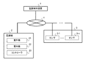
- FIG. It is a block diagram which shows an example of the air-conditioning system including the air-conditioning control device which concerns on Embodiment 1.
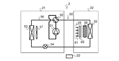
- FIG. It is a refrigerant circuit diagram which shows one configuration example of the air conditioner shown in FIG.
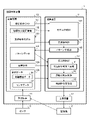
- FIG. It is a block diagram which shows one configuration example of the air-conditioning control device which concerns on Embodiment 1.
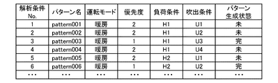
- FIG. It is an image diagram showing an example of the analysis condition list shown in FIG. Among the analysis conditions shown in FIG. 4, it is an image diagram showing an example of the blowing condition regarding the operating state of the air conditioner.
- It is an image diagram when the priority is managed by the numerical range.
- It is an image diagram showing an example of the pattern data shown in FIG.
- FIG. It is a hardware configuration diagram which shows one configuration example of the arithmetic unit shown in FIG. It is a hardware configuration diagram which shows another configuration example of the arithmetic unit shown in FIG. It is a flow diagram which shows an example of the operation procedure of the air-conditioning control device which concerns on Embodiment 1.
- FIG. It is a flow chart which shows an example of the operation procedure in step ST11 shown in FIG. It is a flow chart which shows an example of the operation procedure in step ST15 shown in FIG.
- FIG. 1 is a configuration diagram showing an example of an air conditioning system including the air conditioning control device according to the first embodiment.
- the air conditioning system includes an air conditioner 2 that harmonizes the air in the air conditioning target space, an air conditioning control device 1 that controls the air conditioning device 2, and a sensor 3 that measures at least the environment of the air conditioning target space.
- the air conditioning control device 1 is connected to the air conditioner 2 and the sensor 3 via the network 4.
- FIG. 2 is a refrigerant circuit diagram showing an example of the configuration of the air conditioner shown in FIG.
- the air conditioner 2 has an outdoor unit 21, an indoor unit 22, and a controller 23.
- the indoor unit 22 is installed in a room which is an air-conditioned space.
- the outdoor unit 21 is connected to the indoor unit 22 via a refrigerant pipe 56.
- the outdoor unit 21 has a compressor 51, a four-way valve 52, a heat source side heat exchanger 53, a throttle device 54, and an outdoor fan 57.
- the indoor unit 22 has a load side heat exchanger 55, an indoor fan 58, and a wind direction adjusting unit 59.
- the compressor 51, the heat source side heat exchanger 53, the throttle device 54, and the load side heat exchanger 55 are connected by a refrigerant pipe 56 to form a refrigerant circuit 50 in which the refrigerant circulates.
- a heat medium heat exchanger in which water and the refrigerant exchange heat (not shown). May be provided in the outdoor unit 21 so that water circulates between the outdoor unit 21 and the indoor unit 22.
- the wind direction adjusting unit 59 is provided at the air outlet of the indoor unit 22.
- the wind direction adjusting unit 59 has left and right flaps 61 and upper and lower flaps 62.
- the left and right flaps 61 change the angle clockwise or counterclockwise with respect to the front direction of the air outlet of the indoor unit 22 so that the direction of the airflow sent from the indoor unit 22 is parallel to the floor surface. Change.
- the direction of the airflow that changes according to the angle of the left and right flaps 61 is the left and right wind direction.
- the clockwise angle is represented by a positive value
- the counterclockwise angle is represented by a negative value with respect to the front direction of the air outlet of the indoor unit 22.
- the upper and lower flaps 62 change the direction of the airflow sent from the indoor unit 22 by changing the angle from the gravity direction to the horizontal direction with respect to the gravity direction at the outlet of the indoor unit 22.
- the gravity direction is 0 °
- the horizontal direction is 90 °.
- the direction of the airflow that changes according to the angle of the upper and lower flaps 62 is the vertical wind direction.
- the method of displaying the angle indicating the vertical wind direction is not limited to the case where the gravity direction is 0 ° and the horizontal direction is 90 °, and the gravity direction may be 90 ° and the horizontal direction may be 0 °. That is, when the horizontal direction is 0 °, the depression angle corresponds to the angle indicating the vertical wind direction.
- the controller 23 is, for example, a microcomputer.
- the controller 23 is connected to the compressor 51, the four-way valve 52, the outdoor fan 57, the throttle device 54, the indoor fan 58, and the wind direction adjusting unit 59 via a signal line (not shown in the figure).
- the controller 23 is a device for the user or the administrator to switch the indoor unit 22 on and off, and to manually change the set temperature, air volume, and the like.
- the controller 23 may be a remote controller.
- the controller 23 controls the refrigerating cycle of the refrigerant circulating in the refrigerant circuit 50.
- the controller 23 controls the four-way valve 52 so that the flow direction of the refrigerant in the refrigerant circuit 50 is switched according to the operation modes of the heating operation and the cooling operation. Further, the controller 23 has the operating frequency of the compressor 51, the opening degree of the throttle device 54, and the outdoor fan so that the indoor temperature and humidity measured by the sensor 3 match the respective set values within a predetermined range.
- the rotation speed of 57 is controlled.
- the room temperature and humidity settings are set by the user.
- the controller 23 transmits air-conditioning operation data indicating the operating state of the air conditioner 2 to the air-conditioning control device 1 via the network 4 at regular time intervals.
- the fixed time interval is, for example, 5 minutes.
- the controller 23 When the controller 23 receives a control command from the air conditioning control device 1, the controller 23 controls the rotation speed of the indoor fan 58, the angle of the left and right flaps 61 of the wind direction adjusting unit 59, and the angle of the upper and lower flaps 62 according to the control command. ..
- the air volume and speed are adjusted according to the rotation speed of the indoor fan 58.
- the left and right wind directions are adjusted according to the angles of the left and right flaps 61, and the up and down wind directions are adjusted according to the angles of the upper and lower flaps 62.
- the refrigerant absorbs heat in the heat source side heat exchanger 53, and the refrigerant exchanges heat with the indoor air in the load side heat exchanger 55 to dissipate heat, thereby warming the indoor air.
- the refrigerant dissipates heat in the heat source side heat exchanger 53, and the refrigerant exchanges heat with the indoor air in the load side heat exchanger 55 to cool the indoor air.
- the air conditioner 2 may be a room air conditioner in which a plurality of indoor units 22 are connected to one outdoor unit.
- the air conditioner 2 may be a multi air conditioner for buildings used in office buildings and the like.
- the air conditioning system may be a central air conditioning system used for air conditioning in a large building.
- the air conditioning system may be an air conditioning system installed in a server room, a warehouse, or the like to perform objective air conditioning.
- These configurations are examples of an air conditioning system including the air conditioner 2 and the air conditioner 2, and the type of the air conditioner 2 is not limited to the above-mentioned configuration.
- the space subject to air conditioning is not limited to the above-mentioned spaces such as rooms and buildings.
- the sensor 3 is a sensor that measures a physical quantity.
- the sensor 3 transmits the sensor data, which is a measured value, to the air conditioning control device 1 via the network 4 at regular time intervals.
- the fixed time interval is, for example, 5 minutes.
- the number of sensors 3 may be one or a plurality.
- FIG. 1 shows a case where the sensor 3 has a plurality of sensors 3-1 to 3-n (n is an integer of 2 or more).
- the sensor 3 acquires information on the indoor and outdoor environments.
- the sensor 3 is a sensor that measures temperature, humidity, radiation temperature, thermal image, air flow velocity, and the like. When the sensor 3 includes an infrared sensor, the thermal image is acquired by the infrared sensor.
- the sensor 3 may be provided in the air conditioner 2.
- the sensor 3 for measuring the room temperature which is the temperature of the indoor air
- the sensor 3 for measuring the outdoor air temperature which is the temperature of the outdoor air
- the outside air temperature is not limited to the case where the sensor 3 transmits to the air conditioning control device 1.
- a server (not shown) that provides the weather forecast via a network such as the Internet may transmit information on the outside air temperature to the air conditioning control device 1.
- the network 4 is a communication network that connects the air conditioning control device 1 with the air conditioner 2 and the sensor 3.
- the communication means in the network 4 may be wired or wireless, or may be a combination of wired and wireless.
- the communication protocol for communication performed via the network 4 is not particularly limited, and may be a general-purpose protocol that is open to the public.
- the communication range of the network 4 may be a narrow range such as a LAN (Local Area Network) or a wide range such as the Internet.
- the communication protocol used in the network 4 may be a dedicated protocol.
- FIG. 3 is a block diagram showing a configuration example of the air conditioning control device according to the first embodiment.
- the air conditioning control device 1 is an information processing device that controls the air conditioner 2.
- the air conditioning control device 1 includes a storage device 13, an arithmetic unit 14, a receiving device 11, and a transmitting device 12.
- the receiving device 11 acquires air conditioning operation data from the air conditioner 2 at regular time intervals, and stores the acquired data in the storage device 13.
- the receiving device 11 acquires sensor data from the sensor 3 at regular time intervals, and stores the acquired data in the storage device 13.
- the fixed time interval is, for example, 5 minutes.
- the case where the receiving device 11 acquires data from the air conditioner 2 and the sensor 3 at the same time interval will be described, but the time interval for acquiring the data from the air conditioner 2 and the data from the sensor 3 will be obtained.
- the time interval to be acquired may be different.
- the transmission device 12 transmits the determined control command to the air conditioner 2.
- the storage device 13 stores the analysis condition list 131, the device and spatial information 132, the airflow analysis model 133, the pattern data 134, the target condition 135, and the measurement data 136 including the air conditioning operation data 36 and the sensor data 37. do.
- the storage device 13 is, for example, an HDD (Hard Disk Drive).
- the storage device 13 may be a semiconductor memory.
- FIG. 4 is an image diagram showing an example of the analysis condition list shown in FIG.
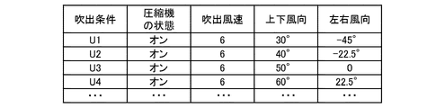
- FIG. 5 is an image diagram showing an example of blowing conditions relating to the operating state of the air conditioner among the analysis conditions shown in FIG.
- FIG. 6 is an image diagram showing an example of a load condition among the analysis conditions shown in FIG.
- the analysis condition list 131 a plurality of analysis conditions consisting of a combination of blowout conditions and load conditions are set.
- the pattern name, the operation mode, the priority, the load condition, the blowout condition, and the pattern generation state are described corresponding to the identifier of the analysis condition.
- the pattern generation state indicates whether or not the airflow analysis is performed according to the analysis conditions and the pattern data is generated based on the result of the airflow analysis. The pattern data will be described in detail later.
- each analysis condition is given a priority.
- the priority is represented by a positive integer. For example, 1 is assigned to the highest priority and 10 is assigned to the lowest priority.
- a unique integer that does not overlap may be attached to each analysis condition, or a unique integer that does not overlap may be attached. For example, there may be a plurality of analysis conditions having a priority of 1, and there may be one analysis condition having a priority of 1.
- the priority assigned to each analysis condition is set based on, for example, the air conditioning operation data 36.
- the higher the frequency of occurrence of the operating states the higher the priority given to the analysis conditions corresponding to the operating states.
- the frequency of occurrence is calculated based on the actual data of the operating state stored in the storage device 13 in a predetermined period such as a fixed period (3 months) in the past. A specific example of the frequency of occurrence will be described. In order to simplify the explanation, it is assumed that the condition that greatly affects the frequency of occurrence of the operating state is the blowout condition, and the frequency of occurrence is obtained as follows, for example.
- the number of occurrences that match the set value is counted for each variable of temperature, air volume, and wind direction at the outlet. Then, among these occurrence times, the occurrence frequency in which each of these three variables matches the set value is defined as the occurrence frequency.
- the frequency of occurrence is calculated for each outlet.
- blowing conditions conditions such as the state of the compressor 51, the blowing wind speed and the blowing wind direction at the blowing outlet of the indoor unit 22 are set.
- the state of the compressor 51 is an on or off state.
- the blowout wind direction is information including the left and right wind direction and the up and down wind direction.
- the blowing conditions may include the blowing air volume and the blowing temperature.
- the number of air outlets provided in the indoor unit 22 may be one or a plurality, and the plurality of indoor units 22 may be installed in a room that is a common air-conditioned space.
- the outlet conditions are composed of a combination of outlet conditions set for each outlet.
- the blowout condition is composed of a combination of blowout conditions set for each outlet of the indoor unit 22.
- the load condition is a condition related to the inflow of heat into the room and the outflow of heat from the room.
- boundary conditions are set as load conditions.
- the boundary condition is a condition relating to the inflow and outflow of heat generated by the temperature difference between the room and the outside from the boundary surface such as a wall surface in the room where the air conditioner 2 is installed.
- the heat passage condition is a condition relating to the inflow and outflow of heat from openings such as windows and doors into the room.
- the heat generation condition is a condition relating to the amount of heat generated indoors due to the human body, OA equipment, and the like.
- FIG. 6 is a table showing conditions relating to heat inflow and outflow into the air-conditioned space as an example of load conditions.
- the load conditions shown in FIG. 6 show some of the boundary conditions, heat transfer conditions, and heat generation conditions.
- the respective values of the wall surface temperature, the ceiling surface temperature, and the floor surface temperature are set corresponding to the load condition identifiers.
- the surface temperature of the wall is represented by the wall temperature Tw
- the surface temperature of the ceiling is represented by the ceiling temperature Tc
- the surface temperature of the floor is represented by the floor temperature Tf.
- the wall temperature Tw 15 ° C.
- the ceiling temperature Tc 25 ° C.
- ⁇ T is, for example, 2 ° C.
- FIG. 7 is an image diagram when the priority is managed by a numerical range.
- the priority is set and managed separately as an essential condition and an additional condition.
- An upper limit priority and a lower limit priority are set for each of the required condition and the additional condition.
- the priority range of the analysis condition that can start the airflow control is set.
- the essential condition indicates that the airflow control can be started when the airflow analysis is performed from the analysis condition with the upper limit priority to the analysis condition with the lower limit priority.
- the priority range of the analysis condition in which the airflow analysis is performed after the start of the airflow control is set.
- the additional condition is that after the airflow control is started, the airflow analysis and the accumulation of the analysis results are called airflow control, from the analysis condition with the upper limit priority to the analysis condition with the lower limit priority. It shows that it can be carried out in parallel.
- an integer 1 is set as the upper limit priority and an integer 3 is set as the lower limit priority as essential conditions.
- the airflow control can be started when the airflow analysis for the analysis conditions with priorities of 1 or more and 3 or less is completed.
- an integer 4 is set in the upper limit priority
- an integer 10 is set in the lower limit priority.
- the airflow analysis and the accumulation of the analysis results can be performed in parallel with the airflow control after the airflow control is started.
- the example shown in FIG. 7 shows a case where the upper limit priority of the essential condition is 1 and the lower limit priority is 3, but the lower limit priority may be 1 which is the same as the upper limit priority.
- the device and spatial information 132 are information necessary for creating the airflow analysis model 133, and are composed of spatial information and device information.
- the spatial information is information about the air-conditioned space in which the air conditioner 2 is installed.
- the spatial information is information including the shape of the room, the arrangement of windows, doors, fixtures, and the like, and the heat insulating performance representing the thermal characteristics of the wall surface, with respect to the room in the air-conditioned space.
- the device information is information regarding the performance of the air conditioner 2.
- the device information is information including the position of the outlet of the air conditioner 2, the capacity and efficiency of the air conditioner 2, and the setable outlet temperature, air volume, and wind direction.
- the information given here is an example, and the device and spatial information 132 are not limited to these information.
- the airflow analysis model 133 is a model used for, for example, a CFD (Computational Fluid Dynamics) analysis method.
- the airflow analysis model 133 is created based on the equipment and spatial information and the analysis conditions in the analysis condition list.
- FIG. 8 is an image diagram showing an example of the pattern data shown in FIG.
- the pattern data is created based on the result of the airflow analysis, and is data showing the tendency of the distribution of the environment such as the temperature and the wind speed in the air-conditioned space.
- the pattern data 134 shown in FIG. 3 means information such as a table in which a plurality of pattern data are recorded. The method of generating the pattern data shown in FIG. 8 will be described later.
- the target condition 135 is a setting condition relating to an environmental target formed by the operation of the air conditioner 2 with respect to the air-conditioned space.
- the target condition 135 is, for example, an upper limit value and a lower limit value of an allowable range to be satisfied by the air-conditioned space for the elements of temperature and wind speed.
- the target condition 135 may be a setting condition for one element or a setting condition for a plurality of elements.
- the target condition 135 may be set for the blowing condition in which a plurality of elements are combined.
- the target condition 135 may have a target value predetermined for each element, or may be set by the user via a remote controller (not shown).
- the target condition 135 is a setting condition for creating an ideal environment that can be derived from the air-conditioned space or an ideal environment that the user considers comfortable.
- the analysis conditions with high priority give priority to airflow analysis in order to perform the airflow control necessary to form the environment of target condition 135 according to the current environment of the air-conditioned space. It is an analysis condition to be performed.
- the air conditioning operation data 36 is, for example, information on set values such as set temperature, air volume, operating states such as left / right wind direction and up / down wind direction, and information used for air conditioning control such as room temperature, outside air temperature, refrigerant temperature, and refrigerant flow rate. ..
- the information used for air conditioning control is measured by a sensor 3 provided in the air conditioner 2.
- the sensor data 37 is data measured by a sensor 3 such as a temperature sensor installed in the room.
- the air conditioning operation data 36 may include the sensor data 37.
- the arithmetic unit 14 includes a model creation unit 141, an airflow analysis unit 142 that performs airflow analysis for each analysis condition, a pattern generation unit 143 that generates pattern data from the analysis results, and an air conditioner 2 based on the pattern data or the analysis results. It has an airflow control unit 144 that controls the airflow of the above.
- the model creation unit 141 creates a model to be used for airflow analysis.
- the model creation unit 141 creates shape data that specifies the room shape, the arrangement of windows and fixtures, and the position of the air outlet of the air conditioner 2 based on the equipment and spatial information, and creates a plurality of analysis target areas. Performs the process of dividing into small spaces.
- the model creation unit 141 is based on the analysis conditions, the conditions regarding the inflow and outflow of heat from the wall surface into the analysis target area, the heat generation conditions due to the heat generation of the human body and the heat generation of the OA device in consideration of the position of the furniture, and the suction.
- the suction conditions of the inflow temperature and the three-dimensional inflow air velocity at the position of the mouth, and the blowout conditions such as the outflow air volume at the outlet are set.
- the airflow analysis unit 142 calculates the airflow analysis model by a CFD analysis method or the like, and obtains the distribution of the temperature and the wind speed in the room which is the air conditioning target space. For example, the airflow analysis unit 142 divides the air-conditioned space into a large number of minute regions, and calculates the temperature and wind speed of each minute region using the airflow analysis model.
- the governing equation of the fluid used for CFD analysis is, for example, as follows.
- u is a three-dimensional velocity vector
- t is time
- p pressure
- ⁇ density
- ⁇ viscosity coefficient
- ⁇ 0 reference density
- g gravitational acceleration
- C p constant pressure specific heat
- T temperature
- k Is the thermal conductivity and Q is the internal calorific value.
- Equation (1) is a continuity equation representing the conservation of mass of a fluid.
- Equation (2) is an incompressible Navier-Stokes equation representing momentum conservation.
- Equation (3) is an energy equation.
- the airflow analysis unit 142 calculates the temperature, wind speed, etc. of each divided region by solving these equations (1) to (3) under appropriate initial values and boundary conditions. In this case, the air conditioning operation data 36 and the sensor data 37 of the air conditioner 2 are used as initial values and boundary condition values in the airflow analysis.
- the analysis conditions included in the airflow analysis model are given priority, and the airflow analysis unit 142 performs airflow analysis according to the order of these priorities. After the airflow analysis of the analysis conditions with predetermined priorities is completed, the airflow control can be started. After that, the airflow control is executed by the airflow control unit 144 at regular time intervals (for example, every 5 minutes), during which the airflow analysis unit 142 temporarily suspends the calculation for the analysis conditions for which the airflow analysis has not been performed. Alternatively, the calculation may be continued by parallel processing.
- the airflow control unit 144 can start airflow control using airflow analysis at an early stage. In this case, it is possible to cause the air conditioner 2 to start the most efficient operation at an early stage among the operating states that have been operated in the past.
- the airflow analysis unit 142 continues to analyze the airflow even after the airflow control is started, and the analysis result is based on the analysis conditions corresponding to the operating state with a low operating record. Is accumulated. After that, the airflow control unit 144 can include an operating state with a low operating record as an option for airflow control.
- the pattern generation unit 143 generates pattern data that expresses the tendency of the distribution of the environment in the air-conditioned space with fewer variables than the airflow analysis result by performing statistical processing on the airflow analysis result.
- the storage device 13 can reduce the amount of data to be stored as compared with the case of storing the generated pattern data in the state of the airflow analysis result.
- FIG. 8 is a diagram showing an example of pattern data. Explaining the case of temperature as an example of variables, the pattern generation unit 143 generates pattern data as follows.
- the pattern generation unit 143 divides the room to be the air-conditioned space into a plurality of small areas, and among the measured values of the temperature of each small area, the measured value of the temperature of the area where the resident may exist. Extract.
- the area where the resident may be present is, for example, an area from the floor surface to a height of 1.1 m above the floor.
- the pattern generation unit 143 sets a plurality of temperature ranges based on the preset upper and lower limit values of the temperature and the number of divisions of the temperature range.
- the pattern generation unit 143 projects a small area included in each temperature range onto a surface parallel to the floor surface, and pattern data showing the temperature distribution so that the total ratio of the areas of the projected surfaces becomes 100%. To generate.
- the first category is 20 ° C or higher and lower than 21 ° C
- the temperature is 21 ° C or higher and lower than 22 ° C.
- the second category, ..., And the tenth category consisting of 29 ° C. or higher and lower than 30 ° C. are set in 10 categories.
- the pattern data shows the proportion (%) of the small areas belonging to each temperature range among the areas where residents may exist. show.
- the pattern data differs depending on the pattern with reference to FIG.
- the occurrence rate of the fifth category is 44.43%, and the occurrence rate of the seventh category is 9.7%.
- the occurrence rate of the fifth category is 5.26%
- the occurrence rate of the seventh category is 40.16%. It can be seen that the room temperature of the pattern having the pattern name of patternn002 is higher than that of the pattern having the pattern name of patternn001.
- the method for generating pattern data described with reference to FIG. 8 is an example, and may be another method.
- the variable is not limited to the case of temperature, and the pattern generation unit 143 can generate pattern data for other elements such as wind speed, humidity and comfort index as well as the case of variable temperature.
- the number of variables is not limited to one, and may be multiple.
- the pattern data is represented by a frequency distribution based on any one or more of the indoor temperature, humidity, wind speed, and comfort index in the analysis result.
- the airflow control unit 144 includes an airflow control availability determination unit 41, an operation state determination unit 42, and a control command conversion unit 43.
- the airflow control availability determination unit 41 determines whether or not the airflow control can be started based on the pattern data generation state by the pattern generation unit 143.
- the pattern data is generated corresponding to the analysis conditions with priorities.
- the airflow control availability determination unit 41 determines that the airflow control can be started when all the pattern data corresponding to the analysis conditions set with high priority have been generated.
- the operation state determination unit 42 determines that the airflow control availability determination unit 41 can start the airflow control
- the operation state determination unit 42 realizes the environment closest to the target condition from the plurality of generated pattern data based on the measurement data 136. Select a pattern and determine the operating condition.
- the control command conversion unit 43 converts the operation state determined by the operation state determination unit 42 into a control command that actually gives a command to the air conditioner 2. Then, the control command conversion unit 43 transmits the control command to the air conditioner 2.
- the airflow control availability determination unit 41 determines whether or not the airflow control can be started, the case where the determination is made based on the generation state of the pattern data will be described, but the airflow analysis unit 142 will be described. The determination may be made based on the generation state of the analysis result by.
- a user may select a high-priority operating state from a plurality of operating states. Further, the operating state having a high priority may be randomly set, for example, the operating state having a high priority may be set in advance at equal intervals with respect to the operable range of the air conditioner 2.
- the selectable range of the operating state of the air conditioner 2 is divided into a plurality of ranges in advance, and in each of the divided ranges, one representative operating state is given a high priority and is represented by other operating states. It is conceivable to give a priority that is relatively lower than the priority of the typical operating condition. In this case, the optimum operating condition can be determined from the typical conditions at an early stage, and the range of operating conditions that can be selected for other conditions can be gradually expanded.
- the selectable range of operating conditions is the vertical wind direction of the air outlet of the indoor unit 22.
- the gravity direction is an angle of 0 °
- the horizontal direction is an angle of 90 °
- the selectable range of the vertical wind direction is the range of an angle of 0 ° to 90 °
- the vertical wind direction can be set in 1 ° units.
- the selectable range of the operating state is divided into three categories. The three categories are the first category of 0 ° or more and less than 30 °, the second category of 30 ° or more and less than 60 °, and the third category of 60 ° or more and 90 ° or less.
- a high priority is assigned to the angle 15 ° as a representative value, and a priority relatively lower than the priority of the representative value is assigned to the other angles.
- a high priority is assigned to 45 ° as a representative value, and a priority relatively lower than the priority of the representative value is assigned to other angles.
- a high priority is assigned to 75 ° as a representative value, and a priority relatively lower than the priority of the representative value is assigned to other angles.
- the airflow analysis unit 142 preferentially executes the airflow analysis under the analysis conditions where the vertical wind direction angles are 15 °, 45 °, and 75 °. After that, the airflow analysis unit 142 executes airflow analysis for analysis conditions having angles other than 15 °, 45 °, and 75 ° in the vertical wind direction. Airflow control can be started when the airflow analysis is completed for a typical operating state in each of the divided ranges, and the most efficient operation can be performed from the typical operating states.
- FIG. 9 is a hardware configuration diagram showing a configuration example of the arithmetic unit shown in FIG.
- the arithmetic unit 14 shown in FIG. 3 is composed of a processing circuit 80 as shown in FIG.
- Each function of the model creation unit 141, the airflow analysis unit 142, the pattern generation unit 143, and the airflow control unit 144 shown in FIG. 3 is realized by the processing circuit 80.
- the processing circuit 80 may be, for example, a single circuit, a composite circuit, a programmed processor, a parallel programmed processor, an ASIC (Application Specific Integrated Circuit), or an FPGA (Field-Programmable Gate). It corresponds to Array) or a combination of these.
- the processing circuit 80 may realize each of the functions of the model creation unit 141, the airflow analysis unit 142, the pattern generation unit 143, and the airflow control unit 144. Further, the functions of the model creation unit 141, the airflow analysis unit 142, the pattern generation unit 143, and the airflow control unit 144 may be realized by one processing circuit 80.
- FIG. 10 is a hardware configuration diagram showing another configuration example of the arithmetic unit shown in FIG.
- the arithmetic unit 14 shown in FIG. 3 is composed of a processor 81 such as a CPU (Central Processing Unit) and a memory 82 as shown in FIG.
- a processor 81 such as a CPU (Central Processing Unit)
- a memory 82 as shown in FIG.
- Each function of the model creation unit 141, the airflow analysis unit 142, the pattern generation unit 143, and the airflow control unit 144 is realized by the processor 81 and the memory 82.
- FIG. 10 shows that the processor 81 and the memory 82 are communicably connected to each other via the bus 83.
- the functions of the model creation unit 141, the airflow analysis unit 142, the pattern generation unit 143, and the airflow control unit 144 are realized by software, firmware, or a combination of software and firmware.
- the software and firmware are described as a program and stored in the memory 82.
- the processor 81 realizes the functions of each part by reading and executing the program stored in the memory 82.
- a non-volatile semiconductor memory such as a ROM (Read Only Memory), a flash memory, an EPROM (Erasable and Programmable ROM), and an EEPROM (Electrically Erasable and Programmable ROM) is used.
- a volatile semiconductor memory of RAM Random Access Memory
- a detachable recording medium such as a magnetic disk, a flexible disk, an optical disk, a CD (Compact Disc), an MD (Mini Disc), and a DVD (Digital Versaille Disc) may be used.
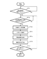
- FIG. 11 is a flow chart showing an example of the operation procedure of the air conditioning control device according to the first embodiment.
- the trigger for starting the flow shown in FIG. 11 is, for example, that the air conditioning control device 1 receives an operation start notification signal indicating that the operation has started from the air conditioner 2.
- the controller 23 of the air conditioner 2 transmits an operation start notification signal to the air conditioning control device 1 when the operation is started.
- step ST11 the airflow control availability determination unit 41 determines whether or not the airflow control can be started. For example, whether or not the pattern data generation is completed by the pattern generation unit 143 based on the result of the airflow analysis under the analysis conditions given by the airflow controlability determination unit 41 with a priority higher than the predetermined priority. Is determined.
- the airflow control availability determination unit 41 determines that the airflow control can be started, and proceeds to step ST12.
- the airflow control possibility determination unit 41 returns to step ST11.
- step ST12 the airflow control unit 144 determines whether or not the timing is the airflow control execution cycle. When the airflow control unit 144 determines that the timing is the airflow control execution cycle, the process proceeds to step ST13. If the airflow control unit 144 determines that the timing is not the airflow control execution cycle, the process returns to step ST12.
- the airflow control execution cycle is a constant cycle such as an interval of 5 minutes.
- the airflow analysis unit 142 continues the airflow analysis for the remaining analysis conditions in order from the analysis condition having the highest priority. Since the airflow analysis is performed in parallel with the airflow control, the result of the airflow analysis under the analysis conditions set to have a relatively low priority is also accumulated in the storage device 13 with the passage of time. The results of airflow analysis under low-priority analysis conditions can also be used at an early stage, and more accurate airflow control can be performed.
- the airflow control unit 144 acquires the air conditioning operation data 36 and the sensor data 37 from the storage device 13.
- the data acquired here is not limited to the current data which is the data acquired from the air conditioner 2 and the sensor 3 at the time closest to the current time.
- the data acquired from the storage device 13 may be past data including the air conditioning operation data 36 and the sensor data 37 stored in the storage device 13 in the past.
- step ST14 the airflow control unit 144 selects a pattern that realizes the state closest to the preset target value from the pattern data generated by the pattern generation unit 143.
- step ST15 the operation state determination unit 42 determines the operation state of the air conditioner 2 with reference to the blowing conditions of the air conditioner 2 corresponding to the pattern selected in step ST14.
- step ST16 the control command conversion unit 43 converts the operating state determined in step ST15 into a control command that actually gives a command to the air conditioner 2, and transmits the control command to the air conditioner 2.
- step ST17 the airflow control unit 144 determines whether or not the end condition is satisfied. If the end condition is satisfied, the airflow control unit 144 ends the process. On the other hand, as a result of the determination in step ST17, if the end condition is not satisfied, the airflow control unit 144 returns to step ST12.
- the end condition is, for example, the stop of the air conditioner 2. In this case, when the user or the administrator inputs an instruction to stop the operation of the air conditioner 2, the controller 23 of the air conditioner 2 stops the operation of the air conditioner 2 and stops the operation of the air conditioner 2.
- the indicated stop notification signal is transmitted to the air conditioning control device 1.
- the end condition is not limited to the case where the air conditioner 2 is stopped, and may be a condition that a preset time has been reached from the start of operation of the air conditioner 2. The preset time is the time during which the operation of the air conditioner 2 becomes stable.
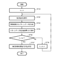
- FIG. 12 is a flow chart showing an example of the operation procedure in step ST11 shown in FIG.
- the priority attached to the analysis condition is an integer k.
- the highest priority among the priorities k ranked in a plurality of ranks is set to 1.
- the lower limit priority of the essential condition shown in FIG. 7 is kL.
- the airflow control availability determination unit 41 determines whether or not the priority k matches the lower limit priority kL (step ST35). As a result of the determination in step ST35, if the priority k does not match the lower limit priority kL, the airflow control possibility determination unit 41 sets a value obtained by adding 1 to the current priority k as the new priority k (step). ST36), return to step ST32.
- step ST35 when the priority k matches the lower limit priority kL, the airflow control availability determination unit 41 determines that the airflow control can be executed (step ST37).
- the airflow control unit 144 executes steps ST32 to ST34 for each of the two or more analysis conditions, and then proceeds to step ST35.
- the air conditioning control can be started at an early stage when the airflow analysis of the analysis conditions including the main blowing conditions is completed.
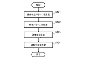
- FIG. 13 is a flow chart showing an example of the operation procedure in step ST15 shown in FIG.
- the pattern selection process by the operation state determination unit 42 will be described with reference to FIG.
- the air conditioner 2 has one indoor unit 22, and the number of air outlets provided in the indoor unit 22 is one.
- the air conditioning operation data 36 includes data of an on / off state of the air conditioner 2, an operation mode indicating a cooling operation or a heating operation, a set temperature, a blowing wind speed, a vertical wind direction, and a left / right wind direction.
- the sensor 3 is an infrared sensor, and the sensor data 37 includes data on the wall surface temperature, the ceiling surface temperature, and the floor surface temperature acquired from the thermal image of the infrared sensor.
- the load conditions are the wall surface temperature, the ceiling surface temperature, and the floor surface temperature
- the blowout conditions are the blowout temperature at one outlet provided in the indoor unit 22, and the vertical and vertical wind directions of the airflow. Left and right wind direction.
- the objects calculated by airflow analysis are temperature and wind speed.
- an upper limit value and a lower limit value are set for each of the wind speed and the temperature on a plane having a predetermined height in the room of the air-conditioned space.
- the operation state determination unit 42 selects the current state pattern, which is a pattern close to the current operation state, as follows.
- the operation state determination unit 42 acquires the on / off state of the air conditioner 2, the operation mode, the blowout wind speed, the vertical wind direction, and the left and right wind direction from the air conditioning operation data 36, and the blowout condition that matches the acquired operation state of the air conditioner 2. Is selected from the blowout conditions in the analysis conditions.
- the operation state determination unit 42 acquires the wall surface temperature, the ceiling surface temperature, and the floor surface temperature from the sensor data 37, and subtracts the floor surface temperature from the acquired ceiling surface temperature to obtain the ceiling surface temperature and the floor. Obtain the upper and lower temperature difference, which is the temperature difference from the surface temperature.
- the operating state determination unit 42 also obtains the vertical temperature difference by subtracting the floor temperature from the ceiling temperature for the load condition in the analysis condition, and obtains the vertical temperature difference and the wall temperature from the sensor data 37, respectively. Compare to determine the closest load condition.
- the pattern data corresponding to the analysis conditions including the determined blowout condition and load condition is uniquely determined.
- the operation state determination unit 42 uses the uniquely determined pattern data as the current state pattern which is the current estimated value of the indoor environment.
- the operation state determination unit 42 extracts a candidate pattern that is a candidate pattern as an estimated value of the indoor environment when the blowout wind speed, the vertical wind direction, and the left / right wind direction are changed from the current state pattern as follows. do.
- the operation state determination unit 42 selects a plurality of blowout conditions in which the on / off state of the air conditioner 2 and the operation mode match, and the blowout wind speed, the vertical wind direction, and the left and right wind directions are different, with reference to the air conditioning operation data 36. ..
- the operation state determination unit 42 includes a plurality of analysis conditions including the same blowout condition as any of the blowout conditions and the same load condition as the load condition determined in step ST21 among the plurality of selected blowout conditions. Is extracted from the analysis condition list.
- the operating state determination unit 42 uses a pattern corresponding to the extracted analysis condition as a candidate pattern. There may be one candidate pattern, but there may be multiple candidate patterns.
- step ST23 the operation state determination unit 42 calculates evaluation values for each of the current state pattern determined in step ST21 and the candidate pattern determined in step ST22.
- the evaluation value For each variable of temperature and wind speed in the pattern data, the ratio of the region included in the preset temperature range is calculated, and the value obtained by multiplying the ratio of each variable by the weighting coefficient is used as the evaluation value.
- the operating state determining unit 42 may determine whether the operating state of the air conditioner 2 is in the transition state or has reached the stable state, and may change the weighting coefficient to be used according to the operating state. ..
- the transient state is a state in which the air conditioner 2 is in a non-stationary process such as immediately after starting.
- the operating state of the air conditioner 2 is determined, for example, by whether or not the elapsed time from the start of activation is equal to or longer than a predetermined threshold time.
- the operation state determination unit 42 determines that the operation state of the air conditioner 2 is a transient state, and the elapsed time from the start of the air conditioner 2 is the threshold time. If it is more than an hour, the operating state of the air conditioner 2 is determined to be a stable state. By changing the weighting coefficient according to the operating condition, the speed of reaching the target value is prioritized immediately after the start of the air conditioner 2, and the comfort is prioritized after the air conditioner 2 stabilizes. It is possible to control the air flow according to the situation.
- the determination of the operating state of the air conditioner 2 is not limited to the above-mentioned determination method.
- the operation state determination unit 42 acquires information on the suction temperature and the set temperature from the air conditioner 2, compares the temperature difference between the suction temperature and the set temperature with a predetermined threshold temperature, and compares the operating state of the air conditioner 2. May be determined. When the temperature difference between the suction temperature and the set temperature is equal to or higher than the threshold temperature, the operation state determination unit 42 determines that the operation state of the air conditioner 2 is a transient state, and the temperature difference between the suction temperature and the set temperature is less than the threshold temperature. If, the operating state of the air conditioner 2 is determined to be a stable state.
- the above-mentioned calculation method of the evaluation value is an example, and may be calculated by another calculation method.
- the evaluation target is not limited to the temperature, but may be a wind speed, or may be an element other than the temperature and the wind speed.
- the evaluation target may be stored in the storage device 13 as a pattern such as a temperature difference between the upper and lower sides at a plurality of positions in the room from the airflow analysis result, and the calculated value may be used as the evaluation value.
- the operation state determination unit 42 may correct the analysis result or the pattern data by using the measured values of one or both of the air conditioning operation data and the sensor data, and use the corrected analysis result or the pattern data.
- a sensor 3 for measuring the suction temperature which is the temperature of the air sucked into the suction port of the air conditioner 2, is provided, and the operation state determination unit 42 acquires the information of the measured value from the sensor 3 provided at the suction port. ..
- the operating state determination unit 42 acquires information on the temperature corresponding to the suction temperature from the analysis result or pattern data, and uses the analysis result or the difference value between the measured value and the temperature acquired from the analysis result or pattern data to obtain the analysis result or. Correct the pattern data. By correcting the analysis result or pattern data, this correction is reflected in the airflow control performed in the actual room, and the temperature in the room is corrected. As a result, the error caused by the difference between the analysis condition and the actual condition is corrected, and the airflow control with high accuracy can be performed.
- the operation state determination unit 42 determines the operation state of the air conditioner 2 as follows. When any of the evaluation values of the plurality of candidate patterns calculated in step ST23 is lower than the evaluation value of the current state pattern, the operation state determination unit 42 does not change the operation state. When there is a candidate pattern whose evaluation value is higher than the evaluation value of the current state pattern, the operation state determination unit 42 sets the operation state of the air conditioner 2 corresponding to the blowing condition corresponding to the candidate pattern as the target of the operation state of the air conditioner 2. Determine the value.
- the operation state determination unit 42 selects the candidate pattern having the highest evaluation value, and the air conditioning corresponding to the blowing condition corresponding to the selected candidate pattern.
- the operating state of the machine 2 is determined to be the target value of the operating state of the air conditioner 2.
- the air conditioning control device 1 accumulates the result of airflow analysis for the airflow analysis model created based on the equipment and spatial information and the analysis condition list as pattern data. Then, when performing airflow control, the air conditioning control device 1 selects a pattern satisfying the target condition from the pattern data based on the measurement data and executes the airflow control.
- Each analysis condition in the analysis condition list is given a priority, and the air conditioning control device 1 performs airflow analysis in descending order of priority, so that the airflow is at an early stage when the airflow analysis of the condition with the highest priority is completed. Control can be started. Further, the air conditioning control device 1 can gradually accumulate various pattern data and improve the accuracy of the airflow control by continuing the airflow analysis under the analysis condition having a low priority after the start of the airflow control.
- the model creation unit 141 performs machine learning using the measurement data 136 stored in the storage device 13, and performs airflow analysis so that the airflow analysis model 133 fits into the air conditioning target space. Model 133 may be updated. This further improves the accuracy of airflow analysis.
- the air conditioning control device 1 of the first embodiment is a storage device 13 that stores a plurality of analysis conditions and airflow analysis results for each analysis condition, each of which has a priority, and an arithmetic unit 14 that controls the air conditioner 2. And have.
- the arithmetic unit 14 has an airflow analysis unit 142, an airflow control availability determination unit 41, and an operation state determination unit 42.
- the airflow analysis unit 142 performs airflow analysis in order from the analysis condition having the highest priority among the plurality of analysis conditions.
- the airflow control availability determination unit 41 determines whether or not the airflow control can be started for the air conditioner 2 based on the generation state of the analysis result by the airflow analysis unit 142.
- the operation state determination unit 42 determines the operation state of the air conditioner 2 based on the analysis result by the airflow analysis unit 142.
- each of the plurality of analysis conditions is given a priority, and the airflow analysis is performed in order from the analysis condition with the highest priority, so that the airflow analysis of the analysis condition with the higher priority can be performed.
- Airflow control can be started at an early stage of completion. Since appropriate airflow control is performed early from the start of the air conditioner 2, a comfortable environment can be provided to the user at an early stage. Since the airflow control suitable for the air-conditioned space is performed more quickly, it is possible to suppress unnecessary change of the operating frequency of the compressor 51 and to save energy.
- the air conditioning control device 1 of the first embodiment does not reduce the number of analysis conditions for a plurality of analysis conditions, but preferentially executes the airflow analysis of the analysis conditions having a high priority. Airflow control is started based on the analysis result. Since the airflow analysis under the analysis conditions with high priority is performed, the accuracy of the airflow analysis is suppressed from being impaired.
- the airflow analysis unit 142 performs the airflow analysis under the analysis conditions with low priority in parallel with the airflow control, so that many analysis results can be obtained with the passage of time. It is stored in the storage device 13. Therefore, the air conditioning control device 1 can perform fine airflow control for the user with high accuracy by using the analysis results of many analysis conditions stored in the storage device 13.
- the storage device 13 does not store and manage the result of the airflow analysis as it is, but stores and manages the pattern data showing the distribution of the environment of the air-conditioned space. Therefore, the data size of the analysis result is compressed, and the storage capacity of the storage device 13 can be reduced. Even when there are many analysis conditions, the required storage capacity can be suppressed. As a result, according to the first embodiment, the calculation load and the storage capacity can be reduced, and the airflow control in consideration of the distribution of the thermal environment of the air-conditioned space can be started at an early stage.
- 1 air conditioning control device 2 air conditioning device, 3, 3-1 to 3-n sensor, 4 network, 11 receiving device, 12 transmitting device, 13 storage device, 14 computing device, 21 outdoor unit, 22 indoor unit, 23 controller, 36 air conditioning operation data, 37 sensor data, 41 air flow control availability judgment unit, 42 operation status determination unit, 43 control command conversion unit, 50 refrigerant circuit, 51 compressor, 52 four-way valve, 53 heat source side heat exchanger, 54 throttle device , 55 load side heat exchanger, 56 refrigerant piping, 57 outdoor fan, 58 indoor fan, 59 wind direction control unit, 61 left and right flaps, 62 upper and lower flaps, 80 processing circuit, 81 processor, 82 memory, 83 bus, 131 analysis condition list , 132 equipment and space information, 133 air-conditioning analysis model, 134 pattern data, 135 target conditions, 136 measurement data, 141 model creation unit, 142 air-conditioning analysis unit, 143 pattern generation unit, 144 air-conditioning control unit.
Landscapes
- Engineering & Computer Science (AREA)
- Signal Processing (AREA)
- Chemical & Material Sciences (AREA)
- Combustion & Propulsion (AREA)
- Mechanical Engineering (AREA)
- General Engineering & Computer Science (AREA)
- Physics & Mathematics (AREA)
- Fuzzy Systems (AREA)
- Mathematical Physics (AREA)
- Fluid Mechanics (AREA)
- Air Conditioning Control Device (AREA)
Abstract
Description
本開示の空調制御装置の実施の形態について、図面を参照しながら説明する。図1は、実施の形態1に係る空調制御装置を含む空調システムの一例を示す構成図である。空調システムは、空調対象空間の空気を調和する空調機2と、空調機2を制御する空調制御装置1と、少なくとも空調対象空間の環境を計測するセンサ3とを有する。空調制御装置1は、ネットワーク4を介して、空調機2及びセンサ3と接続される。



Claims (10)
- それぞれに優先度が付された複数の解析条件及び前記解析条件毎の気流解析の結果を記憶する記憶装置と、
空調機を制御する演算装置と、を有し、
前記演算装置は、
前記複数の解析条件のうち前記優先度の高い解析条件から順に前記気流解析を行う気流解析部と、
前記気流解析部による解析結果の生成状態に基づいて前記空調機に対して気流制御を開始できるか否かを判定する気流制御可否判定部と、
前記気流制御を開始できると前記気流制御可否判定部によって判定されると、前記気流解析部による解析結果に基づいて前記空調機の運転状態を決定する運転状態決定部と、を有する、
空調制御装置。 - 前記気流制御可否判定部は、前記複数の解析条件のうち、予め決められた優先度が付与された解析条件の前記気流解析が完了している場合、前記気流制御を開始できると判定する、
請求項1に記載の空調制御装置。 - 前記記憶装置は、前記空調機の運転状態を示す運転データを記憶し、
前記解析条件に付される優先度について、前記空調機の過去の運転状態のうち、運転状態の発生頻度が高いほど、前記運転状態に対応する解析条件に付される優先度が高く設定される、
請求項1又は2に記載の空調制御装置。 - 前記解析条件に付される優先度について、前記空調機の運転状態が吹出条件である場合、前記吹出条件が複数の範囲に区分され、区分けされた範囲毎の代表的な吹出条件に最も高い優先度が設定される、
請求項1又は2に記載の空調制御装置。 - 前記気流解析部は、前記気流制御可否判定部によって気流制御を開始できると判定された後も前記優先度の順に前記解析条件による気流解析を継続する、
請求項1~4のいずれか1項に記載の空調制御装置。 - 前記記憶装置は、前記空調機の運転状態を示す運転データ、及び少なくとも空調対象空間の環境を計測するセンサの計測値であるセンサデータを記憶し、
前記運転状態決定部は、前記空調機の運転状態として、予め決められた目標条件に最も近い吹出条件を前記解析結果に基づいて決定する際、前記空調機の現在の運転状態及び前記センサデータの一方又は両方を用いて前記解析結果を補正する、
請求項1~5のいずれか1項に記載の空調制御装置。 - 前記運転状態決定部は、前記空調機の運転状態として、予め決められた目標条件に最も近い吹出条件を前記解析結果に基づいて決定する際、前記空調機の運転状態が過渡状態であるか安定状態であるかによって異なる係数を用いて前記吹出条件の評価値を算出し、算出した評価値が最も高い吹出条件を前記空調機の現在の運転状態として決定する、
請求項1~5のいずれか1項に記載の空調制御装置。 - 前記演算装置は、前記気流解析部による解析結果から空調対象空間の環境の分布の傾向を前記解析結果よりも少ない変数で表現するパターンデータを生成するパターン生成部を有し、
前記運転状態決定部は、前記パターン生成部によって生成された前記パターンデータに基づいて前記空調機の運転状態を決定する、
請求項1~7のいずれか1項に記載の空調制御装置。 - 前記パターンデータは、前記解析結果における前記空調対象空間の温度、湿度、風速及び快適性指標のうち、いずれか1つ以上に基づく度数分布で表現される、
請求項8に記載の空調制御装置。 - 前記気流制御可否判定部は、前記パターン生成部による前記パターンデータの生成状態に基づいて気流制御を開始できるか否か判定する、
請求項8又は9に記載の空調制御装置。
Priority Applications (5)
| Application Number | Priority Date | Filing Date | Title |
|---|---|---|---|
| US18/025,646 US20230332793A1 (en) | 2020-10-21 | 2020-10-21 | Air conditioning control device |
| PCT/JP2020/039495 WO2022085100A1 (ja) | 2020-10-21 | 2020-10-21 | 空調制御装置 |
| CN202080105416.3A CN116324292B (zh) | 2020-10-21 | 2020-10-21 | 空调控制装置 |
| JP2021512472A JP7042973B1 (ja) | 2020-10-21 | 2020-10-21 | 空調制御装置 |
| EP20958653.6A EP4235048A4 (en) | 2020-10-21 | 2020-10-21 | AIR CONDITIONING CONTROL DEVICE |
Applications Claiming Priority (1)
| Application Number | Priority Date | Filing Date | Title |
|---|---|---|---|
| PCT/JP2020/039495 WO2022085100A1 (ja) | 2020-10-21 | 2020-10-21 | 空調制御装置 |
Publications (1)
| Publication Number | Publication Date |
|---|---|
| WO2022085100A1 true WO2022085100A1 (ja) | 2022-04-28 |
Family
ID=81214524
Family Applications (1)
| Application Number | Title | Priority Date | Filing Date |
|---|---|---|---|
| PCT/JP2020/039495 Ceased WO2022085100A1 (ja) | 2020-10-21 | 2020-10-21 | 空調制御装置 |
Country Status (5)
| Country | Link |
|---|---|
| US (1) | US20230332793A1 (ja) |
| EP (1) | EP4235048A4 (ja) |
| JP (1) | JP7042973B1 (ja) |
| CN (1) | CN116324292B (ja) |
| WO (1) | WO2022085100A1 (ja) |
Families Citing this family (1)
| Publication number | Priority date | Publication date | Assignee | Title |
|---|---|---|---|---|
| EP4502483A4 (en) * | 2022-03-30 | 2025-05-07 | Mitsubishi Electric Corporation | AIR CONDITIONING CONTROL DEVICE AND AIR CONDITIONING CONTROL METHOD |
Citations (3)
| Publication number | Priority date | Publication date | Assignee | Title |
|---|---|---|---|---|
| JP2012063055A (ja) * | 2010-09-15 | 2012-03-29 | Taisei Corp | 空調環境モニタリングシステム |
| JP2016061447A (ja) * | 2014-09-12 | 2016-04-25 | 株式会社東芝 | 空調制御装置、空調制御方法及びコンピュータプログラム |
| WO2019235109A1 (ja) * | 2018-06-06 | 2019-12-12 | 三菱電機株式会社 | 空調制御装置、空調制御方法、及び空調制御システム |
Family Cites Families (9)
| Publication number | Priority date | Publication date | Assignee | Title |
|---|---|---|---|---|
| JP2004116904A (ja) * | 2002-09-26 | 2004-04-15 | Mitsubishi Heavy Ind Ltd | 風路特性予測装置及び風路特性予測方法 |
| JP3803103B2 (ja) * | 2004-05-21 | 2006-08-02 | シャープ株式会社 | イオン濃度分布の予測方法、解析装置およびイオン濃度分布の予測プログラム |
| JP2010281549A (ja) * | 2009-06-08 | 2010-12-16 | Fujitsu General Ltd | 空気調和システム |
| KR101251873B1 (ko) * | 2012-12-20 | 2013-04-10 | 동국대학교 산학협력단 | 지능형 제어 알고리즘을 이용한 건물 공조 제어 방법 |
| US9784464B2 (en) * | 2013-04-22 | 2017-10-10 | Mitsubishi Electric Corporation | Air-conditioning control system and air-conditioning control method |
| WO2016009506A1 (ja) * | 2014-07-16 | 2016-01-21 | 三菱電機株式会社 | 空調制御装置、空調制御方法、および、プログラム |
| JP6562893B2 (ja) * | 2016-11-17 | 2019-08-21 | 株式会社東芝 | パラメータ推定装置、空調システム評価装置、パラメータ推定方法およびプログラム |
| WO2020008550A1 (ja) * | 2018-07-04 | 2020-01-09 | 三菱電機株式会社 | 省エネ管理装置、省エネ管理システム、省エネ管理方法及びプログラム |
| CN109765797A (zh) * | 2018-12-20 | 2019-05-17 | 广东美的暖通设备有限公司 | 一种空调节能仿真系统 |
-
2020
- 2020-10-21 EP EP20958653.6A patent/EP4235048A4/en not_active Withdrawn
- 2020-10-21 WO PCT/JP2020/039495 patent/WO2022085100A1/ja not_active Ceased
- 2020-10-21 CN CN202080105416.3A patent/CN116324292B/zh active Active
- 2020-10-21 JP JP2021512472A patent/JP7042973B1/ja active Active
- 2020-10-21 US US18/025,646 patent/US20230332793A1/en not_active Abandoned
Patent Citations (3)
| Publication number | Priority date | Publication date | Assignee | Title |
|---|---|---|---|---|
| JP2012063055A (ja) * | 2010-09-15 | 2012-03-29 | Taisei Corp | 空調環境モニタリングシステム |
| JP2016061447A (ja) * | 2014-09-12 | 2016-04-25 | 株式会社東芝 | 空調制御装置、空調制御方法及びコンピュータプログラム |
| WO2019235109A1 (ja) * | 2018-06-06 | 2019-12-12 | 三菱電機株式会社 | 空調制御装置、空調制御方法、及び空調制御システム |
Non-Patent Citations (1)
| Title |
|---|
| See also references of EP4235048A4 * |
Also Published As
| Publication number | Publication date |
|---|---|
| CN116324292A (zh) | 2023-06-23 |
| JPWO2022085100A1 (ja) | 2022-04-28 |
| EP4235048A4 (en) | 2023-12-06 |
| EP4235048A1 (en) | 2023-08-30 |
| CN116324292B (zh) | 2025-07-01 |
| JP7042973B1 (ja) | 2022-03-28 |
| US20230332793A1 (en) | 2023-10-19 |
Similar Documents
| Publication | Publication Date | Title |
|---|---|---|
| JP7637861B2 (ja) | 空調制御装置および空調制御方法 | |
| JP5404556B2 (ja) | 空気調和機の制御装置および冷凍装置の制御装置 | |
| JP4980407B2 (ja) | 空気調和機の制御装置、冷凍装置の制御装置 | |
| JP6125104B2 (ja) | 空調制御装置、空調制御方法、および、プログラム | |
| JP5528512B2 (ja) | 制御装置、制御方法及びプログラム | |
| CN110873446B (zh) | 控制空调的方法及装置、存储介质、处理器 | |
| JP7334019B1 (ja) | 空気調和制御装置、空気調和制御方法および空気調和制御プログラム | |
| JP5132757B2 (ja) | 制御装置、制御方法及びプログラム | |
| CN118882189A (zh) | 一种氟泵空调频率控制方法及系统 | |
| Shoukas et al. | Performance assessment of high efficiency variable speed air-source heat pump in cold climate applications | |
| JP7042973B1 (ja) | 空調制御装置 | |
| JP7714060B2 (ja) | 制御装置、空気調和システム、空気調和装置の制御方法及びプログラム | |
| JP7490831B2 (ja) | 空調システムの制御装置、制御方法、制御プログラムおよび空調システム | |
| CN109341014B (zh) | 空调器及其控制方法、装置 | |
| JP2020139705A (ja) | 運転制御方法、運転制御プログラムおよび運転制御装置 | |
| CN109186043A (zh) | 壁挂式空调及其控制方法 | |
| TW202204832A (zh) | 空調系統控制方法 | |
| CN114608147B (zh) | 温度调节设备及其控制方法、控制装置和存储介质 | |
| JP7258172B2 (ja) | 空気調和機の制御装置、空気調和機及び、プログラム | |
| JP5997671B2 (ja) | 空調制御方法および空調制御システム | |
| CN119731602A (zh) | 参数搜索装置和参数搜索方法 | |
| JP7817602B2 (ja) | 空調ゾーニング方法 | |
| CN114992789A (zh) | 空调风口温度的检测方法、空调室内机及空调 | |
| CN119022428B (zh) | 基于大数据的空调净化智能控制方法及系统 | |
| WO2025182089A1 (ja) | 空調制御装置、空調システム、空調制御方法およびプログラム |
Legal Events
| Date | Code | Title | Description |
|---|---|---|---|
| ENP | Entry into the national phase |
Ref document number: 2021512472 Country of ref document: JP Kind code of ref document: A |
|
| 121 | Ep: the epo has been informed by wipo that ep was designated in this application |
Ref document number: 20958653 Country of ref document: EP Kind code of ref document: A1 |
|
| NENP | Non-entry into the national phase |
Ref country code: DE |
|
| ENP | Entry into the national phase |
Ref document number: 2020958653 Country of ref document: EP Effective date: 20230522 |
|
| WWG | Wipo information: grant in national office |
Ref document number: 202080105416.3 Country of ref document: CN |
|
| WWW | Wipo information: withdrawn in national office |
Ref document number: 2020958653 Country of ref document: EP |