WO2022085334A1 - 自律走行システム、自律走行方法、及び自律走行プログラム - Google Patents
自律走行システム、自律走行方法、及び自律走行プログラム Download PDFInfo
- Publication number
- WO2022085334A1 WO2022085334A1 PCT/JP2021/033447 JP2021033447W WO2022085334A1 WO 2022085334 A1 WO2022085334 A1 WO 2022085334A1 JP 2021033447 W JP2021033447 W JP 2021033447W WO 2022085334 A1 WO2022085334 A1 WO 2022085334A1
- Authority
- WO
- WIPO (PCT)
- Prior art keywords
- work
- path
- work area
- traveling
- area
- Prior art date
- Legal status (The legal status is an assumption and is not a legal conclusion. Google has not performed a legal analysis and makes no representation as to the accuracy of the status listed.)
- Ceased
Links
Images






Classifications
-
- G—PHYSICS
- G05—CONTROLLING; REGULATING
- G05D—SYSTEMS FOR CONTROLLING OR REGULATING NON-ELECTRIC VARIABLES
- G05D1/00—Control of position, course, altitude or attitude of land, water, air or space vehicles, e.g. using automatic pilots
- G05D1/02—Control of position or course in two dimensions
- G05D1/021—Control of position or course in two dimensions specially adapted to land vehicles
- G05D1/0212—Control of position or course in two dimensions specially adapted to land vehicles with means for defining a desired trajectory
-
- A—HUMAN NECESSITIES
- A01—AGRICULTURE; FORESTRY; ANIMAL HUSBANDRY; HUNTING; TRAPPING; FISHING
- A01B—SOIL WORKING IN AGRICULTURE OR FORESTRY; PARTS, DETAILS, OR ACCESSORIES OF AGRICULTURAL MACHINES OR IMPLEMENTS, IN GENERAL
- A01B69/00—Steering of agricultural machines or implements; Guiding agricultural machines or implements on a desired track
- A01B69/007—Steering or guiding of agricultural vehicles, e.g. steering of the tractor to keep the plough in the furrow
- A01B69/008—Steering or guiding of agricultural vehicles, e.g. steering of the tractor to keep the plough in the furrow automatic
-
- G—PHYSICS
- G05—CONTROLLING; REGULATING
- G05D—SYSTEMS FOR CONTROLLING OR REGULATING NON-ELECTRIC VARIABLES
- G05D1/00—Control of position, course, altitude or attitude of land, water, air or space vehicles, e.g. using automatic pilots
- G05D1/0088—Control of position, course, altitude or attitude of land, water, air or space vehicles, e.g. using automatic pilots characterized by the autonomous decision making process, e.g. artificial intelligence, predefined behaviours
-
- G—PHYSICS
- G05—CONTROLLING; REGULATING
- G05D—SYSTEMS FOR CONTROLLING OR REGULATING NON-ELECTRIC VARIABLES
- G05D1/00—Control of position, course, altitude or attitude of land, water, air or space vehicles, e.g. using automatic pilots
- G05D1/60—Intended control result
- G05D1/646—Following a predefined trajectory, e.g. a line marked on the floor or a flight path
-
- G—PHYSICS
- G05—CONTROLLING; REGULATING
- G05D—SYSTEMS FOR CONTROLLING OR REGULATING NON-ELECTRIC VARIABLES
- G05D1/00—Control of position, course, altitude or attitude of land, water, air or space vehicles, e.g. using automatic pilots
- G05D1/60—Intended control result
- G05D1/648—Performing a task within a working area or space, e.g. cleaning
- G05D1/6484—Performing a task within a working area or space, e.g. cleaning by taking into account parameters or characteristics of the working area or space, e.g. size or shape
-
- B—PERFORMING OPERATIONS; TRANSPORTING
- B60—VEHICLES IN GENERAL
- B60Y—INDEXING SCHEME RELATING TO ASPECTS CROSS-CUTTING VEHICLE TECHNOLOGY
- B60Y2200/00—Type of vehicle
- B60Y2200/20—Off-Road Vehicles
- B60Y2200/22—Agricultural vehicles
-
- G—PHYSICS
- G05—CONTROLLING; REGULATING
- G05D—SYSTEMS FOR CONTROLLING OR REGULATING NON-ELECTRIC VARIABLES
- G05D2105/00—Specific applications of the controlled vehicles
- G05D2105/15—Specific applications of the controlled vehicles for harvesting, sowing or mowing in agriculture or forestry
-
- G—PHYSICS
- G05—CONTROLLING; REGULATING
- G05D—SYSTEMS FOR CONTROLLING OR REGULATING NON-ELECTRIC VARIABLES
- G05D2107/00—Specific environments of the controlled vehicles
- G05D2107/20—Land use
- G05D2107/21—Farming, e.g. fields, pastures or barns
-
- G—PHYSICS
- G05—CONTROLLING; REGULATING
- G05D—SYSTEMS FOR CONTROLLING OR REGULATING NON-ELECTRIC VARIABLES
- G05D2109/00—Types of controlled vehicles
- G05D2109/10—Land vehicles
Definitions
- the present invention relates to an autonomous driving system for autonomously driving a work vehicle, an autonomous driving method, and an autonomous driving program.
- Patent Document 1 discloses a system in which the inner peripheral work area and the outer peripheral work area are set, respectively, and a traveling path for autonomously traveling a work vehicle in the inner peripheral work area and the outer peripheral work area is generated. There is.
- the shape of the field to be worked is not rectangular but irregular, the following problems may occur.
- the work locus (running locus) of the inner peripheral work area close to the first side of one of the two opposing sides.
- there may be an overlapping region (for example, the overlapping region X10 in FIG. 3) in which the work locus (running locus) of the outer peripheral work region close to the first side partially overlaps.
- An object of the present invention is to provide an autonomous driving system, an autonomous driving method, and an autonomous driving program that generate a traveling route capable of improving work efficiency.
- the autonomous traveling system includes a work area setting processing unit, a work direction setting processing unit, a route setting processing unit, and a route generation processing unit.
- the work area setting processing unit has the shape of the field in a field where the work target of the work vehicle has a shape in which at least one set of opposite sides of a plurality of sides defining the field is not parallel. The corresponding first work area and the second work area outside the first work area are set respectively.
- the work direction setting processing unit sets the work direction of the work vehicle in the first work area.
- the route setting processing unit parallels the first travel path on which the work vehicle first travels from the work start position in the first work area to the work direction among the plurality of sides defining the first work area. Set to a position adjacent to the side.
- the route generation processing unit of the work vehicle in the first work area is based on the work direction set by the work direction setting processing unit and the first traveling route set by the route setting processing unit. Generate a travel route.
- one or a plurality of processors have a shape in which at least one set of opposite sides of a plurality of sides defining the field in the field on which the work vehicle works is not parallel.
- the first work area corresponding to the shape of the field and the second work area outside the first work area are set respectively, and the work direction of the work vehicle in the first work area is set.
- the first travel path on which the work vehicle first travels from the work start position in the first work area is adjacent to the side parallel to the work direction among the plurality of sides defining the first work area. It is a method of executing the setting to the position to be performed and the generation of the traveling path of the working vehicle in the first working area based on the working direction and the first traveling path.
- the autonomous traveling program according to the present invention is a field in which at least one set of opposite sides of a plurality of sides defining the field has a shape in which the opposite sides are not parallel in the field on which the work vehicle works.
- the first work area corresponding to the above and the second work area outside the first work area are set, the work direction of the work vehicle in the first work area is set, and the first work area is set.
- the first travel path on which the work vehicle first travels from the work start position is set at a position adjacent to the side parallel to the work direction among the plurality of sides defining the first work area.
- an autonomous traveling system an autonomous traveling method, and an autonomous traveling program that generate a traveling route capable of improving work efficiency.
- FIG. 1 is a diagram showing a configuration of an autonomous traveling system according to the first embodiment of the present invention.
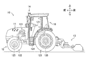
- FIG. 2 is an external view showing an example of a work vehicle according to the first embodiment of the present invention.
- FIG. 3 is a diagram showing an example of a traveling path of a conventional work vehicle.
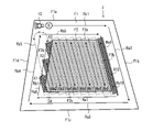
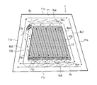
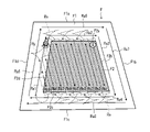
- FIG. 4 is a diagram showing an example of a traveling route of a work vehicle according to the first embodiment of the present invention.
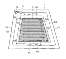
- FIG. 5 is a diagram showing an example of a traveling route of a work vehicle according to the first embodiment of the present invention.
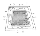
- FIG. 6 is a diagram showing an example of a traveling route of a work vehicle according to the first embodiment of the present invention.
- FIG. 7 is a diagram showing an example of a traveling route of a work vehicle according to the first embodiment of the present invention.
- FIG. 8 is a diagram for explaining a method of setting a travel path of a work vehicle according to the first embodiment of the present invention.
- FIG. 9 is a diagram showing an example of route setting information used for setting a travel route of a work vehicle according to the first embodiment of the present invention.
- FIG. 10 is a flowchart showing an example of a procedure for traveling route generation processing executed by the autonomous traveling system according to the embodiment of the present invention.
- FIG. 11 is a diagram showing an example of a traveling route of the work vehicle according to the second embodiment of the present invention.
- FIG. 12 is a diagram showing an example of a traveling route of a work vehicle according to the second embodiment of the present invention.
- FIG. 13 is a diagram showing an example of a traveling route of the work vehicle according to the second embodiment of the present invention.
- FIG. 14 is a diagram showing an example of a traveling route of a work vehicle according to the second embodiment of the present invention.
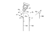
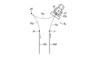
- FIG. 15A is a diagram showing an example of a turning path of a work vehicle according to the second embodiment of the present invention.
- FIG. 15B is a diagram showing an example of a turning path of a work vehicle according to the second embodiment of the present invention.
- FIG. 15C is a diagram showing an example of a turning path of a work vehicle according to the second embodiment of the present invention.
- FIG. 15D is a diagram showing an example of a turning path of a work vehicle according to the second embodiment of the present invention.
- the autonomous traveling system 1 includes a work vehicle 10 and an operation terminal 20.
- the work vehicle 10 and the operation terminal 20 can communicate with each other via the communication network N1.
- the work vehicle 10 and the operation terminal 20 can communicate via a mobile phone line network, a packet line network, or a wireless LAN (Internet, etc.).
- the work vehicle 10 is a tractor
- the work vehicle 10 may be a rice transplanter, a combine harvester, a construction machine, a snowplow, or the like.
- the work vehicle 10 is a so-called robot tractor having a configuration capable of autonomously traveling (automatic traveling) along a traveling path R in a field F (see FIG. 3).
- the work vehicle 10 can autonomously travel along the travel path R generated in advance with respect to the field F based on the position information of the current position of the work vehicle 10 calculated by the positioning device 14. ..
- the work vehicle 10 includes a vehicle control device 11, a traveling device 12, a working machine 13, a positioning device 14, and the like.
- the vehicle control device 11 is electrically connected to a traveling device 12, a working machine 13, a positioning device 14, and the like.
- the vehicle control device 11 and the positioning device 14 may be capable of wireless communication.
- the vehicle control device 11 is a computer system including one or more processors and a storage memory such as a non-volatile memory and a RAM. Then, the vehicle control device 11 controls the operation of the work vehicle 10 in response to various user operations on the work vehicle 10. Further, the vehicle control device 11 executes the autonomous travel process of the work vehicle 10 based on the current position of the work vehicle 10 calculated by the positioning device 14 described later and the travel path R generated in advance.
- the travel path R is stored in the storage memory. Further, the travel path R may be stored in the storage unit 22 of the operation terminal 20.
- the traveling device 12 is a driving unit for traveling the work vehicle 10. As shown in FIG. 2, the traveling device 12 includes an engine 121, front wheels 122, rear wheels 123, a transmission 124, a front axle 125, a rear axle 126, a handle 127, and the like.
- the front wheels 122 and the rear wheels 123 are provided on the left and right sides of the work vehicle 10, respectively. Further, the traveling device 12 is not limited to the wheel type provided with the front wheels 122 and the rear wheels 123, and may be a crawler type provided with crawlers provided on the left and right sides of the work vehicle 10.
- the engine 121 is a drive source such as a diesel engine or a gasoline engine that is driven by using fuel supplied to a fuel tank (not shown).
- the traveling device 12 may include an electric motor as a drive source together with the engine 121 or in place of the engine 121.
- a generator (not shown) is connected to the engine 121, and electric power is supplied from the generator to electric parts such as a vehicle control device 11 provided on the work vehicle 10 and a battery.
- the battery is charged by the electric power supplied from the generator.
- the electric parts such as the vehicle control device 11 and the positioning device 14 provided in the work vehicle 10 can be driven by the electric power supplied from the battery even after the engine 121 is stopped.
- the driving force of the engine 121 is transmitted to the front wheels 122 via the transmission 124 and the front axle 125, and is transmitted to the rear wheels 123 via the transmission 124 and the rear axle 126. Further, the driving force of the engine 121 is also transmitted to the working machine 13 via the PTO shaft (not shown).
- the traveling device 12 performs the traveling operation in accordance with the command of the vehicle control device 11.
- the working machine 13 is, for example, a mowing machine, a tiller, a plow, a fertilizer application machine, a seeding machine, or the like, and can be attached to and detached from the work vehicle 10. As a result, the work vehicle 10 can perform various operations using each of the work machines 13. In the first embodiment, a case where the working machine 13 is a mower will be described as an example.
- the work machine 13 may be supported in the work vehicle 10 so as to be able to move up and down by an elevating mechanism (not shown).
- the vehicle control device 11 can control the elevating mechanism to elevate and lower the working machine 13. For example, the vehicle control device 11 lowers the work machine 13 when the work vehicle 10 moves forward in the work target area of the field F, and raises the work machine 13 when the work vehicle 10 moves backward.
- the steering wheel 127 is an operation unit operated by the user (operator) or the vehicle control device 11.
- the angle of the front wheels 122 is changed by a hydraulic power steering mechanism (not shown) or the like in response to the operation of the steering wheel 127 by the vehicle control device 11, and the traveling direction of the work vehicle 10 is changed.
- the traveling device 12 includes a shift lever (not shown), an accelerator, a brake, and the like operated by the vehicle control device 11. Then, in the traveling device 12, the gear of the transmission 124 is switched to a forward gear, a back gear, or the like according to the operation of the shift lever by the vehicle control device 11, and the traveling mode of the work vehicle 10 is switched to forward or reverse. .. Further, the vehicle control device 11 operates the accelerator to control the rotation speed of the engine 121. Further, the vehicle control device 11 operates the brake and uses an electromagnetic brake to brake the rotation of the front wheels 122 and the rear wheels 123.
- the positioning device 14 is a communication device including a control unit 141, a storage unit 142, a communication unit 143, a positioning antenna 144, and the like.
- the positioning device 14 is provided above the cabin 18 on which the operator is boarded, as shown in FIG. Further, the installation location of the positioning device 14 is not limited to the cabin 18.
- the control unit 141, the storage unit 142, the communication unit 143, and the positioning antenna 144 of the positioning device 14 may be dispersedly arranged at different positions in the work vehicle 10.
- the battery is connected to the positioning device 14, and the positioning device 14 can operate even when the engine 121 is stopped.
- the positioning device 14 for example, a mobile phone terminal, a smartphone, a tablet terminal, or the like may be substituted.
- the control unit 141 is a computer system including one or more processors and a storage memory such as a non-volatile memory and a RAM.
- the storage unit 142 is a program for causing the control unit 141 to execute the positioning process, and a non-volatile memory for storing data such as positioning information and movement information.
- the program is non-temporarily recorded on a computer-readable recording medium such as a CD or DVD, read by a predetermined reading device (not shown), and stored in the storage unit 142.
- the program may be downloaded from the server (not shown) to the positioning device 14 via the communication network N1 and stored in the storage unit 142.
- the communication unit 143 connects the positioning device 14 to the communication network N1 by wire or wirelessly, and executes data communication according to a predetermined communication protocol with an external device such as a base station server via the communication network N1. Communication interface.
- the positioning antenna 144 is an antenna that receives radio waves (GNSS signals) transmitted from satellites.
- GNSS signals radio waves
- the control unit 141 calculates the position (current position) of the work vehicle 10 based on the GNSS signal received from the satellite by the positioning antenna 144. For example, when the work vehicle 10 autonomously travels in the field F and the positioning antenna 144 receives radio waves (transmission time, orbit information, etc.) transmitted from each of the plurality of satellites, the control unit 141 performs positioning. The distance between the antenna 144 and each satellite is calculated, and the current position (latitude and longitude) of the work vehicle 10 is calculated based on the calculated distance.
- control unit 141 calculates the current position of the work vehicle 10 by using the correction information corresponding to the base station (reference station) close to the work vehicle 10, a real-time kinematic method (RTK-GPS positioning method), hereinafter "RTK”. Positioning by the method) may be performed. In this way, the work vehicle 10 autonomously travels by using the positioning information by the RTK method.
- RTK-GPS positioning method real-time kinematic method
- the travel path R on which the work vehicle 10 travels is generated by, for example, the operation terminal 20.
- the work vehicle 10 acquires the data of the travel route R from the operation terminal 20, and performs the work (for example, mowing work) by the work machine 13 while autonomously traveling in the field F according to the travel route R.
- the operation terminal 20 is an information processing device including a control unit 21, a storage unit 22, an operation display unit 23, a communication unit 24, and the like.
- the operation terminal 20 may be composed of a mobile terminal such as a tablet terminal or a smartphone.
- the communication unit 24 connects the operation terminal 20 to the communication network N1 by wire or wirelessly, and data communication according to a predetermined communication protocol with one or more external devices such as a work vehicle 10 via the communication network N1. Is a communication interface for executing.
- the operation display unit 23 is a user interface including a display unit such as a liquid crystal display or an organic EL display that displays various information, and an operation unit such as a touch panel, a mouse, or a keyboard that accepts operations.
- the operator can operate the operation unit to register various information (work vehicle information, field information, work information, etc., which will be described later) on the operation screen displayed on the display unit. .. Further, the operator can operate the operation unit to give an autonomous traveling instruction to the work vehicle 10. Further, the operator can grasp the traveling state of the working vehicle 10 autonomously traveling in the field F according to the traveling route R from the traveling locus displayed on the operation terminal 20 at a place away from the working vehicle 10. ..
- the storage unit 22 is a non-volatile storage unit such as an HDD (Hard Disk Drive) or SSD (Solid State Drive) that stores various types of information.
- the storage unit 22 stores a control program such as a travel route generation program for causing the control unit 21 to execute a travel route generation process (see FIG. 10) described later.
- the travel route generation program is non-temporarily recorded on a computer-readable recording medium such as a CD or DVD, and is read by a reading device (not shown) such as a CD drive or a DVD drive included in the operation terminal 20. It is stored in the storage unit 22.
- the travel route generation program may be downloaded from the server (not shown) to the operation terminal 20 via the communication network N1 and stored in the storage unit 22. Further, the storage unit 22 may store work information (cutting amount, harvesting amount, etc.) transmitted from the work vehicle 10.
- a dedicated application for autonomously traveling the work vehicle 10 is installed in the storage unit 22.
- the control unit 21 activates the dedicated application to set various information about the work vehicle 10, generate a travel route of the work vehicle 10, and give an autonomous travel instruction to the work vehicle 10.
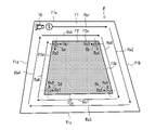
- FIG. 3 shows an example of the field F and an example of the traveling route R corresponding to the field F.
- the field F shown in FIG. 3 has a quadrangular shape divided by an upper side F1a, a right side F1b, a lower side F1c, and a left side F1d. It has a shape that is not.
- the field F includes a first work area (inner peripheral work area F2) in the central portion of the field F and a second work area (outer peripheral work area F1) outside the inner peripheral work area F2.
- the inner peripheral work area F2 has a shape similar to the shape of the field F, and has a rectangular shape divided by an upper side F2a, a right side F2b, a lower side F2c, and a left side F2d, and the opposite upper side F2a and lower side F2c are parallel to each other.
- the right side F2b and the left side F2d facing each other are not parallel to each other.
- the upper side F1a of the field F and the upper side F2a of the inner peripheral work area F2 are parallel
- the right side F1b of the field F and the right side F2b of the inner peripheral work area F2 are parallel
- the lower side F1c of the field F and the inner circumference are parallel.
- the lower side F2c of the work area F2 is parallel, and the left side F1d of the field F and the left side F2d of the inner peripheral work area F2 are parallel.
- the work vehicle 10 works on the outer peripheral work area F1 and then on the inner peripheral work area F2 according to, for example, the traveling path R.
- the traveling path R is a traveling path Ra (traveling paths Ra1 to Ra8) that causes the work vehicle 10 to travel in a spiral shape from the outside to the inside in the outer peripheral work area F1, and the work vehicle 10 on one side in the inner peripheral work area F2. It includes a traveling path Rb (traveling paths Rb1 to Rb10) that reciprocates in parallel from the side to the opposite side.
- traveling paths Ra1 to Ra8 corresponding to the outer peripheral work area F1 are generated.
- the work start position of the inner peripheral work area F2 is the work end position of the outer peripheral work area F1 (travel path Ra8). It is set to the position of the shortest distance (lower left corner Sd in FIG. 3) from the end of).
- a traveling path Ra9 connecting the work start position Sd from the work end position of the outer peripheral work area F1 is generated.
- traveling paths Rb1 to Rb10 parallel to the right side F1b (right side F2b) are generated from the work start position Sd.
- the work vehicle 10 performs work while traveling along the outer peripheral work area F1 according to the traveling paths Ra1 to Ra8, and when the work of the outer peripheral working area F1 is completed, the work vehicle 10 travels (idle) on the traveling path Ra9 and works on the inner peripheral work area F2. Enter the start position Sd. Then, the work vehicle 10 works while traveling along the travel paths Rb1 to Rb10 in the inner peripheral work area F2. When working on the inner peripheral work area F2, the work vehicle 10 turns (turns) in a fishtail shape by using, for example, a switchback when moving to the adjacent traveling path Rb.
- the work locus (travel locus) when traveling in the outer peripheral work area F1 and the work locus (travel locus) when working in the inner peripheral work area F2 overlap. Overlapping areas will occur. Specifically, as shown in FIG. 3, the overlapping region X1 when traveling on the traveling route Rb1 on the left side F2d side, the overlapping region X2 when traveling on the traveling route Rb2, and the overlapping region X2 when traveling on the traveling route Rb3.
- the overlapping region X3 and the overlapping region X10 when traveling on the traveling path Rb10 on the right side F2b side are generated. As described above, according to the conventional technique, there is a problem that the work efficiency is lowered because the overlapping area of the work by the work vehicle 10 is generated.
- the autonomous traveling system 1 has a configuration capable of improving work efficiency by reducing the overlapping area.
- a specific configuration for improving the work efficiency will be described.
- the control unit 21 of the operation terminal 20 includes a vehicle setting processing unit 211, a field setting processing unit 212, a work setting processing unit 213, a work direction setting processing unit 214, a work start position setting processing unit 215, and a route. It includes various processing units such as a setting processing unit 216, a turning setting processing unit 217, a route generation processing unit 218, a display processing unit 219, and an output processing unit 220.
- the control unit 21 functions as the various processing units by executing various processing according to the traveling route generation program on the CPU. Further, a part or all of the processing unit may be composed of an electronic circuit.
- the travel route generation program may be a program for causing a plurality of processors to function as the processing unit.
- the vehicle setting processing unit 211 sets information related to the work vehicle 10 (tractor) (hereinafter referred to as work vehicle information).
- the vehicle setting processing unit 211 refers to the model of the work vehicle 10, the position where the positioning antenna 144 is attached in the work vehicle 10, the type of the work machine 13, the size and shape of the work machine 13, and the work vehicle 10 of the work machine 13.
- Information such as the position, the working vehicle speed and engine rotation speed of the work vehicle 10, the turning vehicle speed and engine rotation speed of the work vehicle 10 is set by the operator performing an operation registered in the operation terminal 20. ..
- the field setting processing unit 212 sets information regarding the field F and the work area (hereinafter referred to as field information).
- the field setting processing unit 212 performs an operation in which the operator registers information such as the position and shape of the field F, the position and shape of the work area, the running start position S to be autonomously run, and the running end position on the operation terminal 20. Set the relevant information by.
- the field setting processing unit 212 is an example of the work area setting processing unit of the present invention.
- the operator gets on the work vehicle 10 and operates so as to make one round around the outer circumference of the field F, and records the transition of the position information of the positioning antenna 144 at that time. By doing so, it can be acquired automatically. Further, the position and shape of the field F are based on a polygon obtained by the operator operating the operation terminal 20 and designating a plurality of points on the map while the map is displayed on the operation terminal 20. You can also get it.
- the positions and shapes (see FIG. 3) of the outer peripheral work area F1 and the inner peripheral work area F2 in the field F can be set by the operator by operating the operation terminal 20.
- the field setting processing unit 212 sets the field F, the outer peripheral work area F1, and the inner peripheral work area F2 based on the operation of the operator.
- the field setting processing unit 212 is a field F that is a work target of the work vehicle 10, and at least one set of opposite sides of a plurality of sides defining the field F is opposed to each other.
- the inner peripheral work area F2 corresponding to the shape of the field F, which is the central portion of the field F, and the outer outer peripheral work of the inner peripheral work area F2.
- Area F1 and each are set.
- the set field F, the outer peripheral work area F1, and the inner peripheral work area F2 are areas (traveling areas) in which the work vehicle 10 can be driven.
- the work setting processing unit 213 sets information (hereinafter referred to as work information) regarding how the work is concretely performed. As work information, the work setting processing unit 213 skips, which is the presence or absence of cooperative work between the work vehicle 10 (unmanned tractor) and the manned work vehicle 10, and the number of work routes to be skipped when the work vehicle 10 turns on the headland. The number, the width of the headland, the width of the non-cultivated land, etc. can be set.
- the work direction setting processing unit 214 sets the work direction of the work vehicle 10 in the inner peripheral work area F2.
- the work direction means a direction in which the work vehicle 10 is driven while working with the work machine 13 in the work area which is the area excluding the non-work area such as the headland and the non-cultivated land from the field F.
- the work direction setting processing unit 214 sets the work direction of the work vehicle 10 to the right side F1b (right side F2b). Set in the direction parallel to.
- the work direction setting processing unit 214 is an example of the work direction setting processing unit of the present invention.
- the work start position setting processing unit 215 sets the work start position of the work vehicle 10 in the inner peripheral work area F2. Specifically, the work start position setting processing unit 215 sets any corner of the plurality of corners of the inner peripheral work area F2 as the work start position. For example, when the work direction of the work vehicle 10 in the inner peripheral work area F2 is registered by the operator in a direction parallel to the right side F1b, the work start position setting processing unit 215 performs the first travel path Rb1 (work) of the inner peripheral work area F2. A corner portion having a positional relationship in which the start path) and the side defining the inner peripheral work area F2 are adjacent to each other is set as the work start position.
- the travel route Rb1 (work start route) is an example of the first travel route of the present invention.
- the work start position setting processing unit 215 has a corner portion Sb at the upper right end where the travel path Rb1 and the right side F2b defining the inner peripheral work area F2 are adjacent to each other. To the work start position. Further, the work start position setting processing unit 215 has a work start position at the corner sc (see FIG. 8) at the lower right end where the travel path Rb1 and the right side F2b defining the inner peripheral work area F2 are adjacent to each other. May be set to.
- the work start position setting processing unit 215 is a corner portion of the corner portions Sb and Sc, in which the moving distance (idle running distance of the traveling path Ra9) from the work ending position (end of the traveling path Ra8) of the outer peripheral work area F1 is short.
- the part Sb may be set to the work start position. That is, the work start position setting processing unit 215 sets the position that is the shortest distance from the work end position (end of the travel path Ra8) of the outer peripheral work area F1 and the position where the travel path Rb1 can be set as the work start position. do.
- the work start position setting processing unit 215 is an example of the work start position setting processing unit of the present invention.
- the route setting processing unit 216 sets the travel path Rb1 (work start route) on which the work vehicle 10 first travels from the work start position in the inner peripheral work area F2 on the plurality of sides F2a to F2d that define the inner peripheral work area F2. Of these, the position is set adjacent to the side parallel to the working direction. Further, the route setting processing unit 216 sets the traveling route Rb1 (work start route) based on the work start position set by the work start position setting processing unit 215. For example, when the work direction of the work vehicle 10 in the inner peripheral work area F2 is set to be parallel to the right side F1b, the work start position setting processing unit 215 sets the corner portion Sb to the work start position as shown in FIG.
- the route setting processing unit 216 sets the traveling route Rb1 (work start route) at a position adjacent to the side F2b parallel to the right side F1b among the plurality of sides F2a to F2d defining the inner peripheral work area F2.
- the route setting processing unit 216 is an example of the route setting processing unit of the present invention.
- the turning setting processing unit 217 sets the turning path of the work vehicle 10.
- the work vehicle 10 turns when it reciprocates in order on the travel paths Rb1 to Rb9 when working on the inner peripheral work area F2.
- the operator can operate the operation terminal 20 to select the turning path of the work vehicle 10.
- the turning setting processing unit 217 sets the turning path of the work vehicle 10 based on the operation of the operator. For example, the operator can select a switchback type turn in which the work vehicle 10 is turned in a fishtail shape, a U-shaped turn in which the work vehicle 10 is turned in a U shape, and the like. Further, the turning setting processing unit 217 can set and change the turning radius and the turning angle.
- the turning setting processing unit 217 is an example of the turning setting processing unit of the present invention.
- the turning setting processing unit 217 may set the same turning path in all the turning portions, or turning in a predetermined traveling path Rb with different turning methods (turning angle, turning path length, etc.). You may set a route.
- the turning setting processing unit 217 uses the turning method of the turning path of the traveling path Rb8 that intersects the side F2d facing the side F2b parallel to the traveling path Rb1 of the work start path in the inner peripheral work area F2 as another traveling path. It may be different from the setting method of the turning path of Rb.
- the autonomous traveling system 1 that employs such different turning paths will be described in the second embodiment described later.
- the route generation processing unit 218 generates a travel route R, which is a route for autonomously traveling the work vehicle 10, based on the setting information.
- the travel path R includes a travel path Ra traveling from the travel start position S to the outer peripheral work area F1 and a travel path Rb traveling from the work start position to the inner peripheral work area F2 (see FIG. 4).
- the travel route R is, for example, a travel route that causes the work vehicle 10 to travel from the outer peripheral work area F1 to the inner peripheral work area F2.
- the route generation processing unit 218 includes a vehicle setting processing unit 211, a field setting processing unit 212, a work setting processing unit 213, a work direction setting processing unit 214, a work start position setting processing unit 215, a route setting processing unit 216, and a turning setting processing. Based on each of the setting information set in the unit 217, the travel path R of the work vehicle 10 can be generated and stored.
- the route generation processing unit 218 is an example of the route generation processing unit of the present invention.
- the route generation processing unit 218 is based on the travel start position S, the work start position, the travel end position, and the work area (outer peripheral work area F1, inner peripheral work area F2) registered in the field setting. Generate R (see FIG. 4). For example, the route generation processing unit 218 generates travel paths Ra1 to Ra8 in the outer peripheral work area F1 based on the travel start position S. Further, the route generation processing unit 218 generates a travel path Ra9 from the work end position (end of the travel path Ra8) of the outer peripheral work area F1 to the work start position Sb.
- the traveling route Ra 9 shown in FIG. 4 shows a route (idle traveling route) in which the working machine 13 is raised and traveled.
- the route generation processing unit 218 has an inner peripheral work area F2 based on the work direction set by the work direction setting processing unit 214 and the traveling route Rb1 (work start route) set by the route setting processing unit 216. Generates the travel path Rb of the work vehicle 10 in the above. For example, as shown in FIG. 4, the route generation processing unit 218 sets the traveling path Rb1 parallel to and adjacent to the side F2b from the work start position Sb and the traveling paths Rb2 to Rb9 following the traveling path Rb1 for the inner peripheral work area F2. Generate a traveling route Rb including. The end position of the travel path Rb9 is set to the travel end position of the field F.
- the display processing unit 219 causes the operation display unit 23 to display various types of information. Specifically, the display processing unit 219 operates a setting screen for setting the work vehicle 10, the field F, the outer peripheral work area F1, the inner peripheral work area F2, the work content, the travel start position S, the travel end position, and the like. Display on 23. Further, the display processing unit 219 causes the operation display unit 23 to display the travel route R generated by the route generation processing unit 218 (see FIG. 4).
- the output processing unit 220 outputs the information of the travel route R generated by the route generation processing unit 218 to the work vehicle 10. Further, the output processing unit 220 can instruct the work vehicle 10 to start and stop autonomous traveling by transmitting a control signal to the work vehicle 10 via the communication unit 24. This makes it possible to autonomously drive the work vehicle 10.
- the data of the travel path R generated in the operation terminal 20 is transferred to the work vehicle 10, stored in the storage memory of the vehicle control device 11, and the current position of the work vehicle 10 is determined by the positioning antenna 144. It is configured to be able to travel autonomously along the traveling route R while detecting. For example, when the current position of the work vehicle 10 matches the travel start position S and the operator presses the work start button on the operation screen and the instruction of "work start” is given, the work vehicle 10 starts autonomous travel. do.
- the vehicle control device 11 autonomously causes the work vehicle 10 to travel from the travel start position S to the travel end position based on the travel path R acquired from the operation terminal 20.
- the vehicle control device 11 may autonomously travel from the travel end position to the entrance of the field F when the work vehicle 10 finishes the work. In this case, it is desirable that the vehicle control device 11 does not travel on the shortest route from the travel end position to the entrance, but autonomously travels from the travel end position to the entrance via the travel route R. As a result, it is possible to prevent the traveling locus (tire mark) of the work vehicle 10 from remaining in the field F after the work is completed.
- control unit 21 can receive the state (position, traveling speed, etc.) of the work vehicle 10 from the work vehicle 10 and display it on the operation display unit 23.
- the operation terminal 20 may be able to access the website (agricultural support site) of the agricultural support service provided by the server (not shown) via the communication network N1.
- the operation terminal 20 can function as an operation terminal of the server by executing the browser program by the control unit 21.
- the server includes each of the above-mentioned processing units and executes each process.
- the overlapping region is limited to the regions X7, X8, and X9, the overlapping region X10 can be reduced as compared with the traveling path R shown in FIG. .. Therefore, it becomes possible to improve the work efficiency of the work vehicle 10.
- control unit 21 generates the travel path R based on the work direction of the work vehicle 10 registered by the operator.
- control unit 21 may set the work direction based on a predetermined condition and generate a travel path R based on the work direction. A specific configuration when the work direction of the work vehicle 10 in the inner peripheral work area F2 is not registered by the operator will be described below.
- the work start position setting processing unit 215 sets the corner portion selected based on a predetermined condition as the work start position among the plurality of corner portions included in the inner peripheral work area F2. For example, as shown in FIG. 5, the work start position setting processing unit 215 performs the work on the corner Sa closest to the work end position of the outer peripheral work area F1 among the plurality of corners included in the inner peripheral work area F2. Set to the start position.
- the work direction setting processing unit 214 sets the work direction based on the work start position (corner portion Sa) set by the work start position setting processing unit 215. For example, the work direction setting processing unit 214 sets the direction parallel to the side of the inner peripheral work area F2 close to the work start position as the work direction. Here, the work direction setting processing unit 214 sets the direction parallel to the left side F2d to the work direction.
- the route setting processing unit 216 sets the travel route Rb1 (work start route) at a position adjacent to the left side F2d parallel to the work direction (see FIG. 5). That is, the route setting processing unit 216 is a position parallel to the work direction and adjacent to the side closest to the work end position of the outer peripheral work area F1 (here, the left side F2d) among the plurality of sides defining the inner peripheral work area F2.
- the travel route Rb1 (work start route) is set in.
- the route generation processing unit 218 generates travel paths Rb1 to Rb9 of the work vehicle 10 in the inner peripheral work area F2 based on the set work direction and the travel path Rb1 (work start route). According to the traveling route R shown in FIG. 5, since the overlapping region is only the regions X7, X8, and X9, the overlapping region can be reduced as compared with the traveling route R shown in FIG. Therefore, it becomes possible to improve the work efficiency of the work vehicle 10.
- the work direction setting processing unit 214 sets the upper side F2a of the inner peripheral work area F2, which is closer to the work start position.
- the direction parallel to the above may be set to the working direction (see FIG. 6).
- the route setting processing unit 216 sets the travel route Rb1 (work start route) at a position adjacent to the upper side F2a parallel to the work direction (see FIG. 6).
- the route generation processing unit 218 generates travel paths Rb1 to Rb8 of the work vehicle 10 in the inner peripheral work area F2 based on the set work direction and the travel path Rb1 (work start route). According to the traveling route R shown in FIG. 6, since the overlapping region is only the region X8, the overlapping region can be reduced as compared with the traveling route R shown in FIG. Therefore, it becomes possible to improve the work efficiency of the work vehicle 10.
- the work start position setting processing unit 215 may set the lower left corner portion Sd to the work start position among the plurality of corner portions included in the inner peripheral work area F2.
- the work direction setting processing unit 214 may set the direction parallel to the lower side F2c close to the work start position (corner portion Sd) of the sides of the inner peripheral work area F2 as the work direction.
- the route setting processing unit 216 sets the travel route Rb1 (work start route) at a position adjacent to the lower side F2c parallel to the work direction.
- the route generation processing unit 218 generates travel paths Rb1 to Rb8 of the work vehicle 10 in the inner peripheral work area F2 based on the set work direction and the travel path Rb1 (work start route). According to the traveling route R shown in FIG. 7, since the overlapping region is only the region X8, the overlapping region can be reduced as compared with the traveling route R shown in FIG. Therefore, it becomes possible to improve the work efficiency of the work vehicle 10.
- the control unit 21 (route setting processing unit 216) is adjacent to the longer side (here, the lower side F2c) as shown in FIG. It is desirable to set the travel route Rb1 (work start route) in. That is, the route setting processing unit 216 sets the work start route at a position parallel to the work direction and adjacent to the longest side among the plurality of sides defining the inner peripheral work area F2. As a result, the overlapping area can be further reduced, so that the work efficiency of the work vehicle 10 can be further improved.
- the work start position in the inner peripheral work area F2 is not limited. Therefore, for example, as shown in FIG. 8, the work start position may be set to any one of the four corners Sa, Sb, Sc, and Sd of the inner peripheral work area F2.
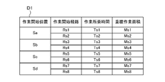
- FIG. 9 shows the route setting information D1 showing the relationship between the work start position, the work start route, the required work time, and the overlapping work area.
- the control unit 21 may generate a travel path Rb in the inner peripheral work area F2 based on the route setting information D1.
- the route setting processing unit 216 works on the field F when it is assumed that the work start route is set at a position adjacent to the side parallel to the side for each side defining the inner peripheral work area F2. The required time is calculated, and the work start route is set at a position adjacent to the side having the shortest work required time among the plurality of sides defining the inner peripheral work area F2. Further, the route setting processing unit 216 works on the inner peripheral work area F2 on the assumption that the work start route is set at a position adjacent to the side parallel to the inner peripheral work area F2 for each side.
- the size of the overlapping area between the locus and the work locus of the outer peripheral work area F1 is calculated, and the work start path is located at a position adjacent to the side where the overlapping area is the smallest among the plurality of sides defining the inner peripheral work area F2. To set.
- control unit 21 calculates the work required time and the overlapping work area when the work start position is set to the corner portion Sa and the work start route is set to the travel path Rs1 (see FIG. 8) by simulation.
- the calculated work required time Ts1 and the overlapping work area Ms1 are registered in the route setting information D1.
- control unit 21 registers the work required time Ts1 and the overlapping work area Ms1 corresponding to each work start position and each work start route in the route setting information D1.
- the work start position setting processing unit 215 sets the optimum work start position with reference to the route setting information D1. For example, the work start position setting processing unit 215 selects and sets the work start position having the shortest work required time among the work start positions (corner portions) registered in the route setting information D1. Further, the work start position setting processing unit 215 may select and set the work start position having the smallest overlapping work area among the work start positions registered in the route setting information D1. The work start position setting processing unit 215 may set the work start position in consideration of both the work required time and the overlapping work area.
- the route setting processing unit 216 sets the optimum work start route with reference to the route setting information D1. Specifically, the route setting processing unit 216 selects and sets the work start route having the shortest work required time among the work start routes registered in the route setting information D1. Further, the route setting processing unit 216 may select and set the work start route having the smallest overlapping work area among the work start routes registered in the route setting information D1. The route setting processing unit 216 may set the work start route in consideration of both the required work time and the overlapping work area.
- the route generation processing unit 218 generates a travel route Rb of the work vehicle 10 in the inner peripheral work area F2 based on the set work start position and the work start route. According to this configuration, the work required time can be shortened and the overlapping area can be reduced. Therefore, it becomes possible to improve the work efficiency of the work vehicle 10.
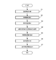
- the travel route generation process is started by the control unit 21 when the control unit 21 receives an instruction from the operator to generate the travel route R of the work vehicle 10.
- the present invention is an invention of a travel route generation method (an example of the autonomous travel method of the present invention) in which a part or all of the travel route generation process is executed by the control unit 21, or a part of the travel route generation method.
- it may be regarded as an invention of a travel route generation program (an example of the autonomous travel program of the present invention) for causing the control unit 21 to execute the entire program.
- the traveling route generation process may be executed by one or a plurality of processors.
- step S1 the control unit 21 acquires various setting information for generating the travel path R. Specifically, the control unit 21 acquires the work vehicle information, the field information, and the work information registered by the operator.
- step S2 the control unit 21 sets a work area. Specifically, the control unit 21 sets the field F, the outer peripheral work area F1, and the inner peripheral work area F2 based on the respective setting information. Further, the control unit 21 sets the travel start position S and the travel end position in step S2. Step S2 is an example of a work area setting step.
- step S3 the control unit 21 sets the work direction of the work vehicle 10 in the inner peripheral work area F2.
- the control unit 21 sets the work direction of the work vehicle 10 to be parallel to the right side F1b.
- the control unit 21 may set the working direction based on the predetermined conditions described above.
- Step S3 is an example of a work direction setting step.
- step S4 the control unit 21 sets the work start position of the work vehicle 10 in the inner peripheral work area F2. Specifically, the control unit 21 sets any corner of the plurality of corners of the inner peripheral work area F2 at the work start position. For example, when the work direction of the work vehicle 10 in the inner peripheral work area F2 is registered by the operator in a direction parallel to the right side F1b, the control unit 21 and the first traveling path Rb1 (work start path) of the inner peripheral work area F2. , The corner portion having a positional relationship adjacent to the side defining the inner peripheral work area F2 is set as the work start position. For example, as shown in FIG. 4, the control unit 21 sets the corner portion Sb at the upper right end portion in which the traveling path Rb1 and the right side F2b defining the inner peripheral work area F2 are adjacent to each other as the work start position. ..
- step S5 the control unit 21 positions the travel path Rb1 (work start path) at a position adjacent to the side parallel to the work direction among the plurality of sides F2a to F2d defining the inner peripheral work area F2.
- the control unit 21 sets the corner portion Sb to the work start position as shown in FIG.
- the traveling route Rb1 (work start route) is set at a position adjacent to the side F2b parallel to the right side F1b among the plurality of sides F2a to F2d that define the peripheral work area F2.
- Step S5 is an example of the routing step of the present invention.
- step S6 the control unit 21 generates a travel route R, which is a route for autonomously traveling the work vehicle 10, based on the setting information.
- the control unit 21 generates travel paths Ra1 to Ra8 in the outer peripheral work area F1 based on the travel start position S, and from the work end position (end of the travel path Ra8) in the outer peripheral work area F1 to the work start position Sb.
- the travel path Ra9 of the above is generated.
- the control unit 21 generates a travel path Rb of the work vehicle 10 in the inner peripheral work area F2 based on the work direction and the work start route (travel path Rb1). For example, as shown in FIG.
- Step S6 is an example of the route generation step of the present invention.
- step S7 the control unit 21 stores the information of the traveling route R in the storage unit 22 and outputs the information to the work vehicle 10.
- the work vehicle 10 autonomously travels the work vehicle 10 based on the information of the travel route R.
- the autonomous traveling system 1 sets the work direction of the work vehicle 10 in the inner peripheral work area F2, and the work start route (first travel route) in which the work vehicle 10 first travels from the work start position in the inner peripheral work area F2.
- the autonomous travel system 1 generates a travel route Rb of the work vehicle 10 in the inner peripheral work region F2 based on the work direction and the work start route.
- the work start route (traveling route Rb1) is set along the side defining the inner peripheral work area F2, so that the occurrence of the overlapping area can be prevented in the side. That is, in the example shown in FIG. 4, since the overlapping region is only the regions X7, X8, and X9 on the side opposite to the side on the work start route side, the overlapping region is compared with the traveling route R shown in FIG. X10 can be reduced. Therefore, it becomes possible to improve the work efficiency of the work vehicle 10.
- the work vehicle 10 includes a work vehicle capable of causing the work machine 13 to perform a predetermined work by mounting the work machine 13 on the work vehicle 10 at an offset to the left or right side with respect to the work vehicle 10 and traveling.
- the tractor working vehicle 10
- the tractor is offset to one of the left and right sides
- a directly mounted work machine 13 is attached to the tractor to run in the field to perform mowing work.
- the work machine 13 is not limited to the directly mounted work machine (see FIG. 2) fixed to the work vehicle 10, and may be a tow type work machine towed by the work vehicle 10. In such a work vehicle 10, the work start position of the inner peripheral work area F2 is limited.
- the work start position setting processing unit 215 sets the corner portion Sd at the lower left end portion or the corner portion Sb at the upper right end portion at the work start position. In this way, the work start position setting processing unit 215 may set the work start position based on the offset direction of the work machine 13.
- the autonomous traveling system according to the present invention may include the configuration of the second embodiment in addition to the configuration of the first embodiment.
- the same configuration as the autonomous traveling system 1 according to the first embodiment will be omitted.
- the work vehicle 10 for performing the mowing work has been described, but in the second embodiment, the work vehicle 10 for performing the tilling work will be described.
- the shapes of the field F, the outer peripheral work area F1, and the inner peripheral work area F2 are the same as those in the first embodiment.
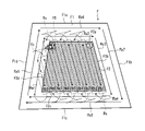
- FIG. 11 shows an example of the traveling route R corresponding to the work vehicle 10 performing the tilling work.
- the field F includes an inner peripheral work area F2 in which the work vehicle 10 reciprocates to perform cultivation work, and an outer peripheral work area F1 in which the work vehicle 10 orbits the outside of the inner peripheral work area F2 to perform cultivation work.
- the work vehicle 10 enters the field F from the entrance, it starts autonomous traveling at the traveling start position S, travels on the traveling routes Rb1 to Rb9, and then travels on the traveling routes Ra1 to Ra8 to perform the work.
- the end of the travel path Ra8 is set at the travel end position.
- the autonomous traveling system 1 has a configuration capable of preventing entry into the cultivated land area and improving work efficiency.
- a specific configuration will be described.
- the turning setting processing unit 217 sets the traveling path Rb intersecting the first side facing the side adjacent to the work start path (traveling path Rb1) among the plurality of sides defining the inner peripheral work area F2.
- a first turning path is set
- a second turning path having a different turning method from the first turning path is set for the traveling path Rb that intersects the other sides other than the first side.
- the turning setting processing unit 217 sets the turning path Ry for the traveling paths Rb7 to Rb9 intersecting the left side F2d facing the right side F2b adjacent to the work start path (traveling path Rb1).
- the turning path Rx is set for the traveling paths Rb1 to Rb6 intersecting the upper side F2a and the lower side F2c excluding the left side F2d.
- the turning path Rx advances the turning path P2a having a turning angle d1 (for example, 90 degrees) to the left from the end p1 of the traveling path Rb2, and moves to the left from the ending p2 of the turning path P2a.
- Go straight on the straight path P2b go backward on the straight path P2c from the end p3 of the straight path P2b, and go forward on the turning path P2d to the left from the end p4 of the straight path P2c toward the start end p5 of the next travel path Rb3. It is a traveling route to be carried out.
- the turning path Ry advances the turning path P2a having a turning angle d2 (however, d2> d1) to the left from the ending p1 of the traveling path Rb8, and the turning path P2a ends p2. From the straight path P2b to the left, go straight on the straight path P2b from the end p3 of the straight path P2b, go backward on the straight path P2c, and turn left from the end p4 of the straight path P2c toward the start end p5 of the next travel path Rb9. It is a traveling route that advances P2d.
- the turning angle d2 of the forward turning included in the turning path Ry is set to an angle larger than the turning angle d1 of the forward turning included in the turning path Rx.
- the turning angle d2 is set to an angle at which the work vehicle 10 does not enter the cultivated land area (for example, the cultivated land area of the traveling path Rb7) when traveling backward on the straight path P2c.
- the turning setting processing unit 217 may set the turning path Ry shown in FIG.
- the turning path Ry shown in FIG. 13 advances the turning path P2a having a turning angle d2 (however, d2> d1) to the left from the end p1 of the traveling path Rb8, and from the end p2 of the turning path P2a.
- Go straight on the straight path P2b to the left go backward on the turning path P2c to the right from the end p3 of the straight path P2b, and turn left from the end p4 of the turning path P2c toward the start end p5 of the next traveling path Rb9. It is a traveling route that advances P2d.
- the turning path Ry includes forward turning (turning paths P2a, P2d) and backward turning (turning path P2c).
- the turning path P2d may be a straight path.
- the turning path Rx includes forward turning (turning paths P2a, P2d) and backward straight-ahead (straight-ahead path P2c), and does not include reverse turning.
- the turning setting processing unit 217 sets the turning path Ry shown in FIG. 12 when the turning angle d2 is less than a predetermined angle, and sets the turning path Ry shown in FIG. 13 when the turning angle d2 is equal to or more than a predetermined angle. You may.
- the turning setting processing unit 217 may set the turning path Ry shown in FIG.
- the turning path Ry shown in FIG. 14 advances the turning path P2a to the right along the left side F2d from the terminal p1 of the traveling path Rb8, and travels straight to the right from the terminal p2 of the turning path P2a. Traveling straight on P2b, traveling backward on the turning path P2c to the left from the end p3 of the straight path P2b, and traveling forward on the turning path P2d to the right from the end p4 of the turning path P2c toward the starting end p5 of the next traveling path Rb9. It is a route. Even with the configuration shown in FIG. 14, it is possible to prevent the entry into the cultivated land area Y8 shown in FIG. 11 and improve the work efficiency.
- the travel path Rb in which the cultivated land area is generated is a travel route in which the end of the travel route Rb is on the side (left side F2d) facing the side (right side F2b) adjacent to the work start route (travel route Rb1). be.
- the travel path Rb where the cultivated land area is generated is the travel path Rb8 among the travel paths Rb7 to Rb9 intersecting the left side F2d. Therefore, in each of the above-described embodiments, the turning setting processing unit 217 may set the turning path Ry for the traveling path Rb8 and set the turning path Rx for the traveling paths Rb7 and Rb9.
- the turning setting processing unit 217 sets the turning path Ry for the traveling path whose end of the traveling path is on the first side side among the plurality of traveling paths intersecting the first side adjacent to the work start path.
- the turning path Rx may be set for the traveling path whose end of the traveling path is not on the first side.
- the autonomous traveling system according to the present invention can be applied to a form in which the above-described first and second embodiments are combined.
- the turning setting processing unit 217 may set any of the turning paths of FIGS. 15B, 15C, and 15D for the traveling path Rb8 included in the traveling path R shown in FIG.
- the traveling route generation process includes a step of setting a turning path, and the control unit 21 sets the turning paths Rx and Ry in the step.
- the autonomous traveling system according to the present invention does not have to have a configuration for reducing the overlapping region shown in the first embodiment. That is, the autonomous traveling system according to the present invention may have only a configuration for preventing entry into the cultivated land area shown in the second embodiment.
- the present invention can be expressed as follows.
- the autonomous driving system is In a field that is a work target of a work vehicle and has a shape in which at least one set of opposite sides of a plurality of sides defining the field is not parallel, a first work area corresponding to the shape of the field and a first work area.
- a work area setting processing unit that sets a second work area outside the first work area, and a work area setting processing unit.
- a work direction setting processing unit that sets the work direction of the work vehicle in the first work area, The first work is based on the turning setting processing unit that sets the turning path of the work vehicle, the working direction set by the working direction setting processing unit, and the turning path set by the turning setting processing unit.
- a route generation processing unit that generates a travel route of the work vehicle in the area, Equipped with The turning setting processing unit faces a side adjacent to a first travel path on which the work vehicle first travels from a work start position in the first work area among a plurality of sides defining the first work area.
- a first turning path is set for a traveling path that intersects one side
- a second turning path that has a different turning method from the first turning path is set for a traveling path that intersects the sides other than the first side. do.
Landscapes
- Engineering & Computer Science (AREA)
- Radar, Positioning & Navigation (AREA)
- Remote Sensing (AREA)
- Aviation & Aerospace Engineering (AREA)
- Physics & Mathematics (AREA)
- General Physics & Mathematics (AREA)
- Automation & Control Theory (AREA)
- Life Sciences & Earth Sciences (AREA)
- Mechanical Engineering (AREA)
- Soil Sciences (AREA)
- Environmental Sciences (AREA)
- Business, Economics & Management (AREA)
- Health & Medical Sciences (AREA)
- Artificial Intelligence (AREA)
- Evolutionary Computation (AREA)
- Game Theory and Decision Science (AREA)
- Medical Informatics (AREA)
- Control Of Position, Course, Altitude, Or Attitude Of Moving Bodies (AREA)
- Guiding Agricultural Machines (AREA)
Abstract
Description
図1に示されるように、本発明の実施形態1に係る自律走行システム1は、作業車両10と操作端末20とを含んでいる。作業車両10及び操作端末20は、通信網N1を介して通信可能である。例えば、作業車両10及び操作端末20は、携帯電話回線網、パケット回線網、又は無線LAN(インターネットなど)を介して通信可能である。
図1及び図2に示されるように、作業車両10は、車両制御装置11、走行装置12、作業機13、及び測位装置14などを備える。車両制御装置11は、走行装置12、作業機13、及び測位装置14などに電気的に接続されている。なお、車両制御装置11及び測位装置14は、無線通信可能であってもよい。
図1に示されるように、操作端末20は、制御部21、記憶部22、操作表示部23、及び通信部24などを備える情報処理装置である。操作端末20は、タブレット端末、スマートフォンなどの携帯端末で構成されてもよい。
以下、図10を参照しつつ、操作端末20の制御部21によって実行される前記走行経路生成処理の一例について説明する。例えば、前記走行経路生成処理は、制御部21がオペレータから作業車両10の走行経路Rを生成する指示を受け付けた場合に制御部21によって開始される。
本発明に係る自律走行システムは、実施形態1の構成に加えて実施形態2の構成を備えてもよい。実施形態2に係る自律走行システム1において、実施形態1に係る自律走行システム1と同一の構成については説明を省略する。なお、実施形態1では、草刈作業を行う作業車両10について説明したが、実施形態2では、耕耘作業を行う作業車両10について説明する。圃場F、外周作業領域F1、及び内周作業領域F2の形状は、実施形態1と同一である。
作業車両の作業対象である圃場であって当該圃場を規定する複数の辺のうち少なくとも一組の対向する辺が平行でない形状を有する圃場において、前記圃場の形状に対応する第1作業領域と、当該第1作業領域の外側の第2作業領域とをそれぞれ設定する作業領域設定処理部と、
前記第1作業領域における前記作業車両の作業方向を設定する作業方向設定処理部と、
前記作業車両の旋回経路を設定する旋回設定処理部と、前記作業方向設定処理部により設定される前記作業方向と前記旋回設定処理部により設定される前記旋回経路とに基づいて、前記第1作業領域における前記作業車両の走行経路を生成する経路生成処理部と、
を備え、
前記旋回設定処理部は、前記第1作業領域を規定する複数の辺のうち前記第1作業領域において作業開始位置から前記作業車両が最初に走行する第1走行経路に隣接する辺に対向する第1辺に交差する走行経路に対して第1旋回経路を設定し、前記第1辺を除く辺に交差する走行経路に対して前記第1旋回経路とは旋回方法が異なる第2旋回経路を設定する。
Claims (15)
- 作業車両の作業対象である圃場であって当該圃場を規定する複数の辺のうち少なくとも一組の対向する辺が平行でない形状を有する圃場において、前記圃場の形状に対応する第1作業領域と、当該第1作業領域の外側の第2作業領域とをそれぞれ設定することと、
前記第1作業領域における前記作業車両の作業方向を設定することと、
前記第1作業領域において作業開始位置から前記作業車両が最初に走行する第1走行経路を、前記第1作業領域を規定する複数の辺のうち前記作業方向に平行な辺に隣接する位置に設定することと、
前記作業方向と前記第1走行経路とに基づいて、前記第1作業領域における前記作業車両の走行経路を生成することと、
を実行する自律走行方法。 - 前記第1作業領域を規定する複数の辺のうち前記作業方向に平行かつ最も長い辺に隣接する位置に前記第1走行経路を設定する、
請求項1に記載の自律走行方法。 - 前記作業車両が前記第2作業領域を作業した後に前記第1作業領域を作業する場合において、
前記第1作業領域を規定する複数の辺のうち前記作業方向に平行かつ前記第2作業領域の作業終了位置に最も近い辺に隣接する位置に前記第1走行経路を設定する、
請求項1に記載の自律走行方法。 - 前記第1作業領域を規定する辺ごとに、当該辺に平行な辺に隣接する位置に前記第1走行経路を設定したと仮定した場合の前記圃場の作業所要時間を算出し、前記第1作業領域を規定する複数の辺のうち前記作業所要時間が最も短くなる辺に隣接する位置に前記第1走行経路を設定する、
請求項1~3のいずれかに記載の自律走行方法。 - 前記第1作業領域を規定する辺ごとに、当該辺に平行な辺に隣接する位置に前記第1走行経路を設定したと仮定した場合の前記第1作業領域の作業軌跡と前記第2作業領域の作業軌跡との重複領域の大きさを算出し、前記第1作業領域を規定する複数の辺のうち前記重複領域が最も小さくなる辺に隣接する位置に前記第1走行経路を設定する、
請求項1~3のいずれかに記載の自律走行方法。 - ユーザーによる前記作業方向を登録する操作に基づいて、前記作業方向を設定する、
請求項1に記載の自律走行方法。 - 前記第1作業領域に含まれる複数の角部のうち、前記第1走行経路と、前記第1作業領域を規定する辺とが隣接する位置関係となる角部を前記作業開始位置に設定する、
請求項6に記載の自律走行方法。 - 前記作業開始位置に基づいて前記第1走行経路に設定する、
請求項7に記載の自律走行方法。 - 前記作業車両は、右方向又は左方向にオフセットして装着される作業機を備え、
前記作業機のオフセット方向に基づいて前記作業開始位置を設定する、
請求項7又は8に記載の自律走行方法。 - 前記作業車両の旋回経路を設定することをさらに実行し、
前記第1作業領域を規定する複数の辺のうち前記第1走行経路に隣接する辺に対向する第1辺に交差する走行経路に対して第1旋回経路を設定し、前記第1辺を除く辺に交差する走行経路に対して前記第1旋回経路とは旋回方法が異なる第2旋回経路を設定する、
請求項1~9のいずれかに記載の自律走行方法。 - 前記第1辺に交差する複数の走行経路のうち走行経路の終端が前記第1辺側となる走行経路に対して前記第1旋回経路を設定し、走行経路の終端が前記第1辺側とならない走行経路に対して前記第2旋回経路を設定する、
請求項10に記載の自律走行方法。 - 前記第1旋回経路は、前進旋回及び後進旋回を含み、
前記第2旋回経路は、前記前進旋回及び後進直進を含み、前記後進旋回を含まない、
請求項10又は11に記載の自律走行方法。 - 前記第1旋回経路に含まれる前記前進旋回の旋回角度は、前記第2旋回経路に含まれる前記前進旋回の旋回角度よりも大きい角度に設定される、
請求項12に記載の自律走行方法。 - 作業車両の作業対象である圃場であって当該圃場を規定する複数の辺のうち少なくとも一組の対向する辺が平行でない形状を有する圃場において、前記圃場の形状に対応する第1作業領域と、当該第1作業領域の外側の第2作業領域とをそれぞれ設定する作業領域設定処理部と、
前記第1作業領域における前記作業車両の作業方向を設定する作業方向設定処理部と、
前記第1作業領域において作業開始位置から前記作業車両が最初に走行する第1走行経路を、前記第1作業領域を規定する複数の辺のうち前記作業方向に平行な辺に隣接する位置に設定する経路設定処理部と、
前記作業方向設定処理部により設定される前記作業方向と前記経路設定処理部により設定される前記第1走行経路とに基づいて、前記第1作業領域における前記作業車両の走行経路を生成する経路生成処理部と、
を備える自律走行システム。 - 作業車両の作業対象である圃場であって当該圃場を規定する複数の辺のうち少なくとも一組の対向する辺が平行でない形状を有する圃場において、前記圃場の形状に対応する第1作業領域と、当該第1作業領域の外側の第2作業領域とをそれぞれ設定することと、
前記第1作業領域における前記作業車両の作業方向を設定することと、
前記第1作業領域において作業開始位置から前記作業車両が最初に走行する第1走行経路を、前記第1作業領域を規定する複数の辺のうち前記作業方向に平行な辺に隣接する位置に設定することと、
前記作業方向と前記第1走行経路とに基づいて、前記第1作業領域における前記作業車両の走行経路を生成することと、
一又は複数のプロセッサーに実行させるための自律走行プログラム。
Priority Applications (4)
| Application Number | Priority Date | Filing Date | Title |
|---|---|---|---|
| US18/031,151 US12429874B2 (en) | 2020-10-21 | 2021-09-13 | Autonomous travel system, autonomous travel method, and autonomous travel program |
| CN202180071820.8A CN116437797A (zh) | 2020-10-21 | 2021-09-13 | 自主行驶系统、自主行驶方法以及自主行驶程序 |
| KR1020237009121A KR20230093243A (ko) | 2020-10-21 | 2021-09-13 | 자율 주행 시스템, 자율 주행 방법, 및 자율 주행 프로그램 |
| EP21882475.3A EP4233503B1 (en) | 2020-10-21 | 2021-09-13 | Autonomous travel system, autonomous travel method, and autonomous travel program |
Applications Claiming Priority (2)
| Application Number | Priority Date | Filing Date | Title |
|---|---|---|---|
| JP2020176637A JP7565749B2 (ja) | 2020-10-21 | 2020-10-21 | 自律走行システム、自律走行方法、及び自律走行プログラム |
| JP2020-176637 | 2020-10-21 |
Publications (1)
| Publication Number | Publication Date |
|---|---|
| WO2022085334A1 true WO2022085334A1 (ja) | 2022-04-28 |
Family
ID=81291194
Family Applications (1)
| Application Number | Title | Priority Date | Filing Date |
|---|---|---|---|
| PCT/JP2021/033447 Ceased WO2022085334A1 (ja) | 2020-10-21 | 2021-09-13 | 自律走行システム、自律走行方法、及び自律走行プログラム |
Country Status (6)
| Country | Link |
|---|---|
| US (1) | US12429874B2 (ja) |
| EP (1) | EP4233503B1 (ja) |
| JP (1) | JP7565749B2 (ja) |
| KR (1) | KR20230093243A (ja) |
| CN (1) | CN116437797A (ja) |
| WO (1) | WO2022085334A1 (ja) |
Families Citing this family (8)
| Publication number | Priority date | Publication date | Assignee | Title |
|---|---|---|---|---|
| JP2022132831A (ja) * | 2021-03-01 | 2022-09-13 | ヤンマーホールディングス株式会社 | 自動運転方法、コンバイン及び自動運転システム |
| JP2023157732A (ja) | 2022-04-15 | 2023-10-26 | キヤノン株式会社 | 通信装置およびその制御方法 |
| AU2022473993A1 (en) * | 2022-08-11 | 2024-11-14 | Deere & Company | Systems and methods for predictive harvesting logistics |
| JP7832884B2 (ja) * | 2022-11-25 | 2026-03-18 | ヤンマーホールディングス株式会社 | 設定方法、自動走行方法、設定システム、及び設定プログラム |
| JP7805915B2 (ja) * | 2022-12-23 | 2026-01-26 | 株式会社クボタ | 農作業支援装置、農作業支援システム、農業機械、走行ライン作成方法 |
| US12353209B2 (en) * | 2023-01-04 | 2025-07-08 | Kubota Corporation | Agricultural support system, and device and method to generate travel route for hailed agricultural machine |
| WO2025110686A1 (ko) * | 2023-11-20 | 2025-05-30 | 엘에스엠트론 주식회사 | 자율주행이 가능한 농업용 작업차량에서의 경로생성방법 및 기록매체 |
| JP2026065336A (ja) | 2024-10-03 | 2026-04-15 | ヤンマーホールディングス株式会社 | 作業車両の制御方法、作業車両用制御プログラム、作業車両用制御システム及び作業システム |
Citations (5)
| Publication number | Priority date | Publication date | Assignee | Title |
|---|---|---|---|---|
| EP1916584A2 (en) * | 2006-10-27 | 2008-04-30 | CNH Belgium N.V. | Nudge compensation for curved swath paths |
| JP2018073050A (ja) * | 2016-10-27 | 2018-05-10 | 株式会社クボタ | 走行経路生成装置 |
| JP2018147421A (ja) | 2017-03-09 | 2018-09-20 | ヤンマー株式会社 | 経路生成システム |
| US20200029487A1 (en) * | 2018-07-30 | 2020-01-30 | Cnh Industrial America Llc | System and method for automatic implement depth measurement control |
| JP2020086877A (ja) * | 2018-11-22 | 2020-06-04 | 井関農機株式会社 | 農作業支援システム |
Family Cites Families (8)
| Publication number | Priority date | Publication date | Assignee | Title |
|---|---|---|---|---|
| JP5881033B2 (ja) * | 2010-12-06 | 2016-03-09 | 国立研究開発法人農業・食品産業技術総合研究機構 | 施肥装置 |
| JP6675135B2 (ja) * | 2016-03-16 | 2020-04-01 | ヤンマー株式会社 | 経路生成装置 |
| JP6531055B2 (ja) * | 2016-03-24 | 2019-06-12 | ヤンマー株式会社 | 経路生成装置 |
| US11726485B2 (en) * | 2016-09-05 | 2023-08-15 | Kubota Corporation | Autonomous work vehicle travel system, travel route managing device, travel route generating device, and travel route determining device |
| WO2018059646A1 (en) * | 2016-09-29 | 2018-04-05 | Agro Intelligence Aps | A system and a method for determining a trajectory to be followed by an agricultural work vehicle |
| WO2018101351A1 (ja) * | 2016-12-02 | 2018-06-07 | 株式会社クボタ | 走行経路管理システム及び走行経路決定装置 |
| JP6811652B2 (ja) | 2017-03-09 | 2021-01-13 | ヤンマーパワーテクノロジー株式会社 | 経路生成システム |
| JP7027142B2 (ja) | 2017-12-06 | 2022-03-01 | ヤンマーパワーテクノロジー株式会社 | 作業車両用の目標経路生成システム |
-
2020
- 2020-10-21 JP JP2020176637A patent/JP7565749B2/ja active Active
-
2021
- 2021-09-13 CN CN202180071820.8A patent/CN116437797A/zh active Pending
- 2021-09-13 US US18/031,151 patent/US12429874B2/en active Active
- 2021-09-13 EP EP21882475.3A patent/EP4233503B1/en active Active
- 2021-09-13 WO PCT/JP2021/033447 patent/WO2022085334A1/ja not_active Ceased
- 2021-09-13 KR KR1020237009121A patent/KR20230093243A/ko active Pending
Patent Citations (5)
| Publication number | Priority date | Publication date | Assignee | Title |
|---|---|---|---|---|
| EP1916584A2 (en) * | 2006-10-27 | 2008-04-30 | CNH Belgium N.V. | Nudge compensation for curved swath paths |
| JP2018073050A (ja) * | 2016-10-27 | 2018-05-10 | 株式会社クボタ | 走行経路生成装置 |
| JP2018147421A (ja) | 2017-03-09 | 2018-09-20 | ヤンマー株式会社 | 経路生成システム |
| US20200029487A1 (en) * | 2018-07-30 | 2020-01-30 | Cnh Industrial America Llc | System and method for automatic implement depth measurement control |
| JP2020086877A (ja) * | 2018-11-22 | 2020-06-04 | 井関農機株式会社 | 農作業支援システム |
Non-Patent Citations (1)
| Title |
|---|
| See also references of EP4233503A4 |
Also Published As
| Publication number | Publication date |
|---|---|
| EP4233503A1 (en) | 2023-08-30 |
| US12429874B2 (en) | 2025-09-30 |
| EP4233503A4 (en) | 2024-08-07 |
| JP2022067820A (ja) | 2022-05-09 |
| US20230376039A1 (en) | 2023-11-23 |
| JP7565749B2 (ja) | 2024-10-11 |
| EP4233503B1 (en) | 2025-09-03 |
| KR20230093243A (ko) | 2023-06-27 |
| CN116437797A (zh) | 2023-07-14 |
Similar Documents
| Publication | Publication Date | Title |
|---|---|---|
| EP4233503B1 (en) | Autonomous travel system, autonomous travel method, and autonomous travel program | |
| JP7720452B2 (ja) | 自律走行システム、自律走行方法、及び自律走行プログラム | |
| JP7704930B2 (ja) | 作業領域設定システム、作業領域設定方法、及び作業領域設定プログラム | |
| US20240096137A1 (en) | Display method, display terminal, and display program | |
| JP7771267B2 (ja) | 自動走行方法及び自動走行システム | |
| JP7641205B2 (ja) | 自動走行方法、自動走行システム、及び自動走行プログラム | |
| CN116610108A (zh) | 路径生成方法、路径生成系统以及路径生成程序 | |
| JP2023079152A (ja) | 経路生成方法、経路生成システム、及び経路生成プログラム | |
| JP7461849B2 (ja) | 自律走行システム、自律走行方法、及び自律走行プログラム | |
| JP7454487B2 (ja) | 走行経路生成システム、走行経路生成方法、及び走行経路生成プログラム | |
| CN116610763A (zh) | 田地登记方法、田地登记系统以及田地登记程序 | |
| KR20250143676A (ko) | 자동 주행 방법, 자동 주행 프로그램, 및 자동 주행 시스템 | |
| KR20250110164A (ko) | 경로 생성 방법, 경로 생성 시스템, 및 경로 생성 프로그램 | |
| JP2023078841A (ja) | 自動走行方法、自動走行システム、及び自動走行プログラム |
Legal Events
| Date | Code | Title | Description |
|---|---|---|---|
| 121 | Ep: the epo has been informed by wipo that ep was designated in this application |
Ref document number: 21882475 Country of ref document: EP Kind code of ref document: A1 |
|
| NENP | Non-entry into the national phase |
Ref country code: DE |
|
| ENP | Entry into the national phase |
Ref document number: 2021882475 Country of ref document: EP Effective date: 20230522 |
|
| WWG | Wipo information: grant in national office |
Ref document number: 2021882475 Country of ref document: EP |
|
| WWG | Wipo information: grant in national office |
Ref document number: 18031151 Country of ref document: US |