WO2022085549A1 - 二重容器 - Google Patents
二重容器 Download PDFInfo
- Publication number
- WO2022085549A1 WO2022085549A1 PCT/JP2021/038004 JP2021038004W WO2022085549A1 WO 2022085549 A1 WO2022085549 A1 WO 2022085549A1 JP 2021038004 W JP2021038004 W JP 2021038004W WO 2022085549 A1 WO2022085549 A1 WO 2022085549A1
- Authority
- WO
- WIPO (PCT)
- Prior art keywords
- container
- peripheral surface
- inner container
- outer container
- double
- Prior art date
- Legal status (The legal status is an assumption and is not a legal conclusion. Google has not performed a legal analysis and makes no representation as to the accuracy of the status listed.)
- Ceased
Links
Images


Classifications
-
- B—PERFORMING OPERATIONS; TRANSPORTING
- B65—CONVEYING; PACKING; STORING; HANDLING THIN OR FILAMENTARY MATERIAL
- B65D—CONTAINERS FOR STORAGE OR TRANSPORT OF ARTICLES OR MATERIALS, e.g. BAGS, BARRELS, BOTTLES, BOXES, CANS, CARTONS, CRATES, DRUMS, JARS, TANKS, HOPPERS, FORWARDING CONTAINERS; ACCESSORIES, CLOSURES, OR FITTINGS THEREFOR; PACKAGING ELEMENTS; PACKAGES
- B65D77/00—Packages formed by enclosing articles or materials in preformed containers, e.g. boxes, cartons, sacks or bags
- B65D77/04—Articles or materials enclosed in two or more containers disposed one within another
- B65D77/048—Articles or materials enclosed in two or more containers disposed one within another the inner and outer containers being rigid and the outer container being of curved cross-section, e.g. cylindrical
- B65D77/0486—Articles or materials enclosed in two or more containers disposed one within another the inner and outer containers being rigid and the outer container being of curved cross-section, e.g. cylindrical the inner container being coaxially disposed within the outer container
- B65D77/0493—Articles or materials enclosed in two or more containers disposed one within another the inner and outer containers being rigid and the outer container being of curved cross-section, e.g. cylindrical the inner container being coaxially disposed within the outer container and retained at a distance of the inner side-wall of the outer container, e.g. within a bottle neck
-
- B—PERFORMING OPERATIONS; TRANSPORTING
- B65—CONVEYING; PACKING; STORING; HANDLING THIN OR FILAMENTARY MATERIAL
- B65D—CONTAINERS FOR STORAGE OR TRANSPORT OF ARTICLES OR MATERIALS, e.g. BAGS, BARRELS, BOTTLES, BOXES, CANS, CARTONS, CRATES, DRUMS, JARS, TANKS, HOPPERS, FORWARDING CONTAINERS; ACCESSORIES, CLOSURES, OR FITTINGS THEREFOR; PACKAGING ELEMENTS; PACKAGES
- B65D77/00—Packages formed by enclosing articles or materials in preformed containers, e.g. boxes, cartons, sacks or bags
- B65D77/04—Articles or materials enclosed in two or more containers disposed one within another
- B65D77/06—Liquids or semi-liquids or other materials or articles enclosed in flexible containers disposed within rigid containers
-
- A—HUMAN NECESSITIES
- A45—HAND OR TRAVELLING ARTICLES
- A45D—HAIRDRESSING OR SHAVING EQUIPMENT; EQUIPMENT FOR COSMETICS OR COSMETIC TREATMENTS, e.g. FOR MANICURING OR PEDICURING
- A45D34/00—Containers or accessories specially adapted for handling liquid toiletry or cosmetic substances, e.g. perfumes
-
- A—HUMAN NECESSITIES
- A45—HAND OR TRAVELLING ARTICLES
- A45D—HAIRDRESSING OR SHAVING EQUIPMENT; EQUIPMENT FOR COSMETICS OR COSMETIC TREATMENTS, e.g. FOR MANICURING OR PEDICURING
- A45D40/00—Casings or accessories specially adapted for storing or handling solid or pasty toiletry or cosmetic substances, e.g. shaving soaps or lipsticks
- A45D40/0068—Jars
-
- A—HUMAN NECESSITIES
- A45—HAND OR TRAVELLING ARTICLES
- A45D—HAIRDRESSING OR SHAVING EQUIPMENT; EQUIPMENT FOR COSMETICS OR COSMETIC TREATMENTS, e.g. FOR MANICURING OR PEDICURING
- A45D2200/00—Details not otherwise provided for in A45D
- A45D2200/05—Details of containers
Definitions
- the present invention relates to a double container, more specifically, a double container including an inner container and an outer container in which the inner container is held and fixed inside.
- Patent Documents 1 and 2 for example, a double container for accommodating contents such as cosmetics and foods is known.
- the double container shown in these patent documents is composed of a bottomed cylindrical inner container that directly stores the contents and a bottomed tubular outer container that holds and fixes the inner container inside. It is a thing.
- Patent Document 1 proposes a structure of a double container in which the inner container can be easily pulled out from the inside of the outer container.
- Patent Document 2 proposes a double container structure in which an inner container (auxiliary container) can be firmly fitted to an outer container (container body).
- the inner container is provided with a rotating pressing portion, and the outer container is provided with a locked portion and a convex portion, so that the structure as a whole is complicated.
- the outer container is formed of an elastically deformable material
- the inner container is formed of a highly rigid hard material to form an outer container. It is considered that the inner container can be relatively easily removed from the outer container because the inner container is elastically deformed so that the inner container can be fitted therein.
- the present invention has been made in view of the above circumstances, and an object of the present invention is to provide a double container which is simple in configuration and whose inner container and outer container can be easily attached and detached.
- One double container An outer container that is a bottomed cylindrical container and has a cross-sectional shape in which the inner peripheral surface of the tubular body is circular and is made of a highly rigid material.
- a bottomed cylindrical container having a cross-sectional shape in which the outer peripheral surface of the tubular body is non-circular, and the radius of the non-circular circumscribed circle is larger than the radius of the inner peripheral surface of the outer container.
- the inner container is elastically deformed and partly fitted to the inner peripheral surface of the outer container. It is characterized by being composed of.
- the above-mentioned "high-rigidity material” means a material that does not elastically or plastically deform to the extent that it can be easily visually recognized under the normal usage state of the double container.
- the inner container is detachable from the outer container by releasing the fitting.
- the inner container is made of polypropylene and the outer container is made of glass.
- Another double container according to the present invention is An inner container that is a bottomed cylindrical container and has a cross-sectional shape with a circular outer peripheral surface of the tubular body and is made of a highly rigid material.
- a bottomed cylindrical container having a cross-sectional shape in which the inner peripheral surface of the tubular body is non-circular, and the radius of the non-circular inscribed circle is larger than the radius of the outer peripheral surface of the inner container.
- One double container according to the present invention An outer container that is a bottomed cylindrical container and has a cross-sectional shape in which the inner peripheral surface of the tubular body is circular and is made of a highly rigid material.
- a bottomed cylindrical container having a cross-sectional shape in which the outer peripheral surface of the tubular body is non-circular, and the radius of the non-circular circumscribed circle is larger than the radius of the inner peripheral surface of the outer container.
- another double container according to the present invention is An inner container that is a bottomed cylindrical container and has a cross-sectional shape with a circular outer peripheral surface of the tubular body and is made of a highly rigid material.
- the inner container and the outer container can be easily attached and detached with a simple structure.
- FIG. (1) to (4) are plan views showing a shape example of an inner container that can be applied in the present invention.
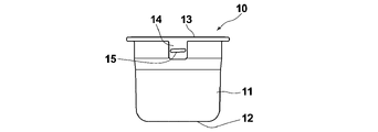
- FIGS. 1 and 2 show the perspective shape and the front shape of the double container 1 according to the embodiment of the present invention, respectively.
- the double container 1 is formed for accommodating a face cream, which is a cosmetic, as an example.
- the double container 1 is configured by holding and fixing the inner container 10 in the outer container 20.
- the inner container 10 shows a perspective shape, a front shape, and a side shape, respectively, in FIGS. 3, 4, and 5, respectively.
- the inner container 10 will be described in detail with reference to FIGS. 3 to 5.
- the inner container 10 is a bottomed tubular member having a cylindrical body portion 11 and a bottom portion 12.
- a flange-shaped flange portion 13 having a circular outer peripheral surface is formed at the upper end of the body portion 11.
- the flange portion 13 is provided with two handle portions 14 extending substantially downward.
- the terms "upper” and “lower” mean the upper and lower parts of the double container 1 in a posture in which the bottom portion 12 is on the lower side.
- the two handle portions 14 are arranged at an angle pitch of 180 ° (degrees) from each other in the circumferential direction of the flange portion 13.
- On the outer surface of each handle portion 14, an elongated boss 15 extending substantially in the lateral direction is formed.
- the boss 15 is provided to prevent the fingers and the like hanging on the handle portion 14 from slipping. Specifically, the boss 15 is formed into a convex shape that serves as a finger hook, or is formed by roughening the surface. To. The detailed shape of the tubular body portion 11 will be described in detail later.
- the inner container 10 having the above shape is integrally formed of PP (polypropylene) as an example. As a result, the body portion 11 can be elastically deformed in the radial direction, that is, in the direction in which the thickness changes. As described above, the inner container 10 contains the face cream as an example.
- the outer container 20 is also a bottomed tubular member having a substantially cylindrical body portion 21 and a bottom portion 22.
- a substantially cylindrical neck portion 23 having a diameter smaller than that of the body portion 21 is integrally formed on the upper portion of the body portion 21.
- a male screw 24 for screwing a cap (not shown) is formed on the outer peripheral surface of the neck portion 23.
- the neck portion 23 is formed with two recesses 25 for fitting the handle portion 14 of the inner container 10 described above. More specifically, when the handle portion 14 is fitted, the recess 25 is provided so that the outer surface of the neck portion 23 other than the recess 25 and the outer surface of the handle portion 14 are substantially flush with each other. It is a portion that is partially thinned by being dug down from the outer surface of the neck portion 23 to the same extent as the thickness.
- the outer container 20 having the above shape is integrally formed of glass, which is an example of a high-rigidity material, as an example.
- the "high-rigidity material” means a material that does not elastically or plastically deform to the extent that it can be easily visually recognized under the normal usage state of the double container.
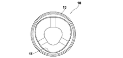
- FIG. 6 schematically shows the cross-sectional shape of the body portion 11
- (2) of the same figure schematically shows the cross-sectional shape of the body portion 21 and the body portion 11 held therein.
- This cross section is a cross section in a plane orthogonal to the cylinder axis direction of the body portions 11 and 21, and if only the body portion 11 is shown, the cross section including the portion shown by the broken line C in FIG. That is.
- the body portion 11 of the inner container 10 has a so-called rice ball-shaped cross-sectional shape in which the apex angle and sides of an equilateral triangle are rounded.
- the body portion 21 of the outer container 20 has a normal cylindrical cross-sectional shape as shown in FIG. 6 (2).
- the diameter D of the circumscribed circle (indicated by the broken line in FIG. 6 (1)) in the cross section of the body portion 11 of the inner container 10 is slightly larger than the maximum inner diameter of the body portion 21 of the outer container 20.
- the diameter D of the circumscribed circle is set to be about 0.2 mm larger than the maximum inner diameter.
- the inner container 10 When combining the inner container 10 and the outer container 20 in which the sizes of the body portions 11 and 21 have the above-mentioned relationship, first, the inner container 10 is arranged in the outer container 20 with the cylinder axis direction parallel to each other.
- the cross-sectional view of FIG. 6 (2) shows the body portions 11 and 21 at this time.
- the portion between the three tops of the body portion 11 of the inner container 10 is elastically deformed as shown by the broken line in the figure.
- the inner container 10 is elastically and firmly fitted in the outer container 20 by expanding the diameter, that is, elastically deforming so as to swell outward in the diameter.
- 1 and 2 show the double container 1 in this state. Since the outer container 20 that can be seen from the outside is made of high-rigidity glass as described above, it does not deform and remains in a beautiful appearance.
- Glass parts generally have a large tolerance, and the outer container 20 does not leak to that example.
- the "maximum inner diameter" described above for the body portion 21 of the outer container 20 is the maximum value that the inner diameter of the body portion 21 can take in consideration of this tolerance.
- the inner container 10 is fitted and integrated with the outer container 20 by utilizing the elastic deformation of the inner container 10 as described above, even if the tolerance of the outer container 20 is relatively large, The inner container 10 and the outer container 20 can be surely fitted and integrated.
- the double container 1 of the present embodiment can be suitably used for using a so-called refill. That is, when the contents such as face cream contained in the inner container 10 are used up, the empty inner container 10 is taken out from the outer container 20 and instead, as a refill filled with the contents. If the new inner container 10 is held and fixed to the outer container 20, the double container 1 can be continuously used without discarding the outer container 20.
- the outer container 20 that can be observed from the outside is usually printed neatly or has a neat sticker affixed to it, and is generally expensive. Therefore, not having to dispose of such an outer container 20 can provide an economic advantage to the user and also has an effect of reducing the burden on the environment.
- the action and effect of the handle portion 14 will be described.
- the inner container 10 does not move in the rotation direction of the cap when the above-mentioned cap is opened for taking out the contents from the inner container 10 or the like. .. If the handle portion 14 is provided so as to be fitted into the recess 25 of the outer container 20 as described above, the inner container 10 is surely prevented from moving in the rotation direction of the cap.
- the handle portion 14 is tightly fitted in the recess 25. Therefore, there is a slight gap between the two, more specifically, between the left and right ends and lower ends of the handle portion 14 and the edge portion of the recess 25, and between the recess 25 of the outer container 20 and the handle portion 14 of the inner container 10. It is desirable to set the size of both so that
- the cross-sectional shape of the body of the inner container is not limited to the shape of the inner container 10 in the above-described embodiment.
- FIG. 7 shows a planar shape when the inner container 10 is viewed from above.
- the shape of the body portion 11 shown here is the same as the cross-sectional shape thereof.
- FIGS. 8 (1) to (4) show four examples of the case where the body portion 11 is similarly viewed from above, that is, four examples of the cross-sectional shape of the body portion 11.
- reference numeral 13 is a flange portion as described above.
- the cross-sectional shape of the body portion 11 may be, for example, a teardrop shape or an oval shape in the inner container 40 of (1), an elliptical shape in the inner container 50 of (2), or (3). It may be a rounded quadrangle in the inner container 60 of the above, or a pentagon with a roundness in the inner container 70 of (4). Further, it may have a cross-sectional shape other than those.
- the double container is a bottomed cylindrical container and has a cross-sectional shape in which the outer peripheral surface of the cylindrical body is circular.
- An inner container made of a highly rigid material and a bottomed cylindrical container having a cross-sectional shape in which the inner peripheral surface of the cylindrical body is non-circular, and the non-circular inscribed circle.
- the radius is smaller than the radius of the outer peripheral surface of the inner container, and when the inner container is arranged parallel to each other in the cylindrical axial direction so as to fit inside, it is elastically deformed and a part of it fits into the outer peripheral surface of the inner container. It can also consist of a matching outer container.
Landscapes
- Engineering & Computer Science (AREA)
- Mechanical Engineering (AREA)
- Packages (AREA)
- Details Of Rigid Or Semi-Rigid Containers (AREA)
- Rigid Containers With Two Or More Constituent Elements (AREA)
Abstract
【課題】有底筒状の内容器を、同じく有底筒状の外容器内に収めてなる二重容器において、内容器と外容器とを容易に着脱可能とする。 【解決手段】筒状の胴部の内周面が円形である横断面形状を有し、高剛性材料から形成された外容器(20)と、筒状の胴部の外周面が非円形である横断面形状を有し、非円形の外接円の半径が前記外容器(20)の内周面の半径より大とされ、外容器(20)内に筒軸方向を互いに平行にして配されたとき、該外容器(20)の内周面に弾性変形して嵌合する内容器(10)とから二重容器(1)を構成する。
Description
本発明は二重容器、より詳しくは、内容器と該内容器を内部に保持、固定した外容器とからなる二重容器に関するものである。
従来、例えば特許文献1や2に示されているように、化粧料や食品等の内容物を収容する二重容器が知られている。これらの特許文献に示された二重容器は、内容物を直接収容する有底筒状の内容器と、この内容器を内部に保持、固定した同じく有底筒状の外容器とから構成されたものである。特に特許文献1には、内容器を外容器内から容易に引き抜き可能にした二重容器の構造が提案されている。一方特許文献2には、外容器(容器本体)に対して内容器(補助容器)を強固に嵌合可能にした二重容器の構造が提案されている。
ところで、上述のような二重容器に対しては、内容器が収容していた化粧料等の内容物が使い切られたなら、その内容器を、内容物を収容している新たなものと交換するようにして、外容器は継続使用したいという要求も存在する。そのような要求に応える上では、特許文献1に示された二重容器、つまり内容器を外容器内から容易に引き抜き可能にした二重容器は特に好ましいものであると言える。
しかし特許文献1に示された二重容器には、内容器には回動する押圧部が設けられ、また外容器には被係止部や凸部が設けられて、全体として構造が複雑であるという問題が認められる。他方、特許文献2に示された二重容器は、外容器(容器本体)を弾性変形可能な材料から形成すると共に、内容器(補助容器)は高剛性の硬質材料から形成して、外容器を弾性変形させてそこに内容器を嵌合可能としたものであるので、外容器からの内容器の取り外しは比較的容易に行い得るものと考えられる。しかし、この特許文献2に示された二重容器は、外容器を上述のように弾性変形させるために、外容器を上から下に向けて次第に縮径するテーパ状にしておく必要がある。さらにこの二重容器では、内容器を上から下に押し込んだとき内容器は外容器の内周面に全周に亘って接するように拡径しながら嵌合することから、放置しておくと内容器が上へ飛び出し得るので、それを防ぐために外容器の開口縁鍔部に嵌合機構が備わっていることが必須となる。以上の事情により、特許文献2に示された二重容器には、外容器を特別な形状に限定する必要があるという問題が認められる。
本発明は上記の事情に鑑みてなされたものであり、構成が簡単で、内容器と外容器とが容易に着脱可能な二重容器を提供することを目的とする。
本発明による一つの二重容器は、
有底筒状の容器であって、筒状の胴部の内周面が円形である横断面形状を有し、高剛性材料から形成された外容器と、
有底筒状の容器であって、筒状の胴部の外周面が非円形である横断面形状を有し、前記非円形の外接円の半径が前記外容器の内周面の半径より大とされ、前記外容器内に筒軸方向を互いに平行にして配されたとき、弾性変形して一部が該外容器の内周面に嵌合する内容器と、
からなることを特徴とするものである。
なお、上記の「高剛性材料」とは、通常の二重容器の使用状態下では、容易に視認可能程度に弾性変形あるいは塑性変形することのない材料を意味するものである。
有底筒状の容器であって、筒状の胴部の内周面が円形である横断面形状を有し、高剛性材料から形成された外容器と、
有底筒状の容器であって、筒状の胴部の外周面が非円形である横断面形状を有し、前記非円形の外接円の半径が前記外容器の内周面の半径より大とされ、前記外容器内に筒軸方向を互いに平行にして配されたとき、弾性変形して一部が該外容器の内周面に嵌合する内容器と、
からなることを特徴とするものである。
なお、上記の「高剛性材料」とは、通常の二重容器の使用状態下では、容易に視認可能程度に弾性変形あるいは塑性変形することのない材料を意味するものである。
なお、上記構成を有する本発明の二重容器においては、内容器が、上記嵌合を解除して外容器から離脱可能とされていることが望ましい。
また、上記構成を有する本発明の二重容器においては、内容器がポリプロピレンからなるものであり、外容器がガラスからなるものであることが望ましい。
また、本発明による別の二重容器は、
有底筒状の容器であって、筒状の胴部の外周面が円形である横断面形状を有し、高剛性材料から形成された内容器と、
有底筒状の容器であって、筒状の胴部の内周面が非円形である横断面形状を有し、前記非円形の内接円の半径が前記内容器の外周面の半径より小とされ、前記内容器を内部に収めるように筒軸方向を互いに平行にして配されたとき、弾性変形して一部が該内容器の外周面に嵌合する外容器と、
からなることを特徴とするものである。
有底筒状の容器であって、筒状の胴部の外周面が円形である横断面形状を有し、高剛性材料から形成された内容器と、
有底筒状の容器であって、筒状の胴部の内周面が非円形である横断面形状を有し、前記非円形の内接円の半径が前記内容器の外周面の半径より小とされ、前記内容器を内部に収めるように筒軸方向を互いに平行にして配されたとき、弾性変形して一部が該内容器の外周面に嵌合する外容器と、
からなることを特徴とするものである。
また、上記構成を有する本発明の別の二重容器においても、内容器が、上記嵌合を解除して外容器から離脱可能とされていることが望ましい。
本発明による一つの二重容器は、
有底筒状の容器であって、筒状の胴部の内周面が円形である横断面形状を有し、高剛性材料から形成された外容器と、
有底筒状の容器であって、筒状の胴部の外周面が非円形である横断面形状を有し、前記非円形の外接円の半径が前記外容器の内周面の半径より大とされ、前記外容器内に筒軸方向を平行にして配されたとき、該外容器の内周面に弾性変形して嵌合する内容器と、
からなるものであるので、
内容器を弾性変形させて外容器に嵌合させ、また内容器を弾性変形させて外容器との嵌合を解除することの双方を容易に行うことができる。よってこの二重容器によれば、簡単な構成で内容器と外容器とを容易に着脱可能となる。
また、本発明による別の二重容器は、
有底筒状の容器であって、筒状の胴部の外周面が円形である横断面形状を有し、高剛性材料から形成された内容器と、
有底筒状の容器であって、筒状の胴部の内周面が非円形である横断面形状を有し、前記非円形の内接円の半径が内容器の外周面の半径より小とされ、内容器を内部に収めるように筒軸方向を平行にして配されたとき、該内容器の外周面に弾性変形して嵌合する外容器と、
からなるものであるので、
外容器を弾性変形させて内容器に嵌合させ、また外容器を弾性変形させて内容器との嵌合を解除することの双方を容易に行うことができる。よってこの二重容器によれば、簡単な構成で内容器と外容器とを容易に着脱可能となる。
以下、図面を参照して本発明の実施形態について説明する。図1と図2はそれぞれ、本発明の一実施形態による二重容器1の斜視形状、正面形状を示すものである。なおこの二重容器1は、一例として化粧料であるフェイスクリームを収容するために形成されたものである。図示のようにこの二重容器1は、内容器10を外容器20内に保持、固定させて構成されている。内容器10は図3、図4および図5にそれぞれ斜視形状、正面形状および側面形状を示すものである。以下、これらの図3~図5を参照して、まず内容器10について詳しく説明する。
内容器10は概略、筒状の胴部11および底部12を持つ有底筒状の部材である。胴部11の上端には、外周面が円形とされたフランジ状の鍔部13が形成されている。そしてこの鍔部13には、概略下向きに延びる2つの手掛け部14が設けられている。なお本開示において「上」「下」とは、二重容器1を上記底部12が下側に有る姿勢とした場合の上、下を言うものである。2つの手掛け部14は、鍔部13の円周方向において互いに180°(度)の角度ピッチを置いて配されている。各手掛け部14の外表面上には、概略横方向に延びる細長いボス15が形成されている。このボス15は、手掛け部14に掛かる指等のスベリ止めのために設けられたものであり、具体的には、指掛かりとなる凸形状に形成されたり、表面粗し加工を施して形成される。なお、筒状の胴部11の詳細な形状については後に詳述する。以上の形状とされた内容器10は、一例として、PP(ポリプロピレン)から一体的に形成されている。それにより胴部11は、良好に径方向に、つまり太さが変わる方向に弾性変形可能となっている。この内容器10には、前述した通り、一例としてフェイスクリームが収容される。
外容器20も、図1および図2に示すように、概略、円筒状の胴部21および底部22を持つ有底筒状の部材である。胴部21の上部には、この胴部21よりも縮径された概略円筒状の首部23が一体的に形成されている。首部23の外周面上には、図示外のキャップを螺合させるための雄ネジ24が形成されている。また首部23には、前述した内容器10の手掛け部14を嵌め込むための2つの凹部25が形成されている。この凹部25はより詳しくは、手掛け部14が嵌め込まれた場合、凹部25以外の部分の首部23の外表面と、手掛け部14の外表面とが略面一となるように、手掛け部14の厚さと同程度首部23の外表面から堀り下げられて部分的に薄肉状態とされた部分である。
以上の形状とされた外容器20は、一例として、高剛性材料の一例であるガラスから一体的に形成されている。なお、この「高剛性材料」とは、通常の二重容器の使用状態下では、容易に視認可能程度に弾性変形あるいは塑性変形することのない材料を意味するものである。
ここで図6の(1)に胴部11の横断面形状を、また同図の(2)に、胴部21およびそこに保持された胴部11の横断面形状を概略的に示す。この横断面とは、胴部11および21の筒軸方向に対して直交する面内の断面のことであり、胴部11だけについて示せば、図3に破線Cで示した部分を含む断面のことである。
図6の(1)、(2)に示されているように内容器10の胴部11は、概略正三角形の頂角および辺が丸みを帯びたような、いわばおむすび状の横断面形状を有している。それに対して外容器20の胴部21は、図6の(2)に示されているように通常の円筒の横断面形状を有している。そして内容器10の胴部11の横断面の外接円(図6の(1)に破線で示す)の径Dは、外容器20の胴部21の最大内径よりもやや大となっている。具体的例を挙げれば、外容器20の胴部21の最大内径が45mm程度である場合、上記外接円の径Dはその最大内径よりも0.2mm程度大とされる。なお、この「最大内径」については後に詳述する。
胴部11、21の大きさが上述の関係となっている内容器10と外容器20とを組み合わせる場合、まず外容器20の中に筒軸方向を互いに平行にして内容器10を配置する。図6の(2)の横断面図は、このときの胴部11、21を示している。次いで内容器10をある程度大きい力で押し込むと、図6の(2)に示すように、内容器10の胴部11の3つの頂部の間の部分が弾性変形して図中破線表示のように拡径し、つまり径外方へ膨らむように弾性変形して、内容器10は外容器20内に弾力的に強固に嵌合される。図1および図2は、この状態となっている二重容器1を示したものである。なお、外部から見ることができる外容器20は、前述のように高剛性のガラスから形成されているので、変形することなく、綺麗な外観を保ったままの状態となる。
ガラス製部品は一般に公差が大きめであり、外容器20もその例に漏れない。先に外容器20の胴部21について述べた「最大内径」とは、この公差も考慮して胴部21の内径が取り得る最大値のことである。しかし、上述のように内容器10の弾性変形を利用して該内容器10を外容器20に嵌合、一体化させるのであれば、たとえ外容器20の公差が比較的大であっても、内容器10と外容器20との嵌合、一体化は確実になされ得る。
また内容器10を、ある程度強い力で外容器20から引き抜けば、縮径するように弾性変形させながら、外容器20から取り出すことも容易である。そこで本実施形態の二重容器1は、いわゆるレフィルを使用するために好適に用いられ得るものである。すなわち、内容器10に収容されたフェイスクリーム等の内容物が使い切られたならば、その空になった内容器10を外容器20から取り出し、代わりに、内容物が満たされているレフィルとしての新しい内容器10を外容器20に保持、固定させれば、外容器20を廃棄することなく二重容器1を継続して使用可能となる。外部から観察可能な外容器20は、通常、綺麗に印刷がなされたり、綺麗なシールが貼付されたりすることが多く、概してコストも高いものである。したがって、そのような外容器20を廃棄しないで済むことは、使用者に経済的な利点を提供できるものであり、また環境への負荷を低減する効果を奏するものでもある。
次に、手掛け部14による作用、効果について説明する。上述のようにレフィルを適用する場合等においては、内容器10から内容物を取り出す等のために前述したキャップを開操作する際に、内容器10がキャップの回転方向に移動しないことが望まれる。手掛け部14が、前述したように外容器20の凹部25に嵌め込む状態にして設けられていれば、内容器10がキャップの回転方向に移動することが確実に防止される。
なお、使用者が指先等を手掛け部14に掛ける操作を容易にする上では、この手掛け部14が凹部25に緊密に嵌まっているのは好ましくない。したがって、両者の間、より詳しくは手掛け部14の左右端や下端と凹部25の縁部との間、および、外容器20の凹部25と内容器10の手掛け部14との間に若干の隙間が生じるように、両者のサイズを設定するのが望ましい。
本発明の二重容器において、内容器の胴部の横断面形状は上述した実施形態における内容器10の形状に限られるものではない。以下、この胴部に採用され得る横断面形状の例について説明する。図7には、内容器10を上側から見た場合の平面形状を示す。ここに示されている胴部11の形状は、その横断面形状と同じである。一方図8の(1)~(4)に、同様に胴部11を上側から見た場合の例、つまり胴部11の横断面形状の例を4つ示す。なお図7および図8において、13は先に説明した通りの鍔部である。
図8に示される通り胴部11の横断面形状は、例えば(1)の内容器40における涙形あるいは卵形でもよいし、(2)の内容器50における楕円形でもよいし、(3)の内容器60における丸みを帯びた四角形でもよいし、(4)の内容器70における丸みを帯びた五角形でもよい。さらには、それら以外の横断面形状であってもよい。
また、本実施形態の二重容器1におけるのとは反対に二重容器を、有底筒状の容器であって、筒状の胴部の外周面が円形である横断面形状を有し、高剛性材料から形成された内容器と、有底筒状の容器であって、筒状の胴部の内周面が非円形である横断面形状を有し、前記非円形の内接円の半径が内容器の外周面の半径より小とされ、内容器を内部に収めるように筒軸方向を互いに平行にして配されたとき、弾性変形して一部が該内容器の外周面に嵌合する外容器とから構成することもできる。
1 二重容器
10、40、50、60、70 内容器
11 内容器の胴部
12 内容器の底部
13 内容器の鍔部
14 内容器の手掛け部
15 ボス
20 外容器
21 外容器の胴部
22 外容器の底部
23 外容器の首部
24 外容器の雄ネジ
25 外容器の凹部
10、40、50、60、70 内容器
11 内容器の胴部
12 内容器の底部
13 内容器の鍔部
14 内容器の手掛け部
15 ボス
20 外容器
21 外容器の胴部
22 外容器の底部
23 外容器の首部
24 外容器の雄ネジ
25 外容器の凹部
Claims (4)
- 有底筒状の容器であって、筒状の胴部の内周面が円形である横断面形状を有し、高剛性材料から形成された外容器と、
有底筒状の容器であって、筒状の胴部の外周面が非円形である横断面形状を有し、前記非円形の外接円の半径が前記外容器の内周面の半径より大とされ、前記外容器内に筒軸方向を互いに平行にして配されたとき、弾性変形して一部が該外容器の内周面に嵌合する内容器と、
からなる二重容器。 - 前記内容器が、前記嵌合を解除して前記外容器から離脱可能とされている請求項1に記載の二重容器。
- 前記内容器がポリプロピレンからなり、前記外容器がガラスからなる請求項1または2に記載の二重容器。
- 有底筒状の容器であって、筒状の胴部の外周面が円形である横断面形状を有し、高剛性材料から形成された内容器と、
有底筒状の容器であって、筒状の胴部の内周面が非円形である横断面形状を有し、前記非円形の内接円の半径が前記内容器の外周面の半径より小とされ、前記内容器を内部に収めるように筒軸方向を互いに平行にして配されたとき、弾性変形して一部が該内容器の外周面に嵌合する外容器と、
からなる二重容器。
Priority Applications (3)
| Application Number | Priority Date | Filing Date | Title |
|---|---|---|---|
| EP21882690.7A EP4233637A4 (en) | 2020-10-21 | 2021-10-14 | DOUBLE CONTAINER |
| CN202180064389.4A CN116209374A (zh) | 2020-10-21 | 2021-10-14 | 双层容器 |
| US18/246,038 US12221262B2 (en) | 2020-10-21 | 2021-10-14 | Double-walled container |
Applications Claiming Priority (2)
| Application Number | Priority Date | Filing Date | Title |
|---|---|---|---|
| JP2020-176457 | 2020-10-21 | ||
| JP2020176457A JP2022067722A (ja) | 2020-10-21 | 2020-10-21 | 二重容器 |
Publications (1)
| Publication Number | Publication Date |
|---|---|
| WO2022085549A1 true WO2022085549A1 (ja) | 2022-04-28 |
Family
ID=81290837
Family Applications (1)
| Application Number | Title | Priority Date | Filing Date |
|---|---|---|---|
| PCT/JP2021/038004 Ceased WO2022085549A1 (ja) | 2020-10-21 | 2021-10-14 | 二重容器 |
Country Status (5)
| Country | Link |
|---|---|
| US (1) | US12221262B2 (ja) |
| EP (1) | EP4233637A4 (ja) |
| JP (1) | JP2022067722A (ja) |
| CN (1) | CN116209374A (ja) |
| WO (1) | WO2022085549A1 (ja) |
Cited By (3)
| Publication number | Priority date | Publication date | Assignee | Title |
|---|---|---|---|---|
| WO2024087503A1 (zh) * | 2022-12-09 | 2024-05-02 | 素敏(上海)包装新技术有限公司 | 可替换乳液瓶 |
| JP7522499B1 (ja) | 2023-11-13 | 2024-07-25 | 株式会社Sansei | 容器及び詰め替え容器 |
| WO2025142501A1 (ja) * | 2023-12-26 | 2025-07-03 | 株式会社資生堂 | 二重容器、レフィル容器、及びレフィル容器の製造方法 |
Families Citing this family (4)
| Publication number | Priority date | Publication date | Assignee | Title |
|---|---|---|---|---|
| USD1054298S1 (en) * | 2022-07-13 | 2024-12-17 | Albea Services | Container for cosmetic products |
| WO2025146786A1 (ja) * | 2024-01-04 | 2025-07-10 | 株式会社資生堂 | 二重容器、キャップ付き二重容器、レフィル容器、及びレフィル容器の製造方法 |
| WO2025146787A1 (ja) * | 2024-01-04 | 2025-07-10 | 株式会社資生堂 | 二重容器、レフィル容器、及びレフィル容器の製造方法 |
| KR102691813B1 (ko) * | 2024-02-06 | 2024-08-05 | 한국콜마주식회사 | 내용물 용기 |
Citations (8)
| Publication number | Priority date | Publication date | Assignee | Title |
|---|---|---|---|---|
| JPS6242924U (ja) | 1985-09-03 | 1987-03-14 | ||
| JP2003335366A (ja) * | 2002-05-17 | 2003-11-25 | Nisshin Sansho Kk | 内装容器 |
| JP2006225009A (ja) * | 2005-02-18 | 2006-08-31 | Fuji Seal International Inc | 食品用容器 |
| EP1803657A1 (en) * | 2005-12-29 | 2007-07-04 | V.A.P. S.r.l. | Liquid delivery device, particularly beverage delivery device |
| JP2008201462A (ja) * | 2007-02-22 | 2008-09-04 | Fuji Seal International Inc | パウチ容器 |
| JP2010241505A (ja) * | 2009-03-16 | 2010-10-28 | Shiseido Co Ltd | 薄肉容器及びレフィル容器 |
| JP5436165B2 (ja) | 2009-01-30 | 2014-03-05 | 株式会社吉野工業所 | 二重容器 |
| JP2017145011A (ja) * | 2016-02-15 | 2017-08-24 | 株式会社アテニア | ポンプ付きディスペンサー容器 |
Family Cites Families (18)
| Publication number | Priority date | Publication date | Assignee | Title |
|---|---|---|---|---|
| US1267262A (en) * | 1916-04-28 | 1918-05-21 | John G Patton | Lining and advertising device for finger-bowls. |
| US2750294A (en) * | 1953-06-02 | 1956-06-12 | Peters Leo | Packaging and dispensing of soft plastic foods |
| US2961849A (en) * | 1956-06-04 | 1960-11-29 | Guy C Hitchcock | Mold for forming ice liners in containers |
| GB1307357A (en) | 1969-04-03 | 1973-02-21 | Nat Res Dev | Cement compositions containing glass fibres |
| US4015945A (en) * | 1976-03-15 | 1977-04-05 | Zimmer, U.S.A. Inc. | Device for mixing bone cement |
| JPS6242924Y2 (ja) | 1980-08-15 | 1987-11-05 | ||
| JPH0726370U (ja) * | 1993-10-22 | 1995-05-16 | 浅井硝子株式会社 | 多目的二重構造容器 |
| JP2006136549A (ja) * | 2004-11-12 | 2006-06-01 | Yoshinobu Toyomura | 二重容器 |
| US7490718B2 (en) * | 2005-11-09 | 2009-02-17 | Synthesis Enterprise Co., Ltd. | Collapsible cloth treasure box |
| JP2009520647A (ja) * | 2005-12-21 | 2009-05-28 | コロムブス イー.エーピーエス | 廃棄処理可能な飲料缶 |
| JP4951360B2 (ja) * | 2007-01-31 | 2012-06-13 | 株式会社 資生堂 | 化粧料用二重容器 |
| US8622231B2 (en) * | 2009-09-09 | 2014-01-07 | Roche Diagnostics Operations, Inc. | Storage containers for test elements |
| AU2011224353B2 (en) * | 2010-03-10 | 2016-06-30 | Eco.Logic Brands Inc. | Containers for holding materials |
| CN203294448U (zh) * | 2013-06-13 | 2013-11-20 | 祥盟企业股份有限公司 | 一种容器 |
| US10441052B1 (en) * | 2018-02-13 | 2019-10-15 | TAP Holdings, LLC | Combination blow molded bottle retained on and partially retained in an injection molded container |
| US20210331853A1 (en) | 2018-10-31 | 2021-10-28 | Innerbottle Co.,Ltd. | Device for storing and discharging liquid |
| JP2020164202A (ja) * | 2019-03-29 | 2020-10-08 | 株式会社吉野工業所 | 二重容器 |
| JP7271071B2 (ja) * | 2020-01-31 | 2023-05-11 | 株式会社吉野工業所 | 二重容器 |
-
2020
- 2020-10-21 JP JP2020176457A patent/JP2022067722A/ja active Pending
-
2021
- 2021-10-14 WO PCT/JP2021/038004 patent/WO2022085549A1/ja not_active Ceased
- 2021-10-14 US US18/246,038 patent/US12221262B2/en active Active
- 2021-10-14 CN CN202180064389.4A patent/CN116209374A/zh active Pending
- 2021-10-14 EP EP21882690.7A patent/EP4233637A4/en not_active Withdrawn
Patent Citations (8)
| Publication number | Priority date | Publication date | Assignee | Title |
|---|---|---|---|---|
| JPS6242924U (ja) | 1985-09-03 | 1987-03-14 | ||
| JP2003335366A (ja) * | 2002-05-17 | 2003-11-25 | Nisshin Sansho Kk | 内装容器 |
| JP2006225009A (ja) * | 2005-02-18 | 2006-08-31 | Fuji Seal International Inc | 食品用容器 |
| EP1803657A1 (en) * | 2005-12-29 | 2007-07-04 | V.A.P. S.r.l. | Liquid delivery device, particularly beverage delivery device |
| JP2008201462A (ja) * | 2007-02-22 | 2008-09-04 | Fuji Seal International Inc | パウチ容器 |
| JP5436165B2 (ja) | 2009-01-30 | 2014-03-05 | 株式会社吉野工業所 | 二重容器 |
| JP2010241505A (ja) * | 2009-03-16 | 2010-10-28 | Shiseido Co Ltd | 薄肉容器及びレフィル容器 |
| JP2017145011A (ja) * | 2016-02-15 | 2017-08-24 | 株式会社アテニア | ポンプ付きディスペンサー容器 |
Non-Patent Citations (1)
| Title |
|---|
| See also references of EP4233637A4 |
Cited By (4)
| Publication number | Priority date | Publication date | Assignee | Title |
|---|---|---|---|---|
| WO2024087503A1 (zh) * | 2022-12-09 | 2024-05-02 | 素敏(上海)包装新技术有限公司 | 可替换乳液瓶 |
| JP7522499B1 (ja) | 2023-11-13 | 2024-07-25 | 株式会社Sansei | 容器及び詰め替え容器 |
| JP2025080160A (ja) * | 2023-11-13 | 2025-05-23 | 株式会社Sansei | 容器及び詰め替え容器 |
| WO2025142501A1 (ja) * | 2023-12-26 | 2025-07-03 | 株式会社資生堂 | 二重容器、レフィル容器、及びレフィル容器の製造方法 |
Also Published As
| Publication number | Publication date |
|---|---|
| EP4233637A4 (en) | 2024-12-11 |
| CN116209374A (zh) | 2023-06-02 |
| US20230356908A1 (en) | 2023-11-09 |
| JP2022067722A (ja) | 2022-05-09 |
| EP4233637A1 (en) | 2023-08-30 |
| US12221262B2 (en) | 2025-02-11 |
Similar Documents
| Publication | Publication Date | Title |
|---|---|---|
| WO2022085549A1 (ja) | 二重容器 | |
| JP5410867B2 (ja) | 家庭用薄葉紙収納容器 | |
| JP6198877B1 (ja) | 衛生用薄葉紙収納容器 | |
| JP6280586B2 (ja) | 衛生用薄葉紙収納容器 | |
| JP5887649B2 (ja) | 着脱式容器 | |
| KR200460285Y1 (ko) | 화장품용 콤팩트 케이스 | |
| WO2017158638A1 (ja) | チューブ型化粧品容器 | |
| WO2018235749A1 (ja) | 回転体の回転補助機構、スクリューキャップ回転補助具及び回転補助型キャップ | |
| CN107108077B (zh) | 收容糊状物的容器 | |
| JP6082505B1 (ja) | 化粧品容器 | |
| WO2008069134A1 (ja) | ボトルキャップ | |
| JP5084486B2 (ja) | 可動部材付き容器 | |
| CN104053379B (zh) | 双眼皮形成溶液用涂敷器及容器 | |
| JP7658539B2 (ja) | ペン型容器 | |
| TWI774960B (zh) | 化妝品容器 | |
| JP7421940B2 (ja) | 塗布容器 | |
| JP3169644U (ja) | 着脱式容器 | |
| JP7731640B2 (ja) | 塗布容器 | |
| JP3251793U (ja) | ペットボトルキャップ | |
| JP4328117B2 (ja) | 棒状化粧料容器 | |
| KR101611068B1 (ko) | 화장용 도구 | |
| US20180235343A1 (en) | Cosmetic container | |
| JP6045761B1 (ja) | 化粧品容器 | |
| JP5362376B2 (ja) | 化粧料塗布容器 | |
| JP2024094144A (ja) | 容器、キャップ付き容器、栓機構、及びキャップ付き栓機構 |
Legal Events
| Date | Code | Title | Description |
|---|---|---|---|
| 121 | Ep: the epo has been informed by wipo that ep was designated in this application |
Ref document number: 21882690 Country of ref document: EP Kind code of ref document: A1 |
|
| NENP | Non-entry into the national phase |
Ref country code: DE |
|
| ENP | Entry into the national phase |
Ref document number: 2021882690 Country of ref document: EP Effective date: 20230522 |
|
| WWW | Wipo information: withdrawn in national office |
Ref document number: 2021882690 Country of ref document: EP |