WO2022087732A1 - Detecting thermite reactions in an electrolytic cell - Google Patents
Detecting thermite reactions in an electrolytic cell Download PDFInfo
- Publication number
- WO2022087732A1 WO2022087732A1 PCT/CA2021/051512 CA2021051512W WO2022087732A1 WO 2022087732 A1 WO2022087732 A1 WO 2022087732A1 CA 2021051512 W CA2021051512 W CA 2021051512W WO 2022087732 A1 WO2022087732 A1 WO 2022087732A1
- Authority
- WO
- WIPO (PCT)
- Prior art keywords
- voltage drop
- anode
- derivative
- variance
- voltage
- Prior art date
- Legal status (The legal status is an assumption and is not a legal conclusion. Google has not performed a legal analysis and makes no representation as to the accuracy of the status listed.)
- Ceased
Links
Classifications
-
- C—CHEMISTRY; METALLURGY
- C25—ELECTROLYTIC OR ELECTROPHORETIC PROCESSES; APPARATUS THEREFOR
- C25C—PROCESSES FOR THE ELECTROLYTIC PRODUCTION, RECOVERY OR REFINING OF METALS; APPARATUS THEREFOR
- C25C3/00—Electrolytic production, recovery or refining of metals by electrolysis of melts
- C25C3/06—Electrolytic production, recovery or refining of metals by electrolysis of melts of aluminium
- C25C3/20—Automatic control or regulation of cells
-
- C—CHEMISTRY; METALLURGY
- C25—ELECTROLYTIC OR ELECTROPHORETIC PROCESSES; APPARATUS THEREFOR
- C25C—PROCESSES FOR THE ELECTROLYTIC PRODUCTION, RECOVERY OR REFINING OF METALS; APPARATUS THEREFOR
- C25C3/00—Electrolytic production, recovery or refining of metals by electrolysis of melts
- C25C3/06—Electrolytic production, recovery or refining of metals by electrolysis of melts of aluminium
- C25C3/08—Cell construction, e.g. bottoms, walls, cathodes
- C25C3/12—Anodes
-
- C—CHEMISTRY; METALLURGY
- C25—ELECTROLYTIC OR ELECTROPHORETIC PROCESSES; APPARATUS THEREFOR
- C25C—PROCESSES FOR THE ELECTROLYTIC PRODUCTION, RECOVERY OR REFINING OF METALS; APPARATUS THEREFOR
- C25C3/00—Electrolytic production, recovery or refining of metals by electrolysis of melts
- C25C3/06—Electrolytic production, recovery or refining of metals by electrolysis of melts of aluminium
- C25C3/16—Electric current supply devices, e.g. bus bars
Definitions
- the present application generally relates to the detection and/or prevention of thermite reactions in electrolytic cells.
- Aluminum is the third most common element in the earth’s crust.
- the aluminum is extracted from aluminum oxide, also known as alumina, by an electrolysis process.
- the electrolysis process takes place inside an electrolytic cell comprising a plurality of cathodes, one or more anode assemblies, and an electrolytic bath containing molten cryolite in which the alumina is dissolved.
- Inert anodes have been used to replace the carbon graphite anodes during electrochemical reduction of metal oxides as they are insoluble in the electrolyte under the conditions of the electrolysis.
- the inert anodes are, thus, non-consumable during the electrolysis process.
- the reaction taking place on the inert anodes does not produce CO2 but rather O2, making the use of inert anodes a greener technology.
- oxide-based inert anodes for electrochemical reduction of metals, such as aluminum there is a possibility of a thermite reaction.
- a thermite reaction is a reaction that involves a metal reacting with a metallic or a non-metallic oxide to form a more stable oxide and the corresponding metal or non-metal of the reactant oxide.
- Detecting and mitigating and/or suppressing thermite reactions during the electrolysis process implies monitoring the electrolytic cell.
- monitoring the cell can be done by installing several probes on the conductive elements of the cell (for example, anodes) to measure the voltage drop of one or more anodes and to detect the thermite reaction.
- the voltage probes may be placed at a maximum distance apart to maximize the voltage drop relative to the noise and therefore to obtain a more sensitive response.
- This technique has the disadvantage of the high cost of installation and continuous monitoring of a large number of voltage drops necessary for the detection system.
- a method for detecting a thermite reaction in an electrolytic cell comprising at least one anode assembly of one or more metal-oxide anodes, at least one cathode, an electrolytic bath, and a current supply buss providing a current to the at least one anode assembly through a distinct anode rod for each anode assembly.
- the method comprises: measuring a voltage drop using a pair of voltage probes located on the anode rod of each anode assembly, the voltage drop corresponding to a current flow in each anode assembly; computing from said measured voltage drop at least one of: a voltage drop derivative, a voltage drop variance across the one or more anode assemblies; and a derivative of the voltage drop variance across the one or more anode assemblies, wherein said voltage drop variance and derivative of the voltage drop variance may be computed when the electrolytic cell comprises a
- the method also comprises: detecting the thermite reaction upon occurrence of one or more of: a voltage drop exceeding at least one voltage threshold level, wherein each voltage threshold level is a predetermined voltage drop previously associated with a thermite reaction; a variation in the voltage drop derivative; a variation in the variance of the voltage drop across the anode assemblies; and a variation in the derivative of the voltage drop variance across the anode assemblies.
- the method may further comprise, upon detection of the thermite reaction, optionally adjusting at least one operational parameter of the electrolytic cell to mitigate and/or suppress the thermite reaction.
- the method further comprises sending a signal to an operator of the electrolytic cell upon detection of the thermite reaction.
- the threshold voltage levels are based on past operational data of the electrolytic cell.
- the threshold voltage levels are computer derived threshold levels derived from at least one of past operational data of the electrolytic cell, operation parameters, and composition of the electrolytic cell.
- the thermite reaction is detected when the variation in voltage drop derivative exceeds a threshold variation.
- the thermite reaction is detected when the variation in variance of the voltage drop across the anode assemblies exceeds a threshold variation.
- the thermite reaction is detected when the variation in derivative of the voltage drop variance across the anode assemblies exceeds a threshold variation.
- adjusting at least one operational parameter of the electrolytic cell to mitigate and/or suppress the thermite reaction comprises one or more of: changing an anode to cathode overlap (ACO) of one or more anode assemblies; removing one or more anode assemblies from the electrolytic bath; changing the current supplied to at least one of the one or more anode assemblies
- ACO an anode to cathode overlap
- adjusting at least one operational parameter of the electrolytic cell takes into account one or more of the exceeded voltage threshold levels.
- adjusting at least one operational parameter of the electrolytic cell takes into account a magnitude of the voltage drop.
- adjusting at least one operational parameter of the electrolytic cell takes into account a magnitude of the voltage drop derivative.
- adjusting at least one operational parameter of the electrolytic cell takes into account a magnitude of the variance of the voltage drop.
- adjusting at least one operational parameter of the electrolytic cell takes into account a magnitude of the derivative of the voltage drop variance.
- the method further comprises filtering the voltage drop, the voltage drop derivative, the variance of the voltage drop, and/or the derivative of the voltage drop variance.
- a system for detecting a thermite reaction in an electrolytic cell comprising at least one anode assembly of one or more metal-oxide- containing anodes, at least one cathode, an electrolytic bath, and a current supply buss providing a current to the at least one anode assembly through a distinct anode rod for each anode assembly.
- the system comprises: a pair of voltage probes located on the anode rod of each anode assembly for measuring a voltage drop, the voltage drop corresponding to a current flow in the anode assembly;
- a processor module for: computing from said measured voltage drop at least one of: a voltage drop derivative; a voltage drop variance across the one or more anode assemblies; and a derivative of the voltage drop variance across the one or more anode assemblies; wherein said voltage drop variance and derivative of the voltage drop variance are computed when the electrolytic cell comprises a plurality of anode assemblies; and detecting the thermite reaction upon occurrence of one or more of: a voltage drop exceeding at least one voltage threshold level, wherein each voltage threshold level is a predetermined voltage drop previously associated with a thermite reaction; a variation in voltage drop derivative; a variation in variance of the voltage drop across the anode assemblies; and a variation in derivative of the voltage drop variance across the anode assemblies.
- the system further comprises a communication module for sending a signal to an operator of the electrolytic cell upon detection of the thermite reaction.
- the threshold voltage levels are based on past operational data of the electrolytic cell.
- the threshold voltage levels are computer derived threshold levels derived from at least one of past operational data of the electrolytic cell, operation parameters, and composition of the electrolytic cell.
- the processor module is configured to detect the thermite reaction when the variation in voltage drop derivative exceeds a
- the processor module is configured to detect the thermite reaction when the variation in variance of the voltage drop across the anode assemblies exceeds a threshold variation.
- the processor module is configured to detect the thermite reaction when the variation in derivative of the voltage drop across the anode assemblies exceeds a threshold variation.
- the processor module is configured to adjust at least one operational parameter of the electrolytic cell to mitigate and/or suppress the thermite reaction by: changing an anode to cathode overlap (ACO) of one or more anode assemblies; removing one or more anode assemblies from the electrolytic bath; changing the current supplied to at least one of the one or more anode assemblies or the electrolytic cell; changing a temperature of the electrolytic bath; and/or changing a chemistry of the electrolytic bath.
- ACO an anode to cathode overlap
- the processor module when the voltage drop of one of the anode assemblies exceeds the at least one voltage threshold level, the processor module is configured to adjust at least one operational parameter of the electrolytic cell by taking into account one or more of the exceeded voltage threshold levels.
- the processor module upon detection of the thermite reaction, is configured to adjust at least one operational parameter of the electrolytic cell taking into account a magnitude of the voltage drop.
- the processor module upon detection of the thermite reaction, is configured to adjust at least one operational parameter of the electrolytic cell taking into account a magnitude of the voltage drop derivative.
- the processor module upon detection of the thermite reaction, is configured to adjust at least one operational parameter of the electrolytic cell taking into account a magnitude of the variance of the voltage drop.
- the processor module upon detection of the thermite reaction, is configured to adjust at least one operational parameter of the electrolytic cell taking into account a magnitude of the derivative of the voltage drop variance.
- the processor module is further configured to filter the voltage drop, the voltage drop derivative, the variance of the voltage drop, and/or the derivative of the voltage drop variance.
- an electrolytic cell comprising at least one anode assembly of one or more metal-oxide-containing anodes, at least one cathode, an electrolytic bath, and a current supply buss providing a current to the at least one anode assembly through a distinct anode rod for each anode assembly, and the system for detecting a thermite reaction as defined herein.
- the electrolytic cell is used for the making of a metal, such as, but not limited to, aluminum (Al).
- the method, system and electrolytic cell as disclosed herein are particularly advantageous as they allow reducing the number of voltage signals/ drops necessary for detecting a thermite reaction by a factor of 10. Other advantages are detailed herein.
- Figure 1 is a schematic illustration of an anode assembly for an electrolytic cell with a horizontal configuration of the anode rod, according to a preferred embodiment
- Figure 2 is a schematic illustration of an anode assembly for an electrolytic cell with a vertical configuration of the anode rod, according to a preferred embodiment
- Figure 3 shows a graphic of voltage drops for a cell according to a preferred embodiment, in which the cell comprises four anode assemblies in which one of the assemblies is experiencing a simulated thermite reaction;
- Figure 4 shows a graphic of voltage drop derivatives for a cell according to a preferred embodiment, in which the cell comprises four anode assemblies in which one of the assemblies was experiencing a simulated thermite reaction;
- Figure 5 shows a graphic of variance of the voltage drop for a cell according to a preferred embodiment in which the cell comprises four anode assemblies in which one of the assemblies was experiencing a simulated thermite reaction;
- Figure 6 shows a graphic of the derivative of the voltage drop variance for a cell according to a preferred embodiment in which the cell comprises four anode assemblies in which one of the assemblies was experiencing a simulated thermite reaction;
- Figure 7 is a flow chart for illustrating a method for detecting a thermite reaction in an electrolytic cell, according to a preferred embodiment.
- Figure 8 shows a logical modular representation of a system for detecting a thermite reaction in an electrolytic cell in accordance with the teachings of the present invention.
- the electrolytic cell typically comprises at least one cathode assembly having at least one cathode, such as, but not limited to vertical cathodes, and configured for receiving or interacting with at least one corresponding anode assembly having at least one anode, such as, but not limited to vertical anodes.
- the electrolysis cell is also configured to receive an electrolytic bath
- a molten electrolyte such as cryolite
- metals such as aluminum
- the "cathode” is an electrode negatively charged and the “anode” is a positively charged electrode.
- Anodes used in electrolytic processes can be consumable (e.g. carbon and graphite anodes used with the Hall-Heroult process) or alternatively non-consumable anodes, such as inert or oxygen evolving anodes.
- "Inert anodes” are not oxidized during the electrolysis process and are thus insoluble in the electrolytic bath during the electrolysis process. Inert anodes can be made of single compounds, composite, or alloy -type materials. Examples of inert anodes include: ceramic, cermet, metal anodes, and any combination thereof.
- the inert anodes may be constructed of electrically conductive materials such as metal oxides.
- metal-oxide-containing anodes used herein, it is meant an anode comprising at least a portion of metal oxides.
- Figures 1 and 2 are schematic illustrations of an anode assembly in accordance with preferred embodiments.
- Figure 1 shows a horizontal configuration of the anode rod of the anode assembly whereas
- Figure 2 shows a vertical configuration of the anode rod.
- the anode assembly 10 of Figures 1 and 2 comprises an anode rod 2 for feeding the electrical current to a supporting yoke or beam 3.
- the electrical current flowing through the anode rod 2 is provided via a current supply buss (not shown) that feeds the electrical current to all the anode assemblies of an electrolytic cell.
- the electrical current is then distributed through stubs 4 and distribution plates 5 to a plurality of anodes 6.
- the anode assembly further comprises a pair of voltage probes 1 used to measure a voltage drop in the anode assembly.
- thermite reactions may occur when oxide-based inert anodes are used for electrochemical reduction of metals, such as aluminum.
- Thermite reactions need to be rapidly detected and stopped as they pose risks to personnel and equipment.
- Thermite reactions can be caused by direct contact between the anodes and a molten metal source, such as a metal pad.
- Thermite reactions may be initiated by an electrical short where more current flows through the path of the electrical short.
- An electrical short may be detected as a voltage drop increase between one or more voltage probes. With reference to the present disclosure, the voltage drop can be used to detect
- - 9 - a potential thermite reaction and initiate appropriate responses, such as moving the anodes away from the metal pad, and/or reducing current supply.
- voltage drop it is meant a voltage difference between two objects or two points of the same object.
- a "voltage probe” measures the voltage drop and outputs an electrical signal representative of the measured voltage drop.
- a system comprising one voltage probe, for each anode assembly, in an electrochemical reduction cell that can detect and help prevent thermite reactions from occurring between a metal-oxide-containing anode and a liquid metal, such as aluminum.
- Reduction in total number of signals required to detect a potential thermite condition compared to prior solution is targeted herein.
- Such a reduction may be achieved by probe placement to maximize signal-to-noise ratio, and the consideration of time-dependent derivative signals and signal variance to enhance the interpretation of the signals.
- a pair of voltage probes is used to measure the voltage drop in each anode assembly.
- An ideal voltage probe preferably provides: connection ease and convenience, absolute signal fidelity, zero signal source loading, and complete noise immunity.
- Real voltage probes may raise several problems such as: physical attachment of the probe on the circuit, impact of the probe on the circuit operation, and signal fidelity.
- Real voltage probes inherently, induce background noise in the measurement data. Background noise may be caused by different factors such as: measurement errors, movement of the circuit, imperfection of the measurement devices, etc.
- SNR signal-to-noise ratio
- the pair of voltage probes is located on the anode rod.
- the location of the voltage probes is optimized to maximize the signal-to- noise ratio (SNR).
- SNR signal-to- noise ratio
- the two voltage probes are placed as far apart as possible so that they detect larger voltage drop signals. As the noise is assumed to be constant through the anode assembly, the signal-to-noise ratio (SNR) is thus maximized.
- the electrical current passing through an anode I anO de can be determined knowing the voltage drop V, the material resistivity p, the length L, and the area A, by the equation:
- the electrical current required to initiate a thermite reaction on the anode can be known by experimentation. When the exact location of a potential electrical short is not known, a conservative assumption can be made that any rise in electrical current for an anode assembly is concentrated on only one anode. Then, one or more voltage threshold levels can be calculated based on a current threshold level for a single anode in the anode assembly.
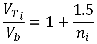
- voltage threshold level it is meant a predetermined voltage drop previously associated with a thermite reaction.
- V Ti is the voltage drop for level i threshold
- T t is the threshold current per anode for level i threshold
- N represents the number of anodes in the cell
- I is the total cell current
- K L I/y is a proportionality constant of the voltage probe.
- the different levels i may be determined experimentally based on threshold current levels per anode that are known to cause a thermite reaction or damage to the anode.
- the proportionality constant of the voltage probe K t may be calculated as a function of the material resistivity, temperature and the geometry of the voltage probe.
- the "baseline voltage” measures the voltage drop per voltage probe.
- the baseline voltage V b may be given by:
- the number of anodes per voltage probe Tii can be as many as 100. Therefore, the threshold to base voltage ratio — , can vb be as small as 1.015. Thus, the detection system should be capable of detecting a 1.5% increase in the voltage drop.
- One approach to increase the sensitivity of the detection system is by choosing a location of the voltage probes that optimizes the signal-to-noise ratio (SNR). As explained above, the voltage probes are placed as far apart as possible so that they detect larger voltage drop signals. As the noise is assumed to be constant through the anode assembly, the signal-to-noise ratio (SNR) is thus maximized.
- SNR signal-to-noise ratio
- Figure 3 shows a graphic of voltage drops for a cell comprising four anode assemblies in which one of the anode assemblies is experiencing a simulated thermite reaction.
- anode assemblies 1 and 2 were sequentially shorted (first assembly 1 then 2).
- the voltage drop of each anode assembly is independent of the voltage drops of the other anode assemblies allowing to identify the location of the anode assembly experiencing the thermite reaction.
- a targeted response can be considered in order to mitigate and, ideally, suppress the thermite reaction.
- each anode assembly may experience a different baseline voltage.
- the voltage drop has the characteristics of: having a variable baseline voltage, depending on position of anodes and their number, and depending on the overlapping dimensions of the anode and cathode (ACO). Indeed, the ACO affects the intensity of the electrical current flowing through the anode assembly. Therefore, a variation of the ACO affects the voltage drop experienced by the anode assembly. The voltage drop may also vary depending on the anode to cathode distance (ACD).
- ACD anode to cathode distance
- a thermite condition typically arises suddenly, which allows for the consideration of a number of potential signal processing techniques to enhance detectability of thermite reactions besides the direct voltage reading from the voltage probe.
- One technique is to use the time derivative of the voltage drop to indicate occurrence of a potential thermite reaction.
- a sudden voltage drop variation would produce a large spike in the derivative signal (i.e., voltage drop derivative) thereby allowing to detect a potential thermite reaction.
- Figure 4 shows a graphic of the voltage drop derivatives computed from the voltage drops of Figure 3. From Figure 4, it can be seen that a distinct voltage drop derivative initially positive, then negative is obtained for each simulated thermite reaction.
- the positive voltage drop derivative corresponds to the initial rise of the electrical current flowing through the shorted anode assembly.
- the negative voltage drop derivative corresponds to the fall of the electrical current at the end of the simulated thermite reaction.
- - 13 - is independent of the voltage drop derivative of the other anode assemblies allowing to identify the location of the thermite reaction (i.e., which anode assembly is experiencing a thermite reaction). Thus, a targeted response can be considered in order to mitigate and, ideally, suppress the thermite reaction.
- the voltage drop derivative takes into account the variation of the voltage drop rather than its magnitude. Therefore, the voltage drop derivative has a zero baseline voltage and is more sensitive to sudden changes in the voltage drop.
- Figure 5 shows a graphic of the voltage drop variance computed from the voltage drops of Figure 3.
- a voltage drop is measured for each anode assembly at each moment (or time interval).
- the variance of the voltage drop is computed for each moment (or time interval) based on the voltage drop signal.
- the signal thus obtained is the voltage drop variance.
- the voltage drop variance technique offers the benefit of tracking a single signal for the electrolytic cell instead of tracking multiple signals.
- the voltage drop variance takes into account the voltage drop of each anode assembly of the electrolytic cell. Therefore the voltage drop variance is dependent on all anode assemblies of the electrolytic cell. The voltage drop variance does not allow to identify the location of the thermite reaction.
- the voltage drop variance has the characteristics of: having a variable baseline voltage, depending on position of anodes and their number, and depending on the overlapping dimensions of the anode and cathode ACO, etc.
- a further enhancement could be to use the derivative of the variance as a signal processing technique. This technique would reliably predict a sudden change in a voltage drop even if the initial variance is high.
- Figure 6 shows a graphic of the derivative of the voltage drop variance computed from the voltage drops of Figure 3.
- Figure 6 illustrates a derivative of the voltage drop variance initially positive, then negative for each simulated thermite reaction.
- the positive derivative of the voltage drop variance corresponds to the initial rise of the electrical current flowing through the shorted anode assembly.
- the negative derivative of the voltage drop variance corresponds to the fall of the electrical current at the end of the simulated thermite reaction. In this case, the sign of the variance can be ignored since the derivative depends essentially on the rate of change.
- the derivative of the voltage drop variance takes into account the voltage drop of each anode assembly of the electrolytic cell. Therefore the derivative of the voltage drop variance is dependent on all anode assemblies of the electrolytic cell.
- the derivative of the voltage drop variance may not allow to identify the location of the thermite reaction.
- the derivative of the voltage drop variance has the advantages of having a zero baseline voltage and detecting sudden changes in the voltage drop.
- Figure 7 illustrates a detection method 200, based on voltage measurements, to anticipate and react to a potential thermite condition.
- the method 200 also allows to prevent a sustained thermite reaction.
- the method 200 takes advantage of derivative and variance terms to enhance the reliability of the voltage drop interpretation.
- the method 200 for detecting a thermite reaction in an electrolytic cell comprises measuring 210 a voltage drop for each anode assembly.
- the voltage drop corresponds to the current flow in the anode assembly.
- the voltage drop is measured using a pair of voltage probes located on the anode rod of the anode assembly.
- the method 200 also comprises computing 220 from the measured voltage drop at least one of a voltage drop derivative 221, a voltage drop variance 222 across the one or more anode assemblies, and a derivative of the voltage drop variance 223 across the one or more anode assemblies.
- the voltage drop variance and derivative of the voltage drop variance may be computed when the electrolytic cell comprises a plurality of anode assemblies.
- the method 200 may optionally further comprise fdtering 225 the voltage drop and/or fdtering the voltage drop derivative, the variance of the voltage drop, and the derivative of the voltage drop variance.
- the method 200 further comprises detecting 230 a thermite reaction when the voltage drop exceeds at least one voltage threshold level 231.
- Each voltage threshold level is a predetermined voltage drop previously associated with a thermite reaction.
- the threshold voltage levels may also be based on past operational data of the electrolytic cell. Alternatively, the threshold voltage levels may be computed from at least one of past operational data of the electrolytic cell, operation parameters, and composition of the electrolytic cell.
- detecting 230 a thermite reaction may be
- detecting 230 a thermite reaction may be performed when a variation in variance of the voltage drop across the anode assemblies occurs 232, such as for instance, when the variation in variance of the voltage drop across the anode assemblies exceeds a threshold variation.
- detecting 230 a thermite reaction may be performed when a steep variation in derivative of the voltage drop variance across the anode assemblies occurs 234, such, for instance when the variation in derivative of the voltage drop across the anode assemblies exceeds a threshold variation.
- the method 200 may optionally comprise adjusting 240 one or more operational parameters of the electrolytic cell to mitigate and, ideally, suppress the thermite reaction upon detection of the thermite reaction.
- Adjusting 240 one or more operational parameter of the electrolytic cell may comprise changing the anode to cathode overlap (ACO) of one or more anode assemblies.
- adjusting 240 one or more operational parameter of the electrolytic cell to mitigate and, ideally, suppress the thermite reaction may also comprise removing one or more anode assemblies from the electrolytic bath; changing the current supplied to at least one of the one or more anode assemblies or the electrolytic cell; changing a temperature of the electrolytic bath; and/or changing a chemistry of the electrolytic bath.
- adjusting 240 one or more operational parameters of the electrolytic cell may take into account one or more of the exceeded voltage threshold levels; the magnitude of the voltage drop; the magnitude of the voltage drop derivative; the magnitude of the variance of the voltage drop; the magnitude of the derivative of the voltage drop variance.
- the method system and electrolytic cell as disclosed herein are particularly advantageous as they allow reducing the number of voltage signals or drops necessary for detecting a thermite reaction. From preliminary tests, it is expected that the reduction may be achieved by a factor up to 10. Although the method, system and electrolytic cell as disclosed herein use fewer voltage signals or drops, fine tuning
- the system, method and electrolytic cell as disclosed herein are expected to permit reduction in maintenance and operations costs of the electrolytic cell due to a reduction in the number of signals to install and monitor.
- FIG 8 shows a logical modular representation of a system 1000 for detecting a thermite reaction in an electrolytic cell in accordance with the teachings of the present application.
- the electrolytic cell comprises at least one anode assembly of one or more metal-oxide oxide-containing anodes, at least one cathode, an electrolytic bath, and a current supply buss providing a current to the at least one anode assembly through a distinct anode rod for each anode assembly.
- the system 1000 provides an exemplary modular view of the controller 1100 involved in the detecting.
- the system 1000 may also comprise a remote monitoring station 1200.
- the controller 1100 may exchange data with the remote monitoring station 1200 and the controller 1100 is therefore able to exchange one or more message and/or one or more commands with the remote monitoring station 1200.
- the controller 1100 comprises a memory module 1120, a processor module 1130 and a network interface module 1140.
- the processor module 1130 may represent a single processor with one or more processor cores or an array of processors, each comprising one or more processor cores.
- the memory module 1120 may comprise various types of memory (different standardized or kinds of Random Access Memory (RAM) modules, memory cards, Read-Only Memory (ROM) modules, programmable ROM, etc.).
- the network interface module 1140 represents at least one physical interface that can be used to communicate with other network nodes.
- the network interface module 1140 may be made visible to the other modules of the controller 1100 through one or more logical interfaces.
- a bus 1170 is depicted as an example of means for exchanging data between the different modules of the controller 1100.
- the present invention is not affected by the way the different modules exchange information between them.
- the memory module 1120 and the processor module 1130 could be connected by a parallel bus, but could also be connected by a serial connection or involve an intermediate module (not shown) without affecting the teachings of the present invention.
- the controller 1100 may also comprise an optional Graphical User Interface (GUI) module 1150 comprising one or more display screen(s) forming a display system, for the controller 1100.
- GUI Graphical User Interface
- the display screens of the GUI module 1150 could be split into one or more flat panels, but could also be a single flat or curved screen visible from an expected user position (not shown). Skilled persons will readily understand that the GUI module 1150 may be used in a variety of contexts not limited to the previously mentioned examples.
- the system 1000 may comprise a data storage system 1500 that comprises data related to brick positioning and may further log data while the production is performed.
- Figure 8 shows examples of the storage system 1500 as a distinct database system 1500 A, a distinct module 1500B of the controller 1100 or a sub-module 1500C of the memory module 1120 of the controller 1100.
- the storage system 1500 may also comprise storage modules (not shown) on the remote monitoring station 1200.
- the storage system 1500 may be distributed over different systems A, B, C and/or the remote monitoring station 1200 or may be in a single system.
- the storage system 1500 may comprise one or more logical or physical as well as local or remote hard disk drive (HDD) (or an array thereof).
- HDD hard disk drive
- the storage system 1500 may further comprise a local or remote database made accessible to the controller 1100 by a standardized or proprietary interface or via the network interface module 1140.
- the variants of the storage system 1500 usable in the context of the present invention will be readily apparent to persons skilled in the art.
- a measurement input module 1160 and an optional control module 1161 are provided in the controller 1100.
- the measurement input module 1160 and the control module 1161 will be referred to hereinbelow as distinct logical modules, but skilled person will readily recognize that a single logical module may have been shown instead.
- an optional external input/output (I/O) module 1162 and/or an optional internal input/output (I/O) module 1164 may be provided with the measurement input module 1160 and the control module 1161.
- the external 1/ O module 1162 may be required, for instance, for interfacing with one or more robots, one or more input device (e.g., measurement probe) and/or one or more output device (e.g., printer).
- the internal input/output (I/O) module 1164 may be required, for instance, for interfacing the controller 1100 with one or more instruments or controls (not shown) typically used in the context of electrolysis cell control (e.g., probes).
- the I/O module 1164 may comprise necessary interface(s) to exchange data, set data or get data from such instruments or controls.
- the measurement input module 1160 and processor module 1130 are tightly related to the detection of the thermite reaction.
- the measurement input module 1160 and the processor module 1130 may be involved in various step of a method 200 described hereinabove.
Landscapes
- Chemical & Material Sciences (AREA)
- Engineering & Computer Science (AREA)
- Chemical Kinetics & Catalysis (AREA)
- Electrochemistry (AREA)
- Materials Engineering (AREA)
- Metallurgy (AREA)
- Organic Chemistry (AREA)
- Electrolytic Production Of Metals (AREA)
- Electrolytic Production Of Non-Metals, Compounds, Apparatuses Therefor (AREA)
- Catalysts (AREA)
- Hybrid Cells (AREA)
Abstract
Description



Claims
Priority Applications (8)
| Application Number | Priority Date | Filing Date | Title |
|---|---|---|---|
| EP21884216.9A EP4237838A4 (en) | 2020-10-28 | 2021-10-27 | Detecting thermite reactions in an electrolytic cell |
| BR112023005871A BR112023005871A2 (en) | 2020-10-28 | 2021-10-27 | DETECT THERMITE REACTIONS IN AN ELECTROLYTIC CELL |
| US18/029,805 US20230374685A1 (en) | 2020-10-28 | 2021-10-27 | Detecting thermite reactions in an electrolytic cell |
| CA3193088A CA3193088A1 (en) | 2020-10-28 | 2021-10-27 | Detecting thermite reactions in an electrolytic cell |
| AU2021371450A AU2021371450A1 (en) | 2020-10-28 | 2021-10-27 | Detecting thermite reactions in an electrolytic cell |
| CN202180072431.7A CN116457503A (en) | 2020-10-28 | 2021-10-27 | Detecting thermite reactions in electrolytic cells |
| ZA2023/04413A ZA202304413B (en) | 2020-10-28 | 2023-04-13 | Detecting thermite reactions in an electrolytic cell |
| DKPA202370247A DK202370247A1 (en) | 2020-10-28 | 2023-05-23 | Detecting thermite reactions in an electrolytic cell |
Applications Claiming Priority (2)
| Application Number | Priority Date | Filing Date | Title |
|---|---|---|---|
| US202063106517P | 2020-10-28 | 2020-10-28 | |
| US63/106,517 | 2020-10-28 |
Publications (1)
| Publication Number | Publication Date |
|---|---|
| WO2022087732A1 true WO2022087732A1 (en) | 2022-05-05 |
Family
ID=81381935
Family Applications (1)
| Application Number | Title | Priority Date | Filing Date |
|---|---|---|---|
| PCT/CA2021/051512 Ceased WO2022087732A1 (en) | 2020-10-28 | 2021-10-27 | Detecting thermite reactions in an electrolytic cell |
Country Status (10)
| Country | Link |
|---|---|
| US (1) | US20230374685A1 (en) |
| EP (1) | EP4237838A4 (en) |
| CN (1) | CN116457503A (en) |
| AU (1) | AU2021371450A1 (en) |
| BR (1) | BR112023005871A2 (en) |
| CA (1) | CA3193088A1 (en) |
| DK (1) | DK202370247A1 (en) |
| PY (1) | PY2195200A (en) |
| WO (1) | WO2022087732A1 (en) |
| ZA (1) | ZA202304413B (en) |
Citations (1)
| Publication number | Priority date | Publication date | Assignee | Title |
|---|---|---|---|---|
| US20140048421A1 (en) * | 2012-08-17 | 2014-02-20 | Alcoa Inc. | Systems and methods for preventing thermite reactions in electrolytic cells |
Family Cites Families (8)
| Publication number | Priority date | Publication date | Assignee | Title |
|---|---|---|---|---|
| US3888747A (en) * | 1972-10-18 | 1975-06-10 | Nat Southwire Aluminum | Method of and apparatus for producing metal |
| JPS57181390A (en) * | 1981-04-28 | 1982-11-08 | Mitsubishi Keikinzoku Kogyo Kk | Measuring method for counter electromotive force of aluminum electrolytic cell |
| FR2529913A1 (en) * | 1982-07-07 | 1984-01-13 | Chloe Chemie | DEVICE FOR MONITORING AND DISPLAYING POWER DISTRIBUTION IN AN ELECTROLYSER |
| RU2359072C1 (en) * | 2007-10-29 | 2009-06-20 | Александр Иванович Громыко | Method of informational parametres pickup of aluminium electrolysers |
| CN102443821A (en) * | 2010-10-15 | 2012-05-09 | 杜金宝 | Liquid level fluctuation monitoring device |
| CN201908142U (en) * | 2010-12-17 | 2011-07-27 | 高德金 | Control and adjustment device for continuous testing for aluminum electrolysis cell |
| CA2894555C (en) * | 2012-12-31 | 2017-11-28 | Alcoa Inc. | Methods for determining green electrode electrical resistivity and methods for making electrodes |
| CN107604388B (en) * | 2017-09-11 | 2023-08-08 | 昆明理工恒达科技股份有限公司 | Composite anode material and its preparation method, anode plate and its preparation method |
-
2021
- 2021-10-27 US US18/029,805 patent/US20230374685A1/en active Pending
- 2021-10-27 CN CN202180072431.7A patent/CN116457503A/en active Pending
- 2021-10-27 EP EP21884216.9A patent/EP4237838A4/en active Pending
- 2021-10-27 WO PCT/CA2021/051512 patent/WO2022087732A1/en not_active Ceased
- 2021-10-27 BR BR112023005871A patent/BR112023005871A2/en unknown
- 2021-10-27 AU AU2021371450A patent/AU2021371450A1/en active Pending
- 2021-10-27 CA CA3193088A patent/CA3193088A1/en active Pending
- 2021-10-28 PY PY202102195200A patent/PY2195200A/en unknown
-
2023
- 2023-04-13 ZA ZA2023/04413A patent/ZA202304413B/en unknown
- 2023-05-23 DK DKPA202370247A patent/DK202370247A1/en unknown
Patent Citations (2)
| Publication number | Priority date | Publication date | Assignee | Title |
|---|---|---|---|---|
| US20140048421A1 (en) * | 2012-08-17 | 2014-02-20 | Alcoa Inc. | Systems and methods for preventing thermite reactions in electrolytic cells |
| US9982355B2 (en) | 2012-08-17 | 2018-05-29 | Alcoa Usa Corp. | Systems and methods for preventing thermite reactions in electrolytic cells |
Non-Patent Citations (1)
| Title |
|---|
| See also references of EP4237838A4 |
Also Published As
| Publication number | Publication date |
|---|---|
| EP4237838A1 (en) | 2023-09-06 |
| ZA202304413B (en) | 2025-04-30 |
| EP4237838A4 (en) | 2025-06-18 |
| CN116457503A (en) | 2023-07-18 |
| AU2021371450A1 (en) | 2023-06-01 |
| CA3193088A1 (en) | 2022-05-05 |
| PY2195200A (en) | 2022-05-30 |
| BR112023005871A2 (en) | 2023-05-09 |
| US20230374685A1 (en) | 2023-11-23 |
| AU2021371450A9 (en) | 2024-05-02 |
| DK202370247A1 (en) | 2023-06-09 |
Similar Documents
| Publication | Publication Date | Title |
|---|---|---|
| US6136177A (en) | Anode and cathode current monitoring | |
| AU2014222569B2 (en) | Measurement of electric current in an individual electrode in an electrolysis system | |
| JP4141841B2 (en) | Sensor array and method for electrochemical corrosion monitoring | |
| AU2016204619B2 (en) | Arrangement for measuring electric current in an individual electrode in an electrolysis system | |
| US20230374685A1 (en) | Detecting thermite reactions in an electrolytic cell | |
| US12006581B2 (en) | Systems and methods for preventing thermite reactions in electrolytic cells | |
| JPH10245690A (en) | Detection of abnormality of electrolytic smelting and abnormality detection system for executing the same | |
| WO2014032084A1 (en) | Magnetic shielding for measuring a plurality of input and/or output currents to an electrolytic cell | |
| Mejia et al. | Methodological Approaches to Troubleshooting and Enhancing Molten Salt Electrochemical Experiments | |
| JP3371443B2 (en) | Short circuit detection method | |
| JP2003160893A (en) | Control method of electrolytic cell voltage |
Legal Events
| Date | Code | Title | Description |
|---|---|---|---|
| 121 | Ep: the epo has been informed by wipo that ep was designated in this application |
Ref document number: 21884216 Country of ref document: EP Kind code of ref document: A1 |
|
| ENP | Entry into the national phase |
Ref document number: 3193088 Country of ref document: CA |
|
| REG | Reference to national code |
Ref country code: BR Ref legal event code: B01A Ref document number: 112023005871 Country of ref document: BR |
|
| WWE | Wipo information: entry into national phase |
Ref document number: 202180072431.7 Country of ref document: CN |
|
| ENP | Entry into the national phase |
Ref document number: 112023005871 Country of ref document: BR Kind code of ref document: A2 Effective date: 20230329 |
|
| WWE | Wipo information: entry into national phase |
Ref document number: PA202370247 Country of ref document: DK |
|
| WWE | Wipo information: entry into national phase |
Ref document number: 202317036277 Country of ref document: IN |
|
| NENP | Non-entry into the national phase |
Ref country code: DE |
|
| ENP | Entry into the national phase |
Ref document number: 2021371450 Country of ref document: AU Date of ref document: 20211027 Kind code of ref document: A |
|
| ENP | Entry into the national phase |
Ref document number: 2021884216 Country of ref document: EP Effective date: 20230530 |
|
| WWE | Wipo information: entry into national phase |
Ref document number: 523440346 Country of ref document: SA |
|
| WWE | Wipo information: entry into national phase |
Ref document number: 523440346 Country of ref document: SA |
|
| WWE | Wipo information: entry into national phase |
Ref document number: 523440346 Country of ref document: SA |