WO2022088265A1 - 一种变流器直流回路异常的监控方法及装置 - Google Patents
一种变流器直流回路异常的监控方法及装置 Download PDFInfo
- Publication number
- WO2022088265A1 WO2022088265A1 PCT/CN2020/128343 CN2020128343W WO2022088265A1 WO 2022088265 A1 WO2022088265 A1 WO 2022088265A1 CN 2020128343 W CN2020128343 W CN 2020128343W WO 2022088265 A1 WO2022088265 A1 WO 2022088265A1
- Authority
- WO
- WIPO (PCT)
- Prior art keywords
- current
- monitoring method
- loop
- value
- circuit
- Prior art date
- Legal status (The legal status is an assumption and is not a legal conclusion. Google has not performed a legal analysis and makes no representation as to the accuracy of the status listed.)
- Ceased
Links
Images



Classifications
-
- G—PHYSICS
- G01—MEASURING; TESTING
- G01R—MEASURING ELECTRIC VARIABLES; MEASURING MAGNETIC VARIABLES
- G01R31/00—Arrangements for testing electric properties; Arrangements for locating electric faults; Arrangements for electrical testing characterised by what is being tested not provided for elsewhere
- G01R31/28—Testing of electronic circuits, e.g. by signal tracer
- G01R31/282—Testing of electronic circuits specially adapted for particular applications not provided for elsewhere
-
- G—PHYSICS
- G01—MEASURING; TESTING
- G01R—MEASURING ELECTRIC VARIABLES; MEASURING MAGNETIC VARIABLES
- G01R31/00—Arrangements for testing electric properties; Arrangements for locating electric faults; Arrangements for electrical testing characterised by what is being tested not provided for elsewhere
- G01R31/28—Testing of electronic circuits, e.g. by signal tracer
- G01R31/2801—Testing of printed circuits, backplanes, motherboards, hybrid circuits or carriers for multichip packages [MCP]
- G01R31/281—Specific types of tests or tests for a specific type of fault, e.g. thermal mapping, shorts testing
- G01R31/2813—Checking the presence, location, orientation or value, e.g. resistance, of components or conductors
-
- G—PHYSICS
- G01—MEASURING; TESTING
- G01R—MEASURING ELECTRIC VARIABLES; MEASURING MAGNETIC VARIABLES
- G01R31/00—Arrangements for testing electric properties; Arrangements for locating electric faults; Arrangements for electrical testing characterised by what is being tested not provided for elsewhere
- G01R31/28—Testing of electronic circuits, e.g. by signal tracer
- G01R31/2832—Specific tests of electronic circuits not provided for elsewhere
- G01R31/2836—Fault-finding or characterising
- G01R31/2843—In-circuit-testing
-
- G—PHYSICS
- G01—MEASURING; TESTING
- G01R—MEASURING ELECTRIC VARIABLES; MEASURING MAGNETIC VARIABLES
- G01R31/00—Arrangements for testing electric properties; Arrangements for locating electric faults; Arrangements for electrical testing characterised by what is being tested not provided for elsewhere
- G01R31/40—Testing power supplies
-
- H—ELECTRICITY
- H02—GENERATION; CONVERSION OR DISTRIBUTION OF ELECTRIC POWER
- H02M—APPARATUS FOR CONVERSION BETWEEN AC AND AC, BETWEEN AC AND DC, OR BETWEEN DC AND DC, AND FOR USE WITH MAINS OR SIMILAR POWER SUPPLY SYSTEMS; CONVERSION OF DC OR AC INPUT POWER INTO SURGE OUTPUT POWER; CONTROL OR REGULATION THEREOF
- H02M1/00—Details of apparatus for conversion
- H02M1/32—Means for protecting converters other than automatic disconnection
-
- H—ELECTRICITY
- H02—GENERATION; CONVERSION OR DISTRIBUTION OF ELECTRIC POWER
- H02M—APPARATUS FOR CONVERSION BETWEEN AC AND AC, BETWEEN AC AND DC, OR BETWEEN DC AND DC, AND FOR USE WITH MAINS OR SIMILAR POWER SUPPLY SYSTEMS; CONVERSION OF DC OR AC INPUT POWER INTO SURGE OUTPUT POWER; CONTROL OR REGULATION THEREOF
- H02M5/00—Conversion of AC power input into AC power output, e.g. for change of voltage, for change of frequency, for change of number of phases
- H02M5/40—Conversion of AC power input into AC power output, e.g. for change of voltage, for change of frequency, for change of number of phases with intermediate conversion into DC
- H02M5/42—Conversion of AC power input into AC power output, e.g. for change of voltage, for change of frequency, for change of number of phases with intermediate conversion into DC by static converters
- H02M5/44—Conversion of AC power input into AC power output, e.g. for change of voltage, for change of frequency, for change of number of phases with intermediate conversion into DC by static converters using discharge tubes or semiconductor devices to convert the intermediate DC into AC
- H02M5/453—Conversion of AC power input into AC power output, e.g. for change of voltage, for change of frequency, for change of number of phases with intermediate conversion into DC by static converters using discharge tubes or semiconductor devices to convert the intermediate DC into AC using devices of a triode or transistor type requiring continuous application of a control signal
- H02M5/458—Conversion of AC power input into AC power output, e.g. for change of voltage, for change of frequency, for change of number of phases with intermediate conversion into DC by static converters using discharge tubes or semiconductor devices to convert the intermediate DC into AC using devices of a triode or transistor type requiring continuous application of a control signal using semiconductor devices only
- H02M5/4585—Conversion of AC power input into AC power output, e.g. for change of voltage, for change of frequency, for change of number of phases with intermediate conversion into DC by static converters using discharge tubes or semiconductor devices to convert the intermediate DC into AC using devices of a triode or transistor type requiring continuous application of a control signal using semiconductor devices only having a rectifier with controlled elements
Definitions
- the invention relates to the control field of power electronic converters, in particular to the detection of DC circuit parameter deviation in a traction converter.
- Traction converters are widely used.
- their topology is generally AC-DC-AC type converters, one end of which is AC input, the other end is AC output, and the intermediate link is DC loop, which can realize energy
- its topology is generally an AC-DC converter, one end of which is an AC input and the other end is a DC link, which can also achieve two-way flow of energy; in the field of urban rail, its topology It is generally a DC type converter, one end of which is a DC input and the other end is an AC output.
- high-power converters are widely used in traction drive, DC transmission, electric vehicles, new energy and other fields. mechanical energy.
- the high-power traction converter provides power for the train and is the "heart" of the train, and its reliability directly determines the reliability of the train's operation.
- the traction converter as the core equipment that converts electrical energy into mechanical energy, also has very bad operating conditions.
- the input terminal is connected to the AC grid.
- the voltage, current and harmonics from the AC grid are a severe test for the converter.
- the wheel-rail connection from the load side will also bring great stress to the converter of the locomotive. Power shock. From the macro level of the locomotive, it seems that the traction power is output smoothly, but at the converter level, the real-time changes of current and voltage are happening all the time.
- the DC link is crucial for the smoothness of power transfer.
- the intermediate circuit also includes a resonant circuit, which has a good absorption effect on the double-frequency pulsating power input from the AC input side, so as to maintain the stability of the DC voltage and keep the DC voltage low. Amplitude pulsation.
- problems such as capacitor bulging, capacitor bursting, and capacitor capacitance attenuation often occur, which affect the smooth operation of the DC circuit and the traction converter, thereby affecting the smooth operation of the entire locomotive.
- the capacitor has certain signs before the problem occurs, but due to the lack of effective means to carry out online warning, the repair and treatment will not be carried out until the capacitor bursts and causes bad influence.
- this One aspect of the invention provides a method for monitoring an abnormality of a DC loop of a converter, including:
- determining the input current further includes:
- the input current is calculated according to the AC input current and the switching function of each switch tube in the rectifier.
- determining the above-mentioned input current further includes:
- the DC current flowing into the above-mentioned DC loop is collected as the above-mentioned input current.
- determining the output current in response to an inverter being provided at the rear end of the DC loop, determining the output current further includes:
- the output current is calculated according to the AC output current and the switching function of each switch tube in the inverter.
- determining that the above-mentioned output current further includes:
- calculating the above theoretical value further includes:
- the above-mentioned theoretical value is calculated based on the above-mentioned specific sub-frequency domain component and the above-mentioned theoretical value of the total impedance.
- calculating the above actual value further includes:
- the foregoing specific sub-frequency domain component is a secondary frequency domain component.
- judging whether the above-mentioned DC loop is abnormal further includes:
- the above monitoring method further includes:
- Determining whether the above-mentioned DC loop is abnormal further includes:
- the above monitoring method further includes:
- an alarm signal is output to prompt that the converter needs to be repaired.
- the above monitoring method further includes:
- an alarm signal is output to prompt that the converter needs to be repaired.
- determining the foregoing theoretical value of the total impedance further includes:
- Another aspect of the present invention also provides a device for monitoring the abnormality of a DC loop of a converter, which specifically includes: a processor, a memory, and a computer program stored in the memory and running on the processor, the processor being configured to : execute the steps of the monitoring method described in any one of the above embodiments.
- Another aspect of the present invention also provides a computer-readable storage medium on which a computer program is stored. Specifically, when the computer program is executed by a processor, the steps of the monitoring method described in any of the above embodiments are implemented.
- the present invention is suitable for converters of different topological forms, such as AC-orthogonal type, AC-orthogonal type, orthogonal type, etc., can be widely used in different fields, and has wide adaptability.
- Another advantage of the present invention is that the method proposed by the present invention is convenient for engineering implementation, and does not need to add new sensors. It only improves the intelligence level of the processing method (algorithm) without adding additional hardware costs. value.
- FIG. 1 shows a flowchart of a method for monitoring an abnormality of a DC circuit of a converter provided by an aspect of the present invention.
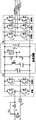
- FIG. 2 shows a schematic diagram of the circuit topology of the AC-DC-AC converter to which the monitoring method provided by the present invention is applicable.
- FIG. 3 shows a schematic diagram of the trigger pulse G i of any bridge arm in the AC loop.
- FIG. 4 shows a schematic structural diagram of the device for monitoring the abnormality of the DC circuit of the converter provided by another aspect of the present invention.
- FIG. 1 shows a schematic flowchart of an embodiment of the monitoring method described above. As shown in FIG. 1 ,
- the above monitoring method includes: step S100: determining the theoretical value of the total impedance of the DC circuit; step S200: determining the input current, output current and actual voltage of the DC circuit at the current moment; step S300: according to the input current and Calculate the theoretical value of the specific sub-frequency domain component of the DC voltage at the current moment from the current difference between the output currents and the theoretical value of the total impedance; Step S400: Calculate the actual value of the specific sub-frequency domain component of the DC voltage according to the actual voltage; and Step S500: Based on The theoretical value and the actual value determine whether the DC circuit is abnormal.
- the AC-DC converter includes an AC input side, a DC loop and an AC output side.
- the above-mentioned AC input side includes a four-quadrant converter composed of a bridge arm 1 and a bridge arm 2, and the four-quadrant converter is used as a rectifier.
- the above-mentioned AC output side includes a traction inverter composed of a bridge arm 3, a bridge arm 4, and a bridge arm 5, and is used as an inverter.
- circuit topology of the AC-DC-AC type converter shown in FIG. 2 is a schematic diagram of the most complete structure among conventional converters.
- the circuit topology correspondingly does not include the AC output side at the back end, that is, the DC loop is the output end of the converter.
- the circuit topology correspondingly does not include the AC input side of the front end, that is, the DC loop is the input end of the converter.
- the switch tubes T 1 and T 2 form the bridge arm 1
- the switch tubes T 3 and T 4 form the bridge arm 2
- the switch tubes T 5 and T 6 form the bridge arm.
- the switch tubes T7 and T8 form the bridge arm 4
- the switch tubes T9 and T10 form the bridge arm 5 .
- G 1 to G 5 respectively represent the trigger pulses of the switches of the bridge arm 1 to the bridge arm 5 in FIG. It can be understood that, for other topological structures, the switching functions G i corresponding to the topological structures can be obtained.
- FIG. 3 Please refer to FIG. 3 to understand the schematic diagram of the pulse triggering of any bridge arm corresponding to the switching function G i in the formula (1).
- U N is the AC side input voltage
- I 1 is the AC side input current
- I 2 is the AC side U-phase output current
- I 3 is the AC side V-phase output current
- I 4 is the AC side W-phase output current.
- the part where the front end of the converter is connected to the grid also includes: a charging resistor R 1 , a charging contactor K 1 and a shorting contactor K 2 . All of the above I 1 -I 4 can be acquired through current sensor acquisition, corresponding to step S200 . Optionally, only any two of the currents I 2 -I 4 of the three-phase inverter may be collected, and the third current may be calculated from the collected two currents. After collecting the currents I 1 -I 4 , the output current (DC current) of the rectifier and the input current (DC current) of the inverter can be calculated by formula (2) listed below.
- the DC loop includes: a support capacitor C d , a voltage dividing resistor R 2 and a voltage dividing resistor R 3 .
- the DC loop further includes a resonance branch, specifically including a resonance capacitor C 2 and the resonant inductance L 2 .
- U d1 is a direct current voltage, which is acquired through acquisition by a voltage sensor, corresponding to step S200.
- U d2 is the half-intermediate DC voltage.
- the output current I d1 of the rectifier is the input current of the DC side
- the input current I d2 of the inverter is the output current of the DC side.
- the difference between the input current I d1 and the output current I d2 is the current flowing into the DC loop impedance network, and the voltage formed by this current on the DC loop impedance network is the DC voltage U d1 .
- the monitoring method provided by the present invention is applicable to various forms of converters.
- the output current I d1 of the rectifier is the input current of the DC side
- the input current I d2 of the inverter is the output current of the DC side. Therefore, the input current of the DC circuit can be calculated by formula 2. I d1 and output current I d2 .
- I d1 and output current I d2 it is necessary to further determine the input current I d1 and the output current I d2 of the DC loop.
- the input current I d1 it is first possible to determine whether the front end of the DC loop is provided with a rectifier. If the front end of the DC loop is provided with a rectifier, then the input current I d1 is the output current of the rectifier, which can be obtained by formula 2. If the front end of the DC loop is not provided with a rectifier, a current sensor needs to be used to collect the DC current flowing into the DC loop as the input current I d1 .
- the output current I d2 it can be first determined whether there is an inverter at the back end of the DC circuit. If there is an inverter at the back end of the DC circuit, the output current I d2 is the input current of the inverter. obtained by formula 2. If the rear end of the DC loop is not provided with an inverter, the output current I d2 is directly determined to be zero.
- the input current I d2 and the output current I d2 of the DC circuit can be obtained, then the input current of the DC circuit can be obtained.
- the difference between the current and the output current is:
- the initially designed theoretical value Z n can be calculated according to the topology.
- Equation 4 Equation 4
- the total impedance of the DC loop can be obtained by using a formula similar to formula 4, corresponding to step S100. If the support capacitor, resonant inductance, resonant capacitor, and other stray parameters in the DC loop are not considered, the total impedance can also be calculated with a formula similar to Equation 4.
- the theoretical value of the total impedance Z n of the DC loop is a value that can be determined after the topology of the DC loop is determined, that is, the total impedance Z n is a constant, therefore, in the above step S100, you can The theoretical value of the total impedance of the DC circuit can be determined by calculating the total impedance Z n according to formula 4, and the theoretical value of the total impedance of the DC circuit can also be determined by obtaining the stored pre-calculated total impedance Z n .
- step S100 and step S200 may be replaced, and the execution order of these two steps should not unduly limit the protection scope of the present invention.
- ⁇ I d is a time domain component, and a specific sub-frequency domain component in ⁇ I d can be extracted by a general fast Fourier algorithm. It should be noted that those skilled in the art can use other algorithms to extract specific sub-frequency domain components in ⁇ I d .
- the general fast Fourier algorithm described above is only for illustration, and the protection scope of the present invention should not be unduly limited.
- the secondary frequency domain component ⁇ I d2 in ⁇ I d is selected to be extracted. It can be understood that the magnitude of the secondary frequency domain component ⁇ I d2 in ⁇ I d is larger, which can make abnormal monitoring more sensitive.
- the secondary frequency domain component of the DC voltage can be calculated as:
- the calculated DC voltage is also the secondary frequency domain component of the DC voltage.
- other specific frequency domain components of the DC voltage can be calculated accordingly.
- step S300 can already be implemented, namely calculating the theoretical value of the specific sub-frequency domain component of the DC voltage at the current moment according to the current difference between the input current and the output current and the theoretical value of the total impedance.
- Z n is the total design impedance of the DC circuit, which is set at the beginning of the converter design.
- Z n is the total design impedance of the DC circuit, which is set at the beginning of the converter design.
- the actual value Z' n of the total impedance of the DC circuit deviates from the design value Z n .
- the secondary frequency domain components ⁇ U' d2 and Z' n of the actual DC voltage should meet the following conditions:
- the deviation between the actual total impedance and the theoretical total impedance can be determined by comparing the actual DC voltage with the theoretical DC voltage.
- the abnormal situation of the DC circuit can be reflected.
- the secondary component ⁇ U' d2 can be extracted by performing Fourier analysis on the DC voltage U d1 collected in step S200 , corresponding to step S400 .
- the above-mentioned threshold value ⁇ U dg may be a preset constant threshold value.
- the above-mentioned threshold value ⁇ U dg may also be a variable value according to ⁇ U d2m . If it is a variable value, it can represent Whether the ratio between the actual values in the theoretical range is out of the preset range. It can be understood that those skilled in the art can set different comparison methods according to the actual situation, so as to judge the deviation between the theoretical value and the actual value of the secondary component of the DC voltage, and then reflect the difference of the total impedance of the DC circuit. The deviation between the actual values in the theoretical range, thus characterizing whether the DC circuit is abnormal.
- the high-frequency harmonics caused by the switching of the rectifier or the inverter cannot have a great influence on the monitoring results. It can be ignored in the method of the present invention, so the monitoring result can reliably monitor the abnormality of the parameters of the DC circuit.
- the monitoring method provided by the present invention further comprises the above-mentioned theoretical value ⁇ U d2m and actual value.
- ⁇ U' d2m is subjected to low-pass filtering. As a result, the noise disturbance of the theoretical value ⁇ U d2m and the actual value ⁇ U' d2m can be reduced.
- the monitoring method further includes: in response to determining that the DC circuit is abnormal, outputting an alarm signal to prompt that the converter needs to be repaired.
- a counter can also be set, and the corresponding count value is M.
- M is incremented by 1.
- the threshold value N of the count value can be set.
- the monitoring method provided by the invention can monitor the pulsation of the DC voltage in real time under the normal working state of the converter, and by effectively distinguishing the normal pulsation and the abnormal pulsation of the DC voltage, when it is found that the parameters of the DC circuit are obviously abnormal, it can be timely Early warning, prompting after-sales service personnel to conduct maintenance and investigation, can effectively avoid serious failure of the locomotive, and is a method with engineering application value.
- FIG. 4 shows the monitoring device for the abnormality of the DC loop of the converter provided by another aspect of the present invention.
- FIG. 4 shows the monitoring device for the abnormality of the DC loop of the converter provided by another aspect of the present invention.
- FIG. 4 shows the monitoring device for the abnormality of the DC loop of the converter provided by another aspect of the present invention.
- FIG. 4 shows the monitoring device for the abnormality of the DC loop of the converter provided by another aspect of the present invention.
- FIG. 4 shows the monitoring device for the abnormality of the DC loop of the converter provided by another aspect of the present invention.
- FIG. 4 shows the monitoring device for the abnormality of the DC loop of the converter provided by another aspect of the present invention.
- FIG. 4 shows the monitoring device for the abnormality of the DC loop of the converter provided by another aspect of the present invention.
- FIG. 4 shows the monitoring device for the abnormality of the DC loop of the converter provided by another aspect of the present invention.
- FIG. 4 shows the monitoring device for the abnormality of the DC loop of the converter provided by another aspect
- Another aspect of the present invention also provides a computer storage medium on which a computer program is stored.
- the computer program is executed by a processor, the steps of the above-mentioned method for monitoring the abnormality of the DC circuit of the converter are realized.
- the monitoring method for the abnormality of the DC loop of the converter will not be repeated here.
- the present invention is suitable for converters of different topological forms, such as AC-orthogonal type, AC-orthogonal type, orthogonal type, etc., can be widely used in different fields, and has wide adaptability.
- Another advantage of the present invention is that the method proposed by the present invention is convenient for engineering implementation, and does not need to add new sensors. It only improves the intelligence level of the processing method (algorithm) without adding additional hardware costs. value.
- DSPs digital signal processors
- ASICs application specific integrated circuits
- FPGAs field programmable gate arrays
- a general-purpose processor may be a microprocessor, but in the alternative, the processor may be any conventional processor, controller, microcontroller, or state machine.
- a processor may also be implemented as a combination of computing devices, such as a combination of a DSP and a microprocessor, multiple microprocessors, one or more microprocessors cooperating with a DSP core, or any other such configuration.
- a software module may reside in RAM memory, flash memory, ROM memory, EPROM memory, EEPROM memory, registers, hard disk, removable disk, CD-ROM, or any other form of storage medium known in the art.
- An exemplary storage medium is coupled to the processor such the processor can read information from, and write information to, the storage medium.
- the storage medium may be integrated into the processor.
- the processor and storage medium may reside in the ASIC.
- the ASIC may reside in the user terminal.
- the processor and storage medium may reside in the user terminal as discrete components.
- the functions described may be implemented in hardware, software, firmware, or any combination thereof. If implemented in software as a computer program product, the functions may be stored on or transmitted over as one or more instructions or code on a computer-readable medium.
- Computer-readable media includes both computer storage media and communication media including any medium that facilitates transfer of a computer program from one place to another.
- a storage medium can be any available medium that can be accessed by a computer.
- such computer-readable media may include RAM, ROM, EEPROM, CD-ROM or other optical disk storage, magnetic disk storage, or other magnetic storage devices, or can be used to carry or store instructions or data structures in the form of Any other medium that conforms to program code and that can be accessed by a computer.
- any connection is properly termed a computer-readable medium.
- the software is transmitted from a web site, server, or other remote source using coaxial cable, fiber optic cable, twisted pair, digital subscriber line (DSL), or wireless technologies such as infrared, radio, and microwave
- coaxial cable, fiber optic cable, twisted pair, DSL, or wireless technologies such as infrared, radio, and microwave
- Disk and disc includes compact disc (CD), laser disc, optical disc, digital versatile disc (DVD), floppy disk and blu-ray disc, where disks are often reproduced magnetically data, and discs reproduce the data optically with a laser. Combinations of the above should also be included within the scope of computer-readable media.
Landscapes
- Engineering & Computer Science (AREA)
- Physics & Mathematics (AREA)
- General Physics & Mathematics (AREA)
- General Engineering & Computer Science (AREA)
- Power Engineering (AREA)
- Computer Hardware Design (AREA)
- Microelectronics & Electronic Packaging (AREA)
- Rectifiers (AREA)
- Inverter Devices (AREA)
Abstract
一种变流器直流回路异常的监控方法及装置。上述监控方法包括:确定上述直流回路的总阻抗理论值(S100);确定当前时刻上述直流回路的输入电流、输出电流和实际电压(S200);根据上述输入电流和输出电流之间的电流差值和上述总阻抗理论值计算当前时刻直流电压特定次频域分量的理论值(S300);根据上述实际电压计算直流电压特定次频域分量的实际值(S400);以及基于上述理论值与上述实际值判断上述直流回路是否异常(S500)。还提供了实现上述监控方法的监控装置。该监控方法与装置,能够实现直流回路参数异常的在线预警,从而能够在直流回路正常工作的同时实时监控直流回路的状态,以及时发现直流回路的参数异常,从而能够实现异常的在线预警。
Description
本发明涉及电力电子变流器的控制领域,尤其涉及一种牵引变流器中直流回路参数偏差的检测。
牵引变流器的应用非常广泛,在机车、动车组等相关领域,其拓扑一般是交直交型变流器,其一端为交流输入,另一端为交流输出,中间环节为直流回路,能够实现能量的双向流动;在电力系统、直流输电等领域,其拓扑一般是交直型变流器,其一端为交流输入,另一端为直流环节,同样能够实现能量的双向流动;在城轨领域,其拓扑一般是直交型变流器,其一端为直流输入,另一端为交流输出。
这些不同类型的大功率变流器,广泛应用在牵引传动、直流输电、电动汽车、新能源等领域,这些变流器的主要作用是将电网上的电能进行传送,一般是将电能转变为电机的机械能。大功率的牵引变流器为列车提供功率,是列车的“心脏”,其可靠性直接决定了列车运行的可靠性。
列车在实际运行过程中,运行工况十分恶劣,牵引变流器作为将电能变换为机械能的核心设备,其运行工况同样十分恶劣。其输入端与交流电网相连,来自交流电网的电压、电流及谐波对变流器来说一种严苛的考验,来自负载端的轮轨连接也会给机车的变流器带来很大的功率冲击。从机车这个宏观的层面来看,看似平稳地输出着牵引功率,而在变流器层面,电流和电压的实时改变却无时不刻都在发生着。作为功率流动的缓冲环节,直流回路对于功率传递的平稳性至关重要。
直流环节的支撑电容对功率的稳定流动起到至关重要的作用。在很多机车牵引系统中,中间回路还包括谐振回路,其对交流输入侧输入的二倍频脉动功率有较好的吸收作用,从而能够很好的维持直流电压的稳定,使直流电压保持较低幅值的脉动。牵引变流器在长期的运行后,常常发生电容器鼓包、电容器炸裂、电容器容值衰减等问题,影响直流回路、牵引变流器的平稳运行,从而影响整列机车的平稳运行。有时候电容器在发生问题之前已经有一定的征兆,但是由于缺乏有效手段进行在线预警,直到电容器发生鼓包炸裂造成恶劣的影响后才进行维修处理。
因此,希望能够提供一种变流器直流回路异常的监控方法及装置,能够在直流回路所发生的问题在还未造成如电容器鼓包炸裂的恶劣影响前提前监控直流回路的状 态,及时进行预警,防止直流回路所发生的问题进一步扩大造成事故。
发明内容
以下给出一个或多个方面的简要概述以提供对这些方面的基本理解。此概述不是所有构想到的方面的详尽综览,并且既非旨在指认出所有方面的关键性或决定性要素亦非试图界定任何或所有方面的范围。其唯一的目的是要以简化形式给出一个或多个方面的一些概念以为稍后给出的更加详细的描述之序。
如上所描述的,为了能够在直流回路所发生的问题在还未造成如电容器鼓包炸裂的恶劣影响前提前监控直流回路的状态,及时进行预警,防止直流回路所发生的问题进一步扩大造成事故,本发明的一方面提供了一种变流器直流回路异常的监控方法,包括:
确定上述直流回路的总阻抗理论值;
确定当前时刻上述直流回路的输入电流、输出电流和实际电压;
根据上述输入电流和输出电流之间的电流差值和上述总阻抗理论值计算当前时刻直流电压特定次频域分量的理论值;
根据上述实际电压计算直流电压特定次频域分量的实际值;以及
基于上述理论值与上述实际值判断上述直流回路是否异常。
在上述监控方法的一实施例中,可选的,响应于上述直流回路的前端设有整流器,确定上述输入电流进一步包括:
采集上述整流器的交流输入电流;
获取上述整流器中各开关管的开关函数;以及
根据上述交流输入电流和上述整流器中各开关管的开关函数计算上述输入电流。
在上述监控方法的一实施例中,可选的,响应于上述直流回路为上述变流器的输入端,确定上述输入电流进一步包括:
采集流入上述直流回路的直流电流为上述输入电流。
在上述监控方法的一实施例中,可选的,响应于上述直流回路的后端设有逆变器,确定上述输出电流进一步包括:
采集上述逆变器的交流输出电流;
获取上述逆变器中各开关管的开关函数;以及
根据上述交流输出电流和上述逆变器中各开关管的开关函数计算上述输出电流。
在上述监控方法的一实施例中,可选的,响应于上述直流回路为上述变流器的输 出端,确定上述输出电流进一步包括:
确定上述输出电流为零。
在上述监控方法的一实施例中,可选的,计算上述理论值进一步包括:
采用通用快速傅立叶算法提取上述电流差值的特定次频域分量;以及
基于上述特定次频域分量和上述总阻抗理论值计算上述理论值。
在上述监控方法的一实施例中,可选的,计算上述实际值进一步包括:
采用傅立叶算法提取上述实际电压的特定次频域分量。
在上述监控方法的一实施例中,可选的,上述特定次频域分量为二次频域分量。
在上述监控方法的一实施例中,可选的,判断上述直流回路是否异常进一步包括:
响应于上述理论值与上述实际值的差值大于预设阈值,或者响应于上述理论值与上述实际值之间的比值超出预设范围,判断上述直流回路异常。
在上述监控方法的一实施例中,可选的,上述监控方法还包括:
对上述理论值和上述实际值进行低通滤波处理;其中
判断上述直流回路是否异常进一步包括:
基于低通滤波处理后的理论值和实际值判断上述直流回路是否异常。
在上述监控方法的一实施例中,可选的,上述监控方法还包括:
响应于判断出上述直流回路异常,输出报警信号以提示上述变流器需要检修。
在上述监控方法的一实施例中,可选的,上述监控方法还包括:
记录上述直流回路发生异常的次数;以及
响应于上述直流回路发生异常的次数超出预设门槛值,输出报警信号以提示上述变流器需要检修。
在上述监控方法的一实施例中,可选的,确定上述总阻抗理论值进一步包括:
确定上述直流回路的拓扑结构;
获取各个元器件的设计阻抗值;以及
根据上述拓扑结构和各个元器件的设计阻抗及计算上述总阻抗理论值。
本发明的另一方面还提供了一种变流器直流回路异常的监控装置,具体包括:处理器、存储器以及存储在存储器上并可在处理器上运行的计算机程序,上述处理器被配置为:执行如上任意一项实施例所描述的监控方法的步骤。
本发明的另一方面还提供了一种计算机可读存储介质,其上存储有计算机程序,具体的,上述计算机程序被处理器执行时实现如上任意一项实施例所描述的监控方法的步骤。
根据本发明所提供的变流器直流回路异常的监控方法及装置,可以在直流回路参数尤其是电容值发生明显改变时,及时进行预警,防范问题扩大造成事故。本发明适用于不同拓扑形式的变流器,如交直交型、交直型、直交型等,可以广泛应用在不同的领域,适应性广。本发明的另一个优点是,本发明提出的方法便于工程实现,且不需要新增传感器,仅仅是提升处理方法(算法)的智能化水平,无需增加额外的硬件成本,对于具体工程实现比较有价值。
在结合以下附图阅读本公开的实施例的详细描述之后,能够更好地理解本发明的上述特征和优点。在附图中,各组件不一定是按比例绘制,并且具有类似的相关特性或特征的组件可能具有相同或相近的附图标记。
图1示出了本发明的一方面所提供的变流器直流回路异常的监控方法的流程图。
图2示出了本发明所提供的监控方法所适用的交直交型变流器的电路拓扑结构示意图。
图3示出了交流回路中任意桥臂触发脉冲G
i的示意图。
图4示出了本发明的另一方面所提供的变流器直流回路异常的监控装置的结构示意图。
附图标记
U
N 交流侧输入电压
I
1 交流侧输入电流
U
d1 直流电压
U
d2 半中间直流电压
I
2 交流侧U相输出电流
I
3 交流侧V相输出电流
I
4 交流侧W相输出电流
K
1 充电接触器
K
2 短接接触器
R
1 充电电阻
R
2 分压电阻
R
3 分压电阻
C
d 支撑电容
C
2 谐振电容
L
2 谐振电感-
T
1-T
4 整流器的开关管
T
5-T
10 逆变器的开关管
I
d1 直流侧输入电流
I
d2 直流侧输出电流
400 监控装置
410 处理器
420 存储器
给出以下描述以使得本领域技术人员能够实施和使用本发明并将其结合到具体应用背景中。各种变型、以及在不同应用中的各种使用对于本领域技术人员将是容易显见的,并且本文定义的一般性原理可适用于较宽范围的实施例。由此,本发明并不限于本文中给出的实施例,而是应被授予与本文中公开的原理和新颖性特征相一致的最广义的范围。
在以下详细描述中,阐述了许多特定细节以提供对本发明的更透彻理解。然而,对于本领域技术人员显而易见的是,本发明的实践可不必局限于这些具体细节。换言之,公知的结构和器件以框图形式示出而没有详细显示,以避免模糊本发明。
请读者注意与本说明书同时提交的且对公众查阅本说明书开放的所有文件及文献,且所有这样的文件及文献的内容以参考方式并入本文。除非另有直接说明,否则本说明书(包含任何所附权利要求、摘要和附图)中所揭示的所有特征皆可由用于达到相同、等效或类似目的的可替代特征来替换。因此,除非另有明确说明,否则所公开的每一个特征仅是一组等效或类似特征的一个示例。
注意,在使用到的情况下,标志左、右、前、后、顶、底、正、反、顺时针和逆时针仅仅是出于方便的目的所使用的,而并不暗示任何具体的固定方向。事实上,它们被用于反映对象的各个部分之间的相对位置和/或方向。此外,术语“第一”、“第二”仅用于描述目的,而不能理解为指示或暗示相对重要性。
注意,在使用到的情况下,进一步地、较优地、更进一步地和更优地是在前述实施例基础上进行另一实施例阐述的简单起头,该进一步地、较优地、更进一步地或更 优地后带的内容与前述实施例的结合作为另一实施例的完整构成。在同一实施例后带的若干个进一步地、较优地、更进一步地或更优地设置之间可任意组合的组成又一实施例。
以下结合附图和具体实施例对本发明作详细描述。注意,以下结合附图和具体实施例描述的诸方面仅是示例性的,而不应被理解为对本发明的保护范围进行任何限制。
如上所描述的,为了能够在直流回路所发生的问题在还未造成如电容器鼓包炸裂的恶劣影响前提前监控直流回路的状态,及时进行预警,防止直流回路所发生的问题进一步扩大造成事故,本发明的一方面提供了一种变流器直流回路异常的监控方法,请结合图1,图1示出了上述监控方法一实施例的流程示意图。如图1所示出的,上述监控方法包括:步骤S100:确定直流回路的总阻抗理论值;步骤S200:确定当前时刻直流回路的输入电流、输出电流和实际电压;步骤S300:根据输入电流和输出电流之间的电流差值和总阻抗理论值计算当前时刻直流电压特定次频域分量的理论值;步骤S400:根据实际电压计算直流电压特定次频域分量的实际值;以及步骤S500:基于理论值与实际值判断直流回路是否异常。
请进一步结合图2中所示出的本发明的监控方法所适用的交直交型的变流器的电路拓扑结构来理解上述的监控方法。首先,如图2所示出的,交直交型的变流器包括交流输入侧、直流回路和交流输出侧。上述的交流输入侧包括由桥臂1和桥臂2组成的四象限变流器,该四象限变流器作为整流器使用。上述的交流输出侧包括由桥臂3、桥臂4、桥臂5组成牵引逆变器,作为逆变器使用。
需要注意的是,图2所示出的交直交型的变流器的电路拓扑结构是常规变流器中结构最为完整的一种示意。对于交直型变流器,其电路拓扑结构则对应地不包含后端的交流输出侧,即直流回路为变流器的输出端。对于直交型变流器,其电路拓扑结构则对应地不包含前端的交流输入侧,即直流回路为变流器的输入端。
进一步的,对应于交流侧的整流器和逆变器而言,开关管T
1与T
2组成桥臂1,开关管T
3与T
4组成桥臂2,开关管T
5与T
6组成桥臂3,开关管T
7与T
8组成桥臂4,开关管T
9与T
10组成桥臂5。可以理解的是,上述拓扑结构是整流器和逆变器中较为常见的拓扑结构,本发明所提供的监控方法亦可以应用在其他的拓扑结构中,例如,由3个开关管构成一个桥臂的拓扑结构等。
设G
1~G
5分别表示图2中桥臂1-桥臂5的开关管的触发脉冲,即开关函数,触发脉冲G
1~G
5分别为1或者0。可以理解的是,对于其他拓扑结构,可以获取与拓扑 结构对应的开关函数G
i。

请一并结合图3来理解公式(1)中开关函数G
i对应的任意桥臂的脉冲触发示意。
进一步的,U
N为交流侧输入电压;I
1为交流侧输入电流;I
2为交流侧U相输出电流;I
3为交流侧V相输出电流;I
4为交流侧W相输出电流。变流器的前端与电网相连的部分还包括:充电电阻R
1、充电接触器K
1和短接接触器K
2。上述均的I
1-I
4均可以通过电流传感器采集获取,对应步骤S200。可选的,三相逆变器的电流I
2-I
4可以只采集其中的任意两个,第三个电流可以通过采集到的两个电流计算出来。在收集到电流I
1-I
4以后,整流器的输出电流(直流电流)和逆变器的输入电流(直流电流)可以通过如下所列出的公式(2)进行计算。

直流回路包括:支撑电容C
d、分压电阻R
2和分压电阻R
3,优选的,在如图2所示出的实施例中,直流回路还包括谐振支路,具体包括谐振电容C
2和谐振电感L
2。U
d1为直流电压,通过电压传感器采集获取,对应步骤S200。U
d2为半中间直流电压。对于直流回路来说,整流器的输出电流I
d1为直流侧输入电流、逆变器的输入电流I
d2为直流侧输出电流。
对于直流回路来说,其输入电流I
d1与输出电流I
d2之差,就是流入这个直流回路阻抗网络的电流,这个电流在直流回路阻抗网络上形成的电压,就是直流电压U
d1。
进一步的,如上所描述的,本发明所提供的监控方法适用于各种形式的变流器。在上述交直交型的变流器中,整流器的输出电流I
d1为直流侧输入电流、逆变器的输入电流I
d2为直流侧输出电流,因此,可以通过公式2计算得到直流回路的输入电流I
d1与输出电流I
d2。而对于其他形式的交流器而言,还需要进一步确定直流回路的输入电流I
d1与输出电流I
d2。
具体的,对于输入电流I
d1来说,首先可以判断直流回路的前端是否设有整流器,若直流回路的前端设有整流器,则其输入电流I
d1即整流器的输出电流,可以通过公式2得到。若直流回路的前端没有设有整流器,则需要通过电流传感器来采集流入直流回路的直流电流为输入电流I
d1。
对于输出电流I
d2来说,首先可以判断直流回路的后端是否设有逆变器,若直流回路的后端设有你变器,则其输出电流I
d2即逆变器的输入电流,可以通过公式2得 到。若直流回路的后端没有设有逆变器,则直接确定输出电流I
d2为零。
通过上述描述的适用于各种变流器结构的确定直流回路输入电流I
d2和输出电流I
d2的方法,可将直流回路的输入电流I
d2和输出电流I
d2求出来,则直流回路的输入电流与输出电流之差为:
ΔI
d=I
d1-I
d2 公式(3)
而对于直流回路的总阻抗值,在直流回路的拓扑结构确定的情况下,其最初设计的理论值Z
n是可以根据拓扑结构计算出来的。
对于如图2所示出的直流回路的电路拓扑结构,Z
n可以通过下述公式4表示:
Z
n=(Z
Cd||(Z
L2+Z
C2))||(R
2+R
3) 公式(4)
可以看到,用与公式4类似的公式,可以求出直流回路的总阻抗,对应步骤S100。如果不考虑支撑电容、谐振电感、谐振电容及直流回路中还存在其他杂散参数,同样可以与用公式4类似的公式将总阻抗计算出来。可以理解的是,由于直流回路总阻抗Z
n的理论值是一个在直流回路的拓扑结构确定后即能够确定,也就是说,总阻抗Z
n是一个常数,因此,在上述步骤S100中,可以通过根据公式4计算出总阻抗Z
n来确定直流回路的总阻抗理论值,亦可以通过获取所存储的事先计算的总阻抗Z
n来确定直流回路的总阻抗理论值。
同时步骤S100和步骤S200的执行步骤可以进行更换,这两个步骤的执行顺序不应不当地限制本发明的保护范围。
ΔI
d为一个时域分量,通过通用快速傅里叶算法,可以提取ΔI
d中的特定次频域分量。需要注意的是,本领域技术人员可以采用其他算法来提取ΔI
d中的特定次频域分量,上述的通用快速傅里叶算法仅为示意,不应不当地限制本发明的保护范围。
在一实施例中,选择提取ΔI
d中的二次频域分量ΔI
d2,可以理解的是,ΔI
d中的二次频域分量ΔI
d2的幅值较大,可以使得异常监控更为敏感。
接着在频域中,能够计算直流电压的二次频域分量为:
ΔU
d2=ΔI
d2*Z
n 公式(5)
可以理解的是,由于在对ΔI
d进行提取时提取了ΔI
d的二次频域分量,因此所计算得到的直流电压亦是直流电压的二次频域分量。在其他实施例中,可以对应地计算出直流电压的其他特定频域分量。
进一步的,在频域中,很容易计算ΔU
d2的幅值ΔU
d2m。因此,已经能够实现步骤S300,即根据输入电流和输出电流之间的电流差值和总阻抗理论值计算当前时刻直流电压特定次频域分量的理论值。
通过以上公式及设定可知,Z
n为直流回路总的设计阻抗,是变流器设计之初就设定好的。而由于制造误差或者是长时间运行后容值的衰减,导致直流回路总阻抗的实际值Z'
n与设计值Z
n发生了偏差。
也就是说,在实际情况下,实际直流电压的二次频域分量ΔU'
d2与Z'
n应该符合下列条件:
ΔU'
d2=ΔI
d2*Z'
n 公式(6)
也就是说,在电流条件ΔI
d2确定的情况下,是可以通过比较实际直流电压与理论直流电压来确定实际总阻抗与理论总阻抗之间的偏差。从而能够反映直流回路的异常情况。
而在实际中,可以通过将在步骤S200中采集得到的直流电压U
d1进行傅里叶分析,提取其中的二次分量ΔU'
d2,对应步骤S400。
进一步的,在频域中,很容易计算得到ΔU'
d2的幅值ΔU'
d2m。
因此,通过比较步骤S300中计算的直流电压二次分量的理论值和步骤S400中计算的直流电压二次分量的实际值,可以判断直流电压的二次脉动大小是否处于合理的波动范围内。
设定一个比较合理的门槛值ΔU
dg,则可以通过|ΔU
d2m-ΔU'
d2m|>ΔU
dg (公式7)判断直流电压的二次脉动是否超出合理的波动范围。
进一步的,上述的门槛值ΔU
dg可以是一个预设的常数阈值,在另一实施例中,上述的门槛值ΔU
dg亦可以是根据ΔU
d2m变化的变值,若为变值,则可以表征理论值域实际值之间的比值是否超出预设范围。可以理解的是,本领域技术人员可以根据实际情况,设定不同的比较方式,从而来判断直流电压的二次分量的理论值和实际值之间的偏差,进而来反映直流电路的总阻抗的理论值域实际值之间的偏差,从而表征直流回路是否出现异常。
需要注意的是,在本发明中,由于只监控直流电压中的二次脉动(或其他特定脉动),由整流器或者逆变器的开关造成的高频谐波对监测结果无法造成较大影响,在本发明的方法里可以忽略,因此监测结果能够可靠监测直流回路的参数异常。
在另一优选的实施例中,在计算出直流电压的二次分量的理论值ΔU
d2m和实际值ΔU'
d2m后,本发明所提供的监控方法还包括对上述的理论值ΔU
d2m和实际值ΔU'
d2m进行低通滤波处理。从而能够降低理论值ΔU
d2m和实际值ΔU'
d2m的噪声干扰。
在上述对理论值ΔU
d2m和实际值ΔU'
d2m进行低通滤波处理的实施例中,由于已 经排除了噪声干扰,因此,一旦通过低通滤波后的理论值ΔU
d2m和实际值ΔU'
d2m判断出直流回路参数异常,认为该判断是可信的。因此,优选的,所述监控方法还包括:响应于判断出直流回路异常,输出报警信号以提示变流器需要检修。
在另一优选的实施例中,还可以设置一个计数器,对应计数值为M,只要在发现理论值ΔU
d2m和实际值ΔU'
d2m之间的关系满足公式7,则使M加1。可以通过设定计数值门槛值N,当M>N时,认为上述的比较结果是可信的,直流回路的参数出现异常,因此,可以输出报警信号以提示变流器需要检修。
可以理解的是,本领域技术人员可以通过设定各种判断条件来判断理论值ΔU
d2m和实际值ΔU'
d2m之间的比较结果是否是可信的,例如,还可以通过判断一定时间段内所判断出的满足公式7的数量是否超出一定范围等,从而需要输出报警信号以提示变流器需要检修。
至此,已经描述了本发明所提供的变流器直流回路异常的监控方法的具体实施方式。由于在支撑电容、谐振电容、谐振电感这些参数发生改变以后,直流回路的谐振点会发生偏移,这会造成来自单相牵引供电网的脉动功率得不到很好的吸收,这些功率在直流回路上形成较大的直流电压脉动。本发明所提供的监控方法,能够在变流器正常工作的状态下实时监控直流电压的脉动,并通过对直流电压的正常脉动及异常脉动进行有效区分,在发现直流回路参数有明显异常时及时预警,提示售后服务人员进行检修排查,能够有效避免机车发生严重故障,是一种有工程应用价值的方法。
本发明的另一方面还提供了一种变流器直流回路异常的监控装置,请参考图4,图4示出了本发明的另一方面所提供的变流器直流回路异常的监控装置的示意图。如图4所示,本发明的另一方面所提供的变流器直流回路异常的监控装置400包括处理器410和存储器420。上述变流器直流回路异常的监控装置400的处理器410在执行存储器420上存储的计算机程序时能够实现上述所描述的变流器直流回路异常的监控方法,具体请参考上述关于变流器直流回路异常的监控方法的描述,在此不再赘述。
本发明的另一方面还提供了一种计算机存储介质,其上存储有计算机程序,当该计算机程序被处理器执行时实现如上述变流器直流回路异常的监控方法的步骤,具体请参考上述变流器直流回路异常的监控方法的描述,在此不再赘述。
根据本发明所提供的变流器直流回路异常的监控方法及装置,可以在直流回路参数尤其是电容值发生明显改变时,及时进行预警,防范问题扩大造成事故。本发明适用于不同拓扑形式的变流器,如交直交型、交直型、直交型等,可以广泛应用在不同的领域,适应性广。本发明的另一个优点是,本发明提出的方法便于工程实现,且不 需要新增传感器,仅仅是提升处理方法(算法)的智能化水平,无需增加额外的硬件成本,对于具体工程实现比较有价值。
本领域技术人员将可理解,信息、信号和数据可使用各种不同技术和技艺中的任何技术和技艺来表示。例如,以上描述通篇引述的数据、指令、命令、信息、信号、位(比特)、码元、和码片可由电压、电流、电磁波、磁场或磁粒子、光场或光学粒子、或其任何组合来表示。
本领域技术人员将进一步领会,结合本文中所公开的实施例来描述的各种解说性逻辑板块、模块、电路、和算法步骤可实现为电子硬件、计算机软件、或这两者的组合。为清楚地解说硬件与软件的这一可互换性,各种解说性组件、框、模块、电路、和步骤在上面是以其功能性的形式作一般化描述的。此类功能性是被实现为硬件还是软件取决于具体应用和施加于整体系统的设计约束。技术人员对于每种特定应用可用不同的方式来实现所描述的功能性,但这样的实现决策不应被解读成导致脱离了本发明的范围。
结合本文所公开的实施例描述的各种解说性逻辑模块、和电路可用通用处理器、数字信号处理器(DSP)、专用集成电路(ASIC)、现场可编程门阵列(FPGA)或其它可编程逻辑器件、分立的门或晶体管逻辑、分立的硬件组件、或其设计成执行本文所描述功能的任何组合来实现或执行。通用处理器可以是微处理器,但在替换方案中,该处理器可以是任何常规的处理器、控制器、微控制器、或状态机。处理器还可以被实现为计算设备的组合,例如DSP与微处理器的组合、多个微处理器、与DSP核心协作的一个或多个微处理器、或任何其他此类配置。
结合本文中公开的实施例描述的方法或算法的步骤可直接在硬件中、在由处理器执行的软件模块中、或在这两者的组合中体现。软件模块可驻留在RAM存储器、闪存、ROM存储器、EPROM存储器、EEPROM存储器、寄存器、硬盘、可移动盘、CD-ROM、或本领域中所知的任何其他形式的存储介质中。示例性存储介质耦合到处理器以使得该处理器能从/向该存储介质读取和写入信息。在替换方案中,存储介质可以被整合到处理器。处理器和存储介质可驻留在ASIC中。ASIC可驻留在用户终端中。在替换方案中,处理器和存储介质可作为分立组件驻留在用户终端中。
在一个或多个示例性实施例中,所描述的功能可在硬件、软件、固件或其任何组合中实现。如果在软件中实现为计算机程序产品,则各功能可以作为一条或更多条指令或代码存储在计算机可读介质上或借其进行传送。计算机可读介质包括计算机存储介质和通信介质两者,其包括促成计算机程序从一地向另一地转移的任何介质。存储 介质可以是能被计算机访问的任何可用介质。作为示例而非限定,这样的计算机可读介质可包括RAM、ROM、EEPROM、CD-ROM或其它光盘存储、磁盘存储或其它磁存储设备、或能被用来携带或存储指令或数据结构形式的合意程序代码且能被计算机访问的任何其它介质。任何连接也被正当地称为计算机可读介质。例如,如果软件是使用同轴电缆、光纤电缆、双绞线、数字订户线(DSL)、或诸如红外、无线电、以及微波之类的无线技术从web网站、服务器、或其它远程源传送而来,则该同轴电缆、光纤电缆、双绞线、DSL、或诸如红外、无线电、以及微波之类的无线技术就被包括在介质的定义之中。如本文中所使用的盘(disk)和碟(disc)包括压缩碟(CD)、激光碟、光碟、数字多用碟(DVD)、软盘和蓝光碟,其中盘(disk)往往以磁的方式再现数据,而碟(disc)用激光以光学方式再现数据。上述的组合也应被包括在计算机可读介质的范围内。
提供对本公开的先前描述是为使得本领域任何技术人员皆能够制作或使用本公开。对本公开的各种修改对本领域技术人员来说都将是显而易见的,且本文中所定义的普适原理可被应用到其他变体而不会脱离本公开的精神或范围。由此,本公开并非旨在被限定于本文中所描述的示例和设计,而是应被授予与本文中所公开的原理和新颖性特征相一致的最广范围。
Claims (15)
- 一种变流器直流回路异常的监控方法,其特征在于,包括:确定所述直流回路的总阻抗理论值;确定当前时刻所述直流回路的输入电流、输出电流和实际电压;根据所述输入电流和输出电流之间的电流差值和所述总阻抗理论值计算当前时刻直流电压特定次频域分量的理论值;根据所述实际电压计算直流电压特定次频域分量的实际值;以及基于所述理论值与所述实际值判断所述直流回路是否异常。
- 如权利要求1所述的监控方法,其特征在于,响应于所述直流回路的前端设有整流器,确定所述输入电流进一步包括:采集所述整流器的交流输入电流;获取所述整流器中各开关管的开关函数;以及根据所述交流输入电流和所述整流器中各开关管的开关函数计算所述输入电流。
- 如权利要求1所述的监控方法,其特征在于,响应于所述直流回路为所述变流器的输入端,确定所述输入电流进一步包括:采集流入所述直流回路的直流电流为所述输入电流。
- 如权利要求1所述的监控方法,其特征在于,响应于所述直流回路的后端设有逆变器,确定所述输出电流进一步包括:采集所述逆变器的交流输出电流;获取所述逆变器中各开关管的开关函数;以及根据所述交流输出电流和所述逆变器中各开关管的开关函数计算所述输出电流。
- 如权利要求1所述的监控方法,其特征在于,响应于所述直流回路为所述变流器的输出端,确定所述输出电流进一步包括:确定所述输出电流为零。
- 如权利要求1所述的监控方法,其特征在于,计算所述理论值进一步包括:采用通用快速傅立叶算法提取所述电流差值的特定次频域分量;以及基于所述特定次频域分量和所述总阻抗理论值计算所述理论值。
- 如权利要求1所述的监控方法,其特征在于,计算所述实际值进一步包括:采用傅立叶算法提取所述实际电压的特定次频域分量。
- 如权利要求6或7所述的监控方法,其特征在于,所述特定次频域分量为二次频域分量。
- 如权利要求1所述的监控方法,其特征在于,判断所述直流回路是否异常进一步包括:响应于所述理论值与所述实际值的差值大于预设阈值,或者响应于所述理论值与所述实际值之间的比值超出预设范围,判断所述直流回路异常。
- 如权利要求9所述的监控方法,其特征在于,所述监控方法还包括:对所述理论值和所述实际值进行低通滤波处理;其中判断所述直流回路是否异常进一步包括:基于低通滤波处理后的理论值和实际值判断所述直流回路是否异常。
- 如权利要求10所述的监控方法,其特征在于,所述监控方法还包括:响应于判断出所述直流回路异常,输出报警信号以提示所述变流器需要检修。
- 如权利要求9所述的监控方法,其特征在于,所述监控方法还包括:记录所述直流回路发生异常的次数;以及响应于所述直流回路发生异常的次数超出预设门槛值,输出报警信号以提示所述变流器需要检修。
- 如权利要求1所述的监控方法,其特征在于,确定所述总阻抗理论值进一步包括:确定所述直流回路的拓扑结构;获取各个元器件的设计阻抗值;以及根据所述拓扑结构和各个元器件的设计阻抗及计算所述总阻抗理论值。
- 一种变流器直流回路异常的监控装置,其特征在于,包括:处理器、存储器以及存储在存储器上并可在处理器上运行的计算机程序,所述处理器被配置为:执行如权利要求1-13中任一项所述监控方法的步骤。
- 一种计算机可读存储介质,其上存储有计算机程序,其特征在于,所述计算机程序被处理器执行时实现如权利要求1-13中任一项所述监控方法的步骤。
Priority Applications (1)
| Application Number | Priority Date | Filing Date | Title |
|---|---|---|---|
| EP20959425.8A EP4239345A4 (en) | 2020-10-29 | 2020-11-12 | METHOD AND DEVICE FOR MONITORING AN ANOMALY OF A DIRECT CURRENT CIRCUIT OF A CONVERTER |
Applications Claiming Priority (2)
| Application Number | Priority Date | Filing Date | Title |
|---|---|---|---|
| CN202011183361.6 | 2020-10-29 | ||
| CN202011183361.6A CN112345917B (zh) | 2020-10-29 | 2020-10-29 | 一种变流器直流回路异常的监控方法及装置 |
Publications (1)
| Publication Number | Publication Date |
|---|---|
| WO2022088265A1 true WO2022088265A1 (zh) | 2022-05-05 |
Family
ID=74356565
Family Applications (1)
| Application Number | Title | Priority Date | Filing Date |
|---|---|---|---|
| PCT/CN2020/128343 Ceased WO2022088265A1 (zh) | 2020-10-29 | 2020-11-12 | 一种变流器直流回路异常的监控方法及装置 |
Country Status (3)
| Country | Link |
|---|---|
| EP (1) | EP4239345A4 (zh) |
| CN (1) | CN112345917B (zh) |
| WO (1) | WO2022088265A1 (zh) |
Cited By (2)
| Publication number | Priority date | Publication date | Assignee | Title |
|---|---|---|---|---|
| CN117272033A (zh) * | 2023-11-23 | 2023-12-22 | 智联信通科技股份有限公司 | 一种直流分路电流计量异常监测方法 |
| TWI874997B (zh) * | 2023-05-18 | 2025-03-01 | 凱銳光電股份有限公司 | 電源端與設備端之間線路之監控系統及其監控方法 |
Families Citing this family (4)
| Publication number | Priority date | Publication date | Assignee | Title |
|---|---|---|---|---|
| CN114475255B (zh) * | 2022-02-23 | 2023-08-08 | 中车青岛四方车辆研究所有限公司 | 一种轨道车辆牵引变流器高压带载自检方法和系统 |
| CN114660381A (zh) * | 2022-03-09 | 2022-06-24 | 南阳理工学院 | 一种电力线路分支监测终端及其阻抗分析方法 |
| CN117129773A (zh) * | 2022-05-19 | 2023-11-28 | 株洲中车时代电气股份有限公司 | 牵引变流器电抗器故障预警方法及装置 |
| CN114966176B (zh) * | 2022-06-15 | 2026-01-30 | 一汽丰田汽车有限公司 | 升降机电机刹车电压监控系统、监控方法、介质及应用 |
Citations (5)
| Publication number | Priority date | Publication date | Assignee | Title |
|---|---|---|---|---|
| CN105158577A (zh) * | 2015-07-28 | 2015-12-16 | 苏州汇川技术有限公司 | 单元串联型高压变频器及其母线电容在线监测方法 |
| CN106026726A (zh) * | 2016-05-30 | 2016-10-12 | 中车永济电机有限公司 | 一种应用于单相整流供电系统的逆变侧二次脉动抑制方法 |
| CN108680818A (zh) * | 2018-05-07 | 2018-10-19 | 中南大学 | 一种三电平牵引变流器开路故障诊断方法及系统 |
| CN110957762A (zh) * | 2019-12-11 | 2020-04-03 | 中南大学 | 一种三电平牵引变流器故障分类方法、系统及存储介质 |
| US20200182934A1 (en) * | 2018-12-06 | 2020-06-11 | Hamilton Sundstrand Corporation | Fault detection and isolation in generator modules |
Family Cites Families (8)
| Publication number | Priority date | Publication date | Assignee | Title |
|---|---|---|---|---|
| CN103678811B (zh) * | 2013-12-18 | 2016-08-17 | 西南交通大学 | 电力牵引交流传动变流器中间直流回路故障建模仿真方法 |
| CN105891659B (zh) * | 2016-06-06 | 2019-04-12 | 安徽大学 | 一种风电变流器开路故障诊断方法 |
| CN108226652A (zh) * | 2017-12-29 | 2018-06-29 | 北京金风科创风电设备有限公司 | 变流器的直流支撑电容的实时检测方法、装置和设备 |
| CN109375029B (zh) * | 2018-08-31 | 2020-12-01 | 中南大学 | 一种两电平变流器系统开关器件开路故障诊断方法与系统 |
| JP2020065387A (ja) * | 2018-10-18 | 2020-04-23 | 東洋電機製造株式会社 | 直流電圧変換装置 |
| FR3088155B1 (fr) * | 2018-11-06 | 2020-11-27 | Valeo Siemens Eautomotive France Sas | Systeme electrique et methode de protection d’un convertisseur dc/dc |
| CN109406935B (zh) * | 2018-12-12 | 2021-03-16 | 中南大学 | 一种针对变流器的开路故障诊断方法及系统 |
| CN109358255B (zh) * | 2018-12-18 | 2024-03-05 | 北京交通大学 | 牵引变流器故障分析方法及装置 |
-
2020
- 2020-10-29 CN CN202011183361.6A patent/CN112345917B/zh active Active
- 2020-11-12 EP EP20959425.8A patent/EP4239345A4/en active Pending
- 2020-11-12 WO PCT/CN2020/128343 patent/WO2022088265A1/zh not_active Ceased
Patent Citations (5)
| Publication number | Priority date | Publication date | Assignee | Title |
|---|---|---|---|---|
| CN105158577A (zh) * | 2015-07-28 | 2015-12-16 | 苏州汇川技术有限公司 | 单元串联型高压变频器及其母线电容在线监测方法 |
| CN106026726A (zh) * | 2016-05-30 | 2016-10-12 | 中车永济电机有限公司 | 一种应用于单相整流供电系统的逆变侧二次脉动抑制方法 |
| CN108680818A (zh) * | 2018-05-07 | 2018-10-19 | 中南大学 | 一种三电平牵引变流器开路故障诊断方法及系统 |
| US20200182934A1 (en) * | 2018-12-06 | 2020-06-11 | Hamilton Sundstrand Corporation | Fault detection and isolation in generator modules |
| CN110957762A (zh) * | 2019-12-11 | 2020-04-03 | 中南大学 | 一种三电平牵引变流器故障分类方法、系统及存储介质 |
Non-Patent Citations (2)
| Title |
|---|
| GOU BIN: "Fault Diagnosis and Fault-Tolerant Control Technology of Railway Electrical Traction Converter", CHINA DOCTORAL DISSERTATIONS FULL-TEXT DATABASE, ENGINEERING SCIENCE AND TECHNOLOGY II, 서울, 15 April 2017 (2017-04-15), 서울, XP055925699 * |
| See also references of EP4239345A4 * |
Cited By (3)
| Publication number | Priority date | Publication date | Assignee | Title |
|---|---|---|---|---|
| TWI874997B (zh) * | 2023-05-18 | 2025-03-01 | 凱銳光電股份有限公司 | 電源端與設備端之間線路之監控系統及其監控方法 |
| CN117272033A (zh) * | 2023-11-23 | 2023-12-22 | 智联信通科技股份有限公司 | 一种直流分路电流计量异常监测方法 |
| CN117272033B (zh) * | 2023-11-23 | 2024-03-01 | 智联信通科技股份有限公司 | 一种直流分路电流计量异常监测方法 |
Also Published As
| Publication number | Publication date |
|---|---|
| EP4239345A4 (en) | 2024-08-28 |
| EP4239345A1 (en) | 2023-09-06 |
| CN112345917B (zh) | 2022-04-01 |
| CN112345917A (zh) | 2021-02-09 |
Similar Documents
| Publication | Publication Date | Title |
|---|---|---|
| CN112345917B (zh) | 一种变流器直流回路异常的监控方法及装置 | |
| CN109459618B (zh) | 电动汽车电驱动系统直流母线电容的准在线容值检测方法 | |
| CN109459651A (zh) | 机车变流器接地故障检测电路及方法 | |
| CN106324406B (zh) | 一种变压器直流偏磁故障诊断方法及装置 | |
| CN107102247A (zh) | 一种crh3型动车组牵引逆变器igbt开路故障诊断方法 | |
| CN109085460B (zh) | 基于暂态量监测的特高压直流输电线路故障单端诊断方法 | |
| CN110957762B (zh) | 一种三电平牵引变流器故障分类方法、系统及存储介质 | |
| CN112100945A (zh) | 对地短路检测方法、电机控制器及计算机可读存储介质 | |
| CN108152654A (zh) | 一种基于电压分析的机车逆变器开路故障在线诊断方法 | |
| CN115687969A (zh) | 一种基于声音特征分析的低压变压器故障诊断方法 | |
| CN104393579B (zh) | 一种克服汲出电流对母线差动保护影响的方法 | |
| CN105891678B (zh) | 基于频带测量阻抗的特高压直流线路故障判别方法 | |
| CN112557779B (zh) | 一种变流器的异常监测方法及装置 | |
| CN108414838B (zh) | 一种逆变器并联系统线路阻抗测量方法 | |
| CN106093677B (zh) | 一种三电平有源滤波器igbt开路故障定位方法 | |
| CN115184839A (zh) | 一种级联h桥并网逆变器系统的开路故障功率管定位方法 | |
| CN103427405B (zh) | 基于高阶累积量的输电线路差动保护方法 | |
| CN118539394A (zh) | 一种全直流风电输电系统纵联保护方法及相关装置 | |
| CN110645888A (zh) | 一种基于频响分析fra的绕组变形判断方法 | |
| CN108599101B (zh) | 一种直流滤波器的接地保护方法及装置 | |
| CN110632443A (zh) | 一种crh3动车组牵引整流器igbt开路故障的诊断方法 | |
| CN115267606A (zh) | Anpc型三电平并网逆变器中igbt的开路故障诊断方法 | |
| WO2022021538A1 (zh) | 一种牵引变流器的控制装置及方法 | |
| CN119438735B (zh) | 一种辅助变流器状态诊断方法、装置、系统及介质 | |
| CN117706300A (zh) | 一种基于脉冲耦合注入的变压器局部放电状态检测方法 |
Legal Events
| Date | Code | Title | Description |
|---|---|---|---|
| 121 | Ep: the epo has been informed by wipo that ep was designated in this application |
Ref document number: 20959425 Country of ref document: EP Kind code of ref document: A1 |
|
| NENP | Non-entry into the national phase |
Ref country code: DE |
|
| ENP | Entry into the national phase |
Ref document number: 2020959425 Country of ref document: EP Effective date: 20230530 |