WO2022091210A1 - 手術支援装置 - Google Patents
手術支援装置 Download PDFInfo
- Publication number
- WO2022091210A1 WO2022091210A1 PCT/JP2020/040231 JP2020040231W WO2022091210A1 WO 2022091210 A1 WO2022091210 A1 WO 2022091210A1 JP 2020040231 W JP2020040231 W JP 2020040231W WO 2022091210 A1 WO2022091210 A1 WO 2022091210A1
- Authority
- WO
- WIPO (PCT)
- Prior art keywords
- endoscope
- image
- eyeball
- control unit
- calculation
- Prior art date
- Legal status (The legal status is an assumption and is not a legal conclusion. Google has not performed a legal analysis and makes no representation as to the accuracy of the status listed.)
- Ceased
Links
Images





Classifications
-
- A—HUMAN NECESSITIES
- A61—MEDICAL OR VETERINARY SCIENCE; HYGIENE
- A61B—DIAGNOSIS; SURGERY; IDENTIFICATION
- A61B1/00—Instruments for performing medical examinations of the interior of cavities or tubes of the body by visual or photographical inspection, e.g. endoscopes; Illuminating arrangements therefor
- A61B1/00002—Operational features of endoscopes
- A61B1/00004—Operational features of endoscopes characterised by electronic signal processing
- A61B1/00009—Operational features of endoscopes characterised by electronic signal processing of image signals during a use of endoscope
-
- A—HUMAN NECESSITIES
- A61—MEDICAL OR VETERINARY SCIENCE; HYGIENE
- A61B—DIAGNOSIS; SURGERY; IDENTIFICATION
- A61B1/00—Instruments for performing medical examinations of the interior of cavities or tubes of the body by visual or photographical inspection, e.g. endoscopes; Illuminating arrangements therefor
- A61B1/00002—Operational features of endoscopes
- A61B1/00004—Operational features of endoscopes characterised by electronic signal processing
- A61B1/00006—Operational features of endoscopes characterised by electronic signal processing of control signals
-
- A—HUMAN NECESSITIES
- A61—MEDICAL OR VETERINARY SCIENCE; HYGIENE
- A61B—DIAGNOSIS; SURGERY; IDENTIFICATION
- A61B1/00—Instruments for performing medical examinations of the interior of cavities or tubes of the body by visual or photographical inspection, e.g. endoscopes; Illuminating arrangements therefor
- A61B1/00002—Operational features of endoscopes
- A61B1/00043—Operational features of endoscopes provided with output arrangements
- A61B1/00045—Display arrangement
- A61B1/0005—Display arrangement combining images e.g. side-by-side, superimposed or tiled
-
- A—HUMAN NECESSITIES
- A61—MEDICAL OR VETERINARY SCIENCE; HYGIENE
- A61B—DIAGNOSIS; SURGERY; IDENTIFICATION
- A61B1/00—Instruments for performing medical examinations of the interior of cavities or tubes of the body by visual or photographical inspection, e.g. endoscopes; Illuminating arrangements therefor
- A61B1/00147—Holding or positioning arrangements
- A61B1/00149—Holding or positioning arrangements using articulated arms
-
- A—HUMAN NECESSITIES
- A61—MEDICAL OR VETERINARY SCIENCE; HYGIENE
- A61B—DIAGNOSIS; SURGERY; IDENTIFICATION
- A61B3/00—Apparatus for testing the eyes; Instruments for examining the eyes
- A61B3/0075—Apparatus for testing the eyes; Instruments for examining the eyes provided with adjusting devices, e.g. operated by control lever
-
- A—HUMAN NECESSITIES
- A61—MEDICAL OR VETERINARY SCIENCE; HYGIENE
- A61B—DIAGNOSIS; SURGERY; IDENTIFICATION
- A61B90/00—Instruments, implements or accessories specially adapted for surgery or diagnosis and not covered by any of the groups A61B1/00 - A61B50/00, e.g. for luxation treatment or for protecting wound edges
- A61B90/50—Supports for surgical instruments, e.g. articulated arms
-
- A—HUMAN NECESSITIES
- A61—MEDICAL OR VETERINARY SCIENCE; HYGIENE
- A61F—FILTERS IMPLANTABLE INTO BLOOD VESSELS; PROSTHESES; DEVICES PROVIDING PATENCY TO, OR PREVENTING COLLAPSING OF, TUBULAR STRUCTURES OF THE BODY, e.g. STENTS; ORTHOPAEDIC, NURSING OR CONTRACEPTIVE DEVICES; FOMENTATION; TREATMENT OR PROTECTION OF EYES OR EARS; BANDAGES, DRESSINGS OR ABSORBENT PADS; FIRST-AID KITS
- A61F9/00—Methods or devices for treatment of the eyes; Devices for putting in contact-lenses; Devices to correct squinting; Apparatus to guide the blind; Protective devices for the eyes, carried on the body or in the hand
- A61F9/007—Methods or devices for eye surgery
- A61F9/00736—Instruments for removal of intra-ocular material or intra-ocular injection, e.g. cataract instruments
-
- G—PHYSICS
- G06—COMPUTING OR CALCULATING; COUNTING
- G06T—IMAGE DATA PROCESSING OR GENERATION, IN GENERAL
- G06T3/00—Geometric image transformations in the plane of the image
- G06T3/60—Rotation of whole images or parts thereof
-
- A—HUMAN NECESSITIES
- A61—MEDICAL OR VETERINARY SCIENCE; HYGIENE
- A61B—DIAGNOSIS; SURGERY; IDENTIFICATION
- A61B1/00—Instruments for performing medical examinations of the interior of cavities or tubes of the body by visual or photographical inspection, e.g. endoscopes; Illuminating arrangements therefor
- A61B1/00163—Optical arrangements
- A61B1/00194—Optical arrangements adapted for three-dimensional imaging
-
- A—HUMAN NECESSITIES
- A61—MEDICAL OR VETERINARY SCIENCE; HYGIENE
- A61B—DIAGNOSIS; SURGERY; IDENTIFICATION
- A61B1/00—Instruments for performing medical examinations of the interior of cavities or tubes of the body by visual or photographical inspection, e.g. endoscopes; Illuminating arrangements therefor
- A61B1/313—Instruments for performing medical examinations of the interior of cavities or tubes of the body by visual or photographical inspection, e.g. endoscopes; Illuminating arrangements therefor for introducing through surgical openings, e.g. laparoscopes
-
- A—HUMAN NECESSITIES
- A61—MEDICAL OR VETERINARY SCIENCE; HYGIENE
- A61B—DIAGNOSIS; SURGERY; IDENTIFICATION
- A61B34/00—Computer-aided surgery; Manipulators or robots specially adapted for use in surgery
- A61B34/10—Computer-aided planning, simulation or modelling of surgical operations
- A61B2034/101—Computer-aided simulation of surgical operations
- A61B2034/105—Modelling of the patient, e.g. for ligaments or bones
-
- A—HUMAN NECESSITIES
- A61—MEDICAL OR VETERINARY SCIENCE; HYGIENE
- A61B—DIAGNOSIS; SURGERY; IDENTIFICATION
- A61B90/00—Instruments, implements or accessories specially adapted for surgery or diagnosis and not covered by any of the groups A61B1/00 - A61B50/00, e.g. for luxation treatment or for protecting wound edges
- A61B90/30—Devices for illuminating a surgical field, the devices having an interrelation with other surgical devices or with a surgical procedure
- A61B2090/309—Devices for illuminating a surgical field, the devices having an interrelation with other surgical devices or with a surgical procedure using white LEDs
-
- A—HUMAN NECESSITIES
- A61—MEDICAL OR VETERINARY SCIENCE; HYGIENE
- A61B—DIAGNOSIS; SURGERY; IDENTIFICATION
- A61B90/00—Instruments, implements or accessories specially adapted for surgery or diagnosis and not covered by any of the groups A61B1/00 - A61B50/00, e.g. for luxation treatment or for protecting wound edges
- A61B90/36—Image-producing devices or illumination devices not otherwise provided for
- A61B90/37—Surgical systems with images on a monitor during operation
- A61B2090/371—Surgical systems with images on a monitor during operation with simultaneous use of two cameras
-
- A—HUMAN NECESSITIES
- A61—MEDICAL OR VETERINARY SCIENCE; HYGIENE
- A61B—DIAGNOSIS; SURGERY; IDENTIFICATION
- A61B34/00—Computer-aided surgery; Manipulators or robots specially adapted for use in surgery
- A61B34/25—User interfaces for surgical systems
Definitions
- the present invention relates to the technical field of a surgical support device having a function of holding an endoscope.
- vitreous surgery for the treatment of macula and retinal detachment, vitreous surgery is known in which the vitreous inside the eyeball is removed by suction to restore the retina to a normal state.
- the practitioner observes the inside of the eyeball through the pupil of the subject (patient) with a surgical microscope or the like, but there is a limit to the range inside the eyeball that can be observed through the pupil.
- Such compression can cause pain during surgery and inflammation after surgery.
- Patent Document 1 a method using an endoscope for vitreous surgery as shown in Patent Document 1 has been proposed.
- the image inside the eyeball is displayed on a display means such as a monitor.
- the practitioner can easily observe a part that is normally invisible from the pupil.
- it is not necessary to press the eyeball when observing the inside of the eyeball, so that the burden on the eyeball of the subject can be reduced.
- an object of the present invention is to display the insertion state of the endoscope for the subject so that the insertion state can be spatially grasped.
- the surgical support device has a holder for holding the endoscope, and has an arm portion for adjusting the position of the endoscope while the endoscope is held by the holder, and the holder.
- An image generation unit that generates an endoscope viewpoint map image, which is an image of a three-dimensional model of the subject from the held viewpoint of the endoscope, and an image taken by the endoscope viewpoint map image and the endoscope. It is provided with a display control unit that controls the display of the endoscope image and an operation unit for rotating the endoscope image, and the position and displacement of the endoscope are provided according to the operation of the operation unit.
- the endoscope image captured image displayed without causing the above is rotated, and the endoscope viewpoint map image is rotated in conjunction with the rotation.
- an endoscope viewpoint map image showing the positional relationship between the endoscope and the subject corresponding to the state of the endoscope captured image after rotation is displayed.
- the rotation of the endoscope viewpoint map image is performed in a state where the position of the image showing the endoscope is fixed.
- the endoscope viewpoint map image is always displayed in a state where the image showing the endoscope is reflected regardless of the rotation state of the endoscope captured image.
- the display control unit displays the endoscope viewpoint map image and the endoscope image captured on the same screen. This makes it possible to check the endoscope viewpoint map image without shifting the line of sight to another monitor when performing surgery while visually recognizing the image captured by the endoscope.
- the display control unit displays an eyeball map image showing the position of the endoscope and the endoscope viewpoint map image on the same screen on the three-dimensional eyeball model. ..
- the eyeball map image can be confirmed without shifting the line of sight to another monitor.
- FIGS. 1 to 11 An embodiment of the present invention will be described with reference to FIGS. 1 to 11.
- the drawings extract and show the configurations of the main parts and their surroundings, which are deemed necessary for the explanation.
- the drawings are schematic, and the dimensions, ratios, etc. of each structure described in the drawings are merely examples. Therefore, various changes can be made according to the design and the like as long as the technical idea of the present invention is not deviated. Further, the configuration once described may be referred to with the same reference numerals and the description thereof may be omitted thereafter.
- FIG. 1 schematically shows an example of the configuration of the surgical system 100.
- the surgical system 100 includes an operating table 1 and a surgical support device 2.
- the operating table 1 and the surgery support device 2 are installed in the operating room.
- the patient (patient) 3 is lying on the operating table 1 on his back.
- the practitioner (doctor) 4 is located on the head side of the subject 3, and performs an operation inside the eyeball 30 (see FIG. 2) of the subject 3 using various treatment tools 5.
- the treatment tool 5 for example, a vitreous cutter, forceps, an injector for a perfusate or the like is used.
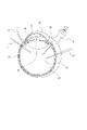
- FIG. 2 schematically shows the cross-sectional structure of the eyeball 30.
- the surface of the eyeball 30 is covered with the cornea 31 and the conjunctiva 32, the iris 34 in which the pupil 33 is formed exists in the back of the cornea 31, and the crystalline lens 35 exists in the back of the iris 34. Further, the retina 36 is present on the entire fundus surface inside the eyeball 30.
- the practitioner 4 inserts the treatment tool 5 into the conjunctiva 32, for example, and performs an operation inside the eyeball 30.
- FIG. 3 schematically shows an example of the configuration of the surgery support device 2.
- the surgery support device 2 includes an endoscope holding device 11, an endoscope 12, an operation unit 13, a calculation / control unit 14, and a monitor 15.
- the endoscope holding device 11 has a base portion 16 and an arm portion 17.
- the base portion 16 is placed on the floor or the like of the operating room, and the arm portion 17 is attached to the base portion 16.
- the arm portion 17 is rotatably supported by the base portion 16.
- the arm portion 17 includes one or more joint portions and rotating portions, and is formed in a mechanism capable of moving the arm tip portion 20 to an arbitrary position.
- FIG. 4 schematically shows an example of the configuration of the arm tip portion 20.
- the arm tip portion 20 has a holder 21 for holding the endoscope 12 and a measuring unit 22 used for measuring the distance of the subject 3 to the cornea 31.
- the holder 21 is formed in a mechanism that allows the endoscope 12 to be attached and detached, and the endoscope 12 is fixed to the holder 21 by attaching the endoscope 12.
- the endoscope 12 can be freely moved to an arbitrary position.
- the practitioner 4 By holding the endoscope 12 inserted into the eyeball 30 of the subject 3 with the holder 21, the practitioner 4 does not need to hold the endoscope 12 by hand. Therefore, the practitioner 4 can perform the operation of the eyeball 30 with both hands.
- the measuring unit 22 has an irradiation unit 23 and an imaging unit 24.
- the irradiation unit 23 is, for example, an LED (Light Emitting Diode), and outputs light that irradiates the eyeball 30 of the subject 3.
- the image pickup unit 24 has image pickup units 24L and 24R so that distance measurement by the so-called stereo method is possible.
- the image pickup units 24L and 24R are arranged at predetermined intervals, for example, in the vicinity of the upper part of the holder 21.
- the optical axes of the image pickup units 24L and 24R are parallel, and the focal lengths are the same.
- the frame periods are synchronized and the frame rates are the same.
- the captured image signals obtained by each of the imaging elements of the imaging units 24L and 24R are A / D (Analog / Digital) converted to be digital image signals (captured image data) representing the luminance value according to a predetermined gradation in pixel units.
- the distance from the image pickup unit 24L, 24R to the cornea 31 of the subject 3 is measured based on the image pickup image signals obtained by each image pickup element of the image pickup unit 24L, 24R obtained in the state where the eyeball 30 is irradiated by the irradiation unit 23. can do.
- the relative positional relationship between the irradiation unit 23 and the imaging units 24L and 24R is fixed. Further, the relative positional relationship between the image pickup units 24L and 24R and the holder 21 described above is fixed. Therefore, by fixing the endoscope 12 to the holder 21, the relative positional relationship between the irradiation unit 23 and the image pickup units 24L and 24R and the endoscope 12 is fixed.
- the endoscope 12 of the surgical support device 2 is inserted into the eyeball 30 in a state of being fixed to the holder 21 (see FIG. 2).
- the state inside the eyeball 30 is imaged by the inserted endoscope 12.
- the captured image signals obtained by the image pickup element of the endoscope 12 are A / D converted, respectively, and are used as digital image signals (captured image data) representing the luminance value according to a predetermined gradation in pixel units.
- the captured image based on the captured image data from the endoscope 12 is displayed on the liquid crystal display of the monitor 15.
- the operation unit 13 comprehensively shows an operation device used for operating the arm unit 17 and rotating an image captured image based on the image captured by the endoscope 12 displayed on the monitor 15.
- the operation unit 13 may be a foot pedal, a remote control device (remote controller) that is manually operated, or the like. Although the foot pedal is shown as an example in FIG. 3, the operation unit 13 is not limited to this as described above. The details of the rotation operation method according to the operation of the operation unit 13 of the captured image by the endoscope 12 will be described later.
- the calculation / control unit 14 performs various processes necessary for realizing the present embodiment, such as operation control of the arm unit 17, generation processing of various images to be displayed on the monitor 15, and display control processing on the monitor 15. Run.
- the calculation / control unit 14 is configured to include, for example, a microcomputer having a CPU (Central Processing Unit), a ROM (Read Only Memory), a RAM (Random Access Memory), and the like.
- the arithmetic / control unit 14 is realized by one or a plurality of microcomputers.
- the calculation / control unit 14 is built in, for example, the base unit 16 of the endoscope holding device 11.
- the arithmetic / control device 14 may be built in another external device.
- the monitor 15 displays the display image 6 on the liquid crystal display based on the display control from the calculation / control unit 14.
- FIG. 5 shows an example of the display image 6 displayed on the monitor 15.
- a display image 6 having an endoscope captured image 61, an eyeball map image 62, an endoscope viewpoint map image 63, an insertion length presentation image 64, and the like is displayed.
- the display image 6 also includes images related to various information as needed.
- the endoscope captured image 61 is an captured image based on the captured image data from the endoscope 12. As the endoscope image captured image 61, for example, the internal state of the eyeball 30 imaged by the endoscope 12 is displayed. The endoscope image 61 can be rotated by an operation by the operation unit 13. The details of the rotation method of the endoscope image 61 will be described later.
- the eyeball map image 62 shows the positional relationship between the eyeball 30 and the endoscope 12.
- the eyeball 30 is displayed by the three-dimensional eyeball model image 30A.
- the position of the endoscope 12 with respect to the eyeball 30 is displayed by the endoscope model image 12A.
- the endoscope viewpoint map image 63 displays an endoscope model image 12B showing the endoscope 12 and a three-dimensional model image 300 of the subject 3 from the viewpoint of the endoscope 12.
- the eyeball model image 30B is displayed on the three-dimensional model image 300.
- the endoscope viewpoint map image 63 rotates in conjunction with the rotation of the endoscope image captured image 61.
- the three-dimensional model image 300 rotates with the position of the endoscope model image 12B showing the endoscope 12 fixed.
- the details of the rotation method of the endoscope viewpoint map image 63 will be described later.
- the insertion length presentation image 64 displays a numerical value of the insertion length of the endoscope 12 with respect to the eyeball 30 and a numerical value of the distance from the endoscope tip portion 120 to the retina 36.
- the practitioner 4 performs an operation on the eyeball 30 while checking the display image 6 displayed on the monitor 15.
- FIG. 6 shows an example of the configuration of the surgery support device 2 as a block diagram.
- the calculation / control unit 14 includes a drive control unit 141, an image processing unit 142, a position determination unit 143, an image generation unit 144, and a display control unit 145.
- the drive control unit 141 controls the operation of the joint portion and the rotating portion of the arm portion 17 of the endoscope holding device 11 based on, for example, an operation signal input from the operation unit 13.
- the drive control unit 141 can move the position of the endoscope 12 fixed to the holder 21 of the arm tip portion 20 by controlling the operation of the arm portion 17. Further, the drive control unit 141 controls the output of the irradiation unit 23 and controls the image pickup of the image pickup unit 24.
- the image processing unit 142 performs various signal processing such as luminance signal processing, color processing, resolution conversion processing, and codec processing on the image signal based on the image captured by the endoscope 12.
- the image processing unit 142 outputs an image signal subjected to various signal processing to the image generation unit 144.
- the position determination unit 143 calculates the image pickup distance, which is the distance from the image pickup unit 24 to the cornea 31, based on the image pickup image signal of the eyeball 30 by each image pickup element of the image pickup units 24L and 24R input from the image pickup unit 24. Further, the position determination unit 143 calculates the relative positional relationship between the eyeball 30 and the endoscope tip portion 120 based on the imaging distance. The position determination unit 143 outputs the determination result (relative positional relationship between the eyeball 30 and the endoscope tip portion 120) to the image generation unit 144.
- the image generation unit 144 generates the display image 6 as shown in FIG. 5 by using various input information from the image processing unit 142, the position determination unit 143, the operation unit 13, and the like. Details of various image generation methods constituting the display image 6 will be described later.
- the image generation unit 144 outputs the image signal of the generated display image 6 to the display control unit 145.
- the display control unit 145 controls to display the display image 6 on the monitor 15 based on the image signal input from the image generation unit 144.
- FIG. 7 is a flowchart showing an example of the processing executed by the calculation / control unit 14.
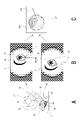
- FIG. 8 shows an outline of a procedure for determining the positional relationship between the eyeball 30 and the endoscope 12.
- step S101 the calculation / control unit 14 performs irradiation start control processing.
- the calculation / control unit 14 causes the irradiation unit 23 to output the light 25 for irradiating the eyeball 30 as shown in FIG. 8A.
- the light 25 output from the irradiation unit 23 is schematically shown by a broken line.
- the irradiation start control process is a process required for determining the positional relationship between the eyeball 30 and the endoscope 12 used for generating the image data of the endoscope viewpoint map image 63 described later.
- step S102 the calculation / control unit 14 stores each frame image data as captured image data obtained by imaging the inside of the eyeball 30 by the endoscope 12 in the internal memory.
- step S103 the calculation / control unit 14 acquires the image rotation angle data.
- the image rotation angle data is information indicating the rotation direction and rotation angle of the captured image data used when performing the rotation processing of the captured image data from the endoscope 12.
- the image rotation angle data is appropriately updated according to the operation input from the operation unit 13. However, the image rotation angle data is not updated when the imaging direction of the endoscope 12 is displaced according to the operation of the arm portion 17.
- the image rotation angle data is the endoscopically captured image. It is a value that indicates the angle of rotation processing of 0 °.
- the calculation / control unit 14 detects an operation input from the operation unit 13, the calculation / control unit 14 updates the image rotation angle data according to the operation amount. For example, the rotation direction is indicated by the positive / negative of the angle of the updated image rotation angle data. The details of the image rotation angle data update process will be described later.
- the calculation / control unit 14 generates the image data of the endoscope image captured image 61 based on the image image data captured from the endoscope 12 and the image rotation angle data. In this case, at least the calculation / control unit 14 generates the image data of the endoscope image captured image 61 in which the image image data captured from the endoscope 12 is rotated in a direction and an angle based on the image rotation angle data.
- the calculation / control unit 14 captures the image captured by the endoscope 12 without rotating it. Image data as an image 61 is generated.
- step S105 the calculation / control unit 14 executes the image generation processing of the eyeball map image 62 and the endoscope viewpoint map image 63.
- This image generation process will be described with reference to FIG.
- FIG. 9 is a flowchart showing an example of the image generation process executed by the calculation / control unit 14.
- step S201 the calculation / control unit 14 stores each frame image data as the captured image data obtained by the imaging units 24L and 24R imaging the eyeball 30 in the internal memory.
- step S202 the calculation / control unit 14 recognizes various images such as recognizing the light spot of the light 25 from the irradiation unit 23 reflected on the eyeball 30 and the cornea 31 of the eyeball 30 based on the two captured image data as each frame. Perform analysis processing.
- step S203 the calculation / control unit 14 shifts the position of the light spot reflected on the cornea 31 with respect to the pair of captured image data (stereo image) obtained by the imaging units 24L and 24R.
- the imaging distance which is the distance from the imaging unit 24 to the cornea 31, is calculated according to the principle of triangulation.
- the calculation / control unit 14 determines the positional relationship between the image pickup unit 24 and the eyeball 30 based on the calculated imaging distance.
- the eyeball model data is used as the data of the size of the eyeball 30.
- the eyeball model data is, for example, three-dimensional data assuming a general human eyeball size. Since the human eyeball size does not differ greatly although there are some individual differences, it is preset as eyeball model data based on the standard human eyeball size.
- the calculation / control unit 14 can calculate (determine) the positional relationship between the image pickup unit 24 and the eyeball 30 by using the image pickup distance and the eyeball model data. It is also possible to measure the eyeball size of the eyeball 30 of the subject 3 in advance for the operation and set the eyeball model data by reflecting the measurement result.
- step S204 the calculation / control unit 14 determines the positional relationship between the endoscope 12 and the eyeball 30 based on the positional relationship between the imaging unit 24 and the eyeball 30.
- the endoscope 12 is fixed to the holder 21 of the arm tip portion 20 so that the relative positional relationship with the imaging unit 24 is fixed. Therefore, in a state where the endoscope 12 is fixed to the holder 21, the position of the endoscope 12 is naturally defined according to the position of the image pickup unit 24. Further, the shape size of the endoscope 12 fixed to the holder 21 up to the endoscope tip portion 120 in the axial direction is known. Therefore, by setting information regarding the shape size of the endoscope 12 in advance, the calculation / control unit 14 can calculate the position of the endoscope tip portion 120 from the specified position of the endoscope 12. can.
- the calculation / control unit 14 can calculate (determine) the positional relationship of the endoscope 12 (endoscope tip portion 120) with respect to the eyeball 30 based on the positional relationship between the eyeball 30 and the imaging unit 24. ..
- the calculation / control unit 14 uses the positional relationship between the determined eyeball 30 and the endoscope 12 (endoscope tip portion 120) as the positional relationship between the three-dimensional eyeball model image 30A and the endoscope model image 12A.
- the image data of the shown eyeball map image 62 is generated (see FIG. 8C).
- step S206 the calculation / control unit 14 generates the image data of the endoscope viewpoint map image 63 as shown in FIG.
- the endoscope viewpoint map image 63 is composed of a three-dimensional model image 300 showing the head of the subject 3 and an endoscope model image 12B showing the endoscope 12.
- the three-dimensional eyeball model image 30B of the eyeball 30 is displayed on the three-dimensional model image 300.
- the value indicating the angle of the head of the subject 3 with respect to the endoscope 12 is the state in which the subject 3 is lying on the operating table 1 on his back, and the endoscope holding device 11 is installed on the operating table 1. It is set in advance as head angle data on the premise that the angle is specified.
- the calculation / control unit 14 generates image data of the three-dimensional model image 300 having the three-dimensional eyeball model image 30B based on the three-dimensional model data and the head angle data.
- the calculation / control unit 14 synthesizes the three-dimensional model image 300 and the endoscope model image 12B based on the positional relationship between the eyeball 30 and the endoscope 12 determined in step S204, so that the endoscope viewpoint map image is obtained.
- Generate 63 image data In the endoscope viewpoint map image 63, an image obtained by observing the head of the three-dimensional model image 300 from the viewpoint of the endoscope 12 is displayed.
- the calculation / control unit 14 generates image data of the endoscope viewpoint map image 63 that has undergone rotation processing based on the image rotation angle data acquired in step S103 of FIG. 7. At this time, the calculation / control unit 14 generates image data obtained by rotating the three-dimensional model image 300 with the position of the endoscope model image 12B fixed as the endoscope viewpoint map image 63.
- the rotation angle of 0 ° is instructed as the image rotation angle data. Therefore, in the calculation / control unit 14, the image data that does not rotate the endoscope viewpoint map image 63 is the endoscope. It is generated as a viewpoint map image 63.
- step S206 the calculation / control unit 14 completes the process of generating the eyeball map image 62 and the endoscope viewpoint map image 63 in S105 of FIG. 7. Subsequently, the calculation / control unit 14 proceeds to the process in step S106.
- step S106 the calculation / control unit 14 generates the image data of the display image 6.
- the calculation / control unit 14 generates a display image 6 by synthesizing an endoscope image captured image 61, an eyeball map image 62, an endoscope viewpoint map image 63, an insertion length presentation image 64, and other necessary images.
- the calculation / control unit 14 obtains information on the insertion length of the endoscope 12 into the eyeball 30 and the endoscope tip portion 120 based on the positional relationship between the determined eyeball 30 and the endoscope 12 (endoscope tip portion 120). And the information about the distance from the subject 3 to the retina 36 is calculated. Then, the calculation / control unit 14 generates the image data of the insertion length presentation image 64 based on the information.
- step S107 the calculation / control unit 14 performs display control for displaying the display image 6 on the liquid crystal display of the monitor 15. As a result, the display image 6 as shown in FIG. 5 is displayed on the same screen of the monitor 15.
- the treatment tool 5 may be reflected in the endoscope image captured image 61 as shown in FIG.
- the endoscopic image 61 does not match the direction in which the practitioner 4 shown in FIG. 1 performs the operation inside the eyeball 30 in the vertical and horizontal directions.
- the practitioner 4 needs to rotate the endoscope image 61 to a position where it is easy to see (for example, the position shown in FIG. 11) by operating the operation unit 13 in order to smoothly proceed the operation. Therefore, the calculation / control unit 14 performs the processes of steps S108 and S109 in FIG.
- step S108 the calculation / control unit 14 determines whether or not an operation input from the operation unit 13 has been detected.
- the operation input is performed, for example, by the practitioner 4 operating the foot pedal with his / her foot.
- step S108 the calculation / control unit 14 returns the process to step S102, and then executes the same process. That is, in the initial state, the endoscope image captured image 61 and the endoscope viewpoint map image 63 in a non-rotating state are displayed on the monitor 15.
- step S108 when the operation input is detected in step S108, the calculation / control unit 14 proceeds from step S108 to S109.
- step S109 the calculation / control unit 14 updates the image rotation angle data.
- the calculation / control unit 14 updates the rotation direction and the rotation angle as image rotation angle data based on the operation input from the operation unit 13.
- step S109 the calculation / control unit 14 returns the processing to step S102. Then, the calculation / control unit 14 performs the processes of steps S102 to S104, and rotates the image data captured by the endoscope 12 based on the updated image rotation angle data to obtain the image data of the endoscope image 61. Generate.
- the endoscope imaging displayed on the monitor 15 is performed according to the operation of the operation unit 13 without causing the positional displacement of the endoscope 12 inside the eyeball 30.
- the image 61 can continue to rotate.
- the endoscope image 61 can be rotated from the position shown in FIG. 10 to the position shown in FIG.
- the calculation / control unit 14 fixes the position of the endoscope model image 12B and makes a three-dimensional model based on the updated image rotation angle data.
- the image data of the endoscope viewpoint map image 63 in which the image 300 is rotated is generated.
- the three-dimensional model image 300 rotates with reference to the fixed endoscope model image 12B.
- the three-dimensional model image 300 is moved from the position shown in FIG. 10 with respect to the endoscope model image 12B. Rotate to the position shown in FIG.
- the image data of the endoscope viewpoint map image 63 rotated in conjunction with the rotation of the endoscope image captured image 61 is generated. Can be done.
- step S106 the calculation / control unit 14 generates image data of the display image 6 including the rotated endoscope image captured image 61 and the endoscope viewpoint map image 63.
- step S107 the calculation / control unit 14 performs display control for displaying the display image 6 on the liquid crystal display of the monitor 15.
- the endoscope image captured image 61 rotated according to the operation of the operation unit 13 of the practitioner 4 is displayed on the monitor 15. Further, the endoscope viewpoint map image 63 rotated in conjunction with the rotation of the endoscope captured image 61 is displayed on the monitor 15.
- the positional relationship between the eyeball 30 and the endoscope 12 (for example, the insertion state of the endoscope 12 with respect to the eyeball 30 (imaging direction)) is spatially determined from the image of the endoscope image 61. It may be difficult to grasp. In such a case, by checking the endoscope viewpoint map image 63 that is rotated in conjunction with the rotation of the endoscope image captured image 61, it is possible to easily grasp the insertion state of the endoscope 12 with respect to the eyeball 30. can.
- the processes from steps S102 to S109 are continuously executed by the calculation / control unit 14.
- the practitioner 4 continues the operation of the operation unit 13 until, for example, the treatment tool 5 reflected in the endoscope image 61 is in a position where surgery can be easily performed, and rotates the endoscope image 61.
- the calculation / control unit 14 determines that the operation input is not detected in step S108. In this case, the calculation / control unit 14 returns the process from step S108 to S102, and then repeatedly executes the process from step S102 to S108 until the operation input is detected in step S108.
- the calculation / control unit 14 generates image data of the endoscope image captured image 61 and the endoscope viewpoint map image 63 based on the last updated image rotation angle data, and controls the display on the monitor 15. ..
- the endoscope image captured image 61 and the endoscope viewpoint map image 63 are displayed on the monitor 15 in a state where the rotation angle at the time of stopping the rotation is maintained.
- the image rotation angle data is updated by the calculation / control unit 14. Will not be done.
- the endoscope-captured image 61 in which only the imaging direction is displaced is displayed on the monitor 15 in a state where the rotation based on the last updated image rotation angle data is maintained. Therefore, the practitioner 4 does not need to rotate the endoscope image captured image 61 again by the operation of the operation unit 13 when the image pickup direction of the endoscope 12 is displaced.
- the endoscope viewpoint map image 63 the state linked to the rotational state of the endoscope image captured image 61 is maintained.
- the imaging direction of the endoscope 12 is displaced, the position of the three-dimensional model image 300 with respect to the endoscope model image 12B in the endoscope viewpoint map image 63 is displaced.
- step S108 When the operation input is detected again in step S108 while the processes of steps S102 to S108 are repeatedly executed, the calculation / control unit 14 proceeds with the processes in the order of steps S109 and S102, and then executes the same process.
- the surgical support device 2 has a holder 21 for holding the endoscope 12, and an arm for adjusting the position of the endoscope 12 while the endoscope 12 is held by the holder 21.
- the image generation unit 144 that generates the endoscope viewpoint map image 63 on which the three-dimensional model image 300 of the subject 3 from the viewpoint of the endoscope 12 held in the holder 21 is displayed, and the endoscope.
- a display control unit 145 that controls the display of the viewpoint map image 63 and the endoscope image captured image 61 captured by the endoscope 12 and an operation unit 13 for rotating the endoscope image captured image 61 are provided and operated.
- the endoscope image captured image 61 displayed without causing the positional displacement of the endoscope 12 is rotated, and the endoscope viewpoint map image 63 is rotated in conjunction with the rotation. (See FIGS. 7 and 8).
- the endoscope viewpoint map image 63 showing the positional relationship between the endoscope 12 and the subject 3 corresponding to the state of the endoscope image captured image 61 after rotation is displayed. Therefore, the practitioner 4 can spatially grasp the insertion state of the endoscope 12 with respect to the eyeball 30 of the subject 3. Therefore, the practitioner 4 can perform an operation in which the positional relationship is intuitively grasped even in a state where the endoscope image 61 is rotated, and the operation on the eyeball 30 can proceed smoothly. Further, since the position of the endoscope 12 can be grasped, it is possible to prevent the practitioner 4 from coming into contact with the endoscope 12 or the like.
- the rotation of the endoscope viewpoint map image 63 is performed in a state where the position of the image showing the endoscope 12 is fixed (S105 in FIG. 7, S205 in FIG. 9, See FIGS. 10, 11 and the like).
- the endoscope viewpoint map image 63 is always displayed in a state where the image showing the endoscope 12 is reflected regardless of the rotational state of the endoscope image captured image 61. Therefore, by visually recognizing the endoscope viewpoint map image 63, it is possible to always confirm the insertion state of the endoscope 12 into the eyeball 30 of the subject 3 regardless of the rotation of the endoscope image captured image 61. Therefore, the surgery on the eyeball 30 can proceed smoothly.
- the display control unit 145 displays the endoscope viewpoint map image 63 and the endoscope image captured image 61 on the same screen (see S107 and the like in FIGS. 5 and 7). ..
- the endoscope viewpoint map image 63 can be confirmed without shifting the line of sight to another monitor 15. Therefore, the visibility of the endoscope viewpoint map image 63 is improved, and the operation on the eyeball 30 can proceed smoothly.
- the display control unit 145 displays the eyeball map image 62 showing the position of the endoscope 12 on the three-dimensional eyeball model and the endoscope viewpoint map image 63 on the same screen. Display (see S107 and the like in FIGS. 5 and 7).
- the eyeball map image 62 can be confirmed without shifting the line of sight to another monitor 15. Therefore, since a plurality of information can be confirmed simultaneously on one monitor 15, the operation on the eyeball 30 can proceed smoothly.
- the example of the endoscope is described as an example of the endoscope 12, but the endoscope 12 is not limited to the endoscope.
- various endoscopes can be applied, such as a thoracoscope incising and inserting between the ribs of the subject 3 and a laparoscope incising and inserting the abdomen.
- the embodiments described in the present disclosure are merely examples, and the present invention is not limited to the above-described embodiments. Moreover, not all of the combinations of configurations described in the embodiments are essential for solving the problem. Further, the effects described in the present disclosure are merely exemplary and not limited, and may have other effects, or may play a part of the effects described in the present disclosure. good.
Landscapes
- Health & Medical Sciences (AREA)
- Life Sciences & Earth Sciences (AREA)
- Surgery (AREA)
- Engineering & Computer Science (AREA)
- Veterinary Medicine (AREA)
- Public Health (AREA)
- General Health & Medical Sciences (AREA)
- Animal Behavior & Ethology (AREA)
- Biomedical Technology (AREA)
- Heart & Thoracic Surgery (AREA)
- Physics & Mathematics (AREA)
- Nuclear Medicine, Radiotherapy & Molecular Imaging (AREA)
- Medical Informatics (AREA)
- Molecular Biology (AREA)
- Pathology (AREA)
- Biophysics (AREA)
- Radiology & Medical Imaging (AREA)
- Optics & Photonics (AREA)
- Ophthalmology & Optometry (AREA)
- Signal Processing (AREA)
- General Physics & Mathematics (AREA)
- Theoretical Computer Science (AREA)
- Oral & Maxillofacial Surgery (AREA)
- Vascular Medicine (AREA)
- Endoscopes (AREA)
- Eye Examination Apparatus (AREA)
- Image Processing (AREA)
Abstract
被術者に対する内視鏡の挿入状態を空間的に把握できるような表示を行うために、内視鏡を保持するためのホルダを有し、前記ホルダで前記内視鏡を保持した状態で前記内視鏡の位置を調節するアーム部と、前記ホルダに保持された前記内視鏡の視点による被術者の三次元モデルの画像である内視鏡視点マップ画像を生成する画像生成部と、前記内視鏡視点マップ画像と前記内視鏡により撮像した内視鏡撮像画像との表示制御を行う表示制御部と、前記内視鏡撮像画像を回転させるための操作部と、を備え、前記操作部の操作に応じて、前記内視鏡の位置変位を生じさせずに表示されている前記内視鏡撮像画像を回転させるとともに、該回転に連動して前記内視鏡視点マップ画像を回転させる。
Description
本発明は、内視鏡を保持する機能を備える手術支援装置の技術分野に関する。
例えば黄班症や網膜剥離等の治療のために、眼球内部の硝子体を吸引除去することにより網膜を正常な状態に戻す硝子体手術が知られている。
通常の硝子体手術において、施術者(医師)は、手術顕微鏡等により被術者(患者)の瞳孔を通じて眼球内部を観察することになるが、瞳孔を通じて観察できる眼球内部の範囲には限界があり、観察できない部分を可視範囲に入れるためには眼球を外側から圧迫する必要がある。このような圧迫は、手術中の疼痛や手術後の炎症を引き起こすおそれがある。
通常の硝子体手術において、施術者(医師)は、手術顕微鏡等により被術者(患者)の瞳孔を通じて眼球内部を観察することになるが、瞳孔を通じて観察できる眼球内部の範囲には限界があり、観察できない部分を可視範囲に入れるためには眼球を外側から圧迫する必要がある。このような圧迫は、手術中の疼痛や手術後の炎症を引き起こすおそれがある。
そこで、特許文献1に示すような硝子体手術に内視鏡を用いる手法が提案されている。
内視鏡を被術者の眼球内部に挿入することで、眼球内部の画像がモニタ等の表示手段に表示される。施術者は、眼球内部で内視鏡を移動させることで、通常瞳孔からは視認できない部分を容易に観察することができる。
このような内視鏡を用いた硝子体手術においては、眼球内部の観察にあたり眼球を圧迫する必要がなくなるため、被術者の眼球に対する負担を軽減することができる。
内視鏡を被術者の眼球内部に挿入することで、眼球内部の画像がモニタ等の表示手段に表示される。施術者は、眼球内部で内視鏡を移動させることで、通常瞳孔からは視認できない部分を容易に観察することができる。
このような内視鏡を用いた硝子体手術においては、眼球内部の観察にあたり眼球を圧迫する必要がなくなるため、被術者の眼球に対する負担を軽減することができる。
硝子体手術では、硝子体カッターや鉗子、灌流液等の注入器などの処置具を眼球に挿入することで手術が行われる。施術者は内視鏡による撮像に基づく内視鏡撮像画像をモニタ上で確認しながら眼球内部の手術を行う。
このような内視鏡を用いた手術において、施術者が、被術者の眼球に対する内視鏡の挿入状態を推測し、モニタ上に表示された内視鏡撮像画像が眼球内部のどの位置を映し出したものであるかを把握することは容易ではない。
そこで本発明では、被術者に対する内視鏡の挿入状態を空間的に把握できるような表示を行うことを目的とする。
このような内視鏡を用いた手術において、施術者が、被術者の眼球に対する内視鏡の挿入状態を推測し、モニタ上に表示された内視鏡撮像画像が眼球内部のどの位置を映し出したものであるかを把握することは容易ではない。
そこで本発明では、被術者に対する内視鏡の挿入状態を空間的に把握できるような表示を行うことを目的とする。
本発明に係る手術支援装置は、内視鏡を保持するためのホルダを有し、前記ホルダで前記内視鏡を保持した状態で前記内視鏡の位置を調節するアーム部と、前記ホルダに保持された前記内視鏡の視点による被術者の三次元モデルの画像である内視鏡視点マップ画像を生成する画像生成部と、前記内視鏡視点マップ画像と前記内視鏡により撮像した内視鏡撮像画像との表示制御を行う表示制御部と、前記内視鏡撮像画像を回転させるための操作部と、を備え、前記操作部の操作に応じて、前記内視鏡の位置変位を生じさせずに表示されている前記内視鏡撮像画像を回転させるとともに、該回転に連動して前記内視鏡視点マップ画像を回転させるものである。
これにより回転後の内視鏡撮像画像の状態に対応する内視鏡と被術者の位置関係を示す内視鏡視点マップ画像が表示される。
これにより回転後の内視鏡撮像画像の状態に対応する内視鏡と被術者の位置関係を示す内視鏡視点マップ画像が表示される。
上記した手術支援装置において、前記内視鏡視点マップ画像の回転は、前記内視鏡を示す画像の位置を固定した状態で行われることが考えられる。
これにより、内視鏡撮像画像の回転状態を問わず、必ず内視鏡を示す画像が映り込んだ状態で内視鏡視点マップ画像が表示される。
これにより、内視鏡撮像画像の回転状態を問わず、必ず内視鏡を示す画像が映り込んだ状態で内視鏡視点マップ画像が表示される。
上記した手術支援装置において、前記表示制御部は、前記内視鏡視点マップ画像と前記内視鏡撮像画像とを同一画面内に表示させることが考えられる。
これにより、内視鏡撮像画像を視認しながら手術を行うにあたり、他のモニタに視線を移すことなく内視鏡視点マップ画像を確認することができる。
これにより、内視鏡撮像画像を視認しながら手術を行うにあたり、他のモニタに視線を移すことなく内視鏡視点マップ画像を確認することができる。
上記した手術支援装置において、表示制御部は、三次元眼球モデル上で前記内視鏡の位置を示す眼球マップ画像と、前記内視鏡視点マップ画像とを同一画面内に表示させることが考えられる。
これにより、内視鏡視点マップ画像を視認しているときに、他のモニタに視線を移すことなく眼球マップ画像を確認することができる。
これにより、内視鏡視点マップ画像を視認しているときに、他のモニタに視線を移すことなく眼球マップ画像を確認することができる。
本発明によれば、被術者に対する内視鏡の挿入状態を空間的に把握することができる。
本発明の実施の形態について図1から図11を参照して説明する。図面は、説明にあたり必要と認められる要部及びその周辺の構成を抽出して示している。また図面は模式的なものであり、図面に記載された各構造の寸法、比率等は一例に過ぎない。従って、本発明の技術的思想を逸脱しない範囲であれば設計などに応じて種々な変更が可能である。また一度説明した構成は、以降同一の符号を付して説明を省略することがある。
以下、実施の形態を次の順序で説明する。
<1.手術システムの構成>
<2.演算・制御部の機能構成>
<3.実施の形態の処理例>
<4.まとめ>
<1.手術システムの構成>
<2.演算・制御部の機能構成>
<3.実施の形態の処理例>
<4.まとめ>
<1.手術システムの構成>
眼球手術における手術システム100の構成について説明する。
図1は手術システム100が有する構成の一例を模式的に示している。
手術システム100は、手術台1と手術支援装置2を有して構成される。
手術台1と手術支援装置2は手術室に設置されている。
眼球手術における手術システム100の構成について説明する。
図1は手術システム100が有する構成の一例を模式的に示している。
手術システム100は、手術台1と手術支援装置2を有して構成される。
手術台1と手術支援装置2は手術室に設置されている。
手術台1には、被術者(患者)3が仰向けの状態で横たえられている。施術者(医師)4は、被術者3の頭部側に位置し、各種の処置具5を用いて被術者3の眼球30(図2参照)内部の手術を行う。処置具5には、例えば硝子体カッターや鉗子、灌流液等の注入器などが用いられる。
図2は、眼球30の断面構成を模式的に示している。眼球30の表面は角膜31及び結膜32により覆われており、角膜31の奥には瞳孔33が形成された虹彩34が存在し、虹彩34の奥には水晶体35が存在する。また眼球30内部の眼底一面には網膜36が存在する。
施術者4は、例えば結膜32に処置具5を挿入して眼球30内部の手術を行う。
施術者4は、例えば結膜32に処置具5を挿入して眼球30内部の手術を行う。
施術者4による眼球30の手術は、手術支援装置2により支援される。
図3は、手術支援装置2が有する構成の一例を模式的に示している。
手術支援装置2は、内視鏡保持装置11、内視鏡12、操作部13、演算・制御部14、及びモニタ15を有する。
図3は、手術支援装置2が有する構成の一例を模式的に示している。
手術支援装置2は、内視鏡保持装置11、内視鏡12、操作部13、演算・制御部14、及びモニタ15を有する。
内視鏡保持装置11は、基台部16及びアーム部17を有している。
基台部16は手術室の床等に載置され、アーム部17は基台部16に取り付けられている。アーム部17は基台部16により回動可能に軸支される。
アーム部17は、1又は複数の関節部や回動部を備え、アーム先端部20を任意の位置に移動させることのできる機構に形成されている。
基台部16は手術室の床等に載置され、アーム部17は基台部16に取り付けられている。アーム部17は基台部16により回動可能に軸支される。
アーム部17は、1又は複数の関節部や回動部を備え、アーム先端部20を任意の位置に移動させることのできる機構に形成されている。
ここでアーム先端部20の構成について説明する。
図4は、アーム先端部20が有する構成の一例を模式的に示している。
アーム先端部20は、内視鏡12を保持するためのホルダ21と被術者3の角膜31までの距離の計測に用いる計測部22と、を有している。
図4は、アーム先端部20が有する構成の一例を模式的に示している。
アーム先端部20は、内視鏡12を保持するためのホルダ21と被術者3の角膜31までの距離の計測に用いる計測部22と、を有している。
ホルダ21は、内視鏡12が着脱可能となる機構に形成され、内視鏡12を装着することでホルダ21に対して内視鏡12が固定される。内視鏡12がホルダ21に固定された状態でアーム部17を動作させることで、内視鏡12を任意の位置に自在に移動させることができる。
被術者3の眼球30に挿入された内視鏡12をホルダ21で保持することで、施術者4は、手で内視鏡12を保持する必要がなくなる。従って、施術者4は、両手で眼球30の手術を行うことができる。
計測部22は、照射部23及び撮像部24を有している。
照射部23は、例えばLED(Light Emitting Diode)であり、被術者3の眼球30を照射する光を出力する。
照射部23は、例えばLED(Light Emitting Diode)であり、被術者3の眼球30を照射する光を出力する。
撮像部24は、いわゆるステレオ法による測距が可能となるように撮像部24L,24Rを有している。撮像部24L,24Rは、例えばホルダ21の上部付近において所定間隔を空けて配置されている。撮像部24L,24Rの光軸は平行とされ、焦点距離はそれぞれ同値とされる。また、フレーム周期は同期し、フレームレートも一致している。
撮像部24L,24Rの各撮像素子で得られた撮像画像信号はそれぞれA/D(Analog / Digital)変換され、画素単位で所定階調による輝度値を表すデジタル画像信号(撮像画像データ)とされる。
照射部23により眼球30が照射された状態において得られた撮像部24L,24Rの各撮像素子による撮像画像信号に基づいて、撮像部24L,24Rから被術者3の角膜31までの距離を計測することができる。
計測部22において照射部23と撮像部24L,24Rの相対位置関係は固定されている。また撮像部24L,24Rと、上述したホルダ21の相対位置関係は固定されている。従って、ホルダ21に内視鏡12を固定することで、照射部23及び撮像部24L,24Rと内視鏡12との相対位置関係が固定される。
図3に戻り、手術支援装置2の内視鏡12は、ホルダ21に固定された状態で眼球30の内部に挿入される(図2参照)。挿入された内視鏡12により眼球30内部の状態が撮像される。内視鏡12の撮像素子で得られた撮像画像信号はそれぞれA/D変換され、画素単位で所定階調による輝度値を表すデジタル画像信号(撮像画像データ)とされる。
内視鏡12からの撮像画像データに基づく撮像画像は、モニタ15の液晶に表示される。
内視鏡12からの撮像画像データに基づく撮像画像は、モニタ15の液晶に表示される。
操作部13は、アーム部17の操作やモニタ15上で表示された内視鏡12による撮像に基づく撮像画像の回転操作などを行う際に用いられる操作機器を包括的に示している。操作部13は、フットペダルであってもよいし、手動により操作する遠隔操作装置(リモートコントローラ)などであってもよい。図3では一例としてフットペダルを図示しているが、上記の通り操作部13はこれに限れられるものではない。
内視鏡12による撮像画像の操作部13の操作に応じた回転操作手法の詳細については後述する。
内視鏡12による撮像画像の操作部13の操作に応じた回転操作手法の詳細については後述する。
演算・制御部14は、アーム部17の動作制御や、モニタ15上に表示させる各種画像の生成処理、モニタ15への表示制御処理など、本実施の形態を実現するために必要な各種処理を実行する。
演算・制御部14は、例えばCPU(Central Processing Unit)、ROM(Read Only Memory)、RAM(Random Access Memory)等を有するマイクロコンピュータを備えて構成される。演算・制御部14は、1又は複数のマイクロコンピュータにより実現される。
演算・制御部14は、例えば内視鏡保持装置11の基台部16に内蔵されている。なお、演算・制御装置14は他の外部機器に内蔵されていてもよい。
モニタ15は、演算・制御部14からの表示制御に基づいて液晶に表示画像6を表示する。
図5は、モニタ15上に表示される表示画像6の一例を示している。
モニタ15上には、例えば内視鏡撮像画像61や、眼球マップ画像62、内視鏡視点マップ画像63、挿入長提示画像64などを有する表示画像6が表示される。表示画像6には他にも必要に応じて各種情報に関する画像が含まれる。
図5は、モニタ15上に表示される表示画像6の一例を示している。
モニタ15上には、例えば内視鏡撮像画像61や、眼球マップ画像62、内視鏡視点マップ画像63、挿入長提示画像64などを有する表示画像6が表示される。表示画像6には他にも必要に応じて各種情報に関する画像が含まれる。
内視鏡撮像画像61は、内視鏡12からの撮像画像データに基づく撮像画像である。内視鏡撮像画像61として、例えば内視鏡12で撮像した眼球30の内部の状態が表示される。内視鏡撮像画像61は、操作部13による操作により回転させることができる。内視鏡撮像画像61の回転手法の詳細については後述する。
眼球マップ画像62は眼球30と内視鏡12の位置関係を示している。
眼球マップ画像62には、眼球30が三次元眼球モデル画像30Aにより表示される。また眼球30に対する内視鏡12の位置が内視鏡モデル画像12Aにより表示される。
眼球マップ画像62には、眼球30が三次元眼球モデル画像30Aにより表示される。また眼球30に対する内視鏡12の位置が内視鏡モデル画像12Aにより表示される。
内視鏡視点マップ画像63には、内視鏡12を示す内視鏡モデル画像12Bと、内視鏡12の視点による被術者3の三次元モデル画像300とが表示される。三次元モデル画像300には眼球モデル画像30Bが表示される。
内視鏡視点マップ画像63は、内視鏡撮像画像61の回転に連動して回転する。このとき内視鏡視点マップ画像63においては、内視鏡12を示す内視鏡モデル画像12Bの位置を固定した状態で、三次元モデル画像300が回転する。内視鏡視点マップ画像63の回転手法の詳細については後述する。
内視鏡視点マップ画像63は、内視鏡撮像画像61の回転に連動して回転する。このとき内視鏡視点マップ画像63においては、内視鏡12を示す内視鏡モデル画像12Bの位置を固定した状態で、三次元モデル画像300が回転する。内視鏡視点マップ画像63の回転手法の詳細については後述する。
挿入長提示画像64には、眼球30に対する内視鏡12の挿入長の数値、及び内視鏡先端部120から網膜36までの距離の数値が表示される。
施術者4は、モニタ15上で表示された表示画像6を確認しながら眼球30の手術を行う。
<2.演算・制御部の機能構成>
手術支援装置2における演算・制御部14の機能構成について説明する。
図6は、手術支援装置2の構成の一例をブロック図として示している。
演算・制御部14は、駆動制御部141、画像処理部142、位置判定部143、画像生成部144、及び表示制御部145を有している。
手術支援装置2における演算・制御部14の機能構成について説明する。
図6は、手術支援装置2の構成の一例をブロック図として示している。
演算・制御部14は、駆動制御部141、画像処理部142、位置判定部143、画像生成部144、及び表示制御部145を有している。
駆動制御部141は、例えば操作部13からの入力された操作信号に基づいて、内視鏡保持装置11のアーム部17の関節部や回動部の動作制御を行う。駆動制御部141は、アーム部17の動作制御を行うことで、アーム先端部20のホルダ21に固定した内視鏡12の位置を移動させることができる。
また駆動制御部141は、照射部23の出力制御や、撮像部24の撮像制御を行う。
また駆動制御部141は、照射部23の出力制御や、撮像部24の撮像制御を行う。
画像処理部142は、内視鏡12による撮像に基づく画像信号について、輝度信号処理、色処理、解像度変換処理、コーデック処理などの各種信号処理を施す。画像処理部142は、各種信号処理が施された画像信号を画像生成部144に出力する。
位置判定部143は、撮像部24から入力された撮像部24L,24Rの各撮像素子による眼球30の撮像画像信号に基づいて、撮像部24から角膜31までの距離である撮像距離を演算する。
また位置判定部143は、当該撮像距離に基づいて眼球30と内視鏡先端部120との相対位置関係を演算する。
位置判定部143は、判定結果(眼球30と内視鏡先端部120との相対位置関係)を画像生成部144に出力する。
また位置判定部143は、当該撮像距離に基づいて眼球30と内視鏡先端部120との相対位置関係を演算する。
位置判定部143は、判定結果(眼球30と内視鏡先端部120との相対位置関係)を画像生成部144に出力する。
画像生成部144は、画像処理部142や位置判定部143、操作部13などからの各種入力情報を用いて図5に示すような表示画像6を生成する。表示画像6を構成する各種画像の生成手法の詳細については後述する。
画像生成部144は、生成した表示画像6の画像信号を表示制御部145に出力する。
画像生成部144は、生成した表示画像6の画像信号を表示制御部145に出力する。
表示制御部145は、画像生成部144から入力された画像信号に基づいて、モニタ15上に表示画像6を表示させる制御を行う。
<3.実施の形態の処理例>
本実施の形態を実現するために手術支援装置2の演算・制御部14が実行する処理について説明する。ここでは一例として、施術者4が被術者3の頭部側に位置して手術を行っているものとする(図1参照)。
図7は、演算・制御部14が実行する処理の一例を示すフローチャートである。また図8は、眼球30と内視鏡12の位置関係を判定するための手順の概要を示している。
本実施の形態を実現するために手術支援装置2の演算・制御部14が実行する処理について説明する。ここでは一例として、施術者4が被術者3の頭部側に位置して手術を行っているものとする(図1参照)。
図7は、演算・制御部14が実行する処理の一例を示すフローチャートである。また図8は、眼球30と内視鏡12の位置関係を判定するための手順の概要を示している。
ステップS101において、演算・制御部14は照射開始制御処理を行う。
照射開始制御処理において、演算・制御部14は、図8Aに示すように眼球30を照射するための光25を照射部23に出力させる。なお、図8Aでは照射部23から出力される光25を模式的に破線で示している。
照射開始制御処理は、後述する内視鏡視点マップ画像63の画像データを生成するために用いられる眼球30と内視鏡12の位置関係を判定する際に必要となる処理である。
照射開始制御処理において、演算・制御部14は、図8Aに示すように眼球30を照射するための光25を照射部23に出力させる。なお、図8Aでは照射部23から出力される光25を模式的に破線で示している。
照射開始制御処理は、後述する内視鏡視点マップ画像63の画像データを生成するために用いられる眼球30と内視鏡12の位置関係を判定する際に必要となる処理である。
その後、演算・制御部14は、画像の1フレームタイミング毎にステップS102以降の処理を繰り返し実行する。
ステップS102において、演算・制御部14は、内視鏡12が眼球30内部を撮像して得た撮像画像データとしての各フレーム画像データを内部メモリに格納する。
ステップS102において、演算・制御部14は、内視鏡12が眼球30内部を撮像して得た撮像画像データとしての各フレーム画像データを内部メモリに格納する。
ステップS103において、演算・制御部14は画像回転角データを取得する。
画像回転角データは、内視鏡12からの撮像画像データの回転処理を行う際に用いられる当該撮像画像データの回転方向及び回転角度を示す情報である。
画像回転角データは、操作部13からの操作入力に応じて適宜更新される。ただし、アーム部17の動作に応じて内視鏡12の撮像方向が変位することによっては、画像回転角データは更新されない。
画像回転角データは、内視鏡12からの撮像画像データの回転処理を行う際に用いられる当該撮像画像データの回転方向及び回転角度を示す情報である。
画像回転角データは、操作部13からの操作入力に応じて適宜更新される。ただし、アーム部17の動作に応じて内視鏡12の撮像方向が変位することによっては、画像回転角データは更新されない。
演算・制御部14が図7の処理を開始してから操作部13による操作入力を検知するまでの間(以下、初期状態とも表記する。)においては、画像回転角データは内視鏡撮像画像に対する回転処理の角度0°を指示する値とされる。
演算・制御部14は、操作部13からの操作入力を検知すると、その操作量に応じて画像回転角データを更新する。例えば更新された画像回転角データの角度の正負により回転方向が示される。画像回転角データの更新処理の詳細については後述する。
演算・制御部14は、操作部13からの操作入力を検知すると、その操作量に応じて画像回転角データを更新する。例えば更新された画像回転角データの角度の正負により回転方向が示される。画像回転角データの更新処理の詳細については後述する。
続くステップS104において、演算・制御部14は、内視鏡12からの撮像画像データ及び画像回転角データに基づいて、内視鏡撮像画像61の画像データを生成する。
この場合少なくとも演算・制御部14は、内視鏡12からの撮像画像データを画像回転角データに基づいた方向及び角度で回転させた内視鏡撮像画像61の画像データを生成する。
この場合少なくとも演算・制御部14は、内視鏡12からの撮像画像データを画像回転角データに基づいた方向及び角度で回転させた内視鏡撮像画像61の画像データを生成する。
また初期状態の場合は画像回転角データとして回転角度0°が指示されていることになるため、演算・制御部14は、内視鏡12からの撮像画像データを回転させずに内視鏡撮像画像61としての画像データを生成する。
ステップS105において、演算・制御部14は、眼球マップ画像62及び内視鏡視点マップ画像63の画像生成処理を実行する。この画像生成処理について図9を参照して説明する。図9は、演算・制御部14が実行する当該画像生成処理の一例を示すフローチャートである。
ステップS201において、演算・制御部14は、撮像部24L,24Rが眼球30を撮像することで得た撮像画像データとしての各フレーム画像データを内部メモリに格納する。
ステップS202において、演算・制御部14は、各フレームとしての2つの撮像画像データに基づき、眼球30や眼球30の角膜31に映る照射部23からの光25の光点を認識するなどの各種画像解析処理を行う。
ステップS203において、演算・制御部14は、撮像部24L,24Rにより得られた一対の撮像画像データ(ステレオ画像)に対し、図8Bに示すような角膜31に映る光点の位置のずれ量Lから三角測量の原理によって撮像部24から角膜31までの距離である撮像距離を演算する。
演算・制御部14は、演算した撮像距離に基づいて撮像部24と眼球30の位置関係を判定する。
このとき眼球30のサイズのデータとして眼球モデルデータが用いられる。
眼球モデルデータは、例えば一般的なヒトの眼球サイズを想定した三次元データである。ヒトの眼球サイズは、若干の個人差はあるものの大きく異なることがないため、標準的なヒトの眼球サイズに基づく眼球モデルデータとしてあらかじめ設定しておく。
このとき眼球30のサイズのデータとして眼球モデルデータが用いられる。
眼球モデルデータは、例えば一般的なヒトの眼球サイズを想定した三次元データである。ヒトの眼球サイズは、若干の個人差はあるものの大きく異なることがないため、標準的なヒトの眼球サイズに基づく眼球モデルデータとしてあらかじめ設定しておく。
演算・制御部14は、撮像距離と眼球モデルデータを用いることで、撮像部24と眼球30の位置関係を演算(判定)することができる。
なお、手術にあたりあらかじめ被術者3の眼球30の眼球サイズを測定しておき、当該測定結果を反映させて眼球モデルデータを設定することもできる。
なお、手術にあたりあらかじめ被術者3の眼球30の眼球サイズを測定しておき、当該測定結果を反映させて眼球モデルデータを設定することもできる。
続くステップS204において、演算・制御部14は、撮像部24と眼球30の位置関係に基づいて、内視鏡12と眼球30の位置関係を判定する。
内視鏡12は、アーム先端部20のホルダ21に固定されることで撮像部24との相対位置関係が固定される。そのため内視鏡12がホルダ21に固定された状態では、撮像部24の位置に応じておのずと内視鏡12の位置が規定される。
またホルダ21に固定された内視鏡12の軸方向における内視鏡先端部120までの形状サイズは既知である。そのため、内視鏡12の形状サイズに関する情報をあらかじめ設定しておくことで、演算・制御部14は、規定された内視鏡12の位置から内視鏡先端部120の位置を演算することができる。
またホルダ21に固定された内視鏡12の軸方向における内視鏡先端部120までの形状サイズは既知である。そのため、内視鏡12の形状サイズに関する情報をあらかじめ設定しておくことで、演算・制御部14は、規定された内視鏡12の位置から内視鏡先端部120の位置を演算することができる。
以上により、演算・制御部14は、眼球30と撮像部24の位置関係に基づいて、眼球30に対する内視鏡12(内視鏡先端部120)の位置関係を演算(判定)することができる。
続くステップS205において、演算・制御部14は、判定した眼球30と内視鏡12(内視鏡先端部120)の位置関係を三次元眼球モデル画像30Aと内視鏡モデル画像12Aの位置関係として示した眼球マップ画像62の画像データを生成する(図8C参照)。
さらにステップS206において、演算・制御部14は、図5に示すような内視鏡視点マップ画像63の画像データを生成する。内視鏡視点マップ画像63は、被術者3の頭部を示す三次元モデル画像300と、内視鏡12を示す内視鏡モデル画像12Bとから構成される。三次元モデル画像300には眼球30の三次元眼球モデル画像30Bが表示される。
被術者3の三次元モデル画像300には、あらかじめ設定されたヒトの三次元モデルデータが用いられる。
また内視鏡12に対する被術者3の頭部の角度を示す値が、被術者3が手術台1に仰向けで横たえられた状態であり、手術台1に対する内視鏡保持装置11の設置角度が規定されているという前提のもと、あらかじめ頭部角度データとして設定されている。
また内視鏡12に対する被術者3の頭部の角度を示す値が、被術者3が手術台1に仰向けで横たえられた状態であり、手術台1に対する内視鏡保持装置11の設置角度が規定されているという前提のもと、あらかじめ頭部角度データとして設定されている。
演算・制御部14は、三次元モデルデータと頭部角度データに基づいて、三次元眼球モデル画像30Bを有する三次元モデル画像300の画像データを生成する。
そして演算・制御部14は、ステップS204で判定した眼球30と内視鏡12の位置関係に基づいて三次元モデル画像300と内視鏡モデル画像12Bを合成することで、内視鏡視点マップ画像63の画像データを生成する。
内視鏡視点マップ画像63では、内視鏡12の視点から三次元モデル画像300の頭部を観察した画像が表示される。
内視鏡視点マップ画像63では、内視鏡12の視点から三次元モデル画像300の頭部を観察した画像が表示される。
また演算・制御部14は、図7のステップS103で取得した画像回転角データに基づいて、回転処理を施した内視鏡視点マップ画像63の画像データを生成する。
このとき演算・制御部14は、内視鏡モデル画像12Bの位置を固定した状態で三次元モデル画像300を回転させた画像データを内視鏡視点マップ画像63として生成する。
このとき演算・制御部14は、内視鏡モデル画像12Bの位置を固定した状態で三次元モデル画像300を回転させた画像データを内視鏡視点マップ画像63として生成する。
なお、初期状態の場合は画像回転角データとして回転角度0°が指示されていることになるため、演算・制御部14は、内視鏡視点マップ画像63を回転さない画像データが内視鏡視点マップ画像63として生成される。
演算・制御部14は、ステップS206の処理を終えることで、図7のS105における眼球マップ画像62及び内視鏡視点マップ画像63の生成処理を完了する。
続いて演算・制御部14は、ステップS106に処理を進める。
続いて演算・制御部14は、ステップS106に処理を進める。
ステップS106において、演算・制御部14は表示画像6の画像データを生成する。
演算・制御部14は、内視鏡撮像画像61、眼球マップ画像62、内視鏡視点マップ画像63、挿入長提示画像64、その他必要な画像を合成することで表示画像6を生成する。
演算・制御部14は、内視鏡撮像画像61、眼球マップ画像62、内視鏡視点マップ画像63、挿入長提示画像64、その他必要な画像を合成することで表示画像6を生成する。
ここで、挿入長提示画像64の画像データの生成手法の例について説明する。
演算・制御部14は、判定した眼球30と内視鏡12(内視鏡先端部120)の位置関係から、内視鏡12の眼球30への挿入長に関する情報と、内視鏡先端部120から被術者3の網膜36までの距離に関する情報とを演算する。
そして演算・制御部14は、それらの情報に基づいて挿入長提示画像64の画像データを生成する。
演算・制御部14は、判定した眼球30と内視鏡12(内視鏡先端部120)の位置関係から、内視鏡12の眼球30への挿入長に関する情報と、内視鏡先端部120から被術者3の網膜36までの距離に関する情報とを演算する。
そして演算・制御部14は、それらの情報に基づいて挿入長提示画像64の画像データを生成する。
続くステップS107において、演算・制御部14は、表示画像6をモニタ15の液晶に表示させるための表示制御を行う。これにより、モニタ15の同一画面内に図5に示すような表示画像6が表示される。
ところで、施術者4による眼球30の手術中においては、図10に示すように内視鏡撮像画像61に処置具5が映り込むことがある。この場合において内視鏡撮像画像61は、処置具5の表示位置から明らかなように、図1に示す施術者4が眼球30内部の手術を行う方向と上下左右が一致していない。
これは眼球30に挿入する内視鏡12の位置を調節するときに、内視鏡12に長手軸を中心とするひねりが生じたことに起因する。このようなひねりが生じた状態で内視鏡12による眼球30内部の撮像が行われると、施術者4が手術を行っている方向と上下左右が一致しない内視鏡撮像画像61がモニタ15上に表示されてしまう。
このような場合、施術者4は、手術を円滑に進行させるために操作部13の操作により内視鏡撮像画像61を見やすい位置(例えば図11に示す位置)まで回転させる必要がある。
そのため、演算・制御部14は、図7のステップS108,S109の処理を行うようにしている。
そのため、演算・制御部14は、図7のステップS108,S109の処理を行うようにしている。
ステップS108において、演算・制御部14は、操作部13からの操作入力を検知したか否かを判定する。操作入力は、例えば施術者4がフットペダルを足で操作することにより行われる。
ステップS108において操作入力を検知しない場合、演算・制御部14はステップS102に処理を戻し、以降同様の処理を実行する。
即ち、初期状態においては、回転していない状態の内視鏡撮像画像61及び内視鏡視点マップ画像63がモニタ15上に表示される。
即ち、初期状態においては、回転していない状態の内視鏡撮像画像61及び内視鏡視点マップ画像63がモニタ15上に表示される。
一方、ステップS108において操作入力を検知した場合、演算・制御部14はステップS108からS109に処理を進める。
ステップS109において、演算・制御部14は、画像回転角データの更新処理を行う。
演算・制御部14は、操作部13からの操作入力に基づいて、画像回転角データとして回転方向及び回転角度を更新する。
演算・制御部14は、操作部13からの操作入力に基づいて、画像回転角データとして回転方向及び回転角度を更新する。
ステップS109の処理を行った後、演算・制御部14はステップS102に処理を戻す。そして演算・制御部14は、ステップS102からS104の処理を行い、内視鏡12からの撮像画像データを更新された画像回転角データに基づいて回転させた内視鏡撮像画像61の画像データを生成する。
このような処理が実行されることで、操作部13の操作に応じて、眼球30内部での内視鏡12の位置変位を生じさせずに、モニタ15上に表示されている内視鏡撮像画像61を回転させ続けることができる。例えば内視鏡撮像画像61を、図10に示す位置から図11に示す位置まで回転させることができる。
続くステップS105の内視鏡視点マップ画像63の生成処理において、演算・制御部14は、内視鏡モデル画像12Bの位置を固定した状態で、更新された画像回転角データに基づいて三次元モデル画像300を回転させた内視鏡視点マップ画像63の画像データを生成する。
このとき、固定された内視鏡モデル画像12Bを基準として三次元モデル画像300が回転する。例えば内視鏡撮像画像61が、図10に示す位置から図11に示す位置まで回転することに連動して、三次元モデル画像300を内視鏡モデル画像12Bに対して図10に示す位置から図11に示す位置まで回転させる。
このように、画像回転角データに基づいて三次元モデル画像300を回転させることで、内視鏡撮像画像61の回転に連動して回転した内視鏡視点マップ画像63の画像データを生成することができる。
このように、画像回転角データに基づいて三次元モデル画像300を回転させることで、内視鏡撮像画像61の回転に連動して回転した内視鏡視点マップ画像63の画像データを生成することができる。
そしてステップS106において、演算・制御部14は、回転させた内視鏡撮像画像61及び内視鏡視点マップ画像63を含む表示画像6の画像データを生成する。
そしてステップS107において、演算・制御部14は、表示画像6をモニタ15の液晶に表示させるための表示制御を行う。
そしてステップS107において、演算・制御部14は、表示画像6をモニタ15の液晶に表示させるための表示制御を行う。
演算・制御部14の表示制御により、施術者4の操作部13の操作に応じて回転された内視鏡撮像画像61がモニタ15上に表示される。また内視鏡撮像画像61の回転に連動して回転した内視鏡視点マップ画像63がモニタ15上に表示される。
内視鏡撮像画像61を回転させると、内視鏡撮像画像61の映像から眼球30と内視鏡12の位置関係(例えば眼球30に対する内視鏡12の挿入状態(撮像方向))を空間的に把握することが困難な場合がある。このような場合に、内視鏡撮像画像61の回転に連動して回転した内視鏡視点マップ画像63を確認することで、眼球30に対する内視鏡12の挿入状態を容易に把握することができる。
施術者4が操作部13を操作し続けている間、ステップS102からS109までの処理が演算・制御部14により継続して実行される。
施術者4は、例えば内視鏡撮像画像61に映り込んだ処置具5が手術の行いやすい位置になるまで操作部13の操作を継続し、内視鏡撮像画像61を回転させる。
施術者4は、例えば内視鏡撮像画像61に映り込んだ処置具5が手術の行いやすい位置になるまで操作部13の操作を継続し、内視鏡撮像画像61を回転させる。
施術者4による操作部13の操作の終了により、演算・制御部14は、ステップS108で操作入力を検知しないと判定する。この場合、演算・制御部14は、ステップS108からS102に処理を戻し、以降、ステップS108で操作入力を検知するまで、ステップS102からS108の処理を繰り返し実行する。
このとき演算・制御部14は、最後に更新された画像回転角データに基づいて内視鏡撮像画像61及び内視鏡視点マップ画像63の画像データを生成し、モニタ15への表示制御を行う。これにより、回転停止時点の回転角度が維持された状態で内視鏡撮像画像61及び内視鏡視点マップ画像63がモニタ15上に表示される。
なお、内視鏡12の撮像方向を変位させるためにアーム部17の動作制御によりホルダ21に保持された内視鏡12を移動させたとしても、演算・制御部14により画像回転角データが更新されることはない。
従って、モニタ15上には、最後に更新された画像回転角データに基づく回転が維持された状態で、撮像方向のみが変位した内視鏡撮像画像61が表示される。
よって、施術者4は、内視鏡12の撮像方向を変位させた際に、操作部13の操作により再度内視鏡撮像画像61を回転させる必要がなくなる。
よって、施術者4は、内視鏡12の撮像方向を変位させた際に、操作部13の操作により再度内視鏡撮像画像61を回転させる必要がなくなる。
また、内視鏡視点マップ画像63においては、内視鏡撮像画像61の回転状態に連動した状態が維持される。なお、内視鏡12の撮像方向が変位した場合において、内視鏡視点マップ画像63における内視鏡モデル画像12Bに対する三次元モデル画像300の位置は変位する。
ステップS102からS108の処理を繰り返し実行するなかで、再度ステップS108で操作入力を検知すると、演算・制御部14はステップS109,S102の順に処理を進め、以降同様の処理を実行する。
<4.まとめ>
本発明の実施の形態における手術支援装置2は、内視鏡12を保持するためのホルダ21を有し、ホルダ21で内視鏡12を保持した状態で内視鏡12の位置を調節するアーム部17と、ホルダ21に保持された内視鏡12の視点による被術者3の三次元モデル画像300が表示される内視鏡視点マップ画像63を生成する画像生成部144と、内視鏡視点マップ画像63と内視鏡12により撮像した内視鏡撮像画像61との表示制御を行う表示制御部145と、内視鏡撮像画像61を回転させるための操作部13と、を備え、操作部13の操作に応じて、内視鏡12の位置変位を生じさせずに表示されている内視鏡撮像画像61を回転させるとともに、該回転に連動して内視鏡視点マップ画像63を回転させる(図7及び図8等参照)。
本発明の実施の形態における手術支援装置2は、内視鏡12を保持するためのホルダ21を有し、ホルダ21で内視鏡12を保持した状態で内視鏡12の位置を調節するアーム部17と、ホルダ21に保持された内視鏡12の視点による被術者3の三次元モデル画像300が表示される内視鏡視点マップ画像63を生成する画像生成部144と、内視鏡視点マップ画像63と内視鏡12により撮像した内視鏡撮像画像61との表示制御を行う表示制御部145と、内視鏡撮像画像61を回転させるための操作部13と、を備え、操作部13の操作に応じて、内視鏡12の位置変位を生じさせずに表示されている内視鏡撮像画像61を回転させるとともに、該回転に連動して内視鏡視点マップ画像63を回転させる(図7及び図8等参照)。
これにより回転後の内視鏡撮像画像61の状態に対応する内視鏡12と被術者3の位置関係を示す内視鏡視点マップ画像63が表示される。
従って、施術者4が被術者3の眼球30に対する内視鏡12の挿入状態を空間的に把握することができる。よって、施術者4は、内視鏡撮像画像61が回転された状態においても直感的に位置関係を把握した手術を行うことができ、眼球30に対する手術を円滑に進行することができる。また内視鏡12の位置が把握できるため、施術者4が内視鏡12等と接触することを回避することができる。
従って、施術者4が被術者3の眼球30に対する内視鏡12の挿入状態を空間的に把握することができる。よって、施術者4は、内視鏡撮像画像61が回転された状態においても直感的に位置関係を把握した手術を行うことができ、眼球30に対する手術を円滑に進行することができる。また内視鏡12の位置が把握できるため、施術者4が内視鏡12等と接触することを回避することができる。
本実施の形態における手術支援装置2においては、内視鏡視点マップ画像63の回転は、内視鏡12を示す画像の位置を固定した状態で行われる(図7のS105、図9のS205、図10、図11等参照)。
これにより、内視鏡撮像画像61の回転状態を問わず、必ず内視鏡12を示す画像が映り込んだ状態で内視鏡視点マップ画像63が表示される。
従って、内視鏡視点マップ画像63を視認することで、内視鏡撮像画像61の回転を問わずに被術者3の眼球30に対する内視鏡12の挿入状態を常に確認することができる。よって、眼球30に対する手術を円滑に進行することができる。
従って、内視鏡視点マップ画像63を視認することで、内視鏡撮像画像61の回転を問わずに被術者3の眼球30に対する内視鏡12の挿入状態を常に確認することができる。よって、眼球30に対する手術を円滑に進行することができる。
本実施の形態における手術支援装置2において、表示制御部145は、内視鏡視点マップ画像63と内視鏡撮像画像61とを同一画面内に表示させる(図5、図7のS107等参照)。
これにより、内視鏡撮像画像61を視認しながら手術を行うにあたり、他のモニタ15に視線を移すことなく内視鏡視点マップ画像63を確認することができる。
従って、内視鏡視点マップ画像63の視認性が向上し、眼球30に対する手術を円滑に進行することができる。
従って、内視鏡視点マップ画像63の視認性が向上し、眼球30に対する手術を円滑に進行することができる。
本実施の形態における手術支援装置2において、表示制御部145は、三次元眼球モデル上で内視鏡12の位置を示す眼球マップ画像62と、内視鏡視点マップ画像63とを同一画面内に表示させる(図5、図7のS107等参照)。
これにより、内視鏡視点マップ画像63を確認するにあたり、他のモニタ15に視線を移すことなく眼球マップ画像62を確認することができる。
従って、一のモニタ15で複数の情報を同時に確認することができるため、眼球30に対する手術を円滑に進行することができる。
従って、一のモニタ15で複数の情報を同時に確認することができるため、眼球30に対する手術を円滑に進行することができる。
なお、本実施の形態では、内視鏡12の一例として眼内内視鏡の例について説明したが、内視鏡12は眼内内視鏡に限られるものではない。例えば被術者3の肋骨の間を切開し挿入する胸腔鏡や、腹部を切開し挿入する腹腔鏡など、様々な内視鏡を適用することができる。
最後に、本開示に記載された実施の形態はあくまでも例示であり、本発明が上述の実施の形態に限定されることはない。また実施の形態で説明されている構成の組み合わせの全てが課題の解決に必須であるとは限らない。さらに本開示に記載された効果はあくまでも例示であり限定されるものではなく、他の効果を奏するものであってもよいし、本開示に記載された効果の一部を奏するものであってもよい。
2 手術支援装置
3 被術者
12 内視鏡
13 操作部
17 アーム部
21 ホルダ
30 眼球
30A 三次元眼球モデル画像
30B 三次元眼球モデル画像
61 内視鏡撮像画像
62 眼球マップ画像
63 内視鏡視点マップ画像
144 画像生成部
145 表示制御部
300 三次元モデル画像
3 被術者
12 内視鏡
13 操作部
17 アーム部
21 ホルダ
30 眼球
30A 三次元眼球モデル画像
30B 三次元眼球モデル画像
61 内視鏡撮像画像
62 眼球マップ画像
63 内視鏡視点マップ画像
144 画像生成部
145 表示制御部
300 三次元モデル画像
Claims (4)
- 内視鏡を保持するためのホルダを有し、前記ホルダで前記内視鏡を保持した状態で前記内視鏡の位置を調節するアーム部と、
前記ホルダに保持された前記内視鏡の視点による被術者の三次元モデルの画像である内視鏡視点マップ画像を生成する画像生成部と、
前記内視鏡視点マップ画像と、前記内視鏡により撮像した内視鏡撮像画像との表示制御を行う表示制御部と、
前記内視鏡撮像画像を回転させるための操作部と、
を備え、
前記操作部の操作に応じて、前記内視鏡の位置変位を生じさせずに表示されている前記内視鏡撮像画像を回転させるとともに、該回転に連動して前記内視鏡視点マップ画像を回転させる
手術支援装置。 - 前記内視鏡視点マップ画像の回転は、前記内視鏡を示す画像の位置を固定した状態で行われる
請求項1に記載の手術支援装置。 - 前記表示制御部は、前記内視鏡視点マップ画像と前記内視鏡撮像画像とを同一画面内に表示させる
請求項1又は請求項2に記載の手術支援装置。 - 前記表示制御部は、三次元眼球モデル上で前記内視鏡の位置を示す眼球マップ画像と、前記内視鏡視点マップ画像とを同一画面内に表示させる
請求項1から請求項3の何れかに記載の手術支援装置。
Priority Applications (5)
| Application Number | Priority Date | Filing Date | Title |
|---|---|---|---|
| PCT/JP2020/040231 WO2022091210A1 (ja) | 2020-10-27 | 2020-10-27 | 手術支援装置 |
| CN202080101148.8A CN115697178B (zh) | 2020-10-27 | 2020-10-27 | 手术支援装置 |
| EP20959728.5A EP4179954B1 (en) | 2020-10-27 | 2020-10-27 | Surgery assisting device |
| JP2021558994A JP6993043B1 (ja) | 2020-10-27 | 2020-10-27 | 手術支援装置 |
| US18/306,424 US20230255452A1 (en) | 2020-10-27 | 2023-04-25 | Surgery assisting device |
Applications Claiming Priority (1)
| Application Number | Priority Date | Filing Date | Title |
|---|---|---|---|
| PCT/JP2020/040231 WO2022091210A1 (ja) | 2020-10-27 | 2020-10-27 | 手術支援装置 |
Related Child Applications (1)
| Application Number | Title | Priority Date | Filing Date |
|---|---|---|---|
| US18/306,424 Continuation US20230255452A1 (en) | 2020-10-27 | 2023-04-25 | Surgery assisting device |
Publications (1)
| Publication Number | Publication Date |
|---|---|
| WO2022091210A1 true WO2022091210A1 (ja) | 2022-05-05 |
Family
ID=80213773
Family Applications (1)
| Application Number | Title | Priority Date | Filing Date |
|---|---|---|---|
| PCT/JP2020/040231 Ceased WO2022091210A1 (ja) | 2020-10-27 | 2020-10-27 | 手術支援装置 |
Country Status (5)
| Country | Link |
|---|---|
| US (1) | US20230255452A1 (ja) |
| EP (1) | EP4179954B1 (ja) |
| JP (1) | JP6993043B1 (ja) |
| CN (1) | CN115697178B (ja) |
| WO (1) | WO2022091210A1 (ja) |
Families Citing this family (1)
| Publication number | Priority date | Publication date | Assignee | Title |
|---|---|---|---|---|
| JP6754150B1 (ja) * | 2020-02-12 | 2020-09-09 | リバーフィールド株式会社 | 手術用ロボット |
Citations (4)
| Publication number | Priority date | Publication date | Assignee | Title |
|---|---|---|---|---|
| JPH11309A (ja) * | 1997-06-12 | 1999-01-06 | Hitachi Ltd | 画像処理装置 |
| JP2008262555A (ja) * | 2007-03-20 | 2008-10-30 | National Univ Corp Shizuoka Univ | 形状情報処理方法、形状情報処理装置及び形状情報処理プログラム |
| WO2017169823A1 (ja) * | 2016-03-30 | 2017-10-05 | ソニー株式会社 | 画像処理装置および方法、手術システム並びに手術用部材 |
| WO2018088107A1 (ja) * | 2016-11-10 | 2018-05-17 | ソニー株式会社 | 内視鏡システムの制御装置及び内視鏡システムの制御方法 |
Family Cites Families (14)
| Publication number | Priority date | Publication date | Assignee | Title |
|---|---|---|---|---|
| US7037258B2 (en) * | 1999-09-24 | 2006-05-02 | Karl Storz Imaging, Inc. | Image orientation for endoscopic video displays |
| JP4472085B2 (ja) * | 2000-01-26 | 2010-06-02 | オリンパス株式会社 | 手術用ナビゲーションシステム |
| JP2004105539A (ja) * | 2002-09-19 | 2004-04-08 | Hitachi Ltd | カメラを用いた手術システムにおける画像表示方法および手術支援装置 |
| JP4855926B2 (ja) * | 2003-06-03 | 2012-01-18 | コーニンクレッカ フィリップス エレクトロニクス エヌ ヴィ | 旋回3次元超音波表示の振動対象との同期化 |
| JP4868959B2 (ja) * | 2006-06-29 | 2012-02-01 | オリンパスメディカルシステムズ株式会社 | 体腔内プローブ装置 |
| JP6242569B2 (ja) * | 2011-08-25 | 2017-12-06 | 東芝メディカルシステムズ株式会社 | 医用画像表示装置及びx線診断装置 |
| CN202723822U (zh) * | 2012-08-30 | 2013-02-13 | 三维医疗科技江苏股份有限公司 | 一种光电一体化三维立体阴道镜 |
| CN102999902B (zh) * | 2012-11-13 | 2016-12-21 | 上海交通大学医学院附属瑞金医院 | 基于ct配准结果的光学导航定位导航方法 |
| CN110769731B (zh) * | 2017-06-15 | 2022-02-25 | 奥林巴斯株式会社 | 内窥镜系统、内窥镜用处理系统、图像处理方法 |
| CN108542351A (zh) * | 2018-01-26 | 2018-09-18 | 徐州云联医疗科技有限公司 | 一种医学影像断层图像与三维解剖图像的同步显示系统 |
| EP3788994B1 (en) * | 2018-05-02 | 2023-08-23 | Riverfield Inc. | Intraocular surgery instrument holder |
| CN111000631B (zh) * | 2019-12-17 | 2021-04-06 | 上海嘉奥信息科技发展有限公司 | 基于Unity3D体渲染的内窥镜模拟方法及系统 |
| CN111281540B (zh) * | 2020-03-09 | 2021-06-04 | 北京航空航天大学 | 基于虚实融合的骨科微创术中实时可视化导航系统 |
| CN111466952B (zh) * | 2020-04-26 | 2023-03-31 | 首都医科大学附属北京朝阳医院 | 一种超声内镜与ct三维图像实时转化方法和系统 |
-
2020
- 2020-10-27 WO PCT/JP2020/040231 patent/WO2022091210A1/ja not_active Ceased
- 2020-10-27 JP JP2021558994A patent/JP6993043B1/ja active Active
- 2020-10-27 CN CN202080101148.8A patent/CN115697178B/zh active Active
- 2020-10-27 EP EP20959728.5A patent/EP4179954B1/en active Active
-
2023
- 2023-04-25 US US18/306,424 patent/US20230255452A1/en active Pending
Patent Citations (4)
| Publication number | Priority date | Publication date | Assignee | Title |
|---|---|---|---|---|
| JPH11309A (ja) * | 1997-06-12 | 1999-01-06 | Hitachi Ltd | 画像処理装置 |
| JP2008262555A (ja) * | 2007-03-20 | 2008-10-30 | National Univ Corp Shizuoka Univ | 形状情報処理方法、形状情報処理装置及び形状情報処理プログラム |
| WO2017169823A1 (ja) * | 2016-03-30 | 2017-10-05 | ソニー株式会社 | 画像処理装置および方法、手術システム並びに手術用部材 |
| WO2018088107A1 (ja) * | 2016-11-10 | 2018-05-17 | ソニー株式会社 | 内視鏡システムの制御装置及び内視鏡システムの制御方法 |
Non-Patent Citations (1)
| Title |
|---|
| See also references of EP4179954A4 * |
Also Published As
| Publication number | Publication date |
|---|---|
| JP6993043B1 (ja) | 2022-01-13 |
| EP4179954A1 (en) | 2023-05-17 |
| US20230255452A1 (en) | 2023-08-17 |
| CN115697178B (zh) | 2024-05-10 |
| EP4179954B1 (en) | 2024-08-14 |
| CN115697178A (zh) | 2023-02-03 |
| EP4179954A4 (en) | 2023-08-30 |
| JPWO2022091210A1 (ja) | 2022-05-05 |
Similar Documents
| Publication | Publication Date | Title |
|---|---|---|
| JP6891244B2 (ja) | 視線追跡を使用する医療装置、システム、及び方法 | |
| US11698535B2 (en) | Systems and methods for superimposing virtual image on real-time image | |
| WO2020045015A1 (ja) | 医療システム、情報処理装置及び情報処理方法 | |
| US20230310098A1 (en) | Surgery assistance device | |
| JP2018075674A (ja) | 関節駆動用アクチュエータ | |
| JP2021003530A (ja) | 医療用観察システム、制御装置及び制御方法 | |
| JP6819223B2 (ja) | 眼科情報処理装置、眼科情報処理プログラム、および眼科手術システム | |
| US12322049B2 (en) | Medical image processing system, surgical image control device, and surgical image control method | |
| JPWO2018179681A1 (ja) | 医療用観察装置及び観察視野補正方法 | |
| WO2022201933A1 (ja) | 生体内観察システム、観察システム、生体内観察方法及び生体内観察装置 | |
| JP6993043B1 (ja) | 手術支援装置 | |
| JPWO2020045014A1 (ja) | 医療システム、情報処理装置及び情報処理方法 | |
| JP7029216B1 (ja) | 手術支援装置 | |
| KR102169674B1 (ko) | 혼합 현실 안저카메라 | |
| JP2021019976A (ja) | 眼科装置及び眼科システム | |
| JP7216562B2 (ja) | 眼科装置 | |
| JP7377331B2 (ja) | 眼科装置 | |
| JP2019216818A (ja) | 眼科装置 | |
| JP2023142781A (ja) | 眼科システム |
Legal Events
| Date | Code | Title | Description |
|---|---|---|---|
| ENP | Entry into the national phase |
Ref document number: 2021558994 Country of ref document: JP Kind code of ref document: A |
|
| 121 | Ep: the epo has been informed by wipo that ep was designated in this application |
Ref document number: 20959728 Country of ref document: EP Kind code of ref document: A1 |
|
| ENP | Entry into the national phase |
Ref document number: 2020959728 Country of ref document: EP Effective date: 20230209 |
|
| NENP | Non-entry into the national phase |
Ref country code: DE |