WO2022091631A1 - 車両用電源装置 - Google Patents
車両用電源装置 Download PDFInfo
- Publication number
- WO2022091631A1 WO2022091631A1 PCT/JP2021/034276 JP2021034276W WO2022091631A1 WO 2022091631 A1 WO2022091631 A1 WO 2022091631A1 JP 2021034276 W JP2021034276 W JP 2021034276W WO 2022091631 A1 WO2022091631 A1 WO 2022091631A1
- Authority
- WO
- WIPO (PCT)
- Prior art keywords
- power supply
- voltage
- node
- vehicle
- supply device
- Prior art date
- Legal status (The legal status is an assumption and is not a legal conclusion. Google has not performed a legal analysis and makes no representation as to the accuracy of the status listed.)
- Ceased
Links
Images






Classifications
-
- B—PERFORMING OPERATIONS; TRANSPORTING
- B60—VEHICLES IN GENERAL
- B60R—VEHICLES, VEHICLE FITTINGS, OR VEHICLE PARTS, NOT OTHERWISE PROVIDED FOR
- B60R16/00—Electric or fluid circuits specially adapted for vehicles and not otherwise provided for; Arrangement of elements of electric or fluid circuits specially adapted for vehicles and not otherwise provided for
- B60R16/02—Electric or fluid circuits specially adapted for vehicles and not otherwise provided for; Arrangement of elements of electric or fluid circuits specially adapted for vehicles and not otherwise provided for electric constitutive elements
- B60R16/03—Electric or fluid circuits specially adapted for vehicles and not otherwise provided for; Arrangement of elements of electric or fluid circuits specially adapted for vehicles and not otherwise provided for electric constitutive elements for supply of electrical power to vehicle subsystems or for
-
- B—PERFORMING OPERATIONS; TRANSPORTING
- B60—VEHICLES IN GENERAL
- B60L—PROPULSION OF ELECTRICALLY-PROPELLED VEHICLES; SUPPLYING ELECTRIC POWER FOR AUXILIARY EQUIPMENT OF ELECTRICALLY-PROPELLED VEHICLES; ELECTRODYNAMIC BRAKE SYSTEMS FOR VEHICLES IN GENERAL; MAGNETIC SUSPENSION OR LEVITATION FOR VEHICLES; MONITORING OPERATING VARIABLES OF ELECTRICALLY-PROPELLED VEHICLES; ELECTRIC SAFETY DEVICES FOR ELECTRICALLY-PROPELLED VEHICLES
- B60L3/00—Electric devices on electrically-propelled vehicles for safety purposes; Monitoring operating variables, e.g. speed, deceleration or energy consumption
- B60L3/04—Cutting off the power supply under fault conditions
-
- B—PERFORMING OPERATIONS; TRANSPORTING
- B60—VEHICLES IN GENERAL
- B60L—PROPULSION OF ELECTRICALLY-PROPELLED VEHICLES; SUPPLYING ELECTRIC POWER FOR AUXILIARY EQUIPMENT OF ELECTRICALLY-PROPELLED VEHICLES; ELECTRODYNAMIC BRAKE SYSTEMS FOR VEHICLES IN GENERAL; MAGNETIC SUSPENSION OR LEVITATION FOR VEHICLES; MONITORING OPERATING VARIABLES OF ELECTRICALLY-PROPELLED VEHICLES; ELECTRIC SAFETY DEVICES FOR ELECTRICALLY-PROPELLED VEHICLES
- B60L1/00—Supplying electric power to auxiliary equipment of vehicles
-
- B—PERFORMING OPERATIONS; TRANSPORTING
- B60—VEHICLES IN GENERAL
- B60L—PROPULSION OF ELECTRICALLY-PROPELLED VEHICLES; SUPPLYING ELECTRIC POWER FOR AUXILIARY EQUIPMENT OF ELECTRICALLY-PROPELLED VEHICLES; ELECTRODYNAMIC BRAKE SYSTEMS FOR VEHICLES IN GENERAL; MAGNETIC SUSPENSION OR LEVITATION FOR VEHICLES; MONITORING OPERATING VARIABLES OF ELECTRICALLY-PROPELLED VEHICLES; ELECTRIC SAFETY DEVICES FOR ELECTRICALLY-PROPELLED VEHICLES
- B60L3/00—Electric devices on electrically-propelled vehicles for safety purposes; Monitoring operating variables, e.g. speed, deceleration or energy consumption
- B60L3/0023—Detecting, eliminating, remedying or compensating for drive train abnormalities, e.g. failures within the drive train
- B60L3/0046—Detecting, eliminating, remedying or compensating for drive train abnormalities, e.g. failures within the drive train relating to electric energy storage systems, e.g. batteries or capacitors
-
- B—PERFORMING OPERATIONS; TRANSPORTING
- B60—VEHICLES IN GENERAL
- B60L—PROPULSION OF ELECTRICALLY-PROPELLED VEHICLES; SUPPLYING ELECTRIC POWER FOR AUXILIARY EQUIPMENT OF ELECTRICALLY-PROPELLED VEHICLES; ELECTRODYNAMIC BRAKE SYSTEMS FOR VEHICLES IN GENERAL; MAGNETIC SUSPENSION OR LEVITATION FOR VEHICLES; MONITORING OPERATING VARIABLES OF ELECTRICALLY-PROPELLED VEHICLES; ELECTRIC SAFETY DEVICES FOR ELECTRICALLY-PROPELLED VEHICLES
- B60L50/00—Electric propulsion with power supplied within the vehicle
- B60L50/50—Electric propulsion with power supplied within the vehicle using propulsion power supplied by batteries or fuel cells
- B60L50/60—Electric propulsion with power supplied within the vehicle using propulsion power supplied by batteries or fuel cells using power supplied by batteries
-
- B—PERFORMING OPERATIONS; TRANSPORTING
- B60—VEHICLES IN GENERAL
- B60L—PROPULSION OF ELECTRICALLY-PROPELLED VEHICLES; SUPPLYING ELECTRIC POWER FOR AUXILIARY EQUIPMENT OF ELECTRICALLY-PROPELLED VEHICLES; ELECTRODYNAMIC BRAKE SYSTEMS FOR VEHICLES IN GENERAL; MAGNETIC SUSPENSION OR LEVITATION FOR VEHICLES; MONITORING OPERATING VARIABLES OF ELECTRICALLY-PROPELLED VEHICLES; ELECTRIC SAFETY DEVICES FOR ELECTRICALLY-PROPELLED VEHICLES
- B60L58/00—Methods or circuit arrangements for monitoring or controlling batteries or fuel cells, specially adapted for electric vehicles
- B60L58/10—Methods or circuit arrangements for monitoring or controlling batteries or fuel cells, specially adapted for electric vehicles for monitoring or controlling batteries
- B60L58/18—Methods or circuit arrangements for monitoring or controlling batteries or fuel cells, specially adapted for electric vehicles for monitoring or controlling batteries of two or more battery modules
- B60L58/20—Methods or circuit arrangements for monitoring or controlling batteries or fuel cells, specially adapted for electric vehicles for monitoring or controlling batteries of two or more battery modules having different nominal voltages
-
- B—PERFORMING OPERATIONS; TRANSPORTING
- B60—VEHICLES IN GENERAL
- B60L—PROPULSION OF ELECTRICALLY-PROPELLED VEHICLES; SUPPLYING ELECTRIC POWER FOR AUXILIARY EQUIPMENT OF ELECTRICALLY-PROPELLED VEHICLES; ELECTRODYNAMIC BRAKE SYSTEMS FOR VEHICLES IN GENERAL; MAGNETIC SUSPENSION OR LEVITATION FOR VEHICLES; MONITORING OPERATING VARIABLES OF ELECTRICALLY-PROPELLED VEHICLES; ELECTRIC SAFETY DEVICES FOR ELECTRICALLY-PROPELLED VEHICLES
- B60L58/00—Methods or circuit arrangements for monitoring or controlling batteries or fuel cells, specially adapted for electric vehicles
- B60L58/10—Methods or circuit arrangements for monitoring or controlling batteries or fuel cells, specially adapted for electric vehicles for monitoring or controlling batteries
- B60L58/18—Methods or circuit arrangements for monitoring or controlling batteries or fuel cells, specially adapted for electric vehicles for monitoring or controlling batteries of two or more battery modules
- B60L58/22—Balancing the charge of battery modules
-
- H—ELECTRICITY
- H02—GENERATION; CONVERSION OR DISTRIBUTION OF ELECTRIC POWER
- H02H—EMERGENCY PROTECTIVE CIRCUIT ARRANGEMENTS
- H02H3/00—Emergency protective circuit arrangements for automatic disconnection directly responsive to an undesired change from normal electric working condition with or without subsequent reconnection ; integrated protection
- H02H3/16—Emergency protective circuit arrangements for automatic disconnection directly responsive to an undesired change from normal electric working condition with or without subsequent reconnection ; integrated protection responsive to fault current to earth, frame or mass
-
- H—ELECTRICITY
- H02—GENERATION; CONVERSION OR DISTRIBUTION OF ELECTRIC POWER
- H02H—EMERGENCY PROTECTIVE CIRCUIT ARRANGEMENTS
- H02H7/00—Emergency protective circuit arrangements specially adapted for specific types of electric machines or apparatus or for sectionalised protection of cable or line systems, and effecting automatic switching in the event of an undesired change from normal working conditions
- H02H7/18—Emergency protective circuit arrangements specially adapted for specific types of electric machines or apparatus or for sectionalised protection of cable or line systems, and effecting automatic switching in the event of an undesired change from normal working conditions for batteries; for accumulators
-
- H—ELECTRICITY
- H02—GENERATION; CONVERSION OR DISTRIBUTION OF ELECTRIC POWER
- H02J—ELECTRIC POWER NETWORKS; CIRCUIT ARRANGEMENTS OR SYSTEMS FOR SUPPLYING OR DISTRIBUTING ELECTRIC POWER; SYSTEMS FOR STORING ELECTRIC ENERGY
- H02J7/00—Circuit arrangements for charging or discharging batteries or for supplying loads from batteries
- H02J7/14—Circuit arrangements for charging or discharging batteries or for supplying loads from batteries for charging batteries from dynamo-electric generators driven at varying speed, e.g. on vehicle
-
- H—ELECTRICITY
- H02—GENERATION; CONVERSION OR DISTRIBUTION OF ELECTRIC POWER
- H02J—ELECTRIC POWER NETWORKS; CIRCUIT ARRANGEMENTS OR SYSTEMS FOR SUPPLYING OR DISTRIBUTING ELECTRIC POWER; SYSTEMS FOR STORING ELECTRIC ENERGY
- H02J7/00—Circuit arrangements for charging or discharging batteries or for supplying loads from batteries
- H02J7/50—Circuit arrangements for charging or discharging batteries or for supplying loads from batteries acting upon multiple batteries simultaneously or sequentially
-
- H—ELECTRICITY
- H02—GENERATION; CONVERSION OR DISTRIBUTION OF ELECTRIC POWER
- H02J—ELECTRIC POWER NETWORKS; CIRCUIT ARRANGEMENTS OR SYSTEMS FOR SUPPLYING OR DISTRIBUTING ELECTRIC POWER; SYSTEMS FOR STORING ELECTRIC ENERGY
- H02J7/00—Circuit arrangements for charging or discharging batteries or for supplying loads from batteries
- H02J7/60—Circuit arrangements for charging or discharging batteries or for supplying loads from batteries including safety or protection arrangements
- H02J7/663—Circuit arrangements for charging or discharging batteries or for supplying loads from batteries including safety or protection arrangements using battery or load disconnect circuits
-
- B—PERFORMING OPERATIONS; TRANSPORTING
- B60—VEHICLES IN GENERAL
- B60L—PROPULSION OF ELECTRICALLY-PROPELLED VEHICLES; SUPPLYING ELECTRIC POWER FOR AUXILIARY EQUIPMENT OF ELECTRICALLY-PROPELLED VEHICLES; ELECTRODYNAMIC BRAKE SYSTEMS FOR VEHICLES IN GENERAL; MAGNETIC SUSPENSION OR LEVITATION FOR VEHICLES; MONITORING OPERATING VARIABLES OF ELECTRICALLY-PROPELLED VEHICLES; ELECTRIC SAFETY DEVICES FOR ELECTRICALLY-PROPELLED VEHICLES
- B60L2210/00—Converter types
- B60L2210/10—DC to DC converters
-
- B—PERFORMING OPERATIONS; TRANSPORTING
- B60—VEHICLES IN GENERAL
- B60L—PROPULSION OF ELECTRICALLY-PROPELLED VEHICLES; SUPPLYING ELECTRIC POWER FOR AUXILIARY EQUIPMENT OF ELECTRICALLY-PROPELLED VEHICLES; ELECTRODYNAMIC BRAKE SYSTEMS FOR VEHICLES IN GENERAL; MAGNETIC SUSPENSION OR LEVITATION FOR VEHICLES; MONITORING OPERATING VARIABLES OF ELECTRICALLY-PROPELLED VEHICLES; ELECTRIC SAFETY DEVICES FOR ELECTRICALLY-PROPELLED VEHICLES
- B60L2210/00—Converter types
- B60L2210/10—DC to DC converters
- B60L2210/12—Buck converters
-
- B—PERFORMING OPERATIONS; TRANSPORTING
- B60—VEHICLES IN GENERAL
- B60L—PROPULSION OF ELECTRICALLY-PROPELLED VEHICLES; SUPPLYING ELECTRIC POWER FOR AUXILIARY EQUIPMENT OF ELECTRICALLY-PROPELLED VEHICLES; ELECTRODYNAMIC BRAKE SYSTEMS FOR VEHICLES IN GENERAL; MAGNETIC SUSPENSION OR LEVITATION FOR VEHICLES; MONITORING OPERATING VARIABLES OF ELECTRICALLY-PROPELLED VEHICLES; ELECTRIC SAFETY DEVICES FOR ELECTRICALLY-PROPELLED VEHICLES
- B60L2240/00—Control parameters of input or output; Target parameters
- B60L2240/80—Time limits
-
- B—PERFORMING OPERATIONS; TRANSPORTING
- B60—VEHICLES IN GENERAL
- B60L—PROPULSION OF ELECTRICALLY-PROPELLED VEHICLES; SUPPLYING ELECTRIC POWER FOR AUXILIARY EQUIPMENT OF ELECTRICALLY-PROPELLED VEHICLES; ELECTRODYNAMIC BRAKE SYSTEMS FOR VEHICLES IN GENERAL; MAGNETIC SUSPENSION OR LEVITATION FOR VEHICLES; MONITORING OPERATING VARIABLES OF ELECTRICALLY-PROPELLED VEHICLES; ELECTRIC SAFETY DEVICES FOR ELECTRICALLY-PROPELLED VEHICLES
- B60L3/00—Electric devices on electrically-propelled vehicles for safety purposes; Monitoring operating variables, e.g. speed, deceleration or energy consumption
- B60L3/0023—Detecting, eliminating, remedying or compensating for drive train abnormalities, e.g. failures within the drive train
- B60L3/0069—Detecting, eliminating, remedying or compensating for drive train abnormalities, e.g. failures within the drive train relating to the isolation, e.g. ground fault or leak current
-
- H—ELECTRICITY
- H02—GENERATION; CONVERSION OR DISTRIBUTION OF ELECTRIC POWER
- H02H—EMERGENCY PROTECTIVE CIRCUIT ARRANGEMENTS
- H02H5/00—Emergency protective circuit arrangements for automatic disconnection directly responsive to an undesired change from normal non-electric working conditions with or without subsequent reconnection
- H02H5/12—Emergency protective circuit arrangements for automatic disconnection directly responsive to an undesired change from normal non-electric working conditions with or without subsequent reconnection responsive to undesired approach to, or touching of, live parts by living beings
-
- Y—GENERAL TAGGING OF NEW TECHNOLOGICAL DEVELOPMENTS; GENERAL TAGGING OF CROSS-SECTIONAL TECHNOLOGIES SPANNING OVER SEVERAL SECTIONS OF THE IPC; TECHNICAL SUBJECTS COVERED BY FORMER USPC CROSS-REFERENCE ART COLLECTIONS [XRACs] AND DIGESTS
- Y02—TECHNOLOGIES OR APPLICATIONS FOR MITIGATION OR ADAPTATION AGAINST CLIMATE CHANGE
- Y02T—CLIMATE CHANGE MITIGATION TECHNOLOGIES RELATED TO TRANSPORTATION
- Y02T10/00—Road transport of goods or passengers
- Y02T10/60—Other road transportation technologies with climate change mitigation effect
- Y02T10/70—Energy storage systems for electromobility, e.g. batteries
Definitions
- the present invention is a power supply device mounted on a vehicle, which includes a high-voltage power storage means particularly used for driving and the like, and a low-voltage power supply for supplying an electric load other than for driving, and from the high-voltage power storage means. It is configured to obtain the low voltage power supply via the step-down means.
- Patent Document 1 a vehicle power supply device according to the proposal of the present applicant is known (Patent Document 1). According to this, in a configuration in which a predetermined power storage element group is selectively connected to a low voltage electric load from a high voltage power supply formed by connecting power storage elements in series to convert power from high voltage to low voltage. By switching the power storage element group at a high voltage, the switching loss of the switching means is made substantially zero.
- the voltage of the electric power storage means for driving the vehicle is from a low voltage of about 48 volts to a system using a high voltage of about 600 volts.
- the human body is a vehicle in a voltage range exceeding 60 volts. It is necessary to consider the prevention of electric shock accidents when touching the electric circuit part connected to the power storage means. Therefore, in a general high-voltage system of a vehicle, a DC-DC converter equipped with an isolation transformer is arranged between the high-voltage part and the low-voltage part as shown in FIG. 1, and the high-voltage circuit is connected to the vehicle body.
- the configuration is such that the human body does not get an electric shock even if it touches any part of the circuit portion including the high voltage storage means.
- the low potential side of the load means 50 which is a low voltage circuit, is generally 1. Since it is connected to the vehicle body as a body ground of a 2-volt power supply, if any one or more of the switch means 30 to 35 is closed, the power storage means 20a to be connected in series on the high voltage side. Since some of the connection points of 20L are directly connected to the vehicle body, an electric shock occurs when the human body touches the high voltage circuit. Specifically, assuming that the total series voltage of the power storage means 20a to 20L is 480 volts, touching between the positive potential side of the power storage means 20a and the vehicle body at the moment when the switch means 35 is closed causes 480 volts to the human body. It is conceivable that an electric shock accident may occur due to the application of a high voltage.
- the present invention has been made in view of the above problems, and in a vehicle power supply device mounted on a vehicle and obtaining a low voltage power supply from a high voltage power supply via a step-down means, the voltage on the high voltage side is the electric shock limit of the human body. Even when the system exceeds 60 volts, electric shock accidents can be prevented without using insulating means such as a transformer, and approximately 100% power conversion efficiency can be easily obtained in the power conversion function to the low voltage side. It provides a power supply for vehicles.
- a high voltage is obtained by connecting an electric load operating at a predetermined low voltage and a plurality of power storage elements constituting each node (group node) for supplying the predetermined low voltage in series.
- a high-voltage power supply that obtains a DC power supply, a high-voltage load device connected to the high-voltage power supply via a wire harness, and a plurality of nodes provided corresponding to each node that supplies the predetermined low voltage to the electric load.
- the voltage is supplied by turning on the switch means and the switch means for supplying the voltage from at least one node and turning off the switch means for supplying the voltage from the other node, and once all the switch means are supplied.
- the control of turning on the switch means of the node that supplies the voltage next and turning off the switch means that supplies the voltage from the other node is repeated in sequence.
- the control means for supplying voltage from the power storage element, the breaking means for cutting off the electric circuit between the high voltage power supply and the high voltage load device, and the leakage current between the high voltage power supply and the ground potential are detected.
- a leak detecting means for transmitting a signal to the control means is provided. Then, the control means determines a signal transmitted from the leakage detection means during the dead time period when the plurality of switching means are all off, and when the leakage current is equal to or higher than a predetermined current, the control means determines the signal. It is characterized by holding a state in which the blocking means is turned off for a predetermined period of time.
- a plurality of power storage elements constituting the node having n (n: natural number) and the predetermined low voltage are connected in series (n ⁇ N (N: N:). Natural number) ) Connect to obtain a DC power supply with a high voltage N times the predetermined low voltage.
- control means controls the switch means so as to periodically change the plurality of selected nodes.
- control means determines the node to be selected so that the charge / discharge states of the plurality of power storage elements are substantially uniform.
- control means determines the selective holding time of each node so that the charge / discharge states of the plurality of power storage elements become substantially uniform.
- the time for connecting any of the nodes to the electric load by the switching means and the duration of the leakage current flowing from the high voltage power supply to the human body are the time for electric shock to the human body. It was set to be less than the time when the accident occurred.
- the duration during which the switching means connects each node and the electric load is inversely proportional to the voltage value of the high voltage power supply, or the leakage detection.
- the duration is inversely proportional to the current value detected by the means.
- control means fixes the cutoff means to an off state when the leakage detection value of the leakage detection means is equal to or higher than a predetermined current value.
- control means holds a state in which the cutoff means is off for a predetermined time when the leakage detection value of the leakage detection means is equal to or higher than a predetermined current value. The operation of turning on the blocking means is repeated again.
- the control means turns off the cutoff means, and the leakage detection value is the first threshold value.
- the operation of turning on the blocking means is repeated again.
- the product of the period in which each node and the electric load are connected and the leakage detection value of the leakage detection means is 0.003 amperes ⁇ 1.
- the switching means is controlled so as to be less than a second.
- control means determines a cycle for switching the node selected by the switching means so that the magnitude of the charge / discharge depth in each node of the power storage element is equal to or less than a predetermined value. Set below or below the value.
- a capacitor is connected in parallel with the electric load.
- the dead time period or the capacitance value of the capacitor is such that the voltage drop applied to the electric load during the dead time period is equal to or less than a predetermined value.
- a capacitor is arranged in parallel with each node of the power storage element.
- four series storage elements may be selected in a croup manner and connected to an electric load.
- a plurality of power storage elements constituting a node having a predetermined low voltage with n (n: natural number) are connected in series (n ⁇ N (N: natural number)). Then, a DC power supply having a high voltage N times a predetermined low voltage is obtained. Therefore, it is possible to efficiently supply a high voltage and a predetermined low voltage by using all the power storage elements.
- control means since the control means periodically changes the node selected by the switching means from the plurality of power storage elements, some of the power storage elements connected in series are connected. It is possible to prevent a problem that only the power storage element is discharged and the other power storage elements are overcharged.
- control means determines the node to be selected so that the charge / discharge states of the plurality of power storage elements are substantially uniform, when the plurality of power storage elements are charged / discharged in series. It can also have a known cell balance function that is required.
- the control means determines the selective holding time of each node so that the charge / discharge states of the plurality of power storage elements become substantially uniform.
- the selective holding time of each node is determined so that the discharge time is short for the node selected from. It can also have a known cell balance function required when charging / discharging a plurality of power storage elements in series.
- the duration of the leakage current flowing from the high voltage power supply to the human body is the duration of the electric shock accident of the human body during the period in which each node is connected to the low voltage electric load by the switching means. Since it is set to less than the time when the occurrence occurs, it is possible to eliminate the damage to the human body even when a person touches the circuit part of the high voltage power supply.
- the control means sets the period for connecting each node and the electric load by the switching means to the duration inversely proportional to the voltage value of the high voltage power supply or the leakage current value to the human body.
- the duration is set to be inversely proportional.
- the control means fixes the cutoff means to the off state.
- the control means when the leakage detection value of the leakage detection means is equal to or more than a predetermined current value, the control means holds the state in which the cutoff means is off for a predetermined time such as 0.5 seconds, and then the control means. The operation of turning on the blocking means again is repeated. A sufficient pause time is provided for the electric shock current to the human body to ensure safety, and even if a temporary leakage current occurs due to a failure of each part of the vehicle body, power is supplied from the high voltage power supply to the high voltage load device. Will resume, so the vehicle function can be maintained.
- the leakage detection value of the leakage detection means when the leakage detection value of the leakage detection means is equal to or higher than the first threshold value of, for example, 0.003 amperes, after turning off the switching means, the leakage detection value is, for example, 0.001 amperes.
- the second threshold value When the value becomes equal to or less than the second threshold value, the operation of turning on the switching means is repeated.
- the high voltage power supply should be cut off, and if the leakage detection value is small and the electric shock current drops to a safe value, the high voltage power supply should be connected again. The safety of the human body is ensured, and even if a temporary leakage current occurs due to a failure of each part of the vehicle body, the power supply from the high voltage power supply to the high voltage load device is resumed, so the vehicle function is maintained. can do.
- control means sets the switching means so that the product of the period for connecting each node and the electric load and the leakage detection value of the leakage detection means is 0.003 ampere ⁇ 1 second or less.
- control means sets the cycle for switching the node selected by the switching means to a predetermined value or less so that the magnitude of the charge / discharge depth in each node of the power storage element becomes a predetermined value or less. do. It is possible to minimize the decrease in the life of the power storage element due to the excessive charge / discharge depth of each power storage element.
- the electric load is supplied by the control means to the switching means by supplying electric power from the capacitor during the so-called dead time period in which the connection between all the nodes and the electric load is disconnected. It is possible to prevent the voltage supplied to the power supply from dropping. The voltage supplied to the electric load can be kept stable.
- the capacitor having a small internal impedance is arranged in parallel with the series node of the power storage element, it is sufficiently small immediately after the switching means switches the connection to an arbitrary node.
- the capacitor can be charged with the power supply impedance, that is, a large current, and it is possible to suppress a decrease in the voltage supplied to the electric load.
- the high-potential side and the low-potential when connecting a plurality of power storage elements in series to an electric load by a switching means from each node of a high-voltage power supply to obtain a high-voltage DC power supply.
- AC power is supplied to the electric load by alternately reversing the polarity with the side at predetermined periods. It can supply AC power for the use of household appliances that require commercial power in the vehicle.
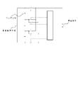
- FIG. 1 It is a figure which shows the basic structure of the power-source device for a general vehicle. It is a figure which shows the basic structure of the power supply device for a vehicle which concerns on embodiment of this invention.
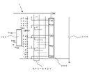
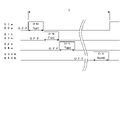
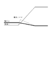
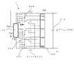
- FIG. 1 It is a figure which shows one Embodiment of the power supply device for a vehicle which concerns on embodiment of this invention. It is a figure explaining the power loss of a switching element. It is a figure explaining the power loss of a switching element. It is a figure explaining the charge / discharge depth of a power storage element. It is a figure which shows the other embodiment of the power supply device for a vehicle which concerns on embodiment of this invention. It is a figure explaining the method of supplying AC power to an electric load. It is a figure which shows the embodiment which was configured to boost the voltage of a power storage element.
- FIG. 2 is a basic embodiment of the present invention, wherein the vehicle power supply device 1 is charged by a power generation means (not shown) mechanically connected to a drive mechanism mounted on the vehicle and traveling by an engine and a motor. It is composed of power storage elements 1a to 40d composed of secondary batteries, switching means S1a to S40b, control means 200, electric leakage detecting means 100, and blocking means 500 and 501. Further, the vehicle power supply device 1 operates at 12 volts, and one end on the negative potential side is connected to an electric load 300 electrically connected to the vehicle body, and the high voltage load device 400 is connected via wire harnesses W1 and W2. To supply the power of the high-voltage power storage elements 1a to 40d to the high-voltage load device 400.
- FIG. 2 the figures of the power storage elements 3b to 39d, the switching means S3b to S39a connected to the power storage elements, and the portion where the switching means and the control means 200 are connected are omitted.
- the power generation means is driven by an engine (not shown) in order to supply the electric power required for the vehicle electrical components, and when the vehicle is reduced, the kinetic energy at the time of reduction is regenerated via the drive mechanism to charge the power storage elements 1a to 40d. It works as it does.
- Each node of the power storage elements 1a to 40d is, for example, a lithium ion battery having a charging voltage of 3 V. All the nodes of the power storage elements 1a to 40d are connected in series, and the required voltage 1 of the electric load 300 is 1.
- a high-voltage power supply of 480 volts in total is formed, where 40 is a multiple N with respect to 2 volts.
- the high-voltage power supply is supplied to the high-voltage load device 400 including a motor, an inverter, etc. mounted on the vehicle, and acts to assist the driving torque of the engine.
- the nodes 1a to 1d are used as the first group node, the nodes 2a to 2d are used as the second group node, the nodes 3a to 3d are used as the third group node, and finally 40a.
- the nodes from 40d to 40d are designated as the 40th group nodes, and the switching means S1a to S40b are connected to both ends of each group node.
- group nodes may simply be referred to as nodes.
- 200 is a control means and acts to control the on / off state of the switching means S1a to S40b and the on / off state of the cutoff means 500 and the cutoff means 501.
- the control means 200 turns on the switching means S1a and S2a and connects the electric load 300 and the first group node of the power storage element for the Ton time. At this time, the switching means other than the switching means S1a and S2a are turned off. Since the switching means S2a is connected to the positive electrode side of the first group node and the switching means S1a is connected to the negative electrode side of the first group node, a DC voltage of 12 volts is applied to the electric load 300 during Ton. It will be.
- the control means 200 keeps all the above-mentioned switching means S1a to S40b off during the period Td shown in FIG.
- the reason for providing the time Td is that, for example, when the switching means S1a and the switching means S1b are turned on at the same time, the switching means S1a, the switching means S1b, and the nodes 1a, 1b, 1c, and 1d of the power storage element are formed. This is because an excessive current flows through the closed circuit, resulting in damage to the switching means or wasteful consumption of the charging power of each power storage element.
- the switching means S1a to S40b actually respond when a signal for controlling the on / off of each switching means is transmitted from the control means 200. It is known that a time delay will occur by the time. Therefore, the control means 200 requires a sufficient waiting time Td from turning off the desired switching means to turning on the other switching means. This Td is called a dead time, and in the case of a general MOSFET, several tens of nanoseconds to several microseconds are required.
- the control means 200 turns on the switching means S1a and S2a between Tons and connects to the electric load 300 to provide the required voltage 12 to the electric load 300.
- the bolt is supplied, and then, in the second group node, it is connected to the electric load 300 between Tons via the switching means S1b and S3a, and in the third group node, it is connected to the ton via the switching means S2b and S4a.
- T in FIG. 3 is repeated as one cycle so as to be connected to the electric load 300 during Ton via the switching means S39b and S40b. Since it is assumed that the electric load 300 is continuously supplied with the DC power of 12 volts, the charge / discharge state of each of the first to 40th power storage element group nodes can be kept substantially uniform.
- the leakage detecting means 100 is connected to both ends of the power storage elements 1a to 40d via the terminal T102 and the terminal T101, and is grounded to the vehicle body via the terminal T103.
- the leakage detection means controls the leakage detection value from the terminal T100 to the larger of the current flowing between the terminal T101 and the ground terminal T103 and the current flowing between the terminal T102 and the ground terminal T103. It is configured to output to.
- the terminal T101 and the terminal T102 are floating with respect to the vehicle body, so that the leakage detection value is 0 amperes.
- the resistance value of the human body is about 5 K ⁇ , so that a leakage current is detected between the terminal T102 and the ground terminal T103.
- the leakage detection value ILeak of is larger than 0 amperes.
- the control means 200 incorporates the leakage detection value ILeak into the terminal T200 of the control means 200 via the terminal T100 of the leakage detection means 100, and when it is detected that the leakage is equal to or higher than the predetermined value ILth, FIG. 4 shows.
- the blocking means 500 and the blocking means 501 are turned off during the turn.
- the time Turn is set to infinity, and after that, the blocking means 500 and 501 may be kept off.
- the Toff is set to, for example, about 0.5 seconds, and the blocking means 500 and 50 are set. 1 and may be turned on again.
- the cutoff means 500 and 501 are turned on again, if the leakage detection value ILeek of the leakage detection means 100 in the dead time period Tdn exceeds ILth, it is determined that the human body is still in contact with the high voltage circuit. Then, as shown by the broken line showing the action of the blocking means 500 and 501 in FIG. 4, the blocking means 500 and 501 are turned off again to repeat on and off.
- the cutoff means 500 and 501 When the interruption means 500 and 501 are turned on again, if the leakage detection value ILeek of the leakage detection means 100 in the dead time period Tdn is less than ILth, it is determined that the human body is not in contact with the high voltage circuit. As shown by the solid line showing the operation of the cutoff means 500 and 501 in FIG. 4, the cutoff means 500 and 501 hold the on state and restart the supply of electric power to the high voltage load device 400.
- the cutoff means 500 and 501 Since the high voltage power supply supplied to the outside from the power storage elements 1a to 40d is cut off by the cutoff means 500 and 501, the high voltage current does not flow through the human body and electric shock can be prevented.
- a housing By surrounding the vehicle power supply device 1 with a housing (not shown), it is possible to prevent a human body from touching the inside of the vehicle power supply device 1 and receiving an electric shock.
- the control means 200 detects that the leakage resistance value RLak is equal to or higher than the first threshold value RLth1, the cutoff means 500 and the cutoff means 501 are continuously turned off. Then, when it is detected that the RLeak becomes larger than the first threshold value ILth1 and equal to or less than the second threshold value RLth2, the blocking means 500 and 501 may be turned on again.
- the power generation means limits the charging voltage of the power storage element so that the voltage obtained by connecting the entire nodes of the power storage elements 1a to 40d in series has a predetermined maximum value.
- the current consumption of the electric load 300 is not constant, and may change significantly in a short time depending on the operating state of the driver, for example, as in the case of electric power steering.
- the switching means S1a to S40b are controlled by the control means 200 and the first group node to the 40th group node of the power storage element are switched at equal intervals, a difference may occur in the charging state of each group node. ..
- control means 200 preferentially connects the high voltage group node to the electric load 300 while monitoring the voltage of each group node of the power storage element via the terminals T201, T202, T203 to T239, and T240 shown in FIG.
- the charging state of each storage element group (group node) is kept substantially uniform by selectively switching the storage element group (group node) to be discharged so that the group node having a low voltage is not connected to the electric load 300. be able to.
- the control means 200 monitors the voltage of each group node of the power storage element via the terminals T201, T202, T203 to T239, and T240 shown in FIG. Charging of the power storage element group (group node) so that the period in which the switching means is turned on is set long for the node and the period in which the switching means is turned on is set short for the group node having a low voltage. It is also possible to individually calculate and control Ton1 to Ton40 from the amount and the value of the current flowing through the electric load 300. As a result, the charging state of each power storage element group (group node) can be kept substantially uniform.
- the action of the earth leakage detecting means 100 is to determine the presence or absence of electric shock due to the contact of the human body with the high voltage portion during the period Ton when any two of the switching means S1a to S40b of FIG. 4 are on.
- the earth leakage detection means 100 and the earth leakage detection means 501 are detected depending on whether or not the leakage detection value of the leakage detection means 100 in the dead time period Td at the moment when any two of the switching means are turned off is ILth or more. Since and is turned off, the maximum time that the electric shock current actually flows to the human body is Ton.
- the Ton time needs to be within the range in which the electric shock current determined by the voltage value of the high voltage power supply by the power storage elements 1a to 40d and the resistance value of the human body and the human body reaction expected from the duration thereof are harmless to the human body. It is generally said that there is no fatal human reaction if the electric shock time is 0.1 seconds or less when the current value is 30 mA. That is, it is said that the maximum value of the product of the electric shock current and the electric shock time is 0.003 amperes seconds in order to suppress the reaction to a safe human body.
- the maximum electric shock current is about 100 mA from the voltage value of the high voltage power supply of 480 volts and the human body resistance of 5 K ⁇ , and the electric shock time without harm to the human body is calculated to be 0.03 seconds or less. Therefore, the maximum value of Ton during the period when any two of the switching means S1a to S40b are on is set to 0.001 seconds, which is a small value with sufficient margin.
- a system equipped with a vehicle's high-voltage power supply is not only when the human body touches the high-voltage circuit part, but also temporarily leaks due to leakage of the mounted electronic parts, malfunction of the insulating part, vibration during running, etc. Current may flow. In such a case, if the power supply from the high voltage power source to the high voltage load device 400 is completely stopped by the action of the control means 200, the function of each part may be lost while the vehicle is running, which may be dangerous.
- the control means 200 sets the state in which the cutoff means 500 and 501 are off when the leakage detection value ILeek of the leakage detection means 100 is equal to or higher than the predetermined current value ILth. After holding for a second or longer, the operation of turning on the blocking means 500 and 501 was repeated.
- the control means 200 holds the cutoff means 500 and 501 off for 0.5 seconds or longer, and then cuts off again.
- the energization time Ton after restarting is shortened in inverse proportion to the voltage value of the high voltage power supply by the power storage elements 1a to 40d, and / or the leakage detecting means 100 determines. It is desirable to shorten it in inverse proportion to the detected leakage current value.
- the leakage is not caused by the vehicle but is an electric shock to the human body
- the higher the voltage of the high-voltage power supply the shorter the energization time to the human body, and / or the larger the electric shock current of the human body, the longer the energization time to the human body. Is shortened, which improves safety.
- control means 200 switches each group node in the period T to supply a predetermined low voltage power supply to the electric load 300, and the power generation means (not shown) is a series storage element 1a to 4 It is assumed that the battery is constantly charged so that the total voltage of 0d becomes a predetermined value.
- the group node is in a discharged state due to the current flowing through the electric load 300 during the on period.
- the charging voltage drops.
- the charging current is supplied from the power generation means so that the total voltage of all the storage elements 1a to 40d becomes constant, so that the voltage changes in the increasing direction.
- the difference between the maximum voltage and the minimum voltage at the specific group node is the so-called charge / discharge depth, and when this width becomes large, the life of the power storage element is shortened.
- the electric load 300 selectively selects the electric storage element group (group node) by the control means 200 from the viewpoint of the life of the electric storage element as well as shortening the ton. It can be seen that the time Ton connected to the device should be shortened and the control cycle T that goes through the selection of all the energy storage element groups (group nodes) should be shortened.
- the switching loss in the switching means S1a to S40b is such that the voltage V across the switching means in the on-transition process of each switching means in the open state is accompanied by the on-operation.
- the current I increases in conjunction with the decrease.
- the switching loss occurs during the dead time Td
- the average value of the switching loss with respect to the control cycle T of the control means 200 is Td / T. Therefore, the control cycle T should be shortened as described above. Therefore, there is a problem that the switching loss becomes excessive.
- the voltage VL applied to the electric load 300 during the dead time Td period shown in FIG. 3 is 0 volt during the period when the switching means S1a to S40b are all off. Therefore, since the power supplied to the electric load 300 is momentarily interrupted, there is a problem that the low voltage vehicle electric load is momentarily stopped.
- a capacitor 310 is arranged in parallel with the electric load 300.
- the voltage charged in the capacitor 310 continues to be supplied to the electric load 300, so that the voltage VL does not drop to 0 volt, but is limited to a slight voltage drop from the peak voltage as shown by the broken line VLa in FIG. be able to.
- the amount of voltage drop in this case is determined by the current flowing through the electric load 300, the capacity of the capacitor 310, and the dead time Td. When the dead time Td and the current flowing through the electric load 300 are fixed, the capacitor 310 The larger the capacity, the smaller the amount of VLa drop.
- the amount of VLa drop is determined by the capacity of the capacitor 310, the dead time Td, and the current value flowing through the electric load 300, if the capacity of the capacitor 310 is specified, the dead time Td is shortened. Needless to say, the amount of VLa drop can be reduced.
- the total voltage of the series storage elements in the group node of the storage elements connected by turning on any of the switching means is 12 volts.
- the voltage of the capacitor 310 is approximately 12 volts, the voltage across the switching means can be set to approximately 0 volts when the switching means is in the open state, so that the switching loss in this case is shown in FIG. As shown in the above, since the current I increases while the voltage V remains approximately 0 volt, the loss I ⁇ V becomes extremely small.
- the voltage of one group node of the power storage element is output as a voltage to be supplied to the electric load 300, and the voltage of each group node is obtained by utilizing the fact that the capacitor 310 holds the voltage of the group node. If is the same, the voltage of each group node for switching all group nodes and the voltage of the electric load 300 (capacitor 310) are the same, so that the operation of the switching means is so-called ZVS (known zero volt switching). In theory, no switching loss will occur.
- the switching loss is not generated at the time of stepping down from the high voltage power supply to the low voltage power supply, the heat loss generated by the switching element used for stepping down is extremely reduced, and the output is 2.5 kW in the experiments of the inventors.
- the power conversion efficiency was 99.5%, which made it possible to significantly reduce the system cost, such as eliminating the need for a heat sink.
- the control means 200 does not stop the power supply to the high voltage load device 400 due to the leakage current detection caused by the vehicle, and at the same time avoids the danger due to the electric shock current to the human body.
- the detected value ILeak is equal to or higher than the predetermined current value ILth
- the shutoff means 500 and 501 are kept off for, for example, 0.5 seconds (predetermined time) or longer, and then the cutoff means 500 and 501 are turned on again. repeat.
- the high voltage so as to maintain the voltage supplied to the high voltage load device 400 even during the stop period. It is preferable to dispose a capacitor (not shown) having a desired capacitance in parallel with the voltage load device 400.
- capacitors 601 and 602 are used at both ends of each storage element group (group node) formed by connecting four nodes of the storage elements 1a to 40d in series. ⁇ 640 were connected and configured.
- the power storage element has an equivalent series resistance value of several tens of m ⁇ as an internal resistance (not shown) when, for example, a lithium ion battery is adopted. Therefore, in the case of four series power storage elements in one group node in the present embodiment, an internal resistance of about 100 m ⁇ is provided for each group node of the power storage element.
- the electrical time constant of the rising portion is the capacitance of the capacitor 310.
- the rising waveform of VL when the capacitor 310 is charged by the internal resistance of the power storage element has a large time constant and a low voltage state continues for a long time. Further, since this is repeated in the period T, it causes a factor that the average value of the voltage supplied to the electric load 300 decreases, so it is desirable that the time constant is as small as possible.
- the equivalent series resistance of a capacitor as a capacitance element is as small as several m ⁇ . Therefore, when the capacitors 601 and 602 to 640 are connected in parallel with each group node of the power storage element as in the present embodiment, the internal resistance of the power storage element is apparently reduced, and the capacitor 310 is charged by the internal resistance. As shown by VLc in FIG. 3, the rising waveform of VL in this case has a small time constant and a short state in which the voltage is low. Since this is repeated in the period T, the decrease in the average value of the voltage supplied to the electric load 300 is small, and the accuracy of the voltage supplied to the electric load 300 is improved.
- the power storage element 180 lithium-ion batteries having a cell voltage of 3 volts are connected in series, and the total voltage is 540 volts.
- the 60 power storage elements are regarded as one group node, and the whole is divided into three group nodes G1 to G3, and the voltage of each group node is switched every 1 millisecond by the switching means to supply the commercial power supply load.
- the selected group node is G1
- G2 is selected and supplied to the commercial power load
- the storage element group for connecting to the commercial power load. Operate the switching means so that the polarity of (group node) is reversed.
- the vehicle power supply device selectively connects a predetermined power storage element group (group node) to a low voltage electric load from a high voltage power supply formed by connecting power storage elements in series.
- group node a predetermined power storage element group
- the charge / discharge depth of the power storage element is reduced and the life is improved.
- the switching loss of the switching means for switching can be made substantially zero, it has an excellent feature that the weight and cost of the member required for heat dissipation of the switching element can be significantly improved.
- dangerous human body reaction can be suppressed even when the human body touches the high voltage power supply circuit part without using means such as an isolated DC-DC converter.
- the voltage of the power storage element can be boosted and supplied to the electric load means.
- the capacitor is a node, and the voltage of the power storage element is charged to each node, so that the boosted power is taken out from the capacitors connected in series.
Landscapes
- Engineering & Computer Science (AREA)
- Power Engineering (AREA)
- Mechanical Engineering (AREA)
- Transportation (AREA)
- Life Sciences & Earth Sciences (AREA)
- Sustainable Development (AREA)
- Sustainable Energy (AREA)
- Charge And Discharge Circuits For Batteries Or The Like (AREA)
- Electric Propulsion And Braking For Vehicles (AREA)
- Emergency Protection Circuit Devices (AREA)
- Protection Of Static Devices (AREA)
Abstract
Description
その為、車両の一般的な高電圧システムにおいては図1に示すように高電圧部位と低電圧部位との間に絶縁トランスを備えたDC-DCコンバータを配置すると共に、高電圧回路は車体との直接接続を避けて負電位回路と正電位回路の双方をフローティングとすることで、人体が高電圧蓄電手段を含む回路部分のいずれの部位に触っても感電しない構成となっている。
2ボルト電源のボディーアースとして車体に接続されることになるから、スイッチ手段30~35の内、いずれか1つ以上が閉じている場合には高電圧側の直列に接続された蓄電手段20a~20Lの接続点のどこかが車体と直接接続されるので、人体が高電圧回路に触れると感電する。具体的には、蓄電手段20a~20Lの直列合計電圧が仮に480ボルトであるとして、スイッチ手段35が閉じている瞬間に蓄電手段20aの正電位側と車体との間に触れると人体に480ボルトの高電圧が印加されて感電事故が発生する可能性が考えられる。
)個接続して、前記所定低電圧のN倍の高電圧の直流電源を得る。
、再度、前記遮断手段をオンとする動作を繰り返す。
従って、スイッチング手段の構成が簡略化可能であるとともに、公知のスイッチング損失やインダクターから発生する損失を大幅に低減できるから、降圧のための電力損失を低減して放熱構造を簡略化し、その結果、かかる降圧のための装置を含む電源装置の重量とコストを低減できる。
しかしながら制御手段は、全てのスイッチング手段がオフとなったデッドタイム期間中に高電圧電源から人体を介して流れる電流を漏電検出手段の測定電流値として検出し、その値が所定値以上である場合には、車両用電源装置から外部と接続されたワイヤーハーネスを介して高電圧負荷装置と接続した電気回路を切り離す遮断手段をオフ状態として保持するので感電事故を防止することができる。
従って、一般的な商用電源に用いられる漏電遮断器においては30ミリアンペア×0.
1秒の漏電検出感度が設定されている。
.1秒以下と同程度の安全水準を確保することができる。
その為、スイッチング手段が切り替わるタイミングにおける電気負荷へ供給される電圧の低下が避けられない。
図2は、本発明にかかる基本的な実施態様であり、車両用電源装置1は、車両に搭載してエンジンとモータによって走行を行う駆動機構と機械的に連結された図示しない発電手段によって充電される二次電池からなる蓄電素子1a~40dと、スイッチング手段S1a~S40b、制御手段200、漏電検出手段100、遮断手段500、501とから構成される。また、車両用電源装置1は12ボルトで作動するとともに負電位側の一端が車体と電気的に接続された電気負荷300と接続されるとともに、ワイヤーハーネスW1、W2を介して高電圧負荷装置400と接続して高電圧の蓄電素子1a~40dの電力を高電圧負荷装置400へ供給する。
、該蓄電素子1aから40dの全ノードを直列に接続して、電気負荷300の要求電圧1
2ボルトに対する倍数Nを40として、合計480ボルトの高圧電源が形成される。また、該高圧電源は車載されたモータ、インバータ等から成る高電圧負荷装置400へ供給して、エンジンの駆動トルクをアシストするように作用する。これによって、車両の力行時には、減 時に回生したエネルギーを再利用して走行できるから車両の走行燃費向上を図ることが可能になる。
。
ここで、第1から第40の各グループノードにおける直列蓄電素子の合計電圧は3ボルト×4=12ボルトとなる。
。
漏電検出手段100は端子T102と端子T101とを介して蓄電素子1a~40dの両端と接続するとともに、端子T103を経由して車体へ接地してある。ここで、該漏電検出手段は端子T101と接地端子T103との間に流れる電流と、端子T102と接地端子T103との間に流れる電流のうち、大きい方の漏電検出値を端子T100から制御手段200へ出力するように構成してある。
501はオフ状態を維持しても良い。
或いは、図4で示す如くToffを例えば0.5秒程度に設定し、遮断手段500と50
1とを再度オンにしても良い。
即ち、安全な人体反応に抑制するには感電電流と感電時間との積の最大値が0.003アンペア秒であるとされている。
0dの合計電圧が所定の値となるように常時充電しているものとする。
これによって、コンデンサ310に充電された電圧が電気負荷300へ供給され続けることから、電圧VLは0ボルトまで降下することなく、図3の破線VLaで示す如く、ピーク電圧から僅かの電圧降下に留めることができる。この場合の電圧降下量は、電気負荷300へ流れる電流と、コンデンサ310の容量と、デッドタイムTdとによって決まり、該デッドタイムTdと電気負荷300へ流れる電流を固定した場合には該コンデンサ310の容量が大きい程、VLaの降下量を小さくすることができる。
Vが略0ボルトのまま電流Iが増加するので損失I×Vは極小となる。
S1a~S40b スイッチング手段
100 漏電検出手段
200 制御手段
300 電気負荷
400 高電圧負荷装置
500、501 遮断手段
Claims (16)
- 所定低電圧で作動する電気負荷と、前記所定低電圧を供給する各ノードを構成する複数の蓄電素子を直列に接続して高電圧の直流電源を得る高電圧電源と、ワイヤーハーネスを介して高電圧電源と接続された高電圧負荷装置と、前記電気負荷に前記所定低電圧を供給する各ノードに対応して設けられた複数のスイッチ手段と、少なくとも1のノードからの電圧を供給する前記スイッチ手段をオンし、他のノードからの電圧を供給する前記スイッチ手段をオフにすることで電圧を供給するとともに、一旦全てのスイッチ手段をオフにするデッドタイム期間を設けた後、次に電圧を供給するノードの前記スイッチ手段をオンとし、他のノードからの電圧を供給するスイッチ手段をオフにする制御を順次繰り返すことで、全ての前記蓄電素子から電圧を供給させる制御手段と、前記高電圧電源と高電圧負荷装置との間の電気回路を遮断する遮断手段と、高電圧電源と接地電位との間の漏電電流を検出して前記制御手段に信号を送出する漏電検出手段と、を備えた車両用電源装置であって、前記制御手段が、前記複数のスイッチング手段が全てオフ状態である前記デッドタイム期間に前記漏電検出手段から送出される信号を判定し、漏電電流が所定の電流以上である場合には、前記遮断手段をオフにした状態を所定期間保持することを特徴とする車両用電源装置。
- 前記高電圧電源は、n個(n:自然数)で前記所定低電圧となるノードを構成する複数の蓄電素子を直列に(n×N(N:自然数))個接続して、前記所定低電圧のN倍の高電圧の直流電源を得ることを特徴とする請求項1に記載の車両用電源装置。
- 前記制御手段は、前記選択する複数のノードを周期的に変更するように前記スイッチ手段を制御することを特徴とする請求項1に記載の車両用電源装置。
- 前記制御手段は、前記複数の蓄電素子の充放電状態が略均一となるように、前記選択するノードを決定することを特徴とする請求項3に記載の車両用電源装置。
- 前記制御手段は、前記複数の蓄電素子の充放電状態が略均一となるように、各ノードの選択保持時間を決定することを特徴とする請求項3に記載の車両用電源装置。
- 前記スイッチング手段によって前記各ノードのいずれかと前記電気負荷とを接続する時間を、前記高電圧電源から人体に流れる漏電電流の継続時間が、人体の感電事故が起きる時間未満となるように設定したことを特徴とする請求項1から請求項5のいずれか1項に記載の車両用電源装置。
- 前記スイッチング手段が前記各ノードと前記電気負荷とを接続している時間を、前記高電圧電源の電圧値に反比例した継続時間、又は、前記漏電検出手段が検出する電流値に反比例した継続時間とすることを特徴とする請求項6に記載の車両用電源装置。
- 前記制御手段は、前記漏電検出手段の漏電検出値が所定の電流値以上の時、前記遮断手段をオフの状態に固定することを特徴とする請求項1から請求項7のいずれか1項に記載の車両用電源装置。
- 前記制御手段は、前記漏電検出手段の漏電検出値が所定の電流値以上の時、前記遮断手段がオフである状態を所定の時間保持した後、再度、前記遮断手段がオンとなる動作を繰り返すことを特徴とする請求項1から請求項7のいずれか1項に記載の車両用電源装置。
- 前記制御手段は、前記漏電検出手段の漏電検出値が第一の閾値以上の時、前記遮断手段をオフとし、該漏電検出値が第一の閾値より小さい第二の閾値以下となった場合に、再度、前記遮断手段をオンとする動作を繰り返すことを特徴とする請求項1から請求項7のいずれか1項に記載の車両用電源装置。
- 前記制御手段は、前記各ノードと前記電気負荷とを接続している期間と前記漏電検出手段の漏電検出値との積が0.003アンペア×1秒以下となるように前記スイッチング手段を制御することを特徴とする請求項1から請求項9のいずれか1項に記載の車両用電源装置。
- 前記制御手段は、前記蓄電素子の各ノードにおける充放電深度の大きさが所定値以下となるように、前記スイッチング手段が選択するノードを切り替える周期を所定値以下に設定することを特徴とする請求項1から請求項11のいずれか1項に記載の車両用電源装置。
- 前記電気負荷と並列にコンデンサが接続されることを特徴とする請求項1から請求項12のいずれか1項に記載の車両用電源装置。
- 前記デッドタイム期間、又は、前記コンデンサの容量値は、該デッドタイム期間中に前記電気負荷に印加される電圧の低下幅が所定値以下となるように設定されることを特徴とする請求項13に記載の車両用電源装置。
- 前記蓄電素子の各ノードと並列にコンデンサが配設されることを特徴とする請求項13又は請求項14に記載の車両用電源装置。
- 前記複数の蓄電素子を直列に接続して高電圧の直流電源を得る高電圧電源の前記各ノードから、前記スイッチング手段によって前記電気負荷と接続する際の高電位側と低電位側との極性を所定期間ごとに交互に反転することによって、該電気負荷へ交流電力を供給することを特徴とする請求項1から請求項15のいずれか1項に記載の車両用電源装置。
Priority Applications (3)
| Application Number | Priority Date | Filing Date | Title |
|---|---|---|---|
| EP21885750.6A EP4238805B1 (en) | 2020-11-02 | 2021-09-17 | Vehicle power source device |
| US18/249,265 US12097775B2 (en) | 2020-11-02 | 2021-09-17 | Power supply device for vehicle |
| CN202180070318.5A CN116323285A (zh) | 2020-11-02 | 2021-09-17 | 车辆用电源装置 |
Applications Claiming Priority (2)
| Application Number | Priority Date | Filing Date | Title |
|---|---|---|---|
| JP2020183512A JP7578874B2 (ja) | 2020-11-02 | 2020-11-02 | 車両用電源装置 |
| JP2020-183512 | 2020-11-02 |
Publications (1)
| Publication Number | Publication Date |
|---|---|
| WO2022091631A1 true WO2022091631A1 (ja) | 2022-05-05 |
Family
ID=81382263
Family Applications (1)
| Application Number | Title | Priority Date | Filing Date |
|---|---|---|---|
| PCT/JP2021/034276 Ceased WO2022091631A1 (ja) | 2020-11-02 | 2021-09-17 | 車両用電源装置 |
Country Status (5)
| Country | Link |
|---|---|
| US (1) | US12097775B2 (ja) |
| EP (1) | EP4238805B1 (ja) |
| JP (1) | JP7578874B2 (ja) |
| CN (1) | CN116323285A (ja) |
| WO (1) | WO2022091631A1 (ja) |
Families Citing this family (2)
| Publication number | Priority date | Publication date | Assignee | Title |
|---|---|---|---|---|
| JP7568908B2 (ja) * | 2020-11-02 | 2024-10-17 | 株式会社今仙電機製作所 | 車両用電源装置 |
| JP7748632B2 (ja) * | 2022-03-02 | 2025-10-03 | 株式会社今仙電機製作所 | 車両用電源装置 |
Citations (5)
| Publication number | Priority date | Publication date | Assignee | Title |
|---|---|---|---|---|
| JP2013134120A (ja) * | 2011-12-26 | 2013-07-08 | Mitsubishi Heavy Ind Ltd | 電池システム |
| JP2017118813A (ja) * | 2015-12-21 | 2017-06-29 | 三星電子株式会社Samsung Electronics Co.,Ltd. | バッテリ制御方法、バッテリ制御装置、及びバッテリパック |
| JP2017123327A (ja) * | 2016-01-05 | 2017-07-13 | 三星電子株式会社Samsung Electronics Co.,Ltd. | バッテリ制御装置及びバッテリ制御システム |
| JP2018026973A (ja) | 2016-08-12 | 2018-02-15 | 株式会社今仙電機製作所 | 車両用電源装置 |
| JP2020031471A (ja) * | 2018-08-21 | 2020-02-27 | スズキ株式会社 | 車載電源装置 |
Family Cites Families (8)
| Publication number | Priority date | Publication date | Assignee | Title |
|---|---|---|---|---|
| JP5349021B2 (ja) * | 2008-11-26 | 2013-11-20 | 三洋電機株式会社 | バッテリシステム |
| JP5348330B2 (ja) * | 2011-09-21 | 2013-11-20 | トヨタ自動車株式会社 | 電動車両の充電システムおよび充電制御方法 |
| US9789764B2 (en) * | 2012-03-07 | 2017-10-17 | International Truck Intellectual Property Company, Llc | Vehicle electrical system state controller |
| DE102012220549A1 (de) * | 2012-11-12 | 2014-05-15 | Siemens Aktiengesellschaft | Elektro-Transportmittel, zugehöriges Verfahren und zugehöriger Akkumulator |
| JP7320737B2 (ja) * | 2018-09-06 | 2023-08-04 | パナソニックIpマネジメント株式会社 | 均等化回路、及び蓄電システム |
| US11971458B2 (en) * | 2019-02-19 | 2024-04-30 | Sanyo Electric Co., Ltd. | Electrical fault detection device and vehicle power supply system |
| JP7518333B2 (ja) * | 2020-01-20 | 2024-07-18 | 株式会社今仙電機製作所 | 車両用電源装置 |
| JP7560715B2 (ja) * | 2020-04-01 | 2024-10-03 | 株式会社今仙電機製作所 | 車両用電源装置 |
-
2020
- 2020-11-02 JP JP2020183512A patent/JP7578874B2/ja active Active
-
2021
- 2021-09-17 EP EP21885750.6A patent/EP4238805B1/en active Active
- 2021-09-17 CN CN202180070318.5A patent/CN116323285A/zh active Pending
- 2021-09-17 US US18/249,265 patent/US12097775B2/en active Active
- 2021-09-17 WO PCT/JP2021/034276 patent/WO2022091631A1/ja not_active Ceased
Patent Citations (5)
| Publication number | Priority date | Publication date | Assignee | Title |
|---|---|---|---|---|
| JP2013134120A (ja) * | 2011-12-26 | 2013-07-08 | Mitsubishi Heavy Ind Ltd | 電池システム |
| JP2017118813A (ja) * | 2015-12-21 | 2017-06-29 | 三星電子株式会社Samsung Electronics Co.,Ltd. | バッテリ制御方法、バッテリ制御装置、及びバッテリパック |
| JP2017123327A (ja) * | 2016-01-05 | 2017-07-13 | 三星電子株式会社Samsung Electronics Co.,Ltd. | バッテリ制御装置及びバッテリ制御システム |
| JP2018026973A (ja) | 2016-08-12 | 2018-02-15 | 株式会社今仙電機製作所 | 車両用電源装置 |
| JP2020031471A (ja) * | 2018-08-21 | 2020-02-27 | スズキ株式会社 | 車載電源装置 |
Non-Patent Citations (1)
| Title |
|---|
| See also references of EP4238805A4 |
Also Published As
| Publication number | Publication date |
|---|---|
| EP4238805A1 (en) | 2023-09-06 |
| US12097775B2 (en) | 2024-09-24 |
| EP4238805A4 (en) | 2024-10-09 |
| CN116323285A (zh) | 2023-06-23 |
| US20230391201A1 (en) | 2023-12-07 |
| JP2022073491A (ja) | 2022-05-17 |
| EP4238805B1 (en) | 2026-03-04 |
| JP7578874B2 (ja) | 2024-11-07 |
Similar Documents
| Publication | Publication Date | Title |
|---|---|---|
| EP4096040B1 (en) | Vehicle power supply | |
| US11945313B2 (en) | Power supply device for vehicle | |
| US11949259B2 (en) | Power supply device for vehicle | |
| US11904706B2 (en) | Power supply device for vehicle | |
| EP4238805B1 (en) | Vehicle power source device | |
| JP5404712B2 (ja) | 充電装置、車載用充電装置、車載用充電装置における充電方法 | |
| US12109899B2 (en) | Power supply device for vehicle | |
| CN106160040B (zh) | 车用二次锂电池 |
Legal Events
| Date | Code | Title | Description |
|---|---|---|---|
| 121 | Ep: the epo has been informed by wipo that ep was designated in this application |
Ref document number: 21885750 Country of ref document: EP Kind code of ref document: A1 |
|
| WWE | Wipo information: entry into national phase |
Ref document number: 18249265 Country of ref document: US |
|
| NENP | Non-entry into the national phase |
Ref country code: DE |
|
| ENP | Entry into the national phase |
Ref document number: 2021885750 Country of ref document: EP Effective date: 20230602 |
|
| WWG | Wipo information: grant in national office |
Ref document number: 2021885750 Country of ref document: EP |