WO2022091766A1 - 複合材料 - Google Patents
複合材料 Download PDFInfo
- Publication number
- WO2022091766A1 WO2022091766A1 PCT/JP2021/037683 JP2021037683W WO2022091766A1 WO 2022091766 A1 WO2022091766 A1 WO 2022091766A1 JP 2021037683 W JP2021037683 W JP 2021037683W WO 2022091766 A1 WO2022091766 A1 WO 2022091766A1
- Authority
- WO
- WIPO (PCT)
- Prior art keywords
- layer
- tungsten
- iron
- intermediate layer
- mass
- Prior art date
- Legal status (The legal status is an assumption and is not a legal conclusion. Google has not performed a legal analysis and makes no representation as to the accuracy of the status listed.)
- Ceased
Links
Images


Classifications
-
- C—CHEMISTRY; METALLURGY
- C22—METALLURGY; FERROUS OR NON-FERROUS ALLOYS; TREATMENT OF ALLOYS OR NON-FERROUS METALS
- C22C—ALLOYS
- C22C9/00—Alloys based on copper
- C22C9/06—Alloys based on copper with nickel or cobalt as the next major constituent
-
- B—PERFORMING OPERATIONS; TRANSPORTING
- B23—MACHINE TOOLS; METAL-WORKING NOT OTHERWISE PROVIDED FOR
- B23K—SOLDERING OR UNSOLDERING; WELDING; CLADDING OR PLATING BY SOLDERING OR WELDING; CUTTING BY APPLYING HEAT LOCALLY, e.g. FLAME CUTTING; WORKING BY LASER BEAM
- B23K20/00—Non-electric welding by applying impact or other pressure, with or without the application of heat, e.g. cladding or plating
-
- B—PERFORMING OPERATIONS; TRANSPORTING
- B23—MACHINE TOOLS; METAL-WORKING NOT OTHERWISE PROVIDED FOR
- B23K—SOLDERING OR UNSOLDERING; WELDING; CLADDING OR PLATING BY SOLDERING OR WELDING; CUTTING BY APPLYING HEAT LOCALLY, e.g. FLAME CUTTING; WORKING BY LASER BEAM
- B23K35/00—Rods, electrodes, materials, or media, for use in soldering, welding, or cutting
- B23K35/001—Interlayers, transition pieces for metallurgical bonding of workpieces
- B23K35/004—Interlayers, transition pieces for metallurgical bonding of workpieces at least one of the workpieces being of a metal of the iron group
-
- B—PERFORMING OPERATIONS; TRANSPORTING
- B23—MACHINE TOOLS; METAL-WORKING NOT OTHERWISE PROVIDED FOR
- B23K—SOLDERING OR UNSOLDERING; WELDING; CLADDING OR PLATING BY SOLDERING OR WELDING; CUTTING BY APPLYING HEAT LOCALLY, e.g. FLAME CUTTING; WORKING BY LASER BEAM
- B23K35/00—Rods, electrodes, materials, or media, for use in soldering, welding, or cutting
- B23K35/001—Interlayers, transition pieces for metallurgical bonding of workpieces
- B23K35/005—Interlayers, transition pieces for metallurgical bonding of workpieces at least one of the workpieces being of a refractory metal
-
- B—PERFORMING OPERATIONS; TRANSPORTING
- B23—MACHINE TOOLS; METAL-WORKING NOT OTHERWISE PROVIDED FOR
- B23K—SOLDERING OR UNSOLDERING; WELDING; CLADDING OR PLATING BY SOLDERING OR WELDING; CUTTING BY APPLYING HEAT LOCALLY, e.g. FLAME CUTTING; WORKING BY LASER BEAM
- B23K35/00—Rods, electrodes, materials, or media, for use in soldering, welding, or cutting
- B23K35/22—Rods, electrodes, materials, or media, for use in soldering, welding, or cutting characterised by the composition or nature of the material
- B23K35/24—Selection of soldering or welding materials proper
- B23K35/30—Selection of soldering or welding materials proper with the principal constituent melting at less than 1550°C
- B23K35/3033—Ni as the principal constituent
-
- B—PERFORMING OPERATIONS; TRANSPORTING
- B32—LAYERED PRODUCTS
- B32B—LAYERED PRODUCTS, i.e. PRODUCTS BUILT-UP OF STRATA OF FLAT OR NON-FLAT, e.g. CELLULAR OR HONEYCOMB, FORM
- B32B15/00—Layered products comprising a layer of metal
- B32B15/01—Layered products comprising a layer of metal all layers being exclusively metallic
-
- B—PERFORMING OPERATIONS; TRANSPORTING
- B32—LAYERED PRODUCTS
- B32B—LAYERED PRODUCTS, i.e. PRODUCTS BUILT-UP OF STRATA OF FLAT OR NON-FLAT, e.g. CELLULAR OR HONEYCOMB, FORM
- B32B15/00—Layered products comprising a layer of metal
- B32B15/01—Layered products comprising a layer of metal all layers being exclusively metallic
- B32B15/013—Layered products comprising a layer of metal all layers being exclusively metallic one layer being formed of an iron alloy or steel, another layer being formed of a metal other than iron or aluminium
-
- B—PERFORMING OPERATIONS; TRANSPORTING
- B32—LAYERED PRODUCTS
- B32B—LAYERED PRODUCTS, i.e. PRODUCTS BUILT-UP OF STRATA OF FLAT OR NON-FLAT, e.g. CELLULAR OR HONEYCOMB, FORM
- B32B15/00—Layered products comprising a layer of metal
- B32B15/01—Layered products comprising a layer of metal all layers being exclusively metallic
- B32B15/013—Layered products comprising a layer of metal all layers being exclusively metallic one layer being formed of an iron alloy or steel, another layer being formed of a metal other than iron or aluminium
- B32B15/015—Layered products comprising a layer of metal all layers being exclusively metallic one layer being formed of an iron alloy or steel, another layer being formed of a metal other than iron or aluminium the said other metal being copper or nickel or an alloy thereof
-
- C—CHEMISTRY; METALLURGY
- C22—METALLURGY; FERROUS OR NON-FERROUS ALLOYS; TREATMENT OF ALLOYS OR NON-FERROUS METALS
- C22C—ALLOYS
- C22C19/00—Alloys based on nickel or cobalt
- C22C19/03—Alloys based on nickel or cobalt based on nickel
-
- C—CHEMISTRY; METALLURGY
- C22—METALLURGY; FERROUS OR NON-FERROUS ALLOYS; TREATMENT OF ALLOYS OR NON-FERROUS METALS
- C22C—ALLOYS
- C22C19/00—Alloys based on nickel or cobalt
- C22C19/07—Alloys based on nickel or cobalt based on cobalt
-
- C—CHEMISTRY; METALLURGY
- C22—METALLURGY; FERROUS OR NON-FERROUS ALLOYS; TREATMENT OF ALLOYS OR NON-FERROUS METALS
- C22C—ALLOYS
- C22C38/00—Ferrous alloys, e.g. steel alloys
-
- C—CHEMISTRY; METALLURGY
- C22—METALLURGY; FERROUS OR NON-FERROUS ALLOYS; TREATMENT OF ALLOYS OR NON-FERROUS METALS
- C22C—ALLOYS
- C22C38/00—Ferrous alloys, e.g. steel alloys
- C22C38/10—Ferrous alloys, e.g. steel alloys containing cobalt
-
- B—PERFORMING OPERATIONS; TRANSPORTING
- B32—LAYERED PRODUCTS
- B32B—LAYERED PRODUCTS, i.e. PRODUCTS BUILT-UP OF STRATA OF FLAT OR NON-FLAT, e.g. CELLULAR OR HONEYCOMB, FORM
- B32B2307/00—Properties of the layers or laminate
- B32B2307/70—Other properties
- B32B2307/732—Dimensional properties
-
- C—CHEMISTRY; METALLURGY
- C22—METALLURGY; FERROUS OR NON-FERROUS ALLOYS; TREATMENT OF ALLOYS OR NON-FERROUS METALS
- C22C—ALLOYS
- C22C27/00—Alloys based on rhenium or a refractory metal not mentioned in groups C22C14/00 or C22C16/00
- C22C27/04—Alloys based on tungsten or molybdenum
-
- Y—GENERAL TAGGING OF NEW TECHNOLOGICAL DEVELOPMENTS; GENERAL TAGGING OF CROSS-SECTIONAL TECHNOLOGIES SPANNING OVER SEVERAL SECTIONS OF THE IPC; TECHNICAL SUBJECTS COVERED BY FORMER USPC CROSS-REFERENCE ART COLLECTIONS [XRACs] AND DIGESTS
- Y10—TECHNICAL SUBJECTS COVERED BY FORMER USPC
- Y10T—TECHNICAL SUBJECTS COVERED BY FORMER US CLASSIFICATION
- Y10T428/00—Stock material or miscellaneous articles
- Y10T428/12—All metal or with adjacent metals
- Y10T428/12493—Composite; i.e., plural, adjacent, spatially distinct metal components [e.g., layers, joint, etc.]
- Y10T428/12771—Transition metal-base component
- Y10T428/12806—Refractory [Group IVB, VB, or VIB] metal-base component
- Y10T428/12826—Group VIB metal-base component
- Y10T428/1284—W-base component
Definitions
- the composite material is disclosed in, for example, Japanese Patent Application Laid-Open No. 2000-246549 (Patent Document 1).
- the composite material of the present disclosure comprises an iron-based alloy layer, an intermediate layer provided on the iron-based alloy layer, and a layer containing tungsten provided on the intermediate layer, and the intermediate layer is made of pure nickel.
- the intermediate layer is composed of an alloy containing at least one selected from the group consisting of copper, cobalt and iron in a total amount of more than 0% by mass and 71% by mass or less, and nickel in an amount of 29% by mass or more and less than 100% by mass.
- FIG. 1 is a cross-sectional view of the composite material 1 according to the embodiment.
- FIG. 2 is a cross-sectional view of a jig and a composite material fixed to the jig for explaining a method of evaluating the joint strength.
- FIG. 3 is a cross-sectional view of a fixed base and a composite material fixed to the fixed base for explaining a method of evaluating heat resistance.
- the composite material of the present disclosure comprises an iron-based alloy layer, an intermediate layer provided on the iron-based alloy layer, and a layer containing tungsten provided on the intermediate layer, and the intermediate layer is made of pure nickel.
- the intermediate layer is composed of an alloy containing at least one selected from the group consisting of copper, cobalt and iron in a total amount of more than 0% by mass and 71% by mass or less, and nickel in an amount of 29% by mass or more and less than 100% by mass.
- the laminated structure of an iron-based alloy layer, an intermediate layer, and a layer containing tungsten is hereinafter referred to as a tungsten-iron-based alloy clad material.
- the thickness of the layer containing tungsten of the tungsten-iron alloy clad material can be appropriately selected according to the application.
- the particle size of tungsten in the layer containing tungsten is preferably 20 ⁇ m or more. If the microstructure is less than 20 ⁇ m, the layer containing tungsten is fragile and easily cracked, so that the desired structure may not be obtained after the crimping step.
- a method for measuring the particle size of tungsten first, a crystal grain boundary image is taken by electron backscatter diffraction. Since the crystal grain boundaries appear black and the crystal grains appear white, this is performed by counting the length of the major axis of each crystal grain with image analysis software (Image-Pro Plus) and calculating the average value.
- the thickness of the layer containing tungsten of the tungsten-iron alloy clad material is preferably 5 mm or less. If the thickness of the layer containing tungsten is 5 mm or less, even if there is a difference in the coefficient of thermal expansion between the iron-based alloy layer and the layer containing tungsten, the layer containing tungsten is deformed and the iron-based alloy layer becomes tungsten. It is possible to surely suppress the peeling of the layer containing the above. However, if the thickness of the layer containing tungsten exceeds 1 mm and is 5 mm or less, it may be difficult to join due to the influence of thermal stress due to the difference in the coefficient of thermal expansion when joining with an iron-based metal. ) And a pre-bonding process using a hot press is required.
- the thickness of the material of the layer containing tungsten of the tungsten-iron alloy clad material is more preferably 1 mm or less. In this range, when joining with an iron-based metal, the influence of thermal stress due to the difference in the coefficient of thermal expansion is hardly observed, and the clad material can be manufactured more easily.
- the method for measuring the relative density of the layer containing tungsten is as follows.
- the intermediate layer immediately below the layer containing tungsten and the iron-based alloy are completely removed by mechanical polishing and electrolytic polishing, and only the layer containing tungsten is taken out.
- the density of the removed tungsten-containing layer was measured by the in-liquid weighing method based on JIS Z 8807 (2012), and the measured density was divided by the theoretical density of the tungsten-containing layer to obtain the value of the tungsten-containing layer. Relative density.
- the relative density of the tungsten-containing layer of the tungsten-iron alloy clad material is preferably 97% or more. If it is less than this, voids having a diameter of 10 ⁇ m or more are generated in the layer containing tungsten, and voids may easily remain at the bonding interface. It indicates that it is possible and does not mean that it will be so with high probability.
- the thickness of the layer containing tungsten of the tungsten-iron alloy clad material is preferably 0.05 mm or more.
- the layer containing tungsten may be torn in the joining process.
- some parts may be torn and some parts may not be torn, and the desired structure may not be obtained.
- the thickness of the layer containing tungsten of the tungsten-iron alloy clad material is more preferably 0.08 mm or more. In the range of the thickness of 0.08 mm or more, the possibility of the layer containing tungsten being broken or wrinkled is reduced by handling in the preparatory stage before joining, and the clad material can be manufactured more easily.
- the thickness of the layer containing tungsten is preferably 0.05 mm or more and 5 mm or less.
- the thickness of the layer containing tungsten is more preferably 0.08 mm or more and 1 mm or less.
- the variation in the thickness of the layer containing tungsten is preferably within 10% of the thickness of the layer containing tungsten.
- the thickness variation in the present disclosure refers to the standard deviation when the thickness of the layer containing tungsten is measured at five points. To obtain the standard deviation, first calculate the average value of the thicknesses of the five points. Find the deviation (value obtained by subtracting the average value from each thickness). Square the deviation. Calculate the sum of the deviations of the squared 5 points. Divide the total by the total number of data (5) to obtain the variance. Find the positive square root of the variance and use this as the standard deviation.
- the method for measuring the thickness of the layer containing tungsten is as follows.
- the cross section of the clad material is observed with an electron probe microanalyzer, and the layer containing tungsten and the iron-based alloy layer are subjected to a line scan for WDX analysis in the thickness direction.
- the thickness of the layer containing tungsten was defined as the range in which the total of the constituent elements of the layer containing tungsten was 50% by mass or more.
- the base material side of the tungsten-iron alloy clad material and the thickness of the iron alloy can be appropriately determined depending on the application.
- the thickness of the iron-based alloy is usually 1 mm or more and less than 30 mm.
- the composition of the base metal side of the tungsten-iron alloy clad material and the iron alloy can be appropriately determined depending on the application.
- the iron-based alloy is an alloy containing iron as the first component (the component having the highest content), and belongs to the group of pure iron, ordinary steel, special steel, cast iron, and cast steel.
- composition of the tungsten-containing layer of the tungsten-iron alloy clad material can be appropriately determined depending on the application.
- content of tungsten in the layer containing tungsten is 70% by mass or more, preferably 90% by mass or more.
- the thickness of the intermediate layer of the tungsten-iron alloy clad material is preferably 50 ⁇ m or less. If it exceeds 50 ⁇ m, it may break in the intermediate layer.
- the method for measuring the thickness of the intermediate layer is as follows.
- the thickness of the intermediate layer was defined as the range in which the total of the constituent elements of the intermediate layer was 50% by mass or more.
- the composition of the intermediate layer of the tungsten-iron alloy clad material consists of pure nickel or an alloy containing nickel.
- the non-nickel component of the nickel-containing alloy is one or more of iron, cobalt, and copper, which can be selected according to the application.
- the melting start temperature of a general copper alloy and copper brazing (800 ° C to 1083 ° C) and the melting start temperature of nickel brazing (875 ° C to 1080 ° C) are equal to or higher than the melting start temperature.
- It is an intermediate layer with high heat resistance that has a temperature.
- the coefficient of thermal expansion of the intermediate layer can be controlled, and the optimum clad material can be designed according to the application. Examples of the method for introducing the intermediate layer include insertion, plating, vapor deposition, and sputtering of a foil having the composition of the intermediate layer.
- the intermediate layer is preferably any of the following.
- the intermediate layer consists of pure nickel and unavoidable impurities.
- the intermediate layer consists of a nickel alloy and unavoidable impurities.
- composition of the intermediate layer of the tungsten-iron alloy clad material has a nickel content of at least 29% by mass or more.
- the heat resistance of the clad material increases, and the melting start temperature is 1200 ° C or higher, which is sufficiently higher than that of general copper alloys, copper brazing, and nickel brazing. Further, in this composition range, the oxidation resistance is increased, so that the oxidation of the intermediate layer can be suppressed in the step of preparing the material to be joined, and the clad material can be produced more easily.
- composition of the intermediate layer of the tungsten-iron alloy clad material is most preferably a nickel-copper alloy having a nickel content of 40% by mass or more and less than 67%.
- the balance is copper and unavoidable impurities.
- the intermediate layer is non-magnetic, the influence on the magnetic properties of the entire clad material is reduced. Therefore, it is most preferable because it can be applied to a shielding structural material or the like in a device such as a medical device in which a ferromagnetic material should be avoided, and the range of industrial use increases.
- the proportion of nickel is 50% by mass or more and the proportion of copper is less than 50% by mass. In this case, since the thermal conductivity is lowered as compared with the nickel alloy containing 50% by mass or more of copper, heat transfer from the layer containing tungsten to the iron-based alloy layer can be suppressed.
- the number of voids having a diameter of 10 ⁇ m or more between the iron-based alloy layer and the layer containing tungsten is 10 or less per 1 cm 2 .
- tungsten plate material In order to reduce the number of voids, it is preferable to bring a tungsten plate material into contact with the intermediate layer. Since voids do not exist in the tungsten plate or the number of voids is small even if they exist, it is possible to prevent voids from being generated in the manufacturing process by bringing them into contact with the intermediate layer.
- FIG. 1 is a cross-sectional view of the composite material 1 according to the embodiment.
- the composite material 1 includes an iron-based alloy layer 11, an intermediate layer 12 laminated on the iron-based alloy layer 11, and a layer 13 containing tungsten laminated on the intermediate layer 12.
- the composite material has a three-layer structure, but more layers may be laminated.
- the iron-based alloy layer 11, the intermediate layer 12, the layer 13 containing tungsten, the intermediate layer 12, and the iron-based alloy layer 11 may be laminated from the bottom.
- a layer 13 containing tungsten, an intermediate layer 12, an iron-based alloy layer 11, an intermediate layer 12, and a layer 13 containing tungsten may be laminated from below.
- This tungsten rolled plate was cut to a size of B (width) 100 mm ⁇ L (length) 100 mm with a shirring device.
- the iron-based alloy (steel material) used as the base material a SUS316L plate having a thickness of 8 mm was used, and the plate was cut into B100 mm ⁇ L100 mm by band saw cutting.
- the intermediate layer a pure nickel foil having a thickness of 10 ⁇ m and a purity of 99% by mass or more was used. These raw materials are shown in Table 1.
- the “composition of the rolled tungsten material” is the composition of the rolled tungsten material as a layer containing tungsten before processing
- the “thickness of the rolled tungsten material (mm)” is the thickness of the rolled tungsten material before processing.
- “Steel composition” is the composition of the steel before processing
- “thickness of the steel (mm)” is the thickness of the steel before processing
- “composition of the intermediate layer” is the composition of the raw material of the intermediate layer before processing.
- “Thickness of the intermediate layer ( ⁇ m)” means the thickness of the intermediate layer before processing of the raw material.
- the above three types of members were laminated in the order of tungsten rolled plate, pure Ni foil, SUS316L plate, pure Ni foil, and tungsten rolled plate from the top, and then the outer periphery of these laminates was welded for fixing.
- the density of the tungsten rolled plate is preferably 95% or more. If it is less than this, the density of the layer containing tungsten after the joining step may be less than 97%. As a result, voids are likely to remain on the bonding interface, and cracks are likely to occur in the layer containing tungsten during the bonding process, which may result in the inability to obtain a desired structure.
- the material to be joined which is composed by laminating a tungsten rolled plate, pure Ni foil and SUS316L plate, may be fixed by wrapping with tungsten or molybdenum foil, riveting the laminate, or bolting. After that, a tungsten-iron alloy clad material can be obtained through a joining step.
- the laminated material can be laminated with a three-layer structure of a layer containing tungsten, an intermediate layer, and an iron-based metal layer.
- a three-layer structure of a layer containing tungsten, an intermediate layer, and an iron-based metal layer.
- warpage is likely to occur when the three-layer structure is processed with a normal vertically symmetrical rolling roll.
- the atmosphere of heating before crimping is preferably a reducing atmosphere such as a hydrogen atmosphere or an inert atmosphere such as nitrogen or argon.
- the atmosphere at the time of crimping can be either a reducing atmosphere such as an atmosphere of hydrogen or a reducing atmosphere such as a hydrogen atmosphere or an inert atmosphere such as nitrogen or argon, but from the viewpoint of preventing oxidation, the atmosphere is under an inert atmosphere such as a nitrogen or argon atmosphere. More preferably done.
- the crimping temperature is preferably 800 ° C. or higher. If the temperature is lower than 800 ° C., the softening of the material to be joined becomes insufficient, and the interface may not be joined.
- the crimping temperature is more preferably 900 ° C. or higher. At 900 ° C. or higher, the material to be joined is sufficiently softened, which makes it easier to join the interface.
- the crimping temperature is preferably 1200 ° C. or lower. If the temperature exceeds 1200 ° C., the intermediate layer and the iron-based alloy may melt and cannot be rolled.
- the crimping temperature is more preferably 1000 ° C. or lower. If the temperature exceeds 1000 ° C., the difference in ductility between the layer containing tungsten and the iron-based metal becomes large during crimping, which may make crimping difficult. At 1000 ° C. or lower, this difference becomes small and crimping becomes easy.
- each layer was determined by performing a line scan in the thickness direction.
- the thickness of each layer the region where the total of the constituent elements of each layer was 50% by mass or more as a result of the line scan was defined as the thickness of each layer.
- the constituent element is tungsten.
- the constituent elements are iron, chromium, nickel and molybdenum.
- the intermediate layer the constituent element is nickel.
- the compositions of the tungsten-containing layer, the iron-based alloy layer, and the intermediate layer were similarly analyzed. As a result, the composition of each layer was the same as the composition of the starting material in Table 1.
- the thickness of the layer containing tungsten was 0.2 mm and the thickness of the iron-based alloy was 4.3 mm. It was confirmed that the intermediate layer had a thickness of 7 ⁇ m and was thinly distributed.
- T0.2 mm x B100 mm x L100 mm tungsten rolled material and T5 mm x B100 mm x L100 mm SUS316L plate material are used, and BNi-2 (7% by mass of chromium, 3% by mass of boron), which is a commercially available Ni-based brazing material, is used.
- the raw materials are shown in Table 2.
- the tungsten rolled material / BNi-2 / SUS316L plate was laminated in this order.
- the laminated state was heated in a vacuum with a load of 9.8 N applied to the upper part, kept at 1050 ° C., which is sufficiently higher than the liquid phase appearance temperature of the brazing material, and then cooled in a furnace.
- the cross section is roughly polished with water resistant paper # 500 and buffed with a diamond suspension to make a mirror surface, and then an electron probe microanalyzer (JXA-8200 manufactured by JEOL Ltd.) is used. The same evaluation as that of sample number 1 was performed using.
- the thickness of the layer containing tungsten was 0.2 mm, and the thickness of the iron-based metal layer was 5 mm. Diffusion of the brazing filler metal component into the bonded material was observed from the intermediate layer, and the brazing filler metal component was thickly distributed and had a thickness of 57 ⁇ m. From this, it was recognized that in the examples, a joining material having a thinner and more uniform intermediate layer than in the prior art can be obtained.
- sample number 25 As a comparative example, the same processing was performed for sample numbers 25 and 26. The results are shown in Table 2.
- the composition of BNi-5 is 19% by mass of chromium, 10% by mass of silicon, and the balance of nickel.
- the composition of BNi-7 is 13% by mass of chromium, 10% by mass of phosphorus, and the balance of nickel.
- Sample number 26 is an example in which the type of brazing material is changed by manufacturing by brazing in the same manner as sample number 25.
- the mass of the layer containing tungsten measured in air and the mass of tungsten measured in water were measured, and the density of the layer containing tungsten was determined based on this.
- the value obtained by dividing the measured density by the theoretical density of the layer containing tungsten was taken as the relative density of the layer containing tungsten.
- sample number 1 had a relative density of 99.9%, and the layer containing tungsten was sufficiently dense. It was confirmed that the samples of sample numbers 2 to 26 also had a relative density of 97% or more.
- sample number 24 was taken under the conditions of a micro focus X-ray CT device (inspireXio SMX-225CT FPD HR manufactured by Shimadzu Corporation), a tube voltage of 200 kV, a working distance of 10 mm, and a resolution of 10 ⁇ m.
- the black part of the X-ray CT image is regarded as a defective part.
- the image obtained by the measurement was counted by the number of voids having a diameter of 10 ⁇ m or more directly under tungsten using image analysis software (Image-Pro Plus), and the number of voids per 1 cm 2 was calculated.
- the diameter of the defect was defined by obtaining the area of the defect portion from the image, assuming that the defect shape is a circle, and converting the area into the diameter of the circle.
- the number of voids per cm 2 was 26. From this, it was recognized that the present disclosure has less voids than the prior art and enables joining with a high degree of adhesion. The number of voids was examined in the same way for other samples. The results are shown in Table 4.
- FIG. 2 is a cross-sectional view of a jig and a composite material fixed to the jig for explaining a method of evaluating the joint strength.
- Sample No. 1-26 in Table 3 was cut out to a size of B10 mm ⁇ L1 mm to prepare a test piece of composite material 1 for a shear test.
- the test piece was set in the recess 22 of the jig 21 so as to protrude from the jig 21 by the thickness of the layer 13 containing tungsten on the surface.
- An indenter 23 was applied to the layer 13 containing tungsten, and a universal testing machine (5985 type manufactured by Instron) was used to apply a load in the compression direction indicated by the arrow 24 until the test piece broke.
- Table 4 shows the fracture points of the test piece.
- the fracture When the fracture is "broken base material", it indicates that the fracture occurred in the layer 13 containing tungsten which is the base material. It was recognized that the bonding strength was equal to or higher than the strength of the layer 13 containing tungsten as the base material.
- FIG. 3 is a cross-sectional view of a fixed base and a composite material fixed to the fixed base for explaining a method of evaluating heat resistance.
- the composite material 1 was fixed on the fixing base 32 using the fixing jig 31 as shown in FIG.
- the sample numbers 24-26 showed deviation due to melting of the intermediate layer, and the original shape could not be maintained.
- Sample numbers 1 to 23 were heated at 1200 ° C. It was confirmed that the heat resistance was high.
- iron-based alloys iron, steel, stainless steel, etc.
- tungsten has properties of high density, high melting point, and non-hydrogen embrittlement, and may be suitable for these structural materials.
- tungsten is difficult to process, it is difficult to apply it to structural materials by itself, and in particular, the weldability required for construction of structural materials is inferior to that of iron-based alloys, so it is difficult to apply it to structural materials by itself. .. Therefore, in some cases, tungsten and an iron-based alloy are composited by brazing and used. However, in the compounding by the conventional technique such as brazing, there is a problem that the heat resistance of tungsten cannot be fully utilized due to the existence of a bonding layer having a much lower melting point than that of tungsten or iron-based alloys. Further, the residual void or fragile reaction layer in the bonding layer has a problem of low mechanical properties, especially strength.
- the composite material of the present disclosure provides heat resistance in the composite of a high-strength, industrially widely used iron-based alloy and tungsten having high density, high melting point, and non-hydrogen embrittlement.
- the intermediate layer which has and has few bonding defects, realizes heat resistance and high strength.
Landscapes
- Chemical & Material Sciences (AREA)
- Engineering & Computer Science (AREA)
- Mechanical Engineering (AREA)
- Materials Engineering (AREA)
- Metallurgy (AREA)
- Organic Chemistry (AREA)
- Laminated Bodies (AREA)
- Pressure Welding/Diffusion-Bonding (AREA)
Abstract
複合材料は、鉄系合金層と、鉄系合金層の上に設けられた中間層と、前記中間層の上に設けられたタングステンを含む層とを備え、前記中間層は、純ニッケルからなるか、または、銅、コバルトおよび鉄からなる群より選ばれた少なくとも一種を合計で0質量%を超え71質量%以下含み、ニッケルを29質量%以上100質量%未満含む合金である。
Description
本開示は、複合材料に関する。本出願は、2020年10月26日に出願した日本特許出願である特願2020-178511号に基づく優先権を主張する。当該日本特許出願に記載された全ての記載内容は、参照によって本明細書に援用される。
従来、複合材料は、たとえば特開2000-246549号公報(特許文献1)に開示されている。
本開示の複合材料は、鉄系合金層と、鉄系合金層の上に設けられた中間層と、中間層の上に設けられたタングステンを含む層とを備え、中間層は純ニッケルからなるか、または、銅、コバルトおよび鉄からなる群より選ばれた少なくとも一種を合計で0質量%を超え71質量%以下含み、ニッケルを29質量%以上100質量%未満含む合金からなる。
[本開示が解決しようとする課題]
従来の複合材料においては、中間層の耐熱性が低く、接合部が破断しやすいという問題があった。
従来の複合材料においては、中間層の耐熱性が低く、接合部が破断しやすいという問題があった。
[本開示の実施形態の説明]
最初に本開示の実施態様を列記して説明する。
最初に本開示の実施態様を列記して説明する。
本開示の複合材料は、鉄系合金層と、鉄系合金層の上に設けられた中間層と、中間層の上に設けられたタングステンを含む層とを備え、中間層は純ニッケルからなるか、または、銅、コバルトおよび鉄からなる群より選ばれた少なくとも一種を合計で0質量%を超え71質量%以下含み、ニッケルを29質量%以上100質量%未満含む合金からなる。鉄系合金層、中間層およびタングステンを含む層の積層構造を、以下、タングステン-鉄系合金クラッド材料という。
タングステン-鉄系合金クラッド材料のタングステンを含む層の厚さは用途に応じて適宜選択できる。
タングステンを含む層のタングステンの粒径は20μm以上であることが好ましい。20μm未満の微細組織では、タングステンを含む層が脆く割れやすいため、圧着工程後に所望の構造とならないおそれがある。タングステンの粒径の測定方法は、まず電子線後方散乱回折により結晶粒界像を撮影する。結晶粒界は黒く、結晶粒は白く映るので、画像解析ソフト(Image-Pro Plus)にて、各結晶粒の長軸の長さをカウントし、その平均値を算出することで行う。
通常、タングステン-鉄系合金クラッド材料のタングステンを含む層の厚さは5mm以下が好ましい。タングステンを含む層の厚さが5mm以下であれば鉄系合金層とタングステンを含む層との間に熱膨張係数の差があってもタングステンを含む層が変形することで鉄系合金層からタングステンを含む層が剥離するのを確実に抑制できる。ただし、タングステンを含む層の厚みが1mmを超え5mm以下範囲では、鉄系金属との接合の際、熱膨張係数の差による熱応力の影響により接合が難しい場合があるため、HIP(Hot Isostatic Press)およびホットプレスを用いた予備接合工程が必要になる。
タングステン-鉄系合金クラッド材料のタングステンを含む層の素材の厚さは1mm以下がより好ましい。この範囲では、鉄系金属との接合の際、熱膨張係数の差による熱応力の影響がほとんどみられず、クラッド材をより容易に製造できる。
タングステンを含む層の相対密度の測定方法は、以下の通りである。
タングステンを含む層直下の中間層および鉄系合金を、機械研磨および電解研磨で完全に除去してタングステンを含む層のみを取り出す。取り出したタングステンを含む層を、JIS Z 8807(2012)に基づき、液中ひょう量法で密度を測定し、測定した密度をタングステンを含む層の理論密度で除した値を、タングステンを含む層の相対密度とする。
タングステンを含む層直下の中間層および鉄系合金を、機械研磨および電解研磨で完全に除去してタングステンを含む層のみを取り出す。取り出したタングステンを含む層を、JIS Z 8807(2012)に基づき、液中ひょう量法で密度を測定し、測定した密度をタングステンを含む層の理論密度で除した値を、タングステンを含む層の相対密度とする。
タングステン-鉄系合金クラッド材料のタングステンを含む層の相対密度は97%以上が好ましい。これ未満であると、タングステンを含む層中に、直径10μm以上のボイドが生じ、接合界面へのボイドの残留が起こりやすくなるおそれがあるなお、「おそれがある」とは、僅かながらそのようになる可能性があることを示し、高い確率でそのようになることを意味するものではない。
タングステン-鉄系合金クラッド材料のタングステンを含む層の厚さは0.05mm以上が好ましい。
厚さが0.05mm未満では、接合工程においてタングステンを含む層が破れるおそれがある。接合後のタングステンを含む層で、破れのあるところとないところが混在し、所望の構造にならないおそれがある。
タングステン-鉄系合金クラッド材料のタングステンを含む層の厚さは0.08mm以上がより好ましい。厚さが0.08mm以上の範囲では、接合前の準備段階での取り扱いで、タングステンを含む層の折れやシワが入る可能性が減り、より容易にクラッド材を製造できる。タングステンを含む層の厚みは、好ましくは0.05mm以上5mm以下である。タングステンを含む層の厚みは、より好ましくは0.08mm以上1mm以下である。
タングステンを含む層の厚さのバラツキは、タングステンを含む層の厚さの10%以内が好ましい。
本開示における厚さのバラツキとは、タングステンを含む層の厚さを5か所測定した際の標準偏差をいう。標準偏差を求めるには、まず、5点の厚みの平均値を算出する。偏差(各厚みから平均値を差し引いた値)を求める。偏差を2乗する。2乗された5点の偏差の合計を算出する。合計をデータの総数(5)で割って分散を求める。分散の正の平方根を求めてこれを標準偏差とする。
タングステンを含む層の厚さの測定方法は、以下の通りである。
クラッド材料の断面を電子線マイクロアナライザーで観察し、タングステンを含む層と鉄系合金層を厚さ方向にWDX分析のラインスキャンを行なう。タングステンを含む層の構成元素の総和が50質量%以上となる範囲をタングステンを含む層の厚さとした。
クラッド材料の断面を電子線マイクロアナライザーで観察し、タングステンを含む層と鉄系合金層を厚さ方向にWDX分析のラインスキャンを行なう。タングステンを含む層の構成元素の総和が50質量%以上となる範囲をタングステンを含む層の厚さとした。
タングステン-鉄系合金クラッド材料の母材側、鉄系合金の厚さは、用途により適宜決めることができる。
鉄系合金の厚みは、通常、1mm以上30mm未満である。タングステン-鉄系合金クラッド材料の母材側、鉄系合金の組成は、用途により適宜決めることができる。鉄系合金とは、鉄を第一成分(最も含有率が高い成分)とする合金であり、純鉄、普通鋼、特殊鋼、鋳鉄、鋳鋼の群に属するものである。
タングステン-鉄系合金クラッド材料のタングステンを含む層の組成は、用途により適宜決めることができる。ただし、タングステンを含む層のタングステンの含有率は70質量%以上、好ましくは90質量%以上である。
タングステン-鉄系合金クラッド材料の中間層の厚さは、50μm以下が好ましい。50μmを超えると、中間層で破断するおそれがある。中間層厚さの測定方法は、以下の通りである。
クラッド材料の断面を電子線マイクロアナライザーで観察し、タングステンを含む層と鉄系合金層を厚さ方向にWDX分析のラインスキャンを行なう。中間層の構成元素の総和が50質量%以上となる範囲を中間層の厚さとした。
タングステン-鉄系合金クラッド材料の中間層の組成は、純ニッケルまたはニッケルを含む合金からなる。ニッケルを含む合金におけるニッケル以外の成分は鉄、コバルト、銅のいずれか一つまたは複数で、用途に応じて選ぶことができる。この組成とすることで、一般的な銅合金および銅ろうの溶融開始温度(800℃~1083℃)、およびニッケルろうの溶融開始温度(875℃~1080℃)と同等、あるいはそれ以上の溶融開始温度を持つ高い耐熱性を有する中間層となる。さらに、中間層の熱膨張係数の制御が可能となり、用途に応じた最適なクラッド材料の設計が可能になる。中間層の導入方法としては、中間層の組成を有する箔の挿入、めっき、蒸着、スパッターなどがある。
中間層は、以下のいずれかであることが好ましい。中間層は、純ニッケルと、不可避的不純物およびからなる。中間層は、ニッケル合金と、不可避的不純物とからなる。
タングステン-鉄系合金クラッド材料の中間層の組成は、ニッケルの含有率が少なくとも29質量%以上である。
この組成範囲ではクラッド材の耐熱性が増し、一般的な銅合金や銅ろう、ニッケルろうよりも十分高い1200℃以上の溶融開始温度となる。また、この組成範囲では、耐酸化性が増すため、被接合材の調製工程において、中間層の酸化を抑えることができ、より容易にクラッド材の作製が可能になる。
タングステン-鉄系合金クラッド材料の中間層の組成は、ニッケルの含有率が40質量%以上67%未満であるニッケル-銅合金が最も好ましい。残部は銅および不可避的不純物である。
この組成では、耐酸化性がより高いため、最も容易にクラッド材を作成することが可能になる。
また、中間層が非磁性となるため、クラッド材全体の磁気特性に及ぼす影響が小さくなる。そのため、例えば医療機器等の強磁性体を避けるべき機器における、遮蔽用構造材料などへの適用が可能になり、産業上の利用範囲が増えるため最も好ましい。
熱を伝達しにくい中間層としてニッケル合金を用いる場合にはニッケルの割合が50質量%以上で銅の割合が50質量%未満であることが好ましい。この場合、銅が50質量%以上であるニッケル合金と比較して熱伝導性が低下するためタングステンを含む層から鉄系合金層への熱の伝達を抑制できる。
好ましくは、鉄系合金層と、タングステンを含む層との間において直径10μm以上のボイドの数が1cm2あたり10個以下である。
ボイドの数を減少させるためには、タングステンの板材を中間層に接触させることが好ましい。タングステンの板材にはボイドが存在しないか、存在しても数が少ないため、これを中間層と接触させることで、製造工程においてボイドが発生することを防止できる。
図1は、実施の形態に従った複合材料1の断面図である。図1で示すように、複合材料1は、鉄系合金層11と、鉄系合金層11の上に積層された中間層12と、中間層12上に積層されたタングステンを含む層13とを有する。この実施の形態では複合材料は三層構造とされているが、さらに多くの層が積層されていてもよい。たとえば、下から鉄系合金層11、中間層12、タングステンを含む層13、中間層12および鉄系合金層11が積層されていてもよい。さらに、下からタングステンを含む層13、中間層12、鉄系合金層11、中間層12およびタングステンを含む層13が積層されていてもよい。
[本開示の実施形態の詳細]
以下、本開示を実施例に基づいて説明する。
以下、本開示を実施例に基づいて説明する。
(1)実施例のサンプルの作成、中間層の厚み評価
表1の試料番号1のタングステン-鉄系合金クラッド材料の製造について説明する。
表1の試料番号1のタングステン-鉄系合金クラッド材料の製造について説明する。
(1-1)被接合材の調製工程
タングステンを含む層の原料としては、液中ひょう量法による密度測定で相対密度99.9%以上、厚さが0.3mmのタングステン圧延板を用意した。
タングステンを含む層の原料としては、液中ひょう量法による密度測定で相対密度99.9%以上、厚さが0.3mmのタングステン圧延板を用意した。
このタングステン圧延板を、シャーリング装置で、B(幅)100mm×L(長さ)100mmの寸法に切断した。基材となる鉄系合金(鋼材)には、厚さ8mmのSUS316Lの板を用い、バンドソー切断でB100mm×L100mmに切断した。
中間層としては、厚さ10μm、純度99質量%以上の純ニッケル箔を用いた。これらの原材料を表1に示す。

表1における「タングステン圧延材の組成」とは、タングステンを含む層となるタングステン圧延材の加工前の組成、「タングステン圧延材の厚さ(mm)」とはタングステン圧延材の加工前の厚さ、「鋼材組成」とは鋼材の加工前の組成、「鋼材の厚さ(mm)」とは鋼材の加工前の厚さ、「中間層の組成」とは中間層の原料の加工前の組成、「中間層の厚さ(μm)」とは、中間層の原料の加工前の厚さをいう。
試料番号1について、タングステン圧延材、SUS316L材の表面は新生面を出すために#80の耐水ペーパーにて研磨した。
上記3種類の部材を、上からタングステン圧延板、純Ni箔、SUS316L板、純Ni箔、タングステン圧延板の順に積層した後、固定のためこれらの積層物の外周を溶接した。
タングステン圧延板の密度は95%以上が好ましい。
これ以下であると、接合工程後のタングステンを含む層の密度が97%未満となるおそれがある。これにより、接合界面へのボイドが残留しやすくなるとともに、接合工程中にタングステンを含む層にクラックが生じやすく、所望の構造が得られないおそれがある。
これ以下であると、接合工程後のタングステンを含む層の密度が97%未満となるおそれがある。これにより、接合界面へのボイドが残留しやすくなるとともに、接合工程中にタングステンを含む層にクラックが生じやすく、所望の構造が得られないおそれがある。
タングステン圧延板、純Ni箔およびSUS316L板を積層して構成される被接合材の固定は、溶接以外に、タングステンやモリブデン箔での包み込み、積層物のリベット止め、またはボルト止めでもよい。その後接合工程を経て、タングステン-鉄系合金クラッド材を得ることができる。
被接合材の積層は、タングステンを含む層―中間層―鉄系金属層の3層構造でも作製できる。この構造の場合はクラッド材の上下のタングステンを含む層と鉄系金属の伸び率の差が大きいため、通常の上下対称の圧延ロールで3層構造を加工すると反りが生じやすい。
この場合でも、上下ロール間でロール径やロール周速を変化可能な非対称圧延機で作製はできる。タングステンを含む層―中間層―鉄系金属―中間層―タングステンを含む層の5層とすれば、上下での伸び率の差は対称となり、通常の上下対称ロールでの製造が容易となる。その後接合工程を経て、タングステン-鉄系合金クラッド材を得ることができる。
試料番号1と同様の方法により、実施例である試料番号2から23についても原料を準備した。その内容を表1および表2に示す。

(1-2)接合工程
試料番号1に関して固定した被接合材を水素雰囲気中で900℃、10分間加熱したのち、二段圧延機を用いてアルゴン雰囲気中で圧着した。圧着により、T4.5mm×B100mm×L180mmのタングステン-鉄系合金のクラッド材を得た。得られたクラッド材から、断面観察用のサンプル、W層の密度評価用のサンプル、X線CTによる密着度評価用のサンプルを、B10mm×L10mmの寸法で各1個ずつ切り出した。また、せん断試験用サンプルとして、B10mm×L1mm寸法で5本切り出した。
試料番号1に関して固定した被接合材を水素雰囲気中で900℃、10分間加熱したのち、二段圧延機を用いてアルゴン雰囲気中で圧着した。圧着により、T4.5mm×B100mm×L180mmのタングステン-鉄系合金のクラッド材を得た。得られたクラッド材から、断面観察用のサンプル、W層の密度評価用のサンプル、X線CTによる密着度評価用のサンプルを、B10mm×L10mmの寸法で各1個ずつ切り出した。また、せん断試験用サンプルとして、B10mm×L1mm寸法で5本切り出した。
圧着前加熱の雰囲気は、水素雰囲気のような還元雰囲気または窒素、アルゴンなどの不活性雰囲気が好ましい。
圧着時の雰囲気は、大気中、水素雰囲気のような還元雰囲気または窒素、アルゴンなどの不活性雰囲気いずれでも可能であるが、酸化防止の観点では、窒素、アルゴン雰囲気のような不活性雰囲気下で行われることがより好ましい。
圧着温度は、800℃以上が好ましい。800℃未満であると、被接合材の軟化が不十分となり、界面の接合がおこらないおそれがある。圧着温度は、900℃以上がさらに好ましい。900℃以上では、被接合材の軟化が十分起こるため、界面の接合がより容易となる。
圧着温度は、1200℃以下が好ましい。1200℃を超えると、中間層及び鉄系合金が溶融して圧延ができないおそれがある。圧着温度は、1000℃以下がより好ましい。1000℃を超えると、圧着時にタングステンを含む層と鉄系金属との延性の差が大きくなり、圧着が難しくなる恐れがある。1000℃以下ではこの差が小さくなり、圧着が容易になる。
(1-3)断面評価
得られたサンプルを切り出し、断面を耐水ペーパー#500による粗研磨、ダイヤモンド懸濁液を用いたバフ研磨を行い鏡面とした後、電子線マイクロアナライザー(日本電子(株)製 JXA-8200)を用いて断面観察を行った。
得られたサンプルを切り出し、断面を耐水ペーパー#500による粗研磨、ダイヤモンド懸濁液を用いたバフ研磨を行い鏡面とした後、電子線マイクロアナライザー(日本電子(株)製 JXA-8200)を用いて断面観察を行った。
厚さ方向にラインスキャンをすることで、各層の組成および厚さを求めた。各層の厚さは、ラインスキャンの結果各層の構成元素の総和が50質量%以上であった領域を各層の厚さとした。タングステンを含む層においては構成元素はタングステンである。鉄系合金層においては構成元素は鉄、クロム、ニッケルおよびモリブデンである。中間層においては構成元素はニッケルである。試料番号2から23についても、同様にタングステンを含む層、鉄系合金層および中間層の組成を分析した。その結果、各層の組成は表1の出発物質の組成と同一であった。
上記評価から、タングステンを含む層の厚さが0.2mm、鉄系合金の厚さが4.3mmであることを確認した。中間層は厚さが7μmで、薄く分布していることを確認した。
試料番号2から23についても、同様にタングステンを含む層、鉄系合金層および中間層を分析した。その結果を表3に示す。
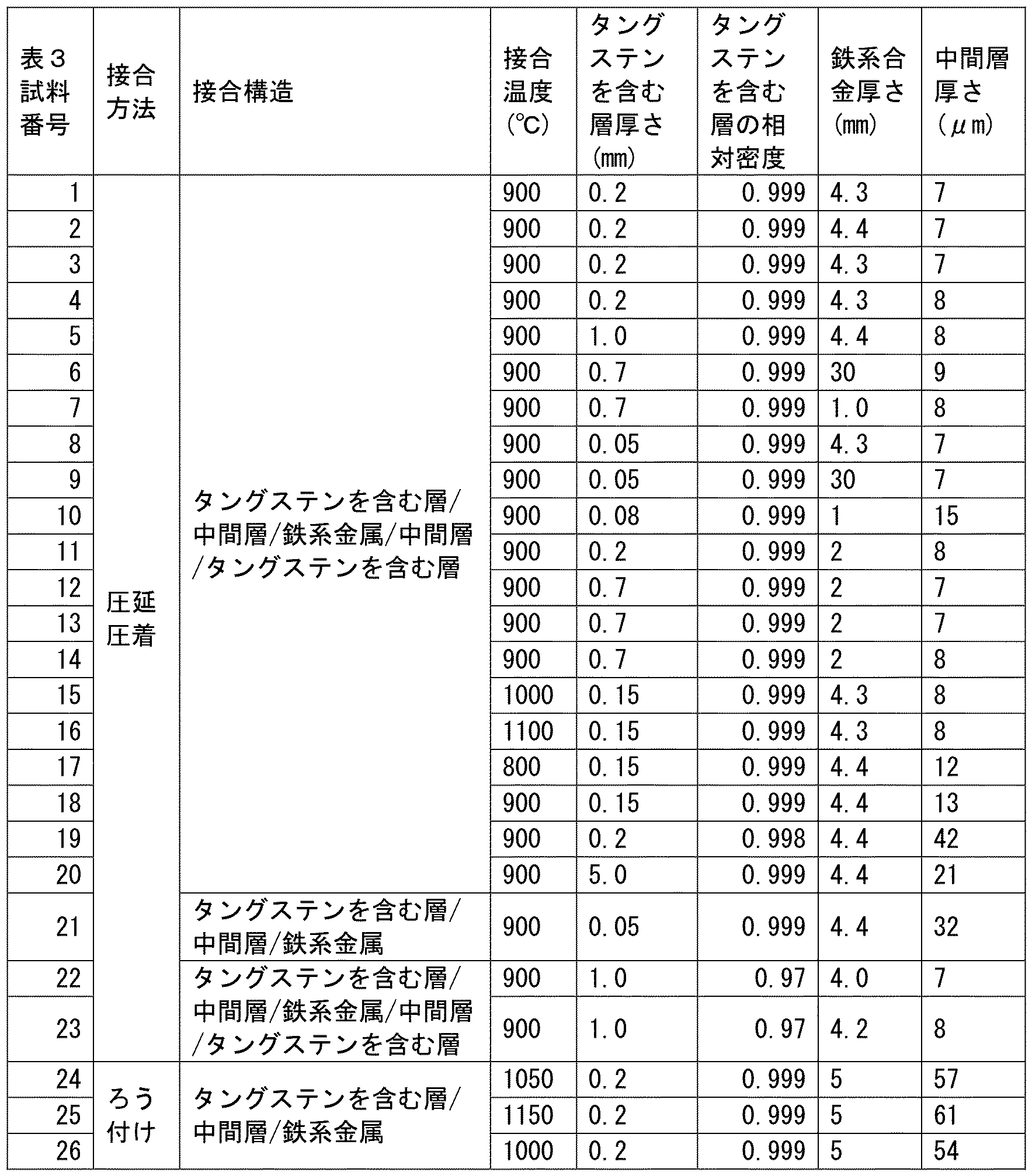
(2)比較例1のサンプルの作成、中間層の厚み評価
比較例として、試料番号24における、ろう付けによるタングステン-鉄系合金接合品を製作し、同様に電子線マイクロアナライザーを用いて断面評価を行った。
比較例として、試料番号24における、ろう付けによるタングステン-鉄系合金接合品を製作し、同様に電子線マイクロアナライザーを用いて断面評価を行った。
ろう付けは、T0.2mm×B100mm×L100mmのタングステン圧延材と、T5mm×B100mm×L100mmのSUS316L板材(鋼材)を、市販のNi系ろう材であるBNi-2(クロム7質量%、ホウ素3質量%、シリコン4.5質量%、鉄3質量%、炭素0.05質量%、残部ニッケル)でろう付けすることで製作した。その原材料を表2に示す。
タングステン圧延材とSUS316L板の表面を#80の耐水ペーパーで研磨した後に、タングステン圧延材/BNi-2/SUS316L板材の順に積層した。接合工程は、積層した状態で上部に9.8Nの荷重をかけた状態で真空中にて加熱し、ろう材の液相出現温度よりも十分高い1050℃で保持したのち、炉冷した。
接合したサンプルは切り出した後、断面を耐水ペーパー#500による粗研磨、ダイヤモンド懸濁液を用いたバフ研磨を行い鏡面とした後、電子線マイクロアナライザー(日本電子(株)製 JXA-8200)を用いて試料番号1と同じ評価を行った。
その結果、タングステンを含む層の厚さが0.2mm、鉄系金属層の厚さが5mmであった。中間層からろう材成分の被接合材中への拡散が見られ、分厚く分布しており57μmの厚さであった。このことから、実施例においては、従来技術よりも薄く均一な中間層を有する接合材を得ることができると認められた。
比較例として試料番号25および26についても同様の加工を行った。それらの結果を表2に示す。BNi-5の組成は、クロム19質量%、シリコン10質量%、残部ニッケルである。BNi-7の組成は、クロム13質量%、リン10質量%、残部ニッケルである。試料番号26は、試料番号25と同様のろう付けによる製作で、ろう材の種類を変えた例である。
(3)タングステンを含む層の密度の評価
得られた試料番号1から26のサンプルの鉄系金属層の厚さ分を平面研削盤で研磨除去した後、電解研磨を行って中間層を除去し、タングステンを含む層のみを取り出した。取り出したタングステンを含む層を、JIS Z 8807(2012)に基づき、液中ひょう量法で密度を測定した。
得られた試料番号1から26のサンプルの鉄系金属層の厚さ分を平面研削盤で研磨除去した後、電解研磨を行って中間層を除去し、タングステンを含む層のみを取り出した。取り出したタングステンを含む層を、JIS Z 8807(2012)に基づき、液中ひょう量法で密度を測定した。
測定にあたっては、空気中で測定したタングステンを含む層の質量と、水中で測定したタングステンの質量を測定し、これを基にタングステンを含む層の密度を求めた。測定した密度をタングステンを含む層の理論密度で除した値をタングステンを含む層の相対密度とした。
測定の結果、試料番号1は99.9%の相対密度であり、タングステンを含む層は十分緻密であることを確認した。試料番号2から26のサンプルについても、97%以上の相対密度を有していることを確認した。
(4)密着度評価
試料番号1に関して、得られたサンプルの密着度をX線CTにより評価した。マイクロフォーカスX線CT装置(島津製作所製 inspeXio SMX-225CT FPD HR)にて評価した。管電圧を200kV、ワーキングディスタンスを10mm、分解能10μmの条件で撮影した。サンプルを撮影したデータから、タングステン直下の直径10μm以上のボイド数をカウントし、1cm2当たりのボイド数を求めた。その結果を表4に示す。
試料番号1に関して、得られたサンプルの密着度をX線CTにより評価した。マイクロフォーカスX線CT装置(島津製作所製 inspeXio SMX-225CT FPD HR)にて評価した。管電圧を200kV、ワーキングディスタンスを10mm、分解能10μmの条件で撮影した。サンプルを撮影したデータから、タングステン直下の直径10μm以上のボイド数をカウントし、1cm2当たりのボイド数を求めた。その結果を表4に示す。

上記評価から、10μm以上のボイドは検出しなかったので、1cm2当たりのボイド数は0個とした。
試料番号24についても試料番号1と同じ評価を行なった。マイクロフォーカスX線CT装置(島津製作所製 inspeXio SMX-225CT FPD HR)、管電圧200kV、ワーキングディスタンス10mm、分解能10μmの条件でサンプルを撮影した。
φ0.1mmの人工欠陥を事前に導入したサンプルでは、X線CT像において欠陥部が黒色、健全部が白色に映ることを確認した。そのため、X線CT像の黒色の箇所を欠陥部とした。測定で得られた画像を、画像解析ソフト(Image-Pro Plus)を用いて、タングステン直下の直径10μm以上のボイド数をカウントし、1cm2当たりのボイド数を算出した。
なお、欠陥の直径の定義は、欠陥部の面積を画像から求めて、欠陥形状を円と仮定して、面積から円の直径に換算した値とした。一連の測定の結果、1cm2当たりのボイド数は26個であった。このことから、本開示は、従来技術よりもボイドが少なく、高密着度の接合が可能であると認められた。他の試料においてもボイドの数を同様の方法で調べた。その結果を表4に示す。
(5)接合強度評価
サンプルの接合強度の評価は、せん断強度試験で行った。図2は、接合強度を評価する方法を説明するための、治具および治具に固定された複合材料の断面図である。
サンプルの接合強度の評価は、せん断強度試験で行った。図2は、接合強度を評価する方法を説明するための、治具および治具に固定された複合材料の断面図である。
表3における試料番号1-26をB10mm×L1mmの寸法に切り出してせん断試験用の複合材料1の試験片を作製した。その試験片を、表面のタングステンを含む層13の厚さ分だけ治具21から突き出した状態となるように治具21の凹部22にセットした。
タングステンを含む層13に圧子23を当てて、万能試験機(インストロン社製5985型)を用い、試験片が破断するまで矢印24で示す圧縮方向に荷重を加えた。試験片の破断箇所を表4において示す。
破断が「母材破断」である場合には、母材であるタングステンを含む層13中での破壊が起こったことを示す。接合強度としては母材のタングステンを含む層13の強度と同等以上であると認められた。
比較例である試料番号24から26のろう付けにより作製したサンプルでも同様の評価を行った結果、タングステン直下の接合界面で破断した。これにより、試料番号24から26では中間層12による接合界面が破壊しやすく、接合強度が不足していることが分かる。
図3は、耐熱性を評価する方法を説明するための、固定台および固定台に固定された複合材料の断面図である。耐熱性を評価するため図3の様に、固定台32上に固定治具31を用いて複合材料1を固定した。1200℃の窒素炉で15分間加熱したところ試料番号24-26の物には中間層の溶融によるズレが観られ本来の形状が維持できておらず試料番号1から23に関しては1200℃の温度では耐熱性が高い事が認められた。
従来から用いられる鉄系合金(鉄、鋼、ステンレス鋼等)では、放射線の遮蔽性、高温の機械的特性、耐水素脆化性などが求められる装置の構造材には適さない場合がある。これらの構造材に関して、タングステンであれば、高密度、高融点、水素脆化しない特性を有するため、これらの構造材に適する可能性がある。
ただし、タングステンは難加工性のため、単独では構造材に適用しがたく、特に構造材の施工に求められる溶接性はで前記鉄系合金に劣るため、単独での構造材への適用は難しい。このため、タングステンと鉄系合金とをろう付けで複合化して用いられる場合があった。しかし、ろう付けなど従来技術による複合化では、タングステンや鉄系合金よりも、はるかに低融点の接合層が存在することにより、タングステンの耐熱性を活かしきれない課題があった。さらに、接合層にボイドまたは脆弱な反応層が残留することで、機械的特性、特に強度が低い課題があった。タングステンと鉄系合金との間に、接合層として両者よりも強度が低い、銅クロム合金または銅ベリリウム合金などの銅合金を介した複合化の例もある。しかし、これら銅合金の融点は鉄系合金よりもはるかに低く、耐熱性と接合層の強度に課題があった。
本開示の複合材料は、これらの課題を解決すべく、高強度で産業上広く用いられる鉄系合金と高密度、高融点、水素脆化しない特性を有するタングステンとの複合化において、耐熱性を有し、かつ接合欠陥が少ない中間層により、耐熱性と高強度とを実現するものである。
今回開示された実施の形態および実施例はすべての点で例示であって制限的なものではないと考えられるべきである。本発明の範囲は上記した説明ではなくて請求の範囲によって示され、請求の範囲と均等の意味および範囲内でのすべての変更が含まれることが意図される。
1 複合材料、11 鉄系合金層、12 中間層、13 タングステンを含む層、21 治具、22 凹部、23 圧子、31 固定治具、32 固定台。
Claims (4)
- 鉄系合金層と、
前記鉄系合金層の上に設けられた中間層と、
前記中間層の上に設けられたタングステンを含む層とを備え、
前記中間層は、
純ニッケルからなるか、または、
銅、コバルトおよび鉄からなる群より選ばれた少なくとも一種を合計で0質量%を超え71質量%以下含み、ニッケルを29質量%以上100質量%未満含む合金からなる、複合材料。 - 前記中間層の厚みが50μm以下である、請求項1に記載の複合材料。
- 前記タングステンを含む層の相対密度が97%以上である、請求項1から2のいずれか1項に記載の複合材料。
- 前記鉄系合金層と、前記タングステンを含む層との間において直径10μm以上のボイドの数が1cm2あたり10個以下である、請求項1から3のいずれか1項に記載の複合材料。
Priority Applications (3)
| Application Number | Priority Date | Filing Date | Title |
|---|---|---|---|
| CN202180023022.8A CN115335187B (zh) | 2020-10-26 | 2021-10-12 | 复合材料 |
| US17/800,422 US12415338B2 (en) | 2020-10-26 | 2021-10-12 | Composite material |
| EP21885885.0A EP4234146A4 (en) | 2020-10-26 | 2021-10-12 | COMPOSITE MATERIAL |
Applications Claiming Priority (2)
| Application Number | Priority Date | Filing Date | Title |
|---|---|---|---|
| JP2020-178511 | 2020-10-26 | ||
| JP2020178511A JP7475258B2 (ja) | 2020-10-26 | 2020-10-26 | 複合材料 |
Publications (1)
| Publication Number | Publication Date |
|---|---|
| WO2022091766A1 true WO2022091766A1 (ja) | 2022-05-05 |
Family
ID=81382460
Family Applications (1)
| Application Number | Title | Priority Date | Filing Date |
|---|---|---|---|
| PCT/JP2021/037683 Ceased WO2022091766A1 (ja) | 2020-10-26 | 2021-10-12 | 複合材料 |
Country Status (5)
| Country | Link |
|---|---|
| US (1) | US12415338B2 (ja) |
| EP (1) | EP4234146A4 (ja) |
| JP (2) | JP7475258B2 (ja) |
| CN (1) | CN115335187B (ja) |
| WO (1) | WO2022091766A1 (ja) |
Families Citing this family (2)
| Publication number | Priority date | Publication date | Assignee | Title |
|---|---|---|---|---|
| JP7475258B2 (ja) | 2020-10-26 | 2024-04-26 | 株式会社アライドマテリアル | 複合材料 |
| JP2023174210A (ja) * | 2022-05-27 | 2023-12-07 | パナソニックIpマネジメント株式会社 | 水素透過フィルタ |
Citations (6)
| Publication number | Priority date | Publication date | Assignee | Title |
|---|---|---|---|---|
| JP2000246549A (ja) | 1999-02-25 | 2000-09-12 | Toshiba Corp | 異種金属材料の接合構造及び接合方法 |
| CN102658443A (zh) * | 2012-05-22 | 2012-09-12 | 江苏科技大学 | 一种钨铜合金与不锈钢钎焊用钎料及钎焊工艺 |
| CN107225249A (zh) * | 2017-06-23 | 2017-10-03 | 中南大学 | 一种基于钨表面梯度合金化的钨/钢扩散连接方法 |
| CN109396631A (zh) * | 2018-11-14 | 2019-03-01 | 中国工程物理研究院材料研究所 | 一种钨/过渡层/不锈钢的热等静压扩散连接方法 |
| CN109454321A (zh) * | 2018-11-16 | 2019-03-12 | 中南大学 | 一种钨/钢圆筒结构件的热等静压扩散连接方法 |
| JP2020178511A (ja) | 2019-04-22 | 2020-10-29 | トヨタ自動車株式会社 | 回転電機ロータの製造方法 |
Family Cites Families (14)
| Publication number | Priority date | Publication date | Assignee | Title |
|---|---|---|---|---|
| US3436806A (en) * | 1967-01-26 | 1969-04-08 | North American Rockwell | Method of forming an aluminum-ferrous tubular transition joint |
| CN1280062C (zh) | 2002-11-26 | 2006-10-18 | 大连铁道学院 | WC-Co硬质合金与钢钨极氩弧焊焊接材料及生产工艺 |
| GB0422608D0 (en) * | 2004-10-12 | 2004-11-10 | Hardide Ltd | Alloyed tungsten produced by chemical vapour deposition |
| CN102000895B (zh) * | 2010-09-29 | 2012-08-01 | 北京科技大学 | 一种钨/低活化钢的真空电子束钎焊连接方法 |
| CN104858570B (zh) * | 2015-03-20 | 2017-01-18 | 江苏科技大学 | 钎焊钨铜合金与不锈钢的高温锆基钎料及制备和钎焊方法 |
| US10686159B2 (en) * | 2015-06-26 | 2020-06-16 | Universal Display Corporation | OLED devices having improved efficiency |
| CN105216394B (zh) * | 2015-10-30 | 2018-02-09 | 中南大学 | 一种基于高温应用的钨/钢复合材料及其制备方法 |
| CN105346161B (zh) * | 2015-10-30 | 2017-07-25 | 中南大学 | 一种钨/过渡层/钢复合材料及其低温低压活性扩散连接的制备方法 |
| CN105499816A (zh) | 2016-02-02 | 2016-04-20 | 中国科学院等离子体物理研究所 | 一种适用于聚变堆第一壁部件钨和钢连接的制造工艺 |
| CN105965176B (zh) | 2016-07-20 | 2018-02-23 | 江苏科技大学 | 用于钎焊钨铜合金与不锈钢的Ni基急冷钎料及钎焊工艺 |
| CN109604802A (zh) | 2019-01-03 | 2019-04-12 | 中国兵器工业第五九研究所 | 钨或钨合金与钢的连接方法、型材的连接方法以及型材接头 |
| CN110303236A (zh) | 2019-08-02 | 2019-10-08 | 中国兵器工业第五九研究所 | 一种用于钨或钨合金与高强度钢的热等静压扩散连接方法 |
| CA3180909A1 (en) * | 2020-05-05 | 2021-11-11 | Nigel Scotchmer | Welded surface coating using electro-spark discharge process |
| JP7475258B2 (ja) | 2020-10-26 | 2024-04-26 | 株式会社アライドマテリアル | 複合材料 |
-
2020
- 2020-10-26 JP JP2020178511A patent/JP7475258B2/ja active Active
-
2021
- 2021-10-12 US US17/800,422 patent/US12415338B2/en active Active
- 2021-10-12 CN CN202180023022.8A patent/CN115335187B/zh active Active
- 2021-10-12 EP EP21885885.0A patent/EP4234146A4/en active Pending
- 2021-10-12 WO PCT/JP2021/037683 patent/WO2022091766A1/ja not_active Ceased
-
2022
- 2022-09-22 JP JP2022151292A patent/JP2022174303A/ja not_active Withdrawn
Patent Citations (6)
| Publication number | Priority date | Publication date | Assignee | Title |
|---|---|---|---|---|
| JP2000246549A (ja) | 1999-02-25 | 2000-09-12 | Toshiba Corp | 異種金属材料の接合構造及び接合方法 |
| CN102658443A (zh) * | 2012-05-22 | 2012-09-12 | 江苏科技大学 | 一种钨铜合金与不锈钢钎焊用钎料及钎焊工艺 |
| CN107225249A (zh) * | 2017-06-23 | 2017-10-03 | 中南大学 | 一种基于钨表面梯度合金化的钨/钢扩散连接方法 |
| CN109396631A (zh) * | 2018-11-14 | 2019-03-01 | 中国工程物理研究院材料研究所 | 一种钨/过渡层/不锈钢的热等静压扩散连接方法 |
| CN109454321A (zh) * | 2018-11-16 | 2019-03-12 | 中南大学 | 一种钨/钢圆筒结构件的热等静压扩散连接方法 |
| JP2020178511A (ja) | 2019-04-22 | 2020-10-29 | トヨタ自動車株式会社 | 回転電機ロータの製造方法 |
Non-Patent Citations (1)
| Title |
|---|
| See also references of EP4234146A4 |
Also Published As
| Publication number | Publication date |
|---|---|
| JP2022069712A (ja) | 2022-05-12 |
| EP4234146A4 (en) | 2024-12-25 |
| US20230086909A1 (en) | 2023-03-23 |
| US12415338B2 (en) | 2025-09-16 |
| JP2022174303A (ja) | 2022-11-22 |
| CN115335187A (zh) | 2022-11-11 |
| JP7475258B2 (ja) | 2024-04-26 |
| EP4234146A1 (en) | 2023-08-30 |
| CN115335187B (zh) | 2024-04-12 |
Similar Documents
| Publication | Publication Date | Title |
|---|---|---|
| US20040134966A1 (en) | Method of producing Ti brazing strips or foils and the resulting brazing strips or foils | |
| WO2022091766A1 (ja) | 複合材料 | |
| EP3705216A1 (en) | Cemented carbide composite material, method for producing same, and cemented carbide tool | |
| WO2012086490A1 (ja) | 回転ツール | |
| CN119973336A (zh) | 用于gh5188瞬时液相扩散连接的高熵合金中间层及其连接方法 | |
| TWI627285B (zh) | Titanium composite and titanium for hot rolling | |
| JP6863332B2 (ja) | クラッド鋼板の製造方法およびクラッド鋼板の製造設備 | |
| EP4450659A1 (en) | Stainless steel powder, stainless steel member, and stainless steel member manufacturing method | |
| Gan et al. | Strengthening electron beam welded joints of AlCoCrFeNi2. 1 eutectic high entropy alloy and 304 stainless steel via constructing cellular heterogeneous dual-phase microstructure | |
| JP2007035336A (ja) | 蒸着マスク用金属製フレームの製造方法 | |
| JP6137423B1 (ja) | チタン複合材および熱間圧延用チタン材 | |
| US20240227353A1 (en) | Composite material | |
| JP3798219B2 (ja) | 鉄基合金部材同士の接合体及び接合方法 | |
| EP4144879A1 (en) | Tungsten material | |
| TW201716231A (zh) | 熱軋用鈦材 | |
| JP6848991B2 (ja) | 熱間圧延用チタン材 | |
| US20150258627A1 (en) | Layer composite | |
| TW201715051A (zh) | 熱軋用鈦材 | |
| JP6690288B2 (ja) | チタン内包構造体およびチタン複層材の製造方法 | |
| JP5354202B2 (ja) | チタンクラッド鋼刃物及びその製造方法 | |
| TW202521727A (zh) | 濺鍍靶組裝體及膜 | |
| JP4562569B2 (ja) | インバー合金と黄銅の複合構造体及びその製造方法 | |
| TW202523883A (zh) | 濺鍍靶組裝體及膜 | |
| JP6039004B2 (ja) | 回転ツール | |
| WO2023281862A1 (ja) | 複合材料 |
Legal Events
| Date | Code | Title | Description |
|---|---|---|---|
| 121 | Ep: the epo has been informed by wipo that ep was designated in this application |
Ref document number: 21885885 Country of ref document: EP Kind code of ref document: A1 |
|
| NENP | Non-entry into the national phase |
Ref country code: DE |
|
| ENP | Entry into the national phase |
Ref document number: 2021885885 Country of ref document: EP Effective date: 20230526 |
|
| WWG | Wipo information: grant in national office |
Ref document number: 17800422 Country of ref document: US |