WO2022091949A1 - 状態監視システムおよび状態監視方法 - Google Patents
状態監視システムおよび状態監視方法 Download PDFInfo
- Publication number
- WO2022091949A1 WO2022091949A1 PCT/JP2021/038980 JP2021038980W WO2022091949A1 WO 2022091949 A1 WO2022091949 A1 WO 2022091949A1 JP 2021038980 W JP2021038980 W JP 2021038980W WO 2022091949 A1 WO2022091949 A1 WO 2022091949A1
- Authority
- WO
- WIPO (PCT)
- Prior art keywords
- modeling
- defect
- condition monitoring
- information
- defect state
- Prior art date
- Legal status (The legal status is an assumption and is not a legal conclusion. Google has not performed a legal analysis and makes no representation as to the accuracy of the status listed.)
- Ceased
Links
Images




Classifications
-
- B—PERFORMING OPERATIONS; TRANSPORTING
- B22—CASTING; POWDER METALLURGY
- B22F—WORKING METALLIC POWDER; MANUFACTURE OF ARTICLES FROM METALLIC POWDER; MAKING METALLIC POWDER; APPARATUS OR DEVICES SPECIALLY ADAPTED FOR METALLIC POWDER
- B22F12/00—Apparatus or devices specially adapted for additive manufacturing; Auxiliary means for additive manufacturing; Combinations of additive manufacturing apparatus or devices with other processing apparatus or devices
- B22F12/90—Means for process control, e.g. cameras or sensors
-
- G—PHYSICS
- G01—MEASURING; TESTING
- G01N—INVESTIGATING OR ANALYSING MATERIALS BY DETERMINING THEIR CHEMICAL OR PHYSICAL PROPERTIES
- G01N29/00—Investigating or analysing materials by the use of ultrasonic, sonic or infrasonic waves; Visualisation of the interior of objects by transmitting ultrasonic or sonic waves through the object
- G01N29/14—Investigating or analysing materials by the use of ultrasonic, sonic or infrasonic waves; Visualisation of the interior of objects by transmitting ultrasonic or sonic waves through the object using acoustic emission techniques
-
- B—PERFORMING OPERATIONS; TRANSPORTING
- B22—CASTING; POWDER METALLURGY
- B22F—WORKING METALLIC POWDER; MANUFACTURE OF ARTICLES FROM METALLIC POWDER; MAKING METALLIC POWDER; APPARATUS OR DEVICES SPECIALLY ADAPTED FOR METALLIC POWDER
- B22F10/00—Additive manufacturing of workpieces or articles from metallic powder
- B22F10/80—Data acquisition or data processing
-
- B—PERFORMING OPERATIONS; TRANSPORTING
- B29—WORKING OF PLASTICS; WORKING OF SUBSTANCES IN A PLASTIC STATE IN GENERAL
- B29C—SHAPING OR JOINING OF PLASTICS; SHAPING OF MATERIAL IN A PLASTIC STATE, NOT OTHERWISE PROVIDED FOR; AFTER-TREATMENT OF THE SHAPED PRODUCTS, e.g. REPAIRING
- B29C64/00—Additive manufacturing, i.e. manufacturing of three-dimensional [3D] objects by additive deposition, additive agglomeration or additive layering, e.g. by 3D printing, stereolithography or selective laser sintering
- B29C64/30—Auxiliary operations or equipment
- B29C64/386—Data acquisition or data processing for additive manufacturing
-
- B—PERFORMING OPERATIONS; TRANSPORTING
- B29—WORKING OF PLASTICS; WORKING OF SUBSTANCES IN A PLASTIC STATE IN GENERAL
- B29C—SHAPING OR JOINING OF PLASTICS; SHAPING OF MATERIAL IN A PLASTIC STATE, NOT OTHERWISE PROVIDED FOR; AFTER-TREATMENT OF THE SHAPED PRODUCTS, e.g. REPAIRING
- B29C64/00—Additive manufacturing, i.e. manufacturing of three-dimensional [3D] objects by additive deposition, additive agglomeration or additive layering, e.g. by 3D printing, stereolithography or selective laser sintering
- B29C64/30—Auxiliary operations or equipment
- B29C64/386—Data acquisition or data processing for additive manufacturing
- B29C64/393—Data acquisition or data processing for additive manufacturing for controlling or regulating additive manufacturing processes
-
- B—PERFORMING OPERATIONS; TRANSPORTING
- B33—ADDITIVE MANUFACTURING TECHNOLOGY
- B33Y—ADDITIVE MANUFACTURING, i.e. MANUFACTURING OF THREE-DIMENSIONAL [3D] OBJECTS BY ADDITIVE DEPOSITION, ADDITIVE AGGLOMERATION OR ADDITIVE LAYERING, e.g. BY 3D PRINTING, STEREOLITHOGRAPHY OR SELECTIVE LASER SINTERING
- B33Y50/00—Data acquisition or data processing for additive manufacturing
-
- B—PERFORMING OPERATIONS; TRANSPORTING
- B33—ADDITIVE MANUFACTURING TECHNOLOGY
- B33Y—ADDITIVE MANUFACTURING, i.e. MANUFACTURING OF THREE-DIMENSIONAL [3D] OBJECTS BY ADDITIVE DEPOSITION, ADDITIVE AGGLOMERATION OR ADDITIVE LAYERING, e.g. BY 3D PRINTING, STEREOLITHOGRAPHY OR SELECTIVE LASER SINTERING
- B33Y50/00—Data acquisition or data processing for additive manufacturing
- B33Y50/02—Data acquisition or data processing for additive manufacturing for controlling or regulating additive manufacturing processes
-
- B—PERFORMING OPERATIONS; TRANSPORTING
- B33—ADDITIVE MANUFACTURING TECHNOLOGY
- B33Y—ADDITIVE MANUFACTURING, i.e. MANUFACTURING OF THREE-DIMENSIONAL [3D] OBJECTS BY ADDITIVE DEPOSITION, ADDITIVE AGGLOMERATION OR ADDITIVE LAYERING, e.g. BY 3D PRINTING, STEREOLITHOGRAPHY OR SELECTIVE LASER SINTERING
- B33Y99/00—Subject matter not provided for in other groups of this subclass
-
- B—PERFORMING OPERATIONS; TRANSPORTING
- B22—CASTING; POWDER METALLURGY
- B22F—WORKING METALLIC POWDER; MANUFACTURE OF ARTICLES FROM METALLIC POWDER; MAKING METALLIC POWDER; APPARATUS OR DEVICES SPECIALLY ADAPTED FOR METALLIC POWDER
- B22F10/00—Additive manufacturing of workpieces or articles from metallic powder
- B22F10/20—Direct sintering or melting
- B22F10/28—Powder bed fusion, e.g. selective laser melting [SLM] or electron beam melting [EBM]
-
- B—PERFORMING OPERATIONS; TRANSPORTING
- B22—CASTING; POWDER METALLURGY
- B22F—WORKING METALLIC POWDER; MANUFACTURE OF ARTICLES FROM METALLIC POWDER; MAKING METALLIC POWDER; APPARATUS OR DEVICES SPECIALLY ADAPTED FOR METALLIC POWDER
- B22F10/00—Additive manufacturing of workpieces or articles from metallic powder
- B22F10/80—Data acquisition or data processing
- B22F10/85—Data acquisition or data processing for controlling or regulating additive manufacturing processes
-
- B—PERFORMING OPERATIONS; TRANSPORTING
- B22—CASTING; POWDER METALLURGY
- B22F—WORKING METALLIC POWDER; MANUFACTURE OF ARTICLES FROM METALLIC POWDER; MAKING METALLIC POWDER; APPARATUS OR DEVICES SPECIALLY ADAPTED FOR METALLIC POWDER
- B22F2999/00—Aspects linked to processes or compositions used in powder metallurgy
-
- B—PERFORMING OPERATIONS; TRANSPORTING
- B29—WORKING OF PLASTICS; WORKING OF SUBSTANCES IN A PLASTIC STATE IN GENERAL
- B29C—SHAPING OR JOINING OF PLASTICS; SHAPING OF MATERIAL IN A PLASTIC STATE, NOT OTHERWISE PROVIDED FOR; AFTER-TREATMENT OF THE SHAPED PRODUCTS, e.g. REPAIRING
- B29C64/00—Additive manufacturing, i.e. manufacturing of three-dimensional [3D] objects by additive deposition, additive agglomeration or additive layering, e.g. by 3D printing, stereolithography or selective laser sintering
- B29C64/10—Processes of additive manufacturing
- B29C64/141—Processes of additive manufacturing using only solid materials
- B29C64/153—Processes of additive manufacturing using only solid materials using layers of powder being selectively joined, e.g. by selective laser sintering or melting
-
- B—PERFORMING OPERATIONS; TRANSPORTING
- B33—ADDITIVE MANUFACTURING TECHNOLOGY
- B33Y—ADDITIVE MANUFACTURING, i.e. MANUFACTURING OF THREE-DIMENSIONAL [3D] OBJECTS BY ADDITIVE DEPOSITION, ADDITIVE AGGLOMERATION OR ADDITIVE LAYERING, e.g. BY 3D PRINTING, STEREOLITHOGRAPHY OR SELECTIVE LASER SINTERING
- B33Y10/00—Processes of additive manufacturing
-
- B—PERFORMING OPERATIONS; TRANSPORTING
- B33—ADDITIVE MANUFACTURING TECHNOLOGY
- B33Y—ADDITIVE MANUFACTURING, i.e. MANUFACTURING OF THREE-DIMENSIONAL [3D] OBJECTS BY ADDITIVE DEPOSITION, ADDITIVE AGGLOMERATION OR ADDITIVE LAYERING, e.g. BY 3D PRINTING, STEREOLITHOGRAPHY OR SELECTIVE LASER SINTERING
- B33Y30/00—Apparatus for additive manufacturing; Details thereof or accessories therefor
-
- G—PHYSICS
- G01—MEASURING; TESTING
- G01N—INVESTIGATING OR ANALYSING MATERIALS BY DETERMINING THEIR CHEMICAL OR PHYSICAL PROPERTIES
- G01N2291/00—Indexing codes associated with group G01N29/00
- G01N2291/02—Indexing codes associated with the analysed material
- G01N2291/023—Solids
- G01N2291/0231—Composite or layered materials
-
- G—PHYSICS
- G01—MEASURING; TESTING
- G01N—INVESTIGATING OR ANALYSING MATERIALS BY DETERMINING THEIR CHEMICAL OR PHYSICAL PROPERTIES
- G01N2291/00—Indexing codes associated with group G01N29/00
- G01N2291/02—Indexing codes associated with the analysed material
- G01N2291/028—Material parameters
- G01N2291/0289—Internal structure, e.g. defects, grain size, texture
-
- Y—GENERAL TAGGING OF NEW TECHNOLOGICAL DEVELOPMENTS; GENERAL TAGGING OF CROSS-SECTIONAL TECHNOLOGIES SPANNING OVER SEVERAL SECTIONS OF THE IPC; TECHNICAL SUBJECTS COVERED BY FORMER USPC CROSS-REFERENCE ART COLLECTIONS [XRACs] AND DIGESTS
- Y02—TECHNOLOGIES OR APPLICATIONS FOR MITIGATION OR ADAPTATION AGAINST CLIMATE CHANGE
- Y02P—CLIMATE CHANGE MITIGATION TECHNOLOGIES IN THE PRODUCTION OR PROCESSING OF GOODS
- Y02P10/00—Technologies related to metal processing
- Y02P10/25—Process efficiency
Definitions
- the present invention relates to a condition monitoring system and a condition monitoring method, for example, a technique for monitoring the state of three-dimensional laminated modeling.
- a measured acoustic profile is generated by measuring the acoustic energy generated by the molten pool with a microphone, and the measured acoustic profile is compared with a known reference acoustic profile to obtain defects.
- a method of determining the presence or absence is shown.
- a modeling device such as a 3D printer has been used to manufacture a model having a complicated shape.
- a manufacturing method using such a modeling device is called three-dimensional laminated modeling.
- a model manufactured by three-dimensional laminated modeling may contain defects.
- the modeled body generates a peculiar acoustic signal with the occurrence of defects. Therefore, in the method of Patent Document 1, the sound generated during modeling is monitored by a microphone, and the presence or absence of a defect is determined by whether or not the sound includes an acoustic signal associated with the defect. When this method is used, all the shaped objects including defects will be determined to be defective.
- a modeled body containing defects may be regarded as a non-defective product depending on the degree of defects. Specifically, information such as the number, size, density, position, type (horizontal cracking, vertical cracking, peeling, etc.) of defects, etc., can be determined for determining whether the modeled body is non-defective or defective. It may be desirable to do it comprehensively. For that purpose, a mechanism that can perform quality control of the modeled object with optimum specifications that are neither over-specification nor under-specification, in other words, a mechanism that can perform quality control of the modeled object with high accuracy is required.
- the present invention has been made in view of the above, and one of the objects thereof is to provide a condition monitoring system and a condition monitoring method capable of performing quality control of a modeled body with high accuracy. be.
- the analysis device includes a memory for storing defect database information representing the correlation between the defect state of the model and the acoustic signal, and the amplitude and frequency of the acoustic signal included in the output signal.
- defect database information representing the correlation between the defect state of the model and the acoustic signal, and the amplitude and frequency of the acoustic signal included in the output signal.
- the preparation step to be stored in the memory the detection step of detecting the acoustic signal from the output signal of the acoustic sensor, and the amplitude, frequency, wave number, convergence time, and generation interval of the acoustic signal detected in the detection step.
- the specific step of specifying the defect state of the model as the specified defect state and the model based on the specified defect state It has a determination step for determining the quality of the above.
- FIG. 1A It is a schematic diagram which shows the application example of the condition monitoring system by one Embodiment of this invention. It is a schematic diagram which shows the application example of the condition monitoring system in the post-modeling period following FIG. 1A. It is a schematic diagram which shows the application example different from FIG. 1A of the state monitoring system by one Embodiment of this invention. It is a schematic diagram which shows the application example of the condition monitoring system in the post-modeling period following FIG. 2A. It is a waveform diagram which shows an example of the output signal of the acoustic sensor in FIG. 1A, FIG. 1B, FIG. 2A and FIG. 2B. It is a block diagram which shows the structural example of the main part of the analysis apparatus in FIG. 1A, FIG. 1B, FIG.
- FIG. 2A and FIG. 2B It is a flow diagram which shows an example of the processing content of the state monitoring method using the state monitoring system of FIG. 1A or FIG. 2A. It is a flow chart which shows an example of the processing content of the state monitoring method using the state monitoring system of FIG. 1B or FIG. 2B.
- FIG. 1A is a schematic diagram showing an application example of a condition monitoring system according to an embodiment of the present invention.
- FIG. 1B is a schematic diagram showing an application example of a condition monitoring system in the post-modeling period following FIG. 1A.
- FIG. 1A shows a configuration example of the condition monitoring system 1 during modeling of three-dimensional laminated modeling.
- FIG. 1A shows a modeling device 10a, a modeling control device 11, and an analysis device 12.
- the modeling device 10a is, for example, a three-dimensional laminated modeling device (3D printer) for metals using a powder bed melt-bonding method.
- the energy source 15 irradiates the galvano scanner 16 with an energy beam (for example, laser light).
- the galvano scanner 16 reflects the energy beam from the energy source 15 in the direction of the work stage 17 while changing the reflection angle.
- the work stage 17 is provided with a filling tank 18, a workspace 19, and a recovery tank 20.
- the filling tank 18 is filled with a material powder 42 such as a metal powder, for example.
- the piston 21 exposes the material powder 42 in the filling tank 18 onto the work stage 17.
- the roller (or recorder) 24 spreads the exposed material powder 42 on the work stage 17. As a result, the material powder 42 is spread in the workspace 19. At this time, the piston 22 controls the thickness of the material powder 42 spread in the workspace 19. The recovery tank 20 recovers the surplus material powder 42 in the workspace 19 as the roller (recoater) 24 operates.
- a modeling stage 41 is mounted on the upper part of the piston 22. The modeled body 40 is laminated and modeled on the modeling stage 41 by the powder bed fusion bonding method.
- the following unit steps are repeatedly executed.
- the piston 22 and the roller (recoater) 24 spread the material powder 42 in the workspace 19 with a thickness TN equivalent to several tens of microns, and then the galvano scanner 16 sends an energy beam to the material powder 42.
- the material powder 42 is melt-bonded by irradiation.
- the modeled body 40 is sequentially laminated and modeled on the modeling stage 41 with the thickness TN as a unit. Further, the shape of the model 40 is determined by controlling the orientation of the galvano scanner 16 based on the CAD data.
- the modeling control device 11 controls each part of the modeling device 10a so that such a modeling operation is performed.
- a defect occurs in the modeled body 40 during modeling, a peculiar sound is generated from the defective portion.
- Typical examples of such defects include solidification cracks and the like that occur in the process of solidification after the material powder 42 is melted due to irradiation with an energy beam. Therefore, in order to capture this sound, in this example, a single or a plurality (plural) acoustic sensors 23 are attached to the lower part of the piston 22.
- the acoustic sensor 23 is an AE (Acoustic Emission) sensor including, for example, a piezoelectric element such as PZT (lead zirconate titanate).
- the sound generated from the modeling body 40 propagates to the acoustic sensor 23 via, for example, the modeling stage 41 and the piston 22 which are metal members.
- the acoustic sensor 23 detects the sound generated from the model 40.
- the output signal of the acoustic sensor 23 includes an acoustic signal (AE signal) which is a sound peculiar to a defect.
- the analysis device 12 analyzes the defect of the modeled body 40 generated during the modeling based on this acoustic signal.
- Such an acoustic sensor 23 and an analysis device 12 constitute a condition monitoring system 1.
- FIG. 1B shows the state after the modeling of the modeled body 40 is completed by FIG. 1A.
- the modeling body 40 is removed from the modeling device 10a together with the modeling stage 41.
- the modeling body 40 and the modeling stage 41 being modeled are in a high temperature state due to the irradiation of the energy beam. Therefore, it is desirable to cool the model 40 and the model stage 41 during the cooling period after modeling (for example, 1 hour or more). During this cooling period, the model 40 may have defects such as delayed cracking due to residual stress.
- the model 40 may have defects due to changes in the material structure. For example, hydrogen or the like mixed in the material during modeling may diffuse to the grain boundaries, causing hydrogen embrittlement and cracking. Therefore, in the example of FIG. 1B, the acoustic sensor 23 is mounted on the modeling stage 41 after modeling.
- the analysis device 12 analyzes defects in the modeled body 40 that occur in the post-modeling period, which is a predetermined period after modeling, based on the acoustic signal (AE signal) included in the output signal of the acoustic sensor 23.
- the post-modeling period corresponds to the above-mentioned cooling period and post-cooling period. Then, after a period after the modeling, the modeling body 40 is separated from the modeling stage 41.
- the acoustic sensor 23 be mounted at a position close to the model 40. From this point of view, the acoustic sensor 23 may be mounted on the model stage 41 in FIG. 1A as in the case of FIG. 1B. good. However, from the viewpoint of device protection due to a high temperature state, the acoustic sensor 23 may be mounted on the piston 22 as shown in FIG. 1A. Further, since the mounting position of the acoustic sensor 23 is different between FIGS. 1A and 1B, the conditions of the acoustic signal input to the analysis device 12 (for example, the reference amplitude value and the like) may be different. Therefore, from the viewpoint of matching the input conditions of the acoustic signal, in FIG. 1B, a member corresponding to the piston 22 of FIG. 1A may be inserted between the modeling stage 41 and the acoustic sensor 23.
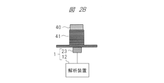
- FIG. 2A is a schematic diagram showing an application example different from that of FIG. 1A of the condition monitoring system according to the embodiment of the present invention.
- FIG. 2B is a schematic diagram showing an application example of a condition monitoring system in the post-modeling period following FIG. 2A.
- FIG. 2A shows a configuration example of the condition monitoring system 1 during modeling of three-dimensional laminated modeling.
- FIG. 2A shows a modeling device 10b, a modeling control device 11, and an analysis device 12.
- the modeling device 10b is, for example, a three-dimensional laminated modeling device (3D printer) for metals using a directed energy deposition method, unlike FIG. 1A.
- the modeling stage 41 is mounted on the work stage 32.
- the modeling head 30 is provided with an energy nozzle 31, and while injecting a material powder 42 such as metal powder, an energy beam (for example, laser light) from the energy nozzle 31 is directed toward the modeling stage 41 while changing the direction. Irradiate.
- the direction of the modeling head 30 is controlled based on the CAD data.
- the directed energy deposition method is a method of irradiating an energy beam while injecting the material powder 42 to deposit the molten metal.
- the modeling control device 11 controls each part of the modeling device 10b so that such a modeling operation is performed. Further, in this example, a single or a plurality of (singular in this example) acoustic sensors 23 are attached to the work stage 32.
- the analysis device 12 analyzes the defect of the modeled body 40 generated during modeling based on the acoustic signal included in the output signal of the acoustic sensor 23. Such an acoustic sensor 23 and an analysis device 12 constitute a condition monitoring system 1.
- FIG. 2B shows the state after the modeling of the modeled body 40 is completed by FIG. 2A.
- the modeling body 40 is removed from the modeling device 10b together with the modeling stage 41.
- a post-modeling period (cooling period and post-cooling period) is provided as in the case of FIG. 1B.
- the acoustic sensor 23 is mounted on the modeling stage 41.
- the analysis device 12 analyzes the defect of the modeled body 40 generated after modeling based on the acoustic signal included in the output signal of the acoustic sensor 23. After that, the model 40 is separated from the model stage 41.
- the mounting position of the acoustic sensor 23 can be appropriately changed as in the case of FIGS. 1A and 1B.
- the energy beam is not limited to the laser beam, and may be, for example, an electron beam or the like.
- the analysis device 12 in FIGS. 1A and 2A analyzes defects in the modeled body 40 that occur during and after modeling based on the acoustic signal included in the output signal of the acoustic sensor 23.
- FIG. 3 is a waveform diagram showing an example of the output signal of the acoustic sensor in FIGS. 1A, 1B, 2A and 2B.
- FIG. 3 shows output signals OT1 and OT2 of the acoustic sensor 23 obtained for different shaped objects [1] and [2], respectively. Further, FIG. 3 shows the output signals OT1 and OT2 obtained in the modeling period T1 and the modeling period T2.
- the modeling period T1 is a period during modeling of the modeling body 40 as described in FIG. 1A or FIG. 2A.
- the post-modeling period T2 is a predetermined period after the modeling of the modeled body 40 is completed, and corresponds to the above-mentioned cooling period and post-cooling period.
- the output signal OT1 obtained from the modeled body [1] contains a large amount of acoustic signal AES in the modeling period T1 and hardly contains the acoustic signal AES in the post-modeling period T2.
- the output signal OT2 obtained from the modeled body [2] includes a large amount of acoustic signal AES in the post-modeling period T2, and hardly includes the acoustic signal AES in the modeling period T1.
- the acoustic signal AES is a peculiar sound generated by a defect of the model 40, and each acoustic signal AES is also referred to as a sudden AE signal.
- the pattern of generation of the acoustic signal AES from the model 40 may be appropriately different depending on the material, shape, and the like of the model 40. Further, one acoustic signal AES in the modeling period T1 often represents one defect.
- the waveform shape of each acoustic signal AES can be represented by parameters such as amplitude AM, frequency FQ, wave number WN, convergence time TC, and generation interval TB.
- the amplitude AM is, for example, the maximum value among the amplitude values of each waveform in a waveform having a plurality of cycles included in the acoustic signal AES.
- the wave number WN is the number of multiple cycles included in this acoustic signal AES.
- the convergence time TC is the time from when the amplitude of each waveform becomes larger than a predetermined lower limit value (for example, a value for eliminating steady noise) to when it becomes smaller than a predetermined lower limit value.
- the frequency FQ is the frequency of the acoustic signal AES, and can also be calculated by the wave number WN / convergence time TC.
- the waveform shape of such an acoustic signal AES may be appropriately different depending on the type of defect (horizontal crack, vertical crack, peeling, etc.), the degree (magnitude) of the defect, and the like.
- the degree (magnitude) of the defect is reflected in the amplitude AM.
- the generation interval TB of the acoustic signal AES may differ depending on, for example, the type of defect.
- the generation interval TB of the acoustic signal AES represents, here, the time interval between the time when the acoustic signal AES of interest is generated and the time when the previous acoustic signal AES is generated.
- FIG. 4 is a block diagram showing a configuration example of a main part of the analysis device in FIGS. 1A, 1B, 2A and 2B.
- the analysis device 12 shown in FIG. 4 includes a signal processing circuit 50, a defect information analyzer 51, a memory 52, and a notification device 53.
- the signal processing circuit 50 receives the output signal OT of the acoustic sensor 23 and detects the acoustic signal AES included in the output signal OT.
- the signal processing circuit 50 detects waveform shape parameters such as amplitude AM, frequency FQ, wave number WN, convergence time TC, and generation interval TB with respect to the detected acoustic signal AES, and an acoustic parameter signal including each parameter.
- the signal processing circuit 50 encloses, for example, a filter that removes noise from the received acoustic signal AES, an amplifier that amplifies the filtered signal, a counter that detects the wave number WN from the amplified signal, and an amplified signal. It is equipped with a detector for line detection.
- the memory 52 is, for example, a flash memory or a non-volatile memory such as a hard disk drive, and stores defect database information 61 (abbreviated as defect DB information 61) and determination criterion information 62.
- the defect DB information 61 represents the correlation between the defect state DS of the model 40 and the acoustic signal AES (specifically, the acoustic parameter signal APS).
- the defect state DS represents the type of defect (horizontal crack, vertical crack, peeling, etc.) and the degree of defect (for example, graded size, etc.). That is, the defect DB information 61 represents the correlation between the waveform shape of the acoustic signal AES and the type and degree of the defect.
- the user creates the defect DB information 61 by deriving this correlation by physical analysis of the defect or the like, and registers it in the memory 52 in advance.
- the defect information analyzer 51 is typically implemented by program processing using a processor (CPU (Central Processing Unit)) included in a microcontroller, a computer, or the like.
- a processor Central Processing Unit
- the mounting form is not limited to this, and a part or all of the defect information analyzer 51 can be mounted by FPGA (Field Programmable Gate Array), ASIC (Application Specific Integrated Circuit), or the like.
- the defect information analyzer 51 includes a DB reference unit 55, a defect state information creation unit 56, an internal memory 57, a determination unit 58, and a timer 59.
- the DB reference unit 55 identifies the defect state DS of the model 40 as the specified defect states DSa and DSb by referring to the defect DB information 61 using the acoustic parameter signal APS.
- the DB reference unit 55 uses at least one of the parameters of the amplitude AM, the frequency FQ, the wave number WN, the convergence time TC, and the generation interval TB of the acoustic signal AES based on the acoustic parameter signal APS to be the defect DB.
- the defect state DS is specified by referring to the information 61.
- the defect state DS may have a correlation with some parameters instead of all the parameters (AM, FQ, WN, TC, TB) included in the acoustic parameter signal APS.
- the defect DB information 61 for example, the correlation between the numerical range of some of the parameters and the defect state DS is determined, and the remaining parameters are defined in Don't Care.
- the DB reference unit 55 outputs the specified defect state DSa specified in the modeling period T1 and the specified defect state DSb specified in the post-modeling period T2 to the defect state information creating unit 56.
- the defect state information creation unit 56 creates defect state information DSSa based on the information of the modeling time tm in the modeling period T1 of FIG. 3, and stores it in the internal memory 57.
- the defect state information DSSa includes one or more correspondences between the specified defect state DSa specified in the modeling period T1 and the modeling time tm. That is, the defect state information DSSa includes, for example, information that a defect of the defect state DSa1 occurs at a certain modeling time tm1 and a defect of the defect state DSa2 occurs at another modeling time tm2.
- the information of the modeling time tm is obtained from the modeling control device 11.
- the modeling control device 11 sequentially grasps which position of the modeling body 40 is to be modeled at which modeling time. Therefore, the information of the modeling time tm is equivalent to the information of the modeling position.
- the defect state information DSSa substantially includes information such as what kind of defect has occurred at which modeling position of the modeled body 40.
- the defect state information creation unit 56 creates the defect state information DSSb based on the information of the detection time td of the acoustic signal AES in the post-modeling period T2 of FIG. 3, and stores it in the internal memory 57.
- the defect state information DSSb includes a single or a plurality of correspondences between the identified defect state DSb specified in the post-modeling period T2 and the detection time td. That is, the defect state information DSSb includes, for example, information that a defect in the defect state DSb1 has occurred at a certain detection time td1.
- the information of the detection time td is obtained from the timer 59.
- the timer 59 starts the timer operation, for example, at the start of the post-modeling period T2.
- the information on the modeling position is unknown.
- the determination unit 58 determines the quality of the modeled body 40 based on the defect state information DSSa including the identified defect state DSa and the determination reference information 62 in the memory 52 for the modeling period T1. Further, the determination unit 58 determines the quality of the modeled body 40 based on the defect state information DSSb including the specified defect state DSb and the determination reference information 62 in the memory 52 for the post-modeling period T2.
- the determination unit 58 determines, for example, the quality or quality grade of the model 40.
- the determination standard information 62 includes a determination standard such as a defective product when a number of defects having a certain specified defect state DSa occur for the modeling period T1 and a predetermined modeling time tm. Judgment criteria such as defective products if defects occur at (that is, modeling position) are appropriately determined.
- a judgment standard such as a defective product when a number of defects having a certain specified defect state DSb occur or more is appropriately defined for the post-modeling period T2.
- a determination criterion is appropriately determined for the post-modeling period T2, such as a defective product if a number of defects having a certain specified defect state DSb occur within a certain period.
- the defect having a predetermined specified defect state DSa and the defect having a predetermined specified defect state DSb are targeted for the modeling period T1 and the modeling period T2.
- Judgment criteria such as defective products are set as appropriate when the total value is more than one.
- the determination unit 58 determines the quality of the modeled body 40 by collating the determination standard information 62 with the defect state information DSSa and DSSb. Further, when determining the quality grade of the modeled body 40, such determination criteria may be subdivided and determined.
- the quality of the model 40 is determined not only by the presence or absence of defects as in Patent Document 1, but also by the size and type of defects (horizontal) obtained from the specified defect states DSa and DSb for each application of the model 40. It is desirable to perform it based on cracks, vertical cracks, peeling, etc.). For example, depending on the use of the modeled body 40, if it is a predetermined type of small defect, it may be regarded as a non-defective product.
- the quality of the model 40 is determined by integrating the information such as the number, size, density, position, and type of defects obtained from the defect state information DSSa and DSSb.
- the quality of the model 40 is determined by integrating the information such as the number, size, density, position, and type of defects obtained from the defect state information DSSa and DSSb.
- the modeling position for example, the modeling position where stress is easily applied, it may be better to consider even a small defect to be a defective product.
- the determination unit 58 outputs the quality determination result QR determined in this way to the notification device 53.
- the notification device 53 is, for example, a display or the like.
- the notification device 53 notifies the user of the quality determination result QR of the modeled body 40. Further, the notification device 53 may notify the user of the defect state information DSSa and DSSb. In this case, the user can grasp the tendency of occurrence of defects based on the defect state information DSSa and DSSb, and appropriately reflect them in, for example, improving the quality of the three-dimensional laminated modeling process.
- FIG. 5 is a flow chart showing an example of the processing content of the condition monitoring method using the condition monitoring system of FIG. 1A or FIG. 2A.
- step S100 preparation step
- the user stores in advance the defect DB information 61 representing the correlation between the defect state DS of the model 40 and the acoustic signal AES in the memory 52.
- step S101 the condition monitoring system 1 waits for the start of the modeling period T1 shown in FIG.
- the condition monitoring system 1 repeatedly executes the processes of steps S102 to S106 until the modeling period T1 ends (step S107).
- step S102 the analysis device 12 (specifically, the signal processing circuit 50) monitors the output signal OT of the acoustic sensor 23.
- step S103 detection step
- the signal processing circuit 50 detects the acoustic signal AES from the output signal OT of the acoustic sensor 23.
- step S104 the signal processing circuit 50 detects the parameters of the amplitude AM, the frequency FQ, the wave number WN, the convergence time TC, and the generation interval TB with respect to the detected acoustic signal AES.
- step S105 the analyzer 12 (specifically, the defect information analyzer 51) refers to the defect DB information 61 using at least one of the parameters detected in step S104.
- the defective state DS is specified as the identified defective state DSa.
- step S106 the defect information analyzer 51 creates defect state information DSSa in which the identified defect state DSa identified in step S105 and the modeling time tm from the modeling control device 11 are associated with each other. Is stored in the internal memory 57.
- step S107 the modeling period T1 ends in step S107.
- step S108 determination step
- the defect information analyzer 51 determines the quality of the completed model 40 based on the defect state information DSSa created and stored in step S106.
- step S108 the defect information analyzer 51 recognizes the type and degree of defects and the number of defects generated based on the identified defect state DSa included in the defect state information DSSa, for example. Then, by collating with the determination standard information 62, the quality, grade, and the like of the model 40 are determined. Alternatively, the defect information analyzer 51 recognizes what kind of defect has occurred at which modeling position in the modeled body 40 based on the identified defect state DSa included in the defect state information DSSa and the modeling time tm. By collating with the determination standard information 62, the quality, grade, and the like of the model 40 are determined.
- the analysis device 12 may notify the notification device 53 of the quality determination result QR in step S108 and the defect state information DSSa created in step S106.
- step S106 the modeling time tm is obtained from the modeling control device 11, but instead, the detection time td of the timer 59 in FIG. 4 may be used. In this case, the timer 59 may start the timer operation by receiving a trigger for starting the modeling from the modeling control device 11.
- FIG. 6 is a flow chart showing an example of the processing content of the condition monitoring method using the condition monitoring system of FIG. 1B or FIG. 2B.
- step S200 preparation step
- the user stores in advance the defect DB information 61 representing the correlation between the defect state DS of the model 40 and the acoustic signal AES in the memory 52.
- step S201 the condition monitoring system 1 waits for the start of the post-modeling period T2 shown in FIG.
- the condition monitoring system 1 resets the detection time td of the timer 59 and starts the timer 59 (step S202). After that, the condition monitoring system 1 repeatedly executes the processes of steps S203 to S207 until the post-modeling period T2 ends (step S208).
- steps S203 to S207 is the same as the processing of S102 to S106 shown in FIG. However, in step S207 (creation step), the detection time td from the timer 59 is used as the time of the defect state information DSSb instead of the modeling time tm from the modeling control device 11 in step S106.
- step S209 determination step
- the analyzer 12 (specifically, the defect information analyzer 51) is based on the defect state information DSSb created and stored in step S207.
- the quality of the completed model 40 is determined.
- the defect information analyzer 51 recognizes the type and degree of defects and the number of defects generated based on, for example, the identified defect state DSb included in the defect state information DSSb, and collates with the determination standard information 62. By doing so, the quality, grade, etc. of the model 40 are determined.
- steps S204 to S207 may be collectively performed after the end of the post-modeling period T2, not in real time. That is, the analysis device 12 may analyze the defect of the modeled body 40 offline for the post-modeling period T2 in addition to the modeling period T1.
- the user can grasp the tendency of occurrence of the defect.
- the user can improve the three-dimensional laminated molding process by reflecting the tendency of defects to occur, and can improve the quality of the three-dimensional laminated molding process.
- the present invention is not limited to the above embodiment and can be variously modified without departing from the gist thereof.
- the above-described embodiments have been described in detail in order to explain the present invention in an easy-to-understand manner, and are not necessarily limited to those having all the described configurations.
- it is possible to replace a part of the configuration of one embodiment with the configuration of another embodiment and it is also possible to add the configuration of another embodiment to the configuration of one embodiment. ..
Landscapes
- Chemical & Material Sciences (AREA)
- Engineering & Computer Science (AREA)
- Materials Engineering (AREA)
- Manufacturing & Machinery (AREA)
- Physics & Mathematics (AREA)
- Analytical Chemistry (AREA)
- Optics & Photonics (AREA)
- Mechanical Engineering (AREA)
- Pathology (AREA)
- Immunology (AREA)
- Life Sciences & Earth Sciences (AREA)
- Health & Medical Sciences (AREA)
- General Physics & Mathematics (AREA)
- Acoustics & Sound (AREA)
- General Health & Medical Sciences (AREA)
- Biochemistry (AREA)
- Automation & Control Theory (AREA)
- Investigating Or Analyzing Materials By The Use Of Ultrasonic Waves (AREA)
- Powder Metallurgy (AREA)
Abstract
Description
図1Aは、本発明の一実施の形態による状態監視システムの適用例を示す概略図である。図1Bは、図1Aに続く造形後期間での状態監視システムの適用例を示す概略図である。図1Aには、3次元積層造形の造形中における状態監視システム1の構成例が示される。図1Aには、造形装置10aと、造形制御装置11と、解析装置12とが示される。造形装置10aは、例えば、粉末床溶融結合方式を用いた金属向けの3次元積層造形装置(3Dプリンタ)である。
図3は、図1A、図1B、図2Aおよび図2Bにおける音響センサの出力信号の一例を示す波形図である。図3には、それぞれ異なる造形体[1],[2]を対象に得られた音響センサ23の出力信号OT1,OT2が示される。また、図3には、造形期間T1と造形後期間T2とで得られた出力信号OT1,OT2が示される。造形期間T1とは、図1Aまたは図2Aで述べたように、造形体40の造形中の期間である。造形後期間T2とは、図1Bまたは図2Bで述べたように、造形体40の造形が完了したのちの所定の期間であり、前述した冷却期間および冷却後期間に該当する。
図4は、図1A、図1B、図2Aおよび図2Bにおける解析装置の主要部の構成例を示すブロック図である。図4に示す解析装置12は、信号処理回路50と、欠陥情報分析器51と、メモリ52と、通知装置53とを備える。信号処理回路50は、音響センサ23の出力信号OTを受け、出力信号OTに含まれる音響信号AESを検出する。
図5は、図1Aまたは図2Aの状態監視システムを用いた状態監視方法の処理内容の一例を示すフロー図である。ステップS100(準備ステップ)において、ユーザは、予め、造形体40の欠陥状態DSと音響信号AESとの相関関係を表す欠陥DB情報61をメモリ52に保存しておく。ステップS101において、状態監視システム1は、図3に示した造形期間T1の開始を待つ。ステップS101で造形期間T1が開始すると、状態監視システム1は、造形期間T1が終了するまで(ステップS107)、ステップS102~S106の処理を繰り返し実行する。
以上、実施の形態の方式を用いることで、代表的には、造形体の品質管理を高精度に行うことが可能になる。具体的には、特許文献1のような欠陥の有無だけではなく、特定済み欠陥状態DSa,DSbや欠陥状態情報DSSa,DSSbに基づいて得られる、欠陥の数、大きさ、密度、位置、種類等の情報を総合して造形体40の品質を判定することが可能になる。特に、造形期間T1に限らず造形後期間T2で生じた欠陥の情報を反映させて造形体40の品質を判定することが可能になる。
また、特定済み欠陥状態DSa,DSbを含む欠陥状態情報DSSa,DSSbを、通知装置53を介してユーザに通知することで、ユーザは、欠陥の発生傾向を把握することができる。その結果、ユーザは、欠陥の発生傾向を反映して3次元積層造形プロセスを改善することができ、3次元積層造形プロセスの品質を向上させることが可能になる。そして、このような品質判定基準の最適化や、造形プロセスの品質向上によって、各種ロスが減り、コストの低減等が図れる。
Claims (10)
- 3次元積層造形の状態を監視する状態監視システムであって、
造形体から生じた音を検出する音響センサと、
前記音響センサの出力信号に含まれる音響信号に基づいて前記造形体の欠陥を解析する解析装置と、
を備え、
前記解析装置は、
前記造形体の欠陥状態と音響信号との相関関係を表す欠陥データベース情報を記憶するメモリと、
前記出力信号に含まれる音響信号の振幅、周波数、波数、収束時間、発生間隔のパラメータの内、少なくとも一つのパラメータを用いて前記欠陥データベース情報を参照することで、前記造形体の欠陥状態を特定済み欠陥状態として特定し、前記特定済み欠陥状態に基づいて前記造形体の品質を判定する欠陥情報分析器と、
を有する、
状態監視システム。 - 請求項1記載の状態監視システムにおいて、
前記音響センサは、前記造形体を造形している期間である造形期間と、前記造形体の造形が完了したのちの所定の期間である造形後期間とで前記出力信号に含まれる音響信号を検出し、
前記解析装置は、前記造形期間と前記造形後期間とを対象として前記造形体の欠陥を解析する、
状態監視システム。 - 請求項2記載の状態監視システムにおいて、
前記欠陥情報分析器は、前記造形期間における造形時刻の情報に基づいて、前記造形期間で特定された前記特定済み欠陥状態と前記造形時刻との対応関係を単数または複数含んだ欠陥状態情報を作成し、前記欠陥状態情報に基づいて前記造形体の品質を判定する、
状態監視システム。 - 請求項2記載の状態監視システムにおいて、
前記欠陥情報分析器は、前記造形後期間における前記出力信号に含まれる音響信号の検出時刻の情報に基づいて、前記造形後期間で特定された前記特定済み欠陥状態と前記検出時刻との対応関係を単数または複数含んだ欠陥状態情報を作成し、前記欠陥状態情報に基づいて前記造形体の品質を判定する、
状態監視システム。 - 請求項1~4のいずれか1項に記載の状態監視システムにおいて、
前記解析装置は、さらに、前記欠陥情報分析器による前記造形体の品質判定結果をユーザに通知する通知装置を有する、
状態監視システム。 - 造形体から生じた音を検出する音響センサを用いて3次元積層造形の状態を監視する状態監視方法であって、
前記造形体の欠陥状態と音響信号との相関関係を表す欠陥データベース情報を予めメモリに記憶しておく準備ステップと、
前記音響センサの出力信号の中から音響信号を検出する検出ステップと、
前記検出ステップで検出された音響信号の振幅、周波数、波数、収束時間、発生間隔のパラメータの内、少なくとも一つのパラメータを用いて前記欠陥データベース情報を参照することで、前記造形体の欠陥状態を特定済み欠陥状態として特定する特定ステップと、
前記特定済み欠陥状態に基づいて前記造形体の品質を判定する判定ステップと、
を有する、
状態監視方法。 - 請求項6記載の状態監視方法において、
前記検出ステップは、前記造形体を造形している期間である造形期間で行われ、
前記特定ステップおよび前記判定ステップは、前記造形期間を対象として行われる、
状態監視方法。 - 請求項7記載の状態監視方法において、さらに、
前記造形期間における造形時刻の情報に基づいて、前記特定ステップで特定された前記特定済み欠陥状態と前記造形時刻との対応関係を単数または複数含んだ欠陥状態情報を作成する作成ステップを有し、
前記判定ステップでは、前記作成ステップで作成された前記欠陥状態情報に基づいて前記造形体の品質が判定される、
状態監視方法。 - 請求項6記載の状態監視方法において、
前記検出ステップは、前記造形体の造形が完了したのちの所定の期間である造形後期間で行われ、
前記特定ステップおよび前記判定ステップは、前記造形後期間を対象として行われる、
状態監視方法。 - 請求項9記載の状態監視方法において、さらに、
前記検出ステップで検出された音響信号の検出時刻の情報に基づいて、前記特定ステップで特定された前記特定済み欠陥状態と前記検出時刻との対応関係を単数または複数含んだ欠陥状態情報を作成する作成ステップを有し、
前記判定ステップでは、前記作成ステップで作成された前記欠陥状態情報に基づいて前記造形体の品質が判定される、
状態監視方法。
Priority Applications (3)
| Application Number | Priority Date | Filing Date | Title |
|---|---|---|---|
| US18/249,264 US20230400434A1 (en) | 2020-10-30 | 2021-10-21 | State monitor system and state monitor method |
| JP2022559077A JP7359320B2 (ja) | 2020-10-30 | 2021-10-21 | 状態監視システムおよび状態監視方法 |
| EP21886067.4A EP4238767A4 (en) | 2020-10-30 | 2021-10-21 | STATE MONITORING SYSTEM AND STATE MONITORING METHOD |
Applications Claiming Priority (2)
| Application Number | Priority Date | Filing Date | Title |
|---|---|---|---|
| JP2020-182154 | 2020-10-30 | ||
| JP2020182154 | 2020-10-30 |
Publications (1)
| Publication Number | Publication Date |
|---|---|
| WO2022091949A1 true WO2022091949A1 (ja) | 2022-05-05 |
Family
ID=81382410
Family Applications (1)
| Application Number | Title | Priority Date | Filing Date |
|---|---|---|---|
| PCT/JP2021/038980 Ceased WO2022091949A1 (ja) | 2020-10-30 | 2021-10-21 | 状態監視システムおよび状態監視方法 |
Country Status (4)
| Country | Link |
|---|---|
| US (1) | US20230400434A1 (ja) |
| EP (1) | EP4238767A4 (ja) |
| JP (1) | JP7359320B2 (ja) |
| WO (1) | WO2022091949A1 (ja) |
Families Citing this family (1)
| Publication number | Priority date | Publication date | Assignee | Title |
|---|---|---|---|---|
| CN117805248A (zh) * | 2024-02-29 | 2024-04-02 | 云耀深维(江苏)科技有限公司 | 利用声学测量实现增材制造质量监测的方法和系统 |
Citations (4)
| Publication number | Priority date | Publication date | Assignee | Title |
|---|---|---|---|---|
| JP2017094728A (ja) | 2015-11-19 | 2017-06-01 | ゼネラル・エレクトリック・カンパニイ | 付加製造プロセスのための音響モニタリング方法 |
| WO2020039581A1 (ja) * | 2018-08-24 | 2020-02-27 | 技術研究組合次世代3D積層造形技術総合開発機構 | 情報処理装置、情報処理方法、情報処理プログラム、積層造形装置およびプロセスウィンドウ生成方法 |
| JP2020100884A (ja) * | 2018-12-25 | 2020-07-02 | エルジー・ケム・リミテッド | 成形装置及び成形体の製造方法 |
| JP2020100879A (ja) * | 2018-12-21 | 2020-07-02 | 株式会社ジェイテクト | 付加製造装置及び付加製造方法 |
Family Cites Families (2)
| Publication number | Priority date | Publication date | Assignee | Title |
|---|---|---|---|---|
| US11493906B2 (en) * | 2020-05-19 | 2022-11-08 | Mistras Group, Inc. | Online monitoring of additive manufacturing using acoustic emission methods |
| EP4027138A1 (en) * | 2021-01-07 | 2022-07-13 | GrindoSonic BV | Improved additive manufacturing monitoring method and system |
-
2021
- 2021-10-21 EP EP21886067.4A patent/EP4238767A4/en not_active Withdrawn
- 2021-10-21 WO PCT/JP2021/038980 patent/WO2022091949A1/ja not_active Ceased
- 2021-10-21 US US18/249,264 patent/US20230400434A1/en not_active Abandoned
- 2021-10-21 JP JP2022559077A patent/JP7359320B2/ja active Active
Patent Citations (4)
| Publication number | Priority date | Publication date | Assignee | Title |
|---|---|---|---|---|
| JP2017094728A (ja) | 2015-11-19 | 2017-06-01 | ゼネラル・エレクトリック・カンパニイ | 付加製造プロセスのための音響モニタリング方法 |
| WO2020039581A1 (ja) * | 2018-08-24 | 2020-02-27 | 技術研究組合次世代3D積層造形技術総合開発機構 | 情報処理装置、情報処理方法、情報処理プログラム、積層造形装置およびプロセスウィンドウ生成方法 |
| JP2020100879A (ja) * | 2018-12-21 | 2020-07-02 | 株式会社ジェイテクト | 付加製造装置及び付加製造方法 |
| JP2020100884A (ja) * | 2018-12-25 | 2020-07-02 | エルジー・ケム・リミテッド | 成形装置及び成形体の製造方法 |
Non-Patent Citations (1)
| Title |
|---|
| See also references of EP4238767A4 |
Also Published As
| Publication number | Publication date |
|---|---|
| EP4238767A1 (en) | 2023-09-06 |
| JPWO2022091949A1 (ja) | 2022-05-05 |
| EP4238767A4 (en) | 2024-09-25 |
| US20230400434A1 (en) | 2023-12-14 |
| JP7359320B2 (ja) | 2023-10-11 |
Similar Documents
| Publication | Publication Date | Title |
|---|---|---|
| CN106475558B (zh) | 使用原位激光超声测试的自适应增材制造过程 | |
| US12105505B2 (en) | Online monitoring of additive manufacturing using acoustic emission methods | |
| Qi et al. | Adaptive toolpath deposition method for laser net shape manufacturing and repair of turbine compressor airfoils | |
| CN111024736B (zh) | 一种激光增材制造的缺陷在线监测方法 | |
| AU2014204284B2 (en) | Object production using an additive manufacturing process and quality assessment of the object | |
| EP3309544A1 (en) | Method and system for in-process monitoring and quality control of additive manufactured parts | |
| US20250196230A1 (en) | Additive manufacturing | |
| US20190015901A1 (en) | Method for checking a component to be produced in an additive manner, and device | |
| CN111315531A (zh) | 用于在增材制造操作期间测量辐射热能的系统和方法 | |
| CN107037126A (zh) | 用于加性制造过程的声学监测方法 | |
| JP2016535690A (ja) | 付加製造される部品の品質制御 | |
| JP6194044B1 (ja) | 三次元造形方法 | |
| US10857735B1 (en) | Apparatus and method for additive manufacturing and determining the development of stress during additive manufacturing | |
| Hassler et al. | In-situ monitoring and defect detection for laser metal deposition by using infrared thermography | |
| JP7359320B2 (ja) | 状態監視システムおよび状態監視方法 | |
| CN114258344A (zh) | 受控制造系统和方法 | |
| CN111272872A (zh) | 裂纹检测方法及装置和增材制造系统 | |
| CN117836621A (zh) | 状态监视系统和状态监视方法 | |
| KR101974722B1 (ko) | 3차원 적층 가공의 실시간 가공 상태 검사와 보정 장치 및 이를 적용한 방법 | |
| CN115707549A (zh) | 电弧焊过程和质量监测的系统、方法和装置 | |
| US20230219140A1 (en) | Detection and location of powder spreading anomalies using acoustic emission measurements | |
| Vandone et al. | AI based monitoring system for DED part quality evaluation | |
| CN113646114A (zh) | 检测增材制造中的故障的方法 | |
| Mazzarisi et al. | Off-axis optical system for the monitoring of the Laser Metal Deposition process | |
| CN211576985U (zh) | 增材制造的缺陷检测装置及缺陷检测系统 |
Legal Events
| Date | Code | Title | Description |
|---|---|---|---|
| 121 | Ep: the epo has been informed by wipo that ep was designated in this application |
Ref document number: 21886067 Country of ref document: EP Kind code of ref document: A1 |
|
| ENP | Entry into the national phase |
Ref document number: 2022559077 Country of ref document: JP Kind code of ref document: A |
|
| NENP | Non-entry into the national phase |
Ref country code: DE |
|
| ENP | Entry into the national phase |
Ref document number: 2021886067 Country of ref document: EP Effective date: 20230530 |
|
| WWW | Wipo information: withdrawn in national office |
Ref document number: 2021886067 Country of ref document: EP |