WO2022092290A1 - 回転式圧縮機 - Google Patents
回転式圧縮機 Download PDFInfo
- Publication number
- WO2022092290A1 WO2022092290A1 PCT/JP2021/040122 JP2021040122W WO2022092290A1 WO 2022092290 A1 WO2022092290 A1 WO 2022092290A1 JP 2021040122 W JP2021040122 W JP 2021040122W WO 2022092290 A1 WO2022092290 A1 WO 2022092290A1
- Authority
- WO
- WIPO (PCT)
- Prior art keywords
- pipe
- joint pipe
- diameter portion
- casing
- suction
- Prior art date
- Legal status (The legal status is an assumption and is not a legal conclusion. Google has not performed a legal analysis and makes no representation as to the accuracy of the status listed.)
- Ceased
Links
Images



Classifications
-
- F—MECHANICAL ENGINEERING; LIGHTING; HEATING; WEAPONS; BLASTING
- F25—REFRIGERATION OR COOLING; COMBINED HEATING AND REFRIGERATION SYSTEMS; HEAT PUMP SYSTEMS; MANUFACTURE OR STORAGE OF ICE; LIQUEFACTION SOLIDIFICATION OF GASES
- F25B—REFRIGERATION MACHINES, PLANTS OR SYSTEMS; COMBINED HEATING AND REFRIGERATION SYSTEMS; HEAT PUMP SYSTEMS
- F25B1/00—Compression machines, plants or systems with non-reversible cycle
- F25B1/04—Compression machines, plants or systems with non-reversible cycle with compressor of rotary type
-
- F—MECHANICAL ENGINEERING; LIGHTING; HEATING; WEAPONS; BLASTING
- F04—POSITIVE - DISPLACEMENT MACHINES FOR LIQUIDS; PUMPS FOR LIQUIDS OR ELASTIC FLUIDS
- F04B—POSITIVE-DISPLACEMENT MACHINES FOR LIQUIDS; PUMPS
- F04B39/00—Component parts, details, or accessories, of pumps or pumping systems specially adapted for elastic fluids, not otherwise provided for in, or of interest apart from, groups F04B25/00 - F04B37/00
- F04B39/12—Casings; Cylinders; Cylinder heads; Fluid connections
- F04B39/123—Fluid connections
-
- F—MECHANICAL ENGINEERING; LIGHTING; HEATING; WEAPONS; BLASTING
- F04—POSITIVE - DISPLACEMENT MACHINES FOR LIQUIDS; PUMPS FOR LIQUIDS OR ELASTIC FLUIDS
- F04B—POSITIVE-DISPLACEMENT MACHINES FOR LIQUIDS; PUMPS
- F04B39/00—Component parts, details, or accessories, of pumps or pumping systems specially adapted for elastic fluids, not otherwise provided for in, or of interest apart from, groups F04B25/00 - F04B37/00
- F04B39/0027—Pulsation and noise damping means
- F04B39/0033—Pulsation and noise damping means with encapsulations
- F04B39/0038—Pulsation and noise damping means with encapsulations of inlet or outlet channels
-
- F—MECHANICAL ENGINEERING; LIGHTING; HEATING; WEAPONS; BLASTING
- F04—POSITIVE - DISPLACEMENT MACHINES FOR LIQUIDS; PUMPS FOR LIQUIDS OR ELASTIC FLUIDS
- F04B—POSITIVE-DISPLACEMENT MACHINES FOR LIQUIDS; PUMPS
- F04B39/00—Component parts, details, or accessories, of pumps or pumping systems specially adapted for elastic fluids, not otherwise provided for in, or of interest apart from, groups F04B25/00 - F04B37/00
- F04B39/0027—Pulsation and noise damping means
- F04B39/0055—Pulsation and noise damping means with a special shape of fluid passage, e.g. bends, throttles, diameter changes, pipes
- F04B39/0061—Pulsation and noise damping means with a special shape of fluid passage, e.g. bends, throttles, diameter changes, pipes using muffler volumes
-
- F—MECHANICAL ENGINEERING; LIGHTING; HEATING; WEAPONS; BLASTING
- F04—POSITIVE - DISPLACEMENT MACHINES FOR LIQUIDS; PUMPS FOR LIQUIDS OR ELASTIC FLUIDS
- F04C—ROTARY-PISTON, OR OSCILLATING-PISTON, POSITIVE-DISPLACEMENT MACHINES FOR LIQUIDS; ROTARY-PISTON, OR OSCILLATING-PISTON, POSITIVE-DISPLACEMENT PUMPS
- F04C23/00—Combinations of two or more pumps, each being of rotary-piston or oscillating-piston type, specially adapted for elastic fluids; Pumping installations specially adapted for elastic fluids; Multi-stage pumps specially adapted for elastic fluids
- F04C23/008—Hermetic pumps
-
- F—MECHANICAL ENGINEERING; LIGHTING; HEATING; WEAPONS; BLASTING
- F25—REFRIGERATION OR COOLING; COMBINED HEATING AND REFRIGERATION SYSTEMS; HEAT PUMP SYSTEMS; MANUFACTURE OR STORAGE OF ICE; LIQUEFACTION SOLIDIFICATION OF GASES
- F25B—REFRIGERATION MACHINES, PLANTS OR SYSTEMS; COMBINED HEATING AND REFRIGERATION SYSTEMS; HEAT PUMP SYSTEMS
- F25B31/00—Compressor arrangements
- F25B31/002—Lubrication
-
- F—MECHANICAL ENGINEERING; LIGHTING; HEATING; WEAPONS; BLASTING
- F25—REFRIGERATION OR COOLING; COMBINED HEATING AND REFRIGERATION SYSTEMS; HEAT PUMP SYSTEMS; MANUFACTURE OR STORAGE OF ICE; LIQUEFACTION SOLIDIFICATION OF GASES
- F25B—REFRIGERATION MACHINES, PLANTS OR SYSTEMS; COMBINED HEATING AND REFRIGERATION SYSTEMS; HEAT PUMP SYSTEMS
- F25B41/00—Fluid-circulation arrangements
- F25B41/40—Fluid line arrangements
-
- F—MECHANICAL ENGINEERING; LIGHTING; HEATING; WEAPONS; BLASTING
- F04—POSITIVE - DISPLACEMENT MACHINES FOR LIQUIDS; PUMPS FOR LIQUIDS OR ELASTIC FLUIDS
- F04C—ROTARY-PISTON, OR OSCILLATING-PISTON, POSITIVE-DISPLACEMENT MACHINES FOR LIQUIDS; ROTARY-PISTON, OR OSCILLATING-PISTON, POSITIVE-DISPLACEMENT PUMPS
- F04C18/00—Rotary-piston pumps specially adapted for elastic fluids
- F04C18/30—Rotary-piston pumps specially adapted for elastic fluids having the characteristics covered by two or more of groups F04C18/02, F04C18/08, F04C18/22, F04C18/24, F04C18/48, or having the characteristics covered by one of these groups together with some other type of movement between co-operating members
- F04C18/34—Rotary-piston pumps specially adapted for elastic fluids having the characteristics covered by two or more of groups F04C18/02, F04C18/08, F04C18/22, F04C18/24, F04C18/48, or having the characteristics covered by one of these groups together with some other type of movement between co-operating members having the movement defined in group F04C18/08 or F04C18/22 and relative reciprocation between the co-operating members
- F04C18/356—Rotary-piston pumps specially adapted for elastic fluids having the characteristics covered by two or more of groups F04C18/02, F04C18/08, F04C18/22, F04C18/24, F04C18/48, or having the characteristics covered by one of these groups together with some other type of movement between co-operating members having the movement defined in group F04C18/08 or F04C18/22 and relative reciprocation between the co-operating members with vanes reciprocating with respect to the outer member
-
- F—MECHANICAL ENGINEERING; LIGHTING; HEATING; WEAPONS; BLASTING
- F04—POSITIVE - DISPLACEMENT MACHINES FOR LIQUIDS; PUMPS FOR LIQUIDS OR ELASTIC FLUIDS
- F04C—ROTARY-PISTON, OR OSCILLATING-PISTON, POSITIVE-DISPLACEMENT MACHINES FOR LIQUIDS; ROTARY-PISTON, OR OSCILLATING-PISTON, POSITIVE-DISPLACEMENT PUMPS
- F04C2240/00—Components
- F04C2240/80—Other components
- F04C2240/806—Pipes for fluids; Fittings therefor
Definitions
- This disclosure relates to a rotary compressor.
- Patent Document 1 discloses a fully sealed and vertical compressor.
- a compression mechanism is housed in a casing, and a joint pipe is connected to the casing.
- An accumulator is connected to the upstream side of the compressor.
- the accumulator has a closed container and an outlet pipe for discharging the refrigerant from the closed container.
- the outlet pipe is connected to the compression mechanism via the suction pipe.
- the suction pipe is arranged inside the joint pipe and connects the closed container of the accumulator and the compression mechanism.
- the purpose of the present disclosure is to suppress the vibration transmitted from the compression mechanism to the accumulator.
- the first aspect of the present disclosure is Casing (11) and A compression mechanism (50) housed in the casing (11) and having a suction port (56),
- the accumulator (45) having an outlet pipe (48) connected to the inflow end of the suction pipe (40) is provided.
- the suction tube (40) is A large diameter portion (41) formed on the inflow side of the suction pipe (40) and fixed to the inner peripheral surface of the joint pipe (43).
- the joint pipe (43) is made of an iron-based material.
- This is a rotary compressor in which a gap (S1) is formed between the outer peripheral surface of the small diameter portion (42) of the suction pipe (40) and the inner peripheral surface of the joint pipe (43).
- the vibration generated by the compression mechanism (50) is transmitted in the order of the suction pipe (40), the joint pipe (43), and the outlet pipe (48). Since a gap (S1) is formed between the outer peripheral surface of the small diameter portion (42) of the suction pipe (40) and the inner peripheral surface of the joint pipe (43), the vibration of the compression mechanism (50) is generated by the suction pipe (50). Even if it is transmitted to 40), the small diameter portion (42) vibrates without contacting the inner peripheral surface of the joint pipe (43). Therefore, the vibration propagated from the compression mechanism (50) is attenuated in the small diameter portion (42). In addition, since the joint pipe (43) is made of an iron-based material, the rigidity of the joint pipe (43) is high. Therefore, vibration can be insulated at the connection portion between the large diameter portion (41) of the suction pipe (40) and the joint pipe (43). As a result, the vibration transmitted from the compression mechanism (50) to the accumulator (45) can be suppressed.
- a second aspect of the present disclosure is the rotary compressor of the first aspect.
- the inflow-side end (E) of the small-diameter portion (42) is located closer to the accumulator (45) than the axially central portion (C) of the joint pipe (43).
- the inflow side end (E) of the small diameter portion (42) in the suction pipe (40) is closer to the accumulator (45) side than the axial center portion (C) in the joint pipe (43).
- the small diameter portion (42) can be lengthened.
- the vibration transmitted from the compression mechanism (50) to the suction pipe (40) can be further damped.
- a third aspect of the present disclosure is the rotary compressor of the first or second aspect.
- the joint pipe (43) has a welded portion (43a) welded to the casing (11).
- the rigidity of the welded portion (43a) can be increased by welding the joint pipe (43) and the casing (11).
- the vibration transmitted from the compression mechanism (50) to the suction pipe (40) can be further insulated by the joint pipe (43).
- a fourth aspect of the present disclosure is the rotary compressor of the third aspect.
- the thickness of the joint pipe (43) is larger than the thickness of the casing (11).
- the thickness of the joint pipe (43) is larger than the thickness of the casing (11), when the joint pipe (43) and the casing (11) are welded, the joint pipe (43) is heated. Deformation can be suppressed.
- a fifth aspect of the present disclosure is the rotary compressor according to any one of the first to fourth aspects.
- the outlet pipe (48) is made of an iron-based material.
- the rigidity of the outlet pipe (48) can be increased by using an iron-based material for the outlet pipe (48).
- the vibration transmitted from the compression mechanism (50) to the suction pipe (40) can be further insulated by the outlet pipe (48).
- a sixth aspect of the present disclosure is the rotary compressor (10) in any one of the first to fifth aspects.
- the axial length L2 of the small diameter portion (42) of the suction pipe (40) is 58% or more of the axial total length L1 of the suction pipe (40).
- the vibration from the compression mechanism (50) is easily attenuated by the small diameter portion (42) of the suction pipe (40).
- FIG. 1 is a vertical sectional view showing the configuration of the rotary compressor of the embodiment.
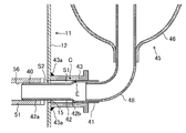
- FIG. 2 is an enlarged vertical sectional view showing the periphery of the suction pipe.
- FIG. 3 is a graph showing the relationship between the rotation speed of the rotary compressor and the sound intensity.
- FIG. 4 is a graph showing the relationship between L2 / L1 and the peak value of the acceleration of the accumulator.
- FIG. 5 is a vertical sectional view showing the configuration of the rotary compressor of the modified example 2.
- the compressor (10) of the present embodiment is a fully sealed rotary compressor.
- the compressor (10) is connected to a refrigerant circuit (not shown) filled with refrigerant.
- a steam compression type refrigeration cycle is performed. Specifically, in the refrigerant circuit, the refrigerant compressed by the compressor (10) is condensed by the condenser, depressurized by the expansion valve, evaporated by the evaporator, and sucked into the compressor (10). ..
- the compressor (10) includes a casing (11), a compression mechanism (50), and a drive mechanism (20).
- the compression mechanism (50) and the drive mechanism (20) are housed inside the casing (11).
- the drive mechanism (20) drives the compression mechanism (50).
- the casing (11) is composed of a vertically long cylindrical closed container.
- the casing (11) has a body portion (12), a lower end plate (13), and an upper end plate (14).
- the body portion (12) is configured in a cylindrical shape extending in the vertical direction (axial direction).
- the body (12) is open at both ends in the vertical direction.
- the lower end plate (13) is fixed to the lower end of the body portion (12).
- the upper end plate (14) is fixed to the upper end of the body (12).
- a suction pipe (40) penetrates and is fixed to the lower part of the body (12).
- a discharge pipe (16) penetrates and is fixed to the upper end plate (14). The detailed configuration around the suction pipe (40) will be described later.
- a storage portion (18) is formed at the bottom of the casing (11). Oil (refrigerator oil) for lubricating the sliding portion of the compression mechanism (50) and the drive shaft (30) described later is stored in the storage portion (18).
- the reservoir (18) is composed of a lower end plate (13) and a lower inner wall of the body (12).
- the drive mechanism (20) has a motor (21) and a drive shaft (30).
- the drive shaft (30) is connected to the motor (21).
- the motor (21) is located above the compression mechanism (50).
- the motor (21) has a stator (22) and a rotor (23).
- the stator (22) is fixed to the inner peripheral surface of the body (12) of the casing (11).
- the rotor (23) penetrates the inside of the stator (22) in the vertical direction.
- a drive shaft (30) is fixed inside the axis of the rotor (23). When the electric motor (21) is energized, the drive shaft (30) is rotationally driven together with the rotor (23).
- the drive shaft (30) is located on the axis of the body portion (12) of the casing (11).
- a refueling pump (30a) is attached to the lower end of the drive shaft (30).
- the refueling pump (30a) conveys the oil stored in the storage unit (18).
- the conveyed oil is supplied to the compression mechanism (50) and the sliding portion of the drive shaft (30) through the oil passage (30b) inside the drive shaft (30).
- the drive shaft (30) has a spindle portion (31) and an eccentric portion (32).
- the eccentric portion (32) is eccentric from the center of rotation of the main shaft portion (31).
- the upper part of the spindle portion (31) is fixed to the rotor (23) of the motor (21).
- the axis of the eccentric portion (32) is eccentric by a predetermined amount from the axis of the spindle portion (31).
- the spindle portion (31) above the eccentric portion (32) in the drive shaft (30) is located inside the front through port (52c) of the front head (52) described later and is rotatably supported.
- the spindle portion (31) below the eccentric portion (32) in the drive shaft (30) is located inside the rear through port (53c) of the rear head (53) and is rotatably supported.
- the compression mechanism (50) is housed in the casing (11) and is located below the motor (21).
- the compression mechanism (50) includes a cylinder (51), a front head (52), a rear head (53), and a piston (60).
- the cylinder (51), front head (52), and rear head (53) are integrated via a fastening member (54).
- the cylinder (51) is a tubular member that covers the outer circumference of the eccentric portion (32).
- the cylinder (51) is fixed to the inner peripheral surface of the lower portion of the body portion (12) of the casing (11).
- the cylinder (51) is formed in a flat, substantially annular shape.
- a circular compression chamber (55) is formed in the center of the cylinder (51).
- the cylinder (51) is formed with a suction port (56) extending in the radial direction.
- the outflow end of the suction port (56) communicates with the compression chamber (55).
- a suction pipe (40) is connected to the inflow end of the suction port (56).
- the front head (52) is laminated on the upper end of the cylinder (51).
- the front head (52) is arranged so as to cover the internal space of the cylinder (51) from above.
- the front head (52) has a front plate portion (52a) and a front protrusion portion (52b).
- the front plate part (52a) is a flat annular part laminated on the cylinder (51).
- the front protruding portion (52b) is a tubular portion that protrudes upward from the central portion of the front plate portion (52a).
- a front through port (52c) is formed in the central portion of the front plate portion (52a) and the front protruding portion (52b) so that the main shaft portion (31) of the drive shaft (30) penetrates.
- the front head (52) is formed with a discharge passage (not shown) that penetrates the front plate portion (52a) in the vertical direction (axial direction).
- the rear head (53) is laminated on the lower end of the cylinder (51).
- the rear head (53) is arranged so as to cover the internal space of the cylinder (51) from below.
- the rear head (53) has a rear plate portion (53a) and a rear protruding portion (53b).
- the rear plate portion (53a) is a flat annular portion laminated on the cylinder (51).
- the rear protruding portion (53b) is a tubular portion that protrudes downward from the central portion of the rear plate portion (53a).
- a rear through port (53c) is formed in the central portion of the rear plate portion (53a) and the rear protruding portion (53b) so that the main shaft portion (31) of the drive shaft (30) penetrates.
- the piston (60) is housed inside the cylinder (51).
- a compression chamber (55) is formed by a cylinder (51) and a piston (60).
- the piston (60) is formed in a perfect circular ring shape.
- a cylindrical eccentric portion (32) is fitted inside the piston (60).
- the inside of the compression chamber (55) is divided into a low pressure chamber and a high pressure chamber by a blade (not shown).
- the compression mechanism (50) of the present embodiment is a so-called swing piston type compression mechanism (50).
- the piston (60) rotates eccentrically, the volume of the high-pressure chamber gradually decreases, and the internal pressure of the high-pressure chamber rises.
- the reed valve (not shown) opens, and the refrigerant in the high-pressure chamber flows out to the outside of the compression mechanism (50) through the discharge passage.
- This high-pressure refrigerant flows upward in the internal space of the casing (11) and passes through the core cut (not shown) of the motor (21).
- the high-pressure refrigerant flowing upward of the motor (21) is sent to the refrigerant circuit from the discharge pipe (16).
- An accumulator (45) is connected to the upstream side of the compressor (10).
- the accumulator (45) temporarily stores the refrigerant before being sucked into the compressor (10), and separates the liquid refrigerant contained in the gas refrigerant into gas and liquid.
- the accumulator (45) has a closed container (46), an inlet pipe (47), and an outlet pipe (48).
- the inlet pipe (47) allows the refrigerant to flow into the closed container (46).
- the outlet pipe (48) allows the refrigerant to flow out of the closed container (46).
- the closed container (46) is composed of a vertically long cylindrical member.
- An inlet pipe (47) is connected to the upper part of the closed container (46). The lower end of the inlet pipe (47) opens at a position closer to the upper part in the internal space of the closed container (46).
- An outlet pipe (48) is connected to the bottom of the closed container (46).
- the outlet pipe (48) is made of an iron-based material (for example, SPCC, SPCD, etc.).
- the outlet pipe (48) extends upward in the closed container (46).
- the upper end of the outlet pipe (48) opens at a position closer to the upper part in the internal space of the closed container (46).
- the outlet pipe (48) extends downward from the lower end of the closed container (46) and then bends toward the suction pipe (40) of the compressor (10).
- the lower end of the outlet pipe (48) is connected to the inflow end of the suction pipe (40).
- the suction pipe (40) communicates with the suction port (56) of the cylinder (51) and is arranged inside the joint pipe (43).
- the joint pipe (43) is fixed to the through hole (15) of the casing (11).
- the inner peripheral surface of the joint pipe (43) and the inner peripheral surface of the through hole (15) of the casing (11) are almost the same.
- the inner peripheral surface of the joint pipe (43) and the inner peripheral surface of the through hole (15) of the casing (11) are continuous.
- the through hole (15) of the casing (11) is formed downward in the body portion (12) of the casing (11).
- the through hole (15) of the casing (11) is formed at a position facing the suction port (56).
- the fitting pipe (43) is arranged so as to face the suction port (56) of the cylinder (51).
- the joint pipe (43) is made of an iron-based material (for example, SPCC, SPCD, etc.).
- the joint pipe (43) is a cylindrical member.
- the joint pipe (43) extends from the body portion (12) of the casing (11) toward the outside of the casing (11).
- the thickness of the joint pipe (43) is larger than the thickness of the casing (11).
- the inner diameter of the joint pipe (43) is formed to be constant over the total length in the axial direction.
- the joint pipe (43) is fixed with its tip in contact with the body (12) of the casing (11). Specifically, the joint pipe (43) is fixed by being welded to the body portion (12) of the casing (11).
- the joint pipe (43) has a welded portion (43a).
- the welded portion (43a) is formed on the outer edge of the joint pipe (43) on the casing (11) side over the entire circumference of the outer edge.
- the suction pipe (40) extends through the inside of the fitting pipe (43) to the outside of the casing (11).
- the suction tube (40) is made of an iron-based material (for example, SPCC, SPCD, etc.).
- the suction tube (40) is a cylindrical member.
- the suction tube (40) has a large diameter portion (41) and a small diameter portion (42).
- the large diameter portion (41) is formed on the inflow side of the suction pipe (40).
- the large diameter portion (41) is fixed to the inner peripheral surface of the joint pipe (43).
- the outflow end of the outlet pipe (48) is fixed to the inner peripheral surface of the large diameter portion (41).
- the small diameter portion (42) is formed on the outflow side of the suction pipe (40).
- the outer diameter of the small diameter portion (42) is smaller than the outer diameter of the large diameter portion (41).
- the small diameter portion (42) includes a main body portion (42a) and a step portion (42b).
- the main body portion (42a) is provided on the outflow side of the small diameter portion (42).
- the outflow end of the main body (42a) is connected to the suction port (56) of the cylinder (51).
- the outer diameter of the main body (42a) is smaller than the inner diameter of the through hole (15) of the casing (11).
- the main body portion (42a) passes through the through hole (15) of the casing (11).
- the step portion (42b) is provided in the middle of the suction pipe (40) and is continuous with the inflow end in the main body portion (42a).
- the step portion (42b) is a portion connecting the main body portion (42a) and the large diameter portion (41).
- the outer diameter and inner diameter of the step portion (42b) gradually increase from the main body portion (42a) toward the large diameter portion (41).
- the end (E) on the inflow side of the stepped portion (42b) of the small diameter portion (42) is located on the accumulator (45) side of the central portion (C) in the axial direction of the joint pipe (43).
- a first gap (S1) is formed between the outer peripheral surface of the small diameter portion (42) and the inner peripheral surface of the joint pipe (43).
- the first gap (S1) is continuously formed from the end portion of the joint pipe (43) on the casing (11) side to the connection portion of the suction pipe (40) with the large diameter portion (41). ..
- the suction pipe (40) is not in contact with the joint pipe (43) between the end portion of the joint pipe (43) on the casing (11) side and the connection portion with the suction pipe (40).
- the first gap (S1) corresponds to the gap of the present disclosure.
- the first gap (S1) is continuously formed between the outer peripheral surface of the small diameter portion (42) of the suction pipe (40) and the inner peripheral surface of the joint pipe (43), thereby compressing. Even if the vibration generated by the mechanism (50) propagates to the suction pipe (40), the small diameter portion (42) vibrates without contacting the joint pipe (43). As a result, the vibration is damped in the small diameter portion (42).
- annular second gap (S2) is formed between the main body portion (42a) of the small diameter portion (42) and the through hole (15) of the casing (11).
- a space including the first gap (S1) and the second gap (S2) is formed between the connection portion of the compression mechanism (50) and the large diameter portion (41). This space allows vibration of the small diameter portion (42). As a result, the vibration can be further damped in the small diameter portion (42).
- the inflow side end portion (E) of the small diameter portion (42) is located closer to the accumulator (45) side than the axial central portion (C) of the joint pipe (43), whereby the suction pipe (40).
- the small diameter part (42) can be lengthened. As a result, the vibration is further damped in the small diameter portion (42).
- the total length in the axial direction of the suction pipe (40) is L1
- the axial length of the small diameter portion (42) of the suction pipe (40) is L2.
- L2 is 58% or more of L1 (L2 ⁇ L1 ⁇ 0.58).
- the joint pipe (43) is made of an iron-based material, the rigidity of the joint pipe (43) is high. As a result, the vibration transmitted from the compression mechanism (50) is insulated at the connection portion between the large diameter portion (41) of the suction pipe (40) and the joint pipe (43), and it becomes difficult for the vibration to be transmitted to the accumulator (45). ..
- the joint pipe (43) is connected to the casing by the welded portion (43a), the rigidity of the welded portion (43a) is high. As a result, the vibration transmitted from the compression mechanism (50) to the suction pipe (40) can be further insulated by the joint pipe (43).
- the compressor (10) of the present embodiment is manufactured by connecting the accumulator (45) to the compression mechanism (50).
- a welding process, a press-fitting process, a fitting process, and a brazing process are performed in order.
- the welding process is a process of fixing the joint pipe (43) to the casing (11).
- the joint pipe (43) is casing (11) so that the inner peripheral surface of the through hole (15) formed in the casing (11) and the inner peripheral surface of the joint pipe (43) coincide with each other.
- the joint pipe (43) brought into contact with the body portion (12) is welded to the casing (11).
- the welded portion (43a) is formed.
- the press-fitting process is a step of press-fitting the suction pipe (40) into the compression mechanism (50).
- the compression mechanism (50) is arranged so that the suction port (56) of the cylinder (51) in the compression mechanism (50) faces the joint pipe (43).
- the suction pipe (40) is press-fitted into the suction port (56) of the cylinder (51) from the open side of the joint pipe (43).
- the suction pipe (40) is provided so that the first gap (S1) is formed between the outer peripheral surface of the small diameter portion (42) of the suction pipe (40) and the inner peripheral surface of the joint pipe (43). Press-fit in the axial direction. Specifically, the suction pipe (40) is press-fitted so that the axial length of the suction pipe (40) in the first gap (S1) becomes a predetermined length.
- the outlet pipe (48) of the accumulator (45) is fitted to the open end of the suction pipe (40).
- FIG. 3 is a graph showing the relationship between the rotation speed obtained by measuring the compressor (10) and the sound intensity.
- the first gap (S1) is not formed between the outer peripheral surface of the small diameter portion (42) of the suction pipe (40) and the inner peripheral surface of the joint pipe (43). This is the result when the compressor is measured.
- the solid line connecting the cross marks in the figure is the result when the compressor (10) of this embodiment is measured. Specifically, it is the result of measuring the compressor (10) in which the first gap (S1) is formed between the outer peripheral surface of the small diameter portion (42) and the inner peripheral surface of the joint pipe (43). be.
- the joint pipe (43) in this experiment is made of an iron-based material.
- the compressor (10) of the present embodiment is compared with the compressor having no first gap (S1) between the small diameter portion (42) and the joint pipe (43). It was confirmed that the sound was getting quieter. As a result, the first gap (S1) is formed between the outer peripheral surface of the small diameter portion (42) and the inner peripheral surface of the joint pipe (43), so that the compression mechanism (50) can be changed to the accumulator (45). It was confirmed that the transmitted vibration can be suppressed.
- FIG. 4 is a graph showing the relationship between L2 / L1 obtained from the simulation and the peak value of the acceleration of the accumulator. Specifically, FIG. 4 is a graph plotting the peak value when the vibration of the accumulator (45) when a force having a magnitude of 1N is applied to the suction pipe (40) is shown by acceleration. FIG. 4 plots the peak value of the acceleration of the accumulator (45) in the compressor (10) when the ratio of L2 / L1 is 57%, 64%, and 76%.
- the feature (1) of the present embodiment is that a first gap (S1) is formed between the outer peripheral surface of the small diameter portion (42) of the suction pipe (40) and the inner peripheral surface of the joint pipe (43). That is.
- the joint pipe (43) is made of a copper-based material. Since the conventional joint pipe (43) has low rigidity, vibration from the compression mechanism (50) is easily transmitted to the joint pipe (43) via the suction pipe (40).
- the joint pipe (43) of the present embodiment is made of an iron-based material, the rigidity of the joint pipe (43) is higher than that of the copper-based material. This makes it possible to insulate the vibration from the compression mechanism (50) at the connection portion between the large diameter portion (41) of the suction pipe (40) and the joint pipe (43). As a result, the vibration transmitted from the compression mechanism (50) to the accumulator (45) can be suppressed.
- the joint pipe (43) is made of iron-based material, the cost can be reduced as compared with that of copper-based material.
- the feature (2) of the present embodiment is that the first gap (S1) is continuously formed from the end portion of the joint pipe (43) on the casing (11) side to the connection portion with the suction pipe (40). That is.
- the small diameter portion (42) of the suction pipe (40) can vibrate without being hindered by the joint pipe (43), so that the vibration can be further damped.
- the feature (3) of the present embodiment is that the end portion (E) on the inflow side of the small diameter portion (42) is located on the accumulator (45) side of the central portion (C) in the axial direction of the joint pipe (43). That is. As a result, the small diameter portion (42) of the suction pipe (40) can be lengthened, so that vibration can be further damped.
- the feature (4) of the present embodiment is that the joint pipe (43) has a welded portion (43a) to be welded to the casing (11). As a result, the rigidity of the joint portion between the joint pipe (43) and the casing (11) can be increased, so that the vibration from the compression mechanism (50) can be further insulated by the joint pipe (43).
- the joint pipe (43) and the casing (11) are joined by silver brazing. Since the compressor (10) of the present embodiment is joined by welding, the cost can be reduced as compared with silver brazing.
- the feature (5) of this embodiment is that the thickness of the joint pipe (43) is larger than the thickness of the casing (11). As a result, when the joint pipe (43) and the casing (11) are welded, deformation of the joint pipe (43) due to heat can be suppressed.
- the feature (6) of this embodiment is that the outlet pipe (48) is made of an iron-based material.
- the outlet pipe is configured by connecting a copper pipe and an iron pipe. Since the outlet pipe (48) of the present embodiment is composed of only an iron-based material, the rigidity of the outlet pipe (48) can be increased. Thereby, the vibration from the compression mechanism (50) can be further insulated by the outlet pipe (48). Further, in the outlet pipe (48) of the present embodiment, the number of parts of the outlet pipe (48) can be reduced and the material cost can be reduced, so that the cost can be reduced.
- the feature (7) of the present embodiment is that the axial length L2 in the small diameter portion (42) of the suction pipe (40) is 58% or more of the axial total length L1 in the suction pipe (40). .. Since the length of the small diameter portion (42) is long to some extent, the vibration from the compression mechanism (50) is easily attenuated by the small diameter portion (42) of the suction pipe (40).
- the feature (8) of the present embodiment is a casing (11), a compression mechanism (50) housed in the casing (11) and having a suction port (56), and a joint pipe fixed to the casing (11). (43), a suction pipe (40) arranged inside the joint pipe (43) and communicating with the suction port (56) of the compression mechanism (50), and connected to the inflow end of the suction pipe (40). It is provided with an accumulator (45) having an outlet pipe (48) to be formed, and the suction pipe (40) is formed on the inflow side of the suction pipe (40) and fixed to the inner peripheral surface of the joint pipe (43).
- the casing (11) has a large-diameter portion (41) and a small-diameter portion (42) formed on the outflow side of the suction pipe (40) and having an outer diameter smaller than that of the large-diameter portion (41).
- a welding step of welding the suction pipe (11) to the casing (11) and a press-fitting step of press-fitting the suction pipe (40) into the suction port (56) of the compression mechanism (50) are included.
- a first gap (S1) is formed between the outer peripheral surface of (42) and the inner peripheral surface of the joint pipe (43), and a second gap (S1) is formed between the small diameter portion (42) and the through hole (15). It is press-fitting so that S2) is formed.
- the small diameter portion (42) comes into contact with the joint pipe (43) by the first gap (S1) and the second gap (S2). Since it can vibrate without any vibration, the vibration of the compression mechanism (50) can be damped by the small diameter portion (42).
- the second gap (S2) is formed. And the suction port (56) of the compression mechanism (50) can be easily aligned.
- the tip of the joint pipe (43) may be fitted into the through hole (15) of the casing (11) of the joint pipe (43). Also in this modification, the first gap (S1) is formed between the outer peripheral surface of the small diameter portion (42) of the suction pipe (40) and the inner peripheral surface of the joint pipe (43). Thereby, the same effect as that of the embodiment can be obtained.
- the cylinder (51) and the piston (60) are provided at intervals in the vertical direction (axial direction).
- the compression mechanism (50) includes a front head (52), a front cylinder (51), a middle plate (58), a rear cylinder (51), and a rear head (53). It is laminated.
- Pistons (60,60) are housed in the front and rear cylinders (51,51), respectively.
- the front and rear cylinders (51,51) are formed with suction ports (56,56) extending in the radial direction, respectively.
- the drive shaft (30) is provided with two eccentric parts (32,32) corresponding to the pistons (60,60) on the front side and the rear side.
- An eccentric portion (32) is fitted in the piston (60).
- Through holes (15,15) are formed in the body portion (12) of the casing (11) at positions facing the suction ports (56,56) on the front side and the rear side, respectively.
- Joint pipes (43,43) are connected to the through holes (15) of the casing (11), respectively.
- the suction pipes (40,40) are connected to the suction ports (56,56) of the cylinders (51,51) on the front side and the rear side, respectively, and the casing (43,43) passes through the inside of the joint pipe (43,43). It extends to the outside of 11).
- the outlet pipes (48,48) of the accumulator (45) are connected to the suction pipes (40,40) on the front side and the rear side, respectively.
- this modification targets a two-cylinder compressor (10) provided with two cylinders (51,51) and two pistons (60,60). Even in the two-cylinder compressor (10), there is a first gap (S1) between the outer peripheral surface of the small diameter portion (42) of one suction pipe (40) and the inner peripheral surface of one joint pipe (43). ) Is formed. Further, in the small diameter portion (42), a space including the first gap (S1) and the second gap (S2) is formed between the connection portion of the compression mechanism (50) and the large diameter portion (41). ..
- the vibration transmitted from the compression mechanism (50) to the accumulator (45) can be suppressed as in the embodiment.
- the outlet pipe (48) is made of only iron-based material, the number of parts can be further reduced and the cost can be further reduced.
- the above embodiment may have the following configuration.
- the compression mechanism (50) of the compressor (10) of the above embodiment is a swing piston type.
- the compression mechanism (50) may be of a rolling piston type.
- the compression chamber (55) is partitioned by a vane separated from the piston (60) instead of the blade of the embodiment.
- the present disclosure is useful for rotary compressors.
Landscapes
- Engineering & Computer Science (AREA)
- Mechanical Engineering (AREA)
- General Engineering & Computer Science (AREA)
- Physics & Mathematics (AREA)
- Thermal Sciences (AREA)
- Applications Or Details Of Rotary Compressors (AREA)
- Compressor (AREA)
Abstract
継手管(43)は、ケーシング(11)に固定される。吸入管(40)は、継手管(43)の内部に配置されるとともに圧縮機構(50)の吸入口(56)に連通する。吸入管(40)は、吸入管(40)の流入側に形成され、継手管(43)の内周面に固定される大径部(41)と、吸入管(40)の流出側に形成され、大径部(41)よりも外径が小さい小径部(42)とを有する。継手管(43)は、鉄系材料で構成される。吸入管(40)の小径部(42)の外周面と前記継手管(43)の内周面との間には、隙間(S1)が形成される。
Description
本開示は、回転式圧縮機に関する。
従来、空気調和装置等に使用される圧縮機が知られている。特許文献1には、全密閉型で縦型の圧縮機が開示されている。この圧縮機では、ケーシングに圧縮機構が収容されるとともに、ケーシングに継手管が接続されている。
圧縮機の上流側には、アキュームレータが接続されている。アキュームレータは、密閉容器と、密閉容器から冷媒を流出させる出口管とを有する。出口管は、吸入管を介して圧縮機構と接続される。吸入管は、継手管の内部に配置され、アキュームレータの密閉容器と圧縮機構とを繋いでいる。
上記特許文献1の圧縮機では、圧縮機構の振動が吸入管から継手管及び出口管の順に伝搬する。圧縮機構の振動が伝搬すると、アキュームレータの密閉容器が振動して、騒音が発生することがあった。
本開示の目的は、圧縮機構からアキュームレータに伝わる振動を抑制することである。
本開示の第1の態様は、
ケーシング(11)と、
前記ケーシング(11)に収容されるとともに吸入口(56)を有する圧縮機構(50)と、
前記ケーシング(11)に固定される継手管(43)と、
前記継手管(43)の内部に配置されるとともに前記圧縮機構(50)の前記吸入口(56)に連通する吸入管(40)と、
前記吸入管(40)の流入端に接続される出口管(48)を有するアキュームレータ(45)とを備え、
前記吸入管(40)は、
前記吸入管(40)の流入側に形成され、前記継手管(43)の内周面に固定される大径部(41)と、
前記吸入管(40)の流出側に形成され、前記大径部(41)よりも外径が小さい小径部(42)とを有し、
前記継手管(43)は、鉄系材料で構成され、
前記吸入管(40)の小径部(42)の外周面と前記継手管(43)の内周面との間には、隙間(S1)が形成される
回転式圧縮機である。
ケーシング(11)と、
前記ケーシング(11)に収容されるとともに吸入口(56)を有する圧縮機構(50)と、
前記ケーシング(11)に固定される継手管(43)と、
前記継手管(43)の内部に配置されるとともに前記圧縮機構(50)の前記吸入口(56)に連通する吸入管(40)と、
前記吸入管(40)の流入端に接続される出口管(48)を有するアキュームレータ(45)とを備え、
前記吸入管(40)は、
前記吸入管(40)の流入側に形成され、前記継手管(43)の内周面に固定される大径部(41)と、
前記吸入管(40)の流出側に形成され、前記大径部(41)よりも外径が小さい小径部(42)とを有し、
前記継手管(43)は、鉄系材料で構成され、
前記吸入管(40)の小径部(42)の外周面と前記継手管(43)の内周面との間には、隙間(S1)が形成される
回転式圧縮機である。
第1の態様では、圧縮機構(50)で生じた振動は、吸入管(40)、継手管(43)、及び出口管(48)の順に伝わる。吸入管(40)の小径部(42)の外周面と継手管(43)の内周面との間に隙間(S1)が形成されているので、圧縮機構(50)の振動が吸入管(40)に伝わっても、小径部(42)は継手管(43)の内周面に接触することなく振動する。このため、圧縮機構(50)から伝搬した振動が小径部(42)で減衰される。加えて、継手管(43)が鉄系材料で構成されているので、継手管(43)の剛性が高い。このため、吸入管(40)の大径部(41)と継手管(43)との接続部分で振動を絶縁できる。これにより、圧縮機構(50)からアキュームレータ(45)に伝わる振動を抑制できる。
本開示の第2の態様は、第1の態様の回転式圧縮機において、
前記小径部(42)における流入側の端部(E)は、前記継手管(43)における軸方向の中央部(C)よりも前記アキュームレータ(45)側に位置する。
前記小径部(42)における流入側の端部(E)は、前記継手管(43)における軸方向の中央部(C)よりも前記アキュームレータ(45)側に位置する。
第2の態様では、吸入管(40)における小径部(42)の流入側の端部(E)が、継手管(43)における軸方向の中央部(C)よりもアキュームレータ(45)側に位置することにより、小径部(42)を長くできる。これにより、圧縮機構(50)から吸入管(40)に伝わった振動をより減衰できる。
本開示の第3の態様は、第1又は第2の態様の回転式圧縮機において、
前記継手管(43)は、前記ケーシング(11)に溶接される溶接部(43a)を有する。
前記継手管(43)は、前記ケーシング(11)に溶接される溶接部(43a)を有する。
第3の態様では、継手管(43)とケーシング(11)とを溶接することにより、溶接部(43a)の剛性を高くできる。これにより、圧縮機構(50)から吸入管(40)に伝わった振動を継手管(43)でさらに絶縁できる。
本開示の第4の態様は、第3の態様の回転式圧縮機において、
前記継手管(43)の厚みは、前記ケーシング(11)の厚みよりも大きい。
前記継手管(43)の厚みは、前記ケーシング(11)の厚みよりも大きい。
第4の態様では、継手管(43)の厚みがケーシング(11)の厚みよりも大きいので、継手管(43)とケーシング(11)とを溶接した際に、熱による継手管(43)の変形を抑制できる。
本開示の第5の態様は、第1~第4の態様のいずれか1つの回転式圧縮機において、
前記出口管(48)は、鉄系材料で構成される。
前記出口管(48)は、鉄系材料で構成される。
第5の態様では、出口管(48)を鉄系材料にすることで、出口管(48)の剛性を高くできる。これにより、圧縮機構(50)から吸入管(40)に伝わった振動を出口管(48)でさらに絶縁できる。
本開示の第6の態様は、第1~第5の態様のいずれか1つの回転式圧縮機(10)において、
前記吸入管(40)の小径部(42)における軸方向の長さL2は、前記吸入管(40)における軸方向の全長L1の58%以上である。
前記吸入管(40)の小径部(42)における軸方向の長さL2は、前記吸入管(40)における軸方向の全長L1の58%以上である。
第6の態様では、小径部(42)における軸方向の長さがある程度長いことにより、圧縮機構(50)からの振動が吸入管(40)の小径部(42)によって減衰されやすくなる。
以下、本開示の実施形態について図面を参照しながら説明する。なお、以下の実施形態は、本質的に好ましい例示であって、本発明、その適用物、あるいはその用途の範囲を制限することを意図するものではない。
《実施形態》
実施形態について説明する。
実施形態について説明する。
図1に示すように、本実施形態の圧縮機(10)は、全密閉型の回転式圧縮機である。圧縮機(10)は、冷媒が充填された冷媒回路(図示省略)に接続されている。冷媒回路では、蒸気圧縮式の冷凍サイクルが行われる。具体的には、冷媒回路では、圧縮機(10)で圧縮された冷媒が、凝縮器で凝縮し、膨張弁で減圧された後、蒸発器で蒸発し、圧縮機(10)に吸入される。
-圧縮機の構成-
圧縮機(10)は、ケーシング(11)と、圧縮機構(50)と、駆動機構(20)とを備えている。圧縮機構(50)及び駆動機構(20)は、ケーシング(11)の内部に収容されている。駆動機構(20)は、圧縮機構(50)を駆動させる。
圧縮機(10)は、ケーシング(11)と、圧縮機構(50)と、駆動機構(20)とを備えている。圧縮機構(50)及び駆動機構(20)は、ケーシング(11)の内部に収容されている。駆動機構(20)は、圧縮機構(50)を駆動させる。
〈ケーシング〉
ケーシング(11)は、縦長の円筒状の密閉容器で構成される。ケーシング(11)は、胴部(12)と、下部鏡板(13)と、上部鏡板(14)とを有している。胴部(12)は、上下方向(軸方向)に延びる円筒状に構成されている。胴部(12)は、上下方向の両端が開口している。下部鏡板(13)は、胴部(12)の下端に固定されている。上部鏡板(14)は、胴部(12)の上端に固定されている。
ケーシング(11)は、縦長の円筒状の密閉容器で構成される。ケーシング(11)は、胴部(12)と、下部鏡板(13)と、上部鏡板(14)とを有している。胴部(12)は、上下方向(軸方向)に延びる円筒状に構成されている。胴部(12)は、上下方向の両端が開口している。下部鏡板(13)は、胴部(12)の下端に固定されている。上部鏡板(14)は、胴部(12)の上端に固定されている。
胴部(12)の下部には、吸入管(40)が貫通して固定されている。上部鏡板(14)には、吐出管(16)が貫通して固定されている。なお、吸入管(40)周辺の詳細な構成については後述する。
ケーシング(11)の底部には、貯留部(18)が形成されている。貯留部(18)には、圧縮機構(50)及び後述する駆動軸(30)の摺動部を潤滑するための油(冷凍機油)が貯留される。貯留部(18)は、下部鏡板(13)及び胴部(12)の下部の内壁によって構成される。
〈駆動機構〉
駆動機構(20)は、電動機(21)と、駆動軸(30)とを有する。駆動軸(30)は、電動機(21)と連結している。
駆動機構(20)は、電動機(21)と、駆動軸(30)とを有する。駆動軸(30)は、電動機(21)と連結している。
(電動機)
電動機(21)は、圧縮機構(50)の上方に配置されてる。電動機(21)は、固定子(22)と、回転子(23)とを有している。
電動機(21)は、圧縮機構(50)の上方に配置されてる。電動機(21)は、固定子(22)と、回転子(23)とを有している。
固定子(22)は、ケーシング(11)の胴部(12)の内周面に固定されている。回転子(23)は、固定子(22)の内部を上下方向に貫通している。回転子(23)の軸心内部には、駆動軸(30)が固定される。電動機(21)が通電されると、回転子(23)とともに駆動軸(30)が回転駆動される。
(駆動軸)
駆動軸(30)は、ケーシング(11)の胴部(12)の軸心上に位置している。駆動軸(30)の下端には、給油ポンプ(30a)が取り付けられている。給油ポンプ(30a)は、貯留部(18)に貯留された油を搬送する。搬送された油は、駆動軸(30)の内部の油通路(30b)を通じて、圧縮機構(50)及び駆動軸(30)の摺動部へ供給される。
駆動軸(30)は、ケーシング(11)の胴部(12)の軸心上に位置している。駆動軸(30)の下端には、給油ポンプ(30a)が取り付けられている。給油ポンプ(30a)は、貯留部(18)に貯留された油を搬送する。搬送された油は、駆動軸(30)の内部の油通路(30b)を通じて、圧縮機構(50)及び駆動軸(30)の摺動部へ供給される。
駆動軸(30)は、主軸部(31)と、偏心部(32)とを有している。偏心部(32)は、主軸部(31)の回転中心から偏心している。主軸部(31)の上部は、電動機(21)の回転子(23)に固定される。偏心部(32)の軸心は、主軸部(31)の軸心から所定量だけ偏心している。
駆動軸(30)における偏心部(32)よりも上部の主軸部(31)は、後述するフロントヘッド(52)のフロント貫通口(52c)の内部に位置して回転可能に支持されている。駆動軸(30)における偏心部(32)よりも下部の主軸部(31)は、リアヘッド(53)のリア貫通口(53c)の内部に位置して回転可能に支持されている。
〈圧縮機構〉
圧縮機構(50)は、ケーシング(11)に収容されるとともに、電動機(21)の下方に配置されている。圧縮機構(50)は、シリンダ(51)と、フロントヘッド(52)と、リアヘッド(53)と、ピストン(60)とを備えている。シリンダ(51)、フロントヘッド(52)、及びリアヘッド(53)は、締結部材(54)を介して一体化されている。
圧縮機構(50)は、ケーシング(11)に収容されるとともに、電動機(21)の下方に配置されている。圧縮機構(50)は、シリンダ(51)と、フロントヘッド(52)と、リアヘッド(53)と、ピストン(60)とを備えている。シリンダ(51)、フロントヘッド(52)、及びリアヘッド(53)は、締結部材(54)を介して一体化されている。
シリンダ(51)は、偏心部(32)の外周を覆う筒状の部材である。シリンダ(51)は、ケーシング(11)の胴部(12)における下部の内周面に固定されている。シリンダ(51)は、扁平な略環状に形成されている。
シリンダ(51)の中央部には、円形状の圧縮室(55)が形成されている。シリンダ(51)には、径方向に延びる吸入口(56)が形成されている。吸入口(56)の流出端は、圧縮室(55)と連通している。吸入口(56)の流入端には、吸入管(40)が接続されている。
フロントヘッド(52)は、シリンダ(51)の上端部に積層されている。フロントヘッド(52)は、シリンダ(51)の内部空間を上方から覆うように配置されている。フロントヘッド(52)は、フロントプレート部(52a)と、フロント突出部(52b)とを有している。
フロントプレート部(52a)は、シリンダ(51)に積層する扁平な環状の部分である。フロント突出部(52b)は、フロントプレート部(52a)の中央部から上方に突出する筒状の部分である。フロントプレート部(52a)及びフロント突出部(52b)の中央部には、駆動軸(30)の主軸部(31)が貫通するようにフロント貫通口(52c)が形成されている。フロントヘッド(52)には、フロントプレート部(52a)を上下方向(軸方向)に貫通する吐出通路(図示省略)が形成されている。
リアヘッド(53)は、シリンダ(51)の下端部に積層されている。リアヘッド(53)は、シリンダ(51)の内部空間を下方から覆うように配置されている。リアヘッド(53)は、リアプレート部(53a)と、リア突出部(53b)とを有している。
リアプレート部(53a)は、シリンダ(51)に積層する扁平な環状の部分である。リア突出部(53b)は、リアプレート部(53a)の中央部から下方に突出する筒状の部分である。リアプレート部(53a)及びリア突出部(53b)の中央部には、駆動軸(30)の主軸部(31)が貫通するようにリア貫通口(53c)が形成されている。
ピストン(60)は、シリンダ(51)の内部に収容されている。シリンダ(51)とピストン(60)とによって、圧縮室(55)が形成されている。ピストン(60)は、真円形の環状に形成されている。ピストン(60)の内部には、円柱状の偏心部(32)が嵌め込まれている。圧縮室(55)の内部は、ブレード(図示省略)によって、低圧室と高圧室とに区画されている。本実施形態の圧縮機構(50)は、いわゆる揺動ピストン式の圧縮機構(50)である。
-圧縮機の運転動作-
ピストン(60)は、駆動軸(30)の回転駆動に伴って、圧縮室(55)内で偏心回転する。ピストン(60)の偏心回転に伴い低圧室の容積が徐々に大きくなると、吸入管(40)を流れる冷媒が吸入口(56)から低圧室へ吸入されていく。そして、低圧室が吸入口(56)から遮断されると、遮断された空間が高圧室を構成する。
ピストン(60)は、駆動軸(30)の回転駆動に伴って、圧縮室(55)内で偏心回転する。ピストン(60)の偏心回転に伴い低圧室の容積が徐々に大きくなると、吸入管(40)を流れる冷媒が吸入口(56)から低圧室へ吸入されていく。そして、低圧室が吸入口(56)から遮断されると、遮断された空間が高圧室を構成する。
さらにピストン(60)が偏心回転すると、高圧室の容積が徐々に小さくなり、高圧室の内圧が上昇する。高圧室の内圧が所定の圧力を超えるとリード弁(図示省略)が開き、高圧室の冷媒が吐出通路を通じて、圧縮機構(50)の外部へ流出する。
この高圧冷媒は、ケーシング(11)の内部空間を上方へ流れ、電動機(21)のコアカット(図示省略)等を通過する。電動機(21)の上方へ流出した高圧冷媒は、吐出管(16)より冷媒回路へ送られる。
-アキュームレータの構成-
圧縮機(10)の上流側には、アキュームレータ(45)が接続されている。アキュームレータ(45)は、圧縮機(10)に吸入される前の冷媒を一時的に貯留するとともに、ガス冷媒に含まれる液冷媒を気液分離するものである。
圧縮機(10)の上流側には、アキュームレータ(45)が接続されている。アキュームレータ(45)は、圧縮機(10)に吸入される前の冷媒を一時的に貯留するとともに、ガス冷媒に含まれる液冷媒を気液分離するものである。
アキュームレータ(45)は、密閉容器(46)と、入口管(47)と、出口管(48)とを有する。入口管(47)は、密閉容器(46)に冷媒を流入させる。出口管(48)は、密閉容器(46)から冷媒を流出させる。
密閉容器(46)は、縦長の円筒状の部材で構成されている。密閉容器(46)の上部には、入口管(47)が接続されている。入口管(47)の下端部は、密閉容器(46)の内部空間における上部寄りの位置に開口している。
密閉容器(46)の下部には、出口管(48)が接続されている。出口管(48)は、鉄系材料(例えば、SPCC、SPCD等)で構成されている。出口管(48)は、密閉容器(46)内を上方向に延びている。出口管(48)の上端部は、密閉容器(46)の内部空間における上部寄りの位置に開口している。出口管(48)は、密閉容器(46)の下端から下方に延びた後に、圧縮機(10)の吸入管(40)に向かって屈曲している。出口管(48)の下端部は、吸入管(40)の流入端に接続されている。
-吸入管周辺の詳細な構成-
図2に示すように、吸入管(40)は、シリンダ(51)の吸入口(56)に連通するとともに、継手管(43)の内部に配置される。
図2に示すように、吸入管(40)は、シリンダ(51)の吸入口(56)に連通するとともに、継手管(43)の内部に配置される。
(継手管)
継手管(43)は、ケーシング(11)の貫通孔(15)に固定されている。継手管(43)の内周面とケーシング(11)の貫通孔(15)の内周面とは、概ね一致している。言い換えると、継手管(43)の内周面とケーシング(11)の貫通孔(15)の内周面とは、連続している。ケーシング(11)の貫通孔(15)は、ケーシング(11)の胴部(12)における下方に形成されている。ケーシング(11)の貫通孔(15)は、吸入口(56)に対向する位置に形成されている。言い換えると、継手管(43)は、シリンダ(51)の吸入口(56)と対向するように配置されている。
継手管(43)は、ケーシング(11)の貫通孔(15)に固定されている。継手管(43)の内周面とケーシング(11)の貫通孔(15)の内周面とは、概ね一致している。言い換えると、継手管(43)の内周面とケーシング(11)の貫通孔(15)の内周面とは、連続している。ケーシング(11)の貫通孔(15)は、ケーシング(11)の胴部(12)における下方に形成されている。ケーシング(11)の貫通孔(15)は、吸入口(56)に対向する位置に形成されている。言い換えると、継手管(43)は、シリンダ(51)の吸入口(56)と対向するように配置されている。
継手管(43)は、鉄系材料(例えば、SPCC、SPCD等)で構成されている。継手管(43)は、円筒状の部材である。継手管(43)は、ケーシング(11)の胴部(12)からケーシング(11)の外部に向かって延びている。継手管(43)の厚みは、ケーシング(11)の厚みよりも大きい。継手管(43)の内径は、軸方向の全長において一定に形成されている。
継手管(43)は、その先端がケーシング(11)の胴部(12)と接触した状態で固定されている。具体的には、継手管(43)は、ケーシング(11)の胴部(12)に溶接されることで固定されている。継手管(43)は、溶接部(43a)を有する。溶接部(43a)は、継手管(43)におけるケーシング(11)側の外縁に、該外縁の全周に亘って形成されている。
(吸入管)
吸入管(40)は、継手管(43)の内部を通ってケーシング(11)の外部に延びている。吸入管(40)は、鉄系材料(例えば、SPCC、SPCD等)で構成されている。吸入管(40)は円筒状の部材である。吸入管(40)は、大径部(41)と、小径部(42)とを有する。
吸入管(40)は、継手管(43)の内部を通ってケーシング(11)の外部に延びている。吸入管(40)は、鉄系材料(例えば、SPCC、SPCD等)で構成されている。吸入管(40)は円筒状の部材である。吸入管(40)は、大径部(41)と、小径部(42)とを有する。
大径部(41)は、吸入管(40)の流入側に形成されている。大径部(41)は、継手管(43)の内周面に固定される。大径部(41)の内周面には、出口管(48)の流出端が固定される。
小径部(42)は、吸入管(40)の流出側に形成されている。小径部(42)の外径は、大径部(41)の外径よりも小さい。小径部(42)は、本体部(42a)と段差部(42b)とを含む。本体部(42a)は、小径部(42)の流出側に設けられている。本体部(42a)の流出端は、シリンダ(51)の吸入口(56)に接続されている。本体部(42a)の外径は、ケーシング(11)の貫通孔(15)の内径よりも小さい。本体部(42a)は、ケーシング(11)の貫通孔(15)を通っている。
段差部(42b)は、吸入管(40)の途中に設けられ、本体部(42a)における流入端と連続する。段差部(42b)は、本体部(42a)と大径部(41)とを繋ぐ部分である。段差部(42b)の外径及び内径は、本体部(42a)から大径部(41)に向かって次第に拡大している。
小径部(42)の段差部(42b)における流入側の端部(E)は、継手管(43)における軸方向の中央部(C)よりもアキュームレータ(45)側に位置する。小径部(42)の外周面と継手管(43)の内周面との間には、第1隙間(S1)が形成されている。第1隙間(S1)は、継手管(43)におけるケーシング(11)側の端部から吸入管(40)の大径部(41)との接続部分までの間において連続して形成されている。言い換えると、継手管(43)におけるケーシング(11)側の端部から吸入管(40)との接続部分までの間において、吸入管(40)は、継手管(43)に接触していない。なお、第1隙間(S1)は、本開示の隙間に対応する。
このように、吸入管(40)の小径部(42)の外周面と継手管(43)の内周面との間に第1隙間(S1)が連続して形成されていることにより、圧縮機構(50)で生じた振動が吸入管(40)に伝搬しても、小径部(42)は継手管(43)に接触することなく振動する。これにより、小径部(42)において振動が減衰される。
また、小径部(42)の本体部(42a)とケーシング(11)の貫通孔(15)との間に、環状の第2隙間(S2)が形成されている。小径部(42)では、圧縮機構(50)の接続部分から大径部(41)までの間に、第1隙間(S1)及び第2隙間(S2)を含む空間が形成されている。この空間は、小径部(42)の振動を許容する。これにより、小径部(42)において振動をさらに減衰できる。
さらに、小径部(42)における流入側の端部(E)は、継手管(43)における軸方向の中央部(C)よりもアキュームレータ(45)側に位置することにより、吸入管(40)の小径部(42)を長くできる。これにより、小径部(42)において振動がより減衰される。
ここで、吸入管(40)における軸方向の全長をL1とし、吸入管(40)の小径部(42)における軸方向の長さをL2とする。本実施形態の圧縮機(10)では、L2はL1の58%以上となっている(L2≧L1×0.58)。
継手管(43)は、鉄系材料で構成されていることにより、継手管(43)の剛性が高くなる。これにより、吸入管(40)の大径部(41)と継手管(43)との接続部分において、圧縮機構(50)から伝わった振動が絶縁されて、アキュームレータ(45)に伝達されにくくなる。
さらに、継手管(43)は、溶接部(43a)によってケーシングと接続されているので、溶接部(43a)の剛性が高い。これにより、圧縮機構(50)から吸入管(40)に伝わった振動を継手管(43)でさらに絶縁できる。
-アキュームレータの接続方法-
次に、アキュームレータ(45)を圧縮機構(50)に接続する方法を説明する。本実施形態の圧縮機(10)は、アキュームレータ(45)を圧縮機構(50)に接続することで製造される。アキュームレータの接続方法では、溶接工程と、圧入工程と、嵌め込み工程と、ろう付け工程とが順に行われる。
次に、アキュームレータ(45)を圧縮機構(50)に接続する方法を説明する。本実施形態の圧縮機(10)は、アキュームレータ(45)を圧縮機構(50)に接続することで製造される。アキュームレータの接続方法では、溶接工程と、圧入工程と、嵌め込み工程と、ろう付け工程とが順に行われる。
溶接工程は、継手管(43)をケーシング(11)に固定する工程である。溶接工程では、まず、ケーシング(11)に形成された貫通孔(15)の内周面と継手管(43)の内周面とが一致するように、継手管(43)をケーシング(11)の胴部(12)に接触させる。次に、胴部(12)に接触させた継手管(43)をケーシング(11)に溶接する。これにより、溶接部(43a)が形成される。
圧入工程は、吸入管(40)を圧縮機構(50)へ圧入する工程である。圧入工程では、まず、圧縮機構(50)におけるシリンダ(51)の吸入口(56)が継手管(43)と対向するように圧縮機構(50)を配置する。次に、継手管(43)における開放側からシリンダ(51)の吸入口(56)へ吸入管(40)を圧入する。
このとき、吸入管(40)の小径部(42)の外周面と継手管(43)の内周面との間に第1隙間(S1)が形成されるように、吸入管(40)の軸方向に圧入する。具体的には、第1隙間(S1)における吸入管(40)の軸方向の長さが所定の長さとなるように吸入管(40)を圧入する。
嵌め込み工程では、吸入管(40)の開放側の端部にアキュームレータ(45)の出口管(48)を嵌め込む。
ろう付け工程では、出口管(48)と吸入管(40)との間、及び吸入管(40)と継手管(43)との間をろう付けによって固定する。
-実験例1-
図3は、圧縮機(10)を計測して得られた回転数と音の強さとの関係を示すグラフである。
図3は、圧縮機(10)を計測して得られた回転数と音の強さとの関係を示すグラフである。
図中の丸印を結んだ実線は、吸入管(40)の小径部(42)の外周面と継手管(43)の内周面との間に第1隙間(S1)が形成されていない圧縮機を計測した場合の結果である。図中のバツ印を結んだ実線は、本実施形態の圧縮機(10)を計測した場合の結果である。具体的には、小径部(42)の外周面と継手管(43)の内周面との間に第1隙間(S1)が形成されている圧縮機(10)を計測した場合の結果である。なお、本実験における継手管(43)は、鉄系材料で構成されている。
同図において、回転数が70rpm以上の場合、本実施形態の圧縮機(10)は、小径部(42)と継手管(43)との間に第1隙間(S1)がない圧縮機に比べて、音が小さくなっていることが確認された。これより、小径部(42)の外周面と継手管(43)の内周面との間に第1隙間(S1)が形成されていることにより、圧縮機構(50)からアキュームレータ(45)に伝わる振動を抑制できることが確認された。
-実験例2-
図4は、シミュレーションから得られたL2/L1とアキュームレータの加速度のピーク値との関係を示すグラフである。具体的には、図4は、1Nの大きさの力を吸入管(40)に加えた場合のアキュームレータ(45)の振動を加速度で示したときのピーク値をプロットしたグラフである。図4は、L2/L1の比率が57%、64%、及び76%の場合の圧縮機(10)におけるアキュームレータ(45)の加速度のピーク値をプロットしている。
図4は、シミュレーションから得られたL2/L1とアキュームレータの加速度のピーク値との関係を示すグラフである。具体的には、図4は、1Nの大きさの力を吸入管(40)に加えた場合のアキュームレータ(45)の振動を加速度で示したときのピーク値をプロットしたグラフである。図4は、L2/L1の比率が57%、64%、及び76%の場合の圧縮機(10)におけるアキュームレータ(45)の加速度のピーク値をプロットしている。
同図において、L2/L1の比率が58%以上の場合、L2/L1の比率が大きくなるに従って、アキュームレータ(45)の加速度のピーク値が小さくなっていることが確認された。言い換えると、吸入管(40)における軸方向の全長L1に対して、吸入管(40)の小径部(42)における軸方向の長さL2が長くなるに従って、アキュームレータ(45)の振動が抑制されていることが確認された。
これより、吸入管(40)の小径部(42)における軸方向の長さL2は、吸入管(40)における軸方向の全長L1の58%以上であれば、アキュームレータ(45)の振動を抑制できることが確認された。
-実施形態の特徴-
本実施形態の特徴(1)は、吸入管(40)の小径部(42)の外周面と継手管(43)の内周面との間には、第1隙間(S1)が形成されることである。これにより、吸入管(40)に圧縮機構(50)の振動が伝わっても、小径部(42)は継手管(43)に接触することなく振動するため、小径部(42)において振動が減衰される。
本実施形態の特徴(1)は、吸入管(40)の小径部(42)の外周面と継手管(43)の内周面との間には、第1隙間(S1)が形成されることである。これにより、吸入管(40)に圧縮機構(50)の振動が伝わっても、小径部(42)は継手管(43)に接触することなく振動するため、小径部(42)において振動が減衰される。
ここで、従来の圧縮機では、継手管(43)は銅系材料で構成されていた。従来の継手管(43)は剛性が低いため、圧縮機構(50)からの振動が吸入管(40)を介して継手管(43)に伝達されやすかった。
本実施形態の継手管(43)は、鉄系材料で構成されているので、継手管(43)の剛性が銅系材料の継手管よりも高くなる。これにより、吸入管(40)の大径部(41)と継手管(43)との接続部分において、圧縮機構(50)からの振動を絶縁できる。その結果、圧縮機構(50)からアキュームレータ(45)に伝わる振動を抑制できる。
加えて、継手管(43)が鉄系材料で構成されているので、銅系材料で構成されるよりも、コストを低減できる。
本実施形態の特徴(2)は、第1隙間(S1)が継手管(43)におけるケーシング(11)側の端部から吸入管(40)との接続部分までの間において連続して形成されていることである。これにより、吸入管(40)の小径部(42)は、継手管(43)に阻害されることなく振動できるので、振動をより減衰させられる。
本実施形態の特徴(3)は、小径部(42)における流入側の端部(E)は、継手管(43)における軸方向の中央部(C)よりもアキュームレータ(45)側に位置することである。これにより、吸入管(40)の小径部(42)を長くできるので、振動をより減衰できる。
本実施形態の特徴(4)は、継手管(43)がケーシング(11)に溶接される溶接部(43a)を有することである。これにより、継手管(43)とケーシング(11)との接合部分の剛性を高くできるので、圧縮機構(50)からの振動を継手管(43)でより絶縁できる。
ここで、従来の圧縮機では、継手管(43)とケーシング(11)とは銀ろう付けによって接合されていた。本実施形態の圧縮機(10)では溶接により接合するので、銀ろう付けと比べてコストを低減できる。
本実施形態の特徴(5)は、継手管(43)の厚みがケーシング(11)の厚みよりも大きいことである。これにより、継手管(43)とケーシング(11)とを溶接した際に、熱による継手管(43)の変形を抑制できる。
本実施形態の特徴(6)は、出口管(48)が鉄系材料で構成されることである。ここで、従来の圧縮機では、出口管は銅管と鉄管とを接続して構成されていた。本実施形態の出口管(48)は、鉄系材料のみで構成されるので、出口管(48)の剛性を高くできる。これにより、圧縮機構(50)からの振動を出口管(48)によってさらに絶縁できる。また、本実施形態の出口管(48)は、出口管(48)の部品数を減少できるとともに、材料費も低減できるので、コストを低減できる。
本実施形態の特徴(7)は、吸入管(40)の小径部(42)における軸方向の長さL2が、吸入管(40)における軸方向の全長L1の58%以上であることである。小径部(42)の長さがある程度長いことにより、圧縮機構(50)からの振動が吸入管(40)の小径部(42)によって減衰されやすくなる。
本実施形態の特徴(8)は、ケーシング(11)と、該ケーシング(11)に収容されるとともに吸入口(56)を有する圧縮機構(50)と、ケーシング(11)に固定される継手管(43)と、該継手管(43)の内部に配置されるとともに圧縮機構(50)の吸入口(56)に連通する吸入管(40)と、該吸入管(40)の流入端に接続される出口管(48)を有するアキュームレータ(45)とを備え、吸入管(40)は、該吸入管(40)の流入側に形成されるとともに継手管(43)の内周面に固定される大径部(41)と、吸入管(40)の流出側に形成されるとともに大径部(41)よりも外径が小さい小径部(42)とを有し、ケーシング(11)には貫通孔(15)が形成され、貫通孔(15)の内径が小径部(42)の外径より大きい回転式圧縮機の製造方法であって、鉄系材料で構成された継手管(43)をケーシング(11)に溶接する溶接工程と、吸入管(40)を圧縮機構(50)の吸入口(56)へ圧入する圧入工程とを含み、圧入工程では、吸入管(40)の小径部(42)の外周面と継手管(43)の内周面との間に第1隙間(S1)が形成され、且つ小径部(42)と貫通孔(15)との間に第2隙間(S2)が形成されるように圧入することである。
これにより、圧縮機構(50)の振動が吸入管(40)に伝搬した場合に、第1隙間(S1)及び第2隙間(S2)によって小径部(42)が継手管(43)に接触することなく振動できるので、圧縮機構(50)の振動を小径部(42)で減衰できる。
加えて、ケーシング(11)の貫通孔(15)の内径が小径部(42)の外径よりも大きいことにより第2隙間(S2)が形成されるので、圧入工程において、吸入管(40)と圧縮機構(50)の吸入口(56)との位置合わせがしやすくなる。
-実施形態の変形例-
〈変形例1〉
本実施形態の圧縮機(10)では、継手管(43)は、継手管(43)の先端がケーシング(11)の貫通孔(15)に嵌め込まれていてもよい。本変形例においても、吸入管(40)の小径部(42)の外周面と継手管(43)の内周面との間に第1隙間(S1)が形成される。これにより、実施形態と同様の効果を得ることができる。
〈変形例1〉
本実施形態の圧縮機(10)では、継手管(43)は、継手管(43)の先端がケーシング(11)の貫通孔(15)に嵌め込まれていてもよい。本変形例においても、吸入管(40)の小径部(42)の外周面と継手管(43)の内周面との間に第1隙間(S1)が形成される。これにより、実施形態と同様の効果を得ることができる。
〈変形例2〉
図5に示す変形例では、シリンダ(51)及びピストン(60)は、上下方向(軸方向)に間隔を空けて設けられている。具体的には、圧縮機構(50)は、フロントヘッド(52)と、フロント側のシリンダ(51)と、ミドルプレート(58)と、リア側のシリンダ(51)と、リアヘッド(53)とが積層されている。
図5に示す変形例では、シリンダ(51)及びピストン(60)は、上下方向(軸方向)に間隔を空けて設けられている。具体的には、圧縮機構(50)は、フロントヘッド(52)と、フロント側のシリンダ(51)と、ミドルプレート(58)と、リア側のシリンダ(51)と、リアヘッド(53)とが積層されている。
フロント側及びリア側のシリンダ(51,51)には、ピストン(60,60)がそれぞれ収容されている。フロント側及びリア側のシリンダ(51,51)には、径方向に延びる吸入口(56,56)がそれぞれ形成されている。
駆動軸(30)には、フロント側及びリア側のピストン(60,60)に対応して、2つの偏心部(32,32)が設けられている。ピストン(60)には、偏心部(32)が嵌め込まれている。
ケーシング(11)の胴部(12)には、フロント側及びリア側の吸入口(56,56)に対向する位置に貫通孔(15,15)がそれぞれ形成されている。ケーシング(11)の貫通孔(15)には、継手管(43,43)がそれぞれ接続されている。
吸入管(40,40)は、フロント側及びリア側のシリンダ(51,51)の吸入口(56,56)にそれぞれ接続されるとともに、継手管(43,43)の内部を通ってケーシング(11)の外部に延びている。フロント側及びリア側の吸入管(40,40)には、アキュームレータ(45)の出口管(48,48)がそれぞれ接続されている。
このように、本変形例では、シリンダ(51,51)及びピストン(60,60)が2つずつ設けられた二気筒の圧縮機(10)を対象としている。二気筒の圧縮機(10)においても、1つの吸入管(40)の小径部(42)の外周面と1つの継手管(43)の内周面との間には、第1隙間(S1)が形成されている。また、小径部(42)では、圧縮機構(50)の接続部分から大径部(41)までの間に、第1隙間(S1)及び第2隙間(S2)を含む空間が形成されている。
本変形例においても、実施形態と同様に、圧縮機構(50)からアキュームレータ(45)に伝わる振動を抑制できる。加えて、出口管(48)が鉄系材料のみで構成されているので、部品点数がさらに減少でき、コストをより低減できる。
以上、実施形態および変形例を説明したが、特許請求の範囲の趣旨および範囲から逸脱することなく、形態や詳細の多様な変更が可能なことが理解されるであろう。また、以上の実施形態、変形例、及びその他の実施形態は、本開示の対象の機能を損なわない限り、適宜組み合わせたり、置換したりしてもよい。
《その他の実施形態》
上記実施形態については、以下のような構成としてもよい。
上記実施形態については、以下のような構成としてもよい。
上記実施形態の圧縮機(10)の圧縮機構(50)は、揺動ピストン式である。しかし、圧縮機構(50)は、ローリングピストン式であってもよい。この圧縮機構(50)では、実施形態のブレードに代えて、ピストン(60)から分離したベーンにより圧縮室(55)が仕切られる。
以上説明したように、本開示は、回転式圧縮機について有用である。
10 圧縮機(回転式圧縮機)
11 ケーシング
40 吸入管
41 大径部
42 小径部
43 継手管
43a 溶接部
45 アキュームレータ
48 出口管
50 圧縮機構
56 吸入口
S1 第1隙間(隙間)
S2 第2隙間
11 ケーシング
40 吸入管
41 大径部
42 小径部
43 継手管
43a 溶接部
45 アキュームレータ
48 出口管
50 圧縮機構
56 吸入口
S1 第1隙間(隙間)
S2 第2隙間
Claims (6)
- ケーシング(11)と、
前記ケーシング(11)に収容されるとともに吸入口(56)を有する圧縮機構(50)と、
前記ケーシング(11)に固定される継手管(43)と、
前記継手管(43)の内部に配置されるとともに前記圧縮機構(50)の前記吸入口(56)に連通する吸入管(40)と、
前記吸入管(40)の流入端に接続される出口管(48)を有するアキュームレータ(45)とを備え、
前記吸入管(40)は、
前記吸入管(40)の流入側に形成され、前記継手管(43)の内周面に固定される大径部(41)と、
前記吸入管(40)の流出側に形成され、前記大径部(41)よりも外径が小さい小径部(42)とを有し、
前記継手管(43)は、鉄系材料で構成され、
前記吸入管(40)の小径部(42)の外周面と前記継手管(43)の内周面との間には、隙間(S1)が形成される
回転式圧縮機。 - 請求項1に記載の回転式圧縮機において、
前記小径部(42)における流入側の端部(E)は、前記継手管(43)における軸方向の中央部(C)よりも前記アキュームレータ(45)側に位置する
回転式圧縮機。 - 請求項1又は2に記載の回転式圧縮機において、
前記継手管(43)は、前記ケーシング(11)に溶接される溶接部(43a)を有する
回転式圧縮機。 - 請求項3に記載の回転式圧縮機において、
前記継手管(43)の厚みは、前記ケーシング(11)の厚みよりも大きい
回転式圧縮機。 - 請求項1~4のいずれか1つに記載の回転式圧縮機において、
前記出口管(48)は、鉄系材料で構成される
回転式圧縮機。 - 請求項1~5のいずれか1つに記載の回転式圧縮機(10)において、
前記吸入管(40)の小径部(42)における軸方向の長さL2は、前記吸入管(40)における軸方向の全長L1の58%以上である
回転式圧縮機。
Priority Applications (3)
| Application Number | Priority Date | Filing Date | Title |
|---|---|---|---|
| CN202180070510.4A CN116348675A (zh) | 2020-10-30 | 2021-10-29 | 旋转式压缩机 |
| EP21886407.2A EP4206469A4 (en) | 2020-10-30 | 2021-10-29 | ROTARY COMPRESSOR |
| US18/138,898 US11965678B2 (en) | 2020-10-30 | 2023-04-25 | Rotary compressor |
Applications Claiming Priority (2)
| Application Number | Priority Date | Filing Date | Title |
|---|---|---|---|
| JP2020182485A JP7206506B2 (ja) | 2020-10-30 | 2020-10-30 | 回転式圧縮機 |
| JP2020-182485 | 2020-10-30 |
Related Child Applications (1)
| Application Number | Title | Priority Date | Filing Date |
|---|---|---|---|
| US18/138,898 Continuation US11965678B2 (en) | 2020-10-30 | 2023-04-25 | Rotary compressor |
Publications (1)
| Publication Number | Publication Date |
|---|---|
| WO2022092290A1 true WO2022092290A1 (ja) | 2022-05-05 |
Family
ID=81382670
Family Applications (1)
| Application Number | Title | Priority Date | Filing Date |
|---|---|---|---|
| PCT/JP2021/040122 Ceased WO2022092290A1 (ja) | 2020-10-30 | 2021-10-29 | 回転式圧縮機 |
Country Status (5)
| Country | Link |
|---|---|
| US (1) | US11965678B2 (ja) |
| EP (1) | EP4206469A4 (ja) |
| JP (1) | JP7206506B2 (ja) |
| CN (1) | CN116348675A (ja) |
| WO (1) | WO2022092290A1 (ja) |
Families Citing this family (3)
| Publication number | Priority date | Publication date | Assignee | Title |
|---|---|---|---|---|
| JP7069545B2 (ja) * | 2017-02-03 | 2022-05-18 | 株式会社三洋物産 | 遊技機 |
| JP7069547B2 (ja) * | 2017-02-03 | 2022-05-18 | 株式会社三洋物産 | 遊技機 |
| JP7069546B2 (ja) * | 2017-02-03 | 2022-05-18 | 株式会社三洋物産 | 遊技機 |
Citations (8)
| Publication number | Priority date | Publication date | Assignee | Title |
|---|---|---|---|---|
| JPH07167059A (ja) * | 1993-12-14 | 1995-07-04 | Toshiba Corp | コンプレッサ |
| JP2001263282A (ja) * | 2000-03-15 | 2001-09-26 | Sanyo Electric Co Ltd | 密閉型ロータリーコンプレッサの配管接続装置 |
| JP2009062876A (ja) * | 2007-09-06 | 2009-03-26 | Sanden Corp | スクロール型流体機械 |
| JP2011196297A (ja) * | 2010-03-23 | 2011-10-06 | Daikin Industries Ltd | 圧縮機 |
| JP2012251445A (ja) * | 2011-06-01 | 2012-12-20 | Toshiba Carrier Corp | 圧縮機、圧縮機の製造方法及び冷凍サイクル装置 |
| WO2016039042A1 (ja) * | 2014-09-08 | 2016-03-17 | 三菱電機株式会社 | 圧縮機及び圧縮機の製造方法 |
| WO2017130916A1 (ja) * | 2016-01-26 | 2017-08-03 | 三菱重工サーマルシステムズ株式会社 | 複数の配管を有するアキュムレータおよび圧縮機 |
| JP2020070748A (ja) | 2018-10-31 | 2020-05-07 | ダイキン工業株式会社 | 回転式圧縮機 |
Family Cites Families (7)
| Publication number | Priority date | Publication date | Assignee | Title |
|---|---|---|---|---|
| CN102374170B (zh) * | 2010-08-04 | 2016-08-03 | 松下电器产业株式会社 | 密闭型压缩机 |
| JP2012251485A (ja) * | 2011-06-03 | 2012-12-20 | Fujitsu General Ltd | ロータリ圧縮機 |
| EP2778421B1 (en) * | 2011-11-08 | 2016-06-08 | Panasonic Corporation | Compressor |
| JP5786920B2 (ja) * | 2013-10-29 | 2015-09-30 | ダイキン工業株式会社 | 圧縮機および圧縮機の製造方法 |
| CN205013244U (zh) * | 2014-09-08 | 2016-02-03 | 三菱电机株式会社 | 压缩机 |
| US10436202B2 (en) * | 2014-11-18 | 2019-10-08 | Mitsubishi Electric Corporation | Scroll compressor and refrigeration cycle apparatus |
| EP3859233B1 (en) | 2018-09-28 | 2023-04-26 | Daikin Industries, Ltd. | Multistage compression system |
-
2020
- 2020-10-30 JP JP2020182485A patent/JP7206506B2/ja active Active
-
2021
- 2021-10-29 EP EP21886407.2A patent/EP4206469A4/en active Pending
- 2021-10-29 CN CN202180070510.4A patent/CN116348675A/zh active Pending
- 2021-10-29 WO PCT/JP2021/040122 patent/WO2022092290A1/ja not_active Ceased
-
2023
- 2023-04-25 US US18/138,898 patent/US11965678B2/en active Active
Patent Citations (8)
| Publication number | Priority date | Publication date | Assignee | Title |
|---|---|---|---|---|
| JPH07167059A (ja) * | 1993-12-14 | 1995-07-04 | Toshiba Corp | コンプレッサ |
| JP2001263282A (ja) * | 2000-03-15 | 2001-09-26 | Sanyo Electric Co Ltd | 密閉型ロータリーコンプレッサの配管接続装置 |
| JP2009062876A (ja) * | 2007-09-06 | 2009-03-26 | Sanden Corp | スクロール型流体機械 |
| JP2011196297A (ja) * | 2010-03-23 | 2011-10-06 | Daikin Industries Ltd | 圧縮機 |
| JP2012251445A (ja) * | 2011-06-01 | 2012-12-20 | Toshiba Carrier Corp | 圧縮機、圧縮機の製造方法及び冷凍サイクル装置 |
| WO2016039042A1 (ja) * | 2014-09-08 | 2016-03-17 | 三菱電機株式会社 | 圧縮機及び圧縮機の製造方法 |
| WO2017130916A1 (ja) * | 2016-01-26 | 2017-08-03 | 三菱重工サーマルシステムズ株式会社 | 複数の配管を有するアキュムレータおよび圧縮機 |
| JP2020070748A (ja) | 2018-10-31 | 2020-05-07 | ダイキン工業株式会社 | 回転式圧縮機 |
Non-Patent Citations (1)
| Title |
|---|
| See also references of EP4206469A4 |
Also Published As
| Publication number | Publication date |
|---|---|
| JP2022072831A (ja) | 2022-05-17 |
| JP7206506B2 (ja) | 2023-01-18 |
| EP4206469A4 (en) | 2024-02-07 |
| EP4206469A1 (en) | 2023-07-05 |
| US11965678B2 (en) | 2024-04-23 |
| CN116348675A (zh) | 2023-06-27 |
| US20230258370A1 (en) | 2023-08-17 |
Similar Documents
| Publication | Publication Date | Title |
|---|---|---|
| US11965678B2 (en) | Rotary compressor | |
| WO2018037906A1 (ja) | 圧縮機 | |
| US7607904B2 (en) | Rotary compressor with low pressure space surrounding outer peripheral face of compression mechanism and discharge passage passing through housing | |
| CN106089711A (zh) | 多缸旋转压缩机及具有其的制冷循环装置 | |
| WO2016206054A1 (zh) | 旋转压缩机及具有其的冷冻循环装置 | |
| KR100722733B1 (ko) | 압축기 | |
| US12429055B2 (en) | Compressor unit | |
| JP2012215158A (ja) | 圧縮機及びこの圧縮機を搭載した冷凍サイクル装置 | |
| CN205036583U (zh) | 旋转式压缩机 | |
| JPWO2017213060A1 (ja) | 密閉型圧縮機および冷凍サイクル装置 | |
| JP6974769B2 (ja) | 圧縮機 | |
| CN105090028B (zh) | 旋转式压缩机 | |
| JP5228719B2 (ja) | 二段圧縮機 | |
| JP6841272B2 (ja) | 回転式圧縮機 | |
| WO2006112168A1 (ja) | 流体機械 | |
| US5452991A (en) | Hermetic compressor with pressure pulsation reducing mechanism for refrigerant | |
| US10968911B2 (en) | Oscillating piston-type compressor | |
| EP1808602B1 (en) | Muffler installation structure for compressor | |
| JP2012013029A (ja) | 圧縮機 | |
| JP7832522B2 (ja) | 圧縮機ユニット | |
| US12031440B2 (en) | Accumulator fixing device for compressor and compressor having the same | |
| JP5923983B2 (ja) | 回転式圧縮機 | |
| JP2017194016A (ja) | ロータリー圧縮機 | |
| CN118574994A (zh) | 压缩机及制冷装置 | |
| CN117881888A (zh) | 涡旋式压缩机 |
Legal Events
| Date | Code | Title | Description |
|---|---|---|---|
| 121 | Ep: the epo has been informed by wipo that ep was designated in this application |
Ref document number: 21886407 Country of ref document: EP Kind code of ref document: A1 |
|
| ENP | Entry into the national phase |
Ref document number: 2021886407 Country of ref document: EP Effective date: 20230331 |
|
| WWE | Wipo information: entry into national phase |
Ref document number: 202317034569 Country of ref document: IN |
|
| NENP | Non-entry into the national phase |
Ref country code: DE |