WO2022097507A1 - 作業機械および作業機械管理システム - Google Patents
作業機械および作業機械管理システム Download PDFInfo
- Publication number
- WO2022097507A1 WO2022097507A1 PCT/JP2021/039161 JP2021039161W WO2022097507A1 WO 2022097507 A1 WO2022097507 A1 WO 2022097507A1 JP 2021039161 W JP2021039161 W JP 2021039161W WO 2022097507 A1 WO2022097507 A1 WO 2022097507A1
- Authority
- WO
- WIPO (PCT)
- Prior art keywords
- work machine
- operation information
- information
- priority
- management server
- Prior art date
- Legal status (The legal status is an assumption and is not a legal conclusion. Google has not performed a legal analysis and makes no representation as to the accuracy of the status listed.)
- Ceased
Links
Images





Classifications
-
- G—PHYSICS
- G05—CONTROLLING; REGULATING
- G05B—CONTROL OR REGULATING SYSTEMS IN GENERAL; FUNCTIONAL ELEMENTS OF SUCH SYSTEMS; MONITORING OR TESTING ARRANGEMENTS FOR SUCH SYSTEMS OR ELEMENTS
- G05B23/00—Testing or monitoring of control systems or parts thereof
- G05B23/02—Electric testing or monitoring
- G05B23/0205—Electric testing or monitoring by means of a monitoring system capable of detecting and responding to faults
- G05B23/0259—Electric testing or monitoring by means of a monitoring system capable of detecting and responding to faults characterized by the response to fault detection
- G05B23/0264—Control of logging system, e.g. decision on which data to store; time-stamping measurements
-
- G—PHYSICS
- G05—CONTROLLING; REGULATING
- G05B—CONTROL OR REGULATING SYSTEMS IN GENERAL; FUNCTIONAL ELEMENTS OF SUCH SYSTEMS; MONITORING OR TESTING ARRANGEMENTS FOR SUCH SYSTEMS OR ELEMENTS
- G05B19/00—Program-control systems
- G05B19/02—Program-control systems electric
- G05B19/04—Program control other than numerical control, i.e. in sequence controllers or logic controllers
- G05B19/042—Program control other than numerical control, i.e. in sequence controllers or logic controllers using digital processors
-
- E—FIXED CONSTRUCTIONS
- E02—HYDRAULIC ENGINEERING; FOUNDATIONS; SOIL SHIFTING
- E02F—DREDGING; SOIL-SHIFTING
- E02F9/00—Component parts of dredgers or soil-shifting machines, not restricted to one of the kinds covered by groups E02F3/00 - E02F7/00
- E02F9/20—Drives; Control devices
- E02F9/2025—Particular purposes of control systems not otherwise provided for
- E02F9/2054—Fleet management
-
- E—FIXED CONSTRUCTIONS
- E02—HYDRAULIC ENGINEERING; FOUNDATIONS; SOIL SHIFTING
- E02F—DREDGING; SOIL-SHIFTING
- E02F9/00—Component parts of dredgers or soil-shifting machines, not restricted to one of the kinds covered by groups E02F3/00 - E02F7/00
- E02F9/26—Indicating devices
- E02F9/267—Diagnosing or detecting failure of vehicles
-
- G—PHYSICS
- G05—CONTROLLING; REGULATING
- G05B—CONTROL OR REGULATING SYSTEMS IN GENERAL; FUNCTIONAL ELEMENTS OF SUCH SYSTEMS; MONITORING OR TESTING ARRANGEMENTS FOR SUCH SYSTEMS OR ELEMENTS
- G05B2219/00—Program-control systems
- G05B2219/30—Nc systems
- G05B2219/45—Nc applications
- G05B2219/45012—Excavator
Definitions
- the present invention relates to a work machine and a work machine management system.
- the work site where the work machine operates is deep in the mountains and outside the area where the mobile communication network is provided, or even if it is inside the area, radio waves do not reach like a tunnel and it is not possible to communicate directly with the management center. Is typical.
- the work machine It is conceivable to relay the operation information of the above to the center and transmit it.
- the storage capacity of the repeater on the way and the traffic capacity that can be transmitted by wireless communication for relay, so all operation information is stored and sent to the management center. It's difficult to do.
- the operation information for only a predetermined period (before and after the occurrence of the abnormality) based on the time of the abnormality is stored as snapshot data, and this is stored in the management center. It is often sent to.
- snapshot data related to anomalies with high priority can be stored preferentially, so snapshot data related to anomalies with high urgency to be dealt with can be reliably saved and output to the management terminal. be able to.
- first-in first-out in general, the principle of first-in first-out is that the work machine that transmitted the data first has priority, and the data of the work machine that has been transmitted later is discarded. These discarded data will either be completely lost and will not reach the center, or will arrive at the center with a significant delay after being resent several times. As a result, even if the case should have been able to diagnose the sign of failure, it may not be possible to diagnose it, or it may be too late to take measures.
- the priority (for example, the need for monitoring) of each work machine operating at a certain work site may differ from work machine to work machine. For example, some work machines are still new and therefore less likely to break down, while others are old or overused and are more likely to break down. Alternatively, some work machines have a large impact in the event of a failure because they are responsible for important processes in the work plan of the work site or it is difficult to obtain a substitute machine, and some work machines do not.
- An object of the present invention is to provide a work machine and a work machine management system capable of more appropriately transmitting information on a work machine having a high priority even when the number of work machines is large.
- An example of a working machine is In a work machine equipped with a controller that acquires the first operation information of the work machine and receives the management server information from the management server provided outside the work machine.
- the first operation information includes information representing at least one of a key signal, an overheat signal, an engine hydraulic pressure, an engine actual rotation speed, a water temperature, an air filter differential pressure, and a main hydraulic pump pressure.
- the management server information is different from the vehicle body priority indicating the priority between the work machine and another work machine, the possibility of failure of the work machine, the importance of the work machine in the field work, and the work machine.
- the transmission priority of the first operation information is determined. It is characterized in that the first operation information is transmitted to the management server or the repeater according to the transmission priority.
- An example of the work machine management system is In a work machine management system including the above-mentioned work machine and the management server,
- the management server prioritizes the vehicle body based on at least one of the possibility of failure of the work machine, the importance of the work machine in field work, and the possibility that the work machine can be replaced by another work machine. Determine the degree, It is characterized by that.
- This specification includes the disclosure of Japanese Patent Application No. 2020-184244, which is the basis of the priority of the present application.
- the work machine and the work machine management system according to the present invention can more appropriately transmit information on the work machine having a high priority even when the number of work machines is large.
- FIG. It is a figure which shows an example of the appearance structure of the work machine which concerns on Example 1.
- FIG. It is a figure which shows the configuration example of the work machine management system which concerns on Example 1.
- FIG. It is a figure which shows the example of the failure risk information which concerns on Example 1.
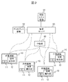
- FIG. It is a figure explaining the structure of the work machine and the repeater of Example 1 in more detail.
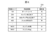
- FIG. It is a figure which shows the example of the data structure of the importance correspondence table in Example 1.
- FIG. It is a figure which shows the example of the data structure of the priority determination table in Example 1.
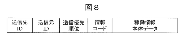
- FIG. It is a figure which shows the packet format example of the operation information used in Example 1.
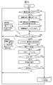
- FIG. It is a flowchart explaining the processing example of the repeater of Example 1.
- FIG. It is a flowchart explaining the processing example of the information controller of Embodiment 2.
- FIG. 1 shows an example of the appearance configuration of the work machine according to the first embodiment of the present invention.
- the work machine 10 of the first embodiment is, for example, a hydraulic excavator, and includes, for example, an upper swivel body 1110, a lower traveling body 1120, a work machine 1130, a swivel mechanism 1140, and a cylinder 1160.
- the upper swivel body 1110 is rotatably attached to the upper part of the lower traveling body 1120 via the swivel mechanism 1140.
- the upper swivel body 1110 is provided with a driver's cab 1111 for the operator to operate.
- the driver's cab 1111 is provided with an operation lever 1112 for the operator to operate the work machine 10.
- the upper swivel body 1110 swivels with respect to the lower traveling body 1120 about a rotation axis parallel to the height direction of the work machine 10.
- the upper swing body 1110 houses, for example, a hydraulic device including an engine and the like.
- the lower traveling body 1120 includes, for example, a track 1121 driven by a hydraulic motor (not shown), and runs the work machine 10 under the control of a control system described later.
- the working machine 1130 is provided, for example, in the front part of the upper swivel body 1110.
- the work machine 1130 is driven by the cylinder 1160 to perform work such as excavation work.
- the working machine 1130 has, for example, a boom 1131, an arm 1132, and a bucket 1133.
- the swivel mechanism 1140 has a hydraulic motor or an electric motor (not shown). The swivel mechanism 1140 swivels the upper swivel body 1110 with respect to the lower traveling body 1120 around a rotation axis parallel to the height direction of the work machine 10 under the control of a control system described later.
- Examples of other work machines are wheel loaders, bulldozers, and dump trucks.
- FIG. 2 is a diagram showing a configuration example of the work machine management system according to the first embodiment.
- the work machine management system is provided, for example, at one work site, but may be provided over a plurality of work sites, or a plurality of work machine management systems may be provided at one work site.
- the work machine management system includes a plurality of work machines 10 and a management server 90.
- a plurality of work machines 10 operate in the same work site.
- the management server 90 collects the operation information of these work machines 10.
- the management server 90 is a computer installed outside the work machine 10, and is installed in, for example, a management center.
- Each work machine 10 stores an identification ID 11 that identifies the work machine. Further, each work machine 10 stores the own vehicle priority 12 (described later).
- the management server 90 can be configured by using, for example, a known computer, and includes, for example, a calculation means, a storage means, an input means, and an output means.
- Arithmetic means include, for example, a processor.
- Storage means include, for example, semiconductor storage media and magnetic disks.
- Input means include, for example, a keyboard and a mouse.
- Output means include, for example, a display device 92 and a printing device.
- the storage means may store the program. By executing this program by the arithmetic means, the management server 90 may realize the functions described in the present specification.
- the management center is located away from the work machine 10, for example.
- the management server 90 and the work machine 10 are connected by long-distance communication (for example, 4th generation mobile communication or satellite communication).
- the work machine management system may include the repeater 80, and the repeater 80 can relay the communication.
- the repeater 80 is installed in the same work site as the work machine 10.
- the repeater 80 is connected to the work machine 10 by, for example, wireless LAN communication according to the IEEE802.11 standard or short-range wireless communication according to the IEEE802.154 standard.
- the repeater 80 may be mounted on the work machine 10 to form a part of the work machine 10, or the work machine 10 may have a function as the repeater 80. In that case, the work machine 10 can transmit and receive data to and from the management server 90 via one or more other work machines 10 by short-range communication.
- the management server 90 stores failure risk information 91 for the work machine 10 (for example, all applicable work machines 10) operating at the work site.
- FIG. 3 shows an example of failure risk information 91.
- FIG. 3A shows a configuration example of the failure risk information 91.
- the failure risk information 91 is configured as a table in which failure risk information is registered for each identification ID (corresponding to the identification ID 11 in FIG. 2) of the work machine 10.
- Each record of the failure risk information 91 includes fields of failure possibility, work importance, presence / absence of alternative machine, risk assessment value, and vehicle body priority.
- the possibility of failure represents the possibility of failure of the work machine 10, and is represented by, for example, three stages of large, medium, and small.
- the possibility of failure can be determined by the manager of the work site based on the total operating time of the work machine 10, the past failure history, and the like.
- the work importance represents the importance of the work machine 10 in the field work. For example, it indicates how important the process carried out by the work machine is in the work plan at the work site. Work importance is expressed in three stages, for example, large, medium, and small. The work importance can be determined by the manager based on the margin of the schedule of the process in which the work machine 10 is involved, the relationship with the post-process, and the like.
- the presence or absence of a substitute machine is an example of information indicating the possibility that the work machine 10 can be replaced by another work machine 10. For example, if a spare machine that can be used as a substitute for the work machine 10 is prepared at the work site or an agency, the presence or absence of the substitute machine is "Yes", and if not, "No". The administrator can decide whether or not there is an alternative machine.
- the administrator at the work site inputs the above setting values of the fields of possibility of failure, work importance, and presence / absence of an alternative machine to the management server 90.
- the management server 90 stores the input information as failure risk information 91.
- FIG. 3B is an example of an input interface screen for inputting information used for determining the vehicle body priority (for example, failure possibility, work importance, and presence / absence of alternative machine).
- the vehicle body priority for example, failure possibility, work importance, and presence / absence of alternative machine.
- "?" Is displayed as to whether or not there is an alternative machine, and the input of the presence or absence of the substitute machine is prompted.
- the risk assessment value in FIG. 3A is a value that comprehensively evaluates the possibility of failure, the importance of work, and the presence or absence of an alternative machine.
- 30 points are given for large, 20 points are given for medium, and 10 points are given for small.
- 10 points are given for small.
- yes is 0 points and no is 10 points.
- the management server 90 calculates the risk assessment value of each work machine 10 by summing these points.
- the vehicle body priority represents the priority among the work machines, for example, for each work machine, the priority between the other one or more work machines.
- the management server 90 determines the vehicle body priority as, for example, the order in which the risk assessment values are arranged in descending order.
- the vehicle body priority determined as described above is distributed from the management server 90 to each work machine 10 as management server information via a long-distance radio or a repeater 80.
- Each work machine 10 receives the management server information, and stores the vehicle body priority included in the management server information as the own vehicle priority 12 (FIG. 2).
- Failure risk information may be generated by other methods. For example, the failure possibility, work importance, and presence / absence of alternative machine fields are automatically determined by the management server 90 via communication with other computers (body management system, work planning system, agency system, etc.). You may try to do it. Further, the risk assessment value may be added after multiplying each item by a coefficient indicating how much each item is emphasized, instead of simply adding.
- the vehicle body priority may be expressed as a deviation value considering the distribution of risk assessment values instead of a simple ranking. Further, when determining the vehicle body priority, it is not necessary to refer to all the information shown in FIG. 3A.
- the management server 90 can determine the vehicle body priority based on at least one of failure possibility, work importance, and presence / absence of an alternative machine. Further, in that case, the input interface screen of FIG. 3B is used to input at least one of the possibility of failure, the importance of work, and the presence / absence of an alternative machine.
- the work machine 10 includes a controller as a control system according to the present embodiment.
- the controller includes an information controller 20, an engine controller 30, a vehicle body controller 40, and a communication controller 50.
- the information controller 20, the engine controller 30, the vehicle body controller 40, and the communication controller 50 are connected to each other via the vehicle body network 60.
- the information controller 20 can be configured by using, for example, a known computer, and includes, for example, a calculation means and a storage means.
- Arithmetic means include, for example, a processor.
- Storage means include, for example, semiconductor storage media and / or magnetic disks. The storage means may store the program.
- the information controller 20 may realize the functions described in the present specification by executing this program by the arithmetic means.
- the engine controller 30, the vehicle body controller 40, and the communication controller 50 can also be configured by using a known computer in the same manner. Two or more of the information controller 20, the engine controller 30, the vehicle body controller 40, and the communication controller 50 may be realized by one computer, or the information controller 20 may be realized by two or more computers.
- the information controller 20 acquires the operation information (first operation information) of the work machine 10.
- the operation information is detected by, for example, the engine controller 30 and the vehicle body controller 40 and transmitted via the vehicle body network 60, and the information controller 20 receives and acquires the operation information.
- the information controller 20 transmits the acquired operation information to the management server 90 via the communication controller 50 at predetermined time intervals (for example, once a day or once an hour).
- the engine controller 30 controls the electronic governor provided in the engine.
- the engine controller 30 includes various sensors 31 such as an engine actual rotation speed sensor.
- the engine controller 30 acquires detection signals from various sensors 31.
- the engine controller 30 controls the fuel injection amount.
- the engine controller 30 outputs a command signal to each device 32 such as an electronic governor in order to control the engine speed and the output torque.
- the vehicle body controller 40 controls the hydraulic drive device of the work machine 10.
- the hydraulic drive system includes, for example, the following hydraulic devices as its components. -Hydraulic pump that is rotationally driven by the engine-Multiple hydraulic actuators that are driven by the hydraulic oil discharged from the hydraulic pump and drive the driven body such as the working machine 1130-The hydraulic oil supplied from the hydraulic pump to the hydraulic actuator Control valve to control the flow-Operating lever 1112 to operate the control valve and drive the corresponding hydraulic actuator (Fig. 1)
- the hydraulic actuator includes, for example, a boom hydraulic cylinder, an arm hydraulic cylinder, and a bucket hydraulic cylinder for driving the boom 1131, arm 1132, and bucket 1133 in FIG. 1, respectively. Further, the hydraulic actuator includes a traveling hydraulic motor for traveling the lower traveling body 1120, a turning hydraulic motor for turning the upper turning body 1110, and the like.
- the vehicle body controller 40 acquires detection signals from various sensors 41 such as a detection sensor that detects the operation amount of the operation lever 1112, for example.
- the vehicle body controller 40 controls the tilt angle (capacity) of the hydraulic pump and outputs a command signal to each device 42 such as a regulator so as to discharge a flow rate according to the operation amount thereof.
- the communication controller 50 controls transmission / reception with the management server 90 via the long-distance communication device 51. Further, the communication controller 50 controls transmission / reception with the repeater 80 via the short-range communication device 52.
- the communication controller 50 receives the position information and the time information from the GPS satellites via the GPS antenna 53.
- the repeater 80 receives the information transmitted from the work machine 10 via the short-distance communication device 82, relays the information, and transmits the information to the management server 90 via the long-distance communication device 81.
- the information controller 20 has monitoring unit 201, buffer unit 202, operation information importance determination unit 203, importance correspondence table 204, own vehicle priority 12 (own vehicle body priority), and transmission data priority as functional blocks. It includes a ranking determination table 206, a transmission data priority determination unit 207, an information transmission / reception unit 208, an internal clock 209, and the like. The information controller 20 can function as these functional blocks.
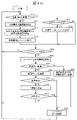
- FIG. 5 is a flowchart illustrating a processing example of the information controller 20.
- the monitoring unit 201 receives operation information from the engine controller 30 and the vehicle body controller 40 via the vehicle body network 60.
- the operation information represents, for example, the operation status of the work machine 10.
- Examples of various sensors 31 and 41 include a key signal sensor, an overheat signal sensor, an engine hydraulic sensor, an engine actual rotation speed sensor, a water temperature sensor, an air filter differential pressure sensor, a main hydraulic pump pressure sensor, and the like.
- operation information information representing at least one of a key signal, an overheat signal, an engine hydraulic pressure, an engine actual rotation speed, a water temperature, an air filter differential pressure, a main hydraulic pump pressure, and the like can be used.
- the overheat signal sensor detects an overheat signal transmitted when the engine cooling water temperature reaches a set value or higher.
- the engine oil pressure sensor detects an abnormality in the engine oil circulation system by detecting the engine oil pressure. For example, when the engine oil pressure is equal to or less than a predetermined threshold value, it is detected that an abnormality such as an oil leak has occurred in the engine oil circulation system.
- the importance determination unit 203 determines the importance of the operation information in step 502. The judgment is made using the importance correspondence table. This will be described with reference to FIG.
- FIG. 6 is an example of the data structure of the importance correspondence table 204.
- Each record corresponds to one of the types of operation information.
- Each record includes a field of an information code indicating the type of operation information, an information type indicating the name (character string) of the type of operation information, and an importance indicating the importance of the operation information.
- the importance determination unit 203 determines the importance of the operation information by identifying the type of the acquired operation information based on the information code.
- the importance is shown in three stages of large, medium, and small, but the importance is not limited to this.
- step 503 the priority determination unit 207 determines the priority for processing the operation information.
- the vehicle priority 12 and the priority decision table are used. This will be described with reference to FIG.
- FIG. 7 is an example of the data structure of the priority determination table 206.
- the priority decision table 206 is represented as a matrix.
- the vertical axis represents the vehicle body priority and the horizontal axis represents the importance of operation information.
- FIG. 7 shows three cases where the importance of the operation information is high, medium, and low for each of the vehicle body priorities 1 to 4 (1 is high and 4 is low). Indicates the transmission priority.
- the transmission priority for that combination is described at the corresponding position in the matrix, and the smaller the value, the higher the priority.
- the transmission priority is set to be low. For example, when the vehicle body priority is 4 (lowest), the transmission priority is 9 even if the importance of the operation information is high (highest), so the vehicle body priority is 1 (highest) and the priority of the operation information is 1.
- the transmission priority is lower than the small (lowest) transmission priority 4.
- the priority determination unit 207 determines the transmission priority of the operation information based on the content (that is, the type) of the operation information and the management server information (for example, the vehicle body priority included in the management server information). ..
- step 504 the contents of the operation information are stored in the buffer unit 202 together with the transmission priority determined above and the time of the internal clock 209.
- the time of the internal clock 209 may be corrected by the time information from the GPS received by the communication controller 50.
- step 505 it is determined whether or not the operation information stored in the buffer unit 202 exists. If the operation information is not stored in the buffer unit 202, the process returns to step 501 and waits for the operation information to be received. On the other hand, when the operation information is stored in the buffer unit 202, the operation information having the highest transmission priority is acquired from the buffer unit 202 in step 506.
- step 507 the resending condition of the acquired operation information may be confirmed. If the retransmission condition is not satisfied (step 507: YES. For example, if the predetermined number of retransmissions is exceeded or the predetermined retransmission timeout time has passed), transmission may fail and the process may proceed to step 512. ..
- step 507 when the retransmission condition is satisfied (step 507: NO), the information transmission / reception unit 208 transmits the operation information to the management server via the communication controller 50 in step 508. Long-distance communication is used for communication here.
- the information controller 20 may determine the retransmission condition according to the transmission priority. For example, at least one of the retransmission interval of the operation information, the number of times of retransmission of the operation information, and the retransmission timeout value of the operation information may be determined according to the transmission priority.
- the retransmission interval is short, for example, 1 second, and when the transmission priority is low, the retransmission interval is long, for example, 10 seconds.
- the transmission priority is high, the number of retransmissions is large, for example, 10 times, and when the transmission priority is low, the number of retransmissions is small, for example, 3 times.
- the retransmission timeout is long, for example, 10 minutes, and when the transmission priority is low, the retransmission timeout is short, for example, 1 minute.
- step 509 the success or failure of the communication in step 508 is confirmed, and if successful, the process proceeds to step 512.
- the communication fails, the information transmission / reception unit 208 transmits the operation information to the repeater 80 via the communication controller 50 in step 510.
- Short-range communication is used for communication here.
- step 511 the success or failure of the communication in step 510 is confirmed. The success or failure can be confirmed, for example, to the management server 90. This confirmation process may be relayed by the repeater 80. If the communication is successful, the process proceeds to step 512, the operation information is deleted from the buffer unit 202, and then the process returns to step 501.
- step 511 the number of retransmissions of the operation information in the buffer unit 202 is increased by 1, and then the process returns to step 501.
- the information controller 20 transmits operation information according to the transmission priority.
- the transmission priority is associated with the operation information and transmitted. This will be described with reference to FIG.
- FIG. 8 is an example of the packet format of the operation information used in the first embodiment.
- This packet format is used, for example, in short-range communication.
- the packet includes a destination ID, a source ID, a transmission priority, an information code, and operation information body data.
- the destination ID is the identification information of the management server 90, which is the original destination of the operation information, and is, for example, its IP address.
- the source ID is the identification ID 11 of the work machine 10 that created this packet.
- the repeater 80 can know which packet should be preferentially processed from the plurality of received packets by referring to the transmission priority field.
- the information code corresponds to the information code in FIG.
- the operation information main body data includes the operation information itself to be transmitted to the management server 90.
- the information controller 20 may determine the transmission interval or transmission amount of the operation information according to the transmission priority.
- the transmission interval means, for example, the time interval in which step 505 of FIG. 5 is executed. For example, for operation information with a high transmission priority, step 505 is executed more frequently.
- the transmission amount means the amount of operation information transmitted in one transmission process, and is expressed in bits or bytes, for example.
- the unit of the number of transmission processes can be appropriately defined by those skilled in the art, but for example, the process of transmitting one packet shown in FIG. 8 corresponds to one transmission process.
- the transmission priority when the transmission priority is high, the entire operation information is transmitted, and when the transmission priority is low, only a part of the operation information is transmitted and the other parts are discarded. For example, an unimportant part (for example, the least significant bit) of the operation information may be omitted, or the operation information acquired every minute may be transmitted and acquired at another timing. You may discard what has been done.
- FIG. 9 is a flowchart illustrating a processing example of the repeater 80 of the first embodiment.
- step 901 the operation information sent from the surrounding work machines 10 is received by short-range communication.
- the operation information is stored in the internal buffer in step 902. If the operation information is not received, the process returns to step 901 and waits for reception.
- step 903 it is confirmed whether the operation information stored in the buffer exists. If the buffer is empty, the process returns to step 901 and waits for reception. If the operation information exists in the buffer, the operation information having the highest transmission priority is acquired from the buffer in step 904.
- step 905 the conditions for resending the acquired operation information are confirmed. If the retransmission condition is not satisfied (step 905: YES. For example, if the predetermined number of retransmissions is exceeded or the predetermined retransmission timeout time has passed), transmission fails and the process proceeds to step 906. .. In step 906, the operation information (more strictly, the corresponding packet) is deleted from the buffer, and in step 907, the transmission failure is transmitted to the relay requesting machine 10 as a transmission result.
- step 905 if the retransmission condition is satisfied (step 905: NO), the operation information is transmitted to the management server in step 908. Long-distance communication is used for communication here.
- step 909 the success or failure of the communication in step 908 is confirmed, and if successful, the process proceeds to step 910.
- step 910 the process returns to step 903 after deleting the corresponding operation information from the buffer.
- the transmission success may be transmitted to the relay requesting work machine 10 as a transmission result.
- step 909 if the communication fails in step 909, the number of retransmissions of the operation information is increased by 1, and then the process returns to step 901.
- the operation information of the work machine having a high failure risk is prioritized over the work machine having a low failure risk, so that the operation information reaches the management server 90 more reliably.
- the manager can grasp and deal with the abnormality of the work machine having a high risk of failure at an early stage.
- the work machine 10 and the work machine management system according to the first embodiment even when the number of work machines 10 is large, the information of the work machine 10 having a high priority is transmitted more appropriately. Can be done.
- the management server information includes the vehicle body priority, it is not necessary for the work machines 10 to determine their own vehicle body priorities, and the configuration of the information controller 20 is simplified.
- the management server 90 determines the vehicle body priority based on the possibility of failure, work importance, presence / absence of an alternative machine, etc., so that the vehicle body priority is determined in consideration of various factors. Can be done.
- each work machine 10 independently determines its own vehicle body priority. This makes it possible to simplify the configuration of the management server 90.
- the management server 90 since the management server 90 outputs the input interface screen of FIG. 3B to the display device 92, it is easy to input the possibility of failure, the importance of work, the presence or absence of an alternative device, and the like.
- the operation information having a higher transmission priority is retransmitted more frequently. You can try.
- the operation information having a high transmission priority can be transmitted more quickly, or , Operation information with high transmission priority can be transmitted without reducing the amount of information.
- FIG. 10 is a flowchart illustrating a processing example of the information controller 20 of the second embodiment.
- the working machine 10 also operates as the repeater 80 in the first embodiment.
- the overall configuration of the work machine management system and the configuration of the work machine 10 are omitted because they are the same as those described in the first embodiment (FIGS. 2 and 4). Further, also in the flowchart of FIG. 10, the same reference numerals may be given to the portions common to the flowchart of FIG. 5 of the first embodiment, and duplicate description may be omitted.
- step 601 the information transmission / reception unit 208 receives the operation information (second operation information) sent from another work machine 10 as relay data via the communication controller 50. Short-range communication is used for this communication. If the operation information is not received in step 601 the process proceeds to step 505.
- the second operation information is received in step 601 the second operation information is stored in the buffer unit 202 in step 602.
- the packet of the second operation information received shows the transmission priority as shown in FIG. That is, the information controller 20 can receive the second operation information and the transmission priority of the second operation information from another work machine.
- step 602 data in the same format as the first operation information stored in step 504 is stored. Therefore, in the following steps 505 to 511, by performing the same processing as in the first embodiment, the operation information (first operation information) of the work machine 10 on which the information controller 20 is mounted and the operation information to be relayed (first operation information) are performed.
- the second operation information) is treated in the same manner, and the high-priority data is acquired in step 506 and transmitted in step 508. That is, the information controller 20 gives priority to the higher transmission priority of the first operation information and the second operation information based on the transmission priority of the first operation information and the transmission priority of the second operation information. Send.
- step 507 transmission failure
- the result to that effect is transmitted to the requesting work machine 10 in step 603, and the process proceeds to step 512. Further, even if the transmission is successful in step 509 and step 511, the process proceeds to step 512.
- the work machine 10 itself can function as a repeater to expand the communication range. Even in that case, the operation information of the work machine having a high failure risk is prioritized over the work machine having a low failure risk, so that the operation information reaches the management server 90 more reliably. As a result, the manager can grasp and deal with the abnormality of the work machine having a high risk of failure at an early stage.
- Example 1 Further, with respect to other effects, the same effects as in Example 1 can be obtained.
- a person skilled in the art can appropriately determine a method for selecting a plurality of work machines 10 that operate as a repeater 80.
- the management server for example, one that has a long-distance communication function
- one that has a track record of operating as a repeater, and the like can be configured to be selected.
- the plurality of work machines 10 may function as the repeater 80 to realize communication by the bucket brigade method.
- Example 1 or 2 in addition to the above-mentioned modification, the following modification is also possible.
- the management server 90 transmits the vehicle body priority to each work machine 10 as a part of the management server information.
- the vehicle body priority may be determined by each work machine 10.
- the management server 90 may transmit information for determining the vehicle body priority to each work machine 10.
- the management server 90 may transmit at least one of failure possibility, work importance, and presence / absence of an alternative machine to each work machine 10 as management server information. Further, each work machine 10 may determine the transmission priority of the operation information based on the content of the operation information and the received management server information. The specific determination is made, for example, by the method described with reference to FIG. 3A in Example 1.
Landscapes
- Engineering & Computer Science (AREA)
- Physics & Mathematics (AREA)
- General Physics & Mathematics (AREA)
- Automation & Control Theory (AREA)
- Mining & Mineral Resources (AREA)
- Civil Engineering (AREA)
- General Engineering & Computer Science (AREA)
- Structural Engineering (AREA)
- Operation Control Of Excavators (AREA)
- Testing And Monitoring For Control Systems (AREA)
- Management, Administration, Business Operations System, And Electronic Commerce (AREA)
Abstract
Description
作業機械の第1稼働情報を取得し、前記作業機械の外部に設けた管理サーバから管理サーバ情報を受信するコントローラを備えた作業機械において、
前記第1稼働情報は、キー信号、オーバーヒート信号、エンジン油圧、エンジン実回転数、水温、エアフィルタ差圧、メイン油圧ポンプ圧、のうち少なくとも1つを表す情報を含み、
前記管理サーバ情報は、前記作業機械と別の作業機械との間の優先順位を表す車体優先度と、前記作業機械の故障可能性、現場作業における前記作業機械の重要度、前記作業機械が別の作業機械によって代替され得る可能性、のうち少なくとも1つと、を含み、
前記コントローラは、
前記第1稼働情報の内容と、前記管理サーバ情報とに基づき、前記第1稼働情報の送信優先順位を決定し、
前記送信優先順位に従って、前記管理サーバまたは中継器に前記第1稼働情報を送信することを特徴とする。
上述の作業機械と、前記管理サーバとを備える、作業機械管理システムにおいて、
前記管理サーバは、前記作業機械の故障可能性、現場作業における前記作業機械の重要度、前記作業機械が別の作業機械によって代替され得る可能性、のうち少なくとも1つに基づいて、前記車体優先度を決定する、
ことを特徴とする。
本明細書は本願の優先権の基礎となる日本国特許出願番号2020-184244号の開示内容を包含する。
‐エンジンにより回転駆動される油圧ポンプ
‐油圧ポンプから吐出された圧油により駆動され、作業機1130等の被駆動体を駆動する複数の油圧アクチュエータ
‐油圧ポンプから油圧アクチュエータに供給される圧油の流れを制御するコントロールバルブ
‐コントロールバルブを操作し対応する油圧アクチュエータを駆動する操作レバー1112(図1)
実施例1または2においては、上述の変形例に加え、以下のような変形例も可能である。
本明細書で引用した全ての刊行物、特許および特許出願はそのまま引用により本明細書に組み入れられるものとする。
Claims (7)
- 作業機械の第1稼働情報を取得し、前記作業機械の外部に設けた管理サーバから管理サーバ情報を受信するコントローラを備えた作業機械において、
前記第1稼働情報は、キー信号、オーバーヒート信号、エンジン油圧、エンジン実回転数、水温、エアフィルタ差圧、メイン油圧ポンプ圧、のうち少なくとも1つを表す情報を含み、
前記管理サーバ情報は、前記作業機械と別の作業機械との間の優先順位を表す車体優先度と、前記作業機械の故障可能性、現場作業における前記作業機械の重要度、前記作業機械が別の作業機械によって代替され得る可能性、のうち少なくとも1つと、を含み、
前記コントローラは、
前記第1稼働情報の内容と、前記管理サーバ情報とに基づき、前記第1稼働情報の送信優先順位を決定し、
前記送信優先順位に従って、前記管理サーバまたは中継器に前記第1稼働情報を送信することを特徴とする作業機械。 - 前記コントローラは、前記送信優先順位を前記第1稼働情報に関連付けて送信することを特徴とする請求項1に記載の作業機械。
- 前記コントローラは、前記送信優先順位に応じて、前記第1稼働情報の再送間隔、前記第1稼働情報の再送回数、前記第1稼働情報の再送タイムアウト値、のうち少なくとも一つを決定することを特徴とする請求項1に記載の作業機械。
- 前記コントローラは、前記送信優先順位に応じて、
‐前記第1稼働情報の送信間隔、または、
‐1回の送信処理において送信される前記第1稼働情報の量
を決定することを特徴とする請求項1に記載の作業機械。 - 前記コントローラは、
別の作業機械から、第2稼働情報と、前記第2稼働情報の送信優先順位とを受信し、
前記第1稼働情報の前記送信優先順位と、前記第2稼働情報の前記送信優先順位とに基づき、前記第1稼働情報および前記第2稼働情報のうち送信優先順位の高い方を優先して、前記管理サーバまたは前記中継器に送信し、
前記第2稼働情報は、キー信号、オーバーヒート信号、エンジン油圧、エンジン実回転数、水温、エアフィルタ差圧、メイン油圧ポンプ圧、のうち少なくとも1つを表す情報を含む
ことを特徴とする請求項2に記載の作業機械。 - 請求項1に記載の作業機械と、前記管理サーバとを備える、作業機械管理システムにおいて、
前記管理サーバは、前記作業機械の故障可能性、現場作業における前記作業機械の重要度、前記作業機械が別の作業機械によって代替され得る可能性、のうち少なくとも1つに基づいて、前記車体優先度を決定する、
ことを特徴とする作業機械管理システム。 - 前記管理サーバは、前記車体優先度を決定するために用いられる情報を入力するための入力インタフェース画面を、ディスプレイ装置に出力することを特徴とする請求項6に記載の作業機械管理システム。
Priority Applications (4)
| Application Number | Priority Date | Filing Date | Title |
|---|---|---|---|
| US18/023,504 US12585264B2 (en) | 2020-11-04 | 2021-10-22 | Work machine and work machine management system transmitting information according to priority |
| CN202180052660.2A CN115989466A (zh) | 2020-11-04 | 2021-10-22 | 作业机械以及作业机械管理系统 |
| EP21889060.6A EP4242384B1 (en) | 2020-11-04 | 2021-10-22 | Work machine and work machine management system |
| KR1020237006436A KR102695775B1 (ko) | 2020-11-04 | 2021-10-22 | 작업 기계 및 작업 기계 관리 시스템 |
Applications Claiming Priority (2)
| Application Number | Priority Date | Filing Date | Title |
|---|---|---|---|
| JP2020184244A JP7352532B2 (ja) | 2020-11-04 | 2020-11-04 | 作業機械および作業機械管理システム |
| JP2020-184244 | 2020-11-04 |
Publications (1)
| Publication Number | Publication Date |
|---|---|
| WO2022097507A1 true WO2022097507A1 (ja) | 2022-05-12 |
Family
ID=81457802
Family Applications (1)
| Application Number | Title | Priority Date | Filing Date |
|---|---|---|---|
| PCT/JP2021/039161 Ceased WO2022097507A1 (ja) | 2020-11-04 | 2021-10-22 | 作業機械および作業機械管理システム |
Country Status (6)
| Country | Link |
|---|---|
| US (1) | US12585264B2 (ja) |
| EP (1) | EP4242384B1 (ja) |
| JP (1) | JP7352532B2 (ja) |
| KR (1) | KR102695775B1 (ja) |
| CN (1) | CN115989466A (ja) |
| WO (1) | WO2022097507A1 (ja) |
Families Citing this family (2)
| Publication number | Priority date | Publication date | Assignee | Title |
|---|---|---|---|---|
| JP2024089387A (ja) * | 2022-12-21 | 2024-07-03 | 住友重機械工業株式会社 | ショベルの管理システム、ショベルの管理装置 |
| CN116588122B (zh) * | 2023-07-17 | 2023-10-20 | 山东港口工程管理咨询有限公司 | 一种基于远程控制车辆的漏油监测方法、设备及介质 |
Citations (8)
| Publication number | Priority date | Publication date | Assignee | Title |
|---|---|---|---|---|
| JP2002180502A (ja) * | 2000-09-20 | 2002-06-26 | Komatsu Ltd | 作業機械の管理装置および作業機械の通信装置 |
| JP2011070397A (ja) | 2009-09-25 | 2011-04-07 | Hitachi Constr Mach Co Ltd | 機械の異常監視装置 |
| JP2011221813A (ja) * | 2010-04-09 | 2011-11-04 | Denso Corp | 車両診断システム |
| JP2012160085A (ja) * | 2011-02-01 | 2012-08-23 | Komatsu Ltd | 建設機械のメンテナンス方法およびメンテナンスシステム |
| JP2013194440A (ja) * | 2012-03-21 | 2013-09-30 | Caterpillar Sarl | 作業機の遠隔操縦装置 |
| US20190066005A1 (en) * | 2017-08-28 | 2019-02-28 | Deere & Company | Methods and apparatus to monitor work vehicles and to generate worklists to order the repair of such work vehicles should a machine failure be identified |
| JP2019175360A (ja) * | 2018-03-29 | 2019-10-10 | 株式会社小松製作所 | 作業機械の情報管理装置、情報管理方法及び情報管理システム |
| JP2020184244A (ja) | 2019-05-09 | 2020-11-12 | 株式会社ニコン・エシロール | ウェアラブル端末装置、認証システム、制御方法、及びプログラム |
Family Cites Families (13)
| Publication number | Priority date | Publication date | Assignee | Title |
|---|---|---|---|---|
| JP2002188183A (ja) * | 2000-10-12 | 2002-07-05 | Komatsu Ltd | 作機機械の管理装置 |
| US20050002354A1 (en) * | 2003-07-02 | 2005-01-06 | Kelly Thomas J. | Systems and methods for providing network communications between work machines |
| WO2006085469A1 (ja) * | 2005-02-14 | 2006-08-17 | Komatsu Ltd. | 作業機械の不具合情報集中管理システム |
| US8756331B2 (en) * | 2005-12-20 | 2014-06-17 | Caterpillar Inc. | QOS-based communications on a work machine |
| JP5334010B2 (ja) * | 2008-03-10 | 2013-11-06 | 東芝エレベータ株式会社 | 昇降機保守管理装置 |
| CN110067278A (zh) * | 2011-09-30 | 2019-07-30 | 住友重机械工业株式会社 | 挖土机、挖土机管理装置及挖土机信息系统 |
| JP6059039B2 (ja) * | 2013-02-26 | 2017-01-11 | 京セラ株式会社 | 送信装置及び送信方法 |
| JP6029553B2 (ja) * | 2013-08-22 | 2016-11-24 | 日立オートモティブシステムズ株式会社 | 車両制御装置 |
| JP6302645B2 (ja) | 2013-11-12 | 2018-03-28 | 日立建機株式会社 | 作業機械の稼働データ収集装置 |
| US9773352B2 (en) * | 2013-11-19 | 2017-09-26 | Komatsu Ltd. | Work machine and work machine management system |
| JP6392251B2 (ja) * | 2014-01-21 | 2018-09-19 | 住友重機械工業株式会社 | ショベルの管理装置、及び支援装置 |
| US9982414B2 (en) * | 2016-05-16 | 2018-05-29 | Caterpillar Inc. | Operation identification of a work machine |
| JP7052218B2 (ja) | 2017-05-19 | 2022-04-12 | コニカミノルタ株式会社 | エッジコンピューティングシステム、通信制御方法及び通信制御プログラム |
-
2020
- 2020-11-04 JP JP2020184244A patent/JP7352532B2/ja active Active
-
2021
- 2021-10-22 US US18/023,504 patent/US12585264B2/en active Active
- 2021-10-22 CN CN202180052660.2A patent/CN115989466A/zh active Pending
- 2021-10-22 WO PCT/JP2021/039161 patent/WO2022097507A1/ja not_active Ceased
- 2021-10-22 EP EP21889060.6A patent/EP4242384B1/en active Active
- 2021-10-22 KR KR1020237006436A patent/KR102695775B1/ko active Active
Patent Citations (8)
| Publication number | Priority date | Publication date | Assignee | Title |
|---|---|---|---|---|
| JP2002180502A (ja) * | 2000-09-20 | 2002-06-26 | Komatsu Ltd | 作業機械の管理装置および作業機械の通信装置 |
| JP2011070397A (ja) | 2009-09-25 | 2011-04-07 | Hitachi Constr Mach Co Ltd | 機械の異常監視装置 |
| JP2011221813A (ja) * | 2010-04-09 | 2011-11-04 | Denso Corp | 車両診断システム |
| JP2012160085A (ja) * | 2011-02-01 | 2012-08-23 | Komatsu Ltd | 建設機械のメンテナンス方法およびメンテナンスシステム |
| JP2013194440A (ja) * | 2012-03-21 | 2013-09-30 | Caterpillar Sarl | 作業機の遠隔操縦装置 |
| US20190066005A1 (en) * | 2017-08-28 | 2019-02-28 | Deere & Company | Methods and apparatus to monitor work vehicles and to generate worklists to order the repair of such work vehicles should a machine failure be identified |
| JP2019175360A (ja) * | 2018-03-29 | 2019-10-10 | 株式会社小松製作所 | 作業機械の情報管理装置、情報管理方法及び情報管理システム |
| JP2020184244A (ja) | 2019-05-09 | 2020-11-12 | 株式会社ニコン・エシロール | ウェアラブル端末装置、認証システム、制御方法、及びプログラム |
Non-Patent Citations (1)
| Title |
|---|
| See also references of EP4242384A4 |
Also Published As
| Publication number | Publication date |
|---|---|
| JP2022074305A (ja) | 2022-05-18 |
| EP4242384A1 (en) | 2023-09-13 |
| KR20230042104A (ko) | 2023-03-27 |
| EP4242384B1 (en) | 2025-12-10 |
| US12585264B2 (en) | 2026-03-24 |
| CN115989466A (zh) | 2023-04-18 |
| EP4242384A4 (en) | 2024-10-23 |
| JP7352532B2 (ja) | 2023-09-28 |
| KR102695775B1 (ko) | 2024-08-19 |
| US20230315080A1 (en) | 2023-10-05 |
Similar Documents
| Publication | Publication Date | Title |
|---|---|---|
| JP3366837B2 (ja) | 機械の異常監視装置および方法 | |
| US7676804B2 (en) | Systems and method for remotely modifying software on a work machine | |
| JP6302645B2 (ja) | 作業機械の稼働データ収集装置 | |
| US7711842B2 (en) | System and method for remote machine data transfer | |
| US7050893B2 (en) | Method of detection of actual operating time of machinery deployed at construction sites, data collection and management system, and base station | |
| US12078493B2 (en) | Worksite management system | |
| US20140288675A1 (en) | Diagnostic Processing System, Onboard Terminal System, and Server | |
| JP7352532B2 (ja) | 作業機械および作業機械管理システム | |
| EP4317600B1 (en) | Work machine | |
| WO2009074066A1 (en) | A system and method for locating and monitoring machine and a device for realizing communication | |
| US7987027B2 (en) | Systems for processing machine health information | |
| CN111492623A (zh) | 用于控制开采和/或施工机器的通信的方法和系统 | |
| WO2001091350A2 (en) | System and method for performing remote security management of client computer systems | |
| KR20020019954A (ko) | 작업기계의 통신시스템 | |
| US20250123832A1 (en) | Software updating system, working machine, and software updating method | |
| JP4559669B2 (ja) | 作業機械の制御装置 | |
| CN104798354A (zh) | 作业机械及作业机械的管理系统 | |
| CN104106090B (zh) | 提供当前可作业信息的工程机械的故障管理方法 | |
| AU2021316171A1 (en) | System and method for tracking activity of a plurality of machines | |
| EP1439466B1 (en) | Communication server switching controller | |
| EP1826727A2 (en) | System for automatic authorization and notification of transmitted data | |
| US12627526B2 (en) | Gateway device with a routing function | |
| CN114761954A (zh) | 篡改对象设备确定系统、确定程序以及确定方法 | |
| JP2005009124A (ja) | 掘削機の遠隔監視、制御装置 | |
| CN210864361U (zh) | 一种施工设备的监管装置 |
Legal Events
| Date | Code | Title | Description |
|---|---|---|---|
| 121 | Ep: the epo has been informed by wipo that ep was designated in this application |
Ref document number: 21889060 Country of ref document: EP Kind code of ref document: A1 |
|
| ENP | Entry into the national phase |
Ref document number: 20237006436 Country of ref document: KR Kind code of ref document: A |
|
| NENP | Non-entry into the national phase |
Ref country code: DE |
|
| ENP | Entry into the national phase |
Ref document number: 2021889060 Country of ref document: EP Effective date: 20230605 |
|
| WWG | Wipo information: grant in national office |
Ref document number: 2021889060 Country of ref document: EP |
|
| WWG | Wipo information: grant in national office |
Ref document number: 18023504 Country of ref document: US |