WO2022097581A1 - アンテナセット - Google Patents
アンテナセット Download PDFInfo
- Publication number
- WO2022097581A1 WO2022097581A1 PCT/JP2021/040092 JP2021040092W WO2022097581A1 WO 2022097581 A1 WO2022097581 A1 WO 2022097581A1 JP 2021040092 W JP2021040092 W JP 2021040092W WO 2022097581 A1 WO2022097581 A1 WO 2022097581A1
- Authority
- WO
- WIPO (PCT)
- Prior art keywords
- antenna
- antenna units
- antenna unit
- degrees
- units
- Prior art date
- Legal status (The legal status is an assumption and is not a legal conclusion. Google has not performed a legal analysis and makes no representation as to the accuracy of the status listed.)
- Ceased
Links
Images







Classifications
-
- H—ELECTRICITY
- H01—ELECTRIC ELEMENTS
- H01Q—ANTENNAS, i.e. RADIO AERIALS
- H01Q21/00—Antenna arrays or systems
- H01Q21/28—Combinations of substantially independent non-interacting antenna units or systems
-
- H—ELECTRICITY
- H01—ELECTRIC ELEMENTS
- H01Q—ANTENNAS, i.e. RADIO AERIALS
- H01Q1/00—Details of, or arrangements associated with, antennas
- H01Q1/12—Supports; Mounting means
- H01Q1/1242—Rigid masts specially adapted for supporting an aerial
-
- H—ELECTRICITY
- H01—ELECTRIC ELEMENTS
- H01Q—ANTENNAS, i.e. RADIO AERIALS
- H01Q1/00—Details of, or arrangements associated with, antennas
- H01Q1/12—Supports; Mounting means
- H01Q1/22—Supports; Mounting means by structural association with other equipment or articles
- H01Q1/24—Supports; Mounting means by structural association with other equipment or articles with receiving set
- H01Q1/241—Supports; Mounting means by structural association with other equipment or articles with receiving set used in mobile communications, e.g. GSM
- H01Q1/246—Supports; Mounting means by structural association with other equipment or articles with receiving set used in mobile communications, e.g. GSM specially adapted for base stations
-
- H—ELECTRICITY
- H01—ELECTRIC ELEMENTS
- H01Q—ANTENNAS, i.e. RADIO AERIALS
- H01Q21/00—Antenna arrays or systems
- H01Q21/06—Arrays of individually energised antenna units similarly polarised and spaced apart
- H01Q21/08—Arrays of individually energised antenna units similarly polarised and spaced apart the units being spaced along or adjacent to a rectilinear path
-
- H—ELECTRICITY
- H01—ELECTRIC ELEMENTS
- H01Q—ANTENNAS, i.e. RADIO AERIALS
- H01Q21/00—Antenna arrays or systems
- H01Q21/06—Arrays of individually energised antenna units similarly polarised and spaced apart
- H01Q21/20—Arrays of individually energised antenna units similarly polarised and spaced apart the units being spaced along or adjacent to a curvilinear path
- H01Q21/205—Arrays of individually energised antenna units similarly polarised and spaced apart the units being spaced along or adjacent to a curvilinear path providing an omnidirectional coverage
-
- H—ELECTRICITY
- H01—ELECTRIC ELEMENTS
- H01Q—ANTENNAS, i.e. RADIO AERIALS
- H01Q3/00—Arrangements for changing or varying the orientation or the shape of the directional pattern of the waves radiated from an antenna or antenna system
- H01Q3/02—Arrangements for changing or varying the orientation or the shape of the directional pattern of the waves radiated from an antenna or antenna system using mechanical movement of antenna or antenna system as a whole
-
- H—ELECTRICITY
- H04—ELECTRIC COMMUNICATION TECHNIQUE
- H04B—TRANSMISSION
- H04B7/00—Radio transmission systems, i.e. using radiation field
- H04B7/02—Diversity systems; Multi-antenna system, i.e. transmission or reception using multiple antennas
- H04B7/022—Site diversity; Macro-diversity
- H04B7/024—Co-operative use of antennas of several sites, e.g. in co-ordinated multipoint or co-operative multiple-input multiple-output [MIMO] systems
-
- H—ELECTRICITY
- H04—ELECTRIC COMMUNICATION TECHNIQUE
- H04B—TRANSMISSION
- H04B7/00—Radio transmission systems, i.e. using radiation field
- H04B7/02—Diversity systems; Multi-antenna system, i.e. transmission or reception using multiple antennas
- H04B7/04—Diversity systems; Multi-antenna system, i.e. transmission or reception using multiple antennas using two or more spaced independent antennas
- H04B7/0408—Diversity systems; Multi-antenna system, i.e. transmission or reception using multiple antennas using two or more spaced independent antennas using two or more beams, i.e. beam diversity
-
- H—ELECTRICITY
- H01—ELECTRIC ELEMENTS
- H01Q—ANTENNAS, i.e. RADIO AERIALS
- H01Q19/00—Combinations of primary active antenna elements and units with secondary devices, e.g. with quasi-optical devices, for giving the antenna a desired directional characteristic
- H01Q19/10—Combinations of primary active antenna elements and units with secondary devices, e.g. with quasi-optical devices, for giving the antenna a desired directional characteristic using reflecting surfaces
-
- H—ELECTRICITY
- H01—ELECTRIC ELEMENTS
- H01Q—ANTENNAS, i.e. RADIO AERIALS
- H01Q21/00—Antenna arrays or systems
- H01Q21/06—Arrays of individually energised antenna units similarly polarised and spaced apart
- H01Q21/061—Two dimensional planar arrays
- H01Q21/062—Two dimensional planar arrays using dipole aerials
-
- H—ELECTRICITY
- H01—ELECTRIC ELEMENTS
- H01Q—ANTENNAS, i.e. RADIO AERIALS
- H01Q21/00—Antenna arrays or systems
- H01Q21/06—Arrays of individually energised antenna units similarly polarised and spaced apart
- H01Q21/061—Two dimensional planar arrays
- H01Q21/065—Patch antenna array
Definitions
- This disclosure relates to an antenna set.
- MIMO Multiple Input Multiple Output
- Patent Documents 1 and 2 MIMO (Multiple Input Multiple Output) wireless communication using a plurality of antenna elements
- distributed MIMO is known as a technique for performing MIMO multiplex transmission of different streams from a plurality of transmission locations (see, for example, Non-Patent Document 1).
- the present disclosure provides an antenna set capable of forming a communication area where a relatively high throughput can be obtained.
- An antenna set including a group of antenna units that transmit a stream in distributed MIMO.
- the antenna unit group includes a plurality of antenna units arranged apart from each other.
- the plurality of antenna units are installed at a height of 3 m or more and 8 m or less, the omnidirectional angle of the radiation pattern on the horizontal plane is 180 degrees or more, and the radiation peak of the main lobe is larger than 0 degrees and 15 degrees or less.
- an antenna set capable of forming a communication area in which a relatively high throughput can be obtained.
- the X-axis direction, the Y-axis direction, and the Z-axis direction represent a direction parallel to the X-axis, a direction parallel to the Y-axis, and a direction parallel to the Z-axis, respectively.
- the X-axis direction, the Y-axis direction, and the Z-axis direction are orthogonal to each other.
- the XY plane, YZ plane, and ZX plane are a virtual plane parallel to the X-axis direction and the Y-axis direction, a virtual plane parallel to the Y-axis direction and the Z-axis direction, and a virtual plane parallel to the Z-axis direction and the X-axis direction, respectively. Represents.
- FIG. 1 is a diagram showing an arrangement example of an antenna set including a group of antenna units that transmit a stream by distributed MIMO.
- the X-axis direction and the Y-axis direction are substantially parallel to the direction parallel to the horizontal plane (horizontal direction), and the Z-axis direction is substantially parallel to the vertical direction perpendicular to the horizontal plane.
- the antenna set 10 shown in FIG. 1 includes a group of antenna units including a plurality of antenna units arranged apart from each other, and in FIG. 1, three antenna units (first antenna unit 11, second antenna unit 12 and The third antenna unit 13) is exemplified.
- the first antenna unit 11, the second antenna unit 12, and the third antenna unit 13 are collectively referred to as antenna units 11, 12, and 13.
- Antenna units 11, 12, and 13 are devices that transmit and receive radio waves in high frequency bands (for example, 0.3 GHz to 300 GHz) such as microwaves including millimeter waves.
- the antenna units 11, 12, and 13 correspond to, for example, a wireless communication standard such as a 5th generation mobile communication system (so-called 5G) and Bluetooth (registered trademark), and a wireless LAN (Local Area Network) standard such as IEEE802.11ac. It is formed so that it can send and receive radio waves.
- the antenna units 11, 12, and 13 may be formed so as to be able to transmit and receive electromagnetic waves corresponding to standards other than these, or may be formed so as to be able to transmit and receive electromagnetic waves having a plurality of different frequencies.
- Each of the antenna units 11, 12, 13 or the antenna set 10 including the antenna units 11, 12, 13 can be used, for example, as a radio base station.
- the antenna set 10 includes a group of antenna units (in this example, antenna units 11, 12, 13) that transmit a stream in distributed MIMO.
- Distributed MIMO requires that a plurality of antenna units that transmit streams be installed at a certain distance from each other. Therefore, it is difficult to secure an installation place where a communication area (also referred to as a “coverage area”) in which a relatively high throughput can be obtained can be formed.
- a communication area also referred to as a “coverage area”
- High frequency band radio waves such as microwaves (especially millimeter waves) are difficult to propagate far and have strong straightness, so it is not easy to design a communication area, and a huge number of radio base stations may be required. ..
- the antenna units 11, 12, and 13 arranged apart from each other are all installed at a height of 3 m or more and 8 m or less in the Z-axis direction from the ground, and are of the main lobe.
- the radiation peak is greater than 0 degrees and tilts at a depression angle of 15 degrees or less.
- the antenna set 10 can transmit a beam toward the ground from each of the antenna units 11, 12, and 13 installed in a relatively high place, so that a communication area where a relatively high throughput can be obtained is placed between the antenna unit 11 and the ground.
- the depression angle of the radiation peak of the main lobe is preferably an angle in a vertical plane perpendicular to the horizontal plane and perpendicular to the direction in which the antenna units 11, 12, and 13 are arranged.
- the antenna unit When the height at which the antenna unit is installed is 3 m or more, the antenna unit is separated from the ground as compared with the case where it is less than 3 m, so that it becomes easy to expand the communication area where a relatively high throughput can be obtained in the horizontal direction. ..
- the antenna unit When the height at which the antenna unit is installed is 8 m or less, the antenna unit is closer to the ground than when it is over 8 m, so that a relatively high gain can be secured even at a place where the height from the ground is relatively low. Therefore, it becomes easy to expand the communication area where a relatively high throughput can be obtained.
- the plurality of antenna units are installed at 3.5 m or more and 7.5 m or less in that a communication area where a relatively high throughput can be obtained is formed between the antenna unit and the ground.
- the height at which the antenna unit is installed is defined as the height from one reference plane parallel to the horizontal plane (for example, the ground or floor plane, or a virtual plane).
- the installation height of the antenna unit is defined by the height from the ground outdoors.
- the installation height of the antenna unit is defined by the height from the floor surface in the room.
- the main lobe When the radiation peak of the main lobe is tilted at a depression angle larger than 0 degrees, the main lobe is closer to the ground than when the radiation peak of the main lobe is tilted at an elevation angle. Therefore, since a relatively high gain can be secured even in a place where the height from the ground is relatively low, it becomes easy to expand the communication area where a relatively high throughput can be obtained.
- the radiation peak of the main lobe is tilted at a depression angle of 15 degrees or less, the range where the main lobe reaches the ground is the installation point of the antenna unit as compared with the case where the radiation peak of the main lobe is tilted at a depression angle of more than 15 degrees. Stay away from. Therefore, it becomes easy to expand the communication area in which a relatively high throughput can be obtained in the horizontal direction.
- the radiation peak of the main lobe is inclined at a depression angle of 1.0 degree or more and 14 degrees or less in that a communication area where a relatively high throughput can be obtained is formed between the radiation peak and the ground.
- the antenna units 11, 12, and 13 are arranged horizontally apart from each other. This makes it easy for the antenna set 10 to horizontally expand the communication area where a relatively high throughput can be obtained.
- the antenna units 11, 12, and 13 are all arranged so as to intersect one virtual plane parallel to the horizontal plane. and so on.
- the antenna units 11, 12, and 13 are arranged at the same height as each other.
- the communication area formed by the beam transmitted from the first antenna unit 11 toward the ground, the communication area formed by the beam transmitted from the second antenna unit 12 toward the ground, and the third antenna unit 13 It is easy to overlap with the communication area formed by the beam transmitted from the to the ground. Therefore, the antenna set 10 can form a communication area where a relatively high throughput can be obtained.
- the antenna units 11, 12, and 13 are arranged at the same height as each other, for example, from one reference plane parallel to the horizontal plane to the center (center of gravity) of each antenna opening of the antenna units 11, 12, and 13.
- the distances (heights) of the antennas are equal to each other.
- one or more of the antenna units 11, 12, and 13 may be arranged at a different height from the one or more remaining antenna units.
- the antenna units 11, 12, and 13 may be arranged at a different height from the one or more remaining antenna units.
- the antenna units 11, 12, and 13 may be arranged at different heights from the one or more remaining antenna units, for example, the distance from one reference plane parallel to the horizontal plane to the center (center of gravity) of the antenna opening. (Height) may be different from each other between one or more partial antenna units and one or more remaining antenna units.
- the antenna units 11, 12, and 13 are installed in a structure such as columnar poles 1, 2, and 3 installed apart from each other.
- a structure such as columnar poles 1, 2, and 3 installed apart from each other.
- some of the antenna units have a structure in which one or more of the remaining antenna units are installed if the interval required by the distributed MIMO can be secured. It may be installed on an object. As a result, one or more partial antenna units and one or more remaining antenna units can be installed in a common structure, so that the installation work of each antenna unit becomes easy.
- wiring is connected to each of the antenna units 11, 12, and 13.
- Specific examples of wiring include coaxial cables and optical cables.
- the antenna units 11, 12, and 13 are connected to a common baseband unit (not shown) via wiring corresponding to each.
- the baseband unit is a device that performs communication control for implementing distributed MIMO.
- the baseband unit may be installed in a structure in which any one of the antenna units 11, 12, and 13 is installed, or may be installed in a place such as a building, the ground, or a floor surface.
- the antenna units 11, 12, and 13 are arranged in parallel with each other. As a result, the communication area formed by the beam transmitted from the first antenna unit 11 toward the ground, the communication area formed by the beam transmitted from the second antenna unit 12 toward the ground, and the third antenna unit 13 It is easy to overlap with the communication area formed by the beam transmitted from the to the ground. Therefore, the antenna set 10 can form a communication area where a relatively high throughput can be obtained.
- the antenna units 11, 12, and 13 are arranged along a common ZX plane (in this example, one virtual plane perpendicular to the horizontal plane), so that a relatively high throughput can be obtained. Communication area can be formed more easily.
- the distance d between the plurality of antenna units is, for example, 10 m or more and 80 m or less in order to secure the throughput and suppress the widespread installation of the plurality of antenna units.
- the interval d is 10 m or more, it becomes easy to expand the communication area where a relatively high throughput can be obtained in the direction in which the interval d is separated, as compared with the case where the interval d is less than 10 m.
- the interval d is 80 m or less, the installation area of the plurality of antenna units can be narrowed as compared with the case where the distance d exceeds 80 m.
- the interval d is 80 m or less, the overlapping area of each communication area formed by each of the plurality of antenna units becomes wider than in the case of more than 80 m, so that a communication area where a relatively high throughput can be obtained can be obtained. It becomes easy to form.
- the interval d is more preferably 20 m or more and 70 m or less in order to secure the throughput and suppress the widespread installation of the plurality of antenna units.
- the antenna set 10 may be provided with a reflector that reflects radio waves between adjacent antenna units included in the plurality of antenna units.
- the reflector makes it easier to form a communication area with a relatively high throughput.
- the reflector reflects radio waves toward the communication area formed by the adjacent antenna units.
- FIG. 1 is a top view (plan view) schematically showing an example of the positional relationship between the antenna set and the building group from a viewpoint (plan view) from above.
- Buildings 41, 42, 43, 44, 45, 46, 47, 48 are built along the road 50.
- the buildings 41, 42, 43, 44 face the buildings 45, 46, 47, 48, respectively, across the road 50.
- the intersection 51 is a place where the road 50 extending in the X-axis direction and the road 52 extending in the Y-axis direction intersect.
- the antenna units 11, 12, and 13 are installed on poles 1, 2, and 3 arranged in the X-axis direction along the road 50, respectively.
- the antenna units 11, 12, 13 have an omnidirectional angle of 180 degrees or more in the horizontal plane of the radiation pattern (horizontal plane at the installation height of the antenna units 11, 12, 13).
- the antenna set 10 has a communication area between the ground and the communication area where a relatively high throughput can be obtained. Can be formed into. Obstacles (shields) that hinder the propagation of radio waves are, for example, concrete structures such as buildings.
- FIG. 2 is a diagram showing an example of a radiation pattern in which the omnidirectional angle emitted from one antenna unit is 360 degrees.
- the omnidirectional angle of the radiation pattern in the horizontal plane is the angle range in which the deviation of the arithmetic mean value of the gain at each angle included in the range of ⁇ 15 degrees centered on each angle of the horizontal plane is 6 dB or less.
- the arithmetic mean value of the gain of each of the 31 angles included in the range of ⁇ 15 degrees centered on 0 degrees (345 degrees to 15 degrees) is plotted above 0 degrees and ⁇ centered on 1 degree.
- the arithmetic mean of the gains at each of the 31 angles included in the 15 degree range (346 to 16 degrees) is plotted one degree above.
- a continuous angle range in which the deviation is 6 dB or less is defined as an omnidirectional angle. If there are multiple ranges, the omnidirectional angle shall be the maximum angle range. When the deviation is 6 dB or less over the entire circumference (all 360 points), it is also referred to as "the directivity of the radiation pattern in the horizontal plane is 360 degrees omnidirectional".
- the antenna set 10 compares.
- a communication area with a high throughput can be formed between the ground and the ground. This point will be described with reference to FIGS. 1, 3, 4, and 5.
- the full width at half maximum of the main lobe is an opening angle at a position where the gain is 3 dB lower than the radiation peak (the portion having the largest gain) of the main lobe.
- the full width at half maximum of the main lobe where the radiation peak is inclined at the above depression angle is preferably the angle of the main lobe in the vertical plane perpendicular to the horizontal plane and perpendicular to the direction in which the antenna units 11, 12, and 13 are arranged.
- FIG. 3 shows the three receiving antennas A1, A2, and A3 at the receiving point R when the radio wave is transmitted from one of the three antenna units 11, 12, and 13 having different distances from the receiving point R. It is a graph which shows an example of the result of having measured the reception level.
- FIG. 3 shows two types of gains of the radiation peak of the main lobe, one is 14 dBi and the other is 11 dBi. A gain of 11 dBi corresponds to a full width at half maximum of 10 °, and a gain of 14 dBi corresponds to a full width at half maximum of 5 °.
- the reception level on the vertical axis corresponds to "received power ⁇ transmission power".
- the receiving point R is located at a position where the direct wave of the main lobe radiated from the third antenna unit 13 arrives, and the third antenna unit 13 is the most receiving point R among the three antenna units 11, 12, and 13. Close (see Figure 1).
- the gain of 14 dBi is higher at the receiving point R than the case of the gain of 11 dBi.
- the reception level of is high.
- the reception level at the receiving point R is higher in the gain of 11 dBi than in the case of the gain of 14 dBi. It gets higher. This is because the gain of 11 dBi has a wider half-value width of the main lobe than the case of the gain of 14 dBi, so that the reflected wave reaching the receiving point R increases.
- FIG. 4 is a diagram showing an example of a case where radio waves are received at the reception point R when the gain of the radiation peak of the main lobe is relatively low.
- FIG. 5 is a diagram showing an example of a case where radio waves are received at the reception point R when the gain of the radiation peak of the main lobe is relatively high.
- the half width ⁇ HP of the main lobe is wide and the directivity of the main lobe becomes dull. Therefore, since the degree to which the radio wave reflected by the obstacle such as the building 42 reaches the receiving point R becomes large, the degree to which the incoming wave having a relatively high gain reaches the receiving point R becomes large.
- FIG. 4 in which the gain of the radiation peak is low, the half width ⁇ HP of the main lobe is wide and the directivity of the main lobe becomes dull. Therefore, since the degree to which the radio wave reflected by the obstacle such as the building 42 reaches the receiving point R becomes large, the degree to which the incoming wave having a relatively high gain reaches the
- the half width ⁇ HP of the main lobe is narrow and the directivity of the main lobe becomes sharp. Therefore, since the degree to which the radio wave reflected by the obstacle such as the building 42 reaches the receiving point R becomes small, the degree to which the incoming wave having a relatively high gain reaches the receiving point R becomes small.
- the antenna units 11, 12, and 13 when the half width ⁇ HP of the main lobe is 6 degrees or more, the arrival wave having a relatively high gain is received at the receiving point as compared with the case where the ⁇ HP is less than 6 degrees. The degree of reaching R increases. Therefore, when the half width ⁇ HP is 6 degrees or more, the antenna set 10 can form a communication area between the antenna set 10 and the ground where a relatively high throughput can be obtained. On the other hand, in the antenna units 11, 12, and 13, when the half width ⁇ HP of the main lobe is 15 degrees or less, the reflected wave reaching the receiving point R is smaller than that in the case where the ⁇ HP is more than 15 degrees.
- the degree to which the direct wave having a relatively high gain reaches the receiving point R becomes large. Therefore, when the half width ⁇ HP is 15 degrees or less, the antenna set 10 can form a communication area between the antenna set 10 and the ground where a relatively high throughput can be obtained.
- the point where the level at which the direct wave of the radio wave transmitted from one antenna unit included in the antenna unit group is received becomes the maximum is set as the receiving point R, and at this receiving point R, "the reflected wave of the radio wave is received.
- the level [dB] ⁇ the level [dB] in which the direct wave of the radio wave is received is defined as the reception level Lp.
- the level at which the reflected wave of the radio wave is received at the receiving point R corresponds to "reception power of the reflected wave at the receiving point R ⁇ transmission power of the radio wave", and is the level at which the direct wave of the radio wave is received at the receiving point R.
- the reception level Lp is 0.7 or more and 0.95 or less, preferably 0.75 or more and 0.99 or less, a communication area where a relatively high throughput can be obtained is placed between the ground and the communication area. Can be formed.
- FIG. 6 is a diagram showing an example of a delay profile of a direct wave and a reflected wave received by the receiving antenna A1 located at the receiving point R.
- FIG. 6 shows a case where radio waves are transmitted from the third antenna unit 13 installed on the pole 3 closest to the reception point R, and radio waves are transmitted from the first antenna unit 11 installed on the pole 1 farthest from the reception point R. Indicates the case to be done.
- FIG. 7 shows the main lobe in the vertical plane perpendicular to the horizontal plane when the full width at half maximum ⁇ HP of the antennas A1, A2, A3, and A4 in FIG. 13 is 100 °, 80 °, and 60 °, respectively. It is a figure which shows an example of the relationship between the full width at half maximum ⁇ HP of, and the directivity gain e of the radiation peak of the main lobe.
- the simple relational expression is established.
- the graph shown in FIG. 7 represents the data obtained by this relational expression.
- the half width ⁇ HP of the main lobe in the horizontal plane is not limited to 100 °, 80 °, and 60 °, and may be larger or smaller than these.
- the antennas A1, A2, A3, and A4 are preferably designed so as to approach the directional gain e [dBi] represented by FIG. 7. Details of the configurations of the antennas A1, A2, A3, and A4 will be described later.
- the antennas A1, A2, A3, and A4 are the main lobes in the vertical plane perpendicular to the horizontal plane when the half-value width ⁇ HP of the main lobe in the horizontal plane is 100 °, 80 °, and 60 °, respectively. It is preferable that the gain c is designed to approach 14 dBi to 21 dBi when the half-value width ⁇ HP is 6 degrees or more and 15 degrees or less. As a result, the gain of one antenna unit can be increased. At this time, the antenna set 10 can form a communication area with the ground where a relatively high throughput can be obtained.
- FIG. 8 is a list of evaluation values of the throughput measured when radio waves are transmitted and received by 3 ⁇ 3 MIMO in an area of 60 m ⁇ 200 m including the installation points of the three antenna units 11, 12, and 13 shown in FIG. be.
- the receiving points (assuming one receiving terminal) are arranged in the area with a 1m mesh, and the three receiving antennas located at each receiving point are the streams transmitted from the three antenna units 11, 12, and 13. Is evaluated by the value measured when receiving.
- FIG. 8 shows the evaluation values of the throughput measured under 19 different conditions in which the depression angle a (tilt angle), the height b, the half width c, and the interval d are changed.
- the depression angle a represents the average value of the depression angles of each of the plurality of antenna units.
- the height b represents the average value of the installation heights of each of the plurality of antenna units.
- the half-value width c represents the average value of the half-value width ⁇ HP of the main lobe radiated from each of the plurality of antenna units.
- the interval d represents the average value of the intervals between adjacent antenna units included in the plurality of antenna units.
- Ratio of 1 Gbps or more represents the ratio (cumulative probability) of the receiving points whose throughput of 1 Gbps or more was measured among all the receiving points arranged in the area of 60 m ⁇ 200 m with a 1 m mesh.
- the "ratio of 2 Gbps or more” represents the ratio (cumulative probability) of the receiving points whose throughput of 2 Gbps or more was measured among all the receiving points arranged in the area of 60 m ⁇ 200 m with a 1 m mesh.
- the “ratio of 3 Gbps or more” represents the ratio (cumulative probability) of the receiving points whose throughput of 3 Gbps or more was measured among all the receiving points arranged in the area of 60 m ⁇ 200 m with a 1 m mesh.
- Principal component analysis was performed using the measurement data group including 19 data shown in FIG. 8 with the four explanatory variables of depression angle a (tilt angle), height b, full width at half maximum c, and interval d.
- PC2 (a / 12.0) + (b / 2.5) + (c / 6.6) + (d / 99.6) -4.9
- the cumulative contribution rate of the first principal component PC1 and the second principal component PC2 is 69.1% (see FIG. 9).
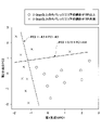
- FIG. 10 is a scatter diagram of the principal component scores obtained by substituting the above 19 types of individual data into the first principal component PC1 and the second principal component PC2.
- the “ ⁇ ” mark indicates the main component score in which the ratio of the receiving points whose throughput of 2 Gbps or more is measured is 60% or more among all the receiving points arranged in the area of 60 m ⁇ 200 m with a 1 m mesh.
- the “x” mark represents the main component score in which the ratio is less than 60%.
- a plurality of four values of depression angle a (tilt angle), height b, full width at half maximum c, and interval d satisfy "PC2 ⁇ ⁇ 4.5 ⁇ PC1-4.5". It is preferable to arrange the antenna unit. By arranging in this way, the ratio of the coverage area where the throughput of 2 Gbps or more can be obtained can be 60% or more in the area of 60 m ⁇ 200 m. That is, the antenna set 10 can form a communication area with the ground where a relatively high throughput can be obtained.
- FIG. 11 is a scatter diagram of the principal component scores obtained by substituting the above 19 types of individual data into the first principal component PC1 and the second principal component PC2.
- the “ ⁇ ” mark indicates the main component score in which the ratio of the receiving points whose throughput of 2 Gbps or more is measured is 78% or more among all the receiving points arranged in the area of 60 m ⁇ 200 m with a 1 m mesh.
- the “x” mark represents the main component score in which the ratio is less than 78%.
- the four values of depression angle a tilt angle
- height b full width at half maximum c, and interval d are “PC2 ⁇ ⁇ 4.5 ⁇ PC1-4.5 and PC2 ⁇ 0.15 ⁇ PC1 + 1”.
- the ratio of the coverage area where the throughput of 2 Gbps or more can be obtained can be 78% or more in the area of 60 m ⁇ 200 m. That is, the antenna set 10 can form a communication area with the ground where a relatively high throughput can be obtained.
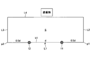
- FIG. 12 is a diagram schematically showing a rectangular area formed around two adjacent antenna units in a plan view.
- the length of the line segment k1 connecting the first antenna unit 11 and the second antenna unit 12 is d
- the line segment k1 from the first antenna unit 11 is 0.5.
- the point extended by ⁇ d is p1
- the point extended by 0.5 ⁇ d from the second antenna unit 12 is p2
- the straight line passing through p1 and p2 is L1
- the straight line passing through the point p2 and perpendicular to the straight line L1 is L3, and the farthest straight line within the range parallel to the straight line L1 and not intersecting with the obstacle (shield) that hinders the propagation of radio waves is L4, straight lines L1, L2.
- S be a square area surrounded by, L3, and L4.
- the first antenna unit 11 and the second antenna unit 12 are arranged so that the ratio of the area where the throughput can be obtained at 1 Gpbs or more is 90% or more in the square area S.
- FIG. 8 above shows a condition that the ratio of the area where the throughput can be obtained at 1 Gpbs or more is 90% or more in the square area S.
- FIG. 13 is a cross-sectional view showing an example of an antenna unit installed on the outer peripheral surface of the pole.
- the antenna unit has a plurality of radiating elements 73.
- four antennas A1, A2, A3, and A4 are exemplified as a plurality of radiating elements 73.
- the plurality of radiating elements 73 are provided on a dielectric flexible base material 72 having a conductor 75 on the back surface.
- radiating elements 73 are arranged on the outer peripheral surface of the pole at intervals of 90 °, but the number of radiating elements 73 may be less than four.
- three radiating elements 73 may be arranged at 120 ° intervals, or two may be arranged at 180 ° intervals. Further, the number of radiating elements 73 may be more than four.
- six radiating elements 73 may be arranged at 60 ° intervals, or eight may be arranged at 45 ° intervals.
- the radiating element 73 is an antenna conductor formed so as to be able to transmit and receive radio waves in a desired frequency band.
- the desired frequency band is, for example, a UHF (Ultra High Frequency) band having a frequency of 0.3 to 3 GHz, an SHF (Super High Frequency) band having a frequency of 3 to 30 GHz, and an EHF (Extremely High Frequency) band having a frequency of 30 to 300 GHz. And so on.
- the radiating element 73 functions as a radiator (radiator).
- the radiating element 73 is provided on the first main surface outside the base material 72.
- the radiating element 73 may be formed by printing a metal material so as to overlap at least a part of the ceramic layer provided on the first main surface of the base material 72. As a result, the radiating element 73 is provided on the first main surface of the base material 72 so as to straddle the portion where the ceramic layer is formed and the portion other than the ceramic layer.
- the radiating element 73 is, for example, a conductor formed in a plane.
- a conductive material such as gold, silver, copper, aluminum, chromium, lead, zinc, nickel or platinum can be used.
- the conductive material may be an alloy, for example, an alloy of copper and zinc (brass), an alloy of silver and copper, an alloy of silver and aluminum, and the like.
- the radiating element 73 may be a thin film.
- the shape of the radiating element 73 may be rectangular or circular, but is not limited to these shapes.
- Examples of another material for forming the radiating element 73 include fluorine-added tin oxide (FTO) and indium tin oxide (ITO).
- FTO fluorine-added tin oxide
- ITO indium tin oxide
- the above-mentioned ceramic layer can be formed on the first main surface of the base material 72 by printing or the like. By providing the ceramic layer, the wiring (not shown) attached to the radiating element 73 can be covered and the design is good.
- the ceramic layer may not be provided on the first main surface, or may be provided on the second main surface inside the base material 72. It is preferable that the ceramic layer is provided on the first main surface of the base material 72 because the radiation element 73 and the ceramic layer are provided on the base material 72 by printing in the same process.
- the material of the ceramic layer is glass frit or the like, and the thickness thereof is preferably 1 to 20 ⁇ m.
- the radiating element 73 is provided on the first main surface of the base material 72 in the present embodiment, it may be provided inside the base material 72. In this case, the radiating element 73 can be provided inside the base material 72 in the form of a coil, for example.
- the base material 72 is, for example, a substrate provided along the outer peripheral surface of the pole.
- the base material 72 is formed in a rectangular shape, for example, in a plan view, and has a first main surface and a second main surface.
- the first main surface of the base material 72 is provided so as to face outward.
- the second main surface of the base material 72 is provided so as to face inward.
- the material forming the base material 72 is designed according to the antenna performance such as power and directivity required for the radiating element 73, and for example, a dielectric such as glass or resin, a metal, or a composite thereof may be used. can.
- the resin is preferably a transparent resin, and polyethylene terephthalate, polyethylene, liquid crystal polymer (LCP), polyimide (PI), polyphenylene ether (PPE), polycarbonate, acrylic resin, fluororesin and the like are used. Can be mentioned. Fluororesin is preferable because of its low dielectric constant.
- fluororesin examples include an ethylene-tetrafluoroethylene-based copolymer (hereinafter, also referred to as “ETFE”), a hexafluoropropylene-tetrafluoroethylene-based copolymer (hereinafter, also referred to as “FEP”), and tetrafluoroethylene.
- ETFE ethylene-tetrafluoroethylene-based copolymer
- FEP hexafluoropropylene-tetrafluoroethylene-based copolymer
- tetrafluoroethylene tetrafluoroethylene
- ETFE is particularly preferable because it is excellent in transparency, processability and weather resistance.
- Aflex (registered trademark) may be used as the fluororesin.
- the thickness h of the base material 72 is preferably 25 ⁇ m to 10 mm.
- the thickness h of the base material 72 can be arbitrarily designed according to the place where the radiating element 73 is arranged.
- the base material 72 is a resin
- the thickness h of the film or sheet is preferably 25 to 1000 ⁇ m, more preferably 100 to 800 ⁇ m, and particularly preferably 100 to 500 ⁇ m from the viewpoint of excellent antenna holding strength.
- the surface resistivity of the conductor 75 is preferably 20 ⁇ / ⁇ (ohms per square) or less, more preferably 10 ⁇ / ⁇ or less, and further preferably 5 ⁇ / ⁇ or less.
- the conductor 75 is preferably wider than the base material 72, but may be narrower than the base material 72.
- the thickness of the conductor 75 is preferably 400 nm or less, more preferably 300 nm or less.
- the lower limit of the thickness of the conductor 75 is not particularly limited, but may be 2 nm or more, 10 nm or more, and 30 nm or more.
- the radiation element 73 is a patch element (patch antenna), but may be another element such as a dipole element (dipole antenna).
- the other antenna unit such as the second antenna unit 12 may have the same shape as the first antenna unit 11, the description of the shape of the other antenna unit is based on the above description of the shape of the first antenna unit 11. By doing so, it is omitted.
- Table 1 shows the simulation conditions when calculating the throughput on the simulation.
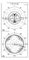
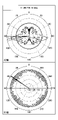
- FIGS. 14, 15 and 16 show the radiation patterns of a plurality of antenna units used during the simulation. The radiation patterns of the plurality of antenna units used during the simulation are all the same.
- FIG. 14 is a diagram showing an example of the directivity of the antenna unit in the vertical plane (XZ plane) having an azimuth angle of 0 ° and in the XY plane when a beam of 11 dBi is emitted at a tilt angle of 5 ° with respect to the XY plane.
- FIG. 15 is a diagram showing an example of the directivity of the antenna unit in a vertical plane (XZ plane) having an azimuth angle of 0 ° and in the XY plane when a beam of 11 dBi is emitted at a tilt angle of 10 ° with respect to the XY plane. be.
- 16 is a diagram showing an example of the directivity of the antenna unit in the vertical plane (XZ plane) having an azimuth angle of 0 ° and in the XY plane when a beam of 14 dBi is emitted at a tilt angle of 10 ° with respect to the XY plane.
- the gain of 11 dBi corresponds to a half-value width of 10 °
- the gain of 14 dBi corresponds to a half-value width of 5 °.
- FIG. 17 is a distribution diagram showing an example of the throughput obtained when three antenna units having the characteristics of FIG. 14 are arranged at intervals of 20 m.
- FIG. 18 is a distribution diagram showing an example of the throughput obtained when three antenna units having the characteristics of FIG. 15 are arranged at intervals of 20 m.
- FIG. 19 is a distribution diagram showing an example of the throughput obtained when three antenna units having the characteristics of FIG. 16 are arranged at intervals of 20 m.
- FIG. 20 is a distribution diagram showing an example of the throughput obtained when three antenna units having the characteristics of FIG. 14 are centrally arranged in the same place.
- the distributed arrangement type (FIGS. 17 to 19) can form a communication area in which a higher throughput can be obtained as compared with the centralized arrangement type (FIG. 20).
- the present invention is not limited to the above embodiment.
- Various modifications and improvements, such as combinations and substitutions with some or all of the other embodiments, are possible within the scope of the present invention.
- the structure in which the antenna unit is installed is not limited to poles.
- the antenna unit is installed in a structure that is fixed on the land, and may be installed in a structure such as a telephone pole, a utility pole, a street light, a traffic light, a sign, or a building.
- the antenna set may have two or four or more antenna units that transmit a stream in distributed MIMO. If there are four or more of these antenna units, it is possible to form a communication area where a higher throughput can be obtained. In addition, the capacity of the communication area can be increased.
Landscapes
- Engineering & Computer Science (AREA)
- Computer Networks & Wireless Communication (AREA)
- Signal Processing (AREA)
- Variable-Direction Aerials And Aerial Arrays (AREA)
Abstract
Description
分散MIMOでストリームを送信するアンテナユニット群を備えるアンテナセットであって、
前記アンテナユニット群は、相互に離れて配置された複数のアンテナユニットを含み、
前記複数のアンテナユニットは、高さが3m以上8m以下で設置され、放射パターンの水平面での無指向性角度が180度以上であり、メインローブの放射ピークが0度よりも大きく15度以下の俯角で傾斜する、アンテナセットを提供する。
e=10×log10(41253/(φHP×θHP))
という簡易な関係式が成立する。図7に示すグラフは、この関係式で得られるデータを表す。
PC1=-(a/10.6)-(b/10.8)+(c/5.7)+(d/19.8)-1.8
PC2=(a/12.0)+(b/2.5)+(c/6.6)+(d/99.6)-4.9
という結果が得られた。第1主成分PC1と第2主成分PC2との累積寄与率は、69.1%である(図9参照)。

10 アンテナセット
11,12,13 アンテナユニット
41,42,43,44,45,46,47,48 建物
50,52 道路
51 交差点
72 基材
75 導体
Claims (10)
- 分散MIMOでストリームを送信するアンテナユニット群を備えるアンテナセットであって、
前記アンテナユニット群は、相互に離れて配置された複数のアンテナユニットを含み、
前記複数のアンテナユニットは、高さが3m以上8m以下で設置され、放射パターンの水平面での無指向性角度が180度以上であり、メインローブの放射ピークが0度よりも大きく15度以下の俯角で傾斜する、アンテナセット。 - 前記複数のアンテナユニットは、それぞれ、前記メインローブの半値幅が6度以上15度以下である、請求項1に記載のアンテナセット。
- 前記複数のアンテナユニットは、それぞれ、放射パターンの水平面での指向性が360度無指向性である、請求項1又は2に記載のアンテナセット。
- 前記複数のアンテナユニットは、相互に隣接する二つのアンテナユニットを含み、
前記二つのアンテナユニットの間隔は、10m以上80m以下である、請求項1から3のいずれか一項に記載のアンテナセット。 - 前記複数のアンテナユニットの各々の俯角の平均値をa[度]、前記複数のアンテナユニットの各々の設置高さの平均値をb[m]、前記複数のアンテナユニットのそれぞれから放射されるメインローブの半値幅の平均値をc[度]、前記複数のアンテナユニットに含まれる隣り合うアンテナユニットの間隔の平均値をd[m]とするとき、
PC1=-(a/10.6)-(b/10.8)+(c/5.7)+(d/19.8)-1.8
PC2=(a/12.0)+(b/2.5)+(c/6.6)+(d/99.6)-4.9
PC2≧-4.5×PC1-4.5
を満たす、請求項1から4のいずれか一項に記載のアンテナセット。 - 前記アンテナユニット群に含まれる一のアンテナユニットから送信された電波の直接波を受信したレベルが最大になる地点において、「前記電波の反射波を受信したレベル[dB]÷前記電波の直接波を受信したレベル[dB]」は、0.7以上0.95以下である、請求項1から5のいずれか一項に記載のアンテナセット。
- 前記複数のアンテナユニットに含まれる隣り合うアンテナユニットの間に、電波を反射するリフレクターを備える、請求項1から6のいずれか一項に記載のアンテナセット。
- 前記アンテナユニット群は、第1アンテナユニットと、前記第1アンテナユニットに隣接する第2アンテナユニットとを含み、
水平面に垂直な方向から見て、前記第1アンテナユニットと前記第2アンテナユニットとを結ぶ線分の長さをd、前記第1アンテナユニットから前記線分を0.5×dだけ延長した点をp1、前記第2アンテナユニットから前記線分を0.5×dだけ延長した点をp2、p1とp2を通る直線をL1、点p1を通り直線L1に直角な直線をL2、点p2を通り直線L1に直角な直線をL3、直線L1に平行で且つ電波の伝搬を妨げる障害物と交わらない範囲内で最遠の直線をL4、直線L1,L2,L3,L4で囲まれる方形エリアをSとするとき、
方形エリアSのうち1Gpbs以上のスループットが得られるエリアの割合が90%以上となるように、前記第1アンテナユニット及び前記第2アンテナユニットは、配置される、請求項1から7のいずれか一項に記載のアンテナセット。 - 前記アンテナユニットは、土地に定着する構造物に設置される、請求項1から8のいずれか一項に記載のアンテナセット。
- 前記構造物は、電信柱、電柱、街灯、信号機、標識又は建物である、請求項9に記載のアンテナセット。
Priority Applications (4)
| Application Number | Priority Date | Filing Date | Title |
|---|---|---|---|
| CN202180073454.XA CN116491025A (zh) | 2020-11-09 | 2021-10-29 | 天线组 |
| EP21889134.9A EP4243199A4 (en) | 2020-11-09 | 2021-10-29 | ANTENNA SET |
| JP2022560755A JP7673754B2 (ja) | 2020-11-09 | 2021-10-29 | アンテナセット |
| US18/193,770 US12555926B2 (en) | 2020-11-09 | 2023-03-31 | Antenna set |
Applications Claiming Priority (2)
| Application Number | Priority Date | Filing Date | Title |
|---|---|---|---|
| JP2020186500 | 2020-11-09 | ||
| JP2020-186500 | 2020-11-09 |
Related Child Applications (1)
| Application Number | Title | Priority Date | Filing Date |
|---|---|---|---|
| US18/193,770 Continuation US12555926B2 (en) | 2020-11-09 | 2023-03-31 | Antenna set |
Publications (1)
| Publication Number | Publication Date |
|---|---|
| WO2022097581A1 true WO2022097581A1 (ja) | 2022-05-12 |
Family
ID=81457861
Family Applications (1)
| Application Number | Title | Priority Date | Filing Date |
|---|---|---|---|
| PCT/JP2021/040092 Ceased WO2022097581A1 (ja) | 2020-11-09 | 2021-10-29 | アンテナセット |
Country Status (5)
| Country | Link |
|---|---|
| US (1) | US12555926B2 (ja) |
| EP (1) | EP4243199A4 (ja) |
| JP (1) | JP7673754B2 (ja) |
| CN (1) | CN116491025A (ja) |
| WO (1) | WO2022097581A1 (ja) |
Families Citing this family (1)
| Publication number | Priority date | Publication date | Assignee | Title |
|---|---|---|---|---|
| US12362789B2 (en) * | 2022-12-22 | 2025-07-15 | Red Hat, Inc. | Wireless network for object and pattern detection |
Citations (4)
| Publication number | Priority date | Publication date | Assignee | Title |
|---|---|---|---|---|
| JP2017038195A (ja) | 2015-08-07 | 2017-02-16 | 日本電信電話株式会社 | 無線通信システム |
| WO2017135368A1 (ja) | 2016-02-05 | 2017-08-10 | 株式会社Nttドコモ | 無線通信装置 |
| JP2020504494A (ja) * | 2016-12-09 | 2020-02-06 | テレフオンアクチーボラゲット エルエム エリクソン(パブル) | 分散マッシブmimoのための改良されたアンテナ装置 |
| JP2020186500A (ja) | 2019-05-13 | 2020-11-19 | 株式会社おいなり3 | 指カバー具 |
Family Cites Families (10)
| Publication number | Priority date | Publication date | Assignee | Title |
|---|---|---|---|---|
| US20120020431A1 (en) * | 2009-04-16 | 2012-01-26 | Nec Corporation | Antenna device and multi-antenna system |
| EP2647124B1 (en) * | 2010-11-29 | 2019-06-05 | Smart Antenna Technologies Ltd | Balanced antenna system |
| GB2500927B (en) * | 2012-04-05 | 2014-11-19 | Broadcom Corp | Antenna using fading conditions to control radiation beam |
| US10205491B2 (en) * | 2015-09-28 | 2019-02-12 | Futurewei Technologies, Inc. | System and method for large scale multiple input multiple output communications |
| US10505609B2 (en) * | 2017-06-14 | 2019-12-10 | Commscope Technologies Llc | Small cell beam-forming antennas |
| US10530440B2 (en) * | 2017-07-18 | 2020-01-07 | Commscope Technologies Llc | Small cell antennas suitable for MIMO operation |
| KR102738383B1 (ko) * | 2017-11-15 | 2024-12-06 | 프라운호퍼 게젤샤프트 쭈르 푀르데룽 데어 안겐반텐 포르슝 에. 베. | 장치를 테스트하기 위한 장치, 측정 시스템, 측정 설정, 및 방법 |
| CN109004337B (zh) * | 2018-06-15 | 2019-10-25 | 深圳市信维通信股份有限公司 | 适用于5g通信的双极化毫米波天线系统及移动终端 |
| WO2020201049A1 (en) * | 2019-03-29 | 2020-10-08 | Fraunhofer-Gesellschaft zur Förderung der angewandten Forschung e.V. | Devices for communicating in a wireless communication network and methods for operating and testing the devices |
| WO2021054878A1 (en) * | 2019-09-20 | 2021-03-25 | Telefonaktiebolaget Lm Ericsson (Publ) | Method and network node with improved beamforming |
-
2021
- 2021-10-29 EP EP21889134.9A patent/EP4243199A4/en active Pending
- 2021-10-29 CN CN202180073454.XA patent/CN116491025A/zh active Pending
- 2021-10-29 WO PCT/JP2021/040092 patent/WO2022097581A1/ja not_active Ceased
- 2021-10-29 JP JP2022560755A patent/JP7673754B2/ja active Active
-
2023
- 2023-03-31 US US18/193,770 patent/US12555926B2/en active Active
Patent Citations (4)
| Publication number | Priority date | Publication date | Assignee | Title |
|---|---|---|---|---|
| JP2017038195A (ja) | 2015-08-07 | 2017-02-16 | 日本電信電話株式会社 | 無線通信システム |
| WO2017135368A1 (ja) | 2016-02-05 | 2017-08-10 | 株式会社Nttドコモ | 無線通信装置 |
| JP2020504494A (ja) * | 2016-12-09 | 2020-02-06 | テレフオンアクチーボラゲット エルエム エリクソン(パブル) | 分散マッシブmimoのための改良されたアンテナ装置 |
| JP2020186500A (ja) | 2019-05-13 | 2020-11-19 | 株式会社おいなり3 | 指カバー具 |
Non-Patent Citations (3)
| Title |
|---|
| KISHIYAMA, YOSHIHISA: "Latest wireless access technology for 5G systems and field demonstration experiment results", NTT DOCOMO TECHNICAL JOURNAL, vol. 25, no. 1, 1 April 2017 (2017-04-01), JP, pages 16 - 29, XP009536526 * |
| NTT DOCOMO TECHNICAL JOURNAL, vol. 25, no. 1, April 2017 (2017-04-01) |
| See also references of EP4243199A4 |
Also Published As
| Publication number | Publication date |
|---|---|
| CN116491025A (zh) | 2023-07-25 |
| EP4243199A1 (en) | 2023-09-13 |
| US20230246347A1 (en) | 2023-08-03 |
| JP7673754B2 (ja) | 2025-05-09 |
| JPWO2022097581A1 (ja) | 2022-05-12 |
| EP4243199A4 (en) | 2024-09-04 |
| US12555926B2 (en) | 2026-02-17 |
Similar Documents
| Publication | Publication Date | Title |
|---|---|---|
| US12261367B2 (en) | Antenna unit and window glass | |
| KR20220043213A (ko) | 빔 형성 시스템을 위한 메타 구조의 무선 인프라구조 | |
| US12057631B2 (en) | Antenna unit and window glass | |
| WO2021104191A1 (zh) | 天线单元及电子设备 | |
| EP3477771B1 (en) | Printed dipole antenna, array antenna, and communications device | |
| KR20160031860A (ko) | 무급전 재방사 중계기 및 그의 제작 방법 | |
| Susanti et al. | MIMO antenna with cross polarisation printed yagi elements for MIMO router | |
| US12218405B2 (en) | Antenna set | |
| US12555926B2 (en) | Antenna set | |
| CN108539429B (zh) | 一种用于金属载体的宽带全向斜极化天线 | |
| CN103887600B (zh) | 无线覆盖天线单元、天线组件及多天线组件 | |
| CN103401068A (zh) | 高增益宽带立体式缝隙八木天线 | |
| Mologni et al. | Investigation on the deployment of FSS as electromagnetic shielding for 5G devices | |
| EP2077604A1 (en) | Multi row antenna arrangement having a two dimentional omnidirectional transmitting and/or receiving profile | |
| CN203367475U (zh) | 天线单元、多天线组件及无线互连设备 | |
| CN203219498U (zh) | 一种无线覆盖系统 | |
| CN113871901A (zh) | 一种基于偶极子线阵的宽带高增益全向天线 | |
| TWI757835B (zh) | 毫米波基地台之天線結構的建置方法及毫米波基地台系統 | |
| CN107946756B (zh) | 一种电磁超表面加载的窄波束wlan ap天线 | |
| US20260101196A1 (en) | Metasurface reflectors and methods of wireless network configuration for wireless signal coverage improvement | |
| CN219553884U (zh) | 一种多输入多输出天线及电子设备 | |
| CN114079158B (zh) | 毫米波基地台的天线结构的建置方法及毫米波基地台系统 | |
| KR102725485B1 (ko) | 안테나 광빔폭 장치 | |
| WO2025115482A1 (ja) | 受信電力の測定方法、電力反射効率の計算方法、受信電力の測定プログラム、及び、電力反射効率の計算プログラム | |
| KR101639601B1 (ko) | 무지향성 방사체를 갖는 빔 성형 안테나 장치 |
Legal Events
| Date | Code | Title | Description |
|---|---|---|---|
| 121 | Ep: the epo has been informed by wipo that ep was designated in this application |
Ref document number: 21889134 Country of ref document: EP Kind code of ref document: A1 |
|
| ENP | Entry into the national phase |
Ref document number: 2022560755 Country of ref document: JP Kind code of ref document: A |
|
| WWE | Wipo information: entry into national phase |
Ref document number: 202180073454.X Country of ref document: CN |
|
| WWE | Wipo information: entry into national phase |
Ref document number: 2021889134 Country of ref document: EP |
|
| NENP | Non-entry into the national phase |
Ref country code: DE |
|
| ENP | Entry into the national phase |
Ref document number: 2021889134 Country of ref document: EP Effective date: 20230609 |