WO2022097688A1 - 車両管理システム - Google Patents
車両管理システム Download PDFInfo
- Publication number
- WO2022097688A1 WO2022097688A1 PCT/JP2021/040641 JP2021040641W WO2022097688A1 WO 2022097688 A1 WO2022097688 A1 WO 2022097688A1 JP 2021040641 W JP2021040641 W JP 2021040641W WO 2022097688 A1 WO2022097688 A1 WO 2022097688A1
- Authority
- WO
- WIPO (PCT)
- Prior art keywords
- vehicle
- loading
- unmanned vehicle
- instruction
- information
- Prior art date
- Legal status (The legal status is an assumption and is not a legal conclusion. Google has not performed a legal analysis and makes no representation as to the accuracy of the status listed.)
- Ceased
Links
Images








Classifications
-
- G—PHYSICS
- G05—CONTROLLING; REGULATING
- G05D—SYSTEMS FOR CONTROLLING OR REGULATING NON-ELECTRIC VARIABLES
- G05D1/00—Control of position, course, altitude or attitude of land, water, air or space vehicles, e.g. using automatic pilots
- G05D1/02—Control of position or course in two dimensions
- G05D1/021—Control of position or course in two dimensions specially adapted to land vehicles
- G05D1/0287—Control of position or course in two dimensions specially adapted to land vehicles involving a plurality of land vehicles, e.g. fleet or convoy travelling
- G05D1/0291—Fleet control
- G05D1/0297—Fleet control by controlling means in a control room
-
- E—FIXED CONSTRUCTIONS
- E02—HYDRAULIC ENGINEERING; FOUNDATIONS; SOIL SHIFTING
- E02F—DREDGING; SOIL-SHIFTING
- E02F9/00—Component parts of dredgers or soil-shifting machines, not restricted to one of the kinds covered by groups E02F3/00 - E02F7/00
- E02F9/20—Drives; Control devices
- E02F9/2025—Particular purposes of control systems not otherwise provided for
- E02F9/205—Remotely operated machines, e.g. unmanned vehicles
-
- B—PERFORMING OPERATIONS; TRANSPORTING
- B60—VEHICLES IN GENERAL
- B60K—ARRANGEMENT OR MOUNTING OF PROPULSION UNITS OR OF TRANSMISSIONS IN VEHICLES; ARRANGEMENT OR MOUNTING OF PLURAL DIVERSE PRIME-MOVERS IN VEHICLES; AUXILIARY DRIVES FOR VEHICLES; INSTRUMENTATION OR DASHBOARDS FOR VEHICLES; ARRANGEMENTS IN CONNECTION WITH COOLING, AIR INTAKE, GAS EXHAUST OR FUEL SUPPLY OF PROPULSION UNITS IN VEHICLES
- B60K35/00—Instruments specially adapted for vehicles; Arrangement of instruments in or on vehicles
-
- B—PERFORMING OPERATIONS; TRANSPORTING
- B60—VEHICLES IN GENERAL
- B60K—ARRANGEMENT OR MOUNTING OF PROPULSION UNITS OR OF TRANSMISSIONS IN VEHICLES; ARRANGEMENT OR MOUNTING OF PLURAL DIVERSE PRIME-MOVERS IN VEHICLES; AUXILIARY DRIVES FOR VEHICLES; INSTRUMENTATION OR DASHBOARDS FOR VEHICLES; ARRANGEMENTS IN CONNECTION WITH COOLING, AIR INTAKE, GAS EXHAUST OR FUEL SUPPLY OF PROPULSION UNITS IN VEHICLES
- B60K35/00—Instruments specially adapted for vehicles; Arrangement of instruments in or on vehicles
- B60K35/10—Input arrangements, i.e. from user to vehicle, associated with vehicle functions or specially adapted therefor
-
- B—PERFORMING OPERATIONS; TRANSPORTING
- B60—VEHICLES IN GENERAL
- B60K—ARRANGEMENT OR MOUNTING OF PROPULSION UNITS OR OF TRANSMISSIONS IN VEHICLES; ARRANGEMENT OR MOUNTING OF PLURAL DIVERSE PRIME-MOVERS IN VEHICLES; AUXILIARY DRIVES FOR VEHICLES; INSTRUMENTATION OR DASHBOARDS FOR VEHICLES; ARRANGEMENTS IN CONNECTION WITH COOLING, AIR INTAKE, GAS EXHAUST OR FUEL SUPPLY OF PROPULSION UNITS IN VEHICLES
- B60K35/00—Instruments specially adapted for vehicles; Arrangement of instruments in or on vehicles
- B60K35/20—Output arrangements, i.e. from vehicle to user, associated with vehicle functions or specially adapted therefor
-
- B—PERFORMING OPERATIONS; TRANSPORTING
- B60—VEHICLES IN GENERAL
- B60K—ARRANGEMENT OR MOUNTING OF PROPULSION UNITS OR OF TRANSMISSIONS IN VEHICLES; ARRANGEMENT OR MOUNTING OF PLURAL DIVERSE PRIME-MOVERS IN VEHICLES; AUXILIARY DRIVES FOR VEHICLES; INSTRUMENTATION OR DASHBOARDS FOR VEHICLES; ARRANGEMENTS IN CONNECTION WITH COOLING, AIR INTAKE, GAS EXHAUST OR FUEL SUPPLY OF PROPULSION UNITS IN VEHICLES
- B60K35/00—Instruments specially adapted for vehicles; Arrangement of instruments in or on vehicles
- B60K35/60—Instruments characterised by their location or relative disposition in or on vehicles
-
- B—PERFORMING OPERATIONS; TRANSPORTING
- B60—VEHICLES IN GENERAL
- B60K—ARRANGEMENT OR MOUNTING OF PROPULSION UNITS OR OF TRANSMISSIONS IN VEHICLES; ARRANGEMENT OR MOUNTING OF PLURAL DIVERSE PRIME-MOVERS IN VEHICLES; AUXILIARY DRIVES FOR VEHICLES; INSTRUMENTATION OR DASHBOARDS FOR VEHICLES; ARRANGEMENTS IN CONNECTION WITH COOLING, AIR INTAKE, GAS EXHAUST OR FUEL SUPPLY OF PROPULSION UNITS IN VEHICLES
- B60K35/00—Instruments specially adapted for vehicles; Arrangement of instruments in or on vehicles
- B60K35/80—Arrangements for controlling instruments
-
- E—FIXED CONSTRUCTIONS
- E02—HYDRAULIC ENGINEERING; FOUNDATIONS; SOIL SHIFTING
- E02F—DREDGING; SOIL-SHIFTING
- E02F9/00—Component parts of dredgers or soil-shifting machines, not restricted to one of the kinds covered by groups E02F3/00 - E02F7/00
- E02F9/20—Drives; Control devices
- E02F9/2025—Particular purposes of control systems not otherwise provided for
- E02F9/2045—Guiding machines along a predetermined path
-
- E—FIXED CONSTRUCTIONS
- E02—HYDRAULIC ENGINEERING; FOUNDATIONS; SOIL SHIFTING
- E02F—DREDGING; SOIL-SHIFTING
- E02F9/00—Component parts of dredgers or soil-shifting machines, not restricted to one of the kinds covered by groups E02F3/00 - E02F7/00
- E02F9/26—Indicating devices
- E02F9/264—Sensors and their calibration for indicating the position of the work tool
-
- G—PHYSICS
- G01—MEASURING; TESTING
- G01C—MEASURING DISTANCES, LEVELS OR BEARINGS; SURVEYING; NAVIGATION; GYROSCOPIC INSTRUMENTS; PHOTOGRAMMETRY OR VIDEOGRAMMETRY
- G01C21/00—Navigation; Navigational instruments not provided for in groups G01C1/00 - G01C19/00
- G01C21/20—Instruments for performing navigational calculations
-
- G—PHYSICS
- G05—CONTROLLING; REGULATING
- G05D—SYSTEMS FOR CONTROLLING OR REGULATING NON-ELECTRIC VARIABLES
- G05D1/00—Control of position, course, altitude or attitude of land, water, air or space vehicles, e.g. using automatic pilots
- G05D1/60—Intended control result
- G05D1/656—Interaction with payloads or external entities
- G05D1/667—Delivering or retrieving payloads
-
- G—PHYSICS
- G05—CONTROLLING; REGULATING
- G05D—SYSTEMS FOR CONTROLLING OR REGULATING NON-ELECTRIC VARIABLES
- G05D1/00—Control of position, course, altitude or attitude of land, water, air or space vehicles, e.g. using automatic pilots
- G05D1/60—Intended control result
- G05D1/69—Coordinated control of the position or course of two or more vehicles
- G05D1/698—Control allocation
- G05D1/6987—Control allocation by centralised control off-board any of the vehicles
-
- G—PHYSICS
- G06—COMPUTING OR CALCULATING; COUNTING
- G06Q—INFORMATION AND COMMUNICATION TECHNOLOGY [ICT] SPECIALLY ADAPTED FOR ADMINISTRATIVE, COMMERCIAL, FINANCIAL, MANAGERIAL OR SUPERVISORY PURPOSES; SYSTEMS OR METHODS SPECIALLY ADAPTED FOR ADMINISTRATIVE, COMMERCIAL, FINANCIAL, MANAGERIAL OR SUPERVISORY PURPOSES, NOT OTHERWISE PROVIDED FOR
- G06Q10/00—Administration; Management
- G06Q10/08—Logistics, e.g. warehousing, loading or distribution; Inventory or stock management
-
- G—PHYSICS
- G16—INFORMATION AND COMMUNICATION TECHNOLOGY [ICT] SPECIALLY ADAPTED FOR SPECIFIC APPLICATION FIELDS
- G16Y—INFORMATION AND COMMUNICATION TECHNOLOGY SPECIALLY ADAPTED FOR THE INTERNET OF THINGS [IoT]
- G16Y10/00—Economic sectors
- G16Y10/40—Transportation
-
- G—PHYSICS
- G16—INFORMATION AND COMMUNICATION TECHNOLOGY [ICT] SPECIALLY ADAPTED FOR SPECIFIC APPLICATION FIELDS
- G16Y—INFORMATION AND COMMUNICATION TECHNOLOGY SPECIALLY ADAPTED FOR THE INTERNET OF THINGS [IoT]
- G16Y40/00—IoT characterised by the purpose of the information processing
- G16Y40/10—Detection; Monitoring
-
- G—PHYSICS
- G16—INFORMATION AND COMMUNICATION TECHNOLOGY [ICT] SPECIALLY ADAPTED FOR SPECIFIC APPLICATION FIELDS
- G16Y—INFORMATION AND COMMUNICATION TECHNOLOGY SPECIALLY ADAPTED FOR THE INTERNET OF THINGS [IoT]
- G16Y40/00—IoT characterised by the purpose of the information processing
- G16Y40/30—Control
-
- E—FIXED CONSTRUCTIONS
- E02—HYDRAULIC ENGINEERING; FOUNDATIONS; SOIL SHIFTING
- E02F—DREDGING; SOIL-SHIFTING
- E02F9/00—Component parts of dredgers or soil-shifting machines, not restricted to one of the kinds covered by groups E02F3/00 - E02F7/00
- E02F9/26—Indicating devices
- E02F9/264—Sensors and their calibration for indicating the position of the work tool
- E02F9/265—Sensors and their calibration for indicating the position of the work tool with follow-up actions (e.g. control signals sent to actuate the work tool)
Definitions
- the present invention relates to a vehicle management system, and more particularly to a vehicle management system in a field where a loading machine performs loading work on an unmanned vehicle.
- a vehicle management system equipped with a dump truck that is, an automated guided vehicle that autonomously travels without an operator boarding and a control station that communicates with an automated guided vehicle via a wireless communication line is used.
- the loading work of loading earth and sand, ore, etc. (hereinafter referred to as "earth and sand, etc.") into an automatic vehicle is performed by a loading machine such as a shovel operated by an operator. Since the operator does not board the automatic guided vehicle, the operator of the loading machine must instruct the unmanned vehicle to call in to the loading position and start after loading, in addition to operating the loading machine itself. More complicated procedures are required. Therefore, in order to realize high productivity in the vehicle management system, it is necessary to have a mechanism that allows the operator of the loading machine to efficiently carry out the work.
- the operator of the loading machine can efficiently guide the unmanned vehicle by instructing the loading position, but it is possible to efficiently give the start instruction to the unmanned vehicle. Can not. Further, since the switch of the operation lever of the loading machine is assigned a function of sounding an alarm, a function of turning on / off a wireless call, and the like, there is little room to increase the function of instructing an unmanned vehicle. Further, even if the number of switches for the instruction function for the automatic guided vehicle is increased, it may induce an erroneous operation for an inexperienced operator, which in turn causes a decrease in work efficiency. Therefore, there is a problem that it is difficult for the operator of the loading machine to improve the efficiency of the loading work for the automatic guided vehicle.
- the present invention has been made to solve such a technical problem, and an object of the present invention is to provide a vehicle management system capable of improving the efficiency of loading work for an automatic guided vehicle by an operator of a loading machine.
- the vehicle management system includes an unmanned vehicle capable of autonomous traveling, a loading machine to which a bucket is attached by an articulated structure and loading work on the unmanned vehicle, and vehicle allocation management and traffic of the unmanned vehicle.
- a vehicle management system configured so that a control station that performs control and a control station can communicate with each other, and information on the position, orientation, and loading platform dimensions of the unmanned vehicle is acquired and stored, and these information are transmitted to the control station.
- a toe position calculation unit that calculates the toe position
- a machine information management unit that acquires and stores the toe position calculated by the toe position calculation unit, and transmits information on the toe position to the control station, and the above.
- the loading area of the unmanned vehicle was calculated based on the information on the position, orientation, and platform size of the unmanned vehicle transmitted from the vehicle information management unit, and the calculated loading area and the machine information management unit transmitted the calculated loading area. It is characterized by including an unmanned vehicle instruction unit that gives a call instruction or a start instruction to the unmanned vehicle based on the tip position.
- the automatic guided vehicle indicator is calculated from the toe position calculated from the information on the position, orientation and angle of each joint of the loading machine, and the position, orientation and loading platform dimensions of the unmanned vehicle. Based on the loading area of the unmanned vehicle, a call instruction or a start instruction is given to the unmanned vehicle. As a result, the workload of the operator of the loading machine can be reduced, so that the operator of the loading machine can improve the efficiency of the loading work on the automatic guided vehicle.
- the operator of the loading machine can improve the efficiency of loading work for an automatic guided vehicle.
- FIG. 1 is a schematic configuration diagram showing a vehicle management system according to the first embodiment.
- the vehicle management system 1 of the present embodiment is a system used at a work site such as an open pit mine, and has one or more loading machines 10 for excavation work and loading work, and loading. It includes one or more unmanned vehicles 20 (unmanned vehicle 20A, unmanned vehicle 20B) for transporting earth and sand loaded from the machine 10, and a control station 30 for managing the allocation of the unmanned vehicle 20 and controlling traffic.
- the loading machine 10, the automatic guided vehicle 20, and the control station 30 are configured to be able to communicate with each other by the wireless communication line 40.
- a plurality of radio base stations 41 are installed in an open pit mine or the like, and the loading machine 10, the automatic guided vehicle 20, and the control station 30 transmit and receive each other via these radio base stations 41. ing.
- the partial section of the transport route 60 divided by the nodes on the map data indicating the transport route 60 is exclusively permitted to travel based on the position of each automatic guided vehicle 20.
- the so-called travel permission section control method is used.
- the travel permit section control method for example, when a travel permit is requested for a front section adjacent to the travel permit section of the own vehicle, the requested front section is set as a travel permit for another vehicle or as no entry. If so, the vehicle is not allowed to travel in the section ahead. Therefore, the vehicle stops at the end of the currently permitted section and waits until the preceding section is permitted to travel.
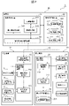
- FIG. 2 is a functional block diagram showing a vehicle management system according to the first embodiment.
- one loading machine 10 and one unmanned vehicle 20 are shown, but the same configuration is used when two or more of them are present.
- the loading machine 10 is a machine to which a bucket is attached by an articulated structure.
- the loading machine 10 of the present embodiment is, for example, a backhoe such as a hydraulic excavator provided with a work device rotatably provided in the vertical direction with respect to the machine body, and the work device has a boom, an arm, a bucket, and the like. ..
- the loading machine 10 is not limited to the hydraulic excavator, and may be, for example, a wheel loader or the like.
- the loading machine 10 includes a loading machine information management device 11, a loading machine position sensor 12, a loading machine orientation sensor 13, a working device angle sensor 14, an instruction input device 15, and a loading machine wireless communication device 16. There is.
- the loading machine position sensor 12 is, for example, a GPS (Global Positioning System), measures the position of the loading machine 10, and outputs the measured position to the loading machine information management device 11. note that.
- a device for measuring the position of the loading machine 10 instead of the loading machine position sensor 12, for example, a device that receives positioning radio waves from a plurality of navigation satellites 70 (see FIG. 1) and measures the position of the loading machine 10. May be used.
- the loading machine orientation sensor 13 measures the orientation of the loading machine 10 and outputs the measured orientation to the loading machine information management device 11.
- the loading machine directional sensor 13 may be, for example, a dual antenna GPS having two antennas and measuring the directional from the relative position of the antenna position acquired by each, or may be a directional sensor using magnetism.
- the working device angle sensor 14 measures the relative angle of each joint of the working device such as a boom, an arm, and a bucket. Specifically, the work device angle sensor 14 measures the relative angle between the machine body and the boom, the relative angle between the boom and the arm, and the relative angle between the arm and the bucket, and the measured angles are loaded into the machine information management. Output to device 11.
- the working device angle sensor 14 is, for example, a potentiometer attached to each joint.
- the instruction input device 15 is for the operator of the loading machine 10 to input an instruction to the unmanned vehicle 20, and is connected to the loading machine information management device 11.
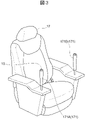
- the instruction input device 15 is, for example, a switch arranged in the cockpit 17 so that the operator can easily operate the instruction input device 15.
- the cockpit 17 arranged in the driver's cab of the loading machine 10 has a pair of operation levers 171 (operation levers 171) that can be grasped by the left and right hands when the operator sits down. 171A and 171B) are attached.
- the operator can operate the boom, arm, bucket, etc. of the loading machine 10 via the operation lever 171.
- An instruction input device 15 is arranged above the operation lever 171 as a switch that can be operated quickly at all times by, for example, the right thumb while holding the operation lever 171.
- the instruction input device 15 is not necessarily a switch arranged above the operation lever 171 but is other than a switch as long as the operator can easily input an instruction to the unmanned vehicle 20 while performing a normal operation such as loading. It may be one. Further, the arrangement position is not limited to the upper part of the operation lever 171.
- the loading machine wireless communication device 16 is, for example, a wireless device for connecting to a wireless communication line 40.
- the loading machine wireless communication device 16 transmits / receives information to / from the automatic guided vehicle 20 or the control station 30 via the wireless communication line 40.
- the loading machine information management device 11 is, for example, a CPU (Central Processing Unit) that executes an operation, a ROM (Read Only Memory) as a secondary storage device that records a program for an operation, and storage or temporary operation progress. It is composed of a microcomputer in combination with a RAM (Random Access Memory) as a temporary storage device for storing control variables, and controls the operation of the loading machine 10 by executing a stored program.
- a CPU Central Processing Unit
- ROM Read Only Memory
- RAM Random Access Memory
- the loading machine information management device 11 has a toe position calculation unit 111 and a machine information management unit 112.
- the toe position calculation unit 111 includes position information output from the loading machine position sensor 12, orientation information output from the loading machine orientation sensor 13, and the angle of each joint output from the working device angle sensor 14.
- the position of the toe of the bucket is calculated geometrically based on the information in. Further, the toe position calculation unit 111 outputs the calculated toe position to the machine information management unit 112.
- the machine information management unit 112 acquires and stores the toe position information calculated by the toe position calculation unit 111, and transmits the toe position information to the control station 30 via the loading machine wireless communication device 16. .. Further, when the instruction input device 15 receives an instruction input, the machine information management unit 112 provides operation instruction information to the automatic guided vehicle 20 (hereinafter referred to as "unmanned vehicle operation instruction information") in response to the instruction input. Further generated, and the generated unmanned vehicle operation instruction information is transmitted to the control station 30 together with the information on the tip position.
- unmanned vehicle operation instruction information an automatic guided vehicle 20
- the machine information management unit 112 may further acquire and store information on the angle of each joint in addition to the toe position. In this case, the machine information management unit 112 transmits information on the toe position and the angle of each joint to the control station 30 via the loading machine wireless communication device 16.
- the automatic guided vehicle 20 is, for example, a dump truck capable of autonomously traveling based on an instruction from the control station 30.
- the automatic guided vehicle 20 includes an automatic guided vehicle control device 21, a traveling drive device 22, an automated guided vehicle position sensor 23, an automated guided vehicle orientation sensor 24, a loading sensor 25, an automated guided vehicle storage device 26, and an automated guided vehicle wireless communication device 27. ..
- the traveling drive device 22 drives the traveling of the unmanned vehicle 20 based on the control signal of the unmanned vehicle control device 21.
- the traveling drive device 22 includes, for example, a steering motor for changing the steering angle of the unmanned vehicle 20, a traveling motor for driving the unmanned vehicle 20, a brake, and the like.
- the unmanned vehicle position sensor 23 is, for example, a GPS device or the like, measures the position of the own vehicle, and outputs the measured position to the unmanned vehicle control device 21.
- the unmanned vehicle position sensor 23 may be a combination of GPS and an inertial measurement unit (IMU), or may specify a position using radio waves from a base station installed on the ground. good.
- IMU inertial measurement unit
- the unmanned vehicle orientation sensor 24 is, for example, a sensor using a GPS device or magnetism, measures the orientation of the unmanned vehicle 20, and outputs the measured orientation to the unmanned vehicle control device 21.
- the load sensor 25 measures the weight (that is, the load capacity) of the load loaded on the unmanned vehicle 20, and may be a weight sensor provided on the seated portion of the loading platform, and may be a vehicle body and front / rear / left / right wheels. The weight may be estimated based on the pressure of the suspension cylinder interposed between the and. The load sensor 25 outputs the measured load amount to the automatic guided vehicle control device 21.
- the unmanned vehicle storage device 26 is a non-volatile storage medium capable of reading and writing information, and stores an OS (Operating System), various control programs, application programs, databases, and the like. Further, the automatic guided vehicle storage device 26 has a map information storage unit 261.
- the unmanned vehicle wireless communication device 27 is, for example, a wireless device for connecting to a wireless communication line 40.
- the automatic guided vehicle wireless communication device 27 transmits / receives information to / from the loading machine 10 or the control station 30 via the wireless communication line 40.
- the unmanned vehicle control device 21 includes, for example, a CPU (Central Processing Unit) that executes an operation, a ROM (Read Only Memory) as a secondary storage device that records a program for the operation, and storage or temporary operation progress. It is composed of a microcomputer in combination with a RAM (Random Access Memory) as a temporary storage device for storing control variables, and controls the operation of the unmanned vehicle 20 by executing a stored program.
- a CPU Central Processing Unit
- ROM Read Only Memory
- RAM Random Access Memory
- the unmanned vehicle control device 21 has a vehicle information management unit 211 and an autonomous travel control unit 212.
- the vehicle information management unit 211 acquires the position information output from the unmanned vehicle position sensor 23, the orientation information output from the unmanned vehicle orientation sensor 24, and the load capacity information output from the loading sensor 25. , And the information is transmitted to the control station 30 via the automatic guided vehicle radio communication device 27. Further, the vehicle information management unit 211 outputs the information on the position, direction, and load capacity to the autonomous travel control unit 212. Further, when the vehicle information management unit 211 receives information on the travel route and the travel permission section for the own vehicle from the control control unit 312 (described later) of the control station 30, the received information is output to the autonomous travel control unit 212. do.
- the autonomous travel control unit 212 deviates from the travel permission section while following the travel permission route based on the position, direction, load capacity, travel route, and travel permission section information output from the vehicle information management unit 211. Acceleration / deceleration control signals and steering control signals for driving the unmanned vehicle 20 so as not to be generated are generated. Further, the autonomous travel control unit 212 outputs these generated control signals to the travel drive device 22.
- the control station 30 includes a control control device 31, a control station storage device 32, and a control station radio communication device 33.
- the control station storage device 32 is a non-volatile storage medium capable of reading and writing information, and stores an OS (Operating System), various control programs, application programs, databases, and the like.
- the control station storage device 32 has a vehicle allocation management information storage unit 321, a control information storage unit 322, and a map information storage unit 323.
- the control station wireless communication device 33 is, for example, a wireless device for connecting to a wireless communication line 40, and has an antenna 331 (see FIG. 1).
- the control station wireless communication device 33 transmits / receives information to / from the loading machine 10 or the unmanned vehicle 20 via the wireless communication line 40.
- the control control device 31 includes, for example, a CPU (Central Processing Unit) that executes an operation, a ROM (Read Only Memory) as a secondary storage device that records a program for the operation, and storage and temporary control of the operation progress. It is composed of a microcomputer in combination with a RAM (Random Access Memory) as a temporary storage device for storing variables, and controls the operation of the control station 30 by executing the stored program.
- a CPU Central Processing Unit
- ROM Read Only Memory
- RAM Random Access Memory
- the control control device 31 has a vehicle allocation management unit 311, a control control unit 312, and an automatic guided vehicle instruction unit 313.
- the vehicle allocation management unit 311 sets a travel route to the destination of the automatic guided vehicle 20. For example, when the automatic guided vehicle 20 is in the loading yard, the vehicle allocation management unit 311 sets a traveling route to the lumber yard. On the other hand, when the automatic guided vehicle 20 is in the lumber yard, the vehicle allocation management unit 311 sets a travel route to the loading yard.
- the travel route set by the vehicle allocation management unit 311 is stored in the vehicle allocation management information storage unit 321 as vehicle allocation management information, for example, in the form of a table.
- FIG. 4A is a diagram showing an example of a table of vehicle allocation management information.
- the travel route set by the vehicle allocation management unit 311 is recorded for each vehicle ID that uniquely identifies the unmanned vehicle.
- the traveling route is composed of an area exit side route, a transport route, and an area entrance side route.
- the transport route indicates a route from the loading yard exit point nod_Lout to the lumber yard entrance point node_Din, or from the lumber yard exit point nod_Dout to the loading yard entrance point node_Lin, that is, a route on the transport path.
- the area entrance side route indicates a route from the loading area entrance point node_Lin to the loading position node_LP, or a route from the lumber yard entrance point node_Din to the release position node_DP, that is, a route from the work area entrance to the work point.
- the area exit side route indicates a route from the loading position nod_LP to the loading site exit point node_Lout, or a route from the discharge position node_DP to the lumber yard exit point node_Dout, that is, a route from the work point to the work area exit point.
- Each route is defined as a coordinate point sequence (node sequence) for the automatic guided vehicle 20 to follow as a target track.
- the area entrance side route and the area exit side route are collectively referred to as an "intra-area route”.
- the transport route map information that can be set as the transport route is stored in the map information storage unit 323 in advance in a format that matches the shape of the transport route.
- the map information in the area that can be set as the route in the area is generated by the control control unit 312 when the loading position or the discharge position, which is the work point, is specified, and is generated in the map information storage unit 323. It is remembered. Only one map information in the area may be generated for the same work area, or a plurality of map information may be generated. When a plurality of vehicles are generated, the vehicle allocation management unit 311 may select one of the plurality of map information in the area and set the route in the area when setting the travel route for the automatic guided vehicle 20.
- the vehicle allocation management unit 311 when setting the travel route for the automatic guided vehicle 20, the vehicle allocation management unit 311 simultaneously sets the transport route and the intra-area route when the generated intra-area route exists for the work area of the destination. do. On the other hand, when the generated intra-area route does not exist for the work area of the destination, the vehicle allocation management unit 311 first sets a transport route to the entrance point of the work area to be the destination, and then sets the transport route to the work point in the area. Is specified, and the route within the area may be set when the map information within the area is generated.
- control information Based on the traffic control information stored in the control information storage unit 322 (hereinafter, simply referred to as "control information"), the control control unit 312 sets a part of the travel route of the unmanned vehicle 20 only for the unmanned vehicle 20. It is set as a travel permission section to which a travel permission is granted.
- FIG. 4B is a diagram showing an example of a table of control information stored in the control information storage unit.
- the node ID and the "travel permit vehicle” indicating an unmanned vehicle that has been granted a travel permit for the section indicated by each node ID (the section to the next node on the route) are associated with each other.
- the control control unit 312 sets the front section where the travel permission is possible as the travel permission section for the unmanned vehicle 20 according to the position of the unmanned vehicle 20.
- the automatic guided vehicle 20 travels according to the node of the set section.
- the travel permit section control method is adopted. Therefore, when the front section of the travel permission section set for the unmanned vehicle 20A is set as the travel permission section for another unmanned vehicle 20B, the control control unit 312 travels in the front section with respect to the unmanned vehicle 20A. not allowed. In this case, the automatic guided vehicle 20A stops so as not to exceed the terminal node of the currently permitted travel permission section, and waits until the front section is permitted to travel.
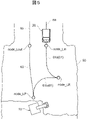
- control control unit 312 generates the map information in the area based on the work point designated in the work area, and stores the generated map information in the area in the map information storage unit 323. For example, as shown in FIG. 5, when the loading position node_LP is specified in the loading field 50, the control control unit 312 generates an intra-area route in the loading field 50.
- sections 60 and 63 indicate a transport route
- sections 61a and 61b indicate an area entrance side route
- section 62 indicates an area exit side route.
- the transport route is set based on the transport route map information set to connect to the loading area 50.
- the loading position nod_LP is designated by the automatic guided vehicle instruction unit 313 based on the toe position of the loading machine 10.
- the control control unit 312 determines the map information in the area for the automatic guided vehicle 20 to travel based on the loading area entrance point node_Lin, the loading area exit point node_Lout, and the loading position node_LP. To generate.
- the route on the area entrance side may include a turning point node_LR for switching forward or backward of the unmanned vehicle 20.
- a straight line or an arc which is a partial element of the route within the range where the generation of the route is permitted in the work area. It is performed by searching for an appropriate route based on an index such as the shortest path length from the candidates based on the combination of.
- control control unit 312 also generates map information within the area based on the designated lumber yard.
- the soil discharge position may be specified by an operator such as a bulldozer working at the lumber yard or an operator who remotely controls the control station.
- the vehicle allocation management unit 311 is notified that the area map information is newly generated. For example, when the in-area route is generated based on the loading position instructed as described above, the control control unit 312 notifies the vehicle allocation management unit 311 that the in-area route is newly generated. Then, when there is an automatic guided vehicle 20 in which the transport route to the loading site is set as the travel route and the area entrance side route is not set, the vehicle allocation management unit 311 uses the generated map information in the area as the travel route. Based on this, the area entrance side route of the automatic guided vehicle 20 is set.
- the unmanned vehicle instruction unit 313 calculates the loading area of the unmanned vehicle 20 based on the information on the position, orientation and loading platform size of the unmanned vehicle 20 transmitted from the vehicle information management unit 211 of the unmanned vehicle 20. Further, the unmanned vehicle instruction unit 313 gives a call instruction and a start instruction to the unmanned vehicle 20 based on the calculated loading area and the toe position transmitted from the machine information management unit 112 of the loading machine 10.
- the loading position is specified for the control control unit 312, map information in the area is generated based on the loading position, and the generated map information is set as a traveling route to the loading position of the automatic guided vehicle 20.
- the series of processes is referred to as "calling instruction" for the automatic guided vehicle 20.
- the process of setting a new travel route from the area exit side route while the automatic vehicle 20 is waiting at the loading position until the loading work is completed is called a "start instruction" for the automatic vehicle 20.
- the unmanned vehicle instruction unit 313 first calculates and calculates the loading area of the unmanned vehicle 20.
- a call instruction or a start instruction for the automatic guided vehicle 20 was selected (in other words, determined) based on the loaded area and the toe position calculated by the toe position calculation unit 111, and selected via the control control unit 312. Give instructions.
- the unmanned vehicle instruction unit 313 specifies the loading position to the control control unit 312 and requests the call-in instruction to the unmanned vehicle 20.
- the control control unit 312 generates map information in the area based on the designated loading position, and further instructs the automatic guided vehicle 20 to travel on the area entrance side route to the loading position in cooperation with the vehicle allocation management unit 311. ..
- the unmanned vehicle instruction unit 313 requests the control control unit 312 to instruct the unmanned vehicle 20 to start.
- the control control unit 312 in cooperation with the vehicle allocation management unit 311, instructs the automatic guided vehicle 20 to travel on the area exit side route to the loading area exit point and the transport route.
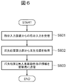
- FIG. 6 is a flowchart showing the processing contents of the loading machine information management device
- FIG. 7 is a diagram for explaining the calculation of the toe position of the bucket in the loading machine.
- the machine information management unit 112 receives the instruction input from the instruction input device 15 (step S601). Subsequently, the machine information management unit 112 acquires the toe position at that time from the toe position calculation unit 111 (step S602).
- the toe position 103 of the bucket is calculated by the toe position calculation unit 111 based on the information of the position 101 of the loading machine 10, the orientation 102, and the angles ⁇ 1, ⁇ 2, and ⁇ 3 of each joint.
- the position 101 of the loading machine 10 is measured by the loading machine position sensor 12, and the orientation 102 of the loading machine 10 is measured by the loading machine orientation sensor 13.
- the working device 18 of the loading machine 10 has a boom 18a, an arm 18b, and a bucket 18c.
- the angle ⁇ 1 is the relative angle between the machine body and the boom 18a
- the angle ⁇ 2 is the relative angle between the boom 18a and the arm 18b
- the angle ⁇ 3 is the relative angle between the arm 18b and the bucket 18c.
- Each of these angles is measured by the working device angle sensor 14.
- ⁇ 1, ⁇ 2, and ⁇ 3 are collectively referred to as “working device angle”.
- the toe position calculation unit 111 uses the information of the position 101, the orientation 102 of the loading machine 10, the working device angles ⁇ 1, ⁇ 2, and ⁇ 3, and the dimensions of the working device to excavate the toe position 103 by the bucket 18c. It is calculated geometrically as the center position of the cutting edge at the time of cutting. Subsequently, the toe position calculation unit 111 outputs the calculated toe position to the machine information management unit 112. As a result, the machine information management unit 112 can acquire the toe position.
- the machine information management unit 112 transmits the acquired toe position and the automatic guided vehicle operation instruction information to the control station 30 via the loading machine wireless communication device 16 (step S603).
- FIG. 8 is a flowchart showing the processing contents of the control control device
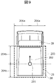
- FIG. 9 is a diagram for explaining a loading area of an automatic guided vehicle
- FIG. 10 is a diagram for explaining a situation in which a call instruction is given to an automatic guided vehicle
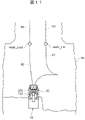
- FIG. 11 is a diagram for explaining a situation in which a start instruction is given to an automatic guided vehicle.
- the automatic guided vehicle instruction unit 313 receives the information transmitted from the machine information management unit 112 via the control station wireless communication device 33 (step S801). Subsequently, the unmanned vehicle instruction unit 313 extracts the unmanned vehicle 20 existing around the loading machine 10 based on the position of the loading machine 10 and the position of the unmanned vehicle 20 (step S802). As an extraction method, the unmanned vehicle 20 existing within a predetermined range may be extracted from the position of the loading machine 10, or a traveling route set to the loading site where the loading machine 10 is present is set. The unmanned vehicle 20 may be extracted. The number of unmanned vehicles to be extracted may be a plurality or a single number.
- the unmanned vehicle instruction unit 313 calculates the loading area of the extracted unmanned vehicle 20 (step S803).
- the calculation of the loading area of the automatic guided vehicle 20 will be described in detail with reference to FIG.
- the automatic guided vehicle instruction unit 313 repeatedly receives the reference position 201, the direction 202, and the loading platform dimensions of the automatic guided vehicle 20 transmitted from the vehicle information management unit 211 of the automatic guided vehicle 20 in a predetermined cycle (for example, 0.5 seconds).
- the reference position 201 of the unmanned vehicle 20 is, for example, the position of the center of the rear wheel axle of the unmanned vehicle 20, and is measured by the unmanned vehicle position sensor 23.
- the direction 202 of the unmanned vehicle 20 is, for example, a direction indicating the front front of the unmanned vehicle 20, and is measured by the unmanned vehicle direction sensor 24.
- the loading area 203 is an area where the space surrounding the entire loading platform 28 of the automatic guided vehicle 20 is projected onto the ground surface. However, the loading area 203 does not include the canopy 29 connected to the tip of the loading platform 28.
- the loading area 203 further includes a loading platform width parameter 204a, a loading platform front length parameter 204b, and a loading platform rear length parameter 204c stored in the vehicle information management unit 211 as the loading platform dimensions of the unmanned vehicle 20. In addition, it is calculated by the automatic guided vehicle instruction unit 313.
- the loading platform front length parameter 204b and the loading platform rear length parameter 204c are parameters with reference to the reference position 201.
- the loading platform width parameter 204a is the length from the reference position 201 to the most protruding portion in the width direction of the loading platform.
- the loading platform front length parameter 204b is the length from the reference position 201 to the loading platform tip
- the loading platform rear length parameter 204c is the length from the reference position 201 to the loading platform rear end. And these parameters are peculiar to each vehicle ID.
- the automatic guided vehicle instruction unit 313 stacks the toe positions based on the calculated loading area 203 of the plurality of unmanned vehicles 20 and the toe position 103 of the loading machine 10 transmitted from the machine information management unit 112. It is determined whether or not it exists in the embedded region (step S804).
- the automatic guided vehicle instruction unit 313 calls the automatic guided vehicle 20 via the control control unit 312 with the toe position as the loading position. Give an instruction (step S805). That is, as described above, the automatic guided vehicle instruction unit 313 designates the toe position of the loading machine 10 as the loading position.
- the control control unit 312 generates map information in the area based on the designated toe position, and further sets a travel route to the loading position for the automatic guided vehicle 20 in cooperation with the vehicle allocation management unit 311.
- FIG. 10 shows a state in which the area entrance side route in the loading area is not set and the automatic guided vehicle 20 is waiting at the end of the transport route 60.
- the control control unit 312 generates map information of the section 61 on the area entrance side and the section 62 on the area exit side as map information in the area based on the loading position designated by the automatic guided vehicle instruction unit 313. Further, the control control unit 312 cooperates with the vehicle allocation management unit 311 to set the section 61 of the generated map information in the area as the area entrance side route of the automatic guided vehicle 20. Subsequently, the control control unit 312 transmits the call instruction and the set area entrance side route to the automatic guided vehicle 20 via the control station wireless communication device 33.
- the automatic guided vehicle control device 21 receives the area entrance side route and the call instruction set via the automatic guided vehicle wireless communication device 27, and travels the automatic guided vehicle 20 via the travel drive device 22. ..
- the automatic guided vehicle 20 travels following the section 61 (that is, the set area entrance side route) and stops at the loading position set based on the toe position of the loading machine 10.
- the loading machine 10 can call the automatic guided vehicle 20 to a position where loading work is possible based on the toe position designated by the operator of the loading machine 10.
- the automatic guided vehicle instruction unit 313 determines that the target unmanned vehicle 20 has completed loading from the load capacity of the target unmanned vehicle 20. Further, it is determined whether or not the above is true (step S806). At this time, the automatic guided vehicle instruction unit 313 sets, for example, a threshold value regarding the load capacity in advance, and if the load capacity exceeds the threshold value, it is determined that the loading is completed.
- the unmanned vehicle instruction unit 313 gives a start instruction to the target unmanned vehicle 20 via the control control unit 312 (step S807).
- the control control unit 312 cooperates with the vehicle allocation management unit 311 to set at least the area exit side route corresponding to the loading position where the automatic guided vehicle 20 is stopped and the transport route to the next destination as a new travel route. do.
- the automatic guided vehicle instruction unit 313 requests the control control unit 312 to give a start instruction to the target unmanned vehicle 20.
- the control control unit 312 cooperates with the vehicle allocation management unit 311 to set the section 62, which is a part of the generated map information in the area, as the area exit side route of the travel route of the automatic guided vehicle 20, and the transport route beyond that. Section 63 is set as. Subsequently, the control control unit 312 transmits the call instruction, the set area exit side route, and the transport route to the automatic guided vehicle 20 via the control station wireless communication device 33.
- the automatic guided vehicle control device 21 receives a call instruction, a set area exit side route and a transport route via the automatic guided vehicle wireless communication device 27, and receives the automatic guided vehicle 20 via the travel drive device 22. Drive. As a result, the automatic guided vehicle 20 starts traveling following the section 62 (that is, the set area exit side route). By doing so, the loading machine 10 can start the unmanned vehicle 20 based on the position of the toes of the loading machine 10 in consideration of the state after the loading is completed.
- the automatic guided vehicle instruction unit 313 of the control station 30 has a toe position calculated from information on the position, orientation and working device angle of the loading machine 10, and a position and orientation of the unmanned vehicle 20. And, based on the loading area of the unmanned vehicle 20 calculated from the loading platform size, a call instruction or a start instruction is given to the unmanned vehicle 20. As a result, the workload of the operator of the loading machine 10 can be reduced, so that the operator of the loading machine 10 can improve the efficiency of the loading work for the unmanned vehicle 20.
- the operator of the loading machine 10 wants to call the unmanned vehicle 20 to the specified position
- the operator operates the instruction input device 15 in a state where the toe position of the bucket does not exist in the loading area of the unmanned vehicle 20 at that time.
- the toe position of the vehicle is designated as the loading position, and a call instruction is given to the automatic guided vehicle 20.
- the unmanned vehicle 20 can be driven to the designated loading position and stopped, so that the loading work on the unmanned vehicle 20 can be efficiently performed.
- the working position of the loading machine 10 always changes according to the progress of the excavation work and the loading work, but the toe position of the bucket is designated as the loading position only by the operator operating the instruction input device 15. Since the unmanned vehicle 20 can be driven to a designated loading position and stopped, the workload of the operator can be reduced and the efficiency of the loading work for the unmanned vehicle 20 can be further improved.
- the start instruction is given to the unmanned vehicle 20 by the operation of the operator to the instruction input device 15 in the state where the toe position of the bucket is in the loading area of the unmanned vehicle 20. ..
- the automatic guided vehicle instruction unit 313 is an automated guided vehicle based on the toe position and the loading area of the automatic guided vehicle 20. It is possible to give a call instruction or a start instruction to the 20 and improve the efficiency of the loading work.
- the above-mentioned call-in instruction or start instruction is performed by the same operation from the operator of the loading machine 10, and the operation by the operator's input is easy. It can be prevented from inducing. As a result, the loading work can be carried out more smoothly.
- the machine information management unit 112 of the loading machine 10 determines the information on the tip position. It is repeatedly transmitted to the control station 30 in a cycle (for example, 0.5 seconds).
- FIG. 12 is a flowchart showing the processing contents of the control control device in the second embodiment.
- the automatic guided vehicle instruction unit 313 receives the information on the toe position of the loading machine 10 transmitted from the machine information management unit 112 (step S1201).
- the unmanned vehicle instruction unit 313 extracts the unmanned vehicle 20 existing around the loading machine 10 (step S1202) in the same manner as in steps S802 to S804 described in the first embodiment, and the extracted unmanned vehicle
- the loading area is calculated (step S1203), and it is determined whether or not the toe position exists in the loading area (step S1204). Then, when it is determined that the toe position does not exist in the loading area, the process returns to step S1201.
- the automatic guided vehicle instruction unit 313 further determines whether or not the loading operation by the loading machine 10 has been performed more than the required number of loadings (step S1205). .. Then, when it is determined that the loading has been performed more than the required number of times, the unmanned vehicle instruction unit 313 transmits a start instruction to the target unmanned vehicle 20 via the control control unit 312 (step S1206). On the other hand, if it is determined that the loading has not been performed more than the required number of times, the process returns to step S1201.
- Whether or not the loading operation has been performed more than the required number of loadings is determined, for example, by moving the toe position from the loading machine 10 in the separation direction within a predetermined height range set according to the type of the automatic guided vehicle 20. It is done based on the number of times.
- the toe position 103 exists in the loading area of the unmanned vehicle 20 within the predetermined height range 205 based on the height of the loading platform of the unmanned vehicle 20.
- the predetermined height range is set according to the type of the unmanned vehicle 20 based on the altitude information included in the position information of the unmanned vehicle 20.
- the predetermined height range may be offset in consideration of the load on the loading platform.
- the unmanned vehicle instruction unit 313 has the toe position movement start point 104, which is the closest point to the loading machine 10 in the horizontal direction, and the toe position movement end point 105, which is the farthest point. The difference between the above and the toe position is calculated as the toe position movement distance 106. Subsequently, the unmanned vehicle instruction unit 313 compares the calculated toe position movement distance 106 with a preset distance threshold value (for example, 3 m, etc.), and when the distance threshold value is exceeded, the toe position moves away from the loading machine 10. Since it has moved to, it is determined that the loading operation has been performed.
- a preset distance threshold value for example, 3 m, etc.
- the unmanned vehicle instruction unit 313 causes the loading machine 10 to perform a loading operation on the unmanned vehicle 20. It is determined that the loading work has been completed by carrying out the loading more than the required number of times.
- the required number of loadings is set by the unmanned vehicle instruction unit 313 according to the types of the loading machine 10 and the unmanned vehicle 20.
- the unmanned vehicle instruction unit 313 stores in advance a table in which the vehicle ID indicating the type of the loading machine 10 and the capacity of the bucket, and the vehicle ID indicating the type of the unmanned vehicle 20 and the capacity of the loading platform are associated with each other.
- the capacity of the bucket and the loading platform is acquired based on the IDs of the target loading machine 10 and the unmanned vehicle 20, and the required number of loadings is set based on these acquired capacities. By doing so, the required number of loadings can be set more accurately.
- the specific content of the start instruction in step S1206 is the same as that of the first embodiment.
- the same operation and effect as those of the first embodiment can be obtained, and further, the following operation and effect can be obtained. That is, even if there is no input to the instruction input device 15 by the operator of the loading machine 10, the automatic guided vehicle instruction unit 313 is based on the toe position of the loading machine 10 and the loading area of the unmanned vehicle 20. It becomes possible to give a start instruction to. As a result, even if the operator of the loading machine 10 does not exclusively operate the unmanned vehicle 20, the start instruction to the unmanned vehicle 20 is automatically given only by performing the normal loading operation. By doing so, the workload of the operator can be further reduced, so that the efficiency of the loading work for the automatic guided vehicle 20 can be further improved.
- the vehicle management system of the third embodiment has the above-mentioned first aspect in that even if the operator forgets to input to the instruction input device 15 for giving a start instruction after the loading work is completed, the start instruction is surely given. It is different from one embodiment. Since other configurations and processes are the same as those in the first embodiment, duplicate description will be omitted. In the following, only the differences will be described.
- the machine information management unit 112 of the loading machine 10 acquires and stores information on the working device angle in addition to the toe position, and stores the information on the toe position and the working device angle in the loading machine wireless communication device 16. It is transmitted to the control station 30 via.
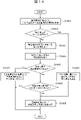
- FIG. 14 is a flowchart showing the processing contents of the control control device according to the third embodiment.
- the automatic guided vehicle instruction unit 313 receives the information on the toe position and the working device angle transmitted from the machine information management unit 112 (step S1401).
- the automatic guided vehicle instruction unit 313 determines whether or not the loading machine 10 is in the unloading posture (for example, the posture of opening the bucket) based on the received working device angle (step S1402).
- the loading machine 10 is a backhoe
- the automatic guided vehicle instruction unit 313 determines that the vehicle is in the unloading posture when the relative angle ⁇ 3 between the bucket and the arm is equal to or greater than a preset angle threshold value.
- the angle of the opening of the automatic guided vehicle indicating unit 313 is a predetermined threshold value.
- step S1402 When it is determined in step S1402 that the loading machine 10 is in the unloading posture, the automatic guided vehicle instruction unit 313 is closest to the toe position of the loading machine 10 in the same manner as in step S802 described in the first embodiment.
- the unmanned vehicle 20 in the loading completed state is extracted (step S1403).
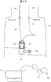
- FIG. 15 is a diagram for explaining the situation after the loading work is completed for the automatic guided vehicle by the loading machine.
- the loading machine 10 completes the loading operation for the unmanned vehicle 20, and the operator does not operate the instruction input device 15, that is, does not give a start instruction to the unmanned vehicle 20, and the toe position.
- the situation where 103 is moved to the outside of the loading area 203 of the automatic guided vehicle 20 is shown.
- the lower part of FIG. 15 is a diagram for explaining the state of the loading machine that gives a start instruction to the automatic guided vehicle.
- the loading machine 10 is in a posture in which the relative angle ⁇ 3 between the bucket and the arm is set to an angle threshold value or more (for example, 25 degrees or more, which is close to 30 degrees when fully opened).
- the automatic guided vehicle instruction unit 313 determines that the loading machine 10 is in the unloading posture (step S1402), and extracts the automatic guided vehicle 20 in the loading completed state closest to the toe position 103 (step S1403). Subsequently, the unmanned vehicle instruction unit 313 gives a start instruction to the extracted vehicle (step S1409).
- step S1402 when it is determined in step S1402 that the loading machine 10 is not in the unloading posture, the automatic guided vehicle instruction unit 313 is an automatic guided vehicle existing around the loading machine 10 as in step S802 described in the first embodiment. Is extracted (step S1404). Steps S1405 to S1409 following step S1404 are subjected to the same processing as steps S803 to S807 described in the first embodiment, respectively.
- the same operation and effect as those of the first embodiment can be obtained, and further, the following operation and effect can be obtained. That is, even if the operator forgets to input to the instruction input device 15 for giving a start instruction after the loading work is completed, the automatic guided vehicle instruction unit 313 is the loading machine based on the relative angle ⁇ 3 between the bucket and the arm. When it is determined that 10 is in the unloading posture, a start instruction is given to the unmanned vehicle 20. For this reason, the operator does not have to return the toe position to the loading area of the automatic guided vehicle 20, but only takes the unloading posture on the spot, in other words, only performs the minimum operation such as opening the bucket. It is possible to reliably give a start instruction to the unmanned vehicle 20.
- the vehicle information management unit and the autonomous travel control unit do not necessarily have to be provided in the unmanned vehicle, and may be provided in, for example, an external server device configured to be able to communicate with the unmanned vehicle and the control station, respectively.
- the toe position calculation unit and the machine information management unit do not necessarily have to be provided in the loading machine, and may be provided in, for example, an external server device configured to be able to communicate with the loading machine and the control station, respectively.
- Vehicle management system 10 Loading machine 11 Loading machine information management device 12 Loading machine position sensor 13 Loading machine orientation sensor 14 Working device angle sensor 15 Instruction input device 16 Loading machine wireless communication device 20 Unmanned vehicle 21 Unmanned vehicle control Device 22 Driving drive device 23 Unmanned vehicle position sensor 24 Unmanned vehicle orientation sensor 25 Loading sensor 26 Unmanned vehicle storage device 27 Unmanned vehicle wireless communication device 28 Loading platform 29 Canopy 30 Control station 31 Control control device 32 Control station storage device 33 Control station wireless communication Device 40 Wireless communication line 111 Toe position calculation unit 112 Machine information management unit 211 Vehicle information management unit 212 Autonomous driving control unit 261 Map information storage unit 311 Vehicle allocation management unit 312 Control control unit 313 Unmanned vehicle instruction unit 321 Vehicle allocation management information storage unit 322 Control information storage unit 323 Map information storage unit
Landscapes
- Engineering & Computer Science (AREA)
- Combustion & Propulsion (AREA)
- Transportation (AREA)
- Mechanical Engineering (AREA)
- Chemical & Material Sciences (AREA)
- Remote Sensing (AREA)
- Radar, Positioning & Navigation (AREA)
- Physics & Mathematics (AREA)
- General Physics & Mathematics (AREA)
- Automation & Control Theory (AREA)
- Business, Economics & Management (AREA)
- Aviation & Aerospace Engineering (AREA)
- Structural Engineering (AREA)
- General Engineering & Computer Science (AREA)
- Civil Engineering (AREA)
- Mining & Mineral Resources (AREA)
- Economics (AREA)
- Computing Systems (AREA)
- Development Economics (AREA)
- General Business, Economics & Management (AREA)
- Operations Research (AREA)
- Quality & Reliability (AREA)
- Entrepreneurship & Innovation (AREA)
- Human Resources & Organizations (AREA)
- Marketing (AREA)
- Accounting & Taxation (AREA)
- Strategic Management (AREA)
- Tourism & Hospitality (AREA)
- Theoretical Computer Science (AREA)
- Control Of Position, Course, Altitude, Or Attitude Of Moving Bodies (AREA)
- Navigation (AREA)
- Traffic Control Systems (AREA)
- Operation Control Of Excavators (AREA)
Abstract
Description
本願は、2020年11月6日に出願された日本国特願2020-185835号に基づき優先権を主張し、その内容をここに援用する。
図1は第1実施形態に係る車両管理システムを示す概略構成図である。図1に示すように、本実施形態の車両管理システム1は、露天掘り鉱山等の作業現場に用いられるシステムであり、掘削作業及び積込作業を行う1台以上の積込機械10と、積込機械10から積み込まれた土砂等を搬送する1台以上の無人車両20(無人車両20A、無人車両20B)と、無人車両20の配車管理及び交通管制を行う管制局30とを含む。積込機械10、無人車両20及び管制局30は、無線通信回線40によって互いに通信可能に構成されている。具体的には、露天掘り鉱山内等には複数の無線基地局41が設置されており、積込機械10、無人車両20及び管制局30は、これらの無線基地局41を介して互いに送受信を行っている。
積込機械10は、バケットが多関節構造により取り付けられる機械である。本実施形態の積込機械10は、例えば機械本体に対して上下方向に回動自在に設けられた作業装置を備えた油圧ショベル等のバックホーであり、作業装置はブーム、アーム、バケット等を有する。なお、積込機械10は、油圧ショベルに限定されず、例えばホイールローダ等であっても良い。
無人車両20は、例えば管制局30の指示に基づいて自律走行可能なダンプトラックである。この無人車両20は、無人車両制御装置21、走行駆動装置22、無人車両位置センサ23、無人車両方位センサ24、積載センサ25、無人車両記憶装置26、及び無人車両無線通信装置27を備えている。
管制局30は、管制制御装置31、管制局記憶装置32、及び管制局無線通信装置33を備えている。管制局記憶装置32は、情報の読み書きが可能な不揮発性の記憶媒体であり、OS(Operating System)や各種の制御プログラム、アプリケーション・プログラム、データベース等が格納されている。そして、管制局記憶装置32は、配車管理情報記憶部321と、管制情報記憶部322と、地図情報記憶部323とを有する。
次に、図12及び図13を参照して車両管理システムの第2実施形態を説明する。第2実施形態の車両管理システムは、オペレータによる指示入力装置15への入力がない場合でも、爪先位置及び無人車両20の積込領域に基づいて無人車両20に対する発進指示が行われる点において、上述した第1実施形態と相違している。その他の構成や処理は第1実施形態と同様であるため、重複説明を省略する。以下では、その相違点のみを説明する。
次に、図14及び図15を参照して車両管理システムの第3実施形態を説明する。第3実施形態の車両管理システムは、仮にオペレータが積込作業完了後に発進指示を行うための指示入力装置15への入力を忘れた場合でも、発進指示が確実に行われる点において、上述した第1実施形態と相違している。その他の構成や処理は第1実施形態と同様であるため、重複説明を省略する。以下では、その相違点のみを説明する。
10 積込機械
11 積込機械情報管理装置
12 積込機械位置センサ
13 積込機械方位センサ
14 作業装置角度センサ
15 指示入力装置
16 積込機械無線通信装置
20 無人車両
21 無人車両制御装置
22 走行駆動装置
23 無人車両位置センサ
24 無人車両方位センサ
25 積載センサ
26 無人車両記憶装置
27 無人車両無線通信装置
28 荷台
29 キャノピ
30 管制局
31 管制制御装置
32 管制局記憶装置
33 管制局無線通信装置
40 無線通信回線
111 爪先位置算出部
112 機械情報管理部
211 車両情報管理部
212 自律走行制御部
261 地図情報記憶部
311 配車管理部
312 管制制御部
313 無人車両指示部
321 配車管理情報記憶部
322 管制情報記憶部
323 地図情報記憶部
Claims (7)
- 自律走行可能な無人車両と、バケットが多関節構造により取り付けられるとともに前記無人車両に対して積込作業を行う積込機械と、前記無人車両の配車管理及び交通管制を行う管制局と、が互いに通信可能に構成された車両管理システムであって、
前記無人車両の位置、方位及び荷台寸法の情報を取得して記憶するとともにこれらの情報を前記管制局に送信する車両情報管理部と、
前記管制局からの指示に基づいて該無人車両の走行を制御する自律走行制御部と、
前記積込機械の位置、方位及び各関節の角度の情報に基づいて前記バケットの爪先位置を算出する爪先位置算出部と、
前記爪先位置算出部により算出された前記爪先位置を取得して記憶するとともに該爪先位置の情報を前記管制局に送信する機械情報管理部と、
前記車両情報管理部から送信された前記無人車両の位置、方位及び荷台寸法の情報に基づいて前記無人車両の積込領域を算出し、算出した前記積込領域と前記機械情報管理部から送信された前記爪先位置とに基づいて、前記無人車両に対する呼込指示又は発進指示を行う無人車両指示部と、
を備えることを特徴とする車両管理システム。 - 前記無人車両指示部は、前記爪先位置が前記無人車両の積込領域内に存在しない場合に前記無人車両に対する呼込指示を行う請求項1に記載の車両管理システム。
- 前記無人車両指示部は、前記爪先位置が前記無人車両の積込領域内に存在し、且つ前記無人車両の積載量に基づいて該無人車両が積込完了状態であると判定した場合に、前記無人車両に対する発進指示を行う請求項2に記載の車両管理システム。
- 前記積込機械は、オペレータが前記無人車両に対する指示を入力する指示入力装置を更に備え、
前記機械情報管理部は、前記指示入力装置に指示入力があった場合に、該指示入力に応じて前記無人車両への動作指示情報を更に生成し、生成した動作指示情報を前記爪先位置の情報とともに前記管制局に送信する請求項1~3のいずれか一項に記載の車両管理システム。 - 前記無人車両指示部は、前記爪先位置が前記無人車両の積込領域内に存在し、且つ前記爪先位置が前記積込機械から離反方向への移動回数に基づいて前記積込機械の積込動作を必要積込回数以上実施したと判定した場合に、前記無人車両に対する発進指示を行う請求項1に記載の車両管理システム。
- 前記無人車両指示部は、前記積込機械の前記バケットの容量及び前記無人車両の荷台の容量に基づいて、必要積込回数を設定する請求項5に記載の車両管理システム。
- 前記機械情報管理部は、前記各関節の角度の情報を更に取得して記憶するとともに該各関節の角度の情報を管制局に送信し、
前記無人車両指示部は、前記各関節の角度の情報に基づいて前記積込機械が荷下ろし姿勢であると判定した場合に、前記爪先位置に最も近い無人車両に対して発進指示を行う請求項1~3のいずれか一項に記載の車両管理システム。
Priority Applications (6)
| Application Number | Priority Date | Filing Date | Title |
|---|---|---|---|
| EP21889240.4A EP4242997A4 (en) | 2020-11-06 | 2021-11-04 | VEHICLE MANAGEMENT SYSTEM |
| CA3190387A CA3190387A1 (en) | 2020-11-06 | 2021-11-04 | Vehicle management system |
| CN202180052725.3A CN116057596B (zh) | 2020-11-06 | 2021-11-04 | 车辆管理系统 |
| US18/023,817 US12346126B2 (en) | 2020-11-06 | 2021-11-04 | Vehicle management system |
| AU2021375694A AU2021375694A1 (en) | 2020-11-06 | 2021-11-04 | Vehicle management system |
| AU2024266872A AU2024266872A1 (en) | 2020-11-06 | 2024-11-25 | Vehicle management system |
Applications Claiming Priority (2)
| Application Number | Priority Date | Filing Date | Title |
|---|---|---|---|
| JP2020-185835 | 2020-11-06 | ||
| JP2020185835A JP7137605B2 (ja) | 2020-11-06 | 2020-11-06 | 車両管理システム |
Publications (1)
| Publication Number | Publication Date |
|---|---|
| WO2022097688A1 true WO2022097688A1 (ja) | 2022-05-12 |
Family
ID=81458363
Family Applications (1)
| Application Number | Title | Priority Date | Filing Date |
|---|---|---|---|
| PCT/JP2021/040641 Ceased WO2022097688A1 (ja) | 2020-11-06 | 2021-11-04 | 車両管理システム |
Country Status (7)
| Country | Link |
|---|---|
| US (1) | US12346126B2 (ja) |
| EP (1) | EP4242997A4 (ja) |
| JP (1) | JP7137605B2 (ja) |
| CN (1) | CN116057596B (ja) |
| AU (2) | AU2021375694A1 (ja) |
| CA (1) | CA3190387A1 (ja) |
| WO (1) | WO2022097688A1 (ja) |
Cited By (1)
| Publication number | Priority date | Publication date | Assignee | Title |
|---|---|---|---|---|
| WO2025204941A1 (ja) * | 2024-03-28 | 2025-10-02 | 株式会社小松製作所 | システム、作業機械、および制御方法 |
Families Citing this family (5)
| Publication number | Priority date | Publication date | Assignee | Title |
|---|---|---|---|---|
| JP7404170B2 (ja) * | 2020-06-25 | 2023-12-25 | 株式会社小松製作所 | 作業機械の方位を較正するためのシステムおよび方法 |
| JP7580423B2 (ja) * | 2022-04-22 | 2024-11-11 | 株式会社小松製作所 | 作業現場の管理システム及び作業現場の管理方法 |
| JP7746224B2 (ja) | 2022-06-28 | 2025-09-30 | 株式会社クボタ | 旋回作業機、及び旋回作業機の方位検出方法 |
| JP2024043780A (ja) * | 2022-09-20 | 2024-04-02 | 株式会社小松製作所 | 作業機械を含むシステム、および作業機械の制御方法 |
| JP2024102615A (ja) * | 2023-01-19 | 2024-07-31 | 株式会社小松製作所 | 作業現場の管理システム及び作業現場の管理方法 |
Citations (6)
| Publication number | Priority date | Publication date | Assignee | Title |
|---|---|---|---|---|
| JPH08263138A (ja) * | 1995-03-24 | 1996-10-11 | Komatsu Ltd | 無人ダンプ走行コースデータ作成方法及び作成装置 |
| JP2016193691A (ja) * | 2015-04-01 | 2016-11-17 | 日立建機株式会社 | ダンプトラックの積込場路面状態検知システム |
| US9823082B2 (en) | 2011-08-24 | 2017-11-21 | Modular Mining Systems, Inc. | Driver guidance for guided maneuvering |
| WO2018155709A1 (ja) * | 2017-02-27 | 2018-08-30 | 日立建機株式会社 | ダンプトラック及び後退支援装置 |
| JP2019200462A (ja) | 2018-05-14 | 2019-11-21 | 日立建機株式会社 | 車両管制システム |
| JP2020185835A (ja) | 2019-05-10 | 2020-11-19 | 日本発條株式会社 | シート開口部の目隠し構造。 |
Family Cites Families (16)
| Publication number | Priority date | Publication date | Assignee | Title |
|---|---|---|---|---|
| JP2711612B2 (ja) * | 1992-04-20 | 1998-02-10 | 株式会社フジタ | 土工事の自動搬送システム |
| AU2002344089B2 (en) * | 2001-10-18 | 2006-06-22 | Hitachi Construction Machinery Co., Ltd. | Hydraulic shovel work amount detection apparatus, work amount detection method, work amount detection result display apparatus |
| US20090216410A1 (en) | 2008-02-26 | 2009-08-27 | William Edward Allen | Automated machine management system with destination selection |
| US20120136507A1 (en) * | 2010-11-30 | 2012-05-31 | Caterpillar Inc. | System and Method for Controlling a Machine at a Worksite |
| JP5596661B2 (ja) * | 2011-11-11 | 2014-09-24 | 株式会社小松製作所 | 鉱山機械の管理システム及び鉱山機械の管理システムの管理方法 |
| JP6001196B2 (ja) * | 2013-12-09 | 2016-10-05 | 日立建機株式会社 | 行動指示システム及び方法 |
| CN105518556B (zh) * | 2013-12-12 | 2018-08-28 | 日立建机株式会社 | 车辆行驶系统以及车辆行驶控制方法 |
| US9523180B2 (en) * | 2014-04-28 | 2016-12-20 | Deere & Company | Semi-automatic material loading |
| US10635112B2 (en) * | 2017-03-31 | 2020-04-28 | Komatsu Ltd | Control system for work vehicle, work vehicle, and control method for work vehicle |
| JP7202064B2 (ja) * | 2017-10-04 | 2023-01-11 | 株式会社小松製作所 | 作業機械制御装置および制御方法 |
| CN108646754B (zh) * | 2018-06-30 | 2021-03-30 | 汤苏扬 | 一种智能小车控制系统 |
| CN109399254B (zh) * | 2018-12-07 | 2021-10-15 | 三一汽车制造有限公司 | 成品仓自动卸料控制系统及沥青站 |
| JP2021025271A (ja) * | 2019-08-02 | 2021-02-22 | コベルコ建機株式会社 | 作業機 |
| CN110745583B (zh) * | 2019-10-31 | 2021-03-16 | 三一汽车制造有限公司 | 车辆装料的自动定位系统与沥青站 |
| CN111137325B (zh) * | 2019-12-30 | 2022-04-29 | 北京易控智驾科技有限公司 | 一种矿区无人驾驶系统装载位的标定装置和方法 |
| US11892836B2 (en) * | 2020-01-27 | 2024-02-06 | Liebherr Mining Equipment Newport News Co. | System for controlling a plurality of autonomous vehicles on a mine site |
-
2020
- 2020-11-06 JP JP2020185835A patent/JP7137605B2/ja active Active
-
2021
- 2021-11-04 US US18/023,817 patent/US12346126B2/en active Active
- 2021-11-04 EP EP21889240.4A patent/EP4242997A4/en active Pending
- 2021-11-04 WO PCT/JP2021/040641 patent/WO2022097688A1/ja not_active Ceased
- 2021-11-04 CN CN202180052725.3A patent/CN116057596B/zh active Active
- 2021-11-04 CA CA3190387A patent/CA3190387A1/en active Pending
- 2021-11-04 AU AU2021375694A patent/AU2021375694A1/en not_active Abandoned
-
2024
- 2024-11-25 AU AU2024266872A patent/AU2024266872A1/en active Pending
Patent Citations (6)
| Publication number | Priority date | Publication date | Assignee | Title |
|---|---|---|---|---|
| JPH08263138A (ja) * | 1995-03-24 | 1996-10-11 | Komatsu Ltd | 無人ダンプ走行コースデータ作成方法及び作成装置 |
| US9823082B2 (en) | 2011-08-24 | 2017-11-21 | Modular Mining Systems, Inc. | Driver guidance for guided maneuvering |
| JP2016193691A (ja) * | 2015-04-01 | 2016-11-17 | 日立建機株式会社 | ダンプトラックの積込場路面状態検知システム |
| WO2018155709A1 (ja) * | 2017-02-27 | 2018-08-30 | 日立建機株式会社 | ダンプトラック及び後退支援装置 |
| JP2019200462A (ja) | 2018-05-14 | 2019-11-21 | 日立建機株式会社 | 車両管制システム |
| JP2020185835A (ja) | 2019-05-10 | 2020-11-19 | 日本発條株式会社 | シート開口部の目隠し構造。 |
Non-Patent Citations (1)
| Title |
|---|
| See also references of EP4242997A4 |
Cited By (1)
| Publication number | Priority date | Publication date | Assignee | Title |
|---|---|---|---|---|
| WO2025204941A1 (ja) * | 2024-03-28 | 2025-10-02 | 株式会社小松製作所 | システム、作業機械、および制御方法 |
Also Published As
| Publication number | Publication date |
|---|---|
| CN116057596B (zh) | 2025-10-17 |
| EP4242997A4 (en) | 2024-10-30 |
| CA3190387A1 (en) | 2022-05-12 |
| US20230324928A1 (en) | 2023-10-12 |
| JP2022075200A (ja) | 2022-05-18 |
| AU2021375694A1 (en) | 2023-03-16 |
| US12346126B2 (en) | 2025-07-01 |
| JP7137605B2 (ja) | 2022-09-14 |
| CN116057596A (zh) | 2023-05-02 |
| EP4242997A1 (en) | 2023-09-13 |
| AU2024266872A1 (en) | 2024-12-12 |
Similar Documents
| Publication | Publication Date | Title |
|---|---|---|
| JP7137605B2 (ja) | 車両管理システム | |
| JP7404414B2 (ja) | 作業機械制御装置および制御方法 | |
| JP7689159B2 (ja) | 作業システム、制御方法および積込機械制御装置 | |
| JP6267090B2 (ja) | 運搬車両の走行停止制御装置およびそれを備えた運搬車両 | |
| JP2020143481A (ja) | 自動運転作業機械 | |
| JP7058100B2 (ja) | 制御装置および制御方法 | |
| US20240301657A1 (en) | Travel system for work machine and method for controlling work machine | |
| US7191060B2 (en) | Method for automatically guiding a mining machine | |
| KR102423054B1 (ko) | 자율 주행 방법 및 이를 이용하는 무인 도저 | |
| JP2021162899A (ja) | 運搬車両の自動運転方法 | |
| AU2022451414B2 (en) | Vehicle management system | |
| KR102520923B1 (ko) | 건설 기계의 상태 예측 방법 | |
| AU2023475304A1 (en) | Method and system for autonomously operating a mining and/or construction machine | |
| WO2025047812A1 (ja) | 積込機械の制御システム、積込機械の制御方法および積込機械の遠隔操作システム | |
| WO2025047789A1 (ja) | 積込機械の制御システム、積込機械の制御方法および積込機械の遠隔操作システム | |
| WO2025052756A1 (ja) | 作業機械 |
Legal Events
| Date | Code | Title | Description |
|---|---|---|---|
| 121 | Ep: the epo has been informed by wipo that ep was designated in this application |
Ref document number: 21889240 Country of ref document: EP Kind code of ref document: A1 |
|
| ENP | Entry into the national phase |
Ref document number: 3190387 Country of ref document: CA |
|
| ENP | Entry into the national phase |
Ref document number: 2021375694 Country of ref document: AU Date of ref document: 20211104 Kind code of ref document: A |
|
| NENP | Non-entry into the national phase |
Ref country code: DE |
|
| ENP | Entry into the national phase |
Ref document number: 2021889240 Country of ref document: EP Effective date: 20230606 |
|
| WWG | Wipo information: grant in national office |
Ref document number: 18023817 Country of ref document: US |
|
| WWG | Wipo information: grant in national office |
Ref document number: 202180052725.3 Country of ref document: CN |