WO2022097705A1 - 食品加工装置 - Google Patents
食品加工装置 Download PDFInfo
- Publication number
- WO2022097705A1 WO2022097705A1 PCT/JP2021/040699 JP2021040699W WO2022097705A1 WO 2022097705 A1 WO2022097705 A1 WO 2022097705A1 JP 2021040699 W JP2021040699 W JP 2021040699W WO 2022097705 A1 WO2022097705 A1 WO 2022097705A1
- Authority
- WO
- WIPO (PCT)
- Prior art keywords
- reaction tube
- reaction
- tube
- food processing
- processing apparatus
- Prior art date
- Legal status (The legal status is an assumption and is not a legal conclusion. Google has not performed a legal analysis and makes no representation as to the accuracy of the status listed.)
- Ceased
Links
Images




Classifications
-
- C—CHEMISTRY; METALLURGY
- C12—BIOCHEMISTRY; BEER; SPIRITS; WINE; VINEGAR; MICROBIOLOGY; ENZYMOLOGY; MUTATION OR GENETIC ENGINEERING
- C12H—PASTEURISATION, STERILISATION, PRESERVATION, PURIFICATION, CLARIFICATION OR AGEING OF ALCOHOLIC BEVERAGES; METHODS FOR ALTERING THE ALCOHOL CONTENT OF FERMENTED SOLUTIONS OR ALCOHOLIC BEVERAGES
- C12H1/00—Pasteurisation, sterilisation, preservation, purification, clarification, or ageing of alcoholic beverages
- C12H1/12—Pasteurisation, sterilisation, preservation, purification, clarification, or ageing of alcoholic beverages without precipitation
- C12H1/16—Pasteurisation, sterilisation, preservation, purification, clarification, or ageing of alcoholic beverages without precipitation by physical means, e.g. irradiation
- C12H1/165—Pasteurisation, sterilisation, preservation, purification, clarification, or ageing of alcoholic beverages without precipitation by physical means, e.g. irradiation by irradiation
-
- A—HUMAN NECESSITIES
- A23—FOODS OR FOODSTUFFS; TREATMENT THEREOF, NOT COVERED BY OTHER CLASSES
- A23L—FOODS, FOODSTUFFS OR NON-ALCOHOLIC BEVERAGES, NOT OTHERWISE PROVIDED FOR; PREPARATION OR TREATMENT THEREOF
- A23L5/00—Preparation or treatment of foods or foodstuffs, in general; Food or foodstuffs obtained thereby; Materials therefor
- A23L5/30—Physical treatment, e.g. electrical or magnetic means, wave energy or irradiation
-
- B—PERFORMING OPERATIONS; TRANSPORTING
- B01—PHYSICAL OR CHEMICAL PROCESSES OR APPARATUS IN GENERAL
- B01J—CHEMICAL OR PHYSICAL PROCESSES, e.g. CATALYSIS OR COLLOID CHEMISTRY; THEIR RELEVANT APPARATUS
- B01J19/00—Chemical, physical or physico-chemical processes in general; Their relevant apparatus
- B01J19/08—Processes employing the direct application of electric or wave energy, or particle radiation; Apparatus therefor
- B01J19/12—Processes employing the direct application of electric or wave energy, or particle radiation; Apparatus therefor employing electromagnetic waves
- B01J19/122—Incoherent waves
- B01J19/123—Ultraviolet light
-
- A—HUMAN NECESSITIES
- A23—FOODS OR FOODSTUFFS; TREATMENT THEREOF, NOT COVERED BY OTHER CLASSES
- A23B—PRESERVATION OF FOODS, FOODSTUFFS OR NON-ALCOHOLIC BEVERAGES; CHEMICAL RIPENING OF FRUIT OR VEGETABLES
- A23B2/00—Preservation of foods or foodstuffs, in general
- A23B2/50—Preservation of foods or foodstuffs, in general by irradiation without heating
- A23B2/53—Preservation of foods or foodstuffs, in general by irradiation without heating with ultraviolet light
-
- A—HUMAN NECESSITIES
- A23—FOODS OR FOODSTUFFS; TREATMENT THEREOF, NOT COVERED BY OTHER CLASSES
- A23B—PRESERVATION OF FOODS, FOODSTUFFS OR NON-ALCOHOLIC BEVERAGES; CHEMICAL RIPENING OF FRUIT OR VEGETABLES
- A23B2/00—Preservation of foods or foodstuffs, in general
- A23B2/70—Preservation of foods or foodstuffs, in general by treatment with chemicals
Definitions
- This disclosure relates to food processing equipment.
- Patent Document 1 discloses a production method in which a photocatalyst is used in a food production process to sterilize microorganisms in a brewed product at room temperature without heating.
- Patent Document 1 there is room for improvement in the apparatus or manufacturing method of Patent Document 1 above. For example, there is a problem that it is difficult to effectively modify a reactant used in food.
- One aspect of the present disclosure is made in view of such circumstances, and provides a food processing apparatus capable of effectively modifying a reactant used in food.
- the food processing apparatus of one aspect of the present disclosure is arranged in the internal space, a reaction vessel having an internal space for storing a liquid reactant used for food, a cooling unit for cooling the reactant in the reaction vessel, and the internal space. It comprises a catalytic reaction section, the catalytic reaction section includes a reaction tube and a light source provided inside the reaction tube, a photocatalyst is provided on the outer surface of the reaction tube, and the reaction tube is from the light source. Through the irradiated light, the reaction tube has a first end, the first end is the bottom surface of the reaction tube, the first end is closed, and the inside of the reaction tube is dried. It is filled with gas.
- the computer-readable recording medium includes a non-volatile recording medium such as a CD-ROM (Compact Disc-Read Only Memory).
- the food processing apparatus of one aspect of the present disclosure can be operated stably, and the reactants used in the food can be effectively modified.
- FIG. 1 is a diagram showing an example of a food processing apparatus according to an embodiment.
- FIG. 2 is a diagram showing an example of the configuration of the catalytic reaction unit according to the first embodiment.
- FIG. 3 is a diagram showing an example of the configuration of the catalytic reaction unit according to the first modification of the first embodiment.
- FIG. 4 is a diagram showing an example of the configuration of the catalytic reaction unit according to the second modification of the first embodiment.
- FIG. 5 is a diagram showing an example of the configuration of the catalytic reaction unit according to the modified example 3 of the first embodiment.
- FIG. 6 is a functional block diagram of the food processing apparatus according to the third modification of the first embodiment.
- FIG. 7 is a flowchart showing an example of the operation of the food processing apparatus according to the third modification of the first embodiment.
- FIG. 8 is a diagram showing an example of the configuration of the catalytic reaction unit according to the second embodiment.
- FIG. 9 is a diagram showing a first example of the configuration of the catalytic reaction unit according to the third embodiment.
- FIG. 10 is a diagram showing a second example of the configuration of the catalytic reaction unit according to the third embodiment.
- FIG. 11 is a diagram showing a third example of the configuration of the catalytic reaction unit according to the third embodiment.
- a method for modifying food raw materials there is a method using a catalyst.
- a catalyst for example, in the production of margarine, there is a method using a nickel catalyst to hydrogenate the fat and oil component as a raw material.
- Using an immobilized enzyme in the production of food can also be one of the catalyst utilization.
- a catalyst may be used for the purpose of sterilization in the manufacturing process.
- a photocatalyst is used in the manufacturing process of food and brewed at room temperature without heating. A manufacturing method for sterilizing microorganisms in food is being studied.
- the conventional method using a catalyst is effective for modifying a single component raw material as a raw material used for food, but since it is an extension of a chemical engineering method, there are restrictions on the equipment configuration, making it versatile. There is room for improvement in order to accommodate the configuration suitable for the catalyst used in the development of.
- the equipment used in the conventional manufacturing method using a photocatalyst is also for sterilization purposes, there is room for improvement in order to support a configuration suitable for modifying food raw materials.
- a food processing apparatus that promotes a reaction in a reactant in contact with the outer surface of a reaction tube by irradiating the photocatalyst with light from the inside of a reaction tube provided with a photocatalyst on the outer surface, food is effectively used. It may be difficult to modify the raw material of. Due to the temperature difference between the reaction tube cooled by the cold reactant and the heat source, convection occurs in the gas inside the reaction tube, especially when the food processing equipment keeps the reactants at a low temperature.
- the present inventors have found a food processing apparatus in which the effect of promoting the reaction of a reactant by a photocatalyst is difficult to reduce.
- One aspect of the present disclosure is made in view of such circumstances, and provides a food processing apparatus using a photocatalyst that newly modifies a food material.
- the food processing apparatus is arranged in the internal space, a reaction vessel having an internal space for storing a liquid reactant used for food, a cooling unit for cooling the reactant in the reaction vessel, and the internal space.
- the catalytic reaction section includes a reaction tube and a light source provided inside the reaction tube, a photocatalyst is provided on the outer surface of the reaction tube, and the reaction tube is the light source.
- the reaction tube has a first end, the first end is the bottom surface of the reaction tube, the first end is closed, and the inside of the reaction tube is inside the reaction tube. It is filled with dry gas.
- the humidity inside the reaction tube can be set to a state lower than a predetermined humidity. Therefore, by cooling on the inner surface of the reaction tube, it is possible to suppress the occurrence of dew condensation on the inner surface of the reaction tube, and it is possible to irradiate the photocatalyst from the light source with light of a predetermined amount or more. As a result, the food processing apparatus can be operated stably, and the reactants used in the food can be effectively modified.
- the catalytic reaction section further has a second end sealed by a sealing section, and the second end may face the first end.
- the catalytic reaction unit may further have a discoloring member that is arranged inside the reaction tube and discolors when it comes into contact with moisture.
- the catalytic reaction unit may be further arranged inside the reaction tube and may have a moisture detection sensor for detecting moisture.
- the food reaction device can appropriately determine the mixing of water into the inside of the reaction tube as a physical quantity. Therefore, the food reaction apparatus can appropriately take measures against the occurrence of dew condensation inside the reaction tube.
- a control unit may be provided to stop the light emission of the light source.
- the food reaction apparatus stops the process of reacting the reactants when the effect of promoting the reaction of the reactants is reduced by the photocatalyst because the light source emits light when dew condensation occurs. can do. Therefore, it is possible to suppress the continuous operation of the food reaction device in a state where the reaction rate of the reactant is reduced, and it is possible to reduce the power consumption of the food reaction device.
- the catalytic reaction section is further arranged at the second end, and the pressure inside the reaction tube is increased by introducing a gas into the inside of the reaction tube or discharging the gas from the inside of the reaction tube.
- the second end may face the first end.
- the internal pressure of the reaction tube can be increased by introducing a gas inside the reaction tube or by providing a pressure adjusting unit for adjusting the pressure inside the reaction tube by discharging the gas from the inside of the reaction tube. It is possible to suppress the rise, and it is possible to suppress the intake of outside air into the inside of the reaction tube from the gap generated by the deformation of the structure. As a result, it is possible to suppress dew condensation on the inner surface of the reaction tube by cooling the outside air taken into the reaction tube.
- the catalytic reaction unit further includes an introduction tube for introducing a dry gas inside the reaction tube and a discharge tube for discharging the dry gas introduced by the introduction tube to the outside of the reaction tube. May be good.
- the distance between the introduction pipe and the first end is shorter than the distance between the introduction pipe and the second end, and the introduction pipe has an introduction port for introducing the dry gas into the inside of the reaction tube, and the discharge.
- the distance between the tube and the second end is shorter than the distance between the discharge tube and the first end, and the discharge tube may have a discharge port for discharging gas inside the reaction tube.
- the introduction port of the introduction tube is arranged at a position closer to one end than the other end of the reaction tube, and the discharge port of the discharge tube is arranged at a position closer to the other end than one end of the reaction tube.
- the dry gas can be introduced from one end of the reaction tube and the gas inside the reaction tube can be discharged from the other end. Therefore, it is possible to generate a flow of dry gas from the bottom surface to the opening inside the reaction tube, and the dry gas can be filled throughout the inside of the reaction tube.
- the catalytic reaction section is further arranged so as to be penetrated through the introduction tube, arranged around the introduction port of the introduction tube, and with a gap formed between the inside surface of the reaction tube and the introduction port. It may have a rectifying member.
- the dry gas introduced from the introduction port is rectified so as to flow in the vicinity of the inner surface of the reaction tube by the rectifying member. Therefore, it is possible to effectively suppress the formation of dew condensation on the inner surface of the reaction tube.
- the light source may include at least one of a fluorescent lamp that emits ultraviolet rays and an LED (Light Emitting Diode) that emits ultraviolet rays.
- a fluorescent lamp that emits ultraviolet rays
- an LED Light Emitting Diode
- FIG. 1 is a diagram showing an example of the food processing apparatus 100 of the embodiment.
- the food processing apparatus 100 includes a reaction tank 1, a stirring unit 2, a catalytic reaction unit 6, a cooling unit 10, and a reaction tank temperature detecting unit 11.
- the reaction tank 1 has a first space S1 for storing a liquid reactant used for food.
- the reaction vessel 1 is, for example, a bottomed cylindrical container.
- the reaction vessel 1 may be a bottomed tubular container having a first space S1 for storing a liquid reactant, and may not be cylindrical.
- the reaction tank 1 is provided with a lid portion 5 that closes the opening at the top of the reaction tank 1.
- the lid portion 5 is a disk-shaped member, and has a rotating shaft 3 of the stirring body 4, a plurality of catalytic reaction portions 6, and a through hole penetrated by the reaction tank temperature detecting portion 11.
- the stirring unit 2 has a stirring body 4 that stirs the reactants in the reaction tank 1 by rotating.
- the stirring unit 2 is arranged so that the rotating shaft 3 of the stirring unit 2 coincides with the central axis of the cylinder of the reaction tank 1.
- the stirring unit 2 includes a motor (not shown) that rotates the rotating shaft 3.
- the agitator 4 may be realized by, for example, an inclined paddle blade.
- the agitator 4 is one of a propeller blade, a disc turbine blade, and a centrifugal agitator so that the optimum processing conditions are taken in consideration of the operation processing conditions such as the viscosity of the reactant and the power consumption of the stirring unit 2. It may be realized by.
- the stirring body 4 should include at least one of an inclined paddle blade, a propeller blade, a disc turbine blade, and a centrifugal stirring body. good.
- a plurality of catalytic reaction units 6 are provided in the food processing apparatus 100.
- a plurality of (six in the present embodiment) catalytic reaction units 6 are spaced apart from each other around the rotating shaft 3 of the stirring body 4 when viewed from the axial direction of the rotating shaft 3 of the stirring body 4. Placed in.
- the outside of the six catalytic reaction units 6 is surrounded by the inner wall surface of the reaction tank 1. That is, the catalytic reaction unit 6 is arranged in the internal space S1 of the reaction tank 1.
- FIG. 2 is a diagram showing an example of the configuration of the catalytic reaction unit 6 according to the first embodiment.
- Each of the plurality of catalytic reaction units 6 has a reaction tube 7 and a light source 8 as shown in FIG. Even if the catalytic reaction section 6 further has a sealing section 13 that seals between the opening 7d at the end (the other end) opposite to the bottom surface 7c of the reaction tube 7 and the light source 8. good. As a result, the reaction tube 7 is sealed, and the airtightness inside the reaction tube 7 is maintained. The inside of the reaction tube 7 is filled with the dry gas 12.
- the reaction tube 7 has an outer surface provided with a photocatalyst and a bottom surface 7c having one end sealed, and transmits light. Specifically, the reaction tube 7 has a bottomed cylindrical glass base material 7a and a photocatalyst thin film 7b provided on the outer surface of the glass base material 7a.
- the glass base material 7a is arranged so that the cylindrical axial direction of the glass base material 7a is oriented along the rotation axis 3 of the stirring body 4.
- the photocatalyst thin film 7b provided on the outer surface of the glass substrate 7a is formed by, for example, a general sol-gel method.
- the thin film 7b of the photocatalyst is composed of TiO 2 .
- the sol-gel liquid used in the method for forming the thin film 7b of the photocatalyst is applied to the outer surface of the glass base material 7a, and the glass base material 7a to which the sol-gel liquid is applied is rotated by using a rotating machine. As a result, the sol-gel solution is uniformly applied over the entire outer surface of the glass substrate 7a.
- the glass base material 7a coated with the sol-gel liquid is dried in an electric furnace after the sol-gel liquid is dried, and then heated at a high temperature of 500 ° C. or higher, so that a thin film 7b of a photocatalyst is formed on the outer surface of the glass base material 7a. It is fired.
- the light source 8 irradiates the photocatalyst with light from the inside of the reaction tube 7.
- the light source 8 is inserted into the glass base material 7a from an open portion on the opposite side of the bottom surface 7c of the glass base material 7a.
- the light source 8 includes a light source having a center wavelength of about 260 nm to 400 nm in order to effectively generate excitons in the photocatalyst.
- the light source 8 includes, for example, a fluorescent lamp having a wavelength in the wavelength range (UV—A) of ultraviolet rays 315 nm to 400 nm as a central wavelength. Therefore, the reaction of the reactants by the photocatalyst can be effectively promoted.
- the light source 8 may be arranged so as to face the thin film 7b on the outer surface of the reaction tube 7 in order to effectively irradiate the thin film 7b provided on the outer surface of the glass substrate 7a with light.
- the light source 8 may include, for example, a high-pressure mercury lamp, an LED (Light Emitting Diode) that emits ultraviolet rays, and the like. Since the LED has high luminous efficiency and generates less heat, the strength of convection generated inside the reaction tube 7 can be reduced as compared with a light source having a large heat generation, and it is possible to suppress the intake of outside air into the reaction tube 7. Similarly, a fluorescent lamp that generates less heat may be used.
- the cooling unit 10 cools the reactants in the reaction tank 1.
- the cooling unit 10 is arranged so as to surround the outside of the plurality of catalytic reaction units 6.
- the cooling unit 10 has an outer wall 10a surrounding the reaction tank 1 and a cooling medium (refrigerant) flowing through the second space S2 between the reaction tank 1 and the outer wall 10a.
- the cooling unit 10 adjusts the temperature of the reactant by operating based on the temperature detected by the reaction tank temperature detecting unit 11. Specifically, when the reaction product having a temperature higher than the first temperature is cooled to the first temperature, the cooling unit 10 circulates a refrigerant having a temperature lower than the first temperature in the second space S2. As a result, the cooling unit 10 cools the reactant by exchanging heat between the refrigerant and the reactant with the reaction vessel 1 interposed therebetween.
- the refrigerant whose temperature has risen due to heat exchange with the reactant is cooled to the first temperature or lower in a heat exchanger (not shown) arranged outside the second space S2, and then returns to the second space S2. As shown above, they may be connected by a pipe (not shown).
- the refrigerant may be circulated between the second space S2 and the heat exchanger by, for example, a circulation pump (not shown). In this case, the cooling unit 10 may start cooling the reactants by starting the operation of the circulation pump.
- the reaction tank temperature detection unit 11 is arranged in the reaction tank 1 and detects the temperature of the reactants.
- the reaction tank temperature detection unit 11 is composed of, for example, a thermistor, a thermocouple, or the like.
- the reaction tank temperature detecting unit 11 penetrates the lid portion 5 and is fixed to the lid portion 5, for example.
- the food processing apparatus 100 starts the photocatalytic treatment. Specifically, in the photocatalytic treatment, the food processing apparatus 100 starts irradiating the thin film 7b of the photocatalyst from the inside of the reaction tube 7 by turning on the light source 8 of the catalytic reaction unit 6. In the photocatalytic treatment, the food processing apparatus 100 rotates the rotating shaft 3 of the stirring body 4 by driving the motor of the stirring unit 2, and agitates the reactants in the reaction tank 1. At the same time, in the photocatalytic treatment, the food processing apparatus 100 supplies the cooling medium to the second space S2 of the cooling unit 10 by driving the circulation pump of the cooling unit 10.
- the food processing apparatus 100 detects the temperature of the reaction product by the reaction tank temperature detection unit 11, and supplies the temperature of the cooling medium to the second space S2 so that the reaction product reaches a preset temperature, and the temperature of the cooling medium. / Or adjust the supply of cooling medium.
- the food processing apparatus 100 adjusts the temperature of the cooling medium by, for example, adjusting the amount of heat exchange in the heat exchanger installed outside the second space S2. Specifically, if the heat exchanger is air-cooled, the food processing apparatus 100 may adjust the temperature of the cooling medium by adjusting the air volume of the fan that promotes air cooling in the heat exchanger, or the heat exchanger.
- the temperature of the cooling medium may be adjusted by adjusting the amount of water by the pump that promotes water cooling in the heat exchanger.
- the food processing apparatus 100 supplies the cooling medium to the second space by adjusting the circulation amount by a circulation pump for circulating the cooling medium between the second space S2 outside the reaction tank 1 and the heat exchanger. The amount may be adjusted.
- the temperature of the cooling medium and / or the supply amount of the cooling medium can be adjusted by using a circulation device (not shown) including a heat exchanger, a circulation pump and piping.
- the reaction of the reactant in the food processing apparatus 100 is fermentation of brewer's yeast, it may be aged at a low temperature (for example, about 5 ° C.).
- the target preset temperature in the cooling unit 10 is 5 ° C.
- the photocatalyst irradiated with light is brought into contact with the reactant that is the raw material of the food, and the reactant is reformed by the photocatalyst.
- the fermentation period can be shortened by decomposing the sugar content in the wort in advance.
- the humidity of the gas inside the reaction tube 7 is lower than the predetermined humidity. can do. Therefore, by cooling on the inner surface of the reaction tube, it is possible to suppress the occurrence of dew condensation on the inner surface of the reaction tube, and it is possible to irradiate the photocatalyst from the light source with light of a predetermined amount or more. As a result, the food processing apparatus 100 can be operated stably, and the reactants used in the food can be effectively modified.
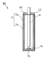
- FIG. 3 is a diagram showing an example of the configuration of the catalytic reaction unit 6a according to the first modification of the first embodiment.
- the catalytic reaction unit 6a may be configured such that the desiccant 14 is arranged inside the reaction tube 7. As a result, the inside of the reaction tube 7 is filled with the dry gas.
- the desiccant 14 may be, for example, silica gel.
- the catalytic reaction unit 6a may have the desiccant 14 arranged inside the reaction tube 7. This makes it possible to reduce the possibility of dew condensation.
- the inside of the reaction tube 7 may be filled with the dry gas 12 and the desiccant 14 may be arranged.
- the outside air containing water is discharged from the reaction tube 7 through minute gaps and / or gaps caused by material deformation. It may be mixed inside. As described above, even when the outside air containing water is mixed, the desiccant 14 is arranged inside the reaction tube 7, so that the possibility of dew condensation can be reduced.
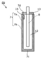
- FIG. 4 is a diagram showing an example of the configuration of the catalytic reaction unit 6b according to the second modification of the first embodiment.
- the catalytic reaction unit 6b according to the modified example 2 further includes a discoloring member 15 in the configuration of the catalytic reaction unit 6 according to the first embodiment.
- the discoloring member 15 is a member that is arranged inside the reaction tube 7 and discolors when it comes into contact with moisture.
- the discoloring member 15 is arranged, for example, on the inner surface of the reaction tube 7.
- the discoloring member 15 may be, for example, silica gel to which cobalt chloride is added, cobalt chloride paper, or the like.
- the operator of the food processing apparatus can visually and appropriately determine that water has been mixed in the reaction tube 7. Therefore, for example, the operator takes measures against the occurrence of dew condensation, such as replacing the reaction tube 7 in which the light from the light source 8 is difficult to reach the photocatalyst with the reaction tube 7 in which dew condensation does not occur. Can be made. Therefore, even if dew condensation occurs on the inner surface of the reaction tube 7, it is possible to irradiate the photocatalyst with light of a predetermined amount or more from the light source 8 from the light source.
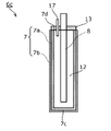
- FIG. 5 is a diagram showing an example of the configuration of the catalytic reaction unit 6c according to the modified example 3 of the first embodiment.
- FIG. 6 is a functional block diagram of the food processing apparatus 200 according to the third modification of the first embodiment.
- FIG. 7 is a flowchart showing an example of the operation of the food processing apparatus 200 according to the third modification of the first embodiment.
- the catalytic reaction unit 6c according to the modified example 3 further includes a moisture detection sensor 17 in the configuration of the catalytic reaction unit 6 according to the first embodiment.
- the moisture detection sensor 17 is arranged inside the reaction tube 7 and detects moisture.
- the moisture detection sensor 17 is provided at the end of a rod-shaped or linear member arranged in the sealing portion 13 through the sealing portion 13.
- the food processing apparatus 200 may include a control unit 16.
- the control unit 16 controls the operation of the food processing apparatus 200.
- the control unit 16 acquires the detection result of the moisture detection sensor 17, and controls at least one of the stirring unit 2, the light source 8, and the cooling unit 10 according to the acquired detection result. Even if the control unit 16 controls to stop the light emission of the light source 8, for example, when the moisture detection sensor 17 detects moisture, that is, when it is detected that moisture is generated inside the reaction tube 7. good.
- the control unit 16 may stop the operation of the stirring unit 2 and the operation of the cooling unit 10.
- the control unit 16 may be realized by, for example, a processor and a memory for storing a program executed by the processor.
- the control unit 16 may be realized by, for example, a dedicated circuit.
- control unit 16 starts the photocatalytic treatment (S11). Since the photocatalyst treatment is the same as the treatment described in the first embodiment, the description thereof will be omitted.
- control unit 16 determines whether or not moisture has been detected by the moisture detection sensor 17 (S12).
- the control unit 16 determines whether or not a predetermined time has elapsed since the photocatalyst treatment was started (S13). Specifically, the control unit 16 starts counting when the photocatalyst treatment is started, and by determining whether or not the count is equal to the predetermined time, a predetermined time has elapsed since the photocatalytic treatment was started. Judge whether or not.
- the predetermined time is a light emission time set in the photocatalyst treatment, and is stored in a memory (not shown) of the control unit 16.
- control unit 16 determines that moisture has been detected by the moisture detection sensor 17 (Yes in S12), or determines that a predetermined time has elapsed since the start of the photocatalyst treatment (Yes in S13), the control unit 16 performs the photocatalyst treatment. Stop (S14). When the control unit 16 determines that a predetermined time has not elapsed since the photocatalyst treatment was started (No in S13), the control unit 16 returns to step S12.
- the food processing apparatus 200 can appropriately determine the mixing of water into the inside of the reaction tube 7 as a physical quantity. Therefore, the food processing apparatus 200 can take measures against the occurrence of dew condensation inside the reaction tube 7. Specifically, the food processing apparatus 200 can control to stop the photocatalytic treatment as a countermeasure.
- the inside of the reaction tube 7 may be depressurized with the opening 7d of the reaction tube 7 sealed by the sealing portion 13.
- the inside of the reaction tube 7 may be a vacuum. As a result, it is possible to prevent the formation of dew condensation on the inner surface of the reaction tube 7.
- FIG. 8 is a diagram showing an example of the configuration of the catalytic reaction unit 6d according to the second embodiment.
- the food processing apparatus according to the second embodiment has a different configuration of the catalytic reaction unit 6d as compared with the food processing apparatus 100 according to the first embodiment, and the other configurations are the same. Therefore, the configuration of the catalytic reaction unit 6d will be described.
- the catalytic reaction unit 6d further includes a pressure adjusting unit 18 in the configuration of the catalytic reaction unit 6 according to the first embodiment.
- the pressure inside the reaction tube 7 is adjusted by introducing a gas into the pressure adjusting unit 18 and the reaction tube 7, or by discharging the gas from the inside of the reaction tube 7.
- the pressure adjusting portion 18 is arranged in the sealing portion 13 through the other end of the reaction tube 7, that is, the sealing portion 13.
- the pressure adjusting unit 18 is, for example, a pressure valve that externally regulates the pressure inside the reaction tube 7.
- the gas inside expands due to the heat generated when the light source 8 emits light, and the pressure inside the reaction tube 7 increases.
- the pressure adjusting section 18 can suppress the internal pressure of the reaction tube 7 from rising from a predetermined pressure, and the material of the sealing section 13 or the like is deformed. It is possible to suppress the generation of fine gaps. As a result, the possibility that the outside air is mixed inside the reaction tube 7 can be reduced.
- FIG. 9 is a diagram showing a first example of the configuration of the catalytic reaction unit 6e according to the third embodiment.
- FIG. 10 is a diagram showing a second example of the configuration of the catalytic reaction unit 6f according to the third embodiment.
- FIG. 11 is a diagram showing a third example of the configuration of the catalytic reaction unit 6 g according to the third embodiment. The arrows in the figure indicate the gas flow inside the reaction tube 7.
- the food processing apparatus according to the third embodiment has different configurations of the catalytic reaction units 6e, 6f, and 6g as compared with the food processing apparatus 100 according to the first embodiment, and the other configurations are the same. Therefore, the configurations of the catalytic reaction units 6e, 6f, and 6g will be described.
- the catalytic reaction unit 6e further includes an introduction pipe 19 and a discharge pipe 20 in the configuration of the catalytic reaction unit 6 according to the first embodiment.
- the introduction tube 19 is a tubular member that introduces a dry gas into the reaction tube 7.
- the discharge pipe 20 is a tubular member that discharges the dry gas introduced by the introduction pipe 19 to the outside of the reaction pipe 7.
- the introduction tube 19 is arranged at a position closer to the other end (opening 7d) than one end (bottom surface 7c) of the reaction tube 7, and has an introduction port 19a for introducing dry gas into the inside of the reaction tube 7.
- the discharge tube 20 is arranged at a position closer to the other end (opening 7d) than one end (bottom surface 7c) of the reaction tube 7, and has a discharge port 20a for discharging the gas inside the reaction tube 7. That is, the introduction port 19a and the discharge port 20a are arranged in the vicinity of the opening 7d of the reaction tube 7.
- the introduction pipe 19 and the discharge pipe 20 are arranged in the sealing portion 13 through the sealing portion 13.
- the introduction tube 19 and the discharge tube 20 are arranged at different positions of the sealing portion 13, for example, the introduction tube 19 is arranged on the side opposite to the discharge tube 20 with the light source 8 interposed therebetween.
- the gas inside the reaction tube 7 is replaced with the dry gas in order to release the gas inside the reaction tube 7 from the discharge tube 20 while introducing the dry gas from the introduction tube 19 into the inside of the reaction tube 7. be able to. Therefore, the state in which the inside of the reaction tube 7 is filled with the dry gas can be effectively maintained.
- the catalytic reaction section 6f has an introduction tube 19A instead of the introduction tube 19 of the catalytic reaction section 6e of the first example.
- the introduction pipe 19A is different from the introduction pipe 19 in that the length of the pipe is longer.
- the introduction tube 19A is arranged at a position closer to one end (bottom surface 7c) than the other end (opening 7d) of the reaction tube 7, and has an introduction port 19Aa for introducing dry gas into the inside of the reaction tube 7. That is, the introduction port 19Aa is arranged in the vicinity of the bottom surface 7c of the reaction tube 7.
- the dry gas can be introduced from the vicinity of one end (bottom surface 7c) of the reaction tube 7 and the gas inside the reaction tube 7 can be discharged from the vicinity of the other end (opening 7d). Therefore, it is possible to generate a flow of dry gas from the bottom surface 7c to the opening 7d inside the reaction tube 7, and the dry gas can be filled over the entire inside of the reaction tube 7.
- the catalytic reaction unit 6g further includes a rectifying member 21 in the configuration of the catalytic reaction unit 6f of the second example.
- the rectifying member 21 is a member that penetrates the introduction pipe 19A, is arranged around the introduction port 19Aa of the introduction pipe 19A, and is arranged in a state where a gap is formed between the rectifying member 21 and the inner surface of the reaction tube 7. be.
- the rectifying member 21 is, for example, a plate-shaped member, for example, a disk-shaped member.
- the rectifying member 21 may be penetrated by the light source 8. When the reaction tube 7 is viewed from above, the rectifying member 21 may be arranged in a state where a gap is formed between the entire circumference of the outer peripheral edge of the rectifying member 21 and the inner surface of the reaction tube 7.
- the dry gas introduced from the introduction port 19Aa of the introduction pipe 19A is rectified so as to flow in the vicinity of the inner surface of the reaction tube 7 by the rectifying member 21. Therefore, it is possible to effectively suppress the formation of dew condensation on the inner surface of the reaction tube 7.
- the food processing apparatus according to the third embodiment operates in the same manner as the food processing apparatus 100 according to the first embodiment, detailed description thereof will be omitted.
- the food processing apparatus has been described above based on the embodiment, but the present disclosure is not limited to this embodiment. As long as it does not deviate from the gist of the present disclosure, one or more of the present embodiments may be modified by those skilled in the art, or may be constructed by combining components in different embodiments. It may be included within the scope of the embodiment.
- One aspect of the present disclosure can be used, for example, in a food processing apparatus using a photocatalyst that modifies a raw material of food.
Landscapes
- Chemical & Material Sciences (AREA)
- Health & Medical Sciences (AREA)
- Engineering & Computer Science (AREA)
- Organic Chemistry (AREA)
- Life Sciences & Earth Sciences (AREA)
- Food Science & Technology (AREA)
- General Health & Medical Sciences (AREA)
- Toxicology (AREA)
- General Engineering & Computer Science (AREA)
- Wood Science & Technology (AREA)
- Zoology (AREA)
- Biochemistry (AREA)
- Bioinformatics & Cheminformatics (AREA)
- Genetics & Genomics (AREA)
- Chemical Kinetics & Catalysis (AREA)
- Electromagnetism (AREA)
- Physics & Mathematics (AREA)
- Nutrition Science (AREA)
- Polymers & Plastics (AREA)
- Food-Manufacturing Devices (AREA)
- Physical Or Chemical Processes And Apparatus (AREA)
- Catalysts (AREA)
- General Preparation And Processing Of Foods (AREA)
Abstract
Description
本発明者らは、「背景技術」の欄において記載した、食品の製造装置または製造方法に関し、以下の問題が生じることを見出した。
食品加工装置100の構成について、図1を用いて説明する。図1は、実施の形態の食品加工装置100の一例を示す図である。
(変形例1)
実施の形態1の変形例1について図3を用いて説明する。図3は、実施の形態1の変形例1に係る触媒反応部6aの構成の一例を示す図である。
実施の形態1の変形例2について図4を用いて説明する。図4は、実施の形態1の変形例2に係る触媒反応部6bの構成の一例を示す図である。
実施の形態1の変形例3について図5~図7を用いて説明する。図5は、実施の形態1の変形例3に係る触媒反応部6cの構成の一例を示す図である。図6は、実施の形態1の変形例3に係る食品加工装置200の機能ブロック図である。図7は、実施の形態1の変形例3に係る食品加工装置200の動作の一例を示すフローチャートである。
反応管7の内部は、反応管7の開口部7dが封止部13により封止された状態で、減圧されていてもよい。反応管7の内部は、真空であってもよい。これにより、反応管7の内面に結露が発生することを抑制することができる。
次に、実施の形態2における食品加工装置の触媒反応部について、図8を用いて説明する。図8は、実施の形態2に係る触媒反応部6dの構成の一例を示す図である。
次に、実施の形態3における食品加工装置の触媒反応部について、図9~図11を用いて説明する。図9は、実施の形態3に係る触媒反応部6eの構成の第1の例を示す図である。図10は、実施の形態3に係る触媒反応部6fの構成の第2の例を示す図である。図11は、実施の形態3に係る触媒反応部6gの構成の第3の例を示す図である。なお、図中における矢印は、反応管7の内部における気体の流れを示す。
2 撹拌部
3 回転軸
4 撹拌体
5 蓋部
6、6a~6g 触媒反応部
7 反応管
7a ガラス基材
7b 薄膜
7c 底面
7d 開口部
8 光源
10 冷却部
11 反応槽温度検知部
12 乾燥気体
13 封止部
14 乾燥剤
15 変色部材
16 制御部
17 水分検知センサ
18 圧力調整部
19、19A 導入管
20 放出管
21 整流部材
100、200 食品加工装置
Claims (10)
- 食品に用いる液状の反応物を貯める内部空間を有する反応槽と、
前記反応槽内の前記反応物を冷却する冷却部と、
前記内部空間に配置される触媒反応部と、を具備し、
前記触媒反応部は、反応管と前記反応管の内部に設けられた光源を含み、
前記反応管の外表面に光触媒が設けられ、
前記反応管は前記光源から照射された光を透過し、
前記反応管は第一端を有し、前記第一端は前記反応管の底面であり、前記第一端は閉じられており、
前記反応管の内部には乾燥気体が充填されている
食品加工装置。 - 前記反応管は封止部で封止された第二端を有し、前記第二端は前記第一端と対向する
請求項1に記載の食品加工装置。 - 前記触媒反応部は、さらに、前記反応管の内部に配置され、水分と接触することで変色する変色部材を有する
請求項1または2に記載の食品加工装置。 - 前記触媒反応部は、さらに、前記反応管の内部に配置され、水分を検知する水分検知センサを有する
請求項1から3のいずれか1項に記載の食品加工装置。 - さらに、
前記水分検知センサにより水分が検知された場合、前記光源の発光を停止させる制御部を備える
請求項4に記載の食品加工装置。 - 前記触媒反応部は、さらに、前記第二端に配置され、かつ、前記反応管の内部に気体を導入する、または、前記反応管の内部から気体を放出することで前記反応管の内部の圧力を調整する圧力調整部を備え、前記第二端は前記第一端と対向する
請求項1に記載の食品加工装置。 - 前記触媒反応部は、さらに、
前記反応管の内部に乾燥気体を導入する導入管と、
前記導入管により導入された前記乾燥気体を前記反応管の外部へ放出する放出管と、を有する
請求項1に記載の食品加工装置。 - 前記導入管と前記第一端の距離は、前記導入管と前記第二端の距離より短く、
前記導入管は、前記乾燥気体を前記反応管の内部に導入する導入口を有し、
前記放出管と前記第二端の距離は、前記放出管と前記第一端の距離より短く、
前記放出管は、前記反応管の内部の気体を放出する放出口を有する
請求項7に記載の食品加工装置。 - 前記触媒反応部は、さらに、前記導入管に貫通され、かつ、前記導入管の前記導入口の周囲に配置され、かつ、前記反応管の内面との間に隙間が形成された状態で配置される整流部材を有する、
請求項8に記載の食品加工装置。 - 前記光源は、紫外線を発光する蛍光灯および紫外線を発光するLED(Light Emitting Diode)の少なくとも1つを含む
請求項1から9のいずれか1項に記載の食品加工装置。
Priority Applications (4)
| Application Number | Priority Date | Filing Date | Title |
|---|---|---|---|
| JP2022560817A JP7249612B2 (ja) | 2020-11-05 | 2021-11-05 | 食品加工装置 |
| EP21889257.8A EP4241632A4 (en) | 2020-11-05 | 2021-11-05 | FOOD PROCESSING EQUIPMENT |
| CA3195164A CA3195164A1 (en) | 2020-11-05 | 2021-11-05 | Food processing apparatus |
| US18/301,257 US20230257685A1 (en) | 2020-11-05 | 2023-04-17 | Food processing apparatus |
Applications Claiming Priority (2)
| Application Number | Priority Date | Filing Date | Title |
|---|---|---|---|
| JP2020-185434 | 2020-11-05 | ||
| JP2020185434 | 2020-11-05 |
Related Child Applications (1)
| Application Number | Title | Priority Date | Filing Date |
|---|---|---|---|
| US18/301,257 Continuation US20230257685A1 (en) | 2020-11-05 | 2023-04-17 | Food processing apparatus |
Publications (1)
| Publication Number | Publication Date |
|---|---|
| WO2022097705A1 true WO2022097705A1 (ja) | 2022-05-12 |
Family
ID=81457964
Family Applications (1)
| Application Number | Title | Priority Date | Filing Date |
|---|---|---|---|
| PCT/JP2021/040699 Ceased WO2022097705A1 (ja) | 2020-11-05 | 2021-11-05 | 食品加工装置 |
Country Status (5)
| Country | Link |
|---|---|
| US (1) | US20230257685A1 (ja) |
| EP (1) | EP4241632A4 (ja) |
| JP (1) | JP7249612B2 (ja) |
| CA (1) | CA3195164A1 (ja) |
| WO (1) | WO2022097705A1 (ja) |
Cited By (1)
| Publication number | Priority date | Publication date | Assignee | Title |
|---|---|---|---|---|
| WO2023112588A1 (ja) * | 2021-12-13 | 2023-06-22 | パナソニックIpマネジメント株式会社 | 食品加工装置及び食品加工装置の運転方法 |
Citations (3)
| Publication number | Priority date | Publication date | Assignee | Title |
|---|---|---|---|---|
| JP2003250514A (ja) | 2002-03-01 | 2003-09-09 | Nippon Techno Kk | 醸造物の製造方法 |
| JP2015157284A (ja) * | 2009-10-05 | 2015-09-03 | 株式会社キッツ | 除菌浄化用水処理装置 |
| CN204958454U (zh) * | 2015-06-26 | 2016-01-13 | 徐州工程学院 | 有机废水光催化降解装置 |
Family Cites Families (4)
| Publication number | Priority date | Publication date | Assignee | Title |
|---|---|---|---|---|
| JP2004201535A (ja) * | 2002-12-24 | 2004-07-22 | Kyushu Kankyo Techno Kk | 保存性および香味の優れた醸造食品の製造方法、並びに該方法に使用する発酵済み醸造食品の殺菌処理装置 |
| WO2018026008A1 (ja) * | 2016-08-05 | 2018-02-08 | 株式会社トクヤマ | 紫外線殺菌方法及び紫外線殺菌装置 |
| CN211339459U (zh) * | 2019-11-05 | 2020-08-25 | 福建创新食品科技有限公司 | 一种发酵调味品专用发酵装置 |
| CN211734294U (zh) * | 2019-11-05 | 2020-10-23 | 华南农业大学 | 一种降解花生油黄曲霉毒素的光催化反应装置 |
-
2021
- 2021-11-05 JP JP2022560817A patent/JP7249612B2/ja active Active
- 2021-11-05 CA CA3195164A patent/CA3195164A1/en active Pending
- 2021-11-05 WO PCT/JP2021/040699 patent/WO2022097705A1/ja not_active Ceased
- 2021-11-05 EP EP21889257.8A patent/EP4241632A4/en not_active Withdrawn
-
2023
- 2023-04-17 US US18/301,257 patent/US20230257685A1/en active Pending
Patent Citations (3)
| Publication number | Priority date | Publication date | Assignee | Title |
|---|---|---|---|---|
| JP2003250514A (ja) | 2002-03-01 | 2003-09-09 | Nippon Techno Kk | 醸造物の製造方法 |
| JP2015157284A (ja) * | 2009-10-05 | 2015-09-03 | 株式会社キッツ | 除菌浄化用水処理装置 |
| CN204958454U (zh) * | 2015-06-26 | 2016-01-13 | 徐州工程学院 | 有机废水光催化降解装置 |
Non-Patent Citations (1)
| Title |
|---|
| See also references of EP4241632A4 |
Cited By (1)
| Publication number | Priority date | Publication date | Assignee | Title |
|---|---|---|---|---|
| WO2023112588A1 (ja) * | 2021-12-13 | 2023-06-22 | パナソニックIpマネジメント株式会社 | 食品加工装置及び食品加工装置の運転方法 |
Also Published As
| Publication number | Publication date |
|---|---|
| US20230257685A1 (en) | 2023-08-17 |
| JPWO2022097705A1 (ja) | 2022-05-12 |
| JP7249612B2 (ja) | 2023-03-31 |
| EP4241632A1 (en) | 2023-09-13 |
| CA3195164A1 (en) | 2022-05-12 |
| EP4241632A4 (en) | 2024-04-17 |
Similar Documents
| Publication | Publication Date | Title |
|---|---|---|
| WO2022097668A1 (ja) | 食品加工装置及び光源付き反応管 | |
| JP5249419B2 (ja) | 反応装置 | |
| US20240306676A1 (en) | Food processing apparatus and method of operating food processing apparatus | |
| JP2010154792A (ja) | Co2インキュベータ | |
| JP7249612B2 (ja) | 食品加工装置 | |
| US20250185675A1 (en) | Food processing apparatus and method of operating food processing apparatus | |
| JP7220367B2 (ja) | 食品加工装置 | |
| US20230332078A1 (en) | Food processing apparatus and method for operating food processing apparatus | |
| JP7249613B2 (ja) | 食品加工装置の運転方法、及び、食品加工装置 | |
| CN105056859B (zh) | 一种旋转式生化反应箱 | |
| CN220900367U (zh) | 预缩聚反应器 | |
| US20230240338A1 (en) | Food processing device | |
| CN220450194U (zh) | 一种抑制香精霉菌发酵装置 | |
| JP7270146B2 (ja) | 食品加工装置 | |
| CN205109618U (zh) | 一种旋转式生化反应箱 | |
| JP3991974B2 (ja) | 有機廃棄物処理装置 | |
| CN219894532U (zh) | 一种嘉宝果饮料的巴氏杀菌装置 | |
| CN210187170U (zh) | 一种低功耗转化罐 | |
| JP2022034237A (ja) | 液封式真空ポンプおよび滅菌処理方法 | |
| JP2024155133A (ja) | 光照射装置、及び光処理方法 | |
| JP2003062543A (ja) | 生ごみ処理装置 | |
| JP2005138089A (ja) | 含水率測定方法 | |
| JP2003290747A (ja) | 廃棄物処理装置 |
Legal Events
| Date | Code | Title | Description |
|---|---|---|---|
| 121 | Ep: the epo has been informed by wipo that ep was designated in this application |
Ref document number: 21889257 Country of ref document: EP Kind code of ref document: A1 |
|
| ENP | Entry into the national phase |
Ref document number: 2022560817 Country of ref document: JP Kind code of ref document: A |
|
| ENP | Entry into the national phase |
Ref document number: 3195164 Country of ref document: CA |
|
| NENP | Non-entry into the national phase |
Ref country code: DE |
|
| ENP | Entry into the national phase |
Ref document number: 2021889257 Country of ref document: EP Effective date: 20230605 |
|
| WWW | Wipo information: withdrawn in national office |
Ref document number: 2021889257 Country of ref document: EP |