WO2022100403A1 - 球囊导管 - Google Patents
球囊导管 Download PDFInfo
- Publication number
- WO2022100403A1 WO2022100403A1 PCT/CN2021/125445 CN2021125445W WO2022100403A1 WO 2022100403 A1 WO2022100403 A1 WO 2022100403A1 CN 2021125445 W CN2021125445 W CN 2021125445W WO 2022100403 A1 WO2022100403 A1 WO 2022100403A1
- Authority
- WO
- WIPO (PCT)
- Prior art keywords
- balloon catheter
- distal end
- inner tube
- outer diameter
- transition
- Prior art date
- Legal status (The legal status is an assumption and is not a legal conclusion. Google has not performed a legal analysis and makes no representation as to the accuracy of the status listed.)
- Ceased
Links
Images


Classifications
-
- A—HUMAN NECESSITIES
- A61—MEDICAL OR VETERINARY SCIENCE; HYGIENE
- A61M—DEVICES FOR INTRODUCING MEDIA INTO, OR ONTO, THE BODY; DEVICES FOR TRANSDUCING BODY MEDIA OR FOR TAKING MEDIA FROM THE BODY; DEVICES FOR PRODUCING OR ENDING SLEEP OR STUPOR
- A61M25/00—Catheters; Hollow probes
- A61M25/10—Balloon catheters
- A61M25/1006—Balloons formed between concentric tubes
-
- A—HUMAN NECESSITIES
- A61—MEDICAL OR VETERINARY SCIENCE; HYGIENE
- A61M—DEVICES FOR INTRODUCING MEDIA INTO, OR ONTO, THE BODY; DEVICES FOR TRANSDUCING BODY MEDIA OR FOR TAKING MEDIA FROM THE BODY; DEVICES FOR PRODUCING OR ENDING SLEEP OR STUPOR
- A61M25/00—Catheters; Hollow probes
- A61M25/0021—Catheters; Hollow probes characterised by the form of the tubing
- A61M25/0023—Catheters; Hollow probes characterised by the form of the tubing by the form of the lumen, e.g. cross-section, variable diameter
- A61M25/0026—Multi-lumen catheters with stationary elements
-
- A—HUMAN NECESSITIES
- A61—MEDICAL OR VETERINARY SCIENCE; HYGIENE
- A61M—DEVICES FOR INTRODUCING MEDIA INTO, OR ONTO, THE BODY; DEVICES FOR TRANSDUCING BODY MEDIA OR FOR TAKING MEDIA FROM THE BODY; DEVICES FOR PRODUCING OR ENDING SLEEP OR STUPOR
- A61M25/00—Catheters; Hollow probes
- A61M25/0043—Catheters; Hollow probes characterised by structural features
- A61M25/0045—Catheters; Hollow probes characterised by structural features multi-layered, e.g. coated
-
- A—HUMAN NECESSITIES
- A61—MEDICAL OR VETERINARY SCIENCE; HYGIENE
- A61M—DEVICES FOR INTRODUCING MEDIA INTO, OR ONTO, THE BODY; DEVICES FOR TRANSDUCING BODY MEDIA OR FOR TAKING MEDIA FROM THE BODY; DEVICES FOR PRODUCING OR ENDING SLEEP OR STUPOR
- A61M25/00—Catheters; Hollow probes
- A61M25/0043—Catheters; Hollow probes characterised by structural features
- A61M25/005—Catheters; Hollow probes characterised by structural features with embedded materials for reinforcement, e.g. wires, coils, braids
-
- A—HUMAN NECESSITIES
- A61—MEDICAL OR VETERINARY SCIENCE; HYGIENE
- A61M—DEVICES FOR INTRODUCING MEDIA INTO, OR ONTO, THE BODY; DEVICES FOR TRANSDUCING BODY MEDIA OR FOR TAKING MEDIA FROM THE BODY; DEVICES FOR PRODUCING OR ENDING SLEEP OR STUPOR
- A61M25/00—Catheters; Hollow probes
- A61M25/0043—Catheters; Hollow probes characterised by structural features
- A61M25/0054—Catheters; Hollow probes characterised by structural features with regions for increasing flexibility
-
- A—HUMAN NECESSITIES
- A61—MEDICAL OR VETERINARY SCIENCE; HYGIENE
- A61M—DEVICES FOR INTRODUCING MEDIA INTO, OR ONTO, THE BODY; DEVICES FOR TRANSDUCING BODY MEDIA OR FOR TAKING MEDIA FROM THE BODY; DEVICES FOR PRODUCING OR ENDING SLEEP OR STUPOR
- A61M25/00—Catheters; Hollow probes
- A61M25/0067—Catheters; Hollow probes characterised by the distal end, e.g. tips
- A61M25/0068—Static characteristics of the catheter tip, e.g. shape, atraumatic tip, curved tip or tip structure
-
- A—HUMAN NECESSITIES
- A61—MEDICAL OR VETERINARY SCIENCE; HYGIENE
- A61M—DEVICES FOR INTRODUCING MEDIA INTO, OR ONTO, THE BODY; DEVICES FOR TRANSDUCING BODY MEDIA OR FOR TAKING MEDIA FROM THE BODY; DEVICES FOR PRODUCING OR ENDING SLEEP OR STUPOR
- A61M25/00—Catheters; Hollow probes
- A61M25/10—Balloon catheters
- A61M25/1018—Balloon inflating or inflation-control devices
- A61M25/10184—Means for controlling or monitoring inflation or deflation
-
- A—HUMAN NECESSITIES
- A61—MEDICAL OR VETERINARY SCIENCE; HYGIENE
- A61M—DEVICES FOR INTRODUCING MEDIA INTO, OR ONTO, THE BODY; DEVICES FOR TRANSDUCING BODY MEDIA OR FOR TAKING MEDIA FROM THE BODY; DEVICES FOR PRODUCING OR ENDING SLEEP OR STUPOR
- A61M25/00—Catheters; Hollow probes
- A61M25/10—Balloon catheters
- A61M25/1027—Making of balloon catheters
- A61M25/1034—Joining of shaft and balloon
-
- A—HUMAN NECESSITIES
- A61—MEDICAL OR VETERINARY SCIENCE; HYGIENE
- A61M—DEVICES FOR INTRODUCING MEDIA INTO, OR ONTO, THE BODY; DEVICES FOR TRANSDUCING BODY MEDIA OR FOR TAKING MEDIA FROM THE BODY; DEVICES FOR PRODUCING OR ENDING SLEEP OR STUPOR
- A61M29/00—Dilators with or without means for introducing media, e.g. remedies
- A61M29/02—Dilators made of swellable material
-
- A—HUMAN NECESSITIES
- A61—MEDICAL OR VETERINARY SCIENCE; HYGIENE
- A61M—DEVICES FOR INTRODUCING MEDIA INTO, OR ONTO, THE BODY; DEVICES FOR TRANSDUCING BODY MEDIA OR FOR TAKING MEDIA FROM THE BODY; DEVICES FOR PRODUCING OR ENDING SLEEP OR STUPOR
- A61M25/00—Catheters; Hollow probes
- A61M25/0043—Catheters; Hollow probes characterised by structural features
- A61M2025/0063—Catheters; Hollow probes characterised by structural features having means, e.g. stylets, mandrils, rods or wires to reinforce or adjust temporarily the stiffness, column strength or pushability of catheters which are already inserted into the human body
-
- A—HUMAN NECESSITIES
- A61—MEDICAL OR VETERINARY SCIENCE; HYGIENE
- A61M—DEVICES FOR INTRODUCING MEDIA INTO, OR ONTO, THE BODY; DEVICES FOR TRANSDUCING BODY MEDIA OR FOR TAKING MEDIA FROM THE BODY; DEVICES FOR PRODUCING OR ENDING SLEEP OR STUPOR
- A61M25/00—Catheters; Hollow probes
- A61M25/10—Balloon catheters
- A61M2025/1043—Balloon catheters with special features or adapted for special applications
- A61M2025/1061—Balloon catheters with special features or adapted for special applications having separate inflations tubes, e.g. coaxial tubes or tubes otherwise arranged apart from the catheter tube
-
- A—HUMAN NECESSITIES
- A61—MEDICAL OR VETERINARY SCIENCE; HYGIENE
- A61M—DEVICES FOR INTRODUCING MEDIA INTO, OR ONTO, THE BODY; DEVICES FOR TRANSDUCING BODY MEDIA OR FOR TAKING MEDIA FROM THE BODY; DEVICES FOR PRODUCING OR ENDING SLEEP OR STUPOR
- A61M25/00—Catheters; Hollow probes
- A61M25/10—Balloon catheters
- A61M2025/1043—Balloon catheters with special features or adapted for special applications
- A61M2025/1093—Balloon catheters with special features or adapted for special applications having particular tip characteristics
-
- A—HUMAN NECESSITIES
- A61—MEDICAL OR VETERINARY SCIENCE; HYGIENE
- A61M—DEVICES FOR INTRODUCING MEDIA INTO, OR ONTO, THE BODY; DEVICES FOR TRANSDUCING BODY MEDIA OR FOR TAKING MEDIA FROM THE BODY; DEVICES FOR PRODUCING OR ENDING SLEEP OR STUPOR
- A61M2205/00—General characteristics of the apparatus
- A61M2205/32—General characteristics of the apparatus with radio-opaque indicia
Definitions
- the invention relates to the technical field of medical devices, in particular to a balloon catheter.
- Balloon catheters generally include a tubular element with a lumen and a balloon that can be inflated and deflated. In the field of interventional therapy, balloon catheters serve to expand stenosis, expand stents, seal aneurysm necks, and block blood flow. effect.
- the balloon is generally installed on the outside of the outer catheter. Because the balloon itself has a certain thickness, in order to ensure that the balloon catheter can be pushed smoothly in the blood vessel, it is necessary to control the outer diameter of the balloon catheter. If it is too large, the inner diameter of the balloon catheter is too small or the liquid-passing cavity is too small, and its interior cannot be compatible with larger medical devices, or the balloon catheter takes too long to expand and contract, which affects the treatment time. At the same time, the installation of the balloon outside the outer tube will cause the distal end of the balloon catheter to be hard, the pushing force during the delivery process is large, the stimulation to the blood vessel wall is strong, the bending ability is poor, and the positioning ability is limited.
- the purpose of the present invention is to provide a balloon catheter to solve the problems of poor compatibility, large pushing force during transportation and strong irritation to the blood vessel wall in the existing balloon catheter.
- a balloon catheter which includes:
- a tubular element and a balloon includes an inner tube and an outer tube, the balloon is fixed to the tubular element, the balloon has an inflated state and a deflated state, the outer tube is sleeved on the outside of the inner tube, and a first tube is formed between the outer tube and the inner tube. a cavity;
- the outer tube includes an outer tube body and a first recess, the first recess is located at the distal end of the outer tube body, the outer diameter of the first recess is smaller than the outer diameter of the outer tube body, the inner diameter of the first recess is smaller than the inner diameter of the outer tube body, and the balloon The proximal end is fixedly connected with the first recess;
- the inner tube includes an inner tube main body and a second concave portion, the second concave portion is located at the distal end of the inner tube main body, and the outer diameter of the second concave portion is smaller than the outer diameter of the inner tube main body.
- the first concave portion includes a first transition area and a first straight area in sequence from the proximal end to the distal end, and the first transition area is a diameter-changing area, where the inner diameter and outer diameter of the outer tube become smaller.
- the axial length of the first transition zone is 0mm-10mm.
- the inner surface and the outer surface of the first transition zone are at the same inclination angle with the axial direction of the outer tube main body, and the inclination angle is 0°-90°.
- the ratio of the outer diameter of the first flat region to the outer diameter of the outer tube body is 0.7-1.0.
- the outer diameter of the main body of the outer tube is 1.0mm-3.7mm, and the outer diameter of the first flat region is 0.7m-3.5mm.
- the outer tube further comprises a distal end of the outer tube, the distal end of the outer tube is located at the distal end of the first recess, the outer diameter of the proximal end of the distal end of the outer tube is greater than the outer diameter of the distal end of the first recess, and the outer tube The distal portion is fixedly connected to the inner tube at the distal position.
- the distal end portion of the outer tube includes a second transition area and a second straight area in sequence from the proximal end to the distal end, the second transition area is a diameter reduction area, and the outer diameter of the outer tube increases at the diameter reduction area.
- the second concave portion includes a third transition area and a third straight area in sequence from the proximal end to the distal end, and the third transition area is a diameter-changing area, where the outer diameter of the inner tube becomes smaller.
- the axial length of the second recess is 2-60 mm.
- the outer surface of the third transition zone and the axial direction of the inner tube main body form a certain inclination angle, the inclination angle is 0°-90°, and the axial length of the third transition zone is 0-10mm.
- the ratio of the outer diameter of the third straight region to the outer diameter of the inner tube body is greater than or equal to 0.6 and less than 1.0.
- the outer diameter of the main body of the inner tube is 0.5mm-3.2mm, and the outer diameter of the third flat region is greater than or equal to 0.3mm and less than 3.2mm.
- the inner tube further includes a distal end portion of the inner tube, and the distal end portion of the inner tube is located at the distal end of the second concave portion.
- the axial length of the distal end of the inner tube is 1-500 mm.
- the outer diameter of the distal end portion of the inner tube is smaller than the outer diameter of the second concave portion, and the distal end portion of the inner tube is located at the head end of the balloon catheter.
- the distal end portion of the inner tube includes a fourth transition area and a fourth straight area in sequence from the proximal end to the distal end, and the fourth transition area is a diameter-changing area, where the outer diameter of the inner tube becomes smaller.
- the outer diameter of the fourth straight area is 0.2mm-3.1mm.
- the farthest end of the outer tube body is referred to as the first transition position; the farthest end of the inner tube body is referred to as the second transition position; and the second transition position is located at the proximal end of the first transition position.
- the first concave portion includes a first transition area and a first straight area in sequence from the proximal end to the distal end;
- the second concave portion includes a third transition area and a third straight area in sequence from the proximal end to the distal end;
- the outer surface of the third transition zone forms a first inclination angle with the axial direction of the tubular element
- the inner surface of the first transition zone forms a second inclination angle with the axial direction of the tubular element
- the first inclination angle is greater than or equal to second inclination angle
- the distance between the projection of the second transition position in the axial direction of the tubular element and the projection of the first transition position in the axial direction of the tubular element is 10mm-80mm.
- the distance between the projection of the second transition position in the axial direction of the tubular element and the projection of the first transition position in the axial direction of the tubular element is 20mm-60mm.
- the distance between the projection of the second transition position in the axial direction of the tubular element and the projection of the first transition position in the axial direction of the tubular element is 30mm-45mm.
- the distal end of the balloon is fixedly connected to the second recess.
- the balloon is arranged in the first recess, the proximal end and the distal end of the balloon are fixedly connected to the outer tube, the distal end of the outer tube is connected to the inner tube, and the first recess is provided with a channel for filling the balloon with liquid liquid hole.
- the material of the balloon is any one of silica gel, polyurethane, latex, polyethylene, polytetrafluoroethylene, expanded polytetrafluoroethylene or a mixture thereof.
- both the inner pipe and the outer pipe comprise at least one polymer layer, and the material of the polymer layer is one of polyether block polyamide, nylon, polyurethane, polytetrafluoroethylene, polyethylene, polyolefin elastomer or several.
- the outer tube and/or the inner tube further comprises a reinforcement layer
- the reinforcement layer is one or a combination of a wire braided structure, a wire spiral wound structure, and a cut pipe
- the reinforcement layer is made of stainless steel, nickel-titanium alloy , cobalt chromium alloy or polymer.
- the outer tube and/or the inner tube has a three-layer structure, and the three-layer structure is a first polymer layer, a reinforcing layer, and a second polymer layer in sequence from the inside to the outside.
- a second cavity is formed inside the inner tube, and the entire inner diameter of the second cavity is the same.
- the ratio of the inner diameter of the second cavity to the outer diameter of the outer tube body is 0.2-0.9.
- the inner diameter of the second cavity is 0.1 mm-3.0 mm, and the outer diameter of the outer tube body is 0.5 mm-3.7 mm.
- the length of the balloon when deflated is 5-30 mm.
- the length of the balloon when deflated is 10-20 mm.
- the balloon catheter provided by the present invention includes a tubular element and a balloon;
- the tubular element includes an inner tube and an outer tube, the balloon is fixed to the tubular element, the balloon has an inflated state and a retracted state, and the outer tube is sleeved inside the inner tube.
- a first cavity is formed between the outer tube and the inner tube;
- the outer tube includes an outer tube body and a first recess, the first recess is located at the distal end of the outer tube body, and the outer diameter of the first recess is smaller than the outer diameter of the outer tube body.
- the outer diameter, the inner diameter of the first concave part is smaller than the inner diameter of the outer tube main body, the proximal end of the balloon is fixedly connected with the first concave part;
- the inner tube includes the inner tube main body and the second concave part, the second concave part is located at the distal end of the inner tube main body, the first The outer diameter of the two recesses is smaller than the outer diameter of the main body of the inner tube.
- the balloon catheter of the present invention can bring at least one of the following beneficial effects:
- Concave parts are arranged on the outer tube and inner tube of the balloon catheter, which reduces the overall thickness of the balloon catheter. While ensuring that the inner cavity of the balloon catheter is large enough, the outer diameter of the balloon catheter is controlled not to be too large, so that the balloon catheter is not too large.
- the lumen of the balloon catheter can pass through a large volume of medical equipment, and at the same time, it can also smoothly pass through a tortuous blood vessel, reduce the stimulation to the blood vessel wall, and reach a relatively high blood vessel position.
- the proximal end of the balloon is fixed to the outer tube, and the distal end of the balloon is fixed to the inner tube, which further reduces the influence of the existence of the balloon on the overall outer diameter of the balloon catheter and the compliance performance of the catheter.
- the inner tube is provided with a concave portion, which ensures that the volume of the cavity between the inner tube and the outer tube is large enough, and ensures the inflation and contraction rate of the balloon.
- the transition point on the outer tube where the outer diameter begins to change is located at the far end of the transition point on the inner tube where the outer diameter begins to change, to ensure that the volume of the liquid passage will not become too small due to the reduction of the inner diameter of the outer tube, to ensure that the liquid Efficiency of pass or withdrawal.
- the axial distance between the transition point on the outer tube where the outer diameter starts to change and the transition point on the inner tube where the outer diameter starts to change is in an appropriate range, which ensures the volume of the liquid-passing cavity and at the same time ensures that the balloon catheter is close to the tube.
- the support performance of the end and the soft performance of the distal end make the balloon catheter have good bending ability and positioning ability.
- the outer diameter of the distal end of the inner tube is smaller than the outer diameter of the main body of the inner tube at the proximal end, so that the compliance performance of the catheter is gradually increased from the proximal end to the distal end, and the delivery and positioning ability of the catheter is ensured.
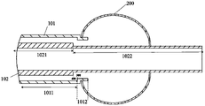
- Fig. 1 is the overall schematic diagram of the inflation state of the balloon catheter provided by a preferred embodiment of the present invention
- FIG. 2 is an overall schematic diagram of the contracted state of the balloon catheter provided by a preferred embodiment of the present invention
- FIG. 3 is a cross-sectional view of a distal end portion of a balloon catheter provided by a preferred embodiment of the present invention.
- FIG. 4 is a cross-sectional view of a distal end portion of a balloon catheter provided by a preferred embodiment of the present invention.
- FIG. 5 is a cross-sectional view of a distal end portion of a balloon catheter provided by a preferred embodiment of the present invention.
- FIG. 6 is a cross-sectional view of a distal end portion of a balloon catheter provided by a preferred embodiment of the present invention.
- FIG. 7 is a cross-sectional view of a distal end portion of a balloon catheter provided by a preferred embodiment of the present invention.
- FIG. 8 is an overall schematic diagram of a balloon catheter provided by a preferred embodiment of the present invention.
- FIG. 9 is a cross-sectional view of a distal end portion of a balloon catheter provided by a preferred embodiment of the present invention.
- FIG. 10 is a cross-sectional view of the distal end portion of a balloon catheter provided by a preferred embodiment of the present invention.
- 100 tubular element; 200: balloon; 101: outer tube; 102: inner tube; 1011: outer tube body; 1012: first recess; 1012-1: first transition zone; ; 1013: distal end of outer tube; 1013-1: second transition zone; 1013-2: second straight zone; 1014: liquid through hole; 1021: main body of inner tube; 1022: second recess; 1022-1: 3rd transition zone; 1022-2: third straight zone; 1023: distal end of inner tube; 1023-1: fourth transition zone; 1023-2: fourth straight zone; 300: first transition position; 400 : The second transition position.
- the core idea of the present invention is to provide a balloon catheter, which includes: a tubular element and a balloon; the tubular element includes an inner tube and an outer tube, the balloon is fixed to the tubular element, the balloon has an inflated state and a deflated state, and an outer tube sleeve It is arranged on the outside of the inner tube, and a first cavity is formed between the outer tube and the inner tube; the outer tube includes an outer tube main body and a first concave part, the first concave part is located at the distal end of the outer tube main body, and the outer diameter of the first concave part is smaller than the outer diameter of the outer tube.
- the outer diameter of the tube body, the inner diameter of the first recess is smaller than the inner diameter of the outer tube body, and the proximal end of the balloon is fixedly connected to the first recess;
- the inner tube includes an inner tube body and a second recess, and the second recess is located at the far end of the inner tube body. end, the outer diameter of the second recess is smaller than the outer diameter of the main body of the inner tube.
- FIGS. 1 and 2 are overall schematic diagrams of the balloon catheter provided by the first embodiment of the present invention
- FIG. 3 is a cross-sectional view of the distal end of the balloon catheter provided by the first embodiment of the present invention.
- the balloon catheter provided by the present invention includes a tubular element 100 and a balloon 200
- the tubular element 100 includes an outer tube 101 and an inner tube 102
- the balloon 200 is fixed to the tubular element 100
- the outer tube 101 is sleeved It is disposed outside the inner tube 102
- a first cavity is formed between the outer tube 101 and the inner tube 102
- the balloon 200 has an inflated state and a deflated state.
- FIG. 1 and FIG. 3 are the overall schematic diagram and the sectional view of the distal end when the balloon 200 is in the inflated state, respectively, and FIG. 2 is the overall schematic diagram of the balloon 200 in the deflated state. 200 is interchangeable between an expanded state and a contracted state.
- the outer tube 101 includes an outer tube body 1011 and a first recess 1012 , the first recess 1012 is located at the distal end of the outer tube body 1011 , the proximal end of the balloon 200 is fixed to the first recess 1012 , and the The distal end is fixed to the inner tube 102 .
- the balloon 200 is fixed between the outer tube 101 and the inner tube 102, which can reduce the influence of the presence of the balloon 200 on the overall outer diameter of the balloon catheter and the compliance performance of the balloon catheter.
- the inner tube 102 of the balloon catheter includes an inner tube main body 1021 and a second concave portion 1022 , the second concave portion 1022 is located at the distal end of the inner tube main body 1021 , and the outer diameter of the second concave portion 1022 is smaller than that of the inner tube main body 1021 .
- Outer diameter, the proximal end of the balloon 200 is fixed to the first recess 1012
- the distal end of the balloon 200 is fixed to the second recess 1022 .
- Recesses are provided on the outer tube 101 and the inner tube 102 of the balloon catheter, which can be used to accommodate at least part of the volume of the balloon 200, reduce the thickness of the connection position, and partially or completely eliminate the impact of the balloon on the hardness of the balloon catheter. , to ensure the flexibility of the balloon catheter, so that the balloon catheter can be smoothly pushed in the blood vessel, and the flexibility of the distal end of the balloon catheter is increased, further enhancing the delivery performance of the balloon catheter in the blood vessel.
- the concave portion is provided on the inner tube 102, which can ensure the volume of the liquid passage cavity, and prevent the problem of low balloon inflation and contraction rate due to the decrease of the liquid passage cavity.
- the outer diameter of the first concave portion 1012 is smaller than the outer diameter of the outer tube main body 1011
- the inner diameter of the first concave portion 1012 is smaller than the inner diameter of the outer tube main body 1011
- the proximal end of the balloon 200 is fixed to the outside of the first concave portion 1012 . surface.
- the axial length of the first recess 1012 is 2-20 mm; in this embodiment, the axial length of the first recess 1012 is 12 mm; in some other embodiments, the axial length of the first recess 1012 The length is 2mm; in other embodiments, the axial length of the first recess 1012 is 5mm; in other embodiments, the axial length of the first recess 1012 is 10mm; in other embodiments, the first recess 1012 has an axial length of 10mm.
- the axial length of 1012 is 15 mm; in some other embodiments, the axial length of first recess 1012 is 20 mm.
- the axial length of the second recess 1022 is 2-60 mm; in this embodiment, the axial length of the second recess 1022 is 30 mm; in some other embodiments, the axial length of the second recess 1022 The length is 2mm; in some other embodiments, the axial length of the second recess 1022 is 10mm; in some other embodiments, the axial length of the second recess 1022 is 25mm; in some other embodiments, the second recess 1022 has an axial length of 25mm.
- the axial length of the 1022 is 45 mm; in some other embodiments, the axial length of the second recess 1022 is 60 mm.
- the first concave portion 1012 sequentially includes a first transition area 1012-1 and a first straight area 1012-2 from the proximal end to the distal end, and the inner diameter of the first transition area 1012-1 is From the inner diameter of the outer tube main body 1011 to the inner diameter of the first flat region 1012-2, the outer diameter of the first transition region 1012-1 transitions from the outer diameter of the outer tube main body 1011 to the outer diameter of the first flat region 1012-2
- the first transition area 1012-1 is a variable diameter area, and at the first transition area 1012-1, both the inner diameter and the outer diameter of the outer tube 101 become smaller.
- the second concave portion 1022 sequentially includes a third transition region 1022-1 and a third straight region 1022-2 from the proximal end to the distal end, and the outer diameter of the third transition region 1022-1 extends from the inner tube body 1021
- the outer diameter of 1022-2 transitions to the outer diameter of the third straight area 1022-2, the third transition area 1022-1 is a variable diameter area, and at the third transition area 1022-1, the outer diameter of the inner tube 102 becomes smaller.
- the inner surface and the outer surface of the first transition zone 1012-1 are inclined surfaces at a certain angle with the axial direction of the outer tube main body 1011 (or with the tubular element 100). The same, both are 45°.
- the inner surface and the outer surface of the first transition zone 1012-1 are inclined surfaces with a certain angle to the axial direction of the outer tube main body 1011 (or the tubular element 100), and the inclination angle is the same, and both are greater than Any angle between 0 and 90°; in other embodiments, the inner and outer surfaces of the first transition zone 1012-1 are at a certain angle with the outer tube body 1011 (or with the tubular element 100) axially In some other embodiments, the inner and outer surfaces of the first transition zone 1012-1 are axially aligned with the outer tube main body 1011 (or with the tubular element 100).
- a certain angle of the inclined surface, the inclination angle is the same, both are 5°; in some other embodiments, the inner surface and the outer surface of the first transition zone 1012-11 are the axis with the outer tube main body 1011 (or with the tubular element 100) In some other embodiments, the inner surface and the outer surface of the first transition zone 1012-1 are the same as the outer tube main body 1011 (or the same as the tubular element). 100) Axial vertical plane. In all embodiments, the axial length of the first transition zone 1012-1 is 0-10 mm; in this embodiment, the axial length of the first transition zone 1012-1 is 4 mm; in some other embodiments, the first transition zone 1012-1 has an axial length of 4 mm.
- the axial length of a transition zone 1012-1 is 0 mm; in other embodiments, the axial length of the first transition zone 1012-1 is 3 mm; in other embodiments, the axis of the first transition zone 1012-1 The axial length is 5 mm; in other embodiments, the axial length of the first transition zone 1012-1 is 8 mm; in other embodiments, the axial length of the first transition zone 1012-1 is 10 mm.
- the outer surface of the third transition area 1022-1 is an inclined surface at a certain angle to the axial direction of the inner tube main body 1021 (or the tubular element 100).
- the angle is 10°; in other embodiments, the outer surface of the third transition zone 1022-1 is an inclined surface that forms a certain angle with the axial direction of the inner tube body 1021 (or the tubular element 100), and the angle of the inclined surface is 5 °; in some other embodiments, the outer surface of the third transition zone 1022-1 is an inclined surface that forms a certain angle with the axial direction of the inner tube main body 1021 (or the tubular element 100), and the angle of the inclined surface is 15°; In some other embodiments, the outer surface of the third transition zone 1022-1 is an inclined surface that forms a certain angle with the axial direction of the inner tube main body 1021 (or the tubular element 100), and the angle of the inclined surface is 25°; in other implementations In an example, the outer surface of the third transition
- the inner surface of the third transition zone 1022-1 is axially parallel to the inner tube body 1021 (or to the tubular element 100), and the outer surface of the third transition zone 1022-1 is axially parallel to the inner tube body 1021 (or to the tubular element 100).
- An inclined surface that forms a certain angle with the axial direction of the tubular element 100), and the inclined angle can be any angle in the range of 0-90°, such as 5°, 15°, 30°, 40°, 45°, 60°, 75°, 85°; in some other embodiments, the inner surface of the third transition zone 1022-1 is axially parallel to the inner tube body 1021 (or to the tubular element 100), and the outer surface of the third transition zone 1022-1 is parallel to the inner tube The face of the body 1021 (or to the tubular element 100 ) axially perpendicular; in some other embodiments, the inner surface of the third transition zone 1022-1 is angled to the axial direction of the inner tube body 1021 (or to the tubular element 100 ).
- the angle of inclination can be any angle from 0° to 90°, such as 5°, 15°, 30°, 40°, 45°, 60°, 75°, 85°; in some other embodiments, the first
- the inner surface of the third transition zone 1022-1 is the plane that is axially perpendicular to the inner tube body 1021 (or to the tubular element 100).
- the axial length of the third transition zone 1022-1 is 0-10 mm; in this embodiment, the axial length of the third transition zone 1022-1 is 5 mm; in other embodiments, the third transition zone 1022-1 has an axial length of 5 mm; The axial length of the third transition zone 1022-1 is 0 mm; in some other embodiments, the axial length of the third transition zone 1022-1 is 3 mm; in some other embodiments, the axis of the third transition zone 1022-1 The axial length is 5 mm; in some other embodiments, the axial length of the third transition zone 1022-1 is 8 mm; in other embodiments, the axial length of the third transition zone 1022-1 is 10 mm.
- the outer diameter of the outer tube body 1011 is 1.0mm-3.7mm, the outer diameter of the first flat region 1012-2 is 0.7m-3.5mm, and the outer diameter of the first flat region 1012-2 is the same as
- the outer diameter ratio of the outer tube main body 1011 is 0.7-1.0; in this embodiment, the outer diameter of the outer tube main body 1011 is 2.8 mm, the outer diameter of the first flat area 1012-2 is 2.6 mm, and the first flat area is 2.6 mm.
- the ratio of the outer diameter of 1012-2 to the outer diameter of the outer tube body 1011 is 0.928; in some other embodiments, the outer diameter of the outer tube body 1011 is 3.7mm, and the outer diameter of the first flat region 1012-2 is 2.8mm , the ratio of the outer diameter of the first flat region 1012-2 to the outer diameter of the outer tube main body 1011 is 0.757; in some other embodiments, the outer diameter of the outer tube main body 1011 is 3.5 mm, and the outer diameter of the first flat region is 0.757.
- the ratio of the outer diameter of the first flat area 1012-2 to the outer diameter of the outer tube main body 1011 is 1.0; in some other embodiments, the outer diameter of the outer tube main body 1011 is 1.0 mm, and the first flat area The outer diameter of 1012-2 is 0.7 mm, and the ratio of the outer diameter of the first flat region 1012-2 to the outer diameter of the outer tube main body 1011 is 0.7.
- the outer diameter of the inner tube body 1021 is 0.5mm-3.2mm
- the outer diameter of the third flat region 1022-2 is 0.3m-3.2mm
- the outer diameter of the third flat region 1022-2 is the same as
- the outer diameter ratio of the outer tube main body 1011 is 0.6-1.0; in this embodiment, the outer diameter of the inner tube main body 1021 is 2.8 mm, the outer diameter of the third flat area 1022-2 is 2.4 mm, and the third flat area is 2.4 mm.
- the ratio of the outer diameter of the 1022-2 to the outer diameter of the outer tube body 1011 is 0.857; in some other embodiments, the outer diameter of the inner tube body 1021 is 3.2mm, and the outer diameter of the third flat region 1022-2 is 3.2mm , the ratio of the outer diameter of the third straight area 1022-2 to the outer diameter of the inner tube main body 1021 is 1.0; in some other embodiments, the outer diameter of the inner tube main body 1021 is 0.5 mm, and the third flat area 1022-2 The outer diameter of the inner tube body 1021 is 0.3 mm, and the ratio of the outer diameter of the third straight area 1022-2 to the outer diameter of the inner tube body 1021 is 0.6; in some other embodiments, the outer diameter of the inner tube body 1021 is 1.0 mm, and the third The outer diameter of the flat area 1022-2 is 0.8 mm, and the ratio of the outer diameter of the third flat area 1022-2 to the outer diameter of the inner tube main body 1021 is 0.8; in some other embodiments, the outer diameter
- the most distal end of the outer tube main body 1011 of the balloon catheter provided in the first embodiment has a first transition position 300 .
- the first transition position 300 is the position where the outer diameter and inner diameter of the outer tube 101 of the balloon catheter begin to change;
- the position at which the outer diameter and/or the inner diameter begins to change ie, the boundary position between the outer tube main body and the first concave portion is the first transition position.
- the most distal end of the inner tube body 1021 of the balloon catheter has a second transition position 400.
- the second transition position 400 is the position where the outer diameter of the inner tube of the balloon catheter begins to change; in other implementations, the second transition position 400 may also be the position where the outer diameter and inner diameter of the inner tube 102 of the balloon catheter begin to change (ie, the boundary position between the inner tube main body and the second concave portion is the second transition position).
- the first transition position 300 may be a plane with the same cross-sectional shape as the most distal position of the outer tube body 1011
- the second transition position 400 may be the cross section of the most distal position of the inner tube body 1021
- the surfaces with the same shape are collectively referred to as the first transition position 300 and the second transition position 400 for the convenience of description herein.
- the projection of the first transition position 300 in the axial direction of the tubular element 100 is located distal to the projection of the second transition position 400 in the axial direction of the tubular element 100; and in this embodiment, the third The outer surface of the transition zone 1022-1 forms a first inclination angle with the axial direction of the tubular element 100, the inner surface of the first transition zone 1012-1 forms a second inclination angle with the axial direction of the tubular element 100, The first inclination angle is greater than or equal to the second inclination angle.
- the inner diameter of the outer tube 101 of the balloon catheter begins to decrease at the first transition position 300, and the outer diameter of the inner tube 102 of the balloon catheter begins to decrease at the second transition position 400.
- the projection of the position 300 in the axial direction of the tubular element 100 is located at the distal end of the projection of the second transition position 400 in the axial direction of the tubular element 100 , and the inclination of the third transition zone 1022 - 1 with the axial direction of the tubular element 100 is provided
- the angle is larger than the inclination angle between the first transition zone 1012-1 and the axial direction of the tubular element 100, which can ensure that the volume of the first cavity will not become too small due to the reduction of the inner diameter of the outer tube 101.
- the overall length of the balloon catheter is 80-160 cm; in this embodiment, the overall length of the balloon catheter is 130 cm; in some other embodiments, the overall length of the balloon catheter is 80 cm; in other In some embodiments, the overall length of the balloon catheter is 160 cm; in other embodiments, the overall length of the balloon catheter is 115 cm; in other embodiments, the overall length of the balloon catheter is 110 cm; in other embodiments In an example, the overall length of the balloon catheter is 140 cm; in some other embodiments, the overall length of the balloon catheter is 150 cm.
- the balloon 200 is a polymer membrane
- the first cavity is used for passing or withdrawing liquid, so as to control the transition between the inflation state and the shrinking state of the balloon 200
- the first cavity is used for passing or returning the liquid.
- the pumped liquid such as contrast fluid, physiological saline, etc.
- the first cavity when the first cavity is in a liquid-filled state, the balloon 200 is in an expanded state; when the first cavity is in a vacuum state, the balloon 200 is in a contracted state.
- the thickness of the polymer film is 0.10mm; in other embodiments, the thickness of the polymer film is 0.05mm-0.15mm, such as 0.05mm, 0.08mm, 0.12mm, 0.15mm.
- the material of the polymer film is silica gel; in some other embodiments, the material of the polymer film is polyurethane; in some other embodiments, the material of the polymer film is latex; in some other embodiments , the material of the polymer film is polyethylene; in some other embodiments, the material of the polymer film is polytetrafluoroethylene; in some other embodiments, the material of the polymer film is expanded polytetrafluoroethylene; in other In some embodiments, the material of the polymer film is a mixture of polyurethane and polyethylene, and the material ratio is 2:1; in other embodiments, the material of the polymer film is polytetrafluoroethylene and expanded polytetrafluoroethylene The material ratio is 1:1; in some other embodiments, the material of the polymer film is a mixture of silica gel, polyurethane and polyethylene, and the material ratio is 1:1:1.
- the proximal end of the balloon 200 is connected to the first flat region 1012-2, and the connection may be adhesive, bound or fusion connection; in other embodiments, the proximal end of the balloon 200 may be connected to the first flat region 1012-2.
- the first transition region 1012-1 is connected, and the connection method can be bonding, binding or fusion connection.
- the inner tube 102 has a three-layer structure, which is a first polymer layer, a reinforcing layer, and a second polymer layer in sequence from the inside to the outside.
- the material of the first polymer layer is polytetrafluoroethylene
- the reinforcing layer is Wire braided structure
- the material of the reinforcing layer is stainless steel
- the second polymer layer is made of polyether block polyamide, nylon, polyurethane, polyethylene, polyolefin elastomers spliced in the axial direction
- the outer tube 101 is a single-height Molecular layer
- the material of the outer tube 101 is polyether block polyamide.
- both the inner tube 102 and the outer tube 101 have a three-layer structure, which are a first polymer layer, a reinforcing layer, and a second polymer layer in sequence from the inside to the outside; in other embodiments, the inner tube 102 is a single-layer polymer structure, and the outer tube 101 is a three-layer structure; in other embodiments, the inner tube 102 is a three-layer structure, and the outer tube 101 is a double-layer polymer structure.
- the reinforcement layer of the inner tube 102 and/or the outer tube 101 is a wire spiral wound structure; in some other embodiments, the reinforcement layer of the inner tube 102 and/or the outer tube 101 is a cut tube; in some other embodiments, the reinforcement layer of the inner tube 102 and/or the outer tube 101 is a combination of a wire braided structure and a wire helical structure; in some other embodiments, the reinforcement layer of the inner tube 102 and/or the outer tube 101 It is a combination of a wire braided structure and a cut tube; in some other embodiments, the reinforcement layer of the inner tube 102 and/or the outer tube 101 is a combination of a cut tube and a wire helix.
- the material of the reinforcement layer of the inner tube 102 and/or the outer tube 101 includes Nitinol; in other embodiments, the material of the reinforcement layer of the inner tube 102 and/or the outer tube 101 includes cobalt chromium alloy; in some other embodiments, the material of the reinforcement layer of the inner tube 102 and/or the outer tube 101 includes polymer; in some other embodiments, the material of the reinforcement layer of the inner tube 102 and/or the outer tube 101 is nickel A combination of titanium alloy and stainless steel; in some other embodiments, the material of the reinforcement layer of the inner tube 102 and/or the outer tube 101 is a combination of nickel-titanium alloy and polymer.
- the balloon catheter includes a first imaging ring, and the first imaging ring is located at the head of the balloon catheter; the balloon catheter further includes a second imaging ring, and the second imaging ring is located on the inner tube 102 and the balloon 200 location suitable for the location.
- a second cavity is formed inside the inner tube 102 of the balloon catheter, and the entire inner diameter of the second cavity is the same.
- the inner diameter of the second cavity is 0.1mm-3.0mm, and the outer diameter of the outer tube body 1011 is 0.5mm-3.7mm; in this embodiment, the inner diameter of the second cavity is 2.3mm, the outer The outer diameter of the tube body 1011 is 2.8 mm, and the ratio of the inner diameter of the second cavity to the outer diameter of the outer tube body 1011 is 0.821; in some other embodiments, the inner diameter of the second cavity is 0.1 mm, and the outer tube The outer diameter of the main body 1011 is 0.5 mm, and the ratio of the inner diameter of the second cavity to the outer diameter of the outer tube body 1011 is 0.2; in some other embodiments, the inner diameter of the second cavity is 3.0 mm, and the outer tube body is 3.0 mm.
- the outer diameter of the 1011 is 3.6 mm, and the ratio of the inner diameter of the second cavity to the outer diameter of the outer tube body 1011 is 0.833; in some other embodiments, the inner diameter of the second cavity is 2.7 mm, and the outer tube body 1011
- the outer diameter of the second cavity is 3.0mm, and the ratio of the inner diameter of the second cavity to the outer diameter of the outer tube body 1011 is 0.9; in some other embodiments, the inner diameter of the second cavity is 2.5mm, and the outer diameter of the outer tube body 1011
- the outer diameter is 3.7 mm, and the ratio of the inner diameter of the second cavity to the outer diameter of the outer tube main body 1011 is 0.676.
- the second cavity is used to pass the medical device.
- the length of the balloon 200 when deflated is 10 mm; in other embodiments, the length of the balloon 200 when deflated is 5-30 mm; in another embodiment, the length of the balloon 200 when deflated The length is 5mm; in another embodiment, the length of the balloon 200 when deflated is 8mm; in another embodiment, the length of the balloon 200 when deflated is 15mm; in another embodiment, the length of the balloon 200 The length when deflated is 20 mm; in another embodiment, the length of the balloon 200 when deflated is 24 mm; in another embodiment, the length of the balloon 200 when deflated is 30 mm.
- an angle transition is formed between the outer tube main body 1011 and the first concave portion 1012, and between the first transition area 1012-1 and the first straight area 1012-2;
- a smooth transition may be formed between the pipe main body 1011 and the first concave portion 1012, and/or between the first transition area 1012-1 and the first straight area 1012-2.
- the first flat area 1012-2 is a flat area with a smooth surface; in other embodiments, the first flat area 1012-2 may be a surface with a concave-convex structure, a groove structure or a curved structure , but the overall inner and outer diameter of the same tubular structure.
- an angle transition is formed between the inner tube main body 1021 and the second recess 1022, and between the third transition area 1022-1 and the third straight area 1022-2; in other embodiments, the inner Between the pipe body 1021 and the second concave portion 1022, and/or between the third transition area 1022-1 and the third straight area 1022-2, there may be a smooth transition in an arc.
- the third flat region 1022-2 is a flat region with a smooth surface; in other embodiments, the third flat region 1022-2 can be a surface with concave-convex structure, groove structure or curved structure , but the overall inner and outer diameter of the same tubular structure.
- FIG. 4 is a cross-sectional view of the distal end portion of the balloon catheter provided in the second embodiment.
- the balloon 200 of the balloon catheter shown in FIG. 4 is in an expanded state.
- the overall structure of the balloon catheter provided in the second embodiment is similar to that of the first embodiment, which will not be repeated here.
- the inner tube 102 of the balloon catheter provided in the second embodiment includes: The inner tube body 1021, the second recess 1022, the inner tube distal end 1023, the second recess 1022 is located at the distal end of the inner tube body 1021, and the outer diameter of the second recess 1022 is smaller than the outer diameter of the inner tube body 1021, The proximal end of the balloon 200 is fixed to the first recess 1012 , and the distal end of the balloon 200 is fixed to the second recess 1022 .
- the distal end portion 1023 of the inner tube is located at the distal end of the second concave portion 1022, the outer diameter of the distal end portion 1023 of the inner tube is smaller than the outer diameter of the second concave portion 1022, and the distal end portion 1023 of the inner tube is located at the head end of the balloon catheter.
- the presence of the distal end portion 1023 of the inner tube gradually increases the compliance performance of the balloon catheter from the proximal end to the distal end, ensuring the delivery and positioning capability of the balloon catheter.
- the distal end portion 1023 of the inner tube includes a fourth transition area 1023-1 and a fourth straight area 1023-2 in sequence from the proximal end to the distal end, and the outer diameter of the fourth transition area 1023-1 increases from the third
- the outer diameter of the straight area 1022-2 transitions to the outer diameter of the fourth straight area
- the fourth transition area 1023-1 is a variable diameter area
- the outer diameter of the inner tube 102 becomes smaller .
- the outer diameter of the fourth flat area 1023-2 is 0.2mm-3.1mm; in this embodiment, the outer diameter of the fourth flat area 1023-2 is 2.0mm; in other embodiments In some embodiments, the outer diameter of the fourth straight area 1023-2 is 0.2 mm; in other embodiments, the outer diameter of the fourth straight area 1023-2 is 1.5 mm; in some other embodiments, the fourth straight area The outer diameter of the zone 1023-2 is 3.1 mm.
- the outer diameter of the fourth flat area 1023-2 is smaller than the outer diameter of the second recess 1022, and the inner diameter of the fourth flat area 1023-2 is equal to the inner diameter of the second recess 1022; in other embodiments , the outer diameter of the fourth straight area 1023 - 2 is smaller than the outer diameter of the second concave portion 1022 , and the inner diameter of the fourth straight area 1023 - 2 is larger than the inner diameter of the second concave portion 1022 .
- a fourth flat area 1023-2 at the distal end of the inner tube 102 With a smaller outer diameter than the proximal end, the hardness of the distal end of the balloon catheter can be further reduced, and the passing ability of the balloon catheter in the blood vessel can be enhanced , reduce the risk of puncturing the blood vessel at the distal end of the balloon catheter, and improve the performance in place.
- the distal end portion 1023 of the inner tube may include 2-10 transition regions and straight regions, and the transition regions and the straight regions are arranged at intervals in sequence, so that the outer diameter of the distal end portion 1023 of the inner tube gradually decreases, and the inner tube The outer diameter of the distal end portion 1023 may gradually decrease from 3 mm at the proximal end to 0.6 mm at the distal end.
- the distal end portion 1023 of the inner tube includes five transition regions and straight regions that are spaced in sequence, and the outer diameter of the distal end portion 1023 of the inner tube is reduced from 2.7 mm at the proximal end to 0.9 mm at the distal end; In some other embodiments, the distal end portion 1023 of the inner tube includes 10 transition regions and straight regions spaced in sequence, and the outer diameter of the distal end portion 1023 of the inner tube is reduced from 3.0 mm at the proximal end to 0.6 mm at the distal end; In other embodiments, the distal end portion 1023 of the inner tube includes two transition regions and a straight region spaced in sequence, and the outer diameter of the distal end portion 1023 of the inner tube decreases from 2.4 mm at the proximal end to 1.65 mm at the distal end.
- the inner tube distal end 1023 is a tapered tubular structure with a gradually decreasing outer diameter, and the outer diameter of the inner tube distal end 1023 is tapered; in some embodiments, the inner tube distal end 1023 The outer diameter of the inner tube tapers from 3 mm at the proximal end to 0.6 mm at the distal end; in some embodiments, the outer diameter of the inner tube distal portion 1023 is tapered from 2.5 mm at the proximal end to 0.6 mm at the distal end; in some implementations For example, the outer diameter of the inner tube distal end 1023 tapers from 2 mm at the proximal end to 0.9 mm at the distal end.
- the projection of the first transition position 300 in the axial direction of the tubular element 100 is located at the second transition position 400 in the axial direction of the tubular element 100 (axial direction of the tubular element 100 ) on the far end of the projection.
- the distance between the projection of the second transition location 400 in the axial direction of the tubular element 100 and the projection of the first transition location 300 in the axial direction of the tubular element 100 is 10mm-80mm.
- the distance between the projection of the second transition position 400 in the axial direction of the tubular element 100 and the projection of the first transition position 300 in the axial direction of the tubular element 100 is 20 mm; in other embodiments , the distance between the projection of the second transition position 400 in the axial direction of the tubular element 100 and the projection of the first transition position 300 in the axial direction of the tubular element 100 is 10 mm; in some other embodiments, the second transition position 400 The distance between the projection in the axial direction of the tubular element 100 and the projection of the first transition location 300 in the axial direction of the tubular element 100 is 30 mm; in some other embodiments, the second transition location 400 is in the axis of the tubular element 100 The distance between the upward projection and the projection of the first transition position 300 in the axial direction of the tubular element 100 is 40 mm; in some other embodiments, the projection of the second transition position 400 in the axial direction of the tubular element 100 and the first The distance between the projection of a transition position 300 in the axial direction of the tubular
- the first transition position 300 is located at the distal end of the second transition position 400 , which can ensure that the volume of the liquid passage cavity will not become too small due to the reduction of the inner diameter of the outer tube 101 , thereby ensuring the efficiency of liquid passing or withdrawing.
- the axial distance between the first transition position 300 and the second transition position 400 is in an appropriate range, which ensures the volume of the liquid passage cavity, and at the same time ensures the support performance of the proximal end and the soft performance of the distal end of the balloon catheter , so that the ability of the balloon catheter to bend and be in place is good.
- the inner tube 102 has a three-layer structure, and the inside and outside are sequentially a first polymer layer, a reinforcing layer, and a second polymer layer.
- the outer tube 101 has a double-layer structure, the outer layer of the outer tube 101 is a polymer layer, the inner layer of the outer tube 101 is a reinforcement layer, and the reinforcement layer of the outer tube 101 is a cut pipe material.
- the balloon catheter includes a second imaging ring, and the second imaging ring is provided at the position of the inner tube 102 corresponding to the position of the balloon 200 .
- the fourth flat region 1023-2 is a flat region with a smooth surface; in other embodiments, the fourth flat region 1023-2 may be a surface with a concave-convex structure, a groove structure or a curved structure , but the overall inner and outer diameter of the same tubular structure.
- the third embodiment provides a balloon catheter.
- FIG. 5 is a cross-sectional view of the distal end portion of the balloon catheter provided in the third embodiment.
- the balloon 200 of the balloon catheter shown in FIG. 5 is in an inflated state.
- the overall structure of the balloon catheter provided in the third embodiment is similar to that of the first embodiment, which will not be repeated here.
- the difference from the first embodiment is that in the balloon catheter provided in the third embodiment, the first concave portion
- the first transition region 1012-1 of 1012 is a variable diameter region perpendicular to the axial direction of the tubular element 100, that is, the outer surface and the inner surface of the first transition region 1012-1 are at 90° to the axial direction of the tubular element 100.
- the axial length of the transition zone 1012-1 that is, the thickness of the pipe here, is 0.1 mm
- the axial length of the first concave portion 1012 is 5 mm.
- the projection of the first transition location 300 in the axial direction of the tubular element 100 is located distal to the projection of the second transition location 400 in the axial direction of the tubular element 100 .
- the inner tube 102 has a three-layer structure, and the inside and outside are sequentially a first polymer layer, a reinforcing layer, and a second polymer layer.
- the outer tube 101 has a double-layer structure, the outer layer of the outer tube 101 is a polymer layer, the inner layer of the outer tube 101 is a reinforcement layer, and the reinforcement layer of the outer tube 101 is a cut pipe material.
- the balloon catheter includes a first imaging ring, and the first imaging ring is located at the head end of the balloon catheter; the balloon catheter further includes a second imaging ring and a third imaging ring, the second imaging ring and the third imaging ring
- the ring is disposed on the inner tube 102 opposite to the position of the balloon 200 , the second imaging ring is located at the distal position of the balloon 200 , and the third imaging ring is located at the proximal position of the balloon 200 .
- FIG. 6 is a cross-sectional view of the distal end of the balloon catheter provided in the fourth embodiment.
- the balloon 200 of the balloon catheter shown in FIG. 6 is in an inflated state.
- the overall structure of the balloon catheter provided in the fourth embodiment is similar to that of the third embodiment, which will not be repeated here.
- the difference from the third embodiment is that in the balloon catheter provided in the fourth embodiment, the second concave portion
- the third transition region 1022-1 of 1012 is a variable diameter region perpendicular to the axial direction of the tubular element 100, that is, the outer surface and the inner surface of the third transition region 1022-1 are at 90° to the axial direction of the tubular element 100, and the first The axial length of the transition region 1013-1 is 0.5 mm, and the axial length of the first recess 1012 is 8 mm.
- the first transition area 1012-1 of the first recess 1012 is a variable diameter area perpendicular to the axial direction of the tubular element 100, that is, the outer surface of the first transition area 1012-1 is 90° from the axial direction of the tubular element 100, and the third transition area
- the axial length of the region 1022-1 is 0 mm
- the axial length of the second recess 1022 is 20 mm.
- the inner diameter of the second concave portion 1022 is the same as the inner diameter of the inner tube body 1021
- the thickness of the distal end of the inner tube 102 is smaller than the thickness of the inner tube body 1021 .
- the outer diameter of the second recess 1022 is smaller than the outer diameter of the inner tube body 1021 , the inner diameter of the second recess 1022 is larger than the inner diameter of the inner tube body 1021 , and the thickness of the distal end of the inner tube is smaller than the thickness of the inner tube body 1021 In some other embodiments, the outer diameter of the second recess 1022 is smaller than the outer diameter of the inner tube body 1021 , and the inner diameter of the second recess 1022 is smaller than the inner diameter of the inner tube body 1021 .
- the projection of the first transition location 300 in the axial direction of the tubular element 100 is located distal to the projection of the second transition location 400 in the axial direction of the tubular element 100 .
- the distance between the projection of the second transition location 400 in the axial direction of the tubular element 100 and the projection of the first transition location 300 in the axial direction of the tubular element 100 is 10mm-80mm.
- the distance between the projection of the second transition position 400 in the axial direction of the tubular element 100 and the projection of the first transition position 300 in the axial direction of the tubular element 100 is 25 mm; in some other embodiments , the distance between the projection of the second transition position 400 in the axial direction of the tubular element 100 and the projection of the first transition position 300 in the axial direction of the tubular element 100 is 15 mm; in some other embodiments, the second transition position 400 The distance between the projection in the axial direction of the tubular element 100 and the projection of the first transition location 300 in the axial direction of the tubular element 100 is 45 mm; in some other embodiments, the second transition location 400 is in the axis of the tubular element 100 The distance between the upward projection and the projection of the first transition position 300 in the axial direction of the tubular element 100 is 65 mm; in some other embodiments, the projection of the second transition position 400 in the axial direction of the tubular element 100 and the first The distance between the projections of a transition position 300 in the axial
- the inner tube 102 has a double-layer structure, and the inside and outside are the first polymer layer and the second polymer layer in sequence.
- the outer tube 101 has a single-layer polymer structure.
- the balloon catheter includes a second imaging ring and a third imaging ring, the second imaging ring and the third imaging ring are sleeved on the inner tube 102 adapted to the position of the balloon 200 , and the second imaging ring is located at At the distal position of the balloon 200 , the third imaging ring is located at the proximal position of the balloon 200 .
- the third transition area 1022-1 is a variable diameter area perpendicular to the axial direction of the tubular element 100, that is, outside the third transition area 1022-1 Both the surface and the inner surface are at 90° axially to the tubular element 100, the axial length of the third transition zone 1022-1 is 0.05 mm, and the axial length of the second recess 1022 is 8 mm.
- the inner surface and the outer surface of the first transition area 1012-1 are inclined surfaces which form a certain angle with the axial direction of the tubular element 100, and the inclination angle is the same, and both are 40°.
- FIG. 8 is an overall schematic diagram of the balloon catheter provided by the fifth embodiment of the present invention
- FIG. 9 is a cross-sectional view of the distal end of the balloon catheter provided by the fifth embodiment of the present invention.
- the balloon catheter provided by the present invention includes a tubular element 100 and a balloon 200
- the tubular element 100 includes an outer tube 101 and an inner tube 102
- the balloon 200 is fixed to the outer tube 101 in the tubular element 100 .
- the outer tube 101 is sleeved on the outside of the inner tube 102
- a first cavity is formed between the outer tube 101 and the inner tube 102 .
- the balloon 200 has an inflated state and a deflated state, and the balloon 200 can be switched between the inflated state and the deflated state.
- the outer tube 101 includes an outer tube main body 1011 and a first concave portion 1012 , the first concave portion 1012 is located at the distal end of the outer tube main body 1011 , the balloon 200 is fixed to the first concave portion 1012 , and the first concave portion 1012 is provided with a
- the liquid through hole 1014, the first cavity is used to pass or withdraw the liquid to control the expansion and contraction of the balloon 200; when the first cavity is in a liquid-filled state, the balloon 200 is in an expanded state; the first cavity is in a vacuum state , the balloon 200 is in a deflated state.
- the liquid through hole 1014 is used for passing liquid, and the liquid in the first cavity enters the balloon 200 through the liquid through hole 1014 to inflate the balloon 200 or withdraw from the balloon 200 to deflate the balloon 200 .
- the first concave portion 1012 has been described in detail, and will not be repeated here.
- the outer tube 101 further includes a distal end portion 1013 of the outer tube, which is located at the distal end of the first recess 1012
- the diameter is larger than the outer diameter of the distal end of the first concave portion 1012, and the distal end of the distal end portion of the outer tube 1013 is fixedly connected to the inner tube 102;
- the second flat area 1013-2, the inner diameter of the second flat area 1013-2 is larger than the inner diameter of the first flat area 1012-2, and the outer diameter of the second flat area 1013-2 is larger than the first flat area 1012- 2,
- the inner and outer diameters of the second transition region 1013-1 gradually transition from the inner and outer diameters of the first flat region 1012-2 to the inner diameter of the second flat region 1013-2 from the proximal end to the distal end and outer diameter
- the second transition region 1013-1 is a diameter reduction region where both the inner diameter and the outer diameter of the outer tube 101 become larger.
- the inner diameter of the second flat region 1013-2 is equal to the inner diameter of the first flat region 1012-2, and the outer diameter of the second flat region 1013-2 is greater than that of the first flat region 1012-2 Outer diameter, the outer diameter of the second transition region 1013-1 gradually transitions from the outer diameter of the first flat region 1012-2 to the outer diameter of the second flat region 1013-2 from the proximal end to the distal end, the second transition region The inner diameter of 1013-1 remains unchanged, and the second transition zone 1013-1 is a diameter-reducing zone, where the outer diameter of the outer tube 101 increases.
- the distal end portion 1013 of the outer tube and the first concave portion can be combined to form a V-shaped, frame-shaped, arc-shaped, polygonal, irregular-shaped, etc.-shaped depression on the outer tube 101 .
- both the proximal end and the distal end of the balloon 200 are connected to the first flat region 1012-2, and the connection can be adhesive, bound or fusion connection; in other embodiments, the The proximal end can be connected to the first transition region 1012-1, and/or the distal end of the balloon 200 can be connected to the second transition region 1013-1, which can be bonded, bound or welded.
- the inner surface and the outer surface of the second transition zone 1013-1 are inclined surfaces which form a certain angle with the axial direction of the tubular element 100, and the inclination angle is the same, and both are 60°.
- the inner surface and the outer surface of the second transition zone 1013-1 are inclined surfaces that form a certain angle with the axial direction of the tubular element 100, and the inclination angle may be the same or different, and the inclination angle may be 0-90° Any angle, such as 5°, 15°, 30°, 40°, 45°, 60°, 75°, 85°; in some other embodiments, the inner surface and outer surface of the second transition zone 1013-1
- the surfaces are all planes perpendicular to the axial direction of the tubular element 100; in other embodiments, the inner surface of the second transition zone 1013-1 is axially parallel to the tubular element 100, and the outer surface of the second transition zone 1013-1 is parallel to the axial direction of the tubular element 100.
- the axial direction of the tubular element 100 is an inclined surface at a certain angle, and the inclined angle can be any angle between 0° and 90°, for example, 5°, 15°, 30°, 40°, 45°, 60°, 75°, 85° °; in some other embodiments, the inner surface of the second transition region 1013-1 is axially parallel to the tubular element 100, and the outer surface of the second transition region 1013-1 is a plane perpendicular to the axial direction of the tubular element 100; in all In the embodiment, the axial length of the second transition zone 1013-1 is 0-10 mm; in this embodiment, the axial length of the second transition zone 1013-1 is 5 mm; in other embodiments, the second transition zone 1013-1 has an axial length of 5 mm.
- the axial length of the zone 1013-1 is 0 mm; in some other embodiments, the axial length of the second transition zone 1013-1 is 3 mm; in some other embodiments, the axial length of the second transition zone 1013-1 is 8 mm; in some other embodiments, the axial length of the second transition region 1013-1 is 10 mm.
- the axial length of the outer tube distal end 1013 is 1-15 mm; in this embodiment, the axial length of the outer tube distal end 1013 is 10 mm; in some other embodiments, the outer tube distal The axial length of the end portion 1013 is 1 mm; in other embodiments, the axial length of the distal end portion 1013 of the outer tube is 8 mm; in other embodiments, the axial length of the distal end portion 1013 of the outer tube is 12 mm; In some other embodiments, the axial length of the outer tube distal portion 1013 is 15 mm.
- the outer diameter of the second flat region 1013-2 is 1.0-3.7 mm, and in this embodiment, the outer diameter of the second flat region 1013-2 is 2.8 mm. In some other embodiments, the outer diameter of the second flat area 1013-2 is 1.0 mm; in some other embodiments, the outer diameter of the second flat area 1013-2 is 2.0 mm; in some other embodiments , the outer diameter of the second straight area 1013-2 is 3.0 mm; in some other embodiments, the outer diameter of the second straight area 1013-2 is 3.7 mm;
- the distal end portion 1013 of the outer tube is connected to the inner tube 102 (not shown in FIG. 9 ), so that the distal end of the first cavity is closed, so that the liquid passing through the first cavity will not be far from the balloon catheter. end leak, thereby controlling inflation and deflation of the balloon 200. Therefore, the distal end of the distal end portion of the outer tube 1013 has a reduced diameter area (not shown in the figure), and the reduced diameter area gradually decreases in outer diameter from the proximal end to the distal end so that it can be connected to the inner tube 102 .
- the position where the distal end portion 1013 of the outer tube is connected to the inner tube 102 may be the most distal position of the inner tube 102 , or may be a position in the inner tube 102 .
- the inner tube 102 of the balloon catheter provided in this embodiment includes an inner tube body 1021 and a second recess 1022 from the proximal end to the distal end, and the second recess 1022 is located at the distal end of the inner tube body 1021,
- the outer diameter of the second recess 1022 is smaller than the outer diameter of the inner tube body 1021 .
- the second concave portion 1022 has been described in detail, and will not be repeated here.
- the inner tube 102 of the balloon catheter may include an inner tube body 1021, a second recess 1022 distal to the inner tube body 1021, and an inner tube distal end 1023 distal to the second recess 1022, wherein , the outer diameter of the second concave portion 1022 is smaller than the outer diameter of the inner tube main body 1021 , and the outer diameter of the inner tube distal end portion 1023 is smaller than the outer diameter of the second concave portion 1022 .
- the projection of the first transition location 300 in the axial direction of the tubular element 100 is located distal to the projection of the second transition location 400 in the axial direction of the tubular element 100 .
- the distance between the projection of the second transition position 400 in the axial direction of the tubular element 100 and the projection of the first transition position 300 in the axial direction of the tubular element 100 is 10 mm-80 mm.
- the distance between the projection of the second transition position 400 in the axial direction of the tubular element 100 and the projection of the first transition position 300 in the axial direction of the tubular element 100 is 18 mm;
- the distance between the projection of the second transition position 400 in the axial direction of the tubular element 100 and the projection of the first transition position 300 in the axial direction of the tubular element 100 is 12 mm;
- the second transition position 400 is in the tubular element 100
- the inner tube 102 has a three-layer structure, and the inside and outside are sequentially a first polymer layer, a reinforcing layer, and a second polymer layer.
- the outer tube 101 has a double-layer structure, the outer layer of the outer tube 101 is a polymer layer, and the inner layer of the outer tube 101 is a polymer layer.
- the balloon catheter includes a first imaging ring, the first imaging ring is sleeved outside the inner tube, and the first imaging ring is located at the head end of the balloon catheter; the balloon catheter also includes a second imaging ring, the second imaging ring is The developing ring is sleeved at the position of the inner tube 102 which is compatible with the position of the balloon 200 .
- the second transition region 1013-1 is a variable diameter region perpendicular to the axial direction of the tubular element 100, that is, the second transition region 1013-1 Both the outer and inner surfaces of the tubular element 100 are axially oriented at 90°.
- the second flat area 1013-2 is a flat area with a smooth surface; in other embodiments, the second flat area 1013-2 may be a surface with a concave-convex structure, a groove structure or a curved structure , but the overall inner and outer diameter of the same tubular structure.
Landscapes
- Health & Medical Sciences (AREA)
- Life Sciences & Earth Sciences (AREA)
- Heart & Thoracic Surgery (AREA)
- Hematology (AREA)
- Engineering & Computer Science (AREA)
- Anesthesiology (AREA)
- Biomedical Technology (AREA)
- Animal Behavior & Ethology (AREA)
- General Health & Medical Sciences (AREA)
- Public Health (AREA)
- Veterinary Medicine (AREA)
- Pulmonology (AREA)
- Biophysics (AREA)
- Child & Adolescent Psychology (AREA)
- Vascular Medicine (AREA)
- Media Introduction/Drainage Providing Device (AREA)
Abstract
本发明提供一种球囊导管,包括:管状元件和球囊;管状元件包括内管和外管,球囊固定于管状元件,球囊具有膨胀状态和收缩状态,外管套设于内管的外部,外管和内管之间形成第一腔体;外管包括外管主体和第一凹部,第一凹部位于外管主体的远端,第一凹部的外径小于外管主体的外径,第一凹部的内径小于外管主体的内径,球囊的近端与第一凹部固定连接;内管包括内管主体和第二凹部,第二凹部位于内管主体的远端,第二凹部的外径小于内管主体的外径。如此配置的球囊导管兼容性好、输送过程中推送力小,对血管壁刺激性低。
Description
本发明涉及医疗器械技术领域,特别涉及一种球囊导管。
球囊导管一般包括带有腔的管状元件和可以膨胀和收缩的球囊,在介入治疗领域中,球囊导管起到扩张狭窄、扩张支架、封堵动脉瘤瘤颈口、封堵血流的作用。
现有的一些球囊导管的产品中,球囊一般安装在外导管的外部,因球囊本身存在一定的厚度,为了保证球囊导管能在血管中顺利推送,需要控制球囊导管的外径不能过大,导致球囊导管的内径过小或者通液腔过小,其内部无法兼容较大的医疗器械,或者球囊导管膨胀和收缩的时间过长,影响治疗时间。同时,球囊安装在外管外部会导致球囊导管的远端较硬,输送过程中推送力大,对血管壁刺激性强,过弯能力差,到位能力受限。
以上缺点限制了球囊导管的治疗效果,提高了手术的难度也给患者带来很大风险。
发明内容
本发明的目的在于提供一种球囊导管,以解决现有的球囊导管中,兼容性差、输送过程中推送力大,对血管壁刺激性强的问题。
为解决上述技术问题,本发明提供了一种球囊导管,其包括:
管状元件和球囊;管状元件包括内管和外管,球囊固定于管状元件,球囊具有膨胀状态和收缩状态,外管套设于内管的外部,外管和内管之间形成第一腔体;
外管包括外管主体和第一凹部,第一凹部位于外管主体的远端,第一凹部的外径小于外管主体的外径,第一凹部的内径小于外管主体的内径,球囊的近端与第一凹部固定连接;
内管包括内管主体和第二凹部,第二凹部位于内管主体的远端,第二凹 部的外径小于内管主体的外径。
优选的,第一凹部从近端至远端依次包括第一过渡区和第一平直区,第一过渡区为变径区,在变径区处,外管的内径和外径变小。
优选的,第一过渡区的轴向长度为0mm-10mm。
优选的,第一过渡区的内表面和外表面与外管主体的轴向呈相同的倾斜角度,倾斜角度为0°-90°。
优选的,第一平直区的外径与外管主体的外径之比为0.7-1.0。
优选的,外管主体的外径为1.0mm-3.7mm,第一平直区的外径为0.7m-3.5mm。
优选的,外管还包含外管远端部,外管远端部位于第一凹部的远端,外管远端部的近端的外径大于第一凹部的远端的外径,外管远端部与内管在远端位置固定连接。
优选的,外管远端部从近端至远端依次包括第二过渡区和第二平直区,第二过渡区为变径区,在变径区处,外管的外径变大。
优选的,第二凹部从近端至远端依次包括第三过渡区和第三平直区,第三过渡区为变径区,在变径区处,内管的外径变小。
优选的,第二凹部的轴向长度为2-60mm。
优选的,第三过渡区的外表面与内管主体的轴向呈一定倾斜角度,倾斜角度为0°-90°,第三过渡区的轴向长度为0-10mm。
优选的,第三平直区的外径与内管主体的外径之比为大于等于0.6且小于1.0。
优选的,内管主体的外径为0.5mm-3.2mm,第三平直区的外径大于等于0.3mm且小于3.2mm。
优选的,内管还包含内管远端部,内管远端部位于第二凹部的远端。
优选的,内管远端部的轴向长度为1-500mm。
优选的,内管远端部的外径小于第二凹部的外径,内管远端部位于球囊导管的头端。
优选的,内管远端部从近端至远端依次包括第四过渡区和第四平直区, 第四过渡区为变径区,在变径区处,内管的外径变小。
优选的,第四平直区的外径为0.2mm-3.1mm。
优选的,外管主体的最远端称为第一过渡位置;内管主体的最远端称为第二过渡位置;第二过渡位置位于第一过渡位置的近端。
优选的,第一凹部从近端至远端依次包括第一过渡区与第一平直区;第二凹部从近端至远端依次包括第三过渡区与第三平直区;
第三过渡区的外表面与管状元件的轴向方向之间呈第一倾斜角,第一过渡区的内表面与管状元件的轴向方向之间呈第二倾斜角,第一倾斜角大于等于第二倾斜角。
优选的,第二过渡位置在管状元件的轴向上的投影和第一过渡位置在管状元件的轴向上的投影之间的距离为10mm-80mm。
优选的,第二过渡位置在管状元件的轴向上的投影和第一过渡位置在管状元件的轴向上的投影之间的距离为20mm-60mm。
优选的,第二过渡位置在管状元件的轴向上的投影和第一过渡位置在管状元件的轴向上的投影之间的距离为30mm-45mm。
优选的,球囊的远端与第二凹部固定连接。
优选的,球囊设置在第一凹部,球囊的近端与远端均与外管固定连接,外管的远端与内管连接,第一凹部上开设有用于向球囊充盈液体的通液孔。
优选的,球囊的材料为硅胶、聚氨酯、乳胶、聚乙烯、聚四氟乙烯,膨体聚四氟乙烯中的任意一种或其混合物。
优选的,内管和外管都至少包含一个高分子层,高分子层的材料为聚醚嵌段聚酰胺、尼龙、聚氨酯、聚四氟乙烯、聚乙烯、聚烯烃弹性体中的一种或几种。
优选的,外管和/或内管还包含有加强层,加强层为丝材编织结构、丝材螺旋缠绕结构、切割管材中的一种或其组合,加强层的材料为不锈钢、镍钛合金、钴铬合金或高分子。
优选的,外管和/或内管为三层结构,三层结构从内向外依次为第一高分子层、加强层、第二高分子层。
优选的,内管的内部形成第二腔体,第二腔体整体的内径相同。
优选的,第二腔体的内径与外管主体的外径之比为0.2-0.9。
优选的,第二腔体的内径为0.1mm-3.0mm,外管主体的外径为0.5mm-3.7mm。
优选的,球囊在收缩时的长度为5-30mm。
优选的,球囊在收缩时的长度为10-20mm。
综上所述,本发明提供的球囊导管包括管状元件和球囊;管状元件包括内管和外管,球囊固定于管状元件,球囊具有膨胀状态和收缩状态,外管套设于内管的外部,外管和内管之间形成第一腔体;外管包括外管主体和第一凹部,第一凹部位于外管主体的远端,第一凹部的外径小于外管主体的外径,第一凹部的内径小于外管主体的内径,球囊的近端与第一凹部固定连接;内管包括内管主体和第二凹部,第二凹部位于内管主体的远端,第二凹部的外径小于内管主体的外径。
综上,通过本发明的球囊导管,能够带来以下至少一种有益效果:
1、在球囊导管的外管和内管上设置凹部,用于容置球囊的至少部分体积,减小连接位置的厚度,部分或全部消除了球囊对球囊导管硬度的影响,保证球囊导管的柔性,使球囊导管能在血管中顺利推送。
2、在球囊导管的外管和内管上设置凹部,减小了球囊导管整体的厚度,在保证球囊导管的内腔足够大的同时控制球囊导管的外径不过大,使球囊导管内腔能通过体积较大的医疗器械的同时,还能顺利通过迂曲血管,减小对血管壁的刺激,且到位到比较高的血管位置。
3、球囊近端固定于外管,球囊的远端固定于内管,进一步减小了球囊的存在对球囊导管整体外径和导管柔顺性能的影响。
4、内管上设有凹部,保证了内管与外管之间的腔体的体积足够大,保证了球囊的膨胀和收缩的速率。
5、外管上外径开始变化的过渡点位于内管上外径开始变化的过渡点的远端,保证通液腔的体积不会因为外管的内径减小而变得太小,保证液体通过或回抽的效率。
6、外管上外径开始变化的过渡点和内管上外径开始变化的过渡点之间的轴向距离处于一个合适的范围,保证了通液腔的体积,同时能保证球囊导管近端的支撑性能和远端的柔软性能,使球囊导管的过弯能力和到位能力好。
7、内管远端的外径相对近端的内管主体的外径小,使导管从近端至远端柔顺性能逐渐增大,保证了导管的输送和到位能力。
本领域的普通技术人员将会理解,提供的附图用于更好地理解本发明,而不对本发明的范围构成任何限定。其中:
图1是本发明一优选实施例提供的球囊导管的膨胀状态的整体示意图;
图2是本发明一优选实施例提供的球囊导管的收缩状态的整体示意图;
图3是本发明一优选实施例提供的球囊导管的远端部分的剖面图;
图4是本发明一优选实施例提供的球囊导管的远端部分的剖面图;
图5是本发明一优选实施例提供的球囊导管的远端部分的剖面图;
图6是本发明一优选实施例提供的球囊导管的远端部分的剖面图;
图7是本发明一优选实施例提供的球囊导管的远端部分的剖面图;
图8本发明一优选实施例提供的球囊导管的整体示意图;
图9是本发明一优选实施例提供的球囊导管的远端部分的剖面图;
图10是本发明一优选实施例提供的球囊导管的远端部分的剖面图;
附图中:
100:管状元件;200:球囊;101:外管;102:内管;1011:外管主体;1012:第一凹部;1012-1:第一过渡区;1012-2:第一平直区;1013:外管远端部;1013-1:第二过渡区;1013-2:第二平直区;1014:通液孔;1021:内管主体;1022:第二凹部;1022-1:第三过渡区;1022-2:第三平直区;1023:内管远端部;1023-1:第四过渡区;1023-2:第四平直区;300:第一过渡位置;400:第二过渡位置。
为使本发明的目的、优点和特征更加清楚,以下结合附图和具体实施例对本发明作进一步详细说明。需说明的是,附图均采用非常简化的形式且未按比例绘制,仅用以方便、明晰地辅助说明本发明实施例的目的。此外,附图所展示的结构往往是实际结构的一部分。特别的,各附图需要展示的侧重点不同,有时会采用不同的比例。
如在本说明书和所附权利要求书中所使用的,单数形式“一”、“一个”以及“该”包括复数对象,除非内容另外明确指出外。如在本说明书和所附权利要求中所使用的,术语“或”通常是以包括“和/或”的含义而进行使用的,除非内容另外明确指出外,术语“近端”通常是靠近操作者的一端,术语“远端”通常是靠近患者靠近病灶的一端。
本发明的核心思想在于提供一种球囊导管,其包括:管状元件和球囊;管状元件包括内管和外管,球囊固定于管状元件,球囊具有膨胀状态和收缩状态,外管套设于内管的外部,外管和内管之间形成第一腔体;外管包括外管主体和第一凹部,第一凹部位于外管主体的远端,第一凹部的外径小于外管主体的外径,第一凹部的内径小于外管主体的内径,球囊的近端与第一凹部固定连接;内管包括内管主体和第二凹部,第二凹部位于内管主体的远端,第二凹部的外径小于内管主体的外径。
以下参考附图进行描述。
实施例一
本实施例提供一种球囊导管,图1、图2是本发明实施例一提供的球囊导管的整体示意图,图3是本发明实施例一提供的球囊导管的远端部分的剖面图。如图1-图3所示,本发明提供的球囊导管包括管状元件100和球囊200,管状元件100包括外管101和内管102,球囊200固定于管状元件100,外管101套设于内管102的外部,外管101与内管102之间形成第一腔体。球囊200具有膨胀状态和收缩状态,图1与图3分别为球囊200呈现膨胀状态时的整体示意图和远端部分剖面图,图2为球囊200呈现收缩状态时的整体示意 图,球囊200可以在膨胀状态和收缩状态之间相互转换。如图3所示,外管101包括外管主体1011和第一凹部1012,第一凹部1012位于外管主体1011的远端,球囊200的近端固定于第一凹部1012,球囊200的远端固定于内管102。球囊200固定于外管101与内管102之间,可以减小球囊200的存在对球囊导管整体外径和球囊导管柔顺性能的影响。同时,球囊导管的内管102包含内管主体1021和第二凹部1022,第二凹部1022位于所述内管主体1021的远端,第二凹部1022的外径小于所述内管主体1021的外径,球囊200的近端固定于第一凹部1012,球囊200的远端固定于第二凹部1022。在球囊导管的外管101和内管102上设置凹部,可用于容置球囊200的至少部分体积,可以减小连接位置的厚度,部分或全部消除了球囊对球囊导管硬度的影响,保证球囊导管的柔性,使球囊导管能在血管中顺利推送,并且使球囊导管远端的柔软度增加,进一步增强球囊导管在血管中的输送性能。并且,内管102上设置凹部,可以保证通液腔的体积,防止因为通液腔变小带来球囊膨胀和收缩速率低的问题。
在该实施例中,第一凹部1012的外径小于外管主体1011的外径,第一凹部1012的内径小于外管主体1011的内径,球囊200的近端固定于第一凹部1012的外表面。
在所有实施例中,第一凹部1012的轴向长度为2-20mm;在该实施例中,第一凹部1012的轴向长度为12mm;在其他一些实施例中,第一凹部1012的轴向长度为2mm;在其他一些实施例中,第一凹部1012的轴向长度为5mm;在其他一些实施例中,第一凹部1012的轴向长度为10mm;在其他一些实施例中,第一凹部1012的轴向长度为15mm;在其他一些实施例中,第一凹部1012的轴向长度为20mm。
在所有实施例中,第二凹部1022的轴向长度为2-60mm;在该实施例中,第二凹部1022的轴向长度为30mm;在其他一些实施例中,第二凹部1022的轴向长度为2mm;在其他一些实施例中,第二凹部1022的轴向长度为10mm;在其他一些实施例中,第二凹部1022的轴向长度为25mm;在其他一些实施例中,第二凹部1022的轴向长度为45mm;在其他一些实施例 中,第二凹部1022的轴向长度为60mm。
如图3所示,在该实施例中,第一凹部1012从近端至远端依次包括第一过渡区1012-1和第一平直区1012-2,第一过渡区1012-1的内径从外管主体1011的内径过渡至第一平直区1012-2的内径,第一过渡区1012-1的外径从外管主体1011的外径过渡至第一平直区1012-2的外径,第一过渡区1012-1为变径区,在第一过渡区1012-1处,外管101的内径和外径都变小。
如图3所示,第二凹部1022从近端至远端依次包括第三过渡区1022-1和第三平直区1022-2,第三过渡区1022-1的外径从内管主体1021的外径过渡至第三平直区1022-2的外径,第三过渡区1022-1为变径区,在第三过渡区1022-1处,内管102的外径变小。
如图3所示,在该实施例中,第一过渡区1012-1的内表面和外表面为与外管主体1011(或与管状元件100)轴向呈一定角度的倾斜面,倾斜的角度相同,都为45°。在其他一些实施例中,第一过渡区1012-1的内表面和外表面为与外管主体1011(或与管状元件100)轴向呈一定角度的倾斜面,倾斜的角度相同,都为大于0且小于等于90°中的任意一个角度;在其他一些实施例中,第一过渡区1012-1的内表面和外表面为与外管主体1011(或与管状元件100)轴向呈一定角度的倾斜面,倾斜的角度相同,都为60°;在其他一些实施例中,第一过渡区1012-1的内表面和外表面为与外管主体1011(或与管状元件100)轴向呈一定角度的倾斜面,倾斜的角度相同,都为5°;在其他一些实施例中,第一过渡区1012-11的内表面和外表面为与外管主体1011(或与管状元件100)轴向呈一定角度的倾斜面,倾斜的角度相同,都为85°;在其他一些实施例中,第一过渡区1012-1的内表面和外表面都为与外管主体1011(或与管状元件100)轴向垂直的面。在所有实施例中,第一过渡区1012-1的轴向长度为0-10mm;在该实施例中,第一过渡区1012-1的轴向长度为4mm;在其他一些实施例中,第一过渡区1012-1的轴向长度为0mm;在其他一些实施例中,第一过渡区1012-1的轴向长度为3mm;在其他一些实施例中,第一过渡区1012-1的轴向长度为5mm;在其他一些实施例中,第一过渡区1012-1的轴向长度为8mm;在其他一些实施例中,第一过渡 区1012-1的轴向长度为10mm。
与第一凹部1012的第一过渡区1012-1相似,第三过渡区1022-1的外表面为与内管主体1021(或与管状元件100)轴向呈一定角度的倾斜面,倾斜面的角度为10°;在其他一些实施例中,第三过渡区1022-1的外表面为与内管主体1021(或与管状元件100)轴向呈一定角度的倾斜面,倾斜面的角度为5°;在其他一些实施例中,第三过渡区1022-1的外表面为与内管主体1021(或与管状元件100)轴向呈一定角度的倾斜面,倾斜面的角度为15°;在其他一些实施例中,第三过渡区1022-1的外表面为与内管主体1021(或与管状元件100)轴向呈一定角度的倾斜面,倾斜面的角度为25°;在其他一些实施例中,第三过渡区1022-1的外表面为与内管主体1021(或与管状元件100)轴向呈一定角度的倾斜面,倾斜面的角度为20°;在其他一些实施例中,第三过渡区1022-1外表面为与内管主体1021(或与管状元件100)轴向垂直的面。在一些实施例中,第三过渡区1022-1的内表面与内管主体1021(或与管状元件100)轴向平行,第三过渡区1022-1的外表面为与内管主体1021(或与管状元件100)轴向呈一定角度的倾斜面,倾斜的角度可以为0-90°中的任意角度,例如5°,15°,30°,40°,45°,60°,75°,85°;在其他一些实施例中,第三过渡区1022-1的内表面与内管主体1021(或与管状元件100)轴向平行,第三过渡区1022-1的外表面为与内管主体1021(或与管状元件100)轴向垂直的面;在其他一些实施例中,第三过渡区1022-1的内表面与内管主体1021(或与管状元件100)轴向呈一定角度的倾斜面,倾斜的角度可以为0-90°中的任意角度,例如5°,15°,30°,40°,45°,60°,75°,85°;在其他一些实施例中,第三过渡区1022-1的内表面为与内管主体1021(或与管状元件100)轴向垂直的面。在所有实施例中,第三过渡区1022-1的轴向长度为0-10mm;在该实施例中,第三过渡区1022-1的轴向长度为5mm;在其他一些实施例中,第三过渡区1022-1的轴向长度为0mm;在其他一些实施例中,第三过渡区1022-1的轴向长度为3mm;在其他一些实施例中,第三过渡区1022-1的轴向长度为5mm;在其他一些实施例中,第三过渡区1022-1的轴向长度为8mm;在其他一些实施例 中,第三过渡区1022-1的轴向长度为10mm。
在一些实施例中,外管主体1011的外径为1.0mm-3.7mm,第一平直区1012-2的外径为0.7m-3.5mm,第一平直区1012-2的外径与外管主体1011的外径比为0.7-1.0;在该实施例中,外管主体1011的外径为2.8mm,第一平直区1012-2的外径为2.6mm,第一平直区1012-2的外径与外管主体1011的外径比为0.928;在其他一些实施例中,外管主体1011的外径为3.7mm,第一平直区1012-2的外径为2.8mm,第一平直区1012-2的外径与外管主体1011的外径比为0.757;在其他一些实施例中,外管主体1011的外径为3.5mm,第一平直区的外径为3.5mm,第一平直区1012-2的外径与外管主体1011的外径比为1.0;在其他一些实施例中,外管主体1011的外径为1.0mm,第一平直区1012-2的外径为0.7mm,第一平直区1012-2的外径与外管主体1011的外径比为0.7。
在一些实施例中,内管主体1021的外径为0.5mm-3.2mm,第三平直区1022-2的外径为0.3m-3.2mm,第三平直区1022-2的外径与外管主体1011的外径比为0.6-1.0;在该实施例中,内管主体1021的外径为2.8mm,第三平直区1022-2的外径为2.4mm,第三平直区1022-2的外径与外管主体1011的外径比为0.857;在其他一些实施例中,内管主体1021的外径为3.2mm,第三平直区1022-2的外径为3.2mm,第三平直区1022-2的外径与内管主体1021的外径比为1.0;在其他一些实施例中,内管主体1021的外径为0.5mm,第三平直区1022-2的外径为0.3mm,第三平直区1022-2的外径与内管主体1021的外径比为0.6;在其他一些实施例中,内管主体1021的外径为1.0mm,第三平直区1022-2的外径为0.8mm,第三平直区1022-2的外径与内管主体1021的外径比为0.8;在其他一些实施例中,内管主体1021的外径为2.0mm,第三平直区1022-2的外径为1.8mm,第三平直区1022-2的外径与内管主体1021的外径比为0.9。
如图3所示,实施例一提供的球囊导管的外管主体1011的最远端有一个第一过渡位置300。在该实施例中,第一过渡位置300为球囊导管的外管101的外径和内径开始变化的位置;在其他一些实施例中,第一过渡位置300为 球囊导管的外管101的外径和/或内径开始变化的位置(即外管主体与第一凹部的交界位置为第一过渡位置)。球囊导管的内管主体1021的最远端有一个第二过渡位置400,在该实施例中,第二过渡位置400为球囊导管的内管的外径开始变化的位置;在其他一些实施例中,第二过渡位置400还可以为球囊导管的内管102的外径和内径开始变化的位置(即内管主体与第二凹部的交界位置为第二过渡位置)。在球囊导管中,第一过渡位置300可以是与外管主体1011最远端位置的横截面形状相同的一个面,第二过渡位置400可以是与内管主体1021最远端位置的横截面形状相同的一个面,在此为了叙述方便,统一称为第一过渡位置300和第二过渡位置400。在该实施例中,第一过渡位置300在管状元件100的轴向上的投影位于第二过渡位置400在管状元件100的轴向上的投影的远端;且在该实施例中,第三过渡区1022-1的外表面与管状元件100的轴向方向之间呈第一倾斜角,第一过渡区1012-1的内表面与管状元件100的轴向方向之间呈第二倾斜角,第一倾斜角大于等于第二倾斜角。在该实施例中,球囊导管的外管101的内径在第一过渡位置300开始减小,球囊导管的内管102的外径在第二过渡位置400开始减小,通过设置第一过渡位置300在管状元件100的轴向上的投影位于第二过渡位置400在管状元件100的轴向上的投影的远端,且设置第三过渡区1022-1与管状元件100的轴向的倾斜角大于第一过渡区1012-1与管状元件100的轴向的倾斜角,可以保证第一腔体的体积不会因为外管101的内径减小而变得太小,当第一腔体用于液体的通过或回抽时,保证液体通过或回抽的效率。
在所有实施例中,球囊导管整体的长度为80-160cm;在该实施例中,球囊导管整体的长度为130cm;在其他一些实施例中,球囊导管整体的长度为80cm;在其他一些实施例中,球囊导管整体的长度为160cm;在其他一些实施例中,球囊导管整体的长度为115cm;在其他一些实施例中,球囊导管整体的长度为110cm;在其他一些实施例中,球囊导管整体的长度为140cm;在其他一些实施例中,球囊导管整体的长度为150cm。
在该实施例中,球囊200为一高分子膜,第一腔体用于通过或回抽液体,从而控制球囊200的膨胀状态和收缩状态的转变,第一腔体用于通过或 回抽的液体如造影液、生理盐水等,第一腔体处于液体充盈状态时,球囊200处于膨胀状态;第一腔体处于真空状态时,球囊200处于收缩状态。在该实施例中,高分子膜的厚度为0.10mm;在其他一些实施例中,高分子膜的厚度为0.05mm-0.15mm,例如0.05mm,0.08mm,0.12mm,0.15mm。在该实施例中,高分子膜的材料为硅胶;在其他一些实施例中,高分子膜的材料为聚氨酯;在其他一些实施例中,高分子膜的材料为乳胶;在其他一些实施例中,高分子膜的材料为聚乙烯;在其他一些实施例中,高分子膜的材料为聚四氟乙烯;在其他一些实施例中,高分子膜的材料为膨体聚四氟乙烯;在其他一些实施例中,高分子膜的材料为聚氨酯与聚乙烯的混合物,其材料比例为2:1;在其他一些实施例中,高分子膜的材料为聚四氟乙烯与膨体聚四氟乙烯的混合物,其材料比例为1:1;在其他一些实施例中,高分子膜的材料为硅胶、聚氨酯与聚乙烯的混合物,其材料比例为1:1:1。在该实施例中,球囊200的近端与第一平直区1012-2连接,连接方式可以为粘接,束缚或熔融连接;在其他一些实施例中,球囊200的近端可以与第一过渡区1012-1连接,连接方式可以为粘接,束缚或熔融连接。
在该实施例中,内管102为三层结构,从内向外依次为第一高分子层、加强层、第二高分子层,第一高分子层的材料为聚四氟乙烯,加强层为丝材编织结构,加强层的材料为不锈钢,第二高分子层由聚醚嵌段聚酰胺、尼龙、聚氨酯,聚乙烯、聚烯烃弹性体在轴向上拼接而成;外管101为单高分子层,外管101的材料为聚醚嵌段聚酰胺。在其他一些实施例中,内管102和外管101都为三层结构,从内向外依次都为第一高分子层、加强层、第二高分子层;在其他一些实施例中,内管102为单层高分子结构,外管101为三层结构;在其他一些实施例中,内管102为三层结构,外管101为双层高分子结构。在其他一些实施例中,内管102和/或外管101的加强层为丝材螺旋缠绕结构;在其他一些实施例中,内管102和/或外管101的加强层为切割管材;在其他一些实施例中,内管102和/或外管101的加强层为丝材编织结构和丝材螺旋结构的组合;在其他一些实施例中,内管102和/或外管101的加强层为丝材编织结构和切割管材的组合;在其他一些实施例中,内管102 和/或外管101的加强层为切割管材和丝材螺旋结构的组合。在其他一些实施例中,内管102和/或外管101的加强层的材料包括镍钛合金;在其他一些实施例中,内管102和/或外管101的加强层的材料包括钴铬合金;在其他一些实施例中,内管102和/或外管101的加强层的材料包括高分子;在其他一些实施例中,内管102和/或外管101的加强层的材料为镍钛合金和不锈钢的组合;在其他一些实施例中,内管102和/或外管101的加强层的材料为镍钛合金和高分子的组合。
在该实施例中,球囊导管包括第一显影环,第一显影环位于球囊导管的头部;球囊导管还包括第二显影环,第二显影环位于内管102上与球囊200位置相适应的位置。
在该实施例中,球囊导管的内管102的内部形成第二腔体,第二腔体的整体内径相同。在所有实施例中,第二腔体的内径为0.1mm-3.0mm,外管主体1011的外径为0.5mm-3.7mm;在该实施例中,第二腔体的内径为2.3mm,外管主体1011的外径为2.8mm,第二腔体的内径与所述外管主体1011的外径之比为0.821;在其他一些实施例中,第二腔体的内径为0.1mm,外管主体1011的外径为0.5mm,第二腔体的内径与所述外管主体1011的外径之比为0.2;在其他一些实施例中,第二腔体的内径为3.0mm,外管主体1011的外径为3.6mm,第二腔体的内径与所述外管主体1011的外径之比为0.833;在其他一些实施例中,第二腔体的内径为2.7mm,外管主体1011的外径为3.0mm,第二腔体的内径与所述外管主体1011的外径之比为0.9;在其他一些实施例中,第二腔体的内径为2.5mm,外管主体1011的外径为3.7mm,第二腔体的内径与所述外管主体1011的外径之比为0.676。在该实施例中,第二腔体用于通过医疗器械。
在该实施例中,球囊200在收缩时的长度为10mm;在其他实施例中,球囊200在收缩时的长度为5-30mm;在其他一个实施例中,球囊200在收缩时的长度为5mm;在其他一个实施例中,球囊200在收缩时的长度为8mm;在其他一个实施例中,球囊200在收缩时的长度为15mm;在其他一个实施例中,球囊200在收缩时的长度为20mm;在其他一个实施例中,球囊200 在收缩时的长度为24mm;在其他一个实施例中,球囊200在收缩时的长度为30mm。
在该实施例中,外管主体1011和第一凹部1012之间,以及第一过渡区1012-1和第一平直区1012-2之间呈一个角度过渡;在其他一些实施例中,外管主体1011和第一凹部1012之间,和/或,第一过渡区1012-1和第一平直区1012-2之间可以呈一个弧度圆滑过渡。在该实施例中,第一平直区1012-2为表面光滑的平直区;在其他一些实施例中,第一平直区1012-2可以为表面带有凹凸结构、槽结构或者曲线结构,但是整体内外径相同的管状结构。
在该实施例中,内管主体1021和第二凹部1022之间,以及第三过渡区1022-1和第三平直区1022-2之间呈一个角度过渡;在其他一些实施例中,内管主体1021和第二凹部1022之间,和/或,第三过渡区1022-1和第三平直区1022-2之间可以呈一个弧度圆滑过渡。在该实施例中,第三平直区1022-2为表面光滑的平直区;在其他一些实施例中,第三平直区1022-2可以为表面带有凹凸结构、槽结构或者曲线结构,但是整体内外径相同的管状结构。
实施例二
本实施例提供一种球囊导管,图4为实施例二提供的球囊导管的远端部分的剖面图,图4所示的球囊导管的球囊200处于膨胀状态。如图4所示,实施例二提供的球囊导管的整体结构与实施例一相似,在此不再赘述,与实施例一不同的是,实施例二提供的球囊导管的内管102包含内管主体1021、第二凹部1022、内管远端部1023,第二凹部1022位于所述内管主体1021的远端,第二凹部1022的外径小于所述内管主体1021的外径,球囊200的近端固定于第一凹部1012,球囊200的远端固定于第二凹部1022。内管远端部1023位于第二凹部1022的远端,内管远端部1023的外径小于第二凹部1022的外径,内管远端部1023位于球囊导管的头端。内管远端部1023的存在使球囊导管从近端至远端柔顺性能逐渐增大,保证了球囊导管的输送和到位能力。
如图4所示,内管远端部1023从近端至远端依次包括第四过渡区1023-1和第四平直区1023-2,第四过渡区1023-1的外径从第三平直区1022-2的外径 过渡至第四平直区的外径,第四过渡区1023-1为变径区,在第四过渡区1023-1处,内管102的外径变小。在一些实施例中,第四平直区1023-2的外径为0.2mm-3.1mm;在该实施例中,第四平直区1023-2的外径为2.0mm;在其他一些实施例中,第四平直区1023-2的外径为0.2mm;在其他一些实施例中,第四平直区1023-2的外径为1.5mm;在其他一些实施例中,第四平直区1023-2的外径为3.1mm。在该实施例中,第四平直区1023-2的外径小于第二凹部1022的外径,第四平直区1023-2的内径等于第二凹部1022的内径;在其他一些实施例中,第四平直区1023-2的外径小于第二凹部1022的外径,第四平直区1023-2的内径大于第二凹部1022的内径。通过在内管102的远端设置一个外径比近端小的第四平直区1023-2,可以使球囊导管的远端的硬度进一步减小,增强球囊导管在血管中的通过能力,减小球囊导管远端戳伤血管的风险,提高到位性能。
在其他一些实施例中,内管远端部1023可以包含2-10个过渡区和平直区,过渡区和平直区依次间隔设置,使内管远端部1023的外径逐渐减小,内管远端部1023的外径可以从近端3mm逐渐降低至远端的0.6mm。在其他一些实施例中,内管远端部1023包含了5个依次间隔设置的过渡区和平直区,内管远端部1023的外径从近端的2.7mm降低至远端的0.9mm;在其他一些实施例中,内管远端部1023包含了10个依次间隔设置的过渡区和平直区,内管远端部1023的外径从近端的3.0mm降低至远端的0.6mm;在其他一些实施例中,内管远端部1023包含了2个依次间隔设置的过渡区和平直区,内管远端部1023的外径从近端的2.4mm降低至远端的1.65mm。在其他一些实施例中,内管远端部1023为一个外径逐渐减小的锥形管状结构,内管远端部1023的外径渐缩;在一些实施例中,内管远端部1023的外径从近端的3mm渐缩成远端的0.6mm;在一些实施例中,内管远端部1023的外径从近端的2.5mm渐缩成远端的0.6mm;在一些实施例中,内管远端部1023的外径从近端的2mm渐缩成远端的0.9mm。
在该实施例中,第一过渡位置300在管状元件100的轴向(管状元件100的轴向)上的投影位于第二过渡位置400在管状元件100的轴向(管状元件 100的轴向)上的投影的远端。在一些实施例中,第二过渡位置400在管状元件100的轴向上的投影和第一过渡位置300在管状元件100的轴向上的投影之间的距离为10mm-80mm。在该实施例中,第二过渡位置400在管状元件100的轴向上的投影和第一过渡位置300在管状元件100的轴向上的投影之间的距离为20mm;在其他一些实施例中,第二过渡位置400在管状元件100的轴向上的投影和第一过渡位置300在管状元件100的轴向上的投影之间的距离10mm;在其他一些实施例中,第二过渡位置400在管状元件100的轴向上的投影和第一过渡位置300在管状元件100的轴向上的投影之间的距离30mm;在其他一些实施例中,第二过渡位置400在管状元件100的轴向上的投影和第一过渡位置300在管状元件100的轴向上的投影之间的距离40mm;在其他一些实施例中,第二过渡位置400在管状元件100的轴向上的投影和第一过渡位置300在管状元件100的轴向上的投影之间的距离60mm;在其他一些实施例中,第二过渡位置400在管状元件100的轴向上的投影和第一过渡位置300在管状元件100的轴向上的投影之间的距离80mm。第一过渡位置300位于第二过渡位置400的远端,可以保证通液腔的体积不会因为外管101的内径减小而变得太小,保证液体通过或回抽的效率。同时,第一过渡位置300和第二过渡位置400之间的轴向距离处于一个合适的范围,保证了通液腔的体积,同时能保证球囊导管近端的支撑性能和远端的柔软性能,使球囊导管的过弯能力和到位能力好。
在该实施例中,内管102为三层结构,内向外依次为第一高分子层、加强层、第二高分子层。外管101为双层结构,外管101的外层为高分子层,外管101的内层为加强层,外管101的加强层为切割管材。
在该实施例中,球囊导管包括第二显影环,第二显影环设于与球囊200位置相适应的内管102位置处。
在该实施例中,第二凹部1022和内管远端部1023之间,以及第四过渡区1023-1和第四平直区1023-2之间呈一个角度过渡;在其他一些实施例中,第二凹部1022和内管远端部1023之间,和/或,第四过渡区1023-1和第四平直区1023-2之间可以呈一个弧度圆滑过渡。在该实施例中,第四平直区 1023-2为表面光滑的平直区;在其他一些实施例中,第四平直区1023-2可以为表面带有凹凸结构、槽结构或者曲线结构,但是整体内外径相同的管状结构。
实施例三
实施例三提供一种球囊导管,图5为实施例三提供的球囊导管的远端部分的剖面图,图5所示的球囊导管的球囊200处于膨胀状态。如图5所示,实施例三提供的球囊导管的整体结构与实施例一相似,在此不再赘述,与实施例一不同的是,实施例三提供的球囊导管中,第一凹部1012的第一过渡区1012-1为与管状元件100轴向垂直的变径区域,即,第一过渡区1012-1的外表面和内表面都与管状元件100轴向呈90°,第一过渡区1012-1的轴向长度即管材在此处的厚度,为0.1mm,第一凹部1012的轴向长度为5mm。
在该实施例中,第一过渡位置300在管状元件100的轴向上的投影位于第二过渡位置400在管状元件100的轴向上的投影的远端。
在该实施例中,内管102为三层结构,内向外依次为第一高分子层、加强层、第二高分子层。外管101为双层结构,外管101的外层为高分子层,外管101的内层为加强层,外管101的加强层为切割管材。
在该实施例中,球囊导管包括第一显影环,第一显影环位于球囊导管的头端;球囊导管还包括第二显影环和第三显影环,第二显影环和第三显影环设于球囊200位置相对的内管102上的位置,第二显影环位于球囊200的远端位置,第三显影环位于球囊200的近端位置。
实施例四
实施例四提供一种球囊导管,图6为实施例四提供的球囊导管的远端部分的剖面图,图6所示的球囊导管的球囊200处于膨胀状态。如图6所示,实施例四提供的球囊导管的整体结构与实施例三相似,在此不再赘述,与实施例三不同的是:实施例四提供的球囊导管中,第二凹部1012的第三过渡区1022-1为与管状元件100轴向垂直的变径区域,即,第三过渡区1022-1的外表面和内表面都与管状元件100轴向呈90°,第一过渡区1013-1的轴向长度为0.5mm,第一凹部1012的轴向长度为8mm。第一凹部1012的第一过渡区 1012-1为与管状元件100轴向垂直的变径区域,即,第一过渡区1012-1的外表面与管状元件100轴向呈90°,第三过渡区1022-1的轴向长度为0mm,第二凹部1022的轴向长度为20mm。在该实施例中,第二凹部1022的内径与内管主体1021的内径相同,内管102远端的厚度小于内管主体1021的厚度。在其他一些实施例中,第二凹部1022的外径小于内管主体1021的外径,第二凹部1022的内径大于内管主体1021的内径,内管远端的厚度小于内管主体1021的厚度;在其他一些实施例中,第二凹部1022的外径小于内管主体1021的外径,第二凹部1022的内径小于内管主体1021的内径。
在该实施例中,第一过渡位置300在管状元件100的轴向上的投影位于第二过渡位置400在管状元件100的轴向上的投影的远端。在一些实施例中,第二过渡位置400在管状元件100的轴向上的投影和第一过渡位置300在管状元件100的轴向上的投影之间的距离为10mm-80mm。在该实施例中,第二过渡位置400在管状元件100的轴向上的投影和第一过渡位置300在管状元件100的轴向上的投影之间的距离为25mm;在其他一些实施例中,第二过渡位置400在管状元件100的轴向上的投影和第一过渡位置300在管状元件100的轴向上的投影之间的距离15mm;在其他一些实施例中,第二过渡位置400在管状元件100的轴向上的投影和第一过渡位置300在管状元件100的轴向上的投影之间的距离45mm;在其他一些实施例中,第二过渡位置400在管状元件100的轴向上的投影和第一过渡位置300在管状元件100的轴向上的投影之间的距离65mm;在其他一些实施例中,第二过渡位置400在管状元件100的轴向上的投影和第一过渡位置300在管状元件100的轴向上的投影之间的距离75mm。
在该实施例中,内管102为双层结构,内向外依次为第一高分子层、第二高分子层。外管101为单层高分子结构。
在该实施例中,球囊导管包括第二显影环和第三显影环,第二显影环和第三显影环套设于与球囊200位置相适应的内管102上,第二显影环位于球囊200的远端位置,第三显影环位于球囊200的近端位置。
如图7所示,在其他一些实施例中,第二凹部1022中,第三过渡区 1022-1为与管状元件100轴向垂直的变径区域,即,第三过渡区1022-1的外表面和内表面都与管状元件100轴向呈90°,第三过渡区1022-1的轴向长度为0.05mm,第二凹部1022的轴向长度为8mm。第一凹部1012中,第一过渡区1012-1的内表面和外表面为与管状元件100轴向呈一定角度的倾斜面,倾斜的角度相同,都为40°。
实施例五
本实施例提供一种球囊导管,图8是本发明实施例五提供的球囊导管的整体示意图,图9是本发明实施例五提供的球囊导管的远端部分的剖面图。如图8、图9所示,本发明提供的球囊导管包括管状元件100和球囊200,管状元件100包括外管101和内管102,球囊200固定于管状元件100中的外管101,外管101套设于内管102的外部,外管101与内管102之间形成第一腔体。球囊200具有膨胀状态和收缩状态,球囊200可以在膨胀状态和收缩状态之间相互转换。如图9所示,外管101包括外管主体1011和第一凹部1012,第一凹部1012位于外管主体1011的远端,球囊200固定于第一凹部1012,第一凹部1012上开设有通液孔1014,第一腔体用于通过或回抽液体从而控制球囊200的膨胀和收缩;第一腔体处于液体充盈状态时,球囊200处于膨胀状态;第一腔体处于真空状态时,球囊200处于收缩状态。通液孔1014用于通过液体,第一腔体中的液体通过通液孔1014进入球囊200使球囊200膨胀或者从球囊200中回抽使球囊200收缩。在实施例一到实施例四中,已经对第一凹部1012进行了详细的描述,在此不再赘述。
如图9所示,在该实施例中,外管101还包括外管远端部1013,外管远端部1013位于第一凹部1012的远端,外管远端部1013的近端的外径大于第一凹部1012远端的外径,外管远端部1013的远端与内管102固定连接;外管远端部1013从近端至远端依次包括第二过渡区1013-1和第二平直区1013-2,第二平直区1013-2的内径大于第一平直区1012-2的内径,第二平直区1013-2的外径大于第一平直区1012-2的外径,第二过渡区1013-1的内径和外径从近端至远端逐渐从第一平直区1012-2的内径和外径过渡至第二平直区1013-2的内径和外径,第二过渡区1013-1为变径区,在变径区处,外管 101的内径和外径中都变大。在其他一些实施例中,第二平直区1013-2的内径等于第一平直区1012-2的内径,第二平直区1013-2的外径大于第一平直区1012-2的外径,第二过渡区1013-1的外径从近端至远端逐渐从第一平直区1012-2的外径过渡至第二平直区1013-2的外径,第二过渡区1013-1的内径不变,第二过渡区1013-1为变径区,在变径区处,外管101的外径变大。外管远端部1013和第一凹部结合可以形成在外管101上的V型、框型、弧形、多边形、不规则图形等形状的凹陷。在该实施例中,球囊200的近端和远端都与第一平直区1012-2连接,连接方式可以为粘接,束缚或熔融连接;在其他一些实施例中,球囊200的近端可以与第一过渡区1012-1连接,和/或,球囊200的远端可以与第二过渡区1013-1连接,连接方式可以为粘接,束缚或熔融连接。
在该实施例中,第二过渡区1013-1的内表面和外表面为与管状元件100轴向呈一定角度的倾斜面,倾斜的角度相同,都为60°。在其他一些实施例中,第二过渡区1013-1的内表面和外表面为与管状元件100轴向呈一定角度的倾斜面,倾斜角度可以相同也可以不同,倾斜角度可以为0-90°中的任意一个角度,例如5°,15°,30°,40°,45°,60°,75°,85°;在其他一些实施例中,第二过渡区1013-1的内表面和外表面都为与管状元件100轴向垂直的面;在其他一些实施例中,第二过渡区1013-1的内表面与管状元件100轴向平行,第二过渡区1013-1的外表面为与管状元件100轴向呈一定角度的倾斜面,倾斜的角度可以为0-90°中的任意一个角度,例如5°,15°,30°,40°,45°,60°,75°,85°;在其他一些实施例中,第二过渡区1013-1的内表面与管状元件100轴向平行,第二过渡区1013-1的外表面为与管状元件100轴向垂直的面;在所有实施例中,第二过渡区1013-1的轴向长度为0-10mm;在该实施例中,第二过渡区1013-1的轴向长度为5mm;在其他一些实施例中,第二过渡区1013-1的轴向长度为0mm;在其他一些实施例中,第二过渡区1013-1的轴向长度为3mm;在其他一些实施例中,第二过渡区1013-1的轴向长度为8mm;在其他一些实施例中,第二过渡区1013-1的轴向长度为10mm。在所有实施例中,外管远端部1013的轴向长度为 1-15mm;在该实施例中,外管远端部1013的轴向长度为10mm;在其他一些实施例中,外管远端部1013的轴向长度为1mm;在其他一些实施例中,外管远端部1013的轴向长度为8mm;在其他一些实施例中,外管远端部1013的轴向长度为12mm;在其他一些实施例中,外管远端部1013的轴向长度为15mm。
在所有实施例中,第二平直区1013-2的外径为1.0-3.7mm,在该实施例中,第二平直区1013-2的外径为2.8mm。在其他一些实施例中,第二平直区1013-2的外径为1.0mm;在其他一些实施例中,第二平直区1013-2的外径为2.0mm;在其他一些实施例中,第二平直区1013-2的外径为3.0mm;在其他一些实施例中,第二平直区1013-2的外径为3.7mm;。
在该实施例中,外管远端部1013与内管102相连(图9中未示),使第一腔体远端封闭,使第一腔体中通过液体时不会从球囊导管远端泄漏,从而控制球囊200的膨胀和收缩。因此,外管远端部1013的远端存在一段变径区域(图中未示),变径区域从近端至远端外径逐渐减小从而可以与内管102相连。外管远端部1013与内管102相连的位置可以是内管102最远端的位置,也可以是内管102中的一个位置。
如图9所示,该实施例提供的球囊导管的内管102从近端至远端包含内管主体1021和第二凹部1022,第二凹部1022位于所述内管主体1021的远端,第二凹部1022的外径小于所述内管主体1021的外径。在实施例一至实施例四中,已经详细描述第二凹部1022,在此不再赘述。在其他一些实施例中,球囊导管的内管102可以包括内管主体1021,位于内管主体1021远端的第二凹部1022,位于第二凹部1022远端的内管远端部1023,其中,第二凹部1022的外径小于内管主体1021的外径,内管远端部1023的外径小于第二凹部1022的外径。
在该实施例中,第一过渡位置300在管状元件100轴向上的投影位于第二过渡位置400在管状元件100轴向上的投影的远端。在一些实施例中,第二过渡位置400在管状元件100轴向上的投影和第一过渡位置300在管状元件100轴向上的投影之间的距离为10mm-80mm。在该实施例中,第二过渡位 置400在管状元件100轴向上的投影和第一过渡位置300在管状元件100轴向上的投影之间的距离为18mm;在其他一些实施例中,第二过渡位置400在管状元件100轴向上的投影和第一过渡位置300在管状元件100轴向上的投影之间的距离12mm;在其他一些实施例中,第二过渡位置400在管状元件100轴向上的投影和第一过渡位置300在管状元件100轴向上的投影之间的距离42mm;在其他一些实施例中,第二过渡位置400在管状元件100轴向上的投影和第一过渡位置300在管状元件100轴向上的投影之间的距离55mm;在其他一些实施例中,第二过渡位置400在管状元件100轴向上的投影和第一过渡位置300在管状元件100轴向上的投影之间的距离78mm。
在该实施例中,内管102为三层结构,内向外依次为第一高分子层、加强层、第二高分子层。外管101为双层结构,外管101的外层为高分子层,外管101的内层为高分子层。
在该实施例中,球囊导管包括第一显影环,第一显影环套设于内管外部,第一显影环位于球囊导管的头端;球囊导管还包括第二显影环,第二显影环套设于与球囊200位置相适应的内管102位置处。
如图10所示,在其他一些实施例中,外管远端部1013中,第二过渡区1013-1为与管状元件100轴向垂直的变径区域,即,第二过渡区1013-1的外表面和内表面都与管状元件100轴向呈90°。
在该实施例中,第一凹部1012和外管远端部1013之间,以及第二过渡区1013-1和第二平直区1013-2之间呈一个角度过渡;在其他一些实施例中,第一凹部1012和外管远端部1013之间,和/或,第二过渡区1013-1和第二平直区1013-2之间可以呈一个弧度圆滑过渡。在该实施例中,第二平直区1013-2为表面光滑的平直区;在其他一些实施例中,第二平直区1013-2可以为表面带有凹凸结构、槽结构或者曲线结构,但是整体内外径相同的管状结构。
上述描述仅是对本发明较佳实施例的描述,并非对本发明范围的任何限定,本发明领域的普通技术人员根据上述揭示内容做的任何变更、修饰,均属于权利要求书的保护范围。
Claims (34)
- 一种球囊导管,包括:管状元件和球囊;所述管状元件包括内管和外管,所述球囊固定于所述管状元件,所述球囊具有膨胀状态和收缩状态,所述外管套设于所述内管的外部,所述外管和所述内管之间形成第一腔体;其特征在于,所述外管包括外管主体和第一凹部,所述第一凹部位于所述外管主体的远端,所述第一凹部的外径小于所述外管主体的外径,所述第一凹部的内径小于所述外管主体的内径,所述球囊的近端与所述第一凹部固定连接;所述内管包括内管主体和第二凹部,所述第二凹部位于所述内管主体的远端,所述第二凹部的外径小于所述内管主体的外径。
- 如权利要求1所述的球囊导管,其特征在于,所述第一凹部从近端至远端依次包括第一过渡区和第一平直区,所述第一过渡区为变径区,在所述变径区处,所述外管的内径和外径变小。
- 如权利要求2所述的球囊导管,其特征在于,所述第一过渡区的轴向长度为0mm-10mm。
- 如权利要求2所述的球囊导管,其特征在于,所述第一过渡区的内表面和外表面与所述外管主体的轴向呈相同的倾斜角度,所述倾斜角度为0°-90°。
- 如权利要求2所述的球囊导管,其特征在于,所述第一平直区的外径与所述外管主体的外径之比为0.7-1.0。
- 如权利要求5所述的球囊导管,其特征在于,所述外管主体的外径为1.0mm-3.7mm,所述第一平直区的外径为0.7m-3.5mm。
- 如权利要求1所述的球囊导管,其特征在于,所述外管还包含外管远端部,所述外管远端部位于所述第一凹部的远端,所述外管远端部的近端的外径大于所述第一凹部的远端的外径,所述外管远端部与所述内管在远端位置固定连接。
- 如权利要求7所述的球囊导管,其特征在于,所述外管远端部从近端 至远端依次包括第二过渡区和第二平直区,所述第二过渡区为变径区,在所述变径区处,所述外管的外径变大。
- 如权利要求1所述的球囊导管,其特征在于,所述第二凹部从近端至远端依次包括第三过渡区和第三平直区,所述第三过渡区为变径区,在所述变径区处,所述内管的外径变小。
- 如权利要求9所述的球囊导管,其特征在于,所述第二凹部的轴向长度为2-60mm。
- 如权利要求9所述的球囊导管,其特征在于,所述第三过渡区的外表面与所述内管主体的轴向呈一定倾斜角度,所述倾斜角度为0°-90°,所述第三过渡区的轴向长度为0-10mm。
- 如权利要求9所述的球囊导管,其特征在于,所述第三平直区的外径与所述内管主体的外径之比为大于等于0.6且小于1.0。
- 如权利要求12所述的球囊导管,其特征在于,所述内管主体的外径为0.5mm-3.2mm,所述第三平直区的外径大于等于0.3mm且小于3.2mm。
- 如权利要求1所述的球囊导管,其特征在于,所述内管还包含内管远端部,所述内管远端部位于所述第二凹部的远端。
- 如权利要求14所述的球囊导管,其特征在于,所述内管远端部的轴向长度为1-500mm。
- 如权利要求14所述的球囊导管,其特征在于,所述内管远端部的外径小于所述第二凹部的外径,所述内管远端部位于所述球囊导管的头端。
- 如权利要求14所述的球囊导管,其特征在于,所述内管远端部从近端至远端依次包括第四过渡区和第四平直区,所述第四过渡区为变径区,在所述变径区处,所述内管的外径变小。
- 如权利要求17所述的球囊导管,其特征在于,所述第四平直区的外径为0.2mm-3.1mm。
- 如权利要求1所述的球囊导管,其特征在于,所述外管主体的最远端称为第一过渡位置;所述内管主体的最远端称为第二过渡位置;所述第二过渡位置位于所述第一过渡位置的近端。
- 如权利要求19所述的球囊导管,其特征在于,所述第一凹部从近端至远端依次包括第一过渡区与第一平直区;所述第二凹部从近端至远端依次包括第三过渡区与第三平直区;所述第三过渡区的外表面与所述管状元件的轴向方向之间呈第一倾斜角,所述第一过渡区的内表面与所述管状元件的轴向方向之间呈第二倾斜角,所述第一倾斜角大于等于第二倾斜角。
- 如权利要求20所述的球囊导管,其特征在于,所述第二过渡位置在所述管状元件的轴向上的投影和所述第一过渡位置在所述管状元件的轴向上的投影之间的距离为10mm-80mm。
- 如权利要求21所述的球囊导管,其特征在于,所述第二过渡位置在所述管状元件的轴向上的投影和所述第一过渡位置在所述管状元件的轴向上的投影之间的距离为20mm-60mm。
- 如权利要求22所述的球囊导管,其特征在于,所述第二过渡位置在所述管状元件的轴向上的投影和所述第一过渡位置在所述管状元件的轴向上的投影之间的距离为30mm-45mm。
- 如权利要求1所述的球囊导管,其特征在于,所述球囊的远端与所述第二凹部固定连接。
- 如权利要求1所述的球囊导管,其特征在于,所述球囊设置在所述第一凹部,所述球囊的近端与远端均与所述外管固定连接,所述外管的远端与所述内管连接,所述第一凹部上开设有用于向所述球囊充盈液体的通液孔。
- 如权利要求1所述的球囊导管,其特征在于,所述球囊的材料为硅胶、聚氨酯、乳胶、聚乙烯、聚四氟乙烯,膨体聚四氟乙烯中的任意一种或其混合物。
- 如权利要求1所述的球囊导管,其特征在于,所述内管和外管都至少包含一个高分子层,所述高分子层的材料为聚醚嵌段聚酰胺、尼龙、聚氨酯、聚四氟乙烯、聚乙烯、聚烯烃弹性体中的一种或几种。
- 如权利要求27所述的球囊导管,其特征在于,所述外管和/或内管还 包含有加强层,所述加强层为丝材编织结构、丝材螺旋缠绕结构、切割管材中的一种或其组合,所述加强层的材料为不锈钢、镍钛合金、钴铬合金或高分子。
- 如权利要求27所述的球囊导管,其特征在于,所述外管和/或所述内管为三层结构,所述三层结构从内向外依次为第一高分子层、加强层、第二高分子层。
- 如权利要求1所述的球囊导管,其特征在于,所述内管的内部形成第二腔体,所述第二腔体整体的内径相同。
- 如权利要求30所述的球囊导管,其特征在于,所述第二腔体的内径与所述外管主体的外径之比为0.2-0.9。
- 如权利要求31所述的球囊导管,其特征在于,所述第二腔体的内径为0.1mm-3.0mm,所述外管主体的外径为0.5mm-3.7mm。
- 如权利要求1所述的球囊导管,其特征在于,所述球囊在收缩时的长度为5-30mm。
- 如权利要求33所述的球囊导管,其特征在于,所述球囊在收缩时的长度为10-20mm。
Priority Applications (2)
| Application Number | Priority Date | Filing Date | Title |
|---|---|---|---|
| EP21890930.7A EP4233974A4 (en) | 2020-11-13 | 2021-10-21 | BALLOON CATHETER |
| US18/252,615 US20240001089A1 (en) | 2020-11-13 | 2021-10-21 | Balloon catheter |
Applications Claiming Priority (2)
| Application Number | Priority Date | Filing Date | Title |
|---|---|---|---|
| CN202011272118.1 | 2020-11-13 | ||
| CN202011272118.1A CN114470488B (zh) | 2020-11-13 | 2020-11-13 | 球囊导管 |
Publications (1)
| Publication Number | Publication Date |
|---|---|
| WO2022100403A1 true WO2022100403A1 (zh) | 2022-05-19 |
Family
ID=81489978
Family Applications (1)
| Application Number | Title | Priority Date | Filing Date |
|---|---|---|---|
| PCT/CN2021/125445 Ceased WO2022100403A1 (zh) | 2020-11-13 | 2021-10-21 | 球囊导管 |
Country Status (4)
| Country | Link |
|---|---|
| US (1) | US20240001089A1 (zh) |
| EP (1) | EP4233974A4 (zh) |
| CN (1) | CN114470488B (zh) |
| WO (1) | WO2022100403A1 (zh) |
Families Citing this family (4)
| Publication number | Priority date | Publication date | Assignee | Title |
|---|---|---|---|---|
| CN115634359A (zh) * | 2021-07-19 | 2023-01-24 | 上海加奇生物科技苏州有限公司 | 球囊导引导管 |
| CN117100360A (zh) * | 2023-10-13 | 2023-11-24 | 广东博迈医疗科技股份有限公司 | 冲击波球囊导管系统的导管组件及冲击波发生系统 |
| CN117531097A (zh) * | 2023-11-08 | 2024-02-09 | 微创神通医疗科技(上海)有限公司 | 球囊导管 |
| CN119454182A (zh) * | 2024-11-20 | 2025-02-18 | 云南省阜外心血管病医院 | 一种房间隔穿刺针、穿刺机构及穿刺器械 |
Citations (9)
| Publication number | Priority date | Publication date | Assignee | Title |
|---|---|---|---|---|
| EP0365993A1 (en) * | 1988-10-20 | 1990-05-02 | Terumo Kabushiki Kaisha | Catheter equipped with expansible member and method of manufacturing the same |
| CA1278487C (en) * | 1985-08-16 | 1991-01-02 | Ronald J. Solar | Variable stiffness angioplasty catheter |
| US5549552A (en) * | 1995-03-02 | 1996-08-27 | Scimed Life Systems, Inc. | Balloon dilation catheter with improved pushability, trackability and crossability |
| US20050027248A1 (en) * | 2003-07-29 | 2005-02-03 | Terumo Kabushiki Kaisha | Catheter with expandable member |
| CN202366306U (zh) * | 2011-12-07 | 2012-08-08 | 湖南埃普特医疗器械有限公司 | 球囊导引导管 |
| US20150157834A1 (en) * | 2013-12-11 | 2015-06-11 | Cook Medical Technologies Llc | Balloon catheter and method of making same |
| CN104981266A (zh) * | 2013-02-07 | 2015-10-14 | 泰尔茂临床器械商贸株式会社 | 球囊导管 |
| WO2016098670A1 (ja) * | 2014-12-15 | 2016-06-23 | テルモ株式会社 | バルーンカテーテル |
| CN209827933U (zh) * | 2019-02-01 | 2019-12-24 | 科塞尔医疗科技(苏州)有限公司 | 一种球囊导管 |
Family Cites Families (12)
| Publication number | Priority date | Publication date | Assignee | Title |
|---|---|---|---|---|
| US5304134A (en) * | 1992-01-17 | 1994-04-19 | Danforth Biomedical, Inc. | Lubricious yet bondable catheter channel sleeve for over-the-wire catheters |
| JPH0838618A (ja) * | 1994-07-29 | 1996-02-13 | Nippon Zeon Co Ltd | 体腔拡張用バルーンカテーテルおよびその製造方法 |
| JPH08112351A (ja) * | 1994-10-14 | 1996-05-07 | Terumo Corp | バルーンカテーテル |
| US5891110A (en) * | 1997-10-15 | 1999-04-06 | Scimed Life Systems, Inc. | Over-the-wire catheter with improved trackability |
| US6638245B2 (en) * | 2001-06-26 | 2003-10-28 | Concentric Medical, Inc. | Balloon catheter |
| US7175607B2 (en) * | 2003-03-06 | 2007-02-13 | Advanced Cardiovascular Systems, Inc. | Catheter balloon liner with variable thickness and method for making same |
| US9352133B2 (en) * | 2005-06-09 | 2016-05-31 | Boston Scientific Scimed, Inc. | Balloon catheters with increased column strength |
| CN102488955B (zh) * | 2011-12-07 | 2013-06-05 | 湖南埃普特医疗器械有限公司 | 球囊导引导管及其制备方法 |
| CN103055412B (zh) * | 2013-01-25 | 2015-06-24 | 湖南埃普特医疗器械有限公司 | 冠状动脉球囊扩张术的球囊导管及其制备方法 |
| JP6201123B2 (ja) * | 2013-02-07 | 2017-09-27 | テルモ・クリニカルサプライ株式会社 | バルーンカテーテル |
| CN208259999U (zh) * | 2018-09-30 | 2018-12-21 | 上海英诺伟医疗器械有限公司 | 变径扩张球囊导管 |
| CN109999322A (zh) * | 2019-04-25 | 2019-07-12 | 禾木(中国)生物工程有限公司 | 球囊导引导管 |
-
2020
- 2020-11-13 CN CN202011272118.1A patent/CN114470488B/zh active Active
-
2021
- 2021-10-21 WO PCT/CN2021/125445 patent/WO2022100403A1/zh not_active Ceased
- 2021-10-21 EP EP21890930.7A patent/EP4233974A4/en not_active Withdrawn
- 2021-10-21 US US18/252,615 patent/US20240001089A1/en active Pending
Patent Citations (9)
| Publication number | Priority date | Publication date | Assignee | Title |
|---|---|---|---|---|
| CA1278487C (en) * | 1985-08-16 | 1991-01-02 | Ronald J. Solar | Variable stiffness angioplasty catheter |
| EP0365993A1 (en) * | 1988-10-20 | 1990-05-02 | Terumo Kabushiki Kaisha | Catheter equipped with expansible member and method of manufacturing the same |
| US5549552A (en) * | 1995-03-02 | 1996-08-27 | Scimed Life Systems, Inc. | Balloon dilation catheter with improved pushability, trackability and crossability |
| US20050027248A1 (en) * | 2003-07-29 | 2005-02-03 | Terumo Kabushiki Kaisha | Catheter with expandable member |
| CN202366306U (zh) * | 2011-12-07 | 2012-08-08 | 湖南埃普特医疗器械有限公司 | 球囊导引导管 |
| CN104981266A (zh) * | 2013-02-07 | 2015-10-14 | 泰尔茂临床器械商贸株式会社 | 球囊导管 |
| US20150157834A1 (en) * | 2013-12-11 | 2015-06-11 | Cook Medical Technologies Llc | Balloon catheter and method of making same |
| WO2016098670A1 (ja) * | 2014-12-15 | 2016-06-23 | テルモ株式会社 | バルーンカテーテル |
| CN209827933U (zh) * | 2019-02-01 | 2019-12-24 | 科塞尔医疗科技(苏州)有限公司 | 一种球囊导管 |
Non-Patent Citations (1)
| Title |
|---|
| See also references of EP4233974A4 * |
Also Published As
| Publication number | Publication date |
|---|---|
| US20240001089A1 (en) | 2024-01-04 |
| EP4233974A1 (en) | 2023-08-30 |
| EP4233974A4 (en) | 2024-05-01 |
| CN114470488A (zh) | 2022-05-13 |
| CN114470488B (zh) | 2023-08-11 |
Similar Documents
| Publication | Publication Date | Title |
|---|---|---|
| WO2022100403A1 (zh) | 球囊导管 | |
| US20210322035A1 (en) | Increased axial load carrying sheathed irrigating balloon catheter | |
| US7670332B2 (en) | Anti-reflux drainage devices and methods | |
| JP5061614B2 (ja) | カテーテル | |
| EP1539008B1 (en) | Balloon alignment and collapsing system | |
| JP5237572B2 (ja) | バルーンカテーテル及びその製造方法 | |
| US20040006305A1 (en) | Balloon catheter having an expandable distal end | |
| CN103068435A (zh) | 包括远侧部分稳定性构件的可修剪导管 | |
| WO2017202042A1 (zh) | 一种头端与球囊之间设有柔性连接部的球囊导管 | |
| JP2004503339A (ja) | 医療装置 | |
| EP0701460A1 (en) | Variable stiffness balloon catheter | |
| CN109999322A (zh) | 球囊导引导管 | |
| JP4985398B2 (ja) | カテーテル | |
| US20220088354A1 (en) | Balloon catheter | |
| JP4544526B2 (ja) | カテーテル | |
| US20120065621A1 (en) | Double lumen tubing with improved kinking resistance | |
| WO2019180928A1 (ja) | バルーンカテーテル | |
| KR101528418B1 (ko) | 체내 삽입용 도관 | |
| WO2022100402A1 (zh) | 导管和阻流导管 | |
| CN215084026U (zh) | 导管 | |
| CN117531098A (zh) | 球囊导管 | |
| JP2005329063A (ja) | ダイレータ | |
| CN119258372B (zh) | 一种颅内球囊抽吸导管 | |
| Shook et al. | Everting (toposcopic) catheter for broad clinical application | |
| CN221963829U (zh) | 输送系统 |
Legal Events
| Date | Code | Title | Description |
|---|---|---|---|
| 121 | Ep: the epo has been informed by wipo that ep was designated in this application |
Ref document number: 21890930 Country of ref document: EP Kind code of ref document: A1 |
|
| WWE | Wipo information: entry into national phase |
Ref document number: 18252615 Country of ref document: US |
|
| ENP | Entry into the national phase |
Ref document number: 2021890930 Country of ref document: EP Effective date: 20230526 |
|
| NENP | Non-entry into the national phase |
Ref country code: DE |