WO2022101892A1 - 垂直離着陸機の自動着陸システム、垂直離着陸機および垂直離着陸機の着陸制御方法 - Google Patents
垂直離着陸機の自動着陸システム、垂直離着陸機および垂直離着陸機の着陸制御方法 Download PDFInfo
- Publication number
- WO2022101892A1 WO2022101892A1 PCT/IB2022/050229 IB2022050229W WO2022101892A1 WO 2022101892 A1 WO2022101892 A1 WO 2022101892A1 IB 2022050229 W IB2022050229 W IB 2022050229W WO 2022101892 A1 WO2022101892 A1 WO 2022101892A1
- Authority
- WO
- WIPO (PCT)
- Prior art keywords
- landing
- marker
- target point
- aircraft
- vertical take
- Prior art date
- Legal status (The legal status is an assumption and is not a legal conclusion. Google has not performed a legal analysis and makes no representation as to the accuracy of the status listed.)
- Ceased
Links
Images








Classifications
-
- G—PHYSICS
- G05—CONTROLLING; REGULATING
- G05D—SYSTEMS FOR CONTROLLING OR REGULATING NON-ELECTRIC VARIABLES
- G05D1/00—Control of position, course, altitude or attitude of land, water, air or space vehicles, e.g. using automatic pilots
- G05D1/10—Simultaneous control of position or course in three dimensions
- G05D1/101—Simultaneous control of position or course in three dimensions specially adapted for aircraft
- G05D1/102—Simultaneous control of position or course in three dimensions specially adapted for aircraft specially adapted for vertical take-off of aircraft
-
- G—PHYSICS
- G01—MEASURING; TESTING
- G01B—MEASURING LENGTH, THICKNESS OR SIMILAR LINEAR DIMENSIONS; MEASURING ANGLES; MEASURING AREAS; MEASURING IRREGULARITIES OF SURFACES OR CONTOURS
- G01B11/00—Measuring arrangements characterised by the use of optical techniques
- G01B11/002—Measuring arrangements characterised by the use of optical techniques for measuring two or more coordinates
-
- B—PERFORMING OPERATIONS; TRANSPORTING
- B64—AIRCRAFT; AVIATION; COSMONAUTICS
- B64C—AEROPLANES; HELICOPTERS
- B64C13/00—Control systems or transmitting systems for actuating flying-control surfaces, lift-increasing flaps, air brakes, or spoilers
- B64C13/02—Initiating means
- B64C13/16—Initiating means actuated automatically, e.g. responsive to gust detectors
- B64C13/18—Initiating means actuated automatically, e.g. responsive to gust detectors using automatic pilot
-
- B—PERFORMING OPERATIONS; TRANSPORTING
- B64—AIRCRAFT; AVIATION; COSMONAUTICS
- B64C—AEROPLANES; HELICOPTERS
- B64C27/00—Rotorcraft; Rotors peculiar thereto
- B64C27/04—Helicopters
-
- B—PERFORMING OPERATIONS; TRANSPORTING
- B64—AIRCRAFT; AVIATION; COSMONAUTICS
- B64C—AEROPLANES; HELICOPTERS
- B64C39/00—Aircraft not otherwise provided for
- B64C39/02—Aircraft not otherwise provided for characterised by special use
- B64C39/024—Aircraft not otherwise provided for characterised by special use of the remote controlled vehicle type, i.e. RPV
-
- B—PERFORMING OPERATIONS; TRANSPORTING
- B64—AIRCRAFT; AVIATION; COSMONAUTICS
- B64D—EQUIPMENT FOR FITTING IN OR TO AIRCRAFT; FLIGHT SUITS; PARACHUTES; ARRANGEMENT OR MOUNTING OF POWER PLANTS OR PROPULSION TRANSMISSIONS IN AIRCRAFT
- B64D45/00—Aircraft indicators or protectors not otherwise provided for
- B64D45/04—Landing aids; Safety measures to prevent collision with earth's surface
- B64D45/08—Landing aids; Safety measures to prevent collision with earth's surface optical
-
- B—PERFORMING OPERATIONS; TRANSPORTING
- B64—AIRCRAFT; AVIATION; COSMONAUTICS
- B64F—GROUND OR AIRCRAFT-CARRIER-DECK INSTALLATIONS SPECIALLY ADAPTED FOR USE IN CONNECTION WITH AIRCRAFT; DESIGNING, MANUFACTURING, ASSEMBLING, CLEANING, MAINTAINING OR REPAIRING AIRCRAFT, NOT OTHERWISE PROVIDED FOR; HANDLING, TRANSPORTING, TESTING OR INSPECTING AIRCRAFT COMPONENTS, NOT OTHERWISE PROVIDED FOR
- B64F1/00—Ground or aircraft-carrier-deck installations
- B64F1/18—Visual or acoustic landing aids
-
- B—PERFORMING OPERATIONS; TRANSPORTING
- B64—AIRCRAFT; AVIATION; COSMONAUTICS
- B64U—UNMANNED AERIAL VEHICLES [UAV]; EQUIPMENT THEREFOR
- B64U10/00—Type of UAV
- B64U10/20—Vertical take-off and landing [VTOL] aircraft
-
- B—PERFORMING OPERATIONS; TRANSPORTING
- B64—AIRCRAFT; AVIATION; COSMONAUTICS
- B64U—UNMANNED AERIAL VEHICLES [UAV]; EQUIPMENT THEREFOR
- B64U70/00—Launching, take-off or landing arrangements
-
- B—PERFORMING OPERATIONS; TRANSPORTING
- B64—AIRCRAFT; AVIATION; COSMONAUTICS
- B64U—UNMANNED AERIAL VEHICLES [UAV]; EQUIPMENT THEREFOR
- B64U70/00—Launching, take-off or landing arrangements
- B64U70/80—Vertical take-off or landing, e.g. using rockets
-
- B—PERFORMING OPERATIONS; TRANSPORTING
- B64—AIRCRAFT; AVIATION; COSMONAUTICS
- B64U—UNMANNED AERIAL VEHICLES [UAV]; EQUIPMENT THEREFOR
- B64U70/00—Launching, take-off or landing arrangements
- B64U70/90—Launching from or landing on platforms
- B64U70/92—Portable platforms
- B64U70/93—Portable platforms for use on a land or nautical vehicle
-
- B—PERFORMING OPERATIONS; TRANSPORTING
- B64—AIRCRAFT; AVIATION; COSMONAUTICS
- B64U—UNMANNED AERIAL VEHICLES [UAV]; EQUIPMENT THEREFOR
- B64U70/00—Launching, take-off or landing arrangements
- B64U70/90—Launching from or landing on platforms
- B64U70/97—Means for guiding the UAV to a specific location on the platform, e.g. platform structures preventing landing off-centre
-
- G—PHYSICS
- G05—CONTROLLING; REGULATING
- G05D—SYSTEMS FOR CONTROLLING OR REGULATING NON-ELECTRIC VARIABLES
- G05D1/00—Control of position, course, altitude or attitude of land, water, air or space vehicles, e.g. using automatic pilots
- G05D1/04—Control of altitude or depth
- G05D1/06—Rate of change of altitude or depth
- G05D1/0607—Rate of change of altitude or depth specially adapted for aircraft
- G05D1/0653—Rate of change of altitude or depth specially adapted for aircraft during a phase of take-off or landing
- G05D1/0676—Rate of change of altitude or depth specially adapted for aircraft during a phase of take-off or landing specially adapted for landing
- G05D1/0684—Rate of change of altitude or depth specially adapted for aircraft during a phase of take-off or landing specially adapted for landing on a moving platform, e.g. aircraft carrier
-
- G—PHYSICS
- G05—CONTROLLING; REGULATING
- G05D—SYSTEMS FOR CONTROLLING OR REGULATING NON-ELECTRIC VARIABLES
- G05D1/00—Control of position, course, altitude or attitude of land, water, air or space vehicles, e.g. using automatic pilots
- G05D1/60—Intended control result
- G05D1/654—Landing
-
- G—PHYSICS
- G06—COMPUTING OR CALCULATING; COUNTING
- G06V—IMAGE OR VIDEO RECOGNITION OR UNDERSTANDING
- G06V10/00—Arrangements for image or video recognition or understanding
- G06V10/20—Image preprocessing
- G06V10/24—Aligning, centring, orientation detection or correction of the image
- G06V10/245—Aligning, centring, orientation detection or correction of the image by locating a pattern; Special marks for positioning
-
- G—PHYSICS
- G06—COMPUTING OR CALCULATING; COUNTING
- G06V—IMAGE OR VIDEO RECOGNITION OR UNDERSTANDING
- G06V20/00—Scenes; Scene-specific elements
- G06V20/10—Terrestrial scenes
- G06V20/17—Terrestrial scenes taken from planes or by drones
-
- B—PERFORMING OPERATIONS; TRANSPORTING
- B64—AIRCRAFT; AVIATION; COSMONAUTICS
- B64U—UNMANNED AERIAL VEHICLES [UAV]; EQUIPMENT THEREFOR
- B64U2101/00—UAVs specially adapted for particular uses or applications
- B64U2101/30—UAVs specially adapted for particular uses or applications for imaging, photography or videography
-
- G—PHYSICS
- G05—CONTROLLING; REGULATING
- G05D—SYSTEMS FOR CONTROLLING OR REGULATING NON-ELECTRIC VARIABLES
- G05D2109/00—Types of controlled vehicles
- G05D2109/20—Aircraft, e.g. drones
- G05D2109/22—Aircraft, e.g. drones with fixed wings
- G05D2109/23—Vertical take-off and landing [VTOL] aircraft; Short take-off and landing [STOL, STOVL] aircraft
Definitions
- the present invention relates to an automatic landing system for vertical take-off and landing aircraft, a vertical take-off and landing aircraft, and a landing control method for vertical take-off and landing aircraft.
- Patent Document 1 the positional relationship between the takeoff and landing target and the air vehicle is calculated based on the image of the takeoff and landing target acquired by the image pickup device mounted on the air vehicle, and the takeoff and landing of the air vehicle is controlled based on the calculation result.
- An automatic takeoff and landing system is disclosed.
- the takeoff and landing targets are formed of figures (circles, rectangles, triangles, etc.) arranged concentrically and multiple times.
- the moving body may be shaken or a gust may be generated around the vertical takeoff and landing aircraft.
- the takeoff and landing target may be out of the shooting range of the shooting device mounted on the vertical takeoff and landing aircraft due to the influence of the disturbance.
- the take-off and landing target may appear small in the image and may not be recognized by image processing. Due to such factors, the vertical take-off and landing aircraft may not be stably guided to the landing target point.
- the present invention has been made in view of the above, and an object of the present invention is to guide a vertical take-off and landing aircraft to a landing target point more accurately and stably.
- the automatic landing system of the vertical take-off and landing aircraft includes a photographing device mounted on the vertical take-off and landing aircraft and a marker provided at the landing target point by the photographing device.
- Image processing is applied to the captured image of the group, and the relative position acquisition unit that acquires the relative position between the vertical takeoff and landing aircraft and the landing target point, and the vertical takeoff and landing aircraft are controlled so that the relative position becomes zero.
- the marker group includes a control unit, and the marker group includes a plurality of markers arranged side by side with different center positions from each other.
- the position acquisition unit acquires the relative position based on the distance between the marker recognized in the image and the landing target point.
- the vertical take-off and landing aircraft includes an automatic landing system for the above-mentioned vertical take-off and landing aircraft.
- the landing control method of the vertical take-off and landing aircraft is an imaging device mounted on the vertical take-off and landing aircraft, and a group of markers provided at the landing target point is photographed.
- the marker includes a step of performing image processing on the image to acquire a relative position between the vertical take-off and landing aircraft and the landing target point, and a step of controlling the vertical take-off and landing aircraft so that the relative position becomes zero.
- the group includes a plurality of markers arranged side by side with different center positions from each other, the markers being larger as they are placed at a position farther from the landing target point, and the step of acquiring the relative position is the image. The relative position is acquired based on the distance between the marker recognized within and the landing target point.
- the automatic landing system for vertical take-off and landing aircraft, the landing control method for vertical take-off and landing aircraft, and the landing control method for vertical take-off and landing aircraft according to the present invention have the effect that the vertical take-off and landing aircraft can be guided to the landing target point more accurately and stably. Play.
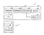
- FIG. 1 is a schematic configuration diagram showing an example of an automatic landing system for a vertical take-off and landing aircraft according to the first embodiment.
- FIG. 2 is an explanatory diagram showing how the vertical take-off and landing aircraft according to the first embodiment heads for the landing target point.
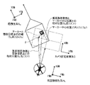
- FIG. 3 is an explanatory diagram showing each coordinate system of the automatic landing system.
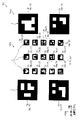
- FIG. 4 is an explanatory diagram showing an example of a marker group.
- FIG. 5 is an explanatory diagram showing an example of a marker included in the marker group.
- FIG. 6 is an explanatory diagram showing an example of a case where only a part of the marker group is reflected in the image in the camera fixed coordinate system.
- FIG. 1 is a schematic configuration diagram showing an example of an automatic landing system for a vertical take-off and landing aircraft according to the first embodiment.
- FIG. 2 is an explanatory diagram showing how the vertical take-off and landing aircraft according to the first embodiment heads for the landing target point.
- FIG. 3 is an explanatory diagram showing each coordinate system
- FIG. 7 is an explanatory diagram showing an example of a case where only a part of the marker group is shown in the image in the ship inertial frame.
- FIG. 8 is an explanatory diagram showing an example of a case where only a part of the marker group is reflected in the image in the ship inertial system.
- FIG. 9 is a flowchart showing an example of a processing procedure of the landing control method of the vertical take-off and landing aircraft according to the first embodiment.
- FIG. 10 is an explanatory diagram showing the landing operation of the vertical take-off and landing aircraft according to the first embodiment.
- FIG. 11 is a flowchart showing an example of the processing procedure in the approach mode.
- FIG. 12 is a flowchart showing an example of the processing procedure in the high altitude hovering mode.
- FIG. 13 is a flowchart showing an example of the processing procedure in the low altitude hovering mode.
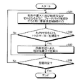
- FIG. 14 is a flowchart showing an example of the processing procedure in the landing mode.
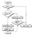
- FIG. 15 is a flowchart showing an example of relative position calculation processing.
- FIG. 16 is a schematic configuration diagram showing an example of an automatic landing system for a vertical take-off and landing aircraft according to the second embodiment.
- FIG. 17 is a flowchart showing an example of the processing procedure of the high altitude hovering mode in the second embodiment.
- FIG. 18 is a flowchart showing an example of the processing procedure of the low altitude hovering mode in the second embodiment.
- FIG. 19 is a schematic configuration diagram showing an automatic landing system according to the third embodiment.
- FIG. 20 is a flowchart showing an example of the processing procedure of the high altitude hovering mode in the third embodiment.
- FIG. 21 is a flowchart showing an example of the processing procedure of the low altitude hovering mode in the third embodiment.
- FIG. 1 is a schematic configuration diagram showing an example of an automatic landing system for a vertical take-off and landing aircraft according to the first embodiment
- FIG. 2 is an explanation showing how the vertical take-off and landing aircraft according to the first embodiment heads for a landing target point. It is a figure.
- the vertical take-off and landing aircraft 1 according to the first embodiment is an air vehicle (for example, a helicopter, a drone, etc.) as a rotary wing aircraft.
- the vertical take-off and landing aircraft 1 is an unmanned aerial vehicle.
- the vertical take-off and landing aircraft 1 may be a manned aircraft as long as it is an air vehicle capable of moving forward, backward, laterally, turning, and hovering.
- the flight control based on the remote manual control is prioritized when the remote manual control is executed during the flight control of the unmanned aerial vehicle by the autopilot.
- the flight control based on the manual maneuver is prioritized when the manual maneuver is executed during the flight control of the manned aircraft by the autopilot.
- the vertical takeoff and landing aircraft 1 is equipped with an automatic landing system 100, and the flight is controlled by the automatic landing system 100 to land at the landing target point 2 shown in FIG.
- the landing target point 2 is provided on the ship 5 as shown in FIG. Therefore, the vertical take-off and landing aircraft 1 lands (més) on the ship 5 as a moving body that moves on the water.
- the landing target point 2 is not limited to the ship 5, and may be provided on a vehicle or the like as a moving body that moves on the ground, or may be provided on a non-moving facility or on the ground.
- the ship 5 is provided with a restraining device for restraining the vertical take-off and landing aircraft 1 when the vertical take-off and landing aircraft 1 is landed at the landing target point 2.
- FIG. 3 is an explanatory diagram showing each coordinate system of the automatic landing system.
- the ship inertial system SG which is the coordinate system in the ship 5
- the aircraft inertial system HG which is the coordinate system in the vertical takeoff and landing aircraft 1
- the camera fixed coordinate system C which is a system, is used.
- the ship inertial frame SG and the aircraft inertial frame HG are three-dimensional Cartesian coordinate systems including X-axis, Y-axis, and Z-axis.
- the camera fixed coordinate system C is a two-dimensional Cartesian coordinate system including an X axis and a Y axis.
- the aircraft is controlled with the center position (Sx, Sy) of the landing target point 2 as the origin, and in the case of the aircraft inertial frame HG , the position of the vertical takeoff and landing aircraft 1 as the origin.
- FIG. 4 is an explanatory diagram showing an example of a marker group.
- FIG. 5 is an explanatory diagram showing an example of a marker included in the marker group. In FIG. 4, it is the position of the marker group 7G shown by the ship inertial system SG, and in FIG. 5, it is the position of the marker shown by the camera fixed coordinate system C.
- the marker group 7G includes a plurality of markers 7. As shown in FIG. 4, in the present embodiment, each marker 7 is, for example, an AR marker color-coded in two colors, black and white, and is a square marker.
- the marker 7 is not limited to the AR marker, and may be any marker that can acquire information for capturing the position of the landing target point 2 by image processing. Further, a plurality of marker groups 7G may be provided on the ship 5, and the vertical take-off and landing aircraft 1 may be guided to a landing target point 2 corresponding to any of the different marker groups 7G.
- the marker group 7G is configured to include a plurality of markers 7. More specifically, the marker group 7G includes a small marker group 72G and a large marker group 74G, as shown in FIG.
- the small marker group 72G includes a small marker 72 (for example, No. 1) provided at the landing target point 2 and a plurality of small markers 72 provided around the landing target point 2.
- the plurality of small markers 72 are arranged side by side so that their center positions are different from each other.
- No. The small marker 72 to be 1 is arranged so that its center position coincides with the center position (Sx, Sy) of the landing target point 2.
- No. The small markers 72 other than 1 are arranged so as to be offset from the center position from the landing target point 2.
- a plurality of small markers 72 are arranged in a matrix.
- FIG 3 shows an example in which a plurality of small markers 72 are arranged in 5 rows and 3 columns, but the number of rows and the number of columns are not particularly limited. Further, the plurality of small markers 72 do not need to be arranged in a matrix, and may be arranged scatteredly around the landing target point 2. That is, the distance between adjacent small markers 72 does not have to be constant.
- the large marker group 74G includes a plurality of large markers 74 having a size larger than that of the small marker 72.
- the large marker 74 is arranged side by side so that the center position is different from that of the small marker 72, and the center positions are different from each other.
- the large marker 74 is arranged off the center from the landing target point 2. Further, the large marker 74 is arranged at a position farther from the landing target point 2 than the small marker 72.
- the large marker 74 is arranged so as to surround the small marker group 72G with the landing target point 2 as the center. Then, in the large marker group 74G, the large markers 74 are arranged in a matrix. FIG.
- the large marker 74 is arranged in 2 rows and 2 columns, but the number of rows and the number of columns are not particularly limited. Further, the plurality of large markers 74 do not need to be arranged in a matrix, and may be arranged scatteredly at positions farther from the landing target point 2 than the small marker group 72G. That is, the distance between adjacent large markers 74 does not have to be constant.
- each marker 7 holds the information of the ID number as an AR marker.
- the ID number a different number is assigned to each of the markers 7.
- the ID number is assigned as smaller as the marker 7 closer to the landing target point 2.
- FIG. 4 shows an example of the ID number.
- the ID number of the small marker 72 arranged so as to coincide with the center of the landing target point 2 is set to "No. 1", and "No. 2" to "No. 15" are assigned to the small markers 72 around the small marker 72. Numbers up to, and numbers from "No. 16" to "No. 19" are assigned to the large marker 74.
- the ID numbers may be exchanged with each other.
- the ID numbers of the large markers 74 may be exchanged with each other. Further, the ID number may be assigned to a larger number as the marker 7 is closer to the landing target point 2.
- the ship 5 includes a navigation device 70, a data transmission device 80, and an operation display unit 90.
- the navigation device 70 is, for example, an inertial navigation system (INS: Inertial Navigation System), and acquires attitude angles, bow orientations, speeds, accelerations, position coordinates, and the like in the pitch direction and roll direction of the ship 5.
- INS Inertial Navigation System
- the navigation device 70 will be described by applying it to an inertial navigation system, but the navigation device 70 is not particularly limited, and any navigation device 70 may be used.
- the navigation device 70 is an inertial navigation system including GPS (Global Positioning System) as a position measurement unit in order to improve the accuracy of position measurement.
- GPS Global Positioning System
- the description will be given by applying to an inertial navigation system including GPS, but the present invention is not particularly limited to GPS, and any position measuring unit capable of accurately measuring the position may be used, for example, a quasi-zenith satellite system is used. If the position can be measured accurately only by the navigation device 70, the position measurement unit such as GPS may be omitted. Further, the navigation device 70 may acquire at least a part of various data by a sensor.
- the data transmission device 80 is included in the automatic landing system 100 described later, and exchanges various signals with the data transmission device 40 mounted on the vertical takeoff and landing aircraft 1 by wireless communication.
- the operation display unit 90 is a user interface in which the operator on board the ship 5 grasps the control status and inputs various instructions.
- the instruction input by the operator by the operation display unit 90 includes, for example, a control mode transition instruction described later. The details of the migration instruction will be described later.
- the instruction input by the operation display unit 90 is transmitted from the data transmission device 80 to the data transmission device 40. Further, the control status of the vertical takeoff and landing aircraft 1 is transmitted from the data transmission device 40 to the data transmission device 80. That is, the data transmission device 40 and the data transmission device 80 are capable of bidirectional communication.
- the automatic landing system 100 of the vertical take-off and landing aircraft is a system that controls the position of the vertical take-off and landing aircraft 1 in order to land the vertical take-off and landing aircraft 1 in flight at the landing target point 2.
- the automatic landing system 100 is mounted on the vertical takeoff and landing aircraft 1.
- the automatic landing system 100 includes a camera 10, a navigation device 20, a control unit 30, and a data transmission device 40.
- the camera 10 is a photographing device mounted on the vertical take-off and landing aircraft 1 via a gimbal (not shown).
- the camera 10 may be a monocular camera, a compound eye camera, an infrared camera, or the like as long as the marker 7 can be photographed.
- the camera 10 is provided to photograph the marker 7 provided at the landing target point 2 from the vertical takeoff and landing aircraft 1.
- the camera 10 is capable of adjusting the shooting direction via a gimbal (not shown).
- the camera 10 is controlled by the control unit 30 so that the shooting range (angle of view) B (see FIG. 2) of the camera 10 faces directly below in the vertical direction, for example.
- the camera 10 may be controlled by the control unit 30 so that the shooting range B faces diagonally forward with respect to the vertical direction. Further, the camera 10 may omit the gimbal, and may be fixed directly below the body of the vertical take-off and landing aircraft 1 so that the shooting direction faces, for example, the lower side in the vertical direction.
- the control unit 30 acquires an image taken by the camera 10 in the camera fixed coordinate system C.
- the navigation device 20 is an inertial navigation system including, for example, a GPS.
- the navigation device 20 may be an inertial navigation system including a position measuring unit such as GPS, or an inertial navigation system omitting a position measuring unit such as GPS, as in the navigation device 70.
- the navigation device 20 including the GPS acquires the attitude angles in the pitch direction and the roll direction of the vertical takeoff and landing aircraft 1, the heading, the aircraft speed of the vertical takeoff and landing aircraft 1, the aircraft acceleration, the position coordinates, and the like.
- the navigation device 20 includes an attitude angle sensor that detects the attitude angle of the vertical takeoff and landing aircraft 1, a speed detection sensor that detects the aircraft speed of the vertical takeoff and landing aircraft 1, an acceleration detection sensor that detects the aircraft acceleration of the vertical takeoff and landing aircraft 1, and vertical. It may have a sensor for detecting the nose direction of the takeoff and landing aircraft 1.
- the navigation device 20 outputs the acquired attitude angle, aircraft speed, aircraft acceleration, and position coordinates of the vertical takeoff and landing aircraft 1 to the control unit 30.
- the automatic landing system 100 includes an altitude sensor 25 that detects the altitude of the vertical takeoff and landing aircraft 1 from the ground surface or the water surface.
- the altitude sensor 25 is, for example, a laser altimeter, and measures the relative altitude ⁇ h (see FIG. 2) from the vertical takeoff and landing aircraft 1 to the landing target point 2.
- a radio wave altimeter may be used, a barometric altimeter may be used, or any altimeter may be used. Further, these altimeters may be appropriately combined and applied according to the usage environment, that is, in order to measure the altitude from the ground surface and the altitude from the sea surface.
- the altitude sensor 25 outputs the detected relative altitude ⁇ h of the vertical takeoff and landing aircraft 1 to the control unit 30.
- the altitude sensor 25 measures the altitude of the vertical take-off and landing aircraft 1 and outputs it to the control unit 30, and the control unit 30 in the guidance calculation unit 34 described later, based on the altitude of the vertical take-off and landing aircraft 1, the landing target point.
- Relative altitude ⁇ h up to 2 may be calculated.
- the automatic landing system 100 is not limited to the altitude sensor 25, but the image processing unit 32 described later performs image processing on the image including the marker 7 taken by the camera 10, so that the vertical takeoff and landing aircraft 1 and the ship 5 can be combined with each other.
- the relative altitude ⁇ h may be calculated.
- the control unit 30 includes an image processing unit 32, a guidance calculation unit 34, and a flight control unit 36.
- the control unit 30 includes a shooting control unit (not shown) that controls the shooting direction of the camera 10 via a gimbal (not shown) provided on the vertical take-off and landing aircraft 1.
- the shooting range B of the camera 10 is adjusted so as to face directly below in the vertical direction.
- the image processing unit 32 performs image processing on the image taken by the camera 10 to calculate the center positions (see FIG. 5) of the small marker 72 and the large marker 74.
- the center position (Cx, Cy) here is a coordinate point in the camera fixed coordinate system C having the center of the image taken by the camera 10 as the origin, and can be calculated from the number of pixels from the center of the image. Specifically, as shown in FIG.
- the image processing unit 32 identifies two diagonal lines Ld extending between the corners of the small marker 72 by image processing, and the intersection of the two specified diagonal lines Ld is the center position. Let it be (Cx, Cy).
- the landing target point 2 is not limited to the center position of the small marker 72, and may be any of the four corners of the small marker 72 or may be a position offset from the center position of the small marker 72.
- the image processing unit 32 may specify only one diagonal line Ld and set the center position of the length of the specified diagonal line Ld as the center position (Cx, Cy). Further, the image processing unit 32 may specify two or more diagonal lines Ld and set a position that is the average of the center positions of the specified diagonal lines Ld as the center position (Cx, Cy). Further, the image processing unit 32 may calculate the center position (Cx, Cy) of the square based on the function when the small square marker 72 is trapezoidally corrected by using the function by the projective transformation. At that time, even if the keystone correction is performed using the coordinate points of the four corners of the small marker 72 or the coordinate points of each point of the boundary color-coded in black and white of the small marker 72, the other coordinate points are calculated by interpolation. good.
- small markers 72 having ID numbers “No. 2”, “No. 8”, “No. 10”, and “No. 14” are included in the image.
- the image processing unit 32 calculates the center position (Cx', Cy') of the small marker 72 by using the marker 7 having the smallest ID number among the recognized plurality of markers 7.
- the center position (Cx', Cy') of the small marker 72 is calculated using the small marker 72 of "No. 2" having the smallest ID number.
- the method for calculating the center position (Cx', Cy') of the small marker 72 is the same as the method for calculating the center of the small marker 72 described above.
- the center position of the small marker 72 is the coordinates ( Sx ', Sy'), and the landing target point 2 is the coordinates (Sx, Sy). It has become.
- the relative positional relationship between the landing target point 2 and the center position (Sx', Sy') of the small marker 72, that is, the distance is (Dx, Dy).
- the example shown in FIG. 8 is a case where the altitude of the vertical take-off and landing aircraft 1 is higher than the example shown in FIG. 5, and the ID numbers are “No. 2”, “No. 8”, “No. 10”, and “No. 10”.
- the small marker 72 of "14" and the large marker 74 of the ID number "No. 18" are reflected in the image.
- the image processing unit 32 cannot recognize each small marker 72 due to the small size of each small marker 72 in the image, and can recognize only the large marker 74.
- the center position of the large marker 74 is the coordinates ( Sx ′′, Sy ′′), and the landing target point 2 is the coordinates (Sx, Sy).
- the relative positional relationship between the landing target point 2 and the center position (Sx ′′, Sy ′′) of the large marker 74, that is, the distance (hereinafter, also referred to as an offset amount) is (Dx, Dy).
- the method of calculating the center position of the large marker 74 in the camera fixed coordinate system C is the same as the method of calculating the center of the small marker 72 described above.
- the image processing unit 32 calculates the relative altitude ⁇ h between the vertical takeoff and landing aircraft 1 and the ship 5 by performing image processing on the image including the marker 7 taken by the camera 10. May be good. Further, the image processing unit 32 identifies the direction of the marker 7 by performing image processing on the image including the marker 7 taken by the camera 10, and sets the heading of the vertical takeoff and landing aircraft 1 acquired by the navigation device 20. By associating, the heading direction of the ship 5 may be calculated. A marker for calculating the bow direction may be separately provided on the ship 5.
- the guidance calculation unit 34 calculates the control amount of the vertical take-off and landing aircraft 1 for guiding the vertical take-off and landing aircraft 1 to the landing target point 2.
- the control amount is a control amount for adjusting the airframe speed, attitude angle, change rate of attitude angle, etc. of the vertical takeoff and landing aircraft 1.
- the guidance calculation unit 34 calculates the relative position (X, Y) between the vertical takeoff and landing aircraft 1 and the landing target point 2 and the relative speed between the vertical takeoff and landing aircraft 1 and the landing target point 2 in order to calculate the control amount.
- the guidance calculation unit 34 has the center positions (Cx', Cy') and (Cx', Cy'') of the small marker 72 or the large marker 74 calculated by the image processing unit 32, and the orientation of the camera 10, that is, vertical takeoff and landing. Vertical based on the nose direction of the aircraft 1, the altitude of the vertical takeoff and landing aircraft 1 (relative altitude ⁇ h with respect to the landing target point 2), and the offset amount (Dx, Dy) of the markers 72 and 74 with respect to the landing target point 2. The relative positions (X, Y) between the takeoff and landing aircraft 1 and the landing target point 2 are calculated.
- the orientation of the camera 10 and the heading of the vertical takeoff and landing aircraft 1 are matched, but the orientation is not particularly limited, and the orientation of the camera 10 and the heading of the vertical takeoff and landing aircraft 1 are not matched. You may.
- the image processing unit 32 and the guidance calculation unit 34 function as a relative position acquisition unit that acquires the relative position between the vertical takeoff and landing aircraft 1 and the landing target point 2.
- the relative position (X, Y) is the distance between the vertical takeoff and landing aircraft 1 and the landing target point 2 in the horizontal direction.
- the guidance calculation unit 34 uses the center positions (Cx', Cy'), (Cx', Cy') of the small marker 72 or the large marker 74 in the camera fixed coordinate system C calculated by the image processing unit 32.
- ⁇ is the center of the vertical take-off and landing aircraft 1 and the markers 72 and 74 in the ship inertial frame SG based on the nose orientation of the vertical take-off and landing aircraft 1 and the altitude of the vertical take-off and landing aircraft 1 (relative altitude ⁇ h with respect to the landing target point 2).
- the ship inertia It is converted into a relative position ( X , Y) between the vertical take-off and landing aircraft 1 and the landing target point 2 in the system SG.
- the guidance calculation unit 34 makes landing with the vertical take-off and landing aircraft 1 in the aircraft inertial system HG based on the nose direction of the vertical take-off and landing aircraft 1 and the altitude of the vertical take-off and landing aircraft 1 (relative altitude ⁇ h with respect to the landing target point 2). It may be directly converted to a relative position (X, Y) with the target point 2.
- the ship inertial frame SG is a coordinate system with the landing target point 2 as the origin, the direction along the bow direction of the ship 5, the direction orthogonal to the head direction of the ship 5 in the horizontal direction, and the vertical direction as the orthogonal axis. be. Further, as shown in FIGS.
- the aircraft inertial system HG has the vertical takeoff and landing aircraft 1 as the origin, the X-axis in the direction along the nose direction of the vertical takeoff and landing aircraft 1, and the nose of the vertical takeoff and landing aircraft 1. It is a coordinate system in which the direction orthogonal to the azimuth in the horizontal direction is the Y axis and the vertical direction is the Z axis.
- the guidance calculation unit 34 has the position coordinates in the earth coordinate system of the vertical takeoff and landing machine 1 acquired by the navigation device 20 and the position coordinates acquired by the navigation device 70 of the ship 5 and obtained by communication of the data transmission devices 40 and 80.
- the relative position (X GPS , Y GPS ) between the vertical takeoff and landing aircraft 1 and the landing target point 2 is calculated based on the position coordinates of the ship 5 in the earth coordinate system. Therefore, the guidance calculation unit 34 is based on the position coordinates of the vertical takeoff and landing machine 1 acquired by GPS and the position coordinates of the ship 5 provided with the landing target point 2 acquired by the data transmission device 40. It functions as a second relative position acquisition unit that calculates the relative position (X GPS , Y GPS ) between 1 and the landing target point 2.
- the control unit 30 stores in advance the distance (Dx, Dy) from the center of each marker 7 to the landing target point 2 in a storage unit (not shown).
- the guidance calculation unit 34 is based on the center position (Cx', Cy') of the small marker 72 of "No. 2" calculated by the image processing unit 32.
- the relative position ( X ', Y') between the vertical takeoff and landing aircraft 1 and the center position (Sx', Sy') of the small marker 72 in the inertial frame SG is calculated.
- the guidance calculation unit 34 adds the distance (Dx, Dy) stored in advance to the calculated relative position ( X ', Y') as an offset amount, so that the vertical takeoff and landing aircraft in the ship inertial system SG
- the relative position (X, Y) between 1 and the center position (Sx, Sy) of the landing target point 2 is calculated.
- the guidance calculation unit 34 adds the distance (Dx, Dy) stored in advance to the calculated relative position ( X ', Y') as an offset amount, so that the vertical takeoff and landing aircraft in the ship inertial system SG
- the relative position (X, Y) between 1 and the center position (Sx, Sy) of the landing target point 2 is calculated.
- the small marker 72 No. 1
- it can be said that the distance (Dx, Dy) is 0.
- the small marker 72 (No. 1) is arranged so as to coincide with the center position (Sx, Sy) of the landing target point 2, but this configuration is not essential and all the small marker group 72G are landed. It may be composed of a small marker 72 shifted from the center position (Sx, Sy) of the target point 2.
- the guidance calculation unit 34 uses the large marker 74 of “No. 18” with the smallest ID number recognized in the image to determine the relative position between the vertical takeoff and landing aircraft 1 and the center position (Sx, Sy) of the landing target point 2.
- Calculate (X, Y) That is, as described above, the guidance calculation unit 34 and the vertical takeoff and landing aircraft 1 in the ship inertial frame SG are based on the center position (Cx ′′, Cy ′′) of the large marker 74 calculated by the image processing unit 32.
- the relative position (X', Y') with the center position (Sx', Sy') of the large marker 74 is calculated.
- the guidance calculation unit 34 adds the distance (Dx, Dy) stored in advance to the calculated relative position (X', Y') as an offset amount, so that the vertical takeoff and landing aircraft 1 and the landing target point 2 are added.
- the relative position (X, Y) with respect to the center position (Sx, Sy) of is calculated.
- the relative calculation method offsets to the center position (Sx, Sy) of the landing target point 2 by the above calculation method.
- the position (X, Y) can be calculated.
- the relative position (X, Y) can be calculated based on the marker 7 photographed by the camera 10. That is, when calculating the relative position (X, Y), it is not necessary to perform data communication with the ship 5 side. As a result, when the vertical take-off and landing aircraft 1 is controlled based on the relative position (X, Y), it is not affected by errors due to the navigation devices 20 and 70, so that the position accuracy can be improved and the communication can be performed. It is possible to suppress the deterioration of the responsiveness of the flight control due to the above. Therefore, the vertical take-off and landing aircraft 1 can be landed at the landing target point 2 with higher accuracy. Then, by accurately controlling the position of the vertical take-off and landing aircraft 1 with respect to the landing target point 2, it is possible to prevent the vertical take-off and landing aircraft 1 from interfering with devices and structures provided in the vicinity of the landing target point 2. Can be done.
- the guidance calculation unit 34 calculates the relative speed between the vertical takeoff and landing aircraft 1 and the landing target point 2. Therefore, the guidance calculation unit 34 functions as a relative speed acquisition unit that acquires the relative speed between the vertical takeoff and landing aircraft 1 and the landing target point 2. More specifically, the guidance calculation unit 34 calculates the relative speed from, for example, the difference between the hull speed of the vertical takeoff and landing aircraft 1 acquired by the navigation devices 20 and 70 and the hull speed of the ship 5. Further, the induction calculation unit 34 may calculate the relative velocity based on the pseudo-differentiation of the relative position (X, Y). Further, the guidance calculation unit 34 calculates the relative direction between the heading of the vertical take-off and landing aircraft 1 and the heading of the ship 5.
- the guidance calculation unit 34 calculates the relative altitude ⁇ h up to the landing target point 2 based on the altitude of the vertical takeoff and landing aircraft 1 detected by the altitude sensor 25. Therefore, the altitude sensor 25 and the guidance calculation unit 34 function as a relative altitude acquisition unit that acquires the relative altitude ⁇ h between the vertical takeoff and landing aircraft 1 and the landing target point 2.
- the image processing unit 32 performs image processing on the image including the marker 7 taken by the camera 10 to calculate the relative altitude ⁇ h between the vertical takeoff and landing aircraft 1 and the ship 5
- the image processing unit 32 is relative. It becomes the altitude acquisition department.
- the guidance calculation unit 34 calculates the control amount by feedback control (for example, PID control) based on the relative position (X, Y), relative velocity, relative direction, and aircraft acceleration.
- the guidance calculation unit 34 calculates the control amount of the vertical takeoff and landing aircraft 1 by feedback control so that the relative position (X, Y) and the relative direction become zero.
- the guidance calculation unit 34 may calculate the control amount of the vertical takeoff and landing aircraft 1 by feedback control so that the relative speed is within the predetermined speed and the aircraft acceleration is within the predetermined acceleration. Within a predetermined speed and within a predetermined acceleration, the range is such that the vertical take-off and landing aircraft 1 can be said to be able to fly stably at a predetermined relative altitude ⁇ h.
- the predetermined velocity is zero
- the predetermined acceleration is zero
- the guidance calculation unit 34 outputs the calculated control amount to the flight control unit 36.
- the guidance calculation unit 34 controls the vertical take-off and landing aircraft 1 in a plurality of control modes in order to guide the vertical take-off and landing aircraft 1 to the landing target point and land.
- the plurality of control modes include an approach mode, a hovering mode including a high altitude hovering mode and a low altitude hovering mode, and a landing mode. Details of each control mode will be described later.
- the automatic landing system 100 controls so that the relative position (X, Y) becomes zero, but in reality, the relative position includes an error after the vertical takeoff and landing aircraft 1 lands on the ship 5. It does not always reach zero, and the positions of the vertical takeoff and landing aircraft 1 and the landing target point 2 do not completely match.
- the flight control unit 36 controls each component of the vertical take-off and landing aircraft 1 according to the control amount calculated by the guidance calculation unit 34, which will be described later, to fly the vertical take-off and landing aircraft 1.
- the flight control unit 36 controls the blade pitch angle, rotation speed, etc. of each rotor according to the controlled amount, and adjusts the airframe speed, attitude angle, change rate of attitude angle, etc. of the vertical takeoff and landing aircraft 1.
- the vertical take-off and landing aircraft 1 is guided to the landing target point 2.
- the image processing unit 32 and the guidance calculation unit 34 are described as functional units different from the flight control unit 36, but the flight control unit 36, the image processing unit 32, and the guidance calculation unit 34 are integrated. It may be a functional unit. That is, the flight control unit 36 may process the image processing unit 32 and the guidance calculation unit 34.
- FIG. 9 is a flowchart showing an example of a processing procedure of the landing control method of the vertical take-off and landing aircraft according to the first embodiment.
- FIG. 10 is an explanatory diagram showing the landing operation of the vertical take-off and landing aircraft according to the first embodiment.
- FIG. 11 is a flowchart showing an example of the processing procedure in the approach mode.
- FIG. 12 is a flowchart showing an example of the processing procedure in the high altitude hovering mode.
- FIG. 13 is a flowchart showing an example of the processing procedure in the low altitude hovering mode.
- FIG. 14 is a flowchart showing an example of the processing procedure in the landing mode.
- FIG. 15 is a flowchart showing an example of relative position calculation processing. The processes shown in FIGS. 9 to 15 are executed by the guidance calculation unit 34.
- the vertical take-off and landing aircraft 1 executes a plurality of control modes in a series of landing operations for landing (landing) on a ship 5 from a flight state.
- the vertical take-off and landing aircraft 1 has a step S1 for executing the approach mode, a step S2 for executing the high altitude hovering mode, a step S3 for executing the low altitude hovering mode, and a step S4 for executing the landing mode.
- a series of landing operations are performed.
- the vertical take-off and landing aircraft 1 performs a step (step S17 described later) of interrupting the execution of the high altitude hovering mode and the low altitude hovering mode and executing the emergency mode in which the landing operation is interrupted.
- the approach mode is a mode in which the vertical take-off and landing aircraft 1 is made to enter the deck of the ship 5 and the vertical take-off and landing aircraft 1 is hovered on the landing target point 2 by a command from the ship 5.
- the vertical takeoff and landing aircraft 1 captures the marker group 7G on the deck with the camera 10, and the landing target point 2 is hovering so as to be in the center of the shooting range (angle of view) B of the camera 10. It has become.
- the low altitude hovering mode is a mode in which the vertical takeoff and landing aircraft 1 descends and hovering at a lower altitude than the high altitude hovering mode.
- the landing mode is a mode in which the vertical takeoff and landing aircraft 1 lands at the landing target point 2.
- the emergency mode is a mode in which the landing operation of the vertical take-off and landing aircraft 1 on the ship 5 is interrupted and the ship rises.
- the vertical take-off and landing aircraft 1 executes a landing operation on the ship 5 by executing these control modes. Next, each control mode will be specifically described with reference to FIGS. 11 to 15.
- the guidance calculation unit 34 executes the approach mode as step S1.
- the approach mode will be described in detail with reference to FIG.
- the guidance calculation unit 34 calculates (generates) relative positions (X GPS , Y GPS ) from the navigation devices 20, 70, that is, the position coordinates obtained by GPS.
- the guidance calculation unit 34 determines whether or not the approach mode button is turned on as step S32.
- the approach mode button is a button for inputting a control mode transition instruction provided on the operation display unit 90 of the ship 5, and is turned on and off by an operator on board the ship 5. The operator turns on the approach mode button when the vertical take-off and landing aircraft 1 is ready to land on ship 5.
- the control unit 30 determines that the approach mode button is not turned on (No in step S32)
- the control unit 30 continues the process of step S1.
- the control unit 30 determines that the approach mode button is on (Yes in step S32)
- the control unit 30 proceeds to the process of step S33.
- step S33 the guidance calculation unit 34 executes feedback control so that the relative position (X GPS , Y GPS ) generated in step S31 becomes zero.
- the guidance calculation unit 34 causes the vertical takeoff and landing aircraft 1 to fly toward the landing target point 2 in the horizontal direction.
- the guidance calculation unit 34 executes feedback control so that the calculated relative direction between the heading of the vertical take-off and landing aircraft 1 and the heading of the ship 5 becomes zero as an example.
- the guidance calculation unit 34 makes the vertical takeoff and landing aircraft 1 fly so that the heading of the vertical takeoff and landing aircraft 1 coincides with the heading of the ship 5.
- the guidance calculation unit 34 executes feedback control so that the relative direction becomes zero, but the relative direction is not particularly limited and may not be zero.
- the guidance calculation unit 34 executes feedback control so that the relative altitude ⁇ h measured by the altitude sensor 25 becomes the first relative altitude ⁇ h1.
- the guidance calculation unit 34 keeps the vertical takeoff and landing aircraft 1 at the first relative altitude ⁇ h1 while descending from the initial altitude to the first relative altitude ⁇ h1 (see FIG. 2) in the vertical direction.
- the first relative altitude ⁇ h1 is, for example, 20 m.
- the vertical take-off and landing aircraft 1 is controlled so that the relative position (X GPS , Y GPS ) becomes zero so that the vertical take-off and landing aircraft 1 is within a predetermined range of the landing target point 2. Is in flight control.
- the guidance calculation unit 34 executes the image relative position calculation process as step S34, and calculates the relative position (X, Y) as the horizontal distance between the vertical takeoff and landing aircraft 1 and the landing target point 2. The details of the image relative position calculation process will be described later.
- step S35 the guidance calculation unit 34 determines whether the relative position (X, Y) as the horizontal distance between the vertical takeoff and landing aircraft 1 and the landing target point 2 calculated in step S34 is within the first threshold value. Judge whether or not.
- the first threshold value is set by the camera 10 as a value sufficient to keep capturing the landing target point 2.
- the guidance calculation unit 34 re-executes the processes after step S33. That is, the vertical take-off and landing aircraft 1 cannot capture the landing target point 2 by the camera 10, in other words, it is assumed that the landing target point 2 is not sufficiently close to the landing target point 2, and the processes after step S33 are executed again.
- the guidance calculation unit 34 repeatedly executes the processes after step S33 until the vertical take-off and landing aircraft 1 reaches a distance sufficient for the camera 10 to continue to capture the landing target point 2.
- the guidance calculation unit 34 determines that the relative position (X, Y) is within the first threshold value (Yes in step S35)
- the vertical takeoff and landing aircraft 1 continues to capture the landing target point 2 by the camera 10. It is assumed that the distance is sufficient, that is, the landing target point 2 is sufficiently close to the landing target point 2, and the approach mode is terminated and the next control mode is started.
- the high altitude hovering mode is executed as step S2.
- the high altitude hovering mode will be described in detail with reference to FIG.
- the guidance calculation unit 34 executes feedback control so that the relative position (X, Y) calculated by the image relative position calculation process becomes zero, as shown in step S41 of FIG. .. Further, the guidance calculation unit 34 executes feedback control so that the calculated relative direction between the heading of the vertical take-off and landing aircraft 1 and the heading of the ship 5 becomes zero as an example. Further, the guidance calculation unit 34 executes feedback control so that the relative altitude ⁇ h measured by the altitude sensor 25 becomes the first relative altitude ⁇ h1.
- the guidance calculation unit 34 keeps the vertical takeoff and landing aircraft 1 at the first relative altitude ⁇ h1 while hovering just above the landing target point 2 in the vertical direction. Then, the guidance calculation unit 34 executes the image relative position calculation process again in step S42.
- step S43 the guidance calculation unit 34 determines whether or not the relative position (X, Y) calculated in step S42 is within the second threshold value, and whether or not the low altitude hovering mode button is turned on.
- the second threshold value is set as a value that is equal to or less than the first threshold value in the approach mode.
- the low altitude hovering mode button is a button for inputting a control mode transition instruction provided on the operation display unit 90 of the ship 5, and is turned on and off by an operator on board the ship 5.
- Step S43 determines whether or not the first condition for shifting from the high altitude hovering mode to the low altitude hovering mode is satisfied. That is, in the first embodiment, the first condition includes that the relative position (X, Y) is within the second threshold value and that the operator has instructed the mode to shift to the low altitude hovering mode. ..
- the guidance calculation unit 34 determines that the relative position (X, Y) is not within the second threshold value (No in step S43). Further, even when the guidance calculation unit 34 determines that the low altitude hovering mode button is not turned on (No in step S43), the process after step S41 is executed again. Then, the guidance calculation unit 34 repeatedly executes the processes after step S41 until the vertical takeoff and landing aircraft 1 has a relative position (X, Y) with respect to the landing target point 2 within the second threshold value. When the guidance calculation unit 34 determines that the relative position (X, Y) is within the second threshold value and the low altitude hovering mode button is turned on (Yes in step S43), the high altitude hovering mode And move to the next control mode.
- the guidance calculation unit 34 executes the low altitude hovering mode as step S3.
- the low altitude hovering mode will be described in detail with reference to FIG.
- the guidance calculation unit 34 executes feedback control so that the relative position (X, Y) calculated by the image relative position calculation process becomes zero, as shown in step S51 of FIG. ..
- the guidance calculation unit 34 executes feedback control so that the calculated relative direction between the heading of the vertical take-off and landing aircraft 1 and the heading of the ship 5 becomes zero as an example.
- the guidance calculation unit 34 feedback-controls so that the relative altitude ⁇ h measured by the altitude sensor 25 becomes the second relative altitude ⁇ h2 lower than the first relative altitude ⁇ h1. As a result, the guidance calculation unit 34 lowers the altitude of the vertical takeoff and landing aircraft 1 to the second relative altitude ⁇ h2 (see FIG. 2) while hovering the vertical takeoff and landing aircraft 1 immediately above the landing target point 2.
- the second relative altitude ⁇ h2 is, for example, 3 m.
- the guidance calculation unit 34 sets the descent speed of the vertical takeoff and landing aircraft 1 as the first descent speed.
- the first descent speed is, for example, 0.6 m / s. Then, the guidance calculation unit 34 executes the image relative position calculation process again in step S52.
- step S53 the guidance calculation unit 34 determines whether or not the relative position (X, Y) calculated in step S52 is within the third threshold value (predetermined threshold value), and the landing mode button is turned on. Determine if it is.
- the third threshold value is set as a value that is equal to or less than the second threshold value in high altitude hovering.
- the landing mode button is a button for inputting a control mode transition instruction provided on the operation display unit 90 of the ship 5, and is turned on and off by an operator on board the ship 5. The operator visually confirms whether the vertical take-off and landing aircraft 1 is able to fly stably at the second relative altitude ⁇ h2, and turns on the landing mode button when the vertical take-off and landing aircraft 1 is able to fly stably. ..
- Step S53 determines whether or not the second condition (predetermined condition) for shifting from the low altitude hovering mode to the landing mode is satisfied. That is, in the first embodiment, the second condition includes that the relative position (X, Y) is within the third threshold value and that the operator has instructed the mode transition to the landing mode. The operator may turn on the landing mode button even when the vertical take-off and landing aircraft 1 is not stable.
- the guidance calculation unit 34 determines that the relative position (X, Y) is not within the third threshold value (No in step S53). Further, even when the guidance calculation unit 34 determines that the landing mode button is not turned on (No in step S53), the process after step S51 is executed again. Then, the guidance calculation unit 34 causes the vertical take-off and landing aircraft 1 to descend to the second relative altitude ⁇ h2 while the position (X, Y) relative to the landing target point 2 is within the third threshold value. In addition, the processes after step S51 are repeatedly executed.
- the guidance calculation unit 34 determines that the relative position (X, Y) is within the third threshold value and the landing mode button is turned on (Yes in step S53), the guidance calculation unit 34 ends the low altitude hovering mode. Then, it shifts to the next control mode.
- the guidance calculation unit 34 executes the landing mode as step S4.
- the landing mode will be described in detail with reference to FIG.
- the guidance calculation unit 34 executes feedback control so that the relative position (X, Y) calculated by the image relative position calculation process becomes zero.
- the guidance calculation unit 34 executes feedback control so that the calculated relative direction between the heading of the vertical take-off and landing aircraft 1 and the heading of the ship 5 becomes zero as an example.
- the guidance calculation unit 34 executes vertical speed control in which the descent rate is constant until the relative altitude ⁇ h measured by the altitude sensor 25 becomes the third relative altitude ⁇ h3.
- the descent rate is the degree of altitude that descends per unit time.
- the guidance calculation unit 34 uses the descent speed of the vertical takeoff and landing aircraft 1 as the second descent speed. As a result, the guidance calculation unit 34 lowers the relative altitude ⁇ h of the vertical takeoff and landing aircraft 1 to the third relative altitude ⁇ h3 (see FIG. 2).
- the third relative altitude ⁇ h3 is, for example, 10 cm.
- the second descent speed is, for example, 1.0 m / s.
- the second descent speed is set to be larger than the first descent speed, but the first descent speed and the first descent speed are set.
- the descent speed may be set to a large value or may be the same value. Further, when the altitude of the vertical take-off and landing aircraft 1 reaches the third relative altitude ⁇ h3, the guidance calculation unit 34 keeps the control amount regarding the attitude angle of the vertical take-off and landing aircraft 1 when the altitude reaches the third relative altitude ⁇ h3. Further lower the vertical takeoff and landing aircraft 1. It should be noted that not only the attitude angle but also the control amounts related to the relative position (X, Y), the relative direction, and the relative velocity are all held, not all held, or partially held. , The vertical takeoff and landing aircraft 1 may be landed at the landing target point 2.
- step S62 the guidance calculation unit 34 determines whether or not the camera 10 has captured at least one marker 7, that is, whether or not the landing target point 2 has been captured. Whether or not at least one marker 7 can be captured by the camera 10 can be calculated by the same processing as in step S12 of the image relative position calculation processing described later.
- the guidance calculation unit 34 calculates the relative position (X, Y) by image processing in step S63.
- the relative positions (X, Y) can be calculated by the same processing as in step S14 of the image relative position calculation processing described later.
- step S63 is omitted and the process proceeds to step S64.
- the execution of the landing mode may be interrupted based on the judgment of the pilot during the execution of the landing mode.
- the flight control unit 36 determines in step S64 whether or not the vertical takeoff and landing aircraft 1 has landed at the landing target point 2. Whether or not the vertical take-off and landing aircraft 1 has landed at the landing target point 2 can be determined, for example, by providing a contact-type sensor on a leg (not shown) of the vertical take-off and landing aircraft 1.
- the flight control unit 36 executes the processes after step S61 again. As a result, the vertical take-off and landing aircraft 1 is controlled to descend by the procedure of step S61 until the vertical take-off and landing aircraft 1 lands at the landing target point 2.
- step S64 when the flight control unit 36 determines that the vertical takeoff and landing aircraft 1 has landed at the landing target point 2 (Yes in step S64), the guidance calculation unit 34 ends the landing mode. As a result, the processing routine shown in FIG. 9 is also terminated.
- the guidance calculation unit 34 determines in step S11 whether or not the emergency mode button is turned off.
- the emergency mode button is provided on the operation display unit 90 of the ship 5, and is turned on and off by an operator on board the ship 5.
- the emergency mode button is turned on. Specifically, the operator turns on the emergency mode button when it is visually confirmed that the flight state of the vertical take-off and landing aircraft 1 is unstable due to, for example, the influence of wind or the occurrence of some kind of failure.
- step S11 When the guidance calculation unit 34 determines in step S11 that the emergency mode button is turned on (No in step S11), the guidance calculation unit 34 shifts to the execution of the emergency mode as step S17.
- the guidance calculation unit 34 raises the vertical take-off and landing aircraft 1 to a predetermined altitude (for example, 20 m) sufficiently away from the ship 5 to maintain the current relative position (X, Y).
- the guidance calculation unit 34 can execute the emergency mode during the execution of step S2 for executing the high altitude hovering mode shown in FIG. 9 and step S3 for executing the low altitude hovering mode.
- the guidance calculation unit 34 restarts the process shown in FIG. 9 from step S1.
- the guidance calculation unit 34 determines whether or not at least one marker 7 can be captured by the camera 10 in step S12. Whether or not at least one marker 7 can be captured by the camera 10 is determined by the center position (Cx', Cy'), (Cx',', of the small marker 72 or the large marker 74 in the image taken by the camera 10. It can be determined whether or not information that can calculate Cy ′′) is obtained. That is, it can be determined whether or not at least one of the plurality of markers 7 included in the marker group 7G can be recognized by image processing within the range of the image captured by the camera 10.
- the guidance calculation unit 34 determines that the camera 10 has captured at least one marker 7 (Yes in step S12), the target non-capture counter is set to a value of 0 in step S13. Then, as step S14, the guidance calculation unit 34 sets the center position (Cx', Cy'), (Cx', Cy'') of the small marker 72 or the large marker 74 and the orientation of the camera 10 (that is, the same orientation).
- the relative position (X, Y) between the vertical take-off and landing aircraft 1 and the landing target point 2 is calculated based on.
- the relative positions (X, Y) are the center positions (Cx ′, Cy ′), (Cx ′′ ′ ′) of the small marker 72 or the large marker 74 in the camera fixed coordinate system C calculated by the image processing unit 32. , Cy ′′), the relative position ( X ′, ′ ′′) of the vertical take-off and landing aircraft 1 and the center positions (Sx ′, Sy ′), (Sx ′′, Sy ′′) of the markers 72 and 74 in the ship inertial frame SG.
- step S12 determines in step S12 that the camera 10 has not captured any of the markers 7 (No in step S12)
- the guidance calculation unit 34 adds a value 1 to the target non-capture counter as step S15.
- step S16 it is determined whether or not the target non-capture counter is within a predetermined value.
- the guidance calculation unit 34 executes the processing after step S11 again (the processing of FIG. 15 is executed again).
- the guidance calculation unit 34 determines that the target non-capture counter is not within the predetermined value (No in step S16)
- the process proceeds to step S17, and the process proceeds to the execution of the emergency mode. That is, the guidance calculation unit 34 determines that the time during which even one marker 7 cannot be continuously captured by the camera 10 has reached a predetermined time or longer because the target non-capture counter exceeds a predetermined value, and executes the emergency mode.
- the automatic landing system 100 of the vertical take-off and landing aircraft includes a camera 10 (photographing device) mounted on the vertical take-off and landing aircraft 1 and a marker provided at the landing target point 2 by the camera 10.
- An image processing unit 32 and a guidance calculation unit 34 that perform image processing on the image taken of the group 7G and acquire the relative positions (X, Y) between the vertical takeoff and landing aircraft 1 and the landing target point 2.
- a control unit 30 for controlling the vertical take-off and landing aircraft 1 so that the relative positions (X, Y) become zero is provided, and the marker group 7G includes a plurality of markers 7 provided side by side at different center positions from each other.
- the marker 7 is larger as it is located farther from the landing target point 2, and the image processing unit 32 and the guidance calculation unit 34 are the distance between the marker 7 recognized in the image and the landing target point 2 (Dx, The relative position (X, Y) is acquired based on Dy).
- the landing target point 2 when the landing target point 2 is provided on a moving body such as a ship 5, the moving body is shaken, or a gust is generated around the vertical takeoff and landing machine 1. Even if the above occurs, it becomes easy to capture any one of the plurality of markers 7 included in the marker group 7G in the image. Further, since the marker 7 is as large as the marker 7 placed at a position away from the landing target point 2, even when the altitude of the vertical takeoff and landing aircraft 1, that is, the distance to the marker group 7G is relatively large, the marker 7 having a large size is imaged. It will be easier to recognize within. Therefore, the landing target point 2 can be captured more stably from the vertical take-off and landing aircraft 1.
- the vertical take-off and landing aircraft 1 the automatic landing system 100 of the vertical take-off and landing aircraft 1, and the automatic landing method of the vertical take-off and landing aircraft 1, the vertical take-off and landing aircraft 1 can be more stably moved to the landing target point 2. It becomes possible to induce.
- the marker group 7G includes a small marker 72 and a large marker 74 arranged at a position farther from the landing target point 2 than the small marker 72.
- the marker group 7G may include the markers 7 having three or more sizes. In that case, it is preferable that the larger marker 7 is arranged at a position farther from the landing target point 2. Further, the marker group 7G may be composed of only a marker 7 having a single size.
- a different ID number is assigned to each marker 7, and the image processing unit 32 and the guidance calculation unit 34 acquire the ID number from the marker 7 recognized in the image and correspond to the ID number.
- the relative position (X, Y) is acquired based on the distance (Dx, Dy) between the marker 7 stored in advance and the landing target point 2.
- the ID number is assigned as smaller as the marker 7 closer to the landing target point 2, and the image processing unit 32 and the guidance calculation unit 34 have the marker 7 with the smallest ID number recognized in the image and the landing target point 2.
- the relative position (X, Y) is acquired based on the distance (Dx, Dy) from. With this configuration, the marker 7 arranged at a position close to the landing target point 2 can be easily determined by the size of the ID number. Further, it is possible to accurately obtain a relative position (X, Y) offset to the center position (Sx, Sy) of the landing target point 2 based on the distance (Dx, Dy) between the marker 7 and the landing target point 2. It will be possible.
- a marker 7 closer to the landing target point 2 is assigned a larger number, and the image processing unit 32 and the guidance calculation unit 34 have the marker 7 with the largest ID number recognized in the image and the landing target point 2.
- the relative position (X, Y) may be acquired based on the distance (Dx, Dy) from.
- any marker 7 may be used, but it is preferable to preferentially use the marker 7 near the center of the image.
- the relative position (X, Y) offset to the center position (Sx, Sy) of the landing target point 2 can be calculated more accurately without being affected by the distortion in the vicinity of the image edge. ..
- the image processing unit 32 and the guidance calculation unit 34 calculate the relative position (X, Y) based on the distance (Dx, Dy) from the landing target point 2 for each of the markers 7 recognized in the image.
- the average value of all the calculated relative positions (X, Y) may be acquired as the final relative position (X, Y). More specifically, in the image processing unit 32, for each of the markers 7 recognized in the image, one by one, the relative position (X, Sy) offset to the center position (Sx, Sy) of the landing target point 2 by the above-mentioned method. Y) is calculated. Then, the average value of all the calculated relative positions (X, Y) is acquired as the final relative position (X, Y) at that time.
- the relative positions (X, Y) can be acquired more accurately based on all the markers 7 recognized in the image. Further, since all the markers 7 recognized in the image are used, it is not necessary to set in advance which marker 7 is preferentially used, and the ID number of each marker 7 can be arbitrarily set. Become.
- the marker 7 may hold information on the distance (Dx, Dy) from the landing target point 2 instead of the information on the ID number.
- the image processing unit 32 acquires information on the distance (Dx, Dy) from the landing target point 2 by image processing from any of the markers 7 recognized in the image, and the acquired distance (Dx, Dy). ), The relative position (X, Y) offset to the center position (Sx, Sy) of the landing target point 2 is calculated.
- any marker 7 may be used, but it is preferable to preferentially use the marker 7 close to the landing target point 2.
- FIG. 16 is a schematic configuration diagram showing an example of an automatic landing system for a vertical take-off and landing aircraft according to the second embodiment.
- the automatic landing system 200 according to the second embodiment has a configuration in which the data transmission device 40 is omitted from the automatic landing system 100.
- the automatic landing system 200 includes a guidance calculation unit 34A instead of the guidance calculation unit 34. Since the other configurations of the automatic landing system 200 are the same as those of the automatic landing system 100, the description thereof is omitted, and the same components are designated by the same reference numerals. Further, since the guidance calculation unit 34A has the same functions as the guidance calculation unit 34 except for the portion described below, the description of the same functions will be omitted.
- the ship 5 does not need to include the data transmission device 80 and the operation display unit 90.
- the navigation device 70 is omitted in FIG. 16 because it does not require the exchange of data acquired by the navigation device 70 between the vertical take-off and landing aircraft 1 and the ship 5.
- the automatic landing system 200 does not perform data communication with the ship 5 side. Therefore, when calculating the relative speed, the hull speed cannot be obtained from the ship 5. Therefore, in the second embodiment, the guidance calculation unit 34 calculates the relative speed based on the relative position (X, Y) between the vertical takeoff and landing aircraft 1 and the landing target point 2. Specifically, the induction calculation unit 34A calculates the relative velocity by pseudo-differentiating the relative positions (X, Y).
- the guidance calculation unit 34A does not execute the process of step S1 in the flowchart shown in FIG. 9, and takes off and landing vertically to the extent that the marker 7 is captured in the shooting range B of the camera 10 by another method. Bring the aircraft 1 closer to the vessel 5, that is, the landing target point 2.
- a laser irradiation device is mounted on the vertical take-off and landing aircraft 1, the laser is irradiated toward the ship 5, and the reflected wave is received on the vertical take-off and landing aircraft 1 side.
- a method of acquiring a relative position with the ship 5 and guiding the vertical take-off and landing aircraft 1 to the ship 5 (landing target point 2) based on the relative position can be mentioned.
- FIG. 17 is a flowchart showing an example of the processing procedure of the high altitude hovering mode in the second embodiment.
- FIG. 18 is a flowchart showing an example of the processing procedure of the low altitude hovering mode in the second embodiment.
- step S41A and step S42A in FIG. 17 are the same processes as in step S41 and step S42 in FIG. 12, description thereof will be omitted.
- the image relative position calculation process is the same as the process shown in FIG.
- the relative position (X, Y) calculated in step S42A, the change rate of the attitude angle (pitch direction and roll direction) of the vertical takeoff and landing aircraft 1, and the relative speed correspond to the first.
- the corresponding first determination threshold of the relative position (X, Y) is the second threshold in the first embodiment.
- the corresponding first determination threshold value of the change rate of the posture angle and the relative speed is set individually for each parameter.
- the first determination threshold value corresponding to the change rate of the attitude angle and the relative speed is provided in place of the operator turning on the low altitude hovering mode button in the first embodiment. Therefore, the first determination threshold value corresponding to the change rate of the attitude angle and the relative speed is set so as to satisfy that the vertical takeoff and landing aircraft 1 can be said to be able to fly stably at the first relative altitude ⁇ h1. Will be done.
- the processing after step S41A is executed again. .. Further, even when it is determined that the change rate of the posture angle and the relative speed are not within the corresponding first determination threshold value (No in step S43A), the guidance calculation unit 34A executes the processing after step S41A again.
- the guidance calculation unit 34A has determined that the relative position (X, Y) is within the second threshold value, and the change rate of the posture angle and the relative speed are within the corresponding first determination threshold value.
- the high altitude hovering mode is terminated and the mode shifts to the low altitude hovering mode.
- Step S43A determines whether or not the first condition for shifting from the high altitude hovering mode to the low altitude hovering mode is satisfied. That is, in the second embodiment, the first condition is that the relative position (X, Y) is within the second threshold value, and the change rate of the posture angle and the relative speed are within the corresponding first determination threshold value. Including being.
- step S51A and step S52A of FIG. 18 are the same processes as step S51 and step S52 of FIG. 13 in the first embodiment, the description thereof will be omitted.
- step S53A the guidance calculation unit 34A determines the relative position (X, Y) calculated in step S52A, the change rate of the attitude angle (pitch direction and roll direction) of the vertical takeoff and landing aircraft 1, the relative direction, the relative speed, and the attitude angle. It is determined whether or not the (roll direction, pitch direction), the horizontal angle (roll direction, pitch direction) of the landing target point 2 and the relative altitude ⁇ h are within the corresponding second determination threshold value.
- the corresponding second determination threshold value of the relative position (X, Y) is the third threshold value in the first embodiment.
- the second determination threshold value of the relative altitude ⁇ h is the second relative altitude ⁇ h2.
- the second determination threshold value of the relative altitude ⁇ h is provided to automatically determine that the vertical takeoff and landing aircraft 1 has descended to the second relative altitude ⁇ h2 and is stable in the low altitude hovering mode.
- the second determination threshold value corresponding to the change rate of the attitude angle of the vertical takeoff and landing aircraft 1, the relative orientation, the relative speed, the attitude angle, and the horizontal angle of the landing target point 2 is set individually for each parameter. ..
- the horizontal angle of the landing target point 2 is the horizontal angle of the surface provided with the landing target point 2 of the ship 5, and the image of the marker 7 taken by the camera 10 in the image processing unit 32. It can be calculated by performing image processing.
- the second determination threshold value corresponding to the change rate of the attitude angle, the relative direction, the relative speed, the attitude angle, and the horizontal angle of the landing target point 2 is that the operator turns on the landing mode button in the first embodiment. It is provided instead.
- the second determination threshold value corresponding to the change rate of the attitude angle, the relative orientation, the relative speed, the attitude angle, and the horizontal angle of the landing target point 2 is stable for the vertical takeoff and landing aircraft 1 at the second relative altitude ⁇ h2. It is set to satisfy the condition that it can be said that it can fly.
- the second determination threshold value of the change rate of the posture angle and the relative speed may be smaller than the first determination threshold value or may be the same value as the first determination threshold value. ..
- the processing after step S51A is executed again. .. Further, when the guidance calculation unit 34A determines that the relative altitude ⁇ h is not within the corresponding first determination threshold value, that is, the second relative altitude ⁇ h2 (No in step S53A), the processing after step S51A is executed again. Further, when the guidance calculation unit 34A determines that the change rate of the attitude angle, the relative direction, the relative speed, the attitude angle, and the horizontal angle of the landing target point 2 are not within the corresponding second determination threshold value (step S53A). In No), the processes after step S51A are executed again.
- the relative position (X, Y) is within the second determination threshold value, that is, the third threshold value, the relative altitude ⁇ h is within the second relative altitude ⁇ h2, and the attitude angle.
- the second determination threshold value that is, the third threshold value
- the relative altitude ⁇ h is within the second relative altitude ⁇ h2
- the attitude angle is determined that the change rate, relative orientation, relative velocity, attitude angle, and horizontal angle of the landing target point 2 are within the corresponding second determination threshold value (Yes in step S53A)
- the low altitude hovering mode is terminated. Then, it shifts to the landing mode.
- Step S53A determines whether or not the second condition (predetermined condition) for shifting from the low altitude hovering mode to the landing mode is satisfied.
- the second condition is that the relative position (X, Y) is within the third threshold value, the change rate of the attitude angle, the relative direction, the relative speed, the attitude angle, and the landing target point. It includes that the horizontal angle of 2 and the relative altitude ⁇ h are within the corresponding second determination threshold.
- the vertical takeoff and landing aircraft 1 is landed by acquiring the relative position (X, Y) using the marker group 7G including the plurality of markers 7. It is possible to guide to point 2 more stably.
- the automatic landing system 200 of the vertical take-off and landing aircraft can calculate the relative position (X, Y) based on the marker 7 taken by the camera 10, and is also based on the relative position (X, Y). Relative velocity can be calculated. Therefore, it is not necessary to perform data communication with the ship 5 side when calculating the relative position (X, Y) and the relative speed. Thereby, when controlling the vertical take-off and landing aircraft 1 based on the relative position (X, Y) and the relative speed, it is not necessary to perform data communication, so that the system can be simplified.
- the vertical takeoff and landing aircraft 1 is stably flown without the need for a transition instruction from the operator, and the high altitude hovering mode is changed to the low altitude hovering mode, and the low altitude hovering mode is changed to the landing mode. It can be migrated automatically. Therefore, it is not necessary to exchange data with the ship 5 at the time of transition from the high altitude hovering mode to the low altitude hovering mode and the transition from the low altitude hovering mode to the landing mode.
- FIG. 19 is a schematic configuration diagram showing an automatic landing system according to the third embodiment.
- the automatic landing system 300 according to the third embodiment guides instead of the image processing unit 32B and the guidance calculation unit 34A of the automatic landing system 200 according to the second embodiment.
- a calculation unit 34B is provided. Since the other configurations of the automatic landing system 300 are the same as those of the automatic landing system 200, the description thereof is omitted, and the same components are designated by the same reference numerals. Further, since the image processing unit 32B and the guidance calculation unit 34B have the same functions as the image processing unit 32 and the guidance calculation unit 34 except for the parts described below, the description of the same functions will be omitted.
- the ship 5 does not need to be provided with the data transmission device 80 and the operation display unit 90 as in the second embodiment.
- the navigation device 70 is omitted because it does not require the exchange of data acquired by the navigation device 70 between the vertical take-off and landing aircraft 1 and the ship 5.
- the ship 5 is provided with an operation display unit 95 connected to the marker group 7G.
- the plurality of markers 7 included in the marker group 7G are displayed on a display device (not shown) such as a liquid crystal display, and the marker shape is variable.
- the marker 7 includes at least a shape for instructing the transition from the high altitude hovering mode to the low altitude hovering mode and a shape for instructing the transition from the low altitude hovering mode to the landing mode.
- the plurality of markers 7 included in the marker group 7G have a shape for instructing the transition from the high altitude hovering mode to the low altitude hovering mode, and a shape for instructing the transition from the low altitude hovering mode to the landing mode.
- each marker 7 includes ID number information or distance (Dx, Dy) information similar to that in the first embodiment regardless of the shape.
- the entire marker group 7G may be displayed on one display device, each marker 7 may be displayed one by one, or a plurality of markers may be displayed on individual display devices.
- the image processing unit 32B identifies the shape of the marker 7 in the image by image processing the image taken by the camera 10, and outputs an instruction based on the specified shape to the guidance calculation unit 34B. Specifically, when the image processing unit 32B identifies that the marker 7 has a shape for instructing the transition from the high altitude hovering mode to the low altitude hovering mode, the image processing unit 32B shifts from the high altitude hovering mode to the low altitude hovering mode. The transition instruction is output to the guidance calculation unit 34B.
- the image processing unit 32B when the image processing unit 32B identifies that the marker 7 has a shape for instructing the transition from the low altitude hovering mode to the landing mode, the image processing unit 32B issues a guidance calculation unit 34B to instruct the transition from the low altitude hovering mode to the landing mode. Output to.
- the guidance calculation unit 34B calculates the relative velocity by the same method as the guidance calculation unit 34A of the second embodiment. Thereby, as in the second embodiment, the relative speed can be obtained without obtaining the hull speed from the ship 5.
- the guidance calculation unit 34B does not execute the processes of steps S1 to S3 of the flowchart shown in FIG. 9 as in the second embodiment, but by another method, the shooting range B of the camera 10 is set.
- the vertical take-off and landing aircraft 1 is brought close to the ship 5, that is, the landing target point 2 until the marker 7 is captured.
- the guidance calculation unit 34B calculates the relative position of the image shown in FIG.
- FIG. 20 is a flowchart showing an example of the processing procedure of the high altitude hovering mode in the third embodiment.
- FIG. 21 is a flowchart showing an example of the processing procedure of the low altitude hovering mode in the third embodiment.
- step S41B and step S42B of FIG. 20 are the same processes as steps S41 and S42 of FIG. 12, description thereof will be omitted. Also in the third embodiment, the image relative position calculation process is the same as the process shown in FIG.
- the guidance calculation unit 34B indicates whether or not the relative position (X, Y) calculated in step S42B is within the second threshold value as step S43B, and the marker 7 shifts to the low altitude hovering mode. Determine if it has a shape. Whether or not the marker 7 has a shape indicating the transition to the low altitude hovering mode is provided in place of the operator turning on the low altitude hovering mode button in the first embodiment. The operator visually confirms whether or not the vertical take-off and landing aircraft 1 is able to fly stably at the first relative altitude ⁇ h1, and when the vertical take-off and landing aircraft 1 is able to fly stably, the operation display unit 95 is used. The marker 7 is changed into a shape indicating the transition to the low altitude hovering mode.
- step S41B determines that the relative position (X, Y) is not within the corresponding second threshold value (No in step S43B). Further, even when the guide calculation unit 34B determines that the marker 7 does not have a shape indicating the transition to the low altitude hovering mode (No in step S43B), the processing after step S41B is executed again. As a result, the vertical takeoff and landing aircraft 1 is at a position where the relative position (X, Y) with respect to the landing target point 2 is within the second threshold value, and the first relative altitude ⁇ h1 is set, as in the first embodiment. The flight is controlled by feedback control so that it is maintained.
- step S43B determines whether or not the first condition for shifting from the high altitude hovering mode to the low altitude hovering mode is satisfied. That is, in the third embodiment, the first condition is that the relative position (X, Y) is within the second threshold value and the marker 7 has a shape indicating the transition to the low altitude hovering mode. including.
- step S51B and step S52B of FIG. 21 are the same processes as step S51 and step S52 of FIG. 13 in the first embodiment, the description thereof will be omitted.
- step S53B the guidance calculation unit 34B has a shape indicating whether or not the relative position (X, Y) calculated in step S52B is within the third threshold value, and the marker 7 indicates the transition to the landing mode. Determine if it is. Whether or not the marker 7 has a shape indicating the transition to the landing mode is provided in the first embodiment instead of the operator turning on the landing mode button. The operator visually confirms whether or not the vertical take-off and landing aircraft 1 is able to fly stably at the second relative altitude ⁇ h2, and when the vertical take-off and landing aircraft 1 is able to fly stably, the operation display unit 95 is used. The marker 7 is changed into a shape indicating the transition to the landing mode.
- the guidance calculation unit 34B determines that the relative position (X, Y) is not within the corresponding second threshold value (No in step S53B)
- the process after step S51B is executed again. Further, even when it is determined that the marker 7 does not have a shape indicating the transition to the landing mode (No in step S53B), the guidance calculation unit 34B re-executes the processes after step S51B.
- the vertical takeoff and landing aircraft 1 is at a position where the relative position (X, Y) with respect to the landing target point 2 is within the third threshold value, and the second relative altitude ⁇ h2 is set, as in the first embodiment.
- the flight is controlled by feedback control so that it is maintained.
- step S53B determines whether or not the second condition (predetermined condition) for shifting from the low altitude hovering mode to the landing mode is satisfied. That is, in the third embodiment, the second condition includes that the relative position (X, Y) is within the third threshold value and the marker 7 has a shape indicating the transition to the landing mode. ..
- the vertical takeoff and landing aircraft 1 is landed by acquiring the relative position (X, Y) using the marker group 7G including the plurality of markers 7. It is possible to guide to point 2 more stably.
- the automatic landing system 300 of the vertical take-off and landing aircraft it is not necessary to perform data communication with the ship 5 side when calculating the relative position (X, Y) and the relative speed.
- it is not necessary to perform data communication so that the system can be simplified.
- the mode transition instruction from the operator is not received by data communication, and based on the change in the marker shape, the high altitude hovering mode is changed to the low altitude hovering mode, and the low altitude hovering mode is changed to the landing mode. You can perform the transition to. Therefore, when shifting from the high altitude hovering mode to the low altitude hovering mode and from the low altitude hovering mode to the landing mode, it is not necessary to exchange data with the ship 5, and it is possible to instruct the mode transition without communication. It is possible, for example, to instruct the mode transition even in a radio wave blocking environment.
Landscapes
- Engineering & Computer Science (AREA)
- Aviation & Aerospace Engineering (AREA)
- Physics & Mathematics (AREA)
- General Physics & Mathematics (AREA)
- Remote Sensing (AREA)
- Automation & Control Theory (AREA)
- Radar, Positioning & Navigation (AREA)
- Mechanical Engineering (AREA)
- Multimedia (AREA)
- Theoretical Computer Science (AREA)
- Acoustics & Sound (AREA)
- Traffic Control Systems (AREA)
- Length Measuring Devices By Optical Means (AREA)
Abstract
Description
図1は、第一実施形態にかかる垂直離着陸機の自動着陸システムの一例を示す概略構成図であり、図2は、第一実施形態にかかる垂直離着陸機が着陸目標点に向かう様子を示す説明図である。第一実施形態にかかる垂直離着陸機1は、回転翼機としての飛行体(例えばヘリコプタ、ドローン等)である。本実施形態において、垂直離着陸機1は、無人機である。なお、垂直離着陸機1は、前進、後進、横進、旋回、ホバリングが可能な飛行体であればよく、有人機であってもよい。また、垂直離着陸機1が無人機である場合、自動操縦による無人機の飛行制御中において、遠隔手動操縦が実行されたときには、遠隔手動操縦に基づく飛行制御が優先される。同様に、垂直離着陸機1が有人機である場合、自動操縦による有人機の飛行制御中において、手動操縦が実行されたときには、手動操縦に基づく飛行制御が優先される。本実施形態において、この垂直離着陸機1は、自動着陸システム100を搭載しており、自動着陸システム100により飛行が制御され、図2に示す着陸目標点2に着陸する。
本実施形態において、着陸目標点2は、図2に示すように、船舶5上に設けられている。したがって、垂直離着陸機1は、水上を移動する移動体としての船舶5に着陸(着船)する。ただし、着陸目標点2は、船舶5に限らず、地上を移動する移動体としての車両等に設けられてもよいし、移動しない設備、地面に設けられてもよい。なお、船舶5には、図示省略するが、着陸目標点2に垂直離着陸機1を着船させた際に、垂直離着陸機1を拘束するための拘束装置が設けられている。
本実施形態において用いられる座標系は、図3に示すとおりである。図3は、自動着陸システムの各座標系を示す説明図である。自動着陸システム100では、船舶5における座標系である艦慣性系SGと、垂直離着陸機1における座標系である航空機慣性系HGと、垂直離着陸機1に設けられた後述するカメラ10における座標系であるカメラ固定座標系Cと、が用いられる。艦慣性系SG及び航空機慣性系HGは、X軸、Y軸及びZ軸からなる3次元直交座標系である。カメラ固定座標系Cは、X軸及びY軸からなる2次元直交座標系である。艦慣性系SGの場合は着陸目標点2の中心位置(Sx、Sy)、航空機慣性系HGの場合は垂直離着陸機1の位置を原点として、機体制御を行う。
着陸目標点2には、垂直離着陸機1が着陸目標点2の位置を捕捉するためのマーカー群7Gが設けられている。図4は、マーカー群の一例を示す説明図である。また、図5は、マーカー群に含まれるマーカーの一例を示す説明図である。図4では、艦慣性系SGで示すマーカー群7Gの位置となっており、図5では、カメラ固定座標系Cで示すマーカーの位置となっている。マーカー群7Gは、複数のマーカー7を含んでいる。図4に示すように、本実施形態において、各マーカー7は、例えば白黒の2色で色分けされたARマーカーであり、正方形状のマーカーである。なお、マーカー7は、ARマーカーに限らず、画像処理により着陸目標点2の位置を捕捉するための情報を取得することができるマーカーであればよい。また、マーカー群7Gは、船舶5に複数設けられてもよく、垂直離着陸機1は、異なるマーカー群7Gのいずれかに対応した着陸目標点2に誘導されるものであってもよい。
小マーカー群72Gは、着陸目標点2に設けられた小マーカー72(例えば、No.1)と、着陸目標点2の周囲に設けられた複数の小マーカー72とを含む。複数の小マーカー72は、互いに中心位置が異なるように並べて配置されている。No.1となる小マーカー72は、その中心位置が着陸目標点2の中心位置(Sx、Sy)と一致するように配置される。一方、No.1以外の小マーカー72は、着陸目標点2から中心位置をずらして配置されている。そして、小マーカー群72Gは、複数の小マーカー72が行列状に配置される。図3では、複数の小マーカー72が5行3列に配置される例を示しているが、行数及び列数は、特に限定されない。また、複数の小マーカー72は、行列状に配置される必要はなく、着陸目標点2の周囲に散点的に配置されてもよい。すなわち、隣り合う小マーカー72同士の距離が一定である必要はない。
大マーカー群74Gは、小マーカー72よりも大きなサイズの複数の大マーカー74を含む。大マーカー74は、小マーカー72と中心位置が異なるように、また、互いに中心位置が異なるように並べて配置されている。大マーカー74は、着陸目標点2から中心をずらして配置されている。また、大マーカー74は、小マーカー72よりも、着陸目標点2から離れた位置に配置される。本実施形態では、大マーカー74は、着陸目標点2を中心として、小マーカー群72Gを囲むように配置されている。そして、大マーカー群74Gは、大マーカー74が行列状に配置される。図4では、大マーカー74が2行2列に配置される例を示しているが、行数及び列数は、特に限定されない。また、複数の大マーカー74は、行列状に配置される必要はなく、小マーカー群72Gよりも着陸目標点2から離れた位置に、散点的に配置されてもよい。すなわち、隣り合う大マーカー74同士の距離が一定である必要はない。
また、本実施形態において、各マーカー7は、ARマーカーとして、ID番号の情報を保持している。ID番号は、マーカー7の1つずつに異なる番号が割り付けられている。本実施形態において、ID番号は、着陸目標点2に近いマーカー7ほど、小さい番号が割り付けられている。図4に、ID番号の一例を示す。図示するように、着陸目標点2の中心と一致して配置された小マーカー72のID番号を“No.1”として、その周囲の小マーカー72に“No.2”から“No.15”までの番号、大マーカー74に“No.16”から“No.19”までの番号が割り付けられる。ただし、着陸目標点2からの距離が同じである小マーカー72bについては、互いのID番号を入れ替えてもよい。同様に、大マーカー74についても、着陸目標点2からの距離が同じであれば、互いのID番号を入れ替えてもよい。また、ID番号は、着陸目標点2に近いマーカー7ほど、大きい番号が割り付けられてもよい。
船舶5は、図1に示すように、航法装置70と、データ伝送装置80と、操作表示部90とを備える。航法装置70は、例えば、慣性航法装置(INS:Inertial Navigation System)であり、船舶5のピッチ方向およびロール方向の姿勢角、船首方位、速度、加速度および位置座標等を取得する。なお、本実施形態において、航法装置70は、慣性航法装置に適用して説明するが、特に限定されず、いずれの航法装置70を用いてもよい。また、航法装置70は、本実施形態において、位置の計測精度を向上させるために、位置計測部としてのGPS(Global Positioning System)を含んだ慣性航法装置となっている。本実施形態では、GPSを含んだ慣性航法装置に適用して説明するが、GPSに特に限定されず、精度よく位置を計測可能な位置計測部であればよく、例えば、準天頂衛星システムを用いたものであってもよいし、航法装置70のみで精度よく位置を計測可能であれば、GPS等の位置計測部を省いた構成であってもよい。また、航法装置70は、各種データの少なくとも一部をセンサで取得するものとしてもよい。データ伝送装置80は、後述する自動着陸システム100に含まれ、垂直離着陸機1に搭載されたデータ伝送装置40と無線通信により各種信号をやり取りする。操作表示部90は、船舶5に乗員するオペレータが制御ステータスを把握し、各種指示を入力するユーザーインターフェースである。操作表示部90によりオペレータが入力する指示としては、例えば、後述する制御モードの移行指示が含まれる。移行指示の詳細については、後述する。操作表示部90で入力された指示は、データ伝送装置80からデータ伝送装置40へと送信される。また、垂直離着陸機1の制御ステータスは、データ伝送装置40からデータ伝送装置80へ送信される。つまり、データ伝送装置40及びデータ伝送装置80は双方向通信が可能となっている。
第一実施形態にかかる垂直離着陸機の自動着陸システム100は、飛行中の垂直離着陸機1を着陸目標点2に着陸させるために、垂直離着陸機1の位置を制御するシステムである。自動着陸システム100は、垂直離着陸機1に搭載される。自動着陸システム100は、図1に示すように、カメラ10と、航法装置20と、制御部30と、データ伝送装置40とを備える。
カメラ10は、垂直離着陸機1に図示しないジンバルを介して搭載された撮影装置である。カメラ10は、マーカー7を撮影することができれば、単眼カメラ、複眼カメラ、赤外線カメラ等であってもよい。カメラ10は、垂直離着陸機1から着陸目標点2に設けられたマーカー7を撮影するために設けられる。カメラ10は、図示しないジンバルを介して撮影方向を調整可能とされている。本実施形態において、カメラ10は、その撮影範囲(画角)B(図2参照)が、一例として、鉛直方向の真下を向くように制御部30によって制御される。なお、カメラ10は、撮影範囲Bが、鉛直方向に対して斜め前方側を向くように制御部30によって制御されてもよい。また、カメラ10は、ジンバルを省いてもよく、撮影方向が、例えば、鉛直方向の下方側を向くように、垂直離着陸機1の機体直下に固定してもよい。制御部30は、カメラ10で撮影された画像を、カメラ固定座標系Cで取得する。
航法装置20は、航法装置70と同様に、例えば、GPSを含んだ慣性航法装置となっている。なお、航法装置20も、航法装置70と同様に、GPS等の位置計測部を含む慣性航法装置であってもよいし、GPS等の位置計測部を省いた慣性航法装置であってもよく、特に限定されない。GPSを含んだ航法装置20は、垂直離着陸機1のピッチ方向およびロール方向の姿勢角、機首方位、垂直離着陸機1の機体速度、機体加速度および位置座標等を取得する。なお、航法装置20は、垂直離着陸機1の姿勢角を検出する姿勢角センサ、垂直離着陸機1の機体速度を検出する速度検出センサ、垂直離着陸機1の機体加速度を検出する加速度検出センサ、垂直離着陸機1の機首方位を検出するセンサを有するものであってもよい。航法装置20は、取得した垂直離着陸機1の姿勢角、機体速度、機体加速度および位置座標を制御部30に出力する。
制御部30は、画像処理部32と、誘導演算部34と、飛行制御部36とを有する。なお、制御部30は、垂直離着陸機1に設けられた図示しないジンバルを介して、カメラ10の撮影方向を制御する図示しない撮影制御部を備えている。本実施形態では、上述したように、カメラ10の撮影範囲Bが鉛直方向の真下を向くように調整される。
画像処理部32は、カメラ10で撮影された画像に画像処理を施して、小マーカー72及び大マーカー74の中心位置(図5参照)を算出する。まず、図5を参照しつつ、着陸目標点2の中心位置(Cx、Cy)と中心位置が一致する小マーカー72(No.1)を画像内で認識した場合について、説明する。ここでの中心位置(Cx、Cy)は、カメラ10で撮影された画像の中心を原点とするカメラ固定座標系Cにおける座標点であり、画像中心からの画素数により算出することができる。具体的に、画像処理部32は、図5に示すように、画像処理によって小マーカー72の角部同士の間を延びる対角線Ldを2つ特定し、特定した2つの対角線Ldの交点を中心位置(Cx、Cy)とする。なお、着陸目標点2は、小マーカー72の中心位置に限定されず、小マーカー72の四隅のいずれかであってもよいし、小マーカー72の中心位置からオフセットした位置であってもよい。
誘導演算部34は、垂直離着陸機1を着陸目標点2に誘導するための垂直離着陸機1の制御量を算出する。制御量は、垂直離着陸機1の機体速度、姿勢角、姿勢角の変化レート等を調整するための制御量である。誘導演算部34は、制御量を算出するために、垂直離着陸機1と着陸目標点2との相対位置(X、Y)および垂直離着陸機1と着陸目標点2との相対速度を算出する。
飛行制御部36は、後述する誘導演算部34で算出された制御量にしたがって、垂直離着陸機1の各構成要素を制御して垂直離着陸機1を飛行させる。飛行制御部36は、制御量にしたがって各回転翼のブレードピッチ角、回転数等を制御し、垂直離着陸機1の機体速度、姿勢角、姿勢角の変化レート等を調整する。それにより、垂直離着陸機1は、着陸目標点2へと誘導される。なお、本実施形態では、画像処理部32および誘導演算部34を飛行制御部36とは別の機能部として説明するが、飛行制御部36、画像処理部32および誘導演算部34は、一体の機能部であってもよい。すなわち、飛行制御部36において画像処理部32および誘導演算部34の処理を行ってもよい。
次に、第一実施形態にかかる垂直離着陸機の着陸制御方法として、制御部30により垂直離着陸機1を着陸目標点2へと誘導して着陸させるための手順について説明する。図9は、第一実施形態にかかる垂直離着陸機の着陸制御方法の処理手順の一例を示すフローチャートである。図10は、第一実施形態にかかる垂直離着陸機の着陸動作を示す説明図である。図11は、アプローチモードにおける処理手順の一例を示すフローチャートである。図12は、高高度ホバリングモードにおける処理手順の一例を示すフローチャートである。図13は、低高度ホバリングモードにおける処理手順の一例を示すフローチャートである。図14は、着陸モードにおける処理手順の一例を示すフローチャートである。また、図15は、相対位置演算処理の一例を示すフローチャートである。図9から図15に示す処理は、誘導演算部34により実行される。
誘導演算部34は、ステップS1として、アプローチモードを実行する。アプローチモードについて、図11を参照しながら詳細に説明する。誘導演算部34は、ステップS31として、航法装置20、70すなわちGPSで得られた位置座標から相対位置(XGPS、YGPS)を算出(生成)している。
図9の説明に戻る。誘導演算部34は、アプローチモードを終了すると、ステップS2として、高高度ホバリングモードを実行する。高高度ホバリングモードについて、図12を参照しながら詳細に説明する。高高度ホバリングモードにおいて、誘導演算部34は、図12のステップS41に示すように、画像相対位置演算処理で算出された相対位置(X、Y)がゼロとなるように、フィードバック制御を実行する。また、誘導演算部34は、算出された垂直離着陸機1の機首方位と船舶5の船首方位との相対方位が、一例として、ゼロとなるように、フィードバック制御を実行する。さらに、誘導演算部34は、高度センサ25により計測された相対高度Δhが第1相対高度Δh1となるように、フィードバック制御を実行する。これにより、誘導演算部34は、鉛直方向において、垂直離着陸機1を着陸目標点2直上においてホバリングさせながら、第1相対高度Δh1に維持させる。そして、誘導演算部34は、ステップS42として、再び画像相対位置演算処理を実行する。
図9の説明に戻る。誘導演算部34は、高高度ホバリングモードを終了すると、ステップS3として、低高度ホバリングモードを実行する。低高度ホバリングモードについて、図13を参照しながら詳細に説明する。低高度ホバリングモードにおいて、誘導演算部34は、図13のステップS51に示すように、画像相対位置演算処理で算出された相対位置(X、Y)がゼロとなるように、フィードバック制御を実行する。また、誘導演算部34は、算出された垂直離着陸機1の機首方位と船舶5の船首方位との相対方位が、一例として、ゼロとなるように、フィードバック制御を実行する。さらに、誘導演算部34は、高度センサ25により計測された相対高度Δhが第1相対高度Δh1よりも低い第2相対高度Δh2となるようにフィードバック制御する。これにより、誘導演算部34は、垂直離着陸機1を着陸目標点2直上においてホバリングさせながら、垂直離着陸機1の高度を第2相対高度Δh2(図2参照)まで降下させる。第2相対高度Δh2は、例えば、3mである。このとき、誘導演算部34は、垂直離着陸機1の降下速度を第1降下速度とする。第1降下速度は、例えば、0.6m/sである。そして、誘導演算部34は、ステップS52として、再び画像相対位置演算処理を実行する。
図9の説明に戻る。誘導演算部34は、低高度ホバリングモードを終了すると、ステップS4として、着陸モードを実行する。着陸モードについて、図14を参照しながら詳細に説明する。着陸モードにおいて、誘導演算部34は、図14のステップS61に示すように、画像相対位置演算処理で算出された相対位置(X、Y)がゼロとなるように、フィードバック制御を実行する。また、誘導演算部34は、算出された垂直離着陸機1の機首方位と船舶5の船首方位との相対方位が、一例として、ゼロとなるように、フィードバック制御を実行する。さらに、誘導演算部34は、高度センサ25により計測された相対高度Δhが第3相対高度Δh3となるまでの間、降下率を一定とする垂直速度制御を実行している。降下率は、単位時間当たりに降下する高度の度合いである。誘導演算部34は、垂直速度制御において、垂直離着陸機1の降下速度を第2降下速度としている。これにより、誘導演算部34は、垂直離着陸機1の相対高度Δhを第3相対高度Δh3(図2参照)まで降下させる。第3相対高度Δh3は、例えば10cmである。また、第2降下速度は、例えば、1.0m/sである。なお、本実施形態では、着陸モードにおいて垂直離着陸機1を速やかに着陸目標点2に着陸させるために、第2降下速度を上記第1降下速度よりも大きく設定したが、第1降下速度および第2降下速度は、いずれが大きく設定されてもよいし、同じ値であってもよい。さらに、誘導演算部34は、垂直離着陸機1の高度が第3相対高度Δh3に到達すると、第3相対高度Δh3に到達したときの、垂直離着陸機1の姿勢角に関する制御量を保持したまま、垂直離着陸機1をさらに降下させる。なお、姿勢角のみではなく、相対位置(X、Y)、相対方位、及び相対速度に関する制御量について、全てを保持した状態、全てを保持していない状態、または、一部を保持した状態で、垂直離着陸機1を着陸目標点2に着陸させるものとしてもよい。
次に、画像相対位置演算処理について、図15を参照しながら説明する。画像相対位置演算処理において、誘導演算部34は、ステップS11として、非常モードボタンがオフされているか否かを判定する。非常モードボタンは、船舶5の操作表示部90に設けられており、船舶5に乗員するオペレータによってオンオフされる。オペレータは、船舶5へ垂直離着陸機1が着陸することを中断すべきであると判断したとき、非常モードボタンをオンする。具体的には、オペレータは、例えば風の影響や何らかの故障の発生等によって垂直離着陸機1の飛行状態が不安定であることを目視により確認した場合に、非常モードボタンをオンする。
次に、第二実施形態にかかる垂直離着陸機の自動着陸システム200および着陸制御方法について説明する。図16は、第二実施形態にかかる垂直離着陸機の自動着陸システムの一例を示す概略構成図である。第二実施形態にかかる自動着陸システム200は、図16に示すように、自動着陸システム100からデータ伝送装置40を省略した構成である。また、自動着陸システム200は、誘導演算部34に代えて、誘導演算部34Aを備える。自動着陸システム200の他の構成は、自動着陸システム100と同様であるため、説明を省略し、同じ構成要素には同じ符号を付す。また、誘導演算部34Aは、以下に説明する部分を除き、誘導演算部34と同様の機能を有するため、同様の機能については説明を省略する。
次に、第三実施形態にかかる垂直離着陸機1の自動着陸システム300および着陸制御方法について説明する。図19は、第三実施形態にかかる自動着陸システムを示す概略構成図である。第三実施形態にかかる自動着陸システム300は、図19に示すように、第二実施形態にかかる自動着陸システム200の画像処理部32に代えて画像処理部32B、誘導演算部34Aに代えて誘導演算部34Bを備える。自動着陸システム300の他の構成は、自動着陸システム200と同様であるため、説明を省略し、同じ構成要素には同じ符号を付す。また、画像処理部32B、誘導演算部34Bは、以下に説明する部分を除き、画像処理部32、誘導演算部34と同様の機能を有するため、同様の機能については説明を省略する。
2 着陸目標点
5 船舶
7 マーカー
7G マーカー群
72 小マーカー
72G 小マーカー群
74 大マーカー
74G 大マーカー群
10 カメラ
20,70 航法装置
25 高度センサ
30 制御部
32,32B 画像処理部
34,34A,34B 誘導演算部
36 飛行制御部
40,80 データ伝送装置
90,95 操作表示部
100,200,300 自動着陸システム
Claims (7)
- 垂直離着陸機に搭載された撮影装置と、
前記撮影装置で着陸目標点に設けられたマーカー群を撮影した画像に画像処理を施し、前記垂直離着陸機と前記着陸目標点との相対位置を取得する相対位置取得部と、
前記相対位置がゼロになるように、前記垂直離着陸機を制御する制御部と、
を備え、
前記マーカー群は、互いに中心位置を異ならせて並べて設けられる複数のマーカーを含み、
前記マーカーは、前記着陸目標点から離れた位置に配置されるものほど大きく、
前記相対位置取得部は、前記画像内で認識した前記マーカーと前記着陸目標点との距離に基づいて、前記相対位置を取得する垂直離着陸機の自動着陸システム。 - 前記マーカー群は、小マーカーと、前記小マーカーよりも前記着陸目標点から離れた位置に配置される大マーカーとを含む請求項1に記載の垂直離着陸機の自動着陸システム。
- 前記マーカーは、1つずつに異なるID番号が割り付けられており、
前記相対位置取得部は、前記画像内で認識した前記マーカーから前記ID番号を取得し、前記ID番号に対応して予め記憶された前記マーカーと前記着陸目標点との距離に基づいて、前記相対位置を取得する
請求項1または請求項2に記載の垂直離着陸機の自動着陸システム。 - 前記ID番号は、前記着陸目標点に近い前記マーカーほど小さい番号または大きい番号が割り当てられ、
前記相対位置取得部は、前記画像内で認識した最も前記ID番号が小さい前記マーカー、または、最も前記ID番号が大きい前記マーカーと、前記着陸目標点との距離に基づいて、前記相対位置を取得する
請求項3に記載の垂直離着陸機の自動着陸システム。 - 前記相対位置取得部は、前記画像内で認識したすべての前記マーカーごとに、前記着陸目標点との距離に基づいて前記相対位置を算出し、算出したすべての前記相対位置の平均値を最終的な前記相対位置として取得する請求項1から請求項3のいずれか一項に記載の垂直離着陸機の自動着陸システム。
- 請求項1から請求項5のいずれか一項に記載の垂直離着陸機の自動着陸システムを備えた垂直離着陸機。
- 垂直離着陸機に搭載された撮影装置で、着陸目標点に設けられたマーカー群を撮影した画像に画像処理を施し、前記垂直離着陸機と前記着陸目標点との相対位置を取得するステップと、
前記相対位置がゼロになるように、前記垂直離着陸機を制御するステップとを備え、
前記マーカー群は、互いに中心位置を異ならせて並べて設けられる複数のマーカーを含み、
前記マーカーは、前記着陸目標点から離れた位置に配置されるものほど大きく、
前記相対位置を取得するステップは、前記画像内で認識した前記マーカーと前記着陸目標点との距離に基づいて、前記相対位置を取得する垂直離着陸機の着陸制御方法。
Priority Applications (2)
| Application Number | Priority Date | Filing Date | Title |
|---|---|---|---|
| EP22723002.6A EP4227217A4 (en) | 2020-11-13 | 2022-01-13 | Automatic landing system for vertical take-off and landing aircraft, vertical take-off and landing aircraft, and landing control method for vertical take-off and landing aircraft |
| US18/036,773 US12372976B2 (en) | 2020-11-13 | 2022-01-13 | Automatic landing system for vertical take-off and landing aircraft, vertical take-off and landing aircraft, and landing control method for vertical take-off and landing aircraft |
Applications Claiming Priority (2)
| Application Number | Priority Date | Filing Date | Title |
|---|---|---|---|
| JP2020189569A JP7569665B2 (ja) | 2020-11-13 | 2020-11-13 | 垂直離着陸機の自動着陸システム、垂直離着陸機および垂直離着陸機の着陸制御方法 |
| JP2020-189569 | 2020-11-13 |
Publications (1)
| Publication Number | Publication Date |
|---|---|
| WO2022101892A1 true WO2022101892A1 (ja) | 2022-05-19 |
Family
ID=81600879
Family Applications (1)
| Application Number | Title | Priority Date | Filing Date |
|---|---|---|---|
| PCT/IB2022/050229 Ceased WO2022101892A1 (ja) | 2020-11-13 | 2022-01-13 | 垂直離着陸機の自動着陸システム、垂直離着陸機および垂直離着陸機の着陸制御方法 |
Country Status (4)
| Country | Link |
|---|---|
| US (1) | US12372976B2 (ja) |
| EP (1) | EP4227217A4 (ja) |
| JP (1) | JP7569665B2 (ja) |
| WO (1) | WO2022101892A1 (ja) |
Cited By (1)
| Publication number | Priority date | Publication date | Assignee | Title |
|---|---|---|---|---|
| US12462692B2 (en) | 2024-01-17 | 2025-11-04 | Honeywell International Inc. | System and method for camera assisted stable approach using sensor fusion |
Families Citing this family (3)
| Publication number | Priority date | Publication date | Assignee | Title |
|---|---|---|---|---|
| KR20230120612A (ko) * | 2022-02-09 | 2023-08-17 | 팅크웨어(주) | 비행체 착륙 보조 방법, 장치 및 컴퓨터 프로그램 |
| JP2024074362A (ja) * | 2022-11-21 | 2024-05-31 | 株式会社東芝 | 無人飛行体の着陸システム |
| JP2025119297A (ja) * | 2024-02-01 | 2025-08-14 | 三菱重工業株式会社 | 垂直離着陸機の自動着陸システム、垂直離着陸機および垂直離着陸機の着陸制御方法 |
Citations (6)
| Publication number | Priority date | Publication date | Assignee | Title |
|---|---|---|---|---|
| JP2012071645A (ja) | 2010-09-28 | 2012-04-12 | Topcon Corp | 自動離着陸システム |
| US20160122038A1 (en) * | 2014-02-25 | 2016-05-05 | Singularity University | Optically assisted landing of autonomous unmanned aircraft |
| JP2017534869A (ja) * | 2014-10-29 | 2017-11-24 | アマゾン テクノロジーズ インコーポレイテッド | マルチ・スケール基準マーカー及び方法 |
| WO2019175994A1 (ja) * | 2018-03-13 | 2019-09-19 | 日本電気株式会社 | 移動体誘導装置、移動体誘導方法、及びコンピュータ読み取り可能な記録媒体 |
| WO2019175993A1 (ja) * | 2018-03-13 | 2019-09-19 | 日本電気株式会社 | 目標部材 |
| US20200130864A1 (en) * | 2018-10-29 | 2020-04-30 | California Institute Of Technology | Long-duration, fully autonomous operation of rotorcraft unmanned aerial systems including energy replenishment |
Family Cites Families (25)
| Publication number | Priority date | Publication date | Assignee | Title |
|---|---|---|---|---|
| JP4253239B2 (ja) | 2003-10-07 | 2009-04-08 | 富士重工業株式会社 | 画像認識を用いた航法装置 |
| FR2937010B1 (fr) | 2008-10-13 | 2010-12-10 | Dcns | Procede et systeme de controle de l'appontage/decollage automatique d'un drone sur ou d'une grille circulaire d'appontage d'une plate-forme notamment navale |
| DE102009060901A1 (de) | 2009-12-31 | 2011-07-07 | Deutsches Zentrum für Luft- und Raumfahrt e.V., 51147 | Landehilfseinrichtung |
| JP5775354B2 (ja) | 2011-04-28 | 2015-09-09 | 株式会社トプコン | 離着陸ターゲット装置及び自動離着陸システム |
| US9568919B2 (en) | 2012-10-24 | 2017-02-14 | Aurora Flight Sciences Corporation | System and methods for automatically landing aircraft |
| US8948928B2 (en) * | 2013-04-19 | 2015-02-03 | Sikorsky Aircraft Corporation | Sustained over-the-horizon vertical takeoff and landing sensing system |
| CN107168352B (zh) | 2014-07-30 | 2020-07-14 | 深圳市大疆创新科技有限公司 | 目标追踪系统及方法 |
| CN107615359B (zh) | 2015-03-31 | 2021-07-16 | 深圳市大疆创新科技有限公司 | 用于检测未经授权的无人飞行器活动的认证系统和方法 |
| CN104932522B (zh) | 2015-05-27 | 2018-04-17 | 深圳市大疆创新科技有限公司 | 一种飞行器的自主降落方法和系统 |
| US10061328B2 (en) | 2015-08-12 | 2018-08-28 | Qualcomm Incorporated | Autonomous landing and control |
| US20170197710A1 (en) | 2015-09-07 | 2017-07-13 | Tao Ma | Passenger transport systems based on pilotless vertical takeoff and landing (vtol) aircraft |
| US9738401B1 (en) | 2016-02-05 | 2017-08-22 | Jordan Holt | Visual landing aids for unmanned aerial systems |
| US10551852B2 (en) | 2016-07-21 | 2020-02-04 | Percepto Robotics Ltd | Systems and methods for automated landing of a drone |
| CN106125765B (zh) * | 2016-08-03 | 2019-01-29 | 中国人民解放军总参谋部第六十研究所 | 一种船载无人直升机车载起降模拟系统 |
| US20200026309A1 (en) | 2016-09-06 | 2020-01-23 | Tao Ma | Method and system for controlling safe takeoff and landing of pilotless vertical takeoff and landing (vtol) aircraft |
| US20190227573A1 (en) * | 2016-09-30 | 2019-07-25 | Stealth Air Corp | Re-search method during uav landing process |
| CN110525650B (zh) | 2016-12-22 | 2021-05-25 | 深圳市大疆创新科技有限公司 | 无人机及其控制方法 |
| US10403158B2 (en) | 2017-04-06 | 2019-09-03 | The Boeing Company | Vertical landing vehicle, situational awareness system, and method thereof |
| US11086337B2 (en) | 2017-06-20 | 2021-08-10 | Planck Aerosystems Inc. | Systems and methods for charging unmanned aerial vehicles on a moving platform |
| US20210011495A1 (en) | 2018-03-13 | 2021-01-14 | Nec Corporation | Moving body guidance apparatus, moving body guidance method, and computer-readable recording medium |
| JP6849272B2 (ja) | 2018-03-14 | 2021-03-24 | エスゼット ディージェイアイ テクノロジー カンパニー リミテッドSz Dji Technology Co.,Ltd | 無人航空機を制御するための方法、無人航空機、及び無人航空機を制御するためのシステム |
| US10860037B2 (en) | 2018-05-29 | 2020-12-08 | Textron Innovations Inc. | System and method for automated descend-to-hover flight mode |
| US11287835B2 (en) * | 2019-03-21 | 2022-03-29 | Wing Aviation Llc | Geo-fiducials for UAV navigation |
| US11485516B2 (en) * | 2019-06-18 | 2022-11-01 | Lg Electronics Inc. | Precise landing method of unmanned aerial robot using multi-pattern in unmanned aerial control system and apparatus therefor |
| JP6929914B2 (ja) * | 2019-10-11 | 2021-09-01 | 三菱重工業株式会社 | 垂直離着陸機の自動着陸システム、垂直離着陸機および垂直離着陸機の着陸制御方法 |
-
2020
- 2020-11-13 JP JP2020189569A patent/JP7569665B2/ja active Active
-
2022
- 2022-01-13 US US18/036,773 patent/US12372976B2/en active Active
- 2022-01-13 EP EP22723002.6A patent/EP4227217A4/en active Pending
- 2022-01-13 WO PCT/IB2022/050229 patent/WO2022101892A1/ja not_active Ceased
Patent Citations (6)
| Publication number | Priority date | Publication date | Assignee | Title |
|---|---|---|---|---|
| JP2012071645A (ja) | 2010-09-28 | 2012-04-12 | Topcon Corp | 自動離着陸システム |
| US20160122038A1 (en) * | 2014-02-25 | 2016-05-05 | Singularity University | Optically assisted landing of autonomous unmanned aircraft |
| JP2017534869A (ja) * | 2014-10-29 | 2017-11-24 | アマゾン テクノロジーズ インコーポレイテッド | マルチ・スケール基準マーカー及び方法 |
| WO2019175994A1 (ja) * | 2018-03-13 | 2019-09-19 | 日本電気株式会社 | 移動体誘導装置、移動体誘導方法、及びコンピュータ読み取り可能な記録媒体 |
| WO2019175993A1 (ja) * | 2018-03-13 | 2019-09-19 | 日本電気株式会社 | 目標部材 |
| US20200130864A1 (en) * | 2018-10-29 | 2020-04-30 | California Institute Of Technology | Long-duration, fully autonomous operation of rotorcraft unmanned aerial systems including energy replenishment |
Non-Patent Citations (1)
| Title |
|---|
| See also references of EP4227217A4 |
Cited By (1)
| Publication number | Priority date | Publication date | Assignee | Title |
|---|---|---|---|---|
| US12462692B2 (en) | 2024-01-17 | 2025-11-04 | Honeywell International Inc. | System and method for camera assisted stable approach using sensor fusion |
Also Published As
| Publication number | Publication date |
|---|---|
| US20230418310A1 (en) | 2023-12-28 |
| EP4227217A1 (en) | 2023-08-16 |
| JP7569665B2 (ja) | 2024-10-18 |
| US12372976B2 (en) | 2025-07-29 |
| JP2022078699A (ja) | 2022-05-25 |
| EP4227217A4 (en) | 2024-01-10 |
Similar Documents
| Publication | Publication Date | Title |
|---|---|---|
| JP6929914B2 (ja) | 垂直離着陸機の自動着陸システム、垂直離着陸機および垂直離着陸機の着陸制御方法 | |
| WO2022101892A1 (ja) | 垂直離着陸機の自動着陸システム、垂直離着陸機および垂直離着陸機の着陸制御方法 | |
| JP5690539B2 (ja) | 自動離着陸システム | |
| US12181892B2 (en) | Aircraft position control system, aircraft, and aircraft position control method | |
| US20250068179A1 (en) | Automatic takeoff/landing system for vertical takeoff/landing aircraft, vertical takeoff/landing aircraft, and control method for takeoff/landing of vertical takeoff/landing aircraft | |
| JP7523323B2 (ja) | 航空機の位置制御システム、航空機及び航空機の位置制御方法 | |
| US12292744B2 (en) | Aircraft control system, aircraft, aircraft control method, and program | |
| KR20230018237A (ko) | Gps 신호 수신 불가 시 드론의 회귀 방법 | |
| EP4620831A1 (en) | Position control system for vertical takeoff and landing aircraft, vertical takeoff and landing aircraft, and position control method for vertical takeoff and landing aircraft | |
| WO2025105107A1 (ja) | 航空機の位置制御システム、航空機及び航空機の位置制御方法 | |
| JP7482757B2 (ja) | 航空機の位置制御システム、航空機、及び航空機の位置制御方法 | |
| EP4620806A1 (en) | Autoland system for vtol aircraft, vtol aircraft, and landing control method for vtol aircraft | |
| WO2025164135A1 (ja) | 垂直離着陸機の自動着陸システム、垂直離着陸機および垂直離着陸機の着陸制御方法 | |
| EP4620807A1 (en) | Aircraft position control system, aircraft, and aircraft position control method | |
| WO2026053652A1 (ja) | 高度計測システム及び高度計測方法 |
Legal Events
| Date | Code | Title | Description |
|---|---|---|---|
| 121 | Ep: the epo has been informed by wipo that ep was designated in this application |
Ref document number: 22723002 Country of ref document: EP Kind code of ref document: A1 |
|
| WWE | Wipo information: entry into national phase |
Ref document number: 18036773 Country of ref document: US |
|
| ENP | Entry into the national phase |
Ref document number: 2022723002 Country of ref document: EP Effective date: 20230512 |
|
| NENP | Non-entry into the national phase |
Ref country code: DE |
|
| WWG | Wipo information: grant in national office |
Ref document number: 18036773 Country of ref document: US |