WO2022102724A1 - 非水系二次電池用負極材料シートおよびその製造方法、非水系二次電池用負極、並びに、非水系二次電池 - Google Patents
非水系二次電池用負極材料シートおよびその製造方法、非水系二次電池用負極、並びに、非水系二次電池 Download PDFInfo
- Publication number
- WO2022102724A1 WO2022102724A1 PCT/JP2021/041609 JP2021041609W WO2022102724A1 WO 2022102724 A1 WO2022102724 A1 WO 2022102724A1 JP 2021041609 W JP2021041609 W JP 2021041609W WO 2022102724 A1 WO2022102724 A1 WO 2022102724A1
- Authority
- WO
- WIPO (PCT)
- Prior art keywords
- negative electrode
- electrode material
- sheet
- secondary battery
- material sheet
- Prior art date
- Legal status (The legal status is an assumption and is not a legal conclusion. Google has not performed a legal analysis and makes no representation as to the accuracy of the status listed.)
- Ceased
Links
Classifications
-
- H—ELECTRICITY
- H01—ELECTRIC ELEMENTS
- H01M—PROCESSES OR MEANS, e.g. BATTERIES, FOR THE DIRECT CONVERSION OF CHEMICAL ENERGY INTO ELECTRICAL ENERGY
- H01M4/00—Electrodes
- H01M4/02—Electrodes composed of, or comprising, active material
- H01M4/36—Selection of substances as active materials, active masses, active liquids
- H01M4/362—Composites
- H01M4/364—Composites as mixtures
-
- H—ELECTRICITY
- H01—ELECTRIC ELEMENTS
- H01M—PROCESSES OR MEANS, e.g. BATTERIES, FOR THE DIRECT CONVERSION OF CHEMICAL ENERGY INTO ELECTRICAL ENERGY
- H01M10/00—Secondary cells; Manufacture thereof
- H01M10/05—Accumulators with non-aqueous electrolyte
- H01M10/052—Li-accumulators
- H01M10/0525—Rocking-chair batteries, i.e. batteries with lithium insertion or intercalation in both electrodes; Lithium-ion batteries
-
- H—ELECTRICITY
- H01—ELECTRIC ELEMENTS
- H01M—PROCESSES OR MEANS, e.g. BATTERIES, FOR THE DIRECT CONVERSION OF CHEMICAL ENERGY INTO ELECTRICAL ENERGY
- H01M4/00—Electrodes
- H01M4/02—Electrodes composed of, or comprising, active material
- H01M4/04—Processes of manufacture in general
- H01M4/043—Processes of manufacture in general involving compressing or compaction
-
- H—ELECTRICITY
- H01—ELECTRIC ELEMENTS
- H01M—PROCESSES OR MEANS, e.g. BATTERIES, FOR THE DIRECT CONVERSION OF CHEMICAL ENERGY INTO ELECTRICAL ENERGY
- H01M4/00—Electrodes
- H01M4/02—Electrodes composed of, or comprising, active material
- H01M4/04—Processes of manufacture in general
- H01M4/0471—Processes of manufacture in general involving thermal treatment, e.g. firing, sintering, backing particulate active material, thermal decomposition, pyrolysis
-
- H—ELECTRICITY
- H01—ELECTRIC ELEMENTS
- H01M—PROCESSES OR MEANS, e.g. BATTERIES, FOR THE DIRECT CONVERSION OF CHEMICAL ENERGY INTO ELECTRICAL ENERGY
- H01M4/00—Electrodes
- H01M4/02—Electrodes composed of, or comprising, active material
- H01M4/13—Electrodes for accumulators with non-aqueous electrolyte, e.g. for lithium-accumulators; Processes of manufacture thereof
- H01M4/133—Electrodes based on carbonaceous material, e.g. graphite-intercalation compounds or CFx
-
- H—ELECTRICITY
- H01—ELECTRIC ELEMENTS
- H01M—PROCESSES OR MEANS, e.g. BATTERIES, FOR THE DIRECT CONVERSION OF CHEMICAL ENERGY INTO ELECTRICAL ENERGY
- H01M4/00—Electrodes
- H01M4/02—Electrodes composed of, or comprising, active material
- H01M4/13—Electrodes for accumulators with non-aqueous electrolyte, e.g. for lithium-accumulators; Processes of manufacture thereof
- H01M4/134—Electrodes based on metals, Si or alloys
-
- H—ELECTRICITY
- H01—ELECTRIC ELEMENTS
- H01M—PROCESSES OR MEANS, e.g. BATTERIES, FOR THE DIRECT CONVERSION OF CHEMICAL ENERGY INTO ELECTRICAL ENERGY
- H01M4/00—Electrodes
- H01M4/02—Electrodes composed of, or comprising, active material
- H01M4/13—Electrodes for accumulators with non-aqueous electrolyte, e.g. for lithium-accumulators; Processes of manufacture thereof
- H01M4/139—Processes of manufacture
- H01M4/1393—Processes of manufacture of electrodes based on carbonaceous material, e.g. graphite-intercalation compounds or CFx
-
- H—ELECTRICITY
- H01—ELECTRIC ELEMENTS
- H01M—PROCESSES OR MEANS, e.g. BATTERIES, FOR THE DIRECT CONVERSION OF CHEMICAL ENERGY INTO ELECTRICAL ENERGY
- H01M4/00—Electrodes
- H01M4/02—Electrodes composed of, or comprising, active material
- H01M4/13—Electrodes for accumulators with non-aqueous electrolyte, e.g. for lithium-accumulators; Processes of manufacture thereof
- H01M4/139—Processes of manufacture
- H01M4/1395—Processes of manufacture of electrodes based on metals, Si or alloys
-
- H—ELECTRICITY
- H01—ELECTRIC ELEMENTS
- H01M—PROCESSES OR MEANS, e.g. BATTERIES, FOR THE DIRECT CONVERSION OF CHEMICAL ENERGY INTO ELECTRICAL ENERGY
- H01M4/00—Electrodes
- H01M4/02—Electrodes composed of, or comprising, active material
- H01M4/36—Selection of substances as active materials, active masses, active liquids
- H01M4/38—Selection of substances as active materials, active masses, active liquids of elements or alloys
- H01M4/386—Silicon or alloys based on silicon
-
- H—ELECTRICITY
- H01—ELECTRIC ELEMENTS
- H01M—PROCESSES OR MEANS, e.g. BATTERIES, FOR THE DIRECT CONVERSION OF CHEMICAL ENERGY INTO ELECTRICAL ENERGY
- H01M4/00—Electrodes
- H01M4/02—Electrodes composed of, or comprising, active material
- H01M4/36—Selection of substances as active materials, active masses, active liquids
- H01M4/58—Selection of substances as active materials, active masses, active liquids of inorganic compounds other than oxides or hydroxides, e.g. sulfides, selenides, tellurides, halogenides or LiCoFy; of polyanionic structures, e.g. phosphates, silicates or borates
- H01M4/583—Carbonaceous material, e.g. graphite-intercalation compounds or CFx
- H01M4/587—Carbonaceous material, e.g. graphite-intercalation compounds or CFx for inserting or intercalating light metals
-
- H—ELECTRICITY
- H01—ELECTRIC ELEMENTS
- H01M—PROCESSES OR MEANS, e.g. BATTERIES, FOR THE DIRECT CONVERSION OF CHEMICAL ENERGY INTO ELECTRICAL ENERGY
- H01M4/00—Electrodes
- H01M4/02—Electrodes composed of, or comprising, active material
- H01M4/62—Selection of inactive substances as ingredients for active masses, e.g. binders, fillers
- H01M4/624—Electric conductive fillers
- H01M4/625—Carbon or graphite
-
- H—ELECTRICITY
- H01—ELECTRIC ELEMENTS
- H01M—PROCESSES OR MEANS, e.g. BATTERIES, FOR THE DIRECT CONVERSION OF CHEMICAL ENERGY INTO ELECTRICAL ENERGY
- H01M4/00—Electrodes
- H01M4/02—Electrodes composed of, or comprising, active material
- H01M2004/021—Physical characteristics, e.g. porosity, surface area
-
- Y—GENERAL TAGGING OF NEW TECHNOLOGICAL DEVELOPMENTS; GENERAL TAGGING OF CROSS-SECTIONAL TECHNOLOGIES SPANNING OVER SEVERAL SECTIONS OF THE IPC; TECHNICAL SUBJECTS COVERED BY FORMER USPC CROSS-REFERENCE ART COLLECTIONS [XRACs] AND DIGESTS
- Y02—TECHNOLOGIES OR APPLICATIONS FOR MITIGATION OR ADAPTATION AGAINST CLIMATE CHANGE
- Y02E—REDUCTION OF GREENHOUSE GAS [GHG] EMISSIONS, RELATED TO ENERGY GENERATION, TRANSMISSION OR DISTRIBUTION
- Y02E60/00—Enabling technologies; Technologies with a potential or indirect contribution to GHG emissions mitigation
- Y02E60/10—Energy storage using batteries
Definitions
- the present invention relates to a negative electrode material sheet for a non-aqueous secondary battery and a method for manufacturing the same, a negative electrode for a non-aqueous secondary battery, and a non-aqueous secondary battery.
- Non-aqueous secondary batteries such as lithium-ion secondary batteries (hereinafter, may be simply abbreviated as "secondary batteries") are small and lightweight, have high energy density, and can be repeatedly charged and discharged. Yes, it is used in a wide range of applications. Therefore, in recent years, improvement of battery members such as electrodes (positive electrode, negative electrode) has been studied for the purpose of further improving the performance of the secondary battery.
- the negative electrode used for a secondary battery such as a lithium ion secondary battery usually includes a current collector and an electrode mixture layer (negative electrode mixture layer) formed on the current collector.
- the negative electrode mixture layer (sometimes referred to as a "negative electrode active material layer") contains, for example, a negative electrode active material and a resin component such as a binder used as needed.
- Patent Document 1 for the purpose of improving the input / output characteristics (rate characteristics) of the secondary battery, at least 50% of the total amount of the negative electrode active material in the negative electrode active material layer is occluded and released from the charge carrier. It is disclosed that the direction of movement is oriented so as to be 45 ° or more and 90 ° or less with respect to the surface of the current collector. Further, in Patent Document 1, the ratio I (110) / I (004) of the diffraction intensity of the (110) plane to the diffraction intensity of the (004) plane in the X-ray diffraction of the surface of the negative electrode active material layer is 0.6 or more.
- Patent Document 1 a particulate carbon material such as a scaly graphite material is used as the negative electrode active material.
- the capacity of the secondary battery (hereinafter, may be simply abbreviated as "capacity")
- a silicon active material in addition to the above-mentioned particulate carbon material as the negative electrode active material.
- the silicon active material has a problem that it expands and contracts greatly with the charging and discharging of the secondary battery, which increases the distance between the positive electrode and the negative electrode (distance between the electrode plates), but has a high theoretical capacity. Since it has, there is an advantage that the capacity of the secondary battery can be increased.
- Patent Documents 2 and 3 when preparing a negative electrode, a paste containing a particulate carbon material and a silicon active material is applied onto a current collector, and a magnetic field is applied to the applied paste to obtain a negative electrode combination.
- the particulate carbon material is oriented in a predetermined direction in the material layer.
- the present inventor has made diligent studies to achieve the above object. Then, the present inventor includes the particulate carbon material, the ratio I (110) / I (004) of the diffraction intensity in the X-ray diffraction of the main surface is a predetermined value or more, and (1) the content of the resin.
- a negative electrode material sheet satisfying at least one of the conditions of (2) a predetermined value or less and (2) a predetermined value or less is bonded to a current collector as a negative electrode mixture layer to prepare a negative electrode.
- the present invention has been completed by finding that a non-aqueous secondary battery provided with such a negative electrode can exhibit excellent rate characteristics.
- the present invention aims to advantageously solve the above problems, and the non-aqueous negative electrode material sheet of the present invention is a negative electrode material sheet for a non-aqueous secondary battery containing a particulate carbon material.
- the ratio I (110) / I (004) of the diffraction intensity of the (110) surface to the diffraction intensity of the (004) surface in the X-ray diffraction of the main surface of the negative electrode material sheet for the non-aqueous secondary battery is 1.1. As described above, it is characterized in that at least one of the following (1) and (2) is satisfied.
- the content ratio of the resin in the negative electrode material sheet for a non-aqueous secondary battery is 8% by mass or less.
- the density of the negative electrode material sheet for the non-aqueous secondary battery is 1.3 g / cm 3 or less.
- the particle carbon material is contained, the diffraction intensity ratio I (110) / I (004) in the X-ray diffraction of the main surface is a predetermined value or more, and (1) the resin content is a predetermined value.
- a negative electrode material sheet that satisfies at least one of the following conditions and (2) the density is not more than a predetermined value can form a negative electrode capable of exhibiting excellent rate characteristics in a secondary battery.
- the content ratio of the resin in the negative electrode material sheet for a non-aqueous secondary battery and the density of the negative electrode material sheet for a non-aqueous secondary battery can be measured by the methods described in the examples of the present specification.
- the negative electrode material sheet for a non-aqueous secondary battery of the present invention preferably has a thickness of 80 ⁇ m or more.
- the thickness of the negative electrode material sheet for a non-aqueous secondary battery is at least the above-mentioned predetermined value, the capacity of the secondary battery manufactured by using the negative electrode provided with the negative electrode material sheet can be increased.
- the thickness of the negative electrode material sheet for a non-aqueous secondary battery can be measured by the method described in the examples of the present specification.
- the particulate carbon material contains scaly graphite. If scaly graphite is used as the particulate carbon material, the rate characteristics of the secondary battery manufactured by using the negative electrode provided with the negative electrode material sheet can be further improved.
- the negative electrode material sheet for a non-aqueous secondary battery of the present invention preferably has an aspect ratio of the particulate carbon material of more than 1.2 and 20 or less. If a particulate carbon material having an aspect ratio within the predetermined range is used, the rate characteristics of the secondary battery manufactured by using the negative electrode provided with the negative electrode material sheet can be further improved.
- the "aspect ratio" is orthogonal to the maximum diameter (major diameter) and the maximum diameter of any 50 particulate carbon materials by observing the particulate carbon material with an SEM (scanning electron microscope).
- the particle diameter (minor diameter) in the direction in which it is formed can be obtained by measuring the particle diameter (minor diameter) in the direction in which it is formed and calculating the average value of the ratio of major axis to minor axis (major axis / minor axis).
- major axis refers to the length in the direction of the major axis of the main surface of the scaly shape
- the “minor axis” is used. It shall refer to the length in the direction orthogonal to the long axis of the main surface on the same plane as the main surface.
- the negative electrode material sheet for a non-aqueous secondary battery of the present invention preferably has a ratio I (110) / I (004) of 20 or more. If the ratio I (110) / I (004) of the diffraction intensity in the X-ray diffraction of the main surface of the negative electrode material sheet for a non-aqueous secondary battery is equal to or higher than the above predetermined value, the negative electrode material sheet is provided. The rate characteristics of the secondary battery can be further improved.
- the negative electrode material sheet for a non-aqueous secondary battery of the present invention preferably contains the resin in an amount of 3% by mass or less.
- the content ratio of the resin in the negative electrode material sheet for a non-aqueous secondary battery is not more than the above-mentioned predetermined value, the rate characteristics of the secondary battery manufactured by using the negative electrode provided with the negative electrode material sheet can be further improved.
- the orientation angle ⁇ 1 of the particulate carbon material with respect to the main surface of the negative electrode material sheet for a non-aqueous secondary battery is 60 ° or more in a cross-sectional view in the thickness direction. It is preferably 90 ° or less.
- the cross section of the negative electrode material sheet in the thickness direction is confirmed, if the orientation angle ⁇ 1 of the particulate carbon material with respect to the main surface of the negative electrode material sheet for a non-aqueous secondary battery is within the above-mentioned predetermined range, the negative electrode material sheet is used. It is possible to further improve the rate characteristics of the secondary battery manufactured by using the provided negative electrode.
- the negative electrode material sheet for a non-aqueous secondary battery of the present invention further contains a silicon active material, and the orientation of the particulate carbon material with respect to the main surface of the negative electrode material sheet for a non-aqueous secondary battery in a cross-sectional view in the thickness direction. It is preferable that the angle ⁇ 1 is 45 ° or more and 90 ° or less, and the orientation angle ⁇ 2 of the silicon active material with respect to the main surface of the negative electrode material sheet for a non-aqueous secondary battery is 45 ° or more and 90 ° or less.
- the orientation angle ⁇ 1 of the particulate carbon material is within the above-mentioned predetermined range
- the orientation angle ⁇ 2 of the silicon active material is within the above-mentioned predetermined range
- the "orientation angle" ( ⁇ 1 , ⁇ 2 ) of the negative electrode active material (particulate carbon material, silicon active material) with respect to the main surface of the negative electrode material sheet in the cross-sectional view in the thickness direction is the negative electrode material sheet.
- the orientation angle is 0 °
- the orientation angle is 90 °
- each orientation angle can be specifically measured by the method described in Examples.
- the "main surface" of the negative electrode material sheet means a surface having the maximum area in the negative electrode material sheet and a surface facing the surface, and the areas of the two main surfaces may be the same.
- the volume of the silicon active material is 5% by volume or more and 30% by volume or less with respect to the total volume of the particulate carbon material and the silicon active material. It is preferable to have. If the ratio of the volume of the silicon active material to the total volume of the particulate carbon material and the silicon active material is within the above-mentioned predetermined range, the capacity of the secondary battery is further increased and the secondary battery is provided with more excellent rate characteristics. It can be exerted, and the increase in the distance between the plates after repeated charging and discharging can be further suppressed.
- the ratio of the mass of the fibrous carbon material to the total mass of the negative electrode material sheet for the non-aqueous secondary battery is preferably 1% by mass or less.
- the ratio of the mass of the fibrous carbon material, which is an optional component, to the total mass of the negative electrode material sheet is 1% by mass or less, the rate characteristics of the secondary battery can be further improved.
- the present invention is intended to advantageously solve the above problems, and the method for producing a negative electrode material sheet for a non-aqueous secondary battery of the present invention is a composition containing a resin and a particulate carbon material.
- the primary sheet forming step of obtaining a primary sheet by pressurizing and forming a primary sheet a plurality of the primary sheets are laminated in the thickness direction, or the primary sheet is folded or rolled.
- the method for producing a negative electrode material sheet for a non-aqueous secondary battery of the present invention it is possible to produce a negative electrode material sheet for a non-aqueous secondary battery capable of exhibiting excellent rate characteristics in the secondary battery.
- the secondary sheet may be fired at T-50 ° C. or higher in the firing step, with the decomposition start temperature of the resin being T ° C. preferable. If the secondary sheet is fired at a temperature equal to or higher than the above-mentioned predetermined value in the firing step, the rate characteristics of the secondary battery manufactured by using the negative electrode provided with the manufactured negative electrode material sheet can be further improved.
- the decomposition start temperature T of the resin can be measured by the method described in the examples of the present specification.
- each of the two or more kinds of resins is measured by the method described in the examples of the present specification.
- the lowest value is defined as the decomposition start temperature T of the resin.
- the method for producing a negative electrode material sheet for a non-aqueous secondary battery of the present invention it is preferable to fire the secondary sheet at 300 ° C. or higher and 2000 ° C. or lower in the firing step. If the secondary sheet is fired at a temperature within the above-mentioned predetermined range in the firing step, the negative electrode material sheet manufactured using the negative electrode provided with the manufactured negative electrode material sheet is manufactured while ensuring the strength of the manufactured negative electrode material sheet sufficiently high. The rate characteristics of the next battery can be further improved.
- the particulate carbon material contains scaly graphite. If scaly graphite is used as the particulate carbon material, the rate characteristics of the secondary battery manufactured by using the negative electrode provided with the manufactured negative electrode material sheet can be further improved.
- the aspect ratio of the particulate carbon material is more than 2 and 20 or less. If a particulate carbon material having an aspect ratio within the predetermined range is used, the rate characteristics of the secondary battery manufactured by using the negative electrode provided with the manufactured negative electrode material sheet can be further improved.
- the composition further contains a silicon active material. If a composition further containing a silicon active material is used, the capacity of the secondary battery provided with the manufactured negative electrode material sheet can be increased, the secondary battery can exhibit more excellent rate characteristics, and after repeated charging and discharging. It is possible to suppress the increase in the distance between the plates.
- An object of the present invention is to solve the above problems advantageously, and the negative electrode for a non-aqueous secondary battery of the present invention includes any of the above-mentioned negative electrode material sheets for a non-aqueous secondary battery. It is characterized by that.
- the negative electrode for a non-aqueous secondary battery of the present invention can exhibit excellent rate characteristics in a secondary battery.
- the present invention is intended to advantageously solve the above-mentioned problems, and the non-aqueous secondary battery of the present invention is characterized by including the above-mentioned negative electrode for a non-aqueous secondary battery. Since the non-aqueous secondary battery of the present invention includes the negative electrode for the non-aqueous secondary battery described above, it can exhibit excellent rate characteristics.
- a negative electrode material sheet for a non-aqueous secondary battery capable of forming a negative electrode capable of exhibiting excellent rate characteristics in the non-aqueous secondary battery. Further, according to the present invention, it is possible to provide a negative electrode capable of exhibiting excellent rate characteristics in a non-aqueous secondary battery. Further, according to the present invention, it is possible to provide a non-aqueous secondary battery capable of exhibiting excellent rate characteristics.
- the negative electrode material sheet for a non-aqueous secondary battery of the present invention (hereinafter, may be simply referred to as “negative electrode material sheet”) can be used as a negative electrode mixture layer for a negative electrode for a non-aqueous secondary battery.
- the negative electrode material sheet of the present invention can be manufactured by using the method for manufacturing the negative electrode material sheet of the present invention.
- the negative electrode for a non-aqueous secondary battery of the present invention (hereinafter, may be simply referred to as “negative electrode”) includes the negative electrode material sheet of the present invention as a negative electrode mixture layer. That is, the negative electrode material sheet of the present invention can be used for manufacturing the negative electrode of the present invention.
- the negative electrode of the present invention can be manufactured by bonding the negative electrode material sheet of the present invention to a current collector.
- the non-aqueous secondary battery of the present invention (hereinafter, may be simply referred to as "secondary battery”) includes the negative electrode of the present invention. That is, the negative electrode of the present invention can be used for manufacturing the secondary battery of the present invention.
- the negative electrode material sheet of the present invention contains a particulate carbon material and optionally further contains other components such as silicon active material, resin and fibrous carbon material. Further, the ratio I (110) / I (004) of the diffraction intensity of the (110) surface to the diffraction intensity of the (004) surface in the X-ray diffraction of the main surface of the negative electrode material sheet of the present invention is a predetermined value or more. Further, the negative electrode material sheet of the present invention satisfies at least one of (1) the content of the resin is not more than a predetermined value and (2) the density is not more than a predetermined value. The negative electrode material sheet of the present invention can form a negative electrode capable of exhibiting excellent rate characteristics in a secondary battery.
- the particulate carbon material is a material that can occlude and release a charge carrier such as lithium as a negative electrode active material of a non-aqueous secondary battery.
- the particulate carbon material is not particularly limited, and for example, artificial graphite, scaly graphite, flaky graphite, natural graphite, acid-treated graphite, expandable graphite, graphite such as expanded graphite; carbon black; and the like can be used. Can be used. These may be used alone or in combination of two or more.
- scaly graphite As the particulate carbon material, it is preferable to use scaly graphite as the particulate carbon material. If scaly graphite is used as the particulate carbon material, the rate characteristics of the secondary battery manufactured by using the negative electrode provided with the negative electrode material sheet can be further improved. Examples of the scaly graphite include "UP20 ⁇ " manufactured by Nippon Graphite Industry Co., Ltd.
- the volume average particle size of the particulate carbon material is preferably 3 ⁇ m or more, more preferably 5 ⁇ m or more, further preferably 8 ⁇ m or more, further preferably 12 ⁇ m or more, and even more preferably 16 ⁇ m or more. It is even more preferably 20 ⁇ m or more, more preferably 200 ⁇ m or less, still more preferably 150 ⁇ m or less, preferably 100 ⁇ m or less, still more preferably 50 ⁇ m or less.
- the volume average particle diameter of the particulate carbon material is equal to or higher than the above lower limit, the density of the negative electrode material sheet is appropriately lowered, which facilitates the movement of charge carriers such as lithium. The rate characteristics of the secondary battery manufactured in use can be further improved.
- the volume average particle diameter of the particulate carbon material is equal to or higher than the above lower limit, the density of the negative electrode material sheet is appropriately increased, so that the capacity of the secondary battery manufactured by using the negative electrode provided with the negative electrode material sheet is increased. be able to.
- the "volume average particle size" can be measured in accordance with JIS Z8825, and the cumulative volume calculated from the small diameter side in the particle size distribution (volume basis) measured by the laser diffraction method is 50%. Represents the particle size.
- the particulate carbon material preferably has an aspect ratio (major axis / minor axis) of more than 1.2, more preferably more than 2, further preferably more than 4, and more than 6. It is more preferably 20 or less, more preferably 15 or less, and even more preferably 10 or less.
- the aspect ratio of the particulate carbon material is within the above-mentioned predetermined range, the orientation angle ⁇ 1 of the particulate carbon material with respect to the main surface of the negative electrode material sheet easily falls within a desired range described later, so that the charge of lithium or the like is charged. Since the carrier can be easily moved, the rate characteristics of the secondary battery manufactured by using the negative electrode provided with the negative electrode material sheet can be further improved.
- the orientation angle ⁇ 1 of the particulate carbon material in the negative electrode material sheet is preferably 45 ° or more, more preferably 60 ° or more, and 65 ° or more with respect to the main surface of the negative electrode material sheet. It is more preferably 70 ° or more, and more preferably 90 ° or less. If the orientation angle ⁇ 1 of the particulate carbon material is within the above-mentioned predetermined range with respect to the main surface of the negative electrode material sheet, the charge carrier such as lithium can be easily moved. Therefore, a negative electrode provided with the negative electrode material sheet is used. The rate characteristics of the manufactured secondary battery can be further improved.
- the content ratio of the particulate carbon material in the negative electrode material sheet is not particularly limited, and can be appropriately adjusted within the range in which the desired effect of the present invention can be obtained.
- the content ratio of the particulate carbon material in the negative electrode material sheet may be 92% by mass or more, assuming that the total mass of the negative electrode material sheet is 100% by mass. It is more preferably 95% by mass or more, further preferably 97% by mass or more, and 100% by mass or less.
- the rate characteristics of the secondary battery manufactured by using the negative electrode provided with the negative electrode material sheet are further improved, and the secondary battery has a high capacity. Can be transformed into.
- the content ratio of the particulate carbon material in the negative electrode material sheet is 50% by mass or more, assuming that the total mass of the negative electrode material sheet is 100% by mass. It is preferably 60% by mass or more, more preferably 70% by mass or more, further preferably 73% by mass or more, further preferably 77% by mass or more, and 80% by mass.
- the content ratio of the particulate carbon material in the negative electrode material sheet is within the above-mentioned predetermined range, the capacity of the secondary battery is sufficiently increased, the secondary battery exhibits more excellent rate characteristics, and the secondary battery is repeatedly charged. It is possible to further suppress the increase in the distance between the plates after discharge.
- the negative electrode material sheet of the present invention may further contain components other than the above-mentioned particulate carbon material.
- components for example, a silicon active material, a resin, a fibrous carbon material, or the like can be used.
- the negative electrode material sheet of the present invention may further contain a silicon active material.
- the silicon active material functions as a negative electrode active material in the negative electrode mixture layer made of the negative electrode material sheet, similarly to the above-mentioned particulate carbon material.
- a silicon active material as the negative electrode active material, the capacity of the secondary battery provided with the negative electrode material sheet can be increased.
- the silicon active material include silicon (Si), an alloy containing silicon, SiO, SiO x , and a composite of a Si-containing material obtained by coating or compounding a Si-containing material with conductive carbon and conductive carbon. Can be mentioned. These may be used alone or in combination of two or more.
- alloy containing silicon examples include an alloy composition containing silicon and at least one element selected from the group consisting of titanium, iron, cobalt, nickel and copper.
- alloys containing silicon include alloy compositions containing silicon, aluminum, transition metals such as iron, and rare earth elements such as tin and yttrium.
- SiO x is a compound containing at least one of SiO and SiO 2 and Si, and x is usually 0.01 or more and less than 2. Then, SiO x can be formed by utilizing, for example, the disproportionation reaction of silicon monoxide (SiO). Specifically, SiO x can be prepared by heat-treating SiO, optionally in the presence of a polymer such as polyvinyl alcohol, to produce silicon and silicon dioxide. The heat treatment can be performed at a temperature of 900 ° C. or higher, preferably 1000 ° C. or higher, in an atmosphere containing an organic gas and / or steam after pulverizing and mixing SiO and optionally a polymer.
- SiO x is a compound containing at least one of SiO and SiO 2 and Si, and x is usually 0.01 or more and less than 2.
- SiO x can be formed by utilizing, for example, the disproportionation reaction of silicon monoxide (SiO).
- SiO x can be prepared by heat-
- the Si-containing material and the conductive carbon for example, a pulverized mixture of SiO, a polymer such as polyvinyl alcohol, and optionally a carbon material is heat-treated in an atmosphere containing, for example, an organic gas and / or steam.
- the composite is a method of coating the surface of the SiO particles by a chemical vapor deposition method using an organic gas or the like, and the SiO particles and graphite or artificial graphite are made into composite particles (granulation) by a mechanochemical method. ) Can also be obtained by a known method such as a method.
- the silicon active material an alloy containing silicon and SiO x are preferable.
- the orientation angle ⁇ 2 of the silicon active material is preferably 45 ° or more and 90 ° or less, and more preferably 50 ° or more with respect to the main surface of the negative electrode material sheet. , 55 ° or more, more preferably 59 ° or more.
- the orientation angle ⁇ 2 of the silicon active material is 45 ° or more, the rate characteristics of the secondary battery provided with the negative electrode material sheet can be further improved, and the increase in the distance between the electrode plates after repeated charging and discharging can be suppressed. ..
- the volume average particle size of the silicon active material is preferably 0.1 ⁇ m or more, more preferably 1 ⁇ m or more, preferably 100 ⁇ m or less, more preferably 10 ⁇ m or less, and 5 ⁇ m or less. Is even more preferable.
- the volume average particle diameter of the silicon active material is 0.1 ⁇ m or more, the density of the negative electrode material sheet is appropriately lowered, so that the charge carrier can easily move in the thickness direction of the negative electrode mixture layer made of the negative electrode material sheet. Therefore, the rate characteristics of the secondary battery can be further improved.
- the volume average particle diameter of the silicon active material is 100 ⁇ m or less, the density of the negative electrode mixture layer made of the negative electrode material sheet is appropriately increased, so that the capacity of the secondary battery can be further increased.
- the silicon active material has an aspect ratio (major axis / minor axis) of more than 1, preferably 1.1 or more, more preferably 1.5 or more, and preferably 7 or less. It is more preferably 5 or less, and further preferably 3 or less.
- the aspect ratio of the silicon active material is within the above-mentioned predetermined range, the orientation angle ⁇ 2 of the silicon active material with respect to the main surface of the negative electrode material sheet can be easily set within the above-mentioned desired range, and the rate of the secondary battery can be set. The characteristics can be further improved. Then, it is possible to further suppress the increase in the distance between the plates after repeated charging and discharging.
- the volume of the silicon active material is preferably 5% by volume or more, with the total volume of the particulate carbon material and the silicon active material (total volume of the negative electrode active material) as 100% by volume. , 7% by volume or more, more preferably 13% by volume or more, preferably 30% by volume or less, more preferably 25% by volume or less, and more preferably 20% by volume or less. Is even more preferable. If the ratio of the silicon active material to the total volume of the particulate carbon material and the silicon active material is 5% by volume or more, the capacity of the secondary battery can be further increased.
- the ratio of the silicon active material to the total volume of the particulate carbon material and the silicon active material is 30% by volume or less, the increase in the distance between the plates after repeated charging and discharging of the secondary battery is further suppressed, and the expansion of the distance between the plates is further suppressed.
- the rate characteristics of the secondary battery can be further improved.
- the content ratio of the silicon active material in the negative electrode material sheet is preferably 3% by mass or more, more preferably 5% by mass or more, and 10% by mass or more, assuming that the total mass of the negative electrode material sheet is 100% by mass. It is more preferably 15% by mass or more, more preferably 50% by mass or less, further preferably 40% by mass or less, still more preferably 30% by mass or less. It is more preferably 27% by mass or less, further preferably 23% by mass or less, and particularly preferably 20% by mass or less.
- the capacity of the secondary battery can be further increased, and the secondary battery can exhibit more excellent rate characteristics. It is possible to further suppress the increase in the distance between the plates after repeated charging and discharging.
- the resin optionally contained in the negative electrode material sheet of the present invention is not particularly limited, but for example, in the method for producing a negative electrode material sheet described later, in order to form a primary sheet and a secondary sheet which are precursors of the negative electrode material sheet. A part of the resin used in the above was not burned in the firing step and remained.
- the negative electrode material sheet obtained by using the method for producing a negative electrode material sheet described later may contain a resin, may contain a combustion residue of the resin, or both the resin and the combustion residue thereof. May include. Specific examples of the resin that can be contained in the negative electrode material sheet include the resin described later in the section “Method for manufacturing a negative electrode material sheet for a non-aqueous secondary battery”. The content ratio of the resin in the negative electrode material sheet will be described later.
- the fibrous carbon material optionally contained in the negative electrode material sheet is a material that can improve the strength of the negative electrode material sheet.
- the fibrous carbon material is not particularly limited, and for example, carbon nanotubes, vapor-grown carbon fibers, carbon fibers obtained by carbonizing organic fibers, and cut products thereof can be used. These may be used alone or in combination of two or more.
- the fibrous carbon material it is preferable to use a fibrous carbon nanostructure such as carbon nanotubes, and it is more preferable to use a fibrous carbon nanostructure containing carbon nanotubes.
- a fibrous carbon nanostructure such as carbon nanotubes, the strength of the negative electrode material sheet can be further improved.
- the fibrous carbon nanostructure containing carbon nanotubes that can be suitably used as a fibrous carbon material is composed of only carbon nanotubes (hereinafter, may be referred to as “CNT”).
- CNT carbon nanotubes
- it may be a mixture of CNTs and fibrous carbon nanostructures other than CNTs.
- the CNT in the fibrous carbon nanostructure is not particularly limited, and single-walled carbon nanotubes and / or multi-walled carbon nanotubes can be used, but the CNT is carbon from a single layer to five layers. It is preferably an nanotube, and more preferably a single-walled carbon nanotube.
- the average diameter of the fibrous carbon nanostructures containing CNTs is preferably 0.5 nm or more, more preferably 1 nm or more, preferably 15 nm or less, and more preferably 10 nm or less. .. When the average diameter of the fibrous carbon nanostructures is within the above-mentioned predetermined range, the strength of the negative electrode material sheet can be further increased.
- the fibrous carbon nanostructure containing CNT has an average length of 100 ⁇ m or more and 5000 ⁇ m or less.
- the strength of the negative electrode material sheet can be further increased.
- the "average diameter of fibrous carbon nanostructures" and “average length of fibrous carbon nanostructures” are respectively randomly selected fibrous carbon nanostructures using a transmission electron microscope. It can be obtained by measuring the diameter (outer diameter) and length of 100 bodies.
- the average diameter and average length of the fibrous carbon nanostructures containing CNTs may or may not be adjusted by changing the manufacturing method and manufacturing conditions of the fibrous carbon nanostructures containing CNTs. It may be adjusted by combining a plurality of types of fibrous carbon nanostructures containing CNTs obtained by the production method.
- the fibrous carbon nanostructure containing CNT having the above-mentioned properties is obtained by supplying a raw material compound and a carrier gas onto a base material having a catalyst layer for producing carbon nanotubes on the surface, for example, and chemically vaporizing the structure.
- CVD method phase growth method
- a method of dramatically improving the catalytic activity of the catalyst layer by allowing a trace amount of an oxidizing agent (catalytic activator) to be present in the system (super growth method). It can be efficiently manufactured according to (see International Publication No. 2006/011655).
- the carbon nanotubes obtained by the super growth method may be referred to as "SGCNT".
- the fibrous carbon nanostructures containing CNTs produced by the super growth method may be composed of only SGCNTs, or in addition to SGCNTs, for example, other non-cylindrical carbon nanostructures and the like. Carbon nanostructures may be included.
- the BET specific surface area of the fibrous carbon nanostructure containing CNT is preferably 400 m 2 / g or more, more preferably 600 m 2 / g or more, and further preferably 800 m 2 / g or more. It is preferably 2500 m 2 / g or less, and more preferably 1200 m 2 / g or less.
- the strength of the negative electrode material sheet can be further increased.
- the fibrous carbon material preferably has an aspect ratio (major axis / minor axis) of more than 20, more preferably more than 50.
- the aspect ratio of the fibrous carbon material is more than 20, the strength of the negative electrode material sheet can be further improved.
- the "aspect ratio" of the fibrous carbon material can be measured in the same manner as the "aspect ratio" of the particulate carbon material described above.
- the content ratio of the fibrous carbon material in the negative electrode material sheet is preferably 0.1% by mass or more, preferably 0.2% by mass or more. Is more preferably 0.4% by mass or more, further preferably 5% by mass or less, more preferably 2.5% by mass or less, still more preferably 1% by mass or less. ..
- the strength of the negative electrode material sheet can be further increased.
- the content ratio of the fibrous carbon material in the negative electrode material sheet is not more than the above upper limit, the content ratio of the particulate carbon material in the negative electrode material sheet can be sufficiently high, so a negative electrode provided with the negative electrode material sheet is used.
- the capacity of the secondary battery manufactured in the above can be sufficiently increased.
- the negative electrode material sheet further contains a silicon active material, as described above, since the fibrous carbon material can improve the strength of the negative electrode material sheet, the negative electrode material sheet is repeatedly filled by containing the fibrous carbon material. It is possible to suppress an increase in the distance between the plates after discharge.
- the content ratio of the fibrous carbon material in the negative electrode material sheet further containing the silicon active material is 0.1% by mass or more, assuming that the total mass of the negative electrode material sheet is 100% by mass. It is preferably 5% by mass or less, more preferably 0.2% by mass or more and 5% by mass or less, and further preferably 0.4% by mass or more and 5% by mass or less.
- the content ratio of the fibrous carbon material in the negative electrode material sheet further containing the silicon active material is 2.5 mass, assuming that the total mass of the negative electrode material sheet is 100% by mass. % Or less, more preferably 1% by mass or less, further preferably 0.5% by mass or less, particularly preferably 0.1% by mass or less, and 0% by mass. That (that is, the negative electrode material sheet does not contain the fibrous carbon material) is most preferable.
- the ratio I (110) / I (004) of the diffraction intensity of the (110) surface to the diffraction intensity of the (004) surface in the X-ray diffraction of the main surface of the negative electrode material sheet of the present invention is 1.1 or more. It is necessary, preferably 3 or more, more preferably 5 or more, further preferably 10 or more, and even more preferably 20 or more.
- a peak attributed to the (004) plane and a peak attributed to the (110) plane are detected in the X-ray diffraction pattern.
- the (110) plane in the crystal structure of the particulate carbon material is a plane perpendicular to the plane composed of the carbon six-membered ring (that is, the plane equivalent to the (004) plane), (110) in X-ray diffraction
- the ratio of the peak intensity of the plane to the peak intensity of the (004) plane indicates the crystal orientation of the particulate carbon material.
- the high value of I (110) / I (004) in the X-ray diffraction of the main surface of the negative electrode material sheet means that the negative electrode material sheet is oriented in the direction perpendicular to the main surface of the negative electrode material sheet (typically, the negative electrode material sheet).
- the diffraction intensity ratio I (110) / I (004) is not particularly limited, but is preferably 90 or less.
- the diffraction intensities I (110) / I (004) are, for example, the steps performed in the method for manufacturing a negative electrode material sheet described later, the properties of the particulate carbon material used (for example, the aspect ratio), and the primary described later. It can be adjusted according to the molding conditions such as the film thickness of the sheet and the firing conditions (for example, temperature and time).
- the negative electrode material sheet of the present invention needs to satisfy at least one of the following (1) and (2).
- (1) The content ratio of the resin in the negative electrode material sheet is 8% by mass or less.
- (2) The density of the negative electrode material sheet is 1.3 g / cm 3 or less. If the negative electrode material sheet of the present invention satisfies at least one of the above (1) and (2), the charge carrier such as lithium can be easily moved. Therefore, a secondary manufactured by using the negative electrode provided with the negative electrode material sheet is used. Batteries can exhibit excellent rate characteristics. From the viewpoint of further improving the rate characteristics of the secondary battery, the negative electrode material sheet of the present invention preferably satisfies both the above (1) and (2).
- the content ratio of the resin in the negative electrode material sheet needs to be 8% by mass or less, preferably 3% by mass or less, and 1% by mass. % Or less is more preferable.
- the content ratio of the resin in the negative electrode material sheet is not more than the above-mentioned predetermined value, the amount of resin that can hinder the movement of the charge carrier such as lithium is reduced, so that the movement of the charge carrier is facilitated.
- a secondary battery manufactured using a negative electrode can exhibit excellent rate characteristics.
- the content ratio of the resin in the negative electrode material sheet is not particularly limited and may be 0% by mass or more.
- the content ratio of the resin in the negative electrode material sheet is particularly preferably 0% by mass.
- the content ratio of the resin in the negative electrode material sheet depends on, for example, the process performed in the method for manufacturing the negative electrode material sheet described later, the type and amount of the resin used, and the firing conditions (for example, temperature and time). Can be adjusted.
- the density of the negative electrode material sheet needs to be 1.3 g / cm 3 or less, preferably 1.26 g / cm 3 or less. It is more preferably 1.23 g / cm 3 or less.
- the density of the negative electrode material sheet is equal to or less than the above-mentioned predetermined value, the voids in the negative electrode material sheet increase, so that the charge carrier such as lithium can easily move.
- the secondary battery can exhibit excellent rate characteristics.
- the density of the negative electrode material sheet is not more than the above-mentioned predetermined value, the voids in the negative electrode material sheet increase, so that the electrolytic solution injectability of the secondary battery manufactured by using the negative electrode provided with the negative electrode material sheet can be improved.
- the density of the negative electrode material sheet is not particularly limited, but is preferably 0.7 g / cm 3 or more, more preferably 0.85 g / cm 3 or more, and 1.05 g / cm 3 or more. Is even more preferable. When the density of the negative electrode material sheet is at least the above lower limit, the strength of the negative electrode material sheet can be sufficiently high.
- the density of the negative electrode material sheet is equal to or higher than the above lower limit, the capacity of the secondary battery manufactured by using the negative electrode provided with the negative electrode material sheet can be increased.
- the negative electrode material sheet of the present invention further contains a silicon active material, the negative electrode material is used from the viewpoint of further improving the rate characteristics of the secondary battery and further suppressing the increase in the distance between the plates after repeated charging and discharging.
- the density of the sheet is preferably 1.30 g / cm 3 or less, more preferably 1.26 g / cm 3 or less, still more preferably 1.23 g / cm 3 or less, and 1.05 g / cm / cm. It is even more preferably cm 3 or less, and particularly preferably 0.90 g / cm 3 or less.
- the density of the negative electrode material sheet is preferably 0.70 g / cm 3 or more, preferably 0, from the viewpoint of improving the strength of the negative electrode material sheet. It is more preferably .90 g / cm 3 or more, further preferably 1.10 g / cm 3 or more, and on the other hand, from the viewpoint of increasing the capacity of the secondary battery, it is 0.60 g / cm 3 or more. It is preferably 0.70 g / cm 3 or more, and more preferably 0.70 g / cm 3.
- the density of the negative electrode material sheet is determined by, for example, the steps performed in the method for manufacturing the negative electrode material sheet described later, the type, properties and quantity ratio of the resin and the particulate carbon material used, and the firing conditions (for example, temperature and). It can be adjusted by time).
- the thickness of the negative electrode material sheet is preferably 80 ⁇ m or more, more preferably 90 ⁇ m or more, further preferably 100 ⁇ m or more, preferably 500 ⁇ m or less, and even more preferably 300 ⁇ m or less. It is more preferably 200 ⁇ m or less.
- the thickness of the negative electrode material sheet is at least the above lower limit, the capacity of the secondary battery manufactured by using the negative electrode provided with the negative electrode material sheet can be increased.
- the thickness of the negative electrode material sheet is not more than the above upper limit, the secondary battery manufactured by using the negative electrode provided with the negative electrode material sheet can be made thinner.
- the basis weight of the negative electrode material sheet is preferably 7.5 g / cm 2 or more, more preferably 9 g / cm 2 or more, further preferably 11 g / cm 2 or more, and 12 g / cm 2 or more. Is more preferable.
- the basis weight of the negative electrode material sheet is not particularly limited, but is preferably 30 g / cm 2 or less, and more preferably 15 g / cm 2 or less.
- the amount of the negative electrode material sheet is equal to or less than the above-mentioned predetermined value, the charge carrier such as lithium can be easily moved. Therefore, the rate characteristics of the secondary battery manufactured by using the negative electrode provided with the negative electrode material sheet are sufficiently high. Can be secured.
- the grain size is 30.0 mg / mg from the viewpoint of further improving the rate characteristics of the secondary battery and suppressing the increase in the distance between the plates after repeated charging and discharging. It is preferably cm 2 or less, more preferably 15.0 mg / cm 2 or less, and even more preferably 10.0 mg / cm 2 or less.
- the grain size of the negative electrode material sheet is 30.0 mg / cm 2 or less, the voids in the negative electrode material sheet increase, so that the charge carriers can easily move in the thickness direction of the negative electrode mixture layer made of the negative electrode material sheet. Therefore, the rate characteristics of the secondary battery can be further improved.
- the basis weight of the negative electrode material sheet is 30.0 mg / cm 2 or less, it is presumed that the voids in the negative electrode material sheet increase. Expansion can be suppressed.
- the grain size of the negative electrode material sheet is preferably 6.0 mg / cm 2 or more, preferably from the viewpoint of improving the strength of the negative electrode material sheet.
- the grain size of the negative electrode material sheet is preferably 6.0 mg / cm 2 or more, preferably from the viewpoint of further increasing the capacity of the secondary battery. It is more preferably 0 mg / cm 2 or more.
- the basis weight of the negative electrode material sheet can be measured by the method described in the examples of the present specification.
- the method for producing a negative electrode material sheet of the present invention comprises (A) a primary sheet forming step of pressurizing a composition containing a resin and a particulate carbon material to form a sheet, and (B) a primary sheet forming step of obtaining a primary sheet.
- the method for producing the negative electrode material sheet of the present invention may optionally further include steps other than the above steps (A) to (D).
- the method for manufacturing a negative electrode material sheet of the present invention it is possible to manufacture a negative electrode material sheet capable of forming a negative electrode capable of exhibiting excellent rate characteristics in a secondary battery. Then, according to the method for manufacturing a negative electrode material sheet of the present invention, the above-mentioned negative electrode material sheet of the present invention can be efficiently manufactured.
- Patent Documents 2 and 3 as described above, when preparing the negative electrode, a paste containing a particulate carbon material and a silicon active material is applied onto the current collector, and a magnetic field is applied to the applied paste.
- the particulate carbon material is oriented in a predetermined direction in the obtained negative electrode mixture layer.
- no consideration is given to the anisotropy and orientation control of the silicon active material, and the methods described in these documents simultaneously control the orientation of the particulate carbon material and the silicon active material. I could't do it. The reason for this is not clear, but it is considered that it was difficult to orient them at the same time due to the difference in magnetic susceptibility between the particulate carbon material and the silicon active material.
- a negative material sheet including the above-mentioned steps (A) to (D), in the (A) primary sheet forming step, in addition to the resin and the particulate carbon material, the silicon active material.
- the composition containing the above is used, a negative electrode material sheet in which the orientation angles of the particulate carbon material and the silicon active material are both 45 ° or more and 90 ° or less can be efficiently produced.
- a composition containing a resin and a particulate carbon material is pressurized and molded into a sheet to obtain a primary sheet.
- the composition comprises a resin and a particulate carbon material.
- the composition may further contain a silicon active material and a fibrous carbon material. Further, the composition may further contain components (other components) other than the above-mentioned resin, particulate carbon material, silicon active material, and fibrous carbon material.
- the resin is not particularly limited, and any resin can be used.
- the resin either a liquid resin or a solid resin can be used.
- the resin one type may be used alone, or two or more types may be used in combination.
- the resin both a liquid resin and a solid resin can be used.
- the mass ratio of the liquid resin and the solid resin can be adjusted within a range in which the desired effect of the present invention can be obtained.
- the higher the content ratio of the liquid resin in the entire resin the easier it is to increase the filling rate of the particulate carbon material in the primary sheet.
- the higher the content ratio of the solid resin in the entire resin the higher the strength of the primary sheet can be.
- liquid resin The liquid resin is not particularly limited as long as it is liquid under normal temperature and pressure, and for example, a liquid thermoplastic resin under normal temperature and pressure can be used.
- "normal temperature” means 23 ° C.
- "normal pressure” means 1 atm (absolute pressure).
- liquid resin examples include fluororesin, silicone resin, acrylic resin, epoxy resin, and acrylonitrile-butadiene copolymer (nitrile rubber). These may be used alone or in combination of two or more.
- Solid resin Solid resin
- the solid resin is not particularly limited as long as it is not a liquid under normal temperature and pressure, and for example, a solid thermoplastic resin under normal temperature and pressure, a solid thermosetting resin under normal temperature and pressure can be used.
- thermoplastic resin examples include poly (2-ethylhexyl acrylate), a copolymer of acrylic acid and 2-ethylhexyl acrylate, polymethacrylic acid or an ester thereof, and polyacrylic acid or an ester thereof.
- Acrylic resin such as; silicone resin; fluororesin; polyethylene; polypropylene; ethylene-propylene copolymer; polymethylpentene; polyvinyl chloride; polyvinylidene chloride; polyvinylacetate; ethylene-vinyl acetate copolymer; polyvinyl alcohol; polyacetal Polyethylene terephthalate; Polybutylene terephthalate; Polyethylene naphthalate; Polystyrene; Polyacrylonitrile; Stylo-acrylonitrile copolymer; Acrylonitrile-butadiene copolymer (nitrile rubber); Acrylonitrile-butadiene-styrene copolymer (ABS resin); Butadiene block copolymer or its hydrogen additive; styrene-isoprene block copolymer or its hydrogen additive; polyphenylene ether; modified polyphenylene ether; aliphatic polyamides; aromatic polyamides; polyamideimide; polycarbonate;
- thermosetting resin solid at normal temperature and pressure examples include natural rubber; butadiene rubber; isoprene rubber; nitrile rubber; hydride nitrile rubber; chloroprene rubber; ethylene propylene rubber; chlorinated polyethylene; chlorosulfonated polyethylene; butyl rubber; Butyl halide rubber; polyisobutylene rubber; epoxy resin; polyimide resin; bismaleimide resin; benzocyclobutene resin; phenol resin; unsaturated polyester; diallyl phthalate resin; polyimide silicone resin; polyurethane; thermosetting polyphenylene ether; thermosetting modification Polyphenylene ether; and the like. These may be used alone or in combination of two or more.
- the particulate carbon material described above in the section “Negative electrode material sheet for non-aqueous secondary battery” can be used.
- the content of the particulate carbon material in the composition is preferably 50 parts by mass or more, more preferably 80 parts by mass or more, and 120 parts by mass or more with respect to 100 parts by mass of the resin. More preferably, it is more preferably 180 parts by mass or more, further preferably 250 parts by mass or more, further preferably 500 parts by mass or less, still more preferably 450 parts by mass or less, and 400 parts by mass. It is more preferably parts by mass or less.
- the content of the particulate carbon material in the composition is equal to or higher than the above lower limit, the density of the produced negative electrode material sheet is appropriately increased to improve the strength of the negative electrode material sheet, and the negative electrode provided with the negative electrode material sheet is provided.
- the capacity of the secondary battery manufactured using the battery can be increased.
- the content of the particulate carbon material in the composition is not more than the above upper limit, the density of the manufactured negative electrode material sheet is appropriately lowered, and the secondary battery manufactured by using the negative electrode provided with the negative electrode material sheet is used. It is possible to further improve the rate characteristics of the secondary battery and improve the electrolyte injection property of the secondary battery.
- the volume of the particulate carbon material in the composition is preferably 25% by volume or more, preferably 37% by volume or more, and 45% by volume with respect to the total volume of the resin and the particulate carbon material.
- the above is more preferable, 53% by volume or more is further preferable, 75% by volume or less is preferable, 70% by volume or less is more preferable, and 65% by volume or less is further preferable. ..
- the ratio of the volume of the particulate carbon material to the total volume of the resin and the particulate carbon material in the composition is equal to or higher than the above lower limit, the density of the produced negative electrode material sheet is appropriately increased, and the strength of the negative electrode material sheet is increased.
- the negative electrode provided with the negative electrode material sheet It is possible to increase the capacity of the secondary battery manufactured by using the negative electrode provided with the negative electrode material sheet.
- the ratio of the volume of the particulate carbon material to the total volume of the resin and the particulate carbon material in the composition is not more than the above upper limit, the density of the produced negative electrode material sheet is appropriately lowered to obtain the negative electrode material. It is possible to further improve the rate characteristics of the secondary battery manufactured by using the negative electrode provided with the sheet, and to improve the electrolyte injection property of the secondary battery.
- the silicon active material As the silicon active material, the silicon active material described above in the section “Negative electrode material sheet for non-aqueous secondary battery” can be used.
- the amount ratio of the particulate carbon material and the silicon active material in the composition can be appropriately set according to the desired amount ratio in the negative electrode material sheet to be produced.
- the total content of the particulate carbon material and the silicon active material in the composition is preferably 50 parts by mass or more, preferably 80 parts by mass or more, based on 100 parts by mass of the resin. It is more preferably parts by mass or more, more preferably 100 parts by mass or more, preferably 500 parts by mass or less, more preferably 450 parts by mass or less, and more preferably 400 parts by mass or less. More preferred.
- the total content of the particulate carbon material and the silicon active material in the composition is 50 parts by mass or more per 100 parts by mass of the resin, the density of the produced negative electrode material sheet is appropriately increased to increase the strength of the negative electrode material sheet.
- the capacity of the secondary battery manufactured by using the negative electrode provided with the negative electrode material sheet can be further increased.
- the total content of the particulate carbon material and the silicon active material in the composition is 500 parts by mass or less per 100 parts by mass of the resin, the density of the produced negative electrode material sheet is appropriately reduced to moderately reduce the density of the negative electrode material sheet. It is possible to further improve the rate characteristics of the secondary battery manufactured by using the negative electrode provided with the above, and to suppress the increase in the distance between the plates after repeated charging and discharging.
- the fibrous carbon material As the fibrous carbon material, the fibrous carbon material described above in the section “Negative electrode material sheet for non-aqueous secondary battery” can be used.
- the content of the fibrous carbon material in the composition is preferably 0.1 part by mass or more, more preferably 0.5 part by mass or more, and 1 part by mass or more with respect to 100 parts by mass of the resin. It is more preferably 10 parts by mass or less, more preferably 5 parts by mass or less, and further preferably 2 parts by mass or less.
- the content of the fibrous carbon material in the composition is at least the above lower limit, the strength of the produced negative electrode material sheet can be increased.
- the content of the fibrous carbon material in the composition is not more than the above upper limit, the content ratio of the particulate carbon material in the manufactured negative electrode material sheet can be sufficiently high, so that the negative electrode provided with the negative electrode material sheet can be secured.
- the capacity of the secondary battery manufactured using the above can be sufficiently increased.
- the content of the fibrous carbon material in the composition is preferably 0.1 part by mass or more, and more preferably 0.2 part by mass or more with respect to 100 parts by mass of the particulate carbon material. , 0.4 parts by mass or more, more preferably 5 parts by mass or less, more preferably 2 parts by mass or less, still more preferably 1 part by mass or less.
- the content of the fibrous carbon material in the composition is at least the above lower limit, the strength of the produced negative electrode material sheet can be increased.
- the content of the fibrous carbon material in the composition is not more than the above upper limit, the content ratio of the particulate carbon material in the manufactured negative electrode material sheet can be sufficiently high, so that the negative electrode provided with the negative electrode material sheet can be secured.
- the capacity of the secondary battery manufactured using the above can be sufficiently increased.
- the composition may further contain other components other than the resin, particulate carbon material, silicon active material, and fibrous carbon material described above.
- a dispersant can be used as other components.
- the dispersant is not particularly limited, and known ones can be used.
- the content of the dispersant in the composition can be adjusted within the range in which the desired effect of the present invention can be obtained.
- composition is not particularly limited and can be prepared by mixing the above-mentioned components.
- the mixing of the above-mentioned components is not particularly limited, and may be performed using a known mixing device such as a kneader; a mixer such as a Henschel mixer, a Hobart mixer, or a high-speed mixer; a twin-screw kneader; a roll; can. Further, the mixing may be carried out in the presence of a solvent such as ethyl acetate.
- the resin may be previously dissolved or dispersed in a solvent to prepare a resin solution, which may be mixed with a particulate carbon material and optionally an added silicon active material, a fibrous carbon material and other components.
- a fibrous carbon nanostructure containing CNT is used as the fibrous carbon material
- a dispersion prepared by dispersing the fibrous carbon nanostructure containing CNT and a dispersant in a solvent such as methyl ethyl ketone is used.
- a small amount of resin may be added to the dispersion, and the solvent may be distilled off to mix the master batch obtained with the resin and the particulate carbon material.
- the mixing time can be, for example, 5 minutes or more and 60 minutes or less. Further, the mixing temperature can be, for example, 5 ° C. or higher and 150 ° C. or lower.
- the composition prepared as described above can be optionally defoamed and crushed, and then pressurized to form a sheet.
- a sheet-like sheet obtained by pressure-molding the composition in this way can be used as a primary sheet.
- a solvent is used at the time of mixing, it is preferable to remove the solvent and then mold into a sheet. For example, if defoaming is performed using vacuum defoaming, the solvent is also removed at the same time at the time of defoaming. It can be carried out.
- the composition can be molded into a sheet shape by using a known molding method such as press molding, rolling molding, or extrusion molding, without particular limitation, as long as it is a molding method to which pressure is applied. ..
- the composition is preferably formed into a sheet by rolling molding (primary processing), and more preferably formed into a sheet by passing between rolls while being sandwiched between protective films.
- the protective film is not particularly limited, and a polyethylene terephthalate (PET) film or the like that has been sandblasted can be used.
- PET polyethylene terephthalate
- the roll temperature may be 5 ° C. or higher and 150 ° C.
- the roll gap may be 50 ⁇ m or higher and 2500 ⁇ m or lower
- the roll linear pressure may be 1 kg / cm or higher and 3000 kg / cm or lower
- the roll speed may be 0.1 m / min or higher and 20 m / min or lower. can.
- a plurality of primary sheets obtained in the primary sheet forming step are laminated in the thickness direction, or the primary sheets are folded or rolled to contain a resin and a particulate carbon material 1.
- a laminated body in which a plurality of next sheets are formed in the thickness direction is obtained.
- the formation of the laminated body by folding the primary sheet is not particularly limited, and can be performed by folding the primary sheet with a constant width using a folding machine.
- the formation of the laminated body by winding the primary sheet is not particularly limited, and can be performed by winding the primary sheet around an axis parallel to the lateral direction or the longitudinal direction of the primary sheet. can.
- the formation of the laminated body by laminating the primary sheets is not particularly limited, and can be performed by using a laminating device.
- a laminating device manufactured by Nikkiso Co., Ltd., product name "High Stacker”
- the laminating step it is preferable to pressurize the obtained laminated body in the laminating direction (secondary pressurization) while heating.
- secondary pressurization that pressurizes the laminated body in the laminating direction while heating the laminated body, fusion between the laminated primary sheets can be promoted.
- the pressure when the laminated body is pressurized in the laminating direction can be 0.05 MPa or more and 0.50 MPa or less.
- the heating temperature of the laminate is not particularly limited, but is preferably 50 ° C. or higher and 170 ° C. or lower. Further, the heating time of the laminate can be, for example, 10 seconds or more and 30 minutes or less.
- the particulate carbon material and the silicon active material are oriented in a direction substantially orthogonal to the laminating direction.
- the direction of the long axis of the main surface of the scale shape is substantially orthogonal to the stacking direction.
- the laminated body is sliced at an angle of 45 ° or less with respect to the laminating direction to obtain a secondary sheet composed of sliced pieces of the laminated body.
- the method for slicing the laminate is not particularly limited, and examples thereof include a multi-blade method, a laser processing method, a water jet method, and a knife processing method. Above all, the knife processing method is preferable because it is easy to make the thickness of the secondary sheet uniform.
- the cutting tool for slicing the laminated body is not particularly limited, and includes a slice member having a smooth board surface having a slit and a blade portion protruding from the slit portion (for example, a sharp blade). Canna or slicer) can be used.
- the angle at which the laminated body is sliced is preferably 30 ° or less with respect to the laminating direction, more preferably 15 ° or less with respect to the laminating direction, and approximately 0 ° with respect to the laminating direction (). That is, it is a direction along the stacking direction).
- the particulate carbon material and the silicon active material are well oriented in the thickness direction.
- the direction of the long axis of the main surface of the scale shape substantially coincides with the thickness direction of the secondary sheet.
- the secondary sheet is fired to burn and remove the resin contained in the secondary sheet to obtain a negative electrode material sheet.
- the obtained negative electrode material sheet is a sheet obtained by removing the resin from the above-mentioned secondary sheet. Therefore, in the negative electrode material sheet, the particulate carbon material and the silicon active material are well oriented in the thickness direction. For example, when the particulate carbon material has a scale shape, the direction of the long axis of the main surface of the scale shape substantially coincides with the thickness direction of the secondary sheet.
- the heating temperature when firing the secondary sheet is preferably T-50 ° C or higher, preferably T-40 ° C, when the decomposition start temperature of the resin contained in the secondary sheet is T ° C.
- T-20 ° C. or higher is further preferable
- T + 2000 ° C. or lower is preferable
- T + 1500 ° C. or lower is more preferable
- T + 1000 ° C. or lower is further preferable. If the heating temperature at which the secondary sheet is fired is equal to or higher than the above lower limit, the content ratio of the resin in the manufactured negative electrode material sheet is reduced, and the secondary battery manufactured using the negative electrode provided with the negative electrode material sheet is used. The rate characteristics can be further improved.
- the heating temperature at the time of firing the secondary sheet is not more than the above upper limit, it is possible to prevent the structure and the like of the negative electrode material sheet manufactured by excessive heating from being damaged, and to sufficiently strengthen the negative electrode material sheet. Can be secured high.
- the heating temperature for firing the secondary sheet is preferably 300 ° C. or higher, more preferably 500 ° C. or higher, further preferably 700 ° C. or higher, and more preferably 2000 ° C. or lower. It is preferably 1500 ° C. or lower, more preferably 1200 ° C. or lower. If the heating temperature at which the secondary sheet is fired is equal to or higher than the above lower limit, the content ratio of the resin in the manufactured negative electrode material sheet is reduced, and the secondary battery manufactured using the negative electrode provided with the negative electrode material sheet is used. The rate characteristics can be further improved.
- the heating temperature at the time of firing the secondary sheet is not more than the above upper limit, it is possible to prevent the structure and the like of the negative electrode material sheet manufactured by excessive heating from being damaged, and to sufficiently strengthen the negative electrode material sheet. Can be secured high.
- the heating time when firing the secondary sheet can be adjusted according to the heating temperature, but can be, for example, 30 minutes or more and 72 hours or less.
- the negative electrode for a non-aqueous secondary battery of the present invention is characterized by comprising the negative electrode material sheet of the present invention described above.
- the negative electrode of the present invention includes a negative electrode material sheet of the present invention as a negative electrode mixture layer on a current collector.
- the negative electrode of the present invention can make the secondary battery exhibit excellent rate characteristics.
- the negative electrode of the present invention is not particularly limited, and can be manufactured, for example, by laminating a current collector and a negative electrode material sheet of the present invention.
- a current collector for example, a current collector made of a material such as iron, copper, aluminum, nickel, stainless steel, titanium, tantalum, gold, or platinum can be used. Of these, copper foil is particularly preferable as the current collector used for the negative electrode.
- the above-mentioned materials one type may be used alone, or two or more types may be used in combination at any ratio.
- the current collector and the negative electrode material sheet are not particularly limited, and can be bonded by a known method. An adhesive or the like may be used when the current collector and the negative electrode material sheet are bonded to each other.
- the non-aqueous secondary battery of the present invention is characterized by comprising the negative electrode for the non-aqueous secondary battery of the present invention described above.
- the non-aqueous secondary battery of the present invention includes a positive electrode, a negative electrode, an electrolytic solution, and a separator, and the negative electrode for the non-aqueous secondary battery of the present invention is used as the negative electrode. Since the non-aqueous secondary battery of the present invention uses the negative electrode for the non-aqueous secondary battery of the present invention, excellent rate characteristics can be exhibited.
- the non-aqueous secondary battery is a lithium ion secondary battery will be described as an example, and the positive electrode, the electrolytic solution, and the separator will be described, but the present invention is not limited to these examples.
- a known positive electrode used as a positive electrode for a lithium ion secondary battery can be used.
- a positive electrode formed by forming a positive electrode mixture layer on a current collector can be used.
- a current collector made of a metal material such as aluminum can be used.
- a layer containing a known positive electrode active material, a conductive material, and a binder can be used.
- an electrolytic solution in which an electrolyte is dissolved in a solvent can be used.
- the solvent an organic solvent capable of dissolving the electrolyte can be used.
- the solvent is an alkyl carbonate solvent such as ethylene carbonate, propylene carbonate, ⁇ -butyrolactone, 2,5-dimethyltetrahydrofuran, tetrahydrofuran, diethyl carbonate, ethylmethyl carbonate, dimethyl carbonate, methyl acetate, dimethoxyethane.
- Dioxolane, methyl propionate, methyl formate and other viscosity-adjusting solvents can be used.
- a lithium salt can be used as the electrolyte.
- the lithium salt for example, those described in JP-A-2012-204303 can be used.
- these lithium salts LiPF 6 , LiClO 4 , and CF 3 SO 3 Li are preferable as the electrolytes because they are easily dissolved in an organic solvent and show a high degree of dissociation.
- the separator is not particularly limited, and a known separator can be used.
- the separator described in JP2012-204303 can be used.
- the film thickness of the entire separator can be reduced, and as a result, the ratio of the electrode active material in the lithium ion secondary battery can be increased and the capacity per volume can be increased.
- a microporous film made of a based resin polyethylene, polypropylene, polybutene, polyvinyl chloride) is preferable.
- a positive electrode and a negative electrode are overlapped with each other via a separator, and if necessary, the positive electrode and the negative electrode are placed in a battery container by winding or folding according to the battery shape, and the battery container is used. It can be manufactured by injecting an electrolytic solution into the battery and sealing it.
- an overcurrent prevention element such as a fuse and a PTC element, an expanded metal, a lead plate, and the like may be provided, if necessary.
- the shape of the secondary battery may be, for example, a coin type, a button type, a sheet type, a cylindrical type, a square type, a flat type, or the like.
- thermogravimetric analysis TGA measurement
- TGA measurement the temperature at the time when the weight was reduced by 5% was defined as the decomposition start temperature of the resin.
- X-ray diffraction> X-ray diffraction of the main surface of the negative electrode material sheet was performed using "X'Pert PRO MPD" manufactured by PANalytical.
- the straight line formed by extending the major axis of the randomly selected particulate carbon material is close to the main surface of the test sheet (the point where the major axis and the minor axis of the particulate carbon material intersect (substantially the center)).
- the angle (intersection angle C) formed by the main surface of the side was measured. This operation was performed on a total of 50 particulate carbon materials, and the average value of the 50 crossing angles C was obtained. The same operation was performed on all eight surfaces, and the average value of the crossing angle C having the largest value was set to the orientation angle ⁇ 1 of the particulate carbon material with respect to the main surface of the negative electrode material sheet.
- the angle (intersection angle S) formed by the main surface of the surface was measured. This operation was performed on a total of 50 silicon active materials, and the average value of the 50 crossing angles S was obtained. The same operation was performed on all eight surfaces, and the average value of the crossing angle S having the largest value was defined as the orientation angle ⁇ 2 of the silicon active material with respect to the main surface of the negative electrode material sheet.
- ⁇ Thickness> Using a film thickness meter (manufactured by Mitutoyo, product name "Digimatic Indicator ID-C112XBS"), the thickness at approximately the center point and the four corners (squares) of the negative electrode material sheet (or the negative electrode mixture layer of the coated electrode). was measured, and the average value ( ⁇ m) of the measured thickness was taken as the thickness of the negative electrode material sheet (or the negative electrode mixture layer).
- the weights of 100 mg, 200 mg, and 300 mg were alternately placed on the portion of the test piece protruding from the pedestal until the test piece broke, and the weight of the weight placed when the test piece broke. Therefore, the strength of the negative electrode material sheet was evaluated according to the following criteria. Since the negative electrode mixture layer provided in the coated electrode does not become a self-supporting film, the strength could not be evaluated.
- ⁇ Electrolytic solution injection property> A test piece obtained by punching a negative electrode material sheet (or a coating electrode) to 17 mm ⁇ was immersed in 10 mL of an electrolytic solution solvent (propylene carbonate) in a dry room for 5 minutes. Then, from the liquid absorption amount BA (mg) calculated by subtracting the weight A (mg) of the test piece before immersion from the weight B (mg) of the test piece after immersion, the negative electrode material sheet is based on the following criteria. The electrolyte injection property was evaluated.
- Example 1-1 ⁇ Preparation of composition> 210 parts of liquid nitrile rubber (NBR) (manufactured by Nippon Zeon Co., Ltd., trade name “Nipol 1312", decomposition start temperature: 336 ° C) under normal temperature and pressure, and solid nitrile rubber (NBR) (Nippon Zeon) under normal temperature and pressure.
- NBR liquid nitrile rubber
- ⁇ Formation of primary sheet> 50 g of the obtained composition was sandwiched between a PET film (protective film) having a thickness of 50 ⁇ m subjected to sandblasting, and the conditions were that the roll gap was 1000 ⁇ m, the roll temperature was 50 ° C., the roll linear pressure was 50 kg / cm, and the roll speed was 1 m / min.
- the primary sheet was rolled and molded (primary pressurization) at 0.8 mm in thickness to obtain a primary sheet having a thickness of 0.8 mm.
- the obtained primary sheet was cut into a length of 150 mm ⁇ width of 150 mm ⁇ thickness of 0.8 mm, 188 sheets were laminated in the thickness direction of the primary sheet, and further, the temperature was 120 ° C. and the pressure was 0.1 MPa for 3 minutes.
- a laminated body having a height of about 150 mm was obtained.
- Example 1-2 In the preparation of the composition of Example 1-1, the amount of scaly graphite used as the particulate carbon material was changed from 820 parts to 450 parts (amount corresponding to 200 parts by volume with respect to 300 parts by volume of the resin used). Except for the above, the composition was prepared, the primary sheet was formed, the laminate was formed, the secondary sheet was formed, and the negative electrode material sheet was prepared in the same manner as in Example 1-1, and various measurements and various measurements were performed. Evaluation was performed. The results are shown in Table 1.
- Example 1-4 In the preparation of the composition of Example 1-1, the amount of scaly graphite used as the particulate carbon material was changed from 820 parts to 720 parts (amount corresponding to 322 parts by volume with respect to 300 parts by volume of the resin used). In addition, the composition was prepared in the same manner as in Example 1-1, except that 36 parts of the SGCNT master batch (3.6 parts in terms of SGCNT) obtained in Production Example 1 below was added. The next sheet was formed, the laminate was formed, the secondary sheet was formed, and the negative electrode material sheet was prepared, and various measurements and evaluations were performed. The results are shown in Table 1.
- ⁇ Manufacturing Example 1 Manufacturing method of SGCNT masterbatch> Single layer CNT as a fibrous carbon material so that the concentration becomes 0.2% in the methyl ethyl ketone solvent (manufactured by Zeon Nanotechnology, product name "ZEONANO SG101", SGCNT, average diameter: 3.5 nm, average length: 400 ⁇ m, BET specific surface area: 1050 m 2 / g) is added, and a basic group-containing polymer (product name “Azisper PB821”, Ajinomoto Fine Techno) as a dispersant of 1 equivalent (same amount) with respect to the amount of CNT added.
- a basic group-containing polymer product name “Azisper PB821”, Ajinomoto Fine Techno
- a multi-stage step-down high-pressure homogenizer manufactured by Bitsubu Co., Ltd., "BERYU SYSTEM PRO" having a multi-stage pressure control device (multi-stage step-down device) connected to a high-pressure dispersion processing unit (jet mill) having a thin tube flow path portion with a diameter of 170 ⁇ m.
- Example 1-5 In the preparation of the composition of Example 1-1, the amount of liquid NBR (manufactured by Nippon Zeon Co., Ltd., trade name “Nipol 1312”, decomposition start temperature: 336 ° C.) under normal temperature and pressure was changed from 210 parts to 170 parts. The amount of NBR (manufactured by Nippon Zeon Co., Ltd., trade name "Nipol 3350”, decomposition start temperature: 375 ° C), which is solid under normal temperature and pressure, was changed from 90 parts to 104 parts, and the decomposition start temperature was changed.
- NBR manufactured by Nippon Zeon Co., Ltd., trade name "Nipol 3350”, decomposition start temperature: 375 ° C
- Example 1-6 Preparation of the composition and formation of the primary sheet in the same manner as in Example 1-1, except that the firing temperature was changed from 1000 ° C. to 360 ° C. in the preparation of the negative electrode material sheet of Example 1-1.
- the laminate was formed, the secondary sheet was formed, and the negative electrode material sheet was prepared, and various measurements and evaluations were performed. The results are shown in Table 1.
- Example 1--7 In the preparation of the negative electrode material sheet of Example 1-1, the composition was prepared and the primary sheet was formed in the same manner as in Example 1-1, except that the firing temperature was changed from 1000 ° C to 2000 ° C. The laminate was formed, the secondary sheet was formed, and the negative electrode material sheet was prepared, and various measurements and evaluations were performed. The results are shown in Table 1.
- Example 2-1 ⁇ Preparation of composition> 155 parts of liquid nitrile rubber (NBR) (manufactured by Nippon Zeon Co., Ltd., trade name "Nipol 1312", decomposition start temperature: 336 ° C) under normal temperature and pressure, and solid nitrile rubber (NBR) (Nippon Zeon) under normal temperature and pressure.
- NBR liquid nitrile rubber
- the primary sheet was rolled and molded (primary pressurization) at 0.8 mm in thickness to obtain a primary sheet having a thickness of 0.8 mm.
- ⁇ Formation of laminated body> Subsequently, the obtained primary sheet was cut into a length of 150 mm ⁇ width of 150 mm ⁇ thickness of 0.8 mm, 188 sheets were laminated in the thickness direction of the primary sheet, and further, the temperature was 120 ° C. and the pressure was 0.1 MPa for 3 minutes. By pressing (secondary pressurization) in the stacking direction, a laminated body having a height of about 150 mm was obtained.
- Example 2-2 In the preparation of the composition of Example 2-1, instead of the silicon active material A, the silicon active material B (manufactured by Osaka Titanium, trade name “SiO carbon coat”, volume average particle diameter: 1 ⁇ m, aspect ratio: 3, density: A composition, a primary sheet, a laminate, a secondary sheet, and a negative electrode material sheet were prepared in the same manner as in Example 2-1 except that 2.13 g / cm 3 ) was used, and various evaluations were performed. .. The results are shown in Table 2.
- Example 2-3 In preparing the composition of Example 2-1 the amount of liquid nitrile rubber (NBR) under normal temperature and pressure was 46.5 parts, and the amount of solid nitrile rubber (NBR) under normal temperature and pressure was 60 parts. The same as in Example 2-1 except that the amount of the silicon active material A was changed to 50 parts and 110 parts of the CNT master batch (including 16.5 parts of CNT) obtained by the following procedure was added. The composition, the primary sheet, the laminate, the secondary sheet, and the negative electrode material sheet were prepared and evaluated in various ways. The results are shown in Table 2. In Table 2, the “resin” in the “resin volume” of Example 2-3 also includes the volume of the dispersant used for preparing the CNT masterbatch.
- a basic group-containing polymer (product name "Ajispar PB821", manufactured by Ajinomoto Fine Techno Co., Ltd., amine value: 10 mgKOH / g, acid value: 17 mgKOH / g) was further added, and the mixture was stirred with a magnetic stirrer for 1 hour to coarsely disperse. Obtained liquid.
- a multi-stage step-down high-pressure homogenizer manufactured by Bitsubu Co., Ltd., "BERYU SYSTEM PRO” having a multi-stage pressure control device (multi-stage step-down device) connected to a high-pressure dispersion processing unit (jet mill) having a thin tube flow path portion with a diameter of 170 ⁇ m.
- Example 2-4 In the preparation of the composition of Example 2-1 the amount of liquid nitrile rubber (NBR) under normal temperature and pressure was 140 parts, the amount of solid nitrile rubber (NBR) under normal temperature and pressure was 60 parts, and silicon activity was performed. A composition, a primary sheet, a laminate, a secondary sheet, and a negative electrode material sheet were prepared in the same manner as in Example 2-1 except that the amount of the substance A was changed to 50 parts, and various evaluations were performed. rice field. The results are shown in Table 2.
- Example 2-5 In preparing the composition of Example 2-1 the amount of liquid nitrile rubber (NBR) under normal temperature and pressure was 135 parts, and the amount of solid nitrile rubber (NBR) under normal temperature and pressure was 57.9 parts.
- a composition, a primary sheet, a laminate, a secondary sheet, and a negative electrode material sheet were prepared in the same manner as in Example 2-1 except that the amount of the silicon active material A was changed to 25 parts, and various evaluations were made. Was done. The results are shown in Table 2.
- Example 2-6 In preparing the composition of Example 2-1 the amount of liquid nitrile rubber (NBR) under normal temperature and pressure was 160 parts, and the amount of solid nitrile rubber (NBR) under normal temperature and pressure was 68.6 parts.
- a negative electrode material sheet was prepared and various evaluations were performed. The results are shown in Table 2.
- Example 2--7 In preparing the composition of Example 2-1 the amount of liquid nitrile rubber (NBR) under normal temperature and pressure was 160 parts, and the amount of solid nitrile rubber (NBR) under normal temperature and pressure was 68.6 parts.
- a negative electrode material sheet was prepared and various evaluations were performed. The results are shown in Table 2.
- composition and primary sheet A composition and a primary sheet were prepared in the same manner as in Example 2-1 except that the thickness of the primary sheet was changed to 0.10 mm when the primary sheet of Example 2-1 was formed.
- Example 2-8 In the preparation of the composition of Example 2-1 the amount of liquid nitrile rubber (NBR) under normal temperature and pressure was 175 parts, and the amount of solid nitrile rubber (NBR) under normal temperature and pressure was 75 parts, in the form of scales.
- the composition, the primary sheet, the laminate, the secondary sheet, and the negative electrode material sheet were the same as in Example 2-1 except that the amount of graphite was changed to 700 parts and the silicon active material A was not used.
- Example 2-1 The results are shown in Table 2.
- the particle carbon material is contained, the ratio I (110) / I (004) of the diffraction intensity in the X-ray diffraction of the main surface is at least a predetermined value, and (1) the resin content is Example 1-1 produced by laminating a negative electrode material sheet that satisfies at least one of the conditions of (2) a predetermined value or less and (2) a predetermined value or less as a negative electrode mixture layer with a current collector. It can be seen that the negative electrodes of ⁇ 1-7, 2-1 to 2-8 can exhibit excellent rate characteristics in the secondary battery.
- the secondary battery using the negative electrode provided with the negative electrode material sheet of Comparative Example 2-1 in which the ratio I (110) / I (004) of the diffraction intensity in the X-ray diffraction of the main surface is less than a predetermined value has rate characteristics. It turns out that it is inferior to.
- a negative electrode material sheet for a non-aqueous secondary battery capable of forming a negative electrode capable of exhibiting excellent rate characteristics in the non-aqueous secondary battery. Further, according to the present invention, it is possible to provide a negative electrode capable of exhibiting excellent rate characteristics in a non-aqueous secondary battery. Further, according to the present invention, it is possible to provide a non-aqueous secondary battery capable of exhibiting excellent rate characteristics.
Landscapes
- Chemical & Material Sciences (AREA)
- Chemical Kinetics & Catalysis (AREA)
- Electrochemistry (AREA)
- General Chemical & Material Sciences (AREA)
- Engineering & Computer Science (AREA)
- Manufacturing & Machinery (AREA)
- Materials Engineering (AREA)
- Composite Materials (AREA)
- Inorganic Chemistry (AREA)
- Battery Electrode And Active Subsutance (AREA)
- Secondary Cells (AREA)
Abstract
Description
例えば、特許文献1では、二次電池の出入力特性(レート特性)等を向上させる目的で、負極活物質層中の負極活物質の全量の少なくとも50個数%を、電荷担体の吸蔵および放出が行われる方向が集電体の表面に対して45°以上90°以下となるように配向させることが開示されている。さらに、特許文献1では、負極活物質層の表面のX線回折における(004)面の回折強度に対する(110)面の回折強度の比I(110)/I(004)を、0.6以上1.0以下とすることにより、非水系二次電池の出入力特性を更に向上させ得ることも報告されている。なお、特許文献1では、負極活物質として、例えば、鱗片状黒鉛材料などの粒子状炭素材料が用いられている。
ここで、特許文献2および3では、負極の調製に際し、粒子状炭素材料とシリコン活物質を含むペーストを集電体上に塗布し、塗布されたペーストに磁場を加えることで、得られる負極合材層中において粒子状炭素材料を所定の方向に配向させている。
また、本発明は、非水系二次電池に優れたレート特性を発揮させ得る負極を提供することを目的とする。
さらに、本発明は、優れたレート特性を発揮し得る非水系二次電池を提供することを目的とする。
(1)前記非水系二次電池用負極材料シート中の樹脂の含有割合が8質量%以下である。
(2)前記非水系二次電池用負極材料シートの密度が1.3g/cm3以下である。
このように、粒子状炭素材料を含み、主面のX線回折における回折強度の比I(110)/I(004)が所定値以上であり、さらに、(1)樹脂の含有量が所定値以下であること、および(2)密度が所定値以下であること、の少なくとも一方の条件を満たす負極材料シートは、二次電池に優れたレート特性を発揮させ得る負極を形成可能である。
なお、本発明において、非水系二次電池用負極材料シートの主面のX線回折における(004)面の回折強度に対する(110)面の回折強度の比I(110)/I(004)、非水系二次電池用負極材料シート中の樹脂の含有割合、および、非水系二次電池用負極材料シートの密度は、本明細書の実施例に記載の方法により測定することができる。
なお、本発明において、非水系二次電池用負極材料シートの厚みは、本明細書の実施例に記載の方法により測定することができる。
なお、本発明において、「アスペクト比」は、粒子状炭素材料をSEM(走査型電子顕微鏡)で観察し、任意の50個の粒子状炭素材料について、最大径(長径)と、最大径に直交する方向の粒子径(短径)とを測定し、長径と短径の比(長径/短径)の平均値を算出することにより求めることができる。なお、上記において、例えば、鱗片形状である粒子状炭素材料をSEMで観察する場合、「長径」は当該鱗片形状が有する主面の長軸の方向の長さを指し、「短径」は、当該主面と同一平面上において当該主面の長軸に直交する方向の長さを指すものとする。
なお、本発明において、厚み方向断面視における負極材料シートの主面に対する負極活物質(粒子状炭素材料、シリコン活物質)の「配向角度」(θ1、θ2)とは、負極材料シートの厚み方向断面において、負極材料シートの主面と、負極活物質の長径(長軸)を延長して得られる直線とがなす角度(0°以上90°以下)をいう。なお。負極材料シートの主面と負極活物質の長径を延長して得られる直線とが平行の場合は、配向角度は0°であり、負極材料シートの主面と当該直線が垂直の場合は、配向角度90°である。そして、各配向角度は、具体的には実施例に記載の方法で測定することができる。
また、本発明において、負極材料シートの「主面」は、負極材料シートにおける最大面積を有する面および当該面に対向する面を意味し、二つの主面の面積は同等であってもよい。
なお、本発明において、樹脂の分解開始温度Tは、本明細書の実施例に記載の方法により測定することができる。そして、本発明の非水系二次電池用負極材料シートの製造方法において、樹脂を2種以上用いている場合、当該2種以上の樹脂の各々について本明細書の実施例に記載の方法により測定して得られた分解開始温度のうち、最も低い値を樹脂の分解開始温度Tとする。
また、本発明によれば、非水系二次電池に優れたレート特性を発揮させ得る負極を提供することができる。
さらに、本発明によれば、優れたレート特性を発揮し得る非水系二次電池を提供することができる。
本発明の非水系二次電池用負極材料シート(以下、単に「負極材料シート」と称することがある。)は、非水系二次電池用負極の負極合材層として用いることができる。
なお、本発明の負極材料シートは、本発明の負極材料シートの製造方法を用いて製造することができる。
そして、本発明の非水系二次電池用負極(以下、単に「負極」と称することがある。)は、負極合材層として、本発明の負極材料シートを備えている。即ち、本発明の負極材料シートは、本発明の負極の製造に用いることができる。例えば、本発明の負極は、本発明の負極材料シートを集電体と貼り合わせることにより製造することができる。
さらに、本発明の非水系二次電池(以下、単に「二次電池」と称することがある。)は、本発明の負極を備えている。即ち、本発明の負極は、本発明の二次電池の製造に用いることができる。
本発明の負極材料シートは、粒子状炭素材料を含み、任意で、シリコン活物質、樹脂および繊維状炭素材料などのその他の成分を更に含んでいる。また、本発明の負極材料シートの主面のX線回折における(004)面の回折強度に対する(110)面の回折強度の比I(110)/I(004)は所定値以上である。さらに、本発明の負極材料シートは、(1)樹脂の含有量が所定値以下であること、および(2)密度が所定値以下であること、の少なくとも一方の条件を満たす。
そして、本発明の負極材料シートは、二次電池に優れたレート特性を発揮させ得る負極を形成可能である。
粒子状炭素材料は、非水系二次電池の負極活物質として、リチウム等の電荷担体を吸蔵および放出し得る材料である。
粒子状炭素材料としては、特に限定されることなく、例えば、人造黒鉛、鱗片状黒鉛、薄片化黒鉛、天然黒鉛、酸処理黒鉛、膨張性黒鉛、膨張化黒鉛等の黒鉛;カーボンブラック;などを用いることができる。これらは、1種単独で使用してもよいし、2種以上を併用してもよい。
粒子状炭素材料の体積平均粒子径は、3μm以上であることが好ましく、5μm以上であることがより好ましく、8μm以上であることが更に好ましく、12μm以上であることが一層好ましく、16μm以上であることがより一層好ましく、20μm以上であることが特に好ましく、200μm以下であることが好ましく、150μm以下であることがより好ましく、100μm以下であることが好ましく、50μm以下であることが更に好ましい。粒子状炭素材料の体積平均粒子径が上記下限以上であれば、負極材料シートの密度が適度に低下することにより、リチウム等の電荷担体の移動が容易になるため、負極材料シートを備える負極を用いて製造した二次電池のレート特性を更に向上させることができる。一方、粒子状炭素材料の体積平均粒子径が上記下限以上であれば、負極材料シートの密度が適度に高まることにより、負極材料シートを備える負極を用いて製造した二次電池を高容量化することができる。
なお、本発明において「体積平均粒子径」は、JIS Z8825に準拠して測定することができ、レーザー回折法で測定された粒度分布(体積基準)において、小径側から計算した累積体積が50%となる粒子径を表す。
負極材料シート中の粒子状炭素材料の含有割合は、特に限定されることはなく、本発明の所望の効果が得られる範囲内で適宜調整することができる。
例えば、負極材料シートが後述するシリコン活物質を含まない場合、負極材料シート中の粒子状炭素材料の含有割合は、負極材料シートの全質量を100質量%として、92質量%以上であることが好ましく、95質量%以上であることがより好ましく、97質量%以上であることが更に好ましく、100質量%以下とすることができる。負極材料シート中の粒子状炭素材料の含有割合が上記下限以上であれば、負極材料シートを備える負極を用いて製造した二次電池のレート特性を更に向上させると共に、当該二次電池を高容量化することができる。
また、例えば、負極材料シートが後述するシリコン活物質を更に含む場合、負極材料シート中の粒子状炭素材料の含有割合は、負極材料シートの全質量を100質量%として、50質量%以上であることが好ましく、60質量%以上であることがより好ましく、70質量%以上であることが更に好ましく、73質量%以上であることが一層好ましく、77質量%以上であることがより一層好ましく、80質量%以上であることが特に好ましく、97質量%以下であることが好ましく、95質量%以下であることがより好ましく、90質量%以下であることが更に好ましく、85質量%以下であることが一層好ましい。負極材料シート中の粒子状炭素材料の含有割合が上記所定の範囲内であれば、二次電池を十分に高容量化しつつ当該二次電池に一層優れたレート特性を発揮させ、且つ、繰り返し充放電後における極板間距離の拡大を更に抑制することができる。
本発明の負極材料シートは、上述した粒子状炭素材料以外の成分を更に含んでいてもよい。その他の成分としては、例えば、シリコン活物質、樹脂および繊維状炭素材料などを用いることができる。
本発明の負極材料シートは、シリコン活物質を更に含んでいてもよい。シリコン活物質は、負極材料シートからなる負極合材層において、上述した粒子状炭素材料と同様に負極活物質として機能する。負極活物質としてシリコン活物質を更に用いることで、負極材料シートを備える二次電池の容量を高めることができる。
シリコン活物質としては、例えば、ケイ素(Si)、ケイ素を含む合金、SiO、SiOx、Si含有材料を導電性カーボンで被覆または複合化してなるSi含有材料と導電性カーボンとの複合化物などが挙げられる。これらは、1種単独で使用してもよいし、2種以上を併用してもよい。
また、ケイ素を含む合金としては、例えば、ケイ素と、アルミニウムと、鉄などの遷移金属とを含み、さらにスズおよびイットリウム等の希土類元素を含む合金組成物も挙げられる。
負極材料シートの厚み方向断面において、シリコン活物質の配向角度θ2は、負極材料シートの主面に対して、45°以上90°以下であることが好ましく、50°以上であることがより好ましく、55°以上であることが更に好ましく、59°以上であることが一層好ましい。シリコン活物質の配向角度θ2が45°以上であれば、負極材料シートを備える二次電池のレート特性を更に向上させると共に、繰り返し充放電後における極板間距離の拡大を抑制することができる。
シリコン活物質の体積平均粒子径は、0.1μm以上であることが好ましく、1μm以上であることがより好ましく、100μm以下であることが好ましく、10μm以下であることがより好ましく、5μm以下であることが更に好ましい。シリコン活物質の体積平均粒子径が0.1μm以上であれば、負極材料シートの密度が適度に低下することにより、負極材料シートからなる負極合材層の厚み方向における電荷担体の移動が容易になるため、二次電池のレート特性を更に向上させることができる。一方、シリコン活物質の体積平均粒子径が100μm以下であれば、負極材料シートからなる負極合材層の密度が適度に高まることにより、二次電池を更に高容量化することができる。
また、シリコン活物質は、アスペクト比(長径/短径)が、1超であり、1.1以上であることが好ましく、1.5以上であることがより好ましく、7以下であることが好ましく、5以下であることがより好ましく、3以下であることが更に好ましい。シリコン活物質のアスペクト比が上記所定の範囲内であれば、負極材料シートの主面に対するシリコン活物質の配向角度θ2を上述した所望の範囲に容易に収めることができ、二次電池のレート特性を更に向上させることができる。そして、繰り返し充放電後における極板間距離の拡大を更に抑制することができる。
ここで、負極材料シート中において、シリコン活物質の体積は、粒子状炭素材料およびシリコン活物質の合計体積(負極活物質の合計体積)を100体積%として、5体積%以上であることが好ましく、7体積%以上であることがより好ましく、13体積%以上であることが更に好ましく、30体積%以下であることが好ましく、25体積%以下であることがより好ましく、20体積%以下であることが更に好ましい。粒子状炭素材料およびシリコン活物質の合計体積に占めるシリコン活物質の割合が5体積%以上であれば、二次電池を更に高容量化することができる。一方、粒子状炭素材料およびシリコン活物質の合計体積に占めるシリコン活物質の割合が30体積%以下であれば、二次電池の繰り返し充放電後における極板間距離の拡大を更に抑制するとともに、二次電池のレート特性を更に向上させることができる。
負極材料シート中のシリコン活物質の含有割合は、負極材料シートの全質量を100質量%として、3質量%以上であることが好ましく、5質量%以上であることがより好ましく、10質量%以上であることが更に好ましく、15質量%以上であることが一層好ましく、50質量%以下であることが好ましく、40質量%以下であることがより好ましく、30質量%以下であることが更に好ましく、27質量%以下であることが一層好ましく、23質量%以下であることがより一層好ましく、20質量%以下であることが特に好ましい。負極材料シート中の粒子状炭素材料の含有割合が上記所定の範囲内であれば、二次電池を更に高容量化しつつ、当該二次電池に更に優れたレート特性を発揮させることができ、そして、繰り返し充放電後における極板間距離の拡大を更に抑制することができる。
本発明の負極材料シートに任意で含まれる樹脂は、特に限定されないが、例えば、後述する負極材料シートの製造方法において、負極材料シートの前駆体である1次シートおよび2次シートを成形するために用いられた樹脂のうちの一部が、焼成工程で燃焼せずに残存したものである。なお、後述する負極材料シートの製造方法を用いて得られた負極材料シートにおいては、樹脂を含んでいてもよいし、樹脂の燃焼残渣を含んでいてもよいし、樹脂とその燃焼残渣の双方を含んでいてもよい。
負極材料シートに含まれ得る樹脂の具体例としては、「非水系二次電池用負極材料シートの製造方法」の項で後述されている樹脂などが挙げられる。
なお、負極材料シート中の樹脂の含有割合については後述する。
負極材料シートに任意で含まれる繊維状炭素材料は、負極材料シートの強度を向上させ得る材料である。
繊維状炭素材料としては、特に限定されることなく、例えば、カーボンナノチューブ、気相成長炭素繊維、有機繊維を炭化して得られる炭素繊維、および、それらの切断物などを用いることができる。これらは、1種単独で使用してもよいし、2種以上を併用してもよい。
ここで、繊維状炭素材料として好適に使用し得る、カーボンナノチューブを含む繊維状の炭素ナノ構造体は、カーボンナノチューブ(以下、「CNT」と称することがある。)のみからなるものであってもよいし、CNTと、CNT以外の繊維状の炭素ナノ構造体との混合物であってもよい。
なお、繊維状の炭素ナノ構造体中のCNTとしては、特に限定されることなく、単層カーボンナノチューブおよび/または多層カーボンナノチューブを用いることができるが、CNTは、単層から5層までのカーボンナノチューブであることが好ましく、単層カーボンナノチューブであることがより好ましい。
ここで、スーパーグロース法により製造したCNTを含む繊維状の炭素ナノ構造体は、SGCNTのみから構成されていてもよいし、SGCNTに加え、例えば、非円筒形状の炭素ナノ構造体等の他の炭素ナノ構造体が含まれていてもよい。
また、繊維状炭素材料は、アスペクト比(長径/短径)が、20超であることが好ましく、50超であることがより好ましい。繊維状炭素材料のアスペクト比が20超であれば、負極材料シートの強度を更に向上させることができる。
なお、本発明において、繊維状炭素材料の「アスペクト比」は、上述した粒子状炭素材料の「アスペクト比」と同様にして測定することができる。
本発明の負極材料シートが繊維状炭素材料を含む場合、負極材料シート中の繊維状炭素材料の含有割合は、0.1質量%以上であることが好ましく、0.2質量%以上であることがより好ましく、0.4質量%以上であることが更に好ましく、5質量%以下であることが好ましく、2.5質量%以下であることがより好ましく、1質量%以下であることが更に好ましい。負極材料シート中の繊維状炭素材料の含有割合が上記下限以上であれば、負極材料シートの強度を一層高めることができる。一方、負極材料シート中の繊維状炭素材料の含有割合が上記上限以下であれば、負極材料シート中の粒子状炭素材料の含有割合を十分に高く確保できるため、負極材料シートを備える負極を用いて製造した二次電池を十分に高容量化することができる。
ここで、負極材料シートがシリコン活物質を更に含む場合、上述した通り、繊維状炭素材料は負極材料シートの強度を向上させ得るため、負極材料シートが繊維状炭素材料を含むことで、繰り返し充放電後において極板間距離の拡大を抑制することができる。極板間距離の拡大抑制の観点からは、シリコン活物質を更に含む負極材料シート中の繊維状炭素材料の含有割合は、負極材料シートの全質量を100質量%として、0.1質量%以上5質量%以下であることが好ましく、0.2質量%以上5質量%以下であることがより好ましく、0.4質量%以上5質量%以下であることが更に好ましい。
一方で、二次電池の容量を高めると共に、二次電池のレート特性を更に向上させる観点からは、負極材料シートに含まれる繊維状炭素材料の量を低減することが好ましい。二次電池の容量およびレート特性向上の観点からは、シリコン活物質を更に含む負極材料シート中の繊維状炭素材料の含有割合は、負極材料シートの全質量を100質量%として、2.5質量%以下であることが好ましく、1質量%以下であることが更に好ましく、0.5質量%以下であることが一層好ましく、0.1質量%以下であることが特に好ましく、0質量%であること(すなわち、負極材料シートが繊維状炭素材料を含まないこと)が最も好ましい。
本発明の負極材料シートの主面のX線回折における(004)面の回折強度に対する(110)面の回折強度の比I(110)/I(004)は、1.1以上であることが必要であり、3以上であることが好ましく、5以上であることがより好ましく、10以上であることが更に好ましく、20以上であることが一層好ましい。
ここで、負極活物質としての粒子状炭素材料は、そのX線回折パターンにおいて、(004)面に帰属するピークと(110)面に帰属するピークとが検出される。粒子状炭素材料の結晶構造における(110)面とは、炭素六員環からなる平面(すなわち、(004)面と等価な面)に垂直な面であることから、X線回折における(110)面のピーク強度と(004)面のピーク強度との比は、その粒子状炭素材料の結晶配向性を示す。そして、負極材料シートの主面のX線回折においてI(110)/I(004)の値が高いということは、負極材料シートの主面に垂直な方向(典型的には、負極材料シートを備える負極の集電体の主面に垂直な方向に一致する。)への(004)面の配向性が高いことを示している。
したがって、回折強度の比I(110)/I(004)が上記所定値以上であれば、負極材料シートの主面に垂直な方向への(004)面の配向性が高まることから、リチウム等の電荷担体の移動が容易になるため、負極材料シートを備える負極を用いて製造した二次電池は優れたレート特性を発揮することができる。
また、回折強度の比I(110)/I(004)は、特に限定されないが、90以下であることが好ましい。
なお、回折強度のI(110)/I(004)は、例えば、後述する負極材料シートの製造方法において実施する工程、使用する粒子状炭素材料の性状(例えば、アスペクト比)、後述する1次シートの膜厚を始めとする成形条件、および、焼成の条件(例えば、温度および時間)などによって調整することができる。
そして、本発明の負極材料シートは、下記(1)および(2)の少なくとも一方を満たすことが必要である。
(1)負極材料シート中の樹脂の含有割合が8質量%以下である。
(2)負極材料シートの密度が1.3g/cm3以下である。
本発明の負極材料シートが上記(1)および(2)の少なくとも一方を満たしていれば、リチウム等の電荷担体の移動が容易になるため、負極材料シートを備える負極を用いて製造した二次電池は優れたレート特性を発揮することができる。
そして、二次電池のレート特性を更に向上させる観点から、本発明の負極材料シートは、上記(1)および(2)の両方を満たしていることが好ましい。
本発明の負極材料シートが上記(1)を満たす場合、負極材料シート中の樹脂の含有割合は、8質量%以下であることが必要であり、3質量%以下であることが好ましく、1質量%以下であることがより好ましい。負極材料シート中の樹脂の含有割合が上記所定値以下であれば、リチウム等の電荷担体の移動を妨げ得る樹脂が少なくなることから、電荷担体の移動が容易になるため、負極材料シートを備える負極を用いて製造した二次電池は優れたレート特性を発揮することができる。
また、負極材料シート中の樹脂の含有割合は、特に限定されず、0質量%以上とすることができる。
そして、二次電池のレート特性を更に向上させる観点から、負極材料シート中の樹脂の含有割合は0質量%であることが特に好ましい。
なお、負極材料シート中の樹脂の含有割合は、例えば、後述する負極材料シートの製造方法において実施する工程、使用する樹脂の種類および量、並びに、焼成の条件(例えば、温度および時間)などによって調整することができる。
本発明の負極材料シートが上記(2)を満たす場合、負極材料シートの密度は、1.3g/cm3以下であることが必要であり、1.26g/cm3以下であることが好ましく、1.23g/cm3以下であることがより好ましい。負極材料シートの密度が上記所定値以下であれば、負極材料シート中の空隙が増えることから、リチウム等の電荷担体の移動が容易になるため、負極材料シートを備える負極を用いて製造した二次電池は優れたレート特性を発揮することができる。さらに、負極材料シートの密度が上記所定値以下であれば、負極材料シート中の空隙が増えるため、負極材料シートを備える負極を用いて製造した二次電池の電解液注液性を高めることができる。
また、負極材料シートの密度は、特に限定されないが、0.7g/cm3以上であることが好ましく、0.85g/cm3以上であることがより好ましく、1.05g/cm3以上であることが更に好ましい。負極材料シートの密度が上記下限以上であれば、負極材料シートの強度を十分に高く確保することができる。また、負極材料シートの密度が上記下限以上であれば、負極材料シートを備える負極を用いて製造した二次電池を高容量化することができる。
なお、本発明の負極材料シートがシリコン活物質を更に含む場合、二次電池のレート特性を更に向上させつつ、繰り返し充放電後における極板間距離の拡大を更に抑制する観点からは、負極材料シートの密度は、1.30g/cm3以下であることが好ましく、1.26g/cm3以下であることがより好ましく、1.23g/cm3以下であることが更に好ましく、1.05g/cm3以下であることがより一層好ましく、0.90g/cm3以下であることが特に好ましい。
また、本発明の負極材料シートがシリコン活物質を更に含む場合、負極材料シートの強度を向上させる観点からは、負極材料シートの密度は、0.70g/cm3以上であることが好ましく、0.90g/cm3以上であることがより好ましく、1.10g/cm3以上であることが更に好ましく、一方、二次電池を高容量化する観点からは、0.60g/cm3以上であることが好ましく、0.70g/cm3以上であることがより好ましい。
なお、負極材料シートの密度は、例えば、後述する負極材料シートの製造方法において実施する工程、使用する樹脂および粒子状炭素材料の種類、性状および量比、並びに、焼成の条件(例えば、温度および時間)などによって調整することができる。
負極材料シートの厚みは、80μm以上であることが好ましく、90μm以上であることがより好ましく、100μm以上であることが更に好ましく、500μm以下であることが好ましく、300μm以下であることがより好ましく、200μm以下であることが更に好ましい。負極材料シートの厚みが上記下限以上であれば、負極材料シートを備える負極を用いて製造した二次電池を高容量化することができる。一方、負極材料シートの厚みが上記上限以下であれば、負極材料シートを備える負極を用いて製造した二次電池を薄型化することができる。
負極材料シートの目付量は、7.5g/cm2以上であることが好ましく、9g/cm2以上であることがより好ましく、11g/cm2以上であることが更に好ましく、12g/cm2以上であることが一層好ましい。負極材料シートの目付量が上記所定値以上であれば、負極材料シートを備える負極を用いて製造した二次電池を高容量化することができる。
また、負極材料シートの目付量は、特に限定されないが、30g/cm2以下であることが好ましく、15g/cm2以下であることがより好ましい。負極材料シートの目付量が上記所定値以下であれば、リチウム等の電荷担体の移動が容易になることから、負極材料シートを備える負極を用いて製造した二次電池のレート特性を十分に高く確保することができる。
なお、負極材料シートがシリコン活物質を更に含む場合、二次電池のレート特性を更に向上させつつ繰り返し充放電後における極板間距離の拡大を抑制する観点からは、目付量が30.0mg/cm2以下であることが好ましく、15.0mg/cm2以下であることがより好ましく、10.0mg/cm2以下であることが更に好ましい。負極材料シートの目付量が30.0mg/cm2以下であれば、負極材料シート中の空隙が増えることから、負極材料シートからなる負極合材層の厚み方向における電荷担体の移動が容易になるため、二次電池のレート特性を更に向上させることができる。くわえて、負極材料シートの目付量が30.0mg/cm2以下であれば、負極材料シート中の空隙が増えるためと推察されるが、二次電池の繰り返し充放電後において極板間距離の拡大を抑制することができる。
一方で、負極材料シートがシリコン活物質を更に含む場合、負極材料シートの強度を向上させる観点からは、負極材料シートの目付量は、6.0mg/cm2以上であることが好ましく、7.0mg/cm2以上であることがより好ましく、10.0mg/cm2以上であることが更に好ましい。
また、負極材料シートがシリコン活物質を更に含む場合、二次電池を一層高容量化する観点からは、負極材料シートの目付量は、6.0mg/cm2以上であることが好ましく、7.0mg/cm2以上であることがより好ましい。
なお、本発明において、負極材料シートの目付量は、本明細書の実施例に記載の方法により測定することができる。
本発明の負極材料シートの製造方法は、(A)樹脂と粒子状炭素材料とを含む組成物を加圧してシート状に成形し、1次シートを得る1次シート成形工程と、(B)1次シートを厚み方向に複数枚積層して、或いは、前記1次シートを折畳または捲回して、積層体を得る積層体形成工程と、(C)積層体を積層方向に対して45°以下の角度でスライスして、2次シートを得るスライス工程と、(D)2次シートを焼成する焼成工程と、を含む。
なお、本発明の負極材料シートの製造方法は、任意で、上記(A)~(D)以外の工程を更に含んでいてもよい。
そして、本発明の負極材料シートの製造方法によれば、上述した本発明の負極材料シートを効率良く製造することができる。
これに対して、上述した(A)~(D)の工程を備える負極材料シートの製造方法によれば、(A)1次シート成形工程にて樹脂および粒子状炭素材料に加えてシリコン活物質を含む組成物を用いた場合、粒子状炭素材料とシリコン活物質の配向角度がいずれも45°以上90°以下である負極材料シートを、効率良く製造することができる。
1次シート成形工程では、樹脂と粒子状炭素材料とを含む組成物を加圧してシート状に成形し、1次シートを得る。
上記組成物は、樹脂と粒子状炭素材料とを含む。なお、上記組成物は、シリコン活物質、および繊維状炭素材料を更に含んでいてもよい。また、上記組成物は、上述した樹脂、粒子状炭素材料、シリコン活物質、繊維状炭素材料以外の成分(その他の成分)を更に含んでいてもよい。
樹脂としては、特に限定されず、任意の樹脂を用いることができる。例えば、樹脂としては、液状樹脂および固体樹脂のいずれも用いることができる。なお、樹脂は、1種を単独で使用してもよいし、2種以上を併用してもよい。例えば、樹脂としては、液状樹脂と固体樹脂との双方を用いることができる。なお、樹脂として液状樹脂と固体樹脂とを併用する場合、液状樹脂と固体樹脂との質量比は、本発明の所望の効果が得られる範囲内で調整することができる。なお、樹脂全体に占める液状樹脂の含有割合が高いほど、1次シート内における粒子状炭素材料の充填率を容易に上げることができる。一方、樹脂全体に占める固体樹脂の含有割合が高いほど、一次シートの強度を上げることができる。
そして、液状樹脂としては、常温常圧下で液体である限り、特に限定されることなく、例えば、常温常圧下で液体の熱可塑性樹脂を用いることができる。
なお、本発明において、「常温」とは23℃を指し、「常圧」とは、1atm(絶対圧)を指す。
固体樹脂としては、常温常圧下で液体でない限り、特に限定されることなく、例えば、常温常圧下で固体の熱可塑性樹脂、常温常圧下で固体の熱硬化性樹脂等を用いることができる。
なお、本発明において、ゴムは、「樹脂」に含まれるものとする。
粒子状炭素材料としては、「非水系二次電池用負極材料シート」の項で上述した粒子状炭素材料を用いることができる。
シリコン活物質としては、「非水系二次電池用負極材料シート」の項で上述したシリコン活物質を用いることができる。
なお、組成物中における粒子状炭素材料およびシリコン活物質の量比は、作製する負極材料シート中における所期の当該量比に応じて適宜設定することができる。
繊維状炭素材料としては、「非水系二次電池用負極材料シート」の項で上述した繊維状炭素材料を用いることができる。
上記組成物は、上述した樹脂、粒子状炭素材料、シリコン活物質、および繊維状炭素材料以外のその他の成分を更に含んでいてもよい。その他の成分としては、例えば、分散剤を用いることができる。分散剤としては、特に限定されることはなく、既知のものを用いることができる。なお、組成物中の分散剤の含有量は、本発明の所望の効果が得られる範囲内で調整することができる。
組成物は、特に限定されることはなく、上述した成分を混合することにより調製することができる。
なお、上述した成分の混合は、特に制限されることなく、ニーダー;ヘンシェルミキサー、ホバートミキサー、ハイスピードミキサー等のミキサー;二軸混練機;ロール;などの既知の混合装置を用いて行うことができる。また、混合は、酢酸エチル等の溶媒の存在下で行ってもよい。溶媒に予め樹脂を溶解または分散させて樹脂溶液として、粒子状炭素材料、並びに任意で添加されるシリコン活物質、繊維状炭素材料およびその他の成分と混合してもよい。なお、繊維状炭素材料として、CNTを含む繊維状の炭素ナノ構造体を用いる場合は、メチルエチルケトン等の溶媒にCNTを含む繊維状の炭素ナノ構造体と分散剤とを分散させてなる分散液を調製した後、当該分散液に少量の樹脂を添加し、溶媒を留去して得られるマスターバッチを、樹脂および粒子状炭素材料と混合してもよい。そして、混合時間は、例えば、5分以上60分以下とすることができる。また、混合温度は、例えば、5℃以上150℃以下とすることができる。
そして、上述のようにして調製した組成物は、任意に脱泡および解砕した後に、加圧してシート状に成形することができる。このように組成物を加圧成形したシート状のものを、1次シートとすることができる。なお、混合時に溶媒を用いている場合には、溶媒を除去してからシート状に成形することが好ましく、例えば、真空脱泡を用いて脱泡を行えば、脱泡時に溶媒の除去も同時に行うことができる。
積層体形成工程では、1次シート成形工程で得られた1次シートを厚み方向に複数枚積層して、或いは、1次シートを折畳または捲回して、樹脂および粒子状炭素材料を含む1次シートが厚み方向に複数形成された積層体を得る。ここで、1次シートの折畳による積層体の形成は、特に制限されることなく、折畳機を用いて1次シートを一定幅で折り畳むことにより行うことができる。また、1次シートの捲回による積層体の形成は、特に制限されることなく、1次シートの短手方向または長手方向に平行な軸の回りに1次シートを捲き回すことにより行うことができる。また、1次シートの積層による積層体の形成は、特に制限されることなく、積層装置を用いて行うことができる。例えば、シート積層装置(日機装社製、製品名「ハイスタッカー」)を用いれば、層間に空気が入り込むことを抑えることができるため、良好な積層体を効率的に得ることができる。
また、積層体の加熱温度は、特に限定されないが、50℃以上170℃以下であることが好ましい。
さらに、積層体の加熱時間は、例えば、10秒間以上30分間以下とすることができる。
スライス工程では、積層体を、積層方向に対して45°以下の角度でスライスして、積層体のスライス片よりなる2次シートを得る。ここで、積層体をスライスする方法としては、特に限定されることなく、例えば、マルチブレード法、レーザー加工法、ウォータージェット法、ナイフ加工法等が挙げられる。中でも、2次シートの厚みを均一にし易い点で、ナイフ加工法が好ましい。また、積層体をスライスする際の切断具としては、特に限定されることなく、スリットを有する平滑な盤面と、このスリット部より突出した刃部とを有するスライス部材(例えば、鋭利な刃を備えたカンナやスライサー)を用いることができる。
そして、このようにして得られた2次シートでは、厚み方向に粒子状炭素材料およびシリコン活物質が良好に配向している。例えば、粒子状炭素材料が鱗片形状である場合、当該鱗片形状が有する主面の長軸の方向は、2次シートの厚み方向と略一致している。
焼成工程では、2次シートを焼成して、2次シートに含まれる樹脂を燃焼させて除去することにより、負極材料シートを得る。
得られた負極材料シートは、上述した2次シートから樹脂が除去されて得られるシートである。したがって、負極材料シートでは、厚み方向に粒子状炭素材料およびシリコン活物質が良好に配向している。例えば、粒子状炭素材料が鱗片形状である場合、当該鱗片形状が有する主面の長軸の方向は、2次シートの厚み方向と略一致している。
本発明の非水系二次電池用負極は、上述した本発明の負極材料シートを備えることを特徴とする。例えば、本発明の負極は、集電体上に、負極合材層としての本発明の負極材料シートを備えている。
そして、本発明の負極は、二次電池に優れたレート特性を発揮させることができる。
ここで、集電体としては、例えば、鉄、銅、アルミニウム、ニッケル、ステンレス鋼、チタン、タンタル、金、白金等の材料からなる集電体を用いることができる。中でも、負極に用いる集電体としては銅箔が特に好ましい。なお、上述した材料は、1種類を単独で用いてもよく、2種類以上を任意の比率で組み合わせて用いてもよい。
なお、集電体と負極材料シートとは、特に限定されず、既知の方法により貼り合わせることができる。なお、集電体と負極材料シートとの貼り合わせの際は、接着剤などを用いてもよい。
本発明の非水系二次電池は、上述した本発明の非水系二次電池用負極を備えることを特徴とする。
例えば、本発明の非水系二次電池は、正極と、負極と、電解液と、セパレータとを備え、負極として、本発明の非水系二次電池用負極を用いたものである。そして、本発明の非水系二次電池は、本発明の非水系二次電池用負極を用いているので、優れたレート特性を発揮することができる。以下、非水系二次電池がリチウムイオン二次電池である場合を例に挙げ、正極、電解液、およびセパレータについて記載するが、本発明はこれらの例示に限定されるものではない。
正極としては、リチウムイオン二次電池用正極として用いられる既知の正極を用いることができる。具体的には、正極としては、例えば、正極合材層を集電体上に形成してなる正極を用いることができる。
なお、集電体としては、アルミニウム等の金属材料からなるものを用いることができる。また、正極合材層としては、既知の正極活物質と、導電材と、結着材とを含む層を用いることができる。
電解液としては、溶媒に電解質を溶解した電解液を用いることができる。
ここで、溶媒としては、電解質を溶解可能な有機溶媒を用いることができる。具体的には、溶媒としては、エチレンカーボネート、プロピレンカーボネート、γ-ブチロラクトン等のアルキルカーボネート系溶媒に、2,5-ジメチルテトラヒドロフラン、テトラヒドロフラン、ジエチルカーボネート、エチルメチルカーボネート、ジメチルカーボネート、酢酸メチル、ジメトキシエタン、ジオキソラン、プロピオン酸メチル、ギ酸メチル等の粘度調整溶媒を添加したものを用いることができる。
電解質としては、リチウム塩を用いることができる。リチウム塩としては、例えば、特開2012-204303号公報に記載のものを用いることができる。これらのリチウム塩の中でも、有機溶媒に溶解しやすく、高い解離度を示すという点より、電解質としてはLiPF6、LiClO4、CF3SO3Liが好ましい。
セパレータとしては、特に限定されず、既知のものを用いることができ、例えば、特開2012-204303号公報に記載のものを用いることができる。これらの中でも、セパレータ全体の膜厚を薄くすることができ、これにより、リチウムイオン二次電池内の電極活物質の比率を高くして体積あたりの容量を高くすることができるという点より、ポリオレフィン系の樹脂(ポリエチレン、ポリプロピレン、ポリブテン、ポリ塩化ビニル)からなる微多孔膜が好ましい。
本発明の非水系二次電池は、例えば、正極と、負極とを、セパレータを介して重ね合わせ、これを必要に応じて電池形状に応じて巻く、折るなどして電池容器に入れ、電池容器に電解液を注入して封口することにより製造することができる。二次電池の内部の圧力上昇、過充放電などの発生を防止するために、必要に応じて、ヒューズ、PTC素子などの過電流防止素子、エキスパンドメタル、リード板などを設けてもよい。二次電池の形状は、例えば、コイン型、ボタン型、シート型、円筒型、角形、扁平型など、何れであってもよい。
なお、実施例における各種の測定および評価は以下の方法に従って行った。
実施例および比較例で用いている各々の樹脂について、空気雰囲気下、30~1000℃の温度範囲において、10℃/分の昇温速度により熱重量測定(TGA測定)を行った。このとき、重量が5%減少した時点での温度を樹脂の分解開始温度とした。
<X線回折>
負極材料シートの主面のX線回折は、PANalytical製「X’ Pert PRO MPD」を用いて行った。得られたピークの中から、(110)面に相当する2Θ=77度のピーク高さ(回折強度)、および、(004)面に相当する2Θ=54.5度のピーク高さ(回折強度)を用いて、(004)面の回折強度に対する(110)面の回折強度の比I(110)/I(004)の値を算出した。
<樹脂の含有割合>
負極材料シートを、窒素雰囲気下、30~1000℃の温度範囲において、10℃/分の昇温速度により熱重量測定(TGA測定)を行った。このとき、30℃~1000℃の間に減少した重量の割合を、負極材料シート中の樹脂の含有割合とした。
<粒子状炭素材料およびシリコン活物質の配向角度>
負極材料シートから、当該シートの平面視で正八角形となる試験シートを切り出した。得られた正八角柱状の試験シートについて、それら八つの側面(厚み方向の断面)を、走査型電子顕微鏡(SEM、日立ハイテクノロジーズ製「SU-3500」)にて当該シートの上端から下端までが収まる倍率(後述の実施例及び比較例では700倍)で観察した。
側面のSEM画像について、無作為に選択した粒子状炭素材料の長径を延長してなる直線と、試験シートの主面(粒子状炭素材料の長径と短径が交差する点(略中心)から近い方の主面)とがなす角度(交差角度C)を測定した。この操作を合計で50個の粒子状炭素材料について行い、50個の交差角度Cの平均値を求めた。同様の操作を八面全部について行い、最も値の大きい交差角度Cの平均値を、負極材料シート主面に対する粒子状炭素材料の配向角度θ1とした。
また側面のSEM画像について、無作為に選択したシリコン活物質の長径を延長してなる直線と、試験シートの主面(シリコン活物質の長径と短径が交差する点(略中心)から近い方の主面)とがなす角度(交差角度S)を測定した。この操作を合計で50個のシリコン活物質について行い、50個の交差角度Sの平均値を求めた。同様の操作を八面全部について行い、最も値の大きい交差角度Sの平均値を、負極材料シート主面に対するシリコン活物質の配向角度θ2とした。
<厚み>
膜厚計(ミツトヨ製、製品名「デジマチックインジケーター ID-C112XBS」)を用いて、負極材料シート(または塗布電極の負極合材層)の略中心点および四隅(四角)の計五点における厚みを測定し、測定した厚みの平均値(μm)を負極材料シート(または負極合材層)の厚みとした。
<密度>
負極材料シート(または塗布電極の負極合材層)の質量、面積および厚みを測定し、質量を体積(=面積×厚み)で割ることにより、負極材料シート(または負極合材層)の密度を算出した。
<目付量>
負極材料シート(または塗布電極の負極合材層)の密度に厚みを掛けることにより、負極材料シート(または負極合材層)の目付量を算出した。
<強度>
負極材料シートを1cm×5cmのサイズに切断した試験片を作製した。また、6cm×6cm×2cmの台座を準備した。そして、試験片の中心から右半分を台座上に載せ、左半分を台座から外にはみ出すよう設置した。さらに、試験片の右半分に6×6×2mmのアルミ板を載せた。そして、試験片の台座からはみ出した部分に対して、試験片が折れるまで、100mg、200mg、および300mgの重りを順番に交代で乗せていき、試験片が折れたときに乗せていた重りの重量から、下記の基準に従って、負極材料シートの強度を評価した。
なお、塗布電極が備える負極合材層は自立膜にならないため、強度の評価は実施できなかった。
A:300mgの重りで試験片が折れた
B:200mgの重りで試験片が折れた
C:100mgの重りで試験片が折れた
<電解液注液性>
負極材料シート(または塗布電極)を17mmφに打ち抜いた試験片を、ドライルーム内にて電解液溶媒(プロピレンカーボネート)10mL中に5分間浸漬させた。そして、浸漬後の試験片の重量B(mg)から浸漬前の試験片の重量A(mg)を差し引いて算出した吸液量B-A(mg)から、下記の基準により、負極材料シートの電解液注液性を評価した。
A:吸液量が4mg以上
B:吸液量が2mg以上4mg未満
C:吸液量が2mg未満
<レート特性>
<<電極評価用セルの製造>>
下記に示す構成で評価用のリチウムイオン二次電池のハーフセル(半電池)を作製した。なお、ハーフセルの作製は、各部材を17mmφサイズに打ち抜き、真空乾燥(120℃×10時間)した後、露点-80℃以下のドライボックス内にて行った。
〔ハーフセルの構成〕
作用極:負極(負極材料シートを銅箔に貼り付けてなる負極、または、塗布電極)
対極:Li金属
参照極:Li金属
セパレーター:ガラス不織布、ポリエチレン(PE)微多孔膜
電解液:濃度1.0MのLiPF6溶液(溶媒はエチレンカーボネート(EC)/メチルエチルカーボネート(MEC)=3/7(体積比)の混合溶媒、添加剤としてビニレンカーボネート(VC)を1体積%(溶媒比)含有)
<<充放電試験>>
得られた評価用のハーフセルについて、以下の条件1で充放電試験を行った。
(条件1)
充電条件:0.2C 充電電圧0.01V-CCCV(0.05Ccut)
放電条件:0.2C 終止電圧2.5V-CC
サイクル数:10サイクル
試験温度:25℃
次いで、以下の条件2で更に充放電試験を行った。
(条件2)
充電条件:0.2C 充電電圧0.01V-CCCV(0.05Ccut)
放電条件:2.0C 終止電圧2.5V-CC
サイクル数:10サイクル
試験温度:25℃
そして、0.2Cにおける放電容量(条件1にて測定)に対する2.0Cにおける放電容量(条件2にて測定)の割合を百分率で算出したもの(=(2.0Cにおける放電容量/0.2Cにおける放電容量)×100%)を充放電レート特性とした。充放電レート特性の値が大きいほど、内部抵抗が小さく、高速充放電が可能である(即ち、レート特性に優れる)ことを示す。
<極板間距離の拡大抑制>
上記「レート特性」の評価に際し、条件1の充放電試験前のハーフセルの厚みT1と、条件2の充放電試験後のハーフセルの厚みT2とから、T2-T1により極板間がどれだけ拡大したか(極板間距離の拡大分)を算出した。この値が小さいほど、繰り返し充放電後における極板間距離の拡大が抑制できていることを示す。
<放電容量>
上記「レート特性」の評価に際し、上記充放電試験における条件1の1サイクル目の放電容量(初期の放電容量)を測定した。この値が大きいほど、二次電池の電池容量を高めうることを示す。
<組成物の調製>
常温常圧下で液体のニトリルゴム(NBR)(日本ゼオン株式会社製、商品名「Nipol 1312」、分解開始温度:336℃)210部と、常温常圧下で固体のニトリルゴム(NBR)(日本ゼオン株式会社製、商品名「Nipol 3350」、分解開始温度:375℃)90部と、粒子状炭素材料としての鱗片状黒鉛(日本黒鉛工業株式会社製、商品名「UP20α」、体積平均粒子径:20μm、アスペクト比=10)820部(使用した樹脂300体積部に対して364体積部に相当する量)とを加圧ニーダー(日本スピンドル製)を用いて、温度150℃にて20分間撹拌混合した。次に、得られた混合物を解砕機(大阪ケミカル社製、商品名「ワンダークラッシュミルD3V-10」)に投入して、10秒間解砕することにより、組成物を得た。
次いで、得られた組成物50gを、サンドブラスト処理を施した厚み50μmのPETフィルム(保護フィルム)で挟み、ロール間隙1000μm、ロール温度50℃、ロール線圧50kg/cm、ロール速度1m/分の条件にて圧延成形(一次加圧)し、厚み0.8mmの1次シートを得た。
続いて、得られた1次シートを縦150mm×横150mm×厚み0.8mmに裁断し、1次シートの厚み方向に188枚積層し、更に、温度120℃、圧力0.1MPaで3分間、積層方向にプレス(二次加圧)することにより、高さ約150mmの積層体を得た。
その後、二次加圧された積層体の積層側面を0.3MPaの圧力で押し付けながら、木工用スライサー(株式会社丸仲鐵工所製、商品名「超仕上げかんな盤スーパーメカS」)を用いて、積層方向に対して0度の角度で(換言すれば、積層された1次シートの主面の法線方向に)スライスすることにより、縦150mm×横150mm×厚み0.10mmの2次シートを得た。
その後、得られた2次シートを窒素雰囲気下にて1000℃で8時間焼成し、樹脂成分を燃焼させて除去することにより、負極材料シートを得た。
得られた負極材料シートを用いて、各種の測定および評価を行った。結果を表1に示す。
実施例1-1の組成物の調製において、粒子状炭素材料としての鱗片状黒鉛の使用量を820部から450部(使用した樹脂300体積部に対して200体積部に相当する量)に変更したこと以外は、実施例1-1と同様にして、組成物の調製、1次シートの形成、積層体の形成、2次シートの形成、および負極材料シートの作製を行い、各種の測定および評価を行った。結果を表1に示す。
実施例1-1の組成物の調製において、粒子状炭素材料として、鱗片状黒鉛820部に代えて、球状化された天然黒鉛(Atomaxchem社製、商品名「DMGS」、体積平均粒子径:15μm、アスペクト比=2)820部を用いたこと以外は、実施例1-1と同様にして、組成物の調製、1次シートの形成、積層体の形成、2次シートの形成、および負極材料シートの作製を行い、各種の測定および評価を行った。結果を表1に示す。
実施例1-1の組成物の調製において、粒子状炭素材料としての鱗片状黒鉛の使用量を820部から720部(使用した樹脂300体積部に対して322体積部に相当する量)に変更すると共に、下記の製造例1で得られたSGCNTマスターバッチ36部(SGCNT換算にして3.6部)を添加したこと以外は、実施例1-1と同様にして、組成物の調製、1次シートの形成、積層体の形成、2次シートの形成、および負極材料シートの作製を行い、各種の測定および評価を行った。結果を表1に示す。
<製造例1:SGCNTマスターバッチの製造方法>
メチルエチルケトン溶媒中に濃度が0.2%になるように繊維状炭素材料としての単層CNT(ゼオンナノテクノロジー社製、製品名「ZEONANO SG101」、SGCNT、平均直径:3.5nm、平均長さ:400μm、BET比表面積:1050m2/g)を添加し、CNTの添加量に対して1当量(同量)の分散剤としての塩基性基含有重合体(製品名「アジスパーPB821」、味の素ファインテクノ社製、アミン価:10mgKOH/g、酸価:17mgKOH/g)を更に添加し、マグネチックスターラーで1時間撹拌し、粗分散液を得た。
次いで、直径170μmの細管流路部を有する高圧分散処理部(ジェットミル)に連結した多段圧力制御装置(多段降圧器)を有する多段降圧型高圧ホモジナイザー(株式会社美粒製、「BERYU SYSTEM PRO」)に上記粗分散液を充填し、温度25℃にて、断続的かつ瞬間的に100MPaの圧力を粗分散液に負荷し、細管流路に送り込むことを1サイクルとし、これを3サイクル繰り返した。
次いで先の細管流路部を直径90μmの細管流路部に交換し、同様の分散処理を1サイクルとした。これを3サイクル繰り返し、SGCNTの分散液(SGCNT濃度:0.1%)を得た。
SGCNT分散液6kgに対して、常温常圧下で液体のNBR(日本ゼオン株式会社製、商品名「Nipol 1312」)12gを添加して十分に攪拌した後、メチルエチルケトンを留去した。結果として、SGCNTを10%の濃度で含むSGCNTマスターバッチが得られた。
実施例1-1の組成物の調製において、常温常圧下で液体のNBR(日本ゼオン株式会社製、商品名「Nipol 1312」、分解開始温度:336℃)の使用量を210部から170部に変更し、常温常圧下で固体のNBR(日本ゼオン株式会社製、商品名「Nipol 3350」、分解開始温度:375℃)の使用量を90部から104部に変更し、それらとは分解開始温度が異なる樹脂である常温常圧下で固体のフッ素ゴム(3Mジャパン社製、商品名「FC-2211」)52部を更に添加すると共に、負極材料シートの作製における焼成の温度を1000℃から360℃に変更したこと以外は、実施例1-1と同様にして、組成物の調製、1次シートの形成、積層体の形成、2次シートの形成、および負極材料シートの作製を行い、各種の測定および評価を行った。結果を表1に示す。
実施例1-1の負極材料シートの作製において、焼成の温度を1000℃から360℃に変更したこと以外は、実施例1-1と同様にして、組成物の調製、1次シートの形成、積層体の形成、2次シートの形成、および負極材料シートの作製を行い、各種の測定および評価を行った。結果を表1に示す。
実施例1-1の負極材料シートの作製において、焼成の温度を1000℃から2000℃に変更したこと以外は、実施例1-1と同様にして、組成物の調製、1次シートの形成、積層体の形成、2次シートの形成、および負極材料シートの作製を行い、各種の測定および評価を行った。結果を表1に示す。
<組成物の調製>
常温常圧下で液体のニトリルゴム(NBR)(日本ゼオン株式会社製、商品名「Nipol 1312」、分解開始温度:336℃)155部と、常温常圧下で固体のニトリルゴム(NBR)(日本ゼオン株式会社製、商品名「Nipol 3350」、分解開始温度:375℃)66.4部と、粒子状炭素材料としての鱗片状黒鉛(日本黒鉛工業株式会社製、商品名「UP20α」、体積平均粒子径:20μm、アスペクト比:10)500部と、シリコン活物質としてのシリコン活物質A(大阪チタニウム製、商品名「SiO カーボンコート」、体積平均粒子径:5μm、アスペクト比:3、密度:2.13g/cm3)100部とを加圧ニーダー(日本スピンドル製)を用いて、温度150℃にて20分間撹拌混合した。次に、得られた混合物を解砕機(大阪ケミカル社製、商品名「ワンダークラッシュミルD3V-10」)に投入して、10秒間解砕することにより、組成物を得た。
<1次シートの形成>
次いで、得られた組成物50gを、サンドブラスト処理を施した厚み50μmのPETフィルム(保護フィルム)で挟み、ロール間隙1000μm、ロール温度50℃、ロール線圧50kg/cm、ロール速度1m/分の条件にて圧延成形(一次加圧)し、厚み0.8mmの1次シートを得た。
<積層体の形成>
続いて、得られた1次シートを縦150mm×横150mm×厚み0.8mmに裁断し、1次シートの厚み方向に188枚積層し、更に、温度120℃、圧力0.1MPaで3分間、積層方向にプレス(二次加圧)することにより、高さ約150mmの積層体を得た。
<2次シートの形成>
その後、二次加圧された積層体の積層側面を0.3MPaの圧力で押し付けながら、木工用スライサー(株式会社丸仲鐵工所製、商品名「超仕上げかんな盤スーパーメカS」)を用いて、積層方向に対して0度の角度で(換言すれば、積層された1次シートの主面の法線方向に)スライスすることにより、縦150mm×横150mm×厚み0.10mmの2次シートを得た。
<負極材料シートの作製>
得られた2次シートを窒素雰囲気下にて1000℃で8時間焼成し、樹脂を燃焼させて除去することにより、負極材料シートを得た。
得られた負極材料シートを用いて、各種の測定及び評価を行った。結果を表2に示す。
実施例2-1の組成物の調製に際し、シリコン活物質Aに代えてシリコン活物質B(大阪チタニウム製、商品名「SiO カーボンコート」、体積平均粒子径:1μm、アスペクト比:3、密度:2.13g/cm3)を用いた以外は、実施例2-1と同様にして、組成物、1次シート、積層体、2次シート、及び負極材料シートを作製し、各種評価を行った。結果を表2に示す。
実施例2-1の組成物の調製に際し、常温常圧下で液体のニトリルゴム(NBR)の量を46.5部に、常温常圧下で固体のニトリルゴム(NBR)の量を60部に、シリコン活物質Aの量を50部に変更すると共に、下記の手順で得られたCNTマスターバッチ110部(CNTを16.5部含む)を添加したこと以外は、実施例2-1と同様にして、組成物、1次シート、積層体、2次シート、及び負極材料シートを作製し、各種評価を行った。結果を表2に示す。
なお、表2中、実施例2-3の「樹脂の体積」の「樹脂」にはCNTマスターバッチの調製に用いた分散剤の体積も含まれる。
<CNTマスターバッチの製造方法>
メチルエチルケトン溶媒中に濃度が0.2%になるように繊維状炭素材料としての単層CNT(ゼオンナノテクノロジー社製、製品名「ZEONANO SG101」、スーパーグロース法(国際公開第2006/011655号参照)により得られたCNT、平均直径:3.5nm、平均長さ:400μm、BET比表面積:1050m2/g)を添加し、CNTの添加量に対して1当量(同量)の分散剤としての塩基性基含有重合体(製品名「アジスパーPB821」、味の素ファインテクノ社製、アミン価:10mgKOH/g、酸価:17mgKOH/g)を更に添加し、マグネチックスターラーで1時間撹拌し、粗分散液を得た。
次いで、直径170μmの細管流路部を有する高圧分散処理部(ジェットミル)に連結した多段圧力制御装置(多段降圧器)を有する多段降圧型高圧ホモジナイザー(株式会社美粒製、「BERYU SYSTEM PRO」)に上記粗分散液を充填し、温度25℃にて、断続的かつ瞬間的に100MPaの圧力を粗分散液に負荷し、細管流路に送り込むことを1サイクルとし、これを3サイクル繰り返した。
次いで先の細管流路部を直径90μmの細管流路部に交換し、同様の分散処理を1サイクルとした。これを3サイクル繰り返し、CNTの分散液(CNT濃度:0.1%)を得た。
CNT分散液9kgに対して、常温常圧下で液体のNBR(日本ゼオン株式会社製、商品名「Nipol 1312」)12gを添加して十分に撹拌した後、メチルエチルケトンを留去した。結果として、SGCNTを15%の濃度で含むCNTマスターバッチが得られた。
実施例2-1の組成物の調製に際し、常温常圧下で液体のニトリルゴム(NBR)の量を140部に、常温常圧下で固体のニトリルゴム(NBR)の量を60部に、シリコン活物質Aの量を50部に変更したこと以外は、実施例2-1と同様にして、組成物、1次シート、積層体、2次シート、及び負極材料シートを作製し、各種評価を行った。結果を表2に示す。
実施例2-1の組成物の調製に際し、常温常圧下で液体のニトリルゴム(NBR)の量を135部に、常温常圧下で固体のニトリルゴム(NBR)の量を57.9部に、シリコン活物質Aの量を25部に変更したこと以外は、実施例2-1と同様にして、組成物、1次シート、積層体、2次シート、及び負極材料シートを作製し、各種評価を行った。結果を表2に示す。
実施例2-1の組成物の調製に際し、常温常圧下で液体のニトリルゴム(NBR)の量を160部に、常温常圧下で固体のニトリルゴム(NBR)の量を68.6部に、鱗片状黒鉛の量を350部に、シリコン活物質Aの量を70部に変更したこと以外は、実施例2-1と同様にして、組成物、1次シート、積層体、2次シート、及び負極材料シートを作製し、各種評価を行った。結果を表2に示す。
実施例2-1の組成物の調製に際し、常温常圧下で液体のニトリルゴム(NBR)の量を160部に、常温常圧下で固体のニトリルゴム(NBR)の量を68.6部に、鱗片状黒鉛の量を230部に、シリコン活物質Aの量を46部に変更したこと以外は、実施例2-1と同様にして、組成物、1次シート、積層体、2次シート、及び負極材料シートを作製し、各種評価を行った。結果を表2に示す。
<組成物及び1次シートの作製>
実施例2-1の1次シートの形成に際し、1次シートの厚みを0.10mmに変更した以外は、実施例2-1と同様にして、組成物及び1次シートを作製した。
<負極材料シートの作製>
得られた1次シートを窒素雰囲気下にて1000℃で8時間焼成し、樹脂を燃焼させて除去することにより、負極材料シートを得た。
得られた負極材料シートを用いて、各種の測定及び評価を行った。結果を表2に示す。
実施例2-1の組成物の調製に際し、常温常圧下で液体のニトリルゴム(NBR)の量を175部に、常温常圧下で固体のニトリルゴム(NBR)の量を75部に、鱗片状黒鉛の量を700部に変更し、シリコン活物質Aを用いなかったこと以外は、実施例2-1と同様にして、組成物、1次シート、積層体、2次シート、及び負極材料シートを作製し、各種評価を行った。結果を表2に示す。

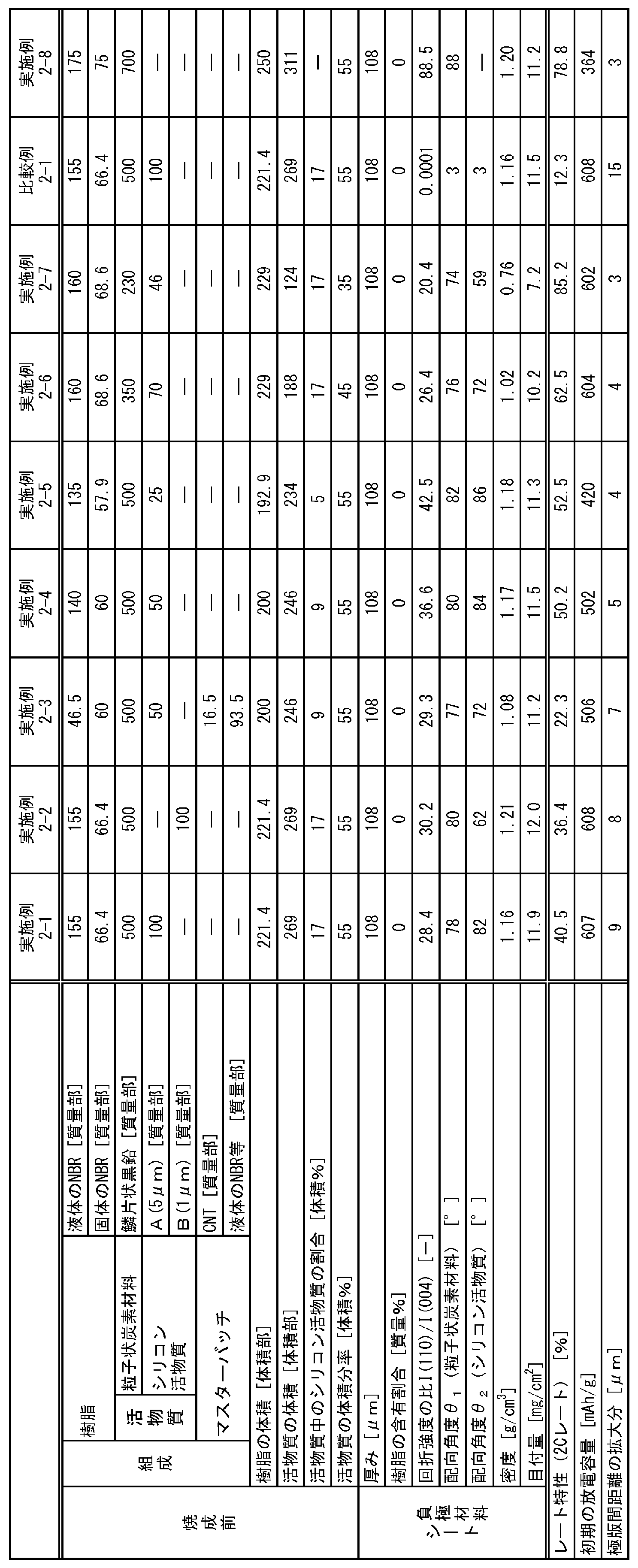
一方、主面のX線回折における回折強度の比I(110)/I(004)が所定値に満たない比較例2-1の負極材料シートを備える負極を用いた二次電池は、レート特性に劣ることが分かる。
また、本発明によれば、非水系二次電池に優れたレート特性を発揮させ得る負極を提供することができる。
さらに、本発明によれば、優れたレート特性を発揮し得る非水系二次電池を提供することができる。
Claims (18)
- 粒子状炭素材料を含む非水系二次電池用負極材料シートであって、
前記非水系二次電池用負極材料シートの主面のX線回折における(004)面の回折強度に対する(110)面の回折強度の比I(110)/I(004)が、1.1以上であり、
下記(1)および(2)の少なくとも一方を満たす、非水系二次電池用負極材料シート。
(1)前記非水系二次電池用負極材料シート中の樹脂の含有割合が8質量%以下である。
(2)前記非水系二次電池用負極材料シートの密度が1.3g/cm3以下である。 - 厚みが80μm以上である、請求項1に記載の非水系二次電池用負極材料シート。
- 前記粒子状炭素材料が鱗片状黒鉛を含む、請求項1または2に記載の非水系二次電池用負極材料シート。
- 前記粒子状炭素材料のアスペクト比が1.2超20以下である、請求項1~3のいずれかに記載の非水系二次電池用負極材料シート。
- 前記比I(110)/I(004)が20以上である、請求項1~4のいずれかに記載の非水系二次電池用負極材料シート。
- 前記樹脂の含有割合が3質量%以下である、請求項1~5のいずれかに記載の非水系二次電池用負極材料シート。
- 厚み方向断面視において、前記非水系二次電池用負極材料シートの主面に対する前記粒子状炭素材料の配向角度θ1が60°以上90°以下である、請求項1~6のいずれかに記載の非水系二次電池用負極材料シート。
- シリコン活物質を更に含み、
厚み方向断面視において、前記非水系二次電池用負極材料シートの主面に対する前記粒子状炭素材料の配向角度θ1が45°以上90°以下であり、前記非水系二次電池用負極材料シートの主面に対する前記シリコン活物質の配向角度θ2が45°以上90°以下である、請求項1~6のいずれかに記載の非水系二次電池用負極材料シート。 - 前記シリコン活物質の体積が、前記粒子状炭素材料および前記シリコン活物質の合計体積に対して、5体積%以上30体積%以下である、請求項8に記載の非水系二次電池用負極材料シート。
- 前記非水系二次電池用負極材料シートの全質量に占める繊維状炭素材料の質量の割合が1質量%以下である、請求項1~9のいずれかに記載の非水系二次電池用負極材料シート。
- 樹脂と粒子状炭素材料とを含む組成物を加圧してシート状に成形し、1次シートを得る1次シート成形工程と、
前記1次シートを厚み方向に複数枚積層して、或いは、前記1次シートを折畳または捲回して、積層体を得る積層体形成工程と、
前記積層体を積層方向に対して45°以下の角度でスライスして、2次シートを得るスライス工程と、
前記2次シートを焼成する焼成工程と、を含む非水系二次電池用負極材料シートの製造方法。 - 前記樹脂の分解開始温度をT℃として、
前記焼成工程において前記2次シートをT-50℃以上で焼成する、請求項11に記載の非水系二次電池用負極材料シートの製造方法。 - 前記焼成工程において前記2次シートを300℃以上2000℃以下で焼成する、請求項11または12に記載の非水系二次電池用負極材料シートの製造方法。
- 前記粒子状炭素材料が鱗片状黒鉛を含む、請求項11~13のいずれかに記載の非水系二次電池用負極材料シートの製造方法。
- 前記粒子状炭素材料のアスペクト比が2超20以下である、請求項11~14のいずれかに記載の非水系二次電池用負極材料シートの製造方法。
- 前記組成物がシリコン活物質を更に含む、請求項11~15のいずれかに記載の非水系二次電池用負極材料シートの製造方法。
- 請求項1~10のいずれかに記載の非水系二次電池用負極材料シートを備える非水系二次電池用負極。
- 請求項17に記載の非水系二次電池用負極を備える非水系二次電池。
Priority Applications (4)
| Application Number | Priority Date | Filing Date | Title |
|---|---|---|---|
| US18/249,542 US20230387385A1 (en) | 2020-11-13 | 2021-11-11 | Negative electrode material sheet for non-aqueous secondary battery, method of producing same, negative electrode for non-aqueous secondary battery, and non-aqueous secondary battery |
| CN202180074972.3A CN116391272A (zh) | 2020-11-13 | 2021-11-11 | 非水系二次电池用负极材料片及其制造方法、非水系二次电池用负极、以及非水系二次电池 |
| JP2022562186A JPWO2022102724A1 (ja) | 2020-11-13 | 2021-11-11 | |
| EP21891969.4A EP4246614A4 (en) | 2020-11-13 | 2021-11-11 | NEGATIVE ELECTRODE MATERIAL SHEET FOR NONAQUEOUS SECONDARY BATTERY, METHOD FOR MANUFACTURING SAME, NEGATIVE ELECTRODE FOR NONAQUEOUS SECONDARY BATTERY, AND NONAQUEOUS SECONDARY BATTERY |
Applications Claiming Priority (4)
| Application Number | Priority Date | Filing Date | Title |
|---|---|---|---|
| JP2020-189808 | 2020-11-13 | ||
| JP2020189808 | 2020-11-13 | ||
| JP2021099053 | 2021-06-14 | ||
| JP2021-099053 | 2021-06-14 |
Publications (1)
| Publication Number | Publication Date |
|---|---|
| WO2022102724A1 true WO2022102724A1 (ja) | 2022-05-19 |
Family
ID=81601280
Family Applications (1)
| Application Number | Title | Priority Date | Filing Date |
|---|---|---|---|
| PCT/JP2021/041609 Ceased WO2022102724A1 (ja) | 2020-11-13 | 2021-11-11 | 非水系二次電池用負極材料シートおよびその製造方法、非水系二次電池用負極、並びに、非水系二次電池 |
Country Status (5)
| Country | Link |
|---|---|
| US (1) | US20230387385A1 (ja) |
| EP (1) | EP4246614A4 (ja) |
| JP (1) | JPWO2022102724A1 (ja) |
| CN (1) | CN116391272A (ja) |
| WO (1) | WO2022102724A1 (ja) |
Cited By (1)
| Publication number | Priority date | Publication date | Assignee | Title |
|---|---|---|---|---|
| JP2025511597A (ja) * | 2022-12-07 | 2025-04-16 | エルジー エナジー ソリューション リミテッド | リチウム二次電池用負極およびその製造方法 |
Citations (7)
| Publication number | Priority date | Publication date | Assignee | Title |
|---|---|---|---|---|
| WO2006011655A1 (ja) | 2004-07-27 | 2006-02-02 | National Institute Of Advanced Industrial Scienceand Technology | 単層カーボンナノチューブおよび配向単層カーボンナノチューブ・バルク構造体ならびにそれらの製造方法・装置および用途 |
| WO2012039041A1 (ja) * | 2010-09-22 | 2012-03-29 | トヨタ自動車株式会社 | 非水電解質二次電池 |
| JP2012204303A (ja) | 2011-03-28 | 2012-10-22 | Nippon Zeon Co Ltd | 二次電池用電極、二次電池電極用バインダー、製造方法及び二次電池 |
| WO2013018180A1 (ja) * | 2011-07-29 | 2013-02-07 | トヨタ自動車株式会社 | リチウムイオン二次電池 |
| JP2017016773A (ja) * | 2015-06-29 | 2017-01-19 | 新日鉄住金化学株式会社 | リチウムイオン二次電池負極及び二次電池 |
| JP2018129212A (ja) * | 2017-02-09 | 2018-08-16 | トヨタ自動車株式会社 | 二次電池用の負極 |
| JP2020184472A (ja) * | 2019-05-09 | 2020-11-12 | 株式会社Gsユアサ | 非水電解質蓄電素子用正極、及びこれを備えた非水電解質蓄電素子 |
Family Cites Families (2)
| Publication number | Priority date | Publication date | Assignee | Title |
|---|---|---|---|---|
| WO2013067280A1 (en) * | 2011-11-04 | 2013-05-10 | Carben Semicon Limited | Carbon film and method of production thereof |
| KR102778726B1 (ko) * | 2018-03-15 | 2025-03-12 | 에스케이온 주식회사 | 이차전지용 전극 및 이의 제조방법 |
-
2021
- 2021-11-11 EP EP21891969.4A patent/EP4246614A4/en active Pending
- 2021-11-11 JP JP2022562186A patent/JPWO2022102724A1/ja active Pending
- 2021-11-11 US US18/249,542 patent/US20230387385A1/en active Pending
- 2021-11-11 CN CN202180074972.3A patent/CN116391272A/zh active Pending
- 2021-11-11 WO PCT/JP2021/041609 patent/WO2022102724A1/ja not_active Ceased
Patent Citations (7)
| Publication number | Priority date | Publication date | Assignee | Title |
|---|---|---|---|---|
| WO2006011655A1 (ja) | 2004-07-27 | 2006-02-02 | National Institute Of Advanced Industrial Scienceand Technology | 単層カーボンナノチューブおよび配向単層カーボンナノチューブ・バルク構造体ならびにそれらの製造方法・装置および用途 |
| WO2012039041A1 (ja) * | 2010-09-22 | 2012-03-29 | トヨタ自動車株式会社 | 非水電解質二次電池 |
| JP2012204303A (ja) | 2011-03-28 | 2012-10-22 | Nippon Zeon Co Ltd | 二次電池用電極、二次電池電極用バインダー、製造方法及び二次電池 |
| WO2013018180A1 (ja) * | 2011-07-29 | 2013-02-07 | トヨタ自動車株式会社 | リチウムイオン二次電池 |
| JP2017016773A (ja) * | 2015-06-29 | 2017-01-19 | 新日鉄住金化学株式会社 | リチウムイオン二次電池負極及び二次電池 |
| JP2018129212A (ja) * | 2017-02-09 | 2018-08-16 | トヨタ自動車株式会社 | 二次電池用の負極 |
| JP2020184472A (ja) * | 2019-05-09 | 2020-11-12 | 株式会社Gsユアサ | 非水電解質蓄電素子用正極、及びこれを備えた非水電解質蓄電素子 |
Non-Patent Citations (1)
| Title |
|---|
| See also references of EP4246614A4 |
Cited By (4)
| Publication number | Priority date | Publication date | Assignee | Title |
|---|---|---|---|---|
| JP2025511597A (ja) * | 2022-12-07 | 2025-04-16 | エルジー エナジー ソリューション リミテッド | リチウム二次電池用負極およびその製造方法 |
| EP4478446A4 (en) * | 2022-12-07 | 2025-05-21 | LG Energy Solution, Ltd. | NEGATIVE ELECTRODE FOR LITHIUM SECONDARY BATTERY AND METHOD FOR MANUFACTURING SAME |
| US12438182B2 (en) | 2022-12-07 | 2025-10-07 | Lg Energy Solution, Ltd. | Negative electrode for lithium secondary battery, and method for manufacturing same |
| JP7827373B2 (ja) | 2022-12-07 | 2026-03-10 | エルジー エナジー ソリューション リミテッド | リチウム二次電池用負極およびその製造方法 |
Also Published As
| Publication number | Publication date |
|---|---|
| EP4246614A1 (en) | 2023-09-20 |
| JPWO2022102724A1 (ja) | 2022-05-19 |
| CN116391272A (zh) | 2023-07-04 |
| EP4246614A4 (en) | 2025-09-10 |
| US20230387385A1 (en) | 2023-11-30 |
Similar Documents
| Publication | Publication Date | Title |
|---|---|---|
| JP7269511B2 (ja) | 非水系電解液を使用する二次電池用電極の製造方法及び非水系電解液を使用する二次電池電極用結着剤 | |
| KR102919650B1 (ko) | 단층 카본 나노튜브와 ptfe를 복합한 결착제, 그리고 그것을 사용한 전극 제작용 조성물 및 이차 전지 | |
| WO2022138942A1 (ja) | 固体二次電池用シートの製造方法及び固体二次電池用結着剤 | |
| KR102941160B1 (ko) | 이차 전지용 전극 합제, 이차 전지용 전극 합제 시트 및 그 제조 방법 그리고 이차 전지 | |
| JP2013506266A (ja) | 電極活物質である遷移金属化合物と繊維状炭素材料とを含有する複合体及びその製造方法 | |
| TWI594945B (zh) | Metal tin-carbon composite, use thereof, negative electrode active material for non-aqueous lithium battery using the same, negative electrode containing non-aqueous lithium-ion battery and non-aqueous lithium secondary battery | |
| JP2009038023A (ja) | 電気化学的蓄電デバイス用電極 | |
| EP2299525A1 (en) | Nonaqueous electrolyte secondary battery | |
| JP7789898B2 (ja) | 導電材マスターバッチ及びこれを用いて製造された乾式電極 | |
| WO2022102724A1 (ja) | 非水系二次電池用負極材料シートおよびその製造方法、非水系二次電池用負極、並びに、非水系二次電池 | |
| WO2023167296A1 (ja) | 二次電池用合剤、二次電池用合剤シート、二次電池用合剤シートの製造方法及び二次電池 | |
| JP7819459B2 (ja) | 非水系二次電池用負極材料シートおよびその製造方法、非水系二次電池用負極、並びに、非水系二次電池 | |
| JP7477784B2 (ja) | 非水系電解液を使用する二次電池用電極の製造方法、非水系電解液を使用する二次電池電極用結着剤、二次電池電極用結着剤、電極作製用組成物、電極合剤及び電極 | |
| JP7714923B2 (ja) | 非水系二次電池用負極材料シート、非水系二次電池用負極、及び非水系二次電池、並びに非水系二次電池用負極材料シートの製造方法 | |
| JP5708198B2 (ja) | 二次電池用炭素材及びその製造方法 | |
| JP7760773B1 (ja) | カーボンナノチューブ集合体、カーボンナノチューブ分散液、導電材料、電極、二次電池、平面状集合体、及び組成物 | |
| JP7599599B1 (ja) | 導電助剤、分散液、電極、二次電池、多層カーボンナノチューブ粉末、平面状集合体、フィルター、電磁波シールド及び極端紫外線用ペリクル | |
| JP2023169050A (ja) | 非水系二次電池用負極材料シートおよびその製造方法、非水系二次電池用負極およびその製造方法、並びに、非水系二次電池 | |
| JP2023149190A (ja) | 非水系二次電池用負極の製造方法、非水系二次電池用負極、および非水系二次電池 | |
| WO2024004871A1 (ja) | 固体二次電池用シートの製造方法、固体二次電池電極用結着剤、電極作製用組成物、電極合剤、及び、電極 | |
| KR20240153360A (ko) | 이차 전지용 합제, 이차 전지용 합제 시트 및 그 제조 방법 그리고 고체 이차 전지 | |
| JP2026074267A (ja) | 非水系電解液を使用する二次電池電極用結着剤、電極作製用組成物、電極合剤、電極、及びリチウムイオン二次電池 | |
| WO2026071262A1 (ja) | 準固体電池の製造方法 | |
| JP2015122316A (ja) | 二次電池用炭素材及びその製造方法 |
Legal Events
| Date | Code | Title | Description |
|---|---|---|---|
| 121 | Ep: the epo has been informed by wipo that ep was designated in this application |
Ref document number: 21891969 Country of ref document: EP Kind code of ref document: A1 |
|
| ENP | Entry into the national phase |
Ref document number: 2022562186 Country of ref document: JP Kind code of ref document: A |
|
| WWE | Wipo information: entry into national phase |
Ref document number: 18249542 Country of ref document: US |
|
| NENP | Non-entry into the national phase |
Ref country code: DE |
|
| ENP | Entry into the national phase |
Ref document number: 2021891969 Country of ref document: EP Effective date: 20230613 |