WO2022107861A1 - 前駆体、リチウム二次電池用正極活物質、リチウム二次電池用正極及びリチウム二次電池 - Google Patents
前駆体、リチウム二次電池用正極活物質、リチウム二次電池用正極及びリチウム二次電池 Download PDFInfo
- Publication number
- WO2022107861A1 WO2022107861A1 PCT/JP2021/042492 JP2021042492W WO2022107861A1 WO 2022107861 A1 WO2022107861 A1 WO 2022107861A1 JP 2021042492 W JP2021042492 W JP 2021042492W WO 2022107861 A1 WO2022107861 A1 WO 2022107861A1
- Authority
- WO
- WIPO (PCT)
- Prior art keywords
- less
- secondary battery
- positive electrode
- lithium secondary
- precursor
- Prior art date
- Legal status (The legal status is an assumption and is not a legal conclusion. Google has not performed a legal analysis and makes no representation as to the accuracy of the status listed.)
- Ceased
Links
Images


Classifications
-
- C—CHEMISTRY; METALLURGY
- C01—INORGANIC CHEMISTRY
- C01G—COMPOUNDS CONTAINING METALS NOT COVERED BY SUBCLASSES C01D OR C01F
- C01G53/00—Compounds of nickel
- C01G53/40—Complex oxides containing nickel and at least one other metal element
- C01G53/42—Complex oxides containing nickel and at least one other metal element containing alkali metals, e.g. LiNiO2
- C01G53/44—Complex oxides containing nickel and at least one other metal element containing alkali metals, e.g. LiNiO2 containing manganese
- C01G53/50—Complex oxides containing nickel and at least one other metal element containing alkali metals, e.g. LiNiO2 containing manganese of the type (MnO2)n-, e.g. Li(NixMn1-x)O2 or Li(MyNixMn1-x-y)O2
-
- C—CHEMISTRY; METALLURGY
- C01—INORGANIC CHEMISTRY
- C01G—COMPOUNDS CONTAINING METALS NOT COVERED BY SUBCLASSES C01D OR C01F
- C01G53/00—Compounds of nickel
- C01G53/80—Compounds containing nickel, with or without oxygen or hydrogen, and containing one or more other elements
- C01G53/82—Compounds containing nickel, with or without oxygen or hydrogen, and containing two or more other elements
-
- H—ELECTRICITY
- H01—ELECTRIC ELEMENTS
- H01M—PROCESSES OR MEANS, e.g. BATTERIES, FOR THE DIRECT CONVERSION OF CHEMICAL ENERGY INTO ELECTRICAL ENERGY
- H01M10/00—Secondary cells; Manufacture thereof
- H01M10/05—Accumulators with non-aqueous electrolyte
- H01M10/052—Li-accumulators
-
- H—ELECTRICITY
- H01—ELECTRIC ELEMENTS
- H01M—PROCESSES OR MEANS, e.g. BATTERIES, FOR THE DIRECT CONVERSION OF CHEMICAL ENERGY INTO ELECTRICAL ENERGY
- H01M4/00—Electrodes
- H01M4/02—Electrodes composed of, or comprising, active material
- H01M4/13—Electrodes for accumulators with non-aqueous electrolyte, e.g. for lithium-accumulators; Processes of manufacture thereof
- H01M4/131—Electrodes based on mixed oxides or hydroxides, or on mixtures of oxides or hydroxides, e.g. LiCoOx
-
- H—ELECTRICITY
- H01—ELECTRIC ELEMENTS
- H01M—PROCESSES OR MEANS, e.g. BATTERIES, FOR THE DIRECT CONVERSION OF CHEMICAL ENERGY INTO ELECTRICAL ENERGY
- H01M4/00—Electrodes
- H01M4/02—Electrodes composed of, or comprising, active material
- H01M4/36—Selection of substances as active materials, active masses, active liquids
- H01M4/48—Selection of substances as active materials, active masses, active liquids of inorganic oxides or hydroxides
- H01M4/50—Selection of substances as active materials, active masses, active liquids of inorganic oxides or hydroxides of manganese
- H01M4/505—Selection of substances as active materials, active masses, active liquids of inorganic oxides or hydroxides of manganese of mixed oxides or hydroxides containing manganese for inserting or intercalating light metals, e.g. LiMn2O4 or LiMn2OxFy
-
- H—ELECTRICITY
- H01—ELECTRIC ELEMENTS
- H01M—PROCESSES OR MEANS, e.g. BATTERIES, FOR THE DIRECT CONVERSION OF CHEMICAL ENERGY INTO ELECTRICAL ENERGY
- H01M4/00—Electrodes
- H01M4/02—Electrodes composed of, or comprising, active material
- H01M4/36—Selection of substances as active materials, active masses, active liquids
- H01M4/48—Selection of substances as active materials, active masses, active liquids of inorganic oxides or hydroxides
- H01M4/52—Selection of substances as active materials, active masses, active liquids of inorganic oxides or hydroxides of nickel, cobalt or iron
- H01M4/525—Selection of substances as active materials, active masses, active liquids of inorganic oxides or hydroxides of nickel, cobalt or iron of mixed oxides or hydroxides containing iron, cobalt or nickel for inserting or intercalating light metals, e.g. LiNiO2, LiCoO2 or LiCoOxFy
-
- C—CHEMISTRY; METALLURGY
- C01—INORGANIC CHEMISTRY
- C01P—INDEXING SCHEME RELATING TO STRUCTURAL AND PHYSICAL ASPECTS OF SOLID INORGANIC COMPOUNDS
- C01P2002/00—Crystal-structural characteristics
- C01P2002/50—Solid solutions
- C01P2002/52—Solid solutions containing elements as dopants
-
- C—CHEMISTRY; METALLURGY
- C01—INORGANIC CHEMISTRY
- C01P—INDEXING SCHEME RELATING TO STRUCTURAL AND PHYSICAL ASPECTS OF SOLID INORGANIC COMPOUNDS
- C01P2002/00—Crystal-structural characteristics
- C01P2002/50—Solid solutions
- C01P2002/52—Solid solutions containing elements as dopants
- C01P2002/54—Solid solutions containing elements as dopants one element only
-
- C—CHEMISTRY; METALLURGY
- C01—INORGANIC CHEMISTRY
- C01P—INDEXING SCHEME RELATING TO STRUCTURAL AND PHYSICAL ASPECTS OF SOLID INORGANIC COMPOUNDS
- C01P2002/00—Crystal-structural characteristics
- C01P2002/70—Crystal-structural characteristics defined by measured X-ray, neutron or electron diffraction data
- C01P2002/76—Crystal-structural characteristics defined by measured X-ray, neutron or electron diffraction data by a space-group or by other symmetry indications
-
- C—CHEMISTRY; METALLURGY
- C01—INORGANIC CHEMISTRY
- C01P—INDEXING SCHEME RELATING TO STRUCTURAL AND PHYSICAL ASPECTS OF SOLID INORGANIC COMPOUNDS
- C01P2004/00—Particle morphology
- C01P2004/30—Particle morphology extending in three dimensions
- C01P2004/45—Aggregated particles or particles with an intergrown morphology
-
- C—CHEMISTRY; METALLURGY
- C01—INORGANIC CHEMISTRY
- C01P—INDEXING SCHEME RELATING TO STRUCTURAL AND PHYSICAL ASPECTS OF SOLID INORGANIC COMPOUNDS
- C01P2006/00—Physical properties of inorganic compounds
- C01P2006/11—Powder tap density
-
- C—CHEMISTRY; METALLURGY
- C01—INORGANIC CHEMISTRY
- C01P—INDEXING SCHEME RELATING TO STRUCTURAL AND PHYSICAL ASPECTS OF SOLID INORGANIC COMPOUNDS
- C01P2006/00—Physical properties of inorganic compounds
- C01P2006/12—Surface area
-
- C—CHEMISTRY; METALLURGY
- C01—INORGANIC CHEMISTRY
- C01P—INDEXING SCHEME RELATING TO STRUCTURAL AND PHYSICAL ASPECTS OF SOLID INORGANIC COMPOUNDS
- C01P2006/00—Physical properties of inorganic compounds
- C01P2006/14—Pore volume
-
- C—CHEMISTRY; METALLURGY
- C01—INORGANIC CHEMISTRY
- C01P—INDEXING SCHEME RELATING TO STRUCTURAL AND PHYSICAL ASPECTS OF SOLID INORGANIC COMPOUNDS
- C01P2006/00—Physical properties of inorganic compounds
- C01P2006/16—Pore diameter
-
- C—CHEMISTRY; METALLURGY
- C01—INORGANIC CHEMISTRY
- C01P—INDEXING SCHEME RELATING TO STRUCTURAL AND PHYSICAL ASPECTS OF SOLID INORGANIC COMPOUNDS
- C01P2006/00—Physical properties of inorganic compounds
- C01P2006/40—Electric properties
-
- H—ELECTRICITY
- H01—ELECTRIC ELEMENTS
- H01M—PROCESSES OR MEANS, e.g. BATTERIES, FOR THE DIRECT CONVERSION OF CHEMICAL ENERGY INTO ELECTRICAL ENERGY
- H01M4/00—Electrodes
- H01M4/02—Electrodes composed of, or comprising, active material
- H01M2004/021—Physical characteristics, e.g. porosity, surface area
-
- H—ELECTRICITY
- H01—ELECTRIC ELEMENTS
- H01M—PROCESSES OR MEANS, e.g. BATTERIES, FOR THE DIRECT CONVERSION OF CHEMICAL ENERGY INTO ELECTRICAL ENERGY
- H01M4/00—Electrodes
- H01M4/02—Electrodes composed of, or comprising, active material
- H01M2004/026—Electrodes composed of, or comprising, active material characterised by the polarity
- H01M2004/028—Positive electrodes
-
- Y—GENERAL TAGGING OF NEW TECHNOLOGICAL DEVELOPMENTS; GENERAL TAGGING OF CROSS-SECTIONAL TECHNOLOGIES SPANNING OVER SEVERAL SECTIONS OF THE IPC; TECHNICAL SUBJECTS COVERED BY FORMER USPC CROSS-REFERENCE ART COLLECTIONS [XRACs] AND DIGESTS
- Y02—TECHNOLOGIES OR APPLICATIONS FOR MITIGATION OR ADAPTATION AGAINST CLIMATE CHANGE
- Y02E—REDUCTION OF GREENHOUSE GAS [GHG] EMISSIONS, RELATED TO ENERGY GENERATION, TRANSMISSION OR DISTRIBUTION
- Y02E60/00—Enabling technologies; Technologies with a potential or indirect contribution to GHG emissions mitigation
- Y02E60/10—Energy storage using batteries
Definitions
- the present invention relates to a precursor, a positive electrode active material for a lithium secondary battery, a positive electrode for a lithium secondary battery, and a lithium secondary battery.
- a method for producing a positive electrode active material for a lithium secondary battery for example, there is a method in which a lithium compound and a precursor containing an element other than lithium are mixed and fired.
- elements other than lithium include nickel, cobalt, and manganese.
- Patent Document 1 discloses a technique focusing on the pores of a nickel-cobalt-manganese composite hydroxide which is a precursor of a positive electrode active material of a non-aqueous electrolyte secondary battery. is doing. Specifically, in Patent Document 1, nickel having an average mesopore radius measured by a nitrogen adsorption method of 4.00 to 6.00 nm and a pore volume of 0.010 to 0.020 ml / g. Cobalt-manganese composite hydroxides are described.
- Patent Document 2 describes a lithium ion secondary battery in which the pore curvature of the positive electrode active material layer is 50 or more and 120 or less.
- the lithium ion secondary battery described in Patent Document 2 can sufficiently suppress an increase in the resistance of the secondary battery in a low temperature (for example, ⁇ 20 ° C.) environment.
- Lithium secondary batteries which are expected to spread rapidly in the future, are required to have a high discharge capacity and are not easily deteriorated when stored at a high temperature.
- the present invention has been made in view of the above circumstances, and it is an object of the present invention to provide a lithium secondary battery having a high discharge capacity and not easily deteriorated during high temperature storage, and to provide a precursor which is a raw material of a positive electrode active material. And. Further, it is an object of the present invention to provide a positive electrode active material for a lithium secondary battery, a positive electrode for a lithium secondary battery, and a lithium secondary battery using the same.
- a precursor of a positive electrode active material for a lithium secondary battery which contains at least Ni and has a value ⁇ calculated from the following formula (1) of 2.3 m / ng or less.
- ⁇ A 2 / (4 ⁇ V) ⁇ 1000 ⁇ ⁇ ⁇ (1)
- A has a pore diameter of 2.6 nm or more among the pore specific surface areas obtained by analyzing the nitrogen desorption isotherm of the precursor measured at the liquid nitrogen temperature by the BJH method. Cumulative pore specific surface area (m 2 / g) of 200 nm or less.
- V is the cumulative pore volume having a pore diameter of 2.6 nm or more and 200 nm or less among the pore volumes obtained by analyzing the nitrogen desorption isotherm of the precursor measured at the liquid nitrogen temperature by the BJH method (the cumulative pore volume is 2.6 nm or more and 200 nm or less. cm 3 / g).
- [2] The precursor according to [1], wherein the value ⁇ calculated from the following formula (2) is 2.8 m / ng or less.
- B has a pore diameter of 2.6 nm or more among the pore specific surface areas obtained by analyzing the nitrogen desorption isotherm of the precursor measured at the liquid nitrogen temperature by the BJH method. Cumulative pore specific surface area (m 2 / g) of 50 nm or less.
- X is a cumulative pore volume having a pore diameter of 2.6 nm or more and 50 nm or less among the pore volumes obtained by analyzing the nitrogen desorption isotherm of the precursor measured at the liquid nitrogen temperature by the BJH method. cm 3 / g).
- [3] The precursor according to [1] or [2], which has a BET specific surface area of 1.0 m 2 / g or more and 25 m 2 / g or less. [4] The precursor according to any one of [1] to [3], wherein the tap density is 0.8 g / cm 3 or more and 2.7 g / cm 3 or less. [5] A positive electrode active material for a lithium secondary battery containing at least Ni and having a value ⁇ calculated from the following formula (3) of 4.0 m / ⁇ g or more and 40.0 m / ⁇ g or less.
- C is a pore among the pore specific surface areas obtained by analyzing the nitrogen desorption isotherm of the positive electrode active material for a lithium secondary battery measured at a liquid nitrogen temperature by the BJH method.
- Cumulative pore specific surface area (m 2 / g) having a diameter of 2.6 nm or more and 200 nm or less.
- Y has a pore diameter of 2.6 nm or more and 200 nm or less among the pore volumes obtained by analyzing the nitrogen desorption isotherm of the positive electrode active material for a lithium secondary battery measured at a liquid nitrogen temperature by the BJH method.
- the positive electrode active material for a lithium secondary battery according to [5] or [6] represented by the following composition formula (I). Li [Li a (Ni 1-x-y Co x My) 1-a ] O 2 ...
- M is at least one selected from the group consisting of Fe, Cu, Mg, Mn, Al, W, B, Mo, Zn, Sn, Zr, Ga, La, Ti, Nb and V. It is a seed element and satisfies ⁇ 0.10 ⁇ a ⁇ 0.30, 0 ⁇ x ⁇ 0.45, and 0 ⁇ y ⁇ 0.45).
- the positive electrode active material for a lithium secondary battery according to any one of [5] to [7], wherein the BET specific surface area is 0.3 m 2 / g or more and 4.0 m 2 / g or less.
- the present invention it is possible to provide a lithium secondary battery having a high discharge capacity and not easily deteriorated at high temperature storage, and to provide a precursor which is a raw material of a positive electrode active material. Further, it is possible to provide a positive electrode active material for a lithium secondary battery, a positive electrode for a lithium secondary battery, and a lithium secondary battery using the same.
- FIG. 2 is a schematic view showing a laminate included in an all-solid-state lithium secondary battery.
- FIG. 3 is a schematic diagram showing the overall configuration of the all-solid-state lithium secondary battery.
- the positive electrode active material for a lithium secondary battery of the present embodiment may be referred to as a “positive electrode active material”.
- the cathode active material (Cathode Active Material for lithium secondary batteries) for a lithium secondary battery is hereinafter referred to as “CAM”.
- the high discharge capacity and the degree of deterioration during high temperature storage are evaluated by the following methods.
- [High temperature storage test] Using a lithium secondary battery, a current set value of 0.2 CA is set at a test temperature of 25 ° C., and constant current constant voltage charging and constant current discharging are performed, respectively. The maximum charge voltage is 4.3 V, and the minimum discharge voltage is 2.5 V. The discharge capacity is measured, and the obtained value is defined as the "discharge capacity before storage". When the discharge capacity before storage is 180 mAh / g or more, it is evaluated as “high discharge capacity”.
- the lithium secondary battery after measuring the discharge capacity before storage is charged again to 4.3 V with a constant current and constant voltage at a current set value of 0.2 CA.
- the discharge capacity is measured by constant current discharge at a test temperature of 25 ° C. at a current set value of 0.2 CA. This discharge capacity is referred to as "discharge capacity after storage”.
- discharge capacity after storage From the discharge capacity before storage and the discharge capacity after storage, the storage capacity retention rate before and after high-temperature storage is calculated. When the storage capacity retention rate is 85% or more, it is evaluated as "hard to deteriorate during high temperature storage”.
- composition analysis of the precursor and the CAM can be measured by dissolving the precursor and the CAM powder in hydrochloric acid, respectively, and then using an ICP emission spectrophotometer.
- ICP emission spectroscopic analyzer for example, Optima 7300 manufactured by PerkinElmer Co., Ltd. can be used.
- the BET specific surface area of the precursor or CAM can be measured by a BET specific surface area measuring device. Specifically, for example, 1 g of the precursor or CAM powder may be dried in a nitrogen atmosphere at 105 ° C. for 30 minutes, and then measured using Macsorb (registered trademark) manufactured by Mountech (unit: m 2 ). / G).
- This embodiment is a precursor of CAM.
- the precursor contains at least Ni.
- the precursor is a raw material for CAM.
- the term "precursor” when used, it means the precursor of the present embodiment.
- preferred examples and conditions may be shared in a plurality of embodiments and numerical ranges.
- Ni refers not to a nickel metal but a nickel atom
- Co, Mn, Li and the like also refer to a cobalt atom, a manganese atom, a lithium atom and the like, respectively.
- the precursor is composed of primary particles and secondary particles which are aggregates of primary particles. In one embodiment of the present embodiment, the precursor is a powder. In one embodiment of the present embodiment, the precursor comprises at least Ni.
- the precursor has a value ⁇ calculated from the following formula (1) of 2.3 m / ng or less.
- ⁇ A 2 / (4 ⁇ V) ⁇ 1000 ⁇ ⁇ ⁇ (1)
- A has a pore diameter of 2.6 nm or more and 200 nm among the pore specific surface areas obtained by analyzing the nitrogen desorption isotherm of the precursor measured at the liquid nitrogen temperature by the BJH method.
- V is the cumulative pore volume (cm) having a pore diameter of 2.6 nm or more and 200 nm or less among the pore volumes obtained by analyzing the nitrogen desorption isotherm of the precursor measured at the liquid nitrogen temperature by the BJH method. 3 / g). )
- the precursor is evacuated at 80 ° C. for 8 hours using a vacuum heat treatment apparatus.
- a vacuum heat treatment apparatus for example, BELSORP-vacII manufactured by Microtrac Bell Co., Ltd. can be used.
- the nitrogen desorption isotherm and the nitrogen adsorption isotherm at the liquid nitrogen temperature (77K) are measured for the precursor.
- nitrogen is gradually added from the start state under vacuum, and the amount of nitrogen adsorbed is calculated by the constant volume method from the pressure change of nitrogen due to adsorption.
- an adsorption isotherm of nitrogen from 0 atm to 1 atm at the liquid nitrogen temperature is obtained.
- nitrogen is gradually reduced to obtain desorption isotherms from 1 atm to 0 atm.
- the nitrogen adsorption isotherm device and the nitrogen desorption isotherm measuring device for example, BELSORP-mini manufactured by Microtrac Bell Co., Ltd. can be used.
- Nitrogen Adsorption The amount of nitrogen adsorbed per unit weight of the precursor in the isotherm is calculated to be represented by the volume of gaseous nitrogen in the standard state (STP; Standard Temperature and Pressure). The amount of nitrogen desorbed per unit weight of the precursor in the desorption isotherm is calculated to be represented by the volume of gaseous nitrogen in the standard state (STP; Standard Temperature and Pressure).
- the obtained nitrogen desorption isotherm is analyzed by the BJH method (Barrett-Joiner-Halenda method).
- the BJH method is a method of calculating the pore diameter distribution using a cylindrical pore as a model.
- the diameter D of the cylinder is 4 L / S.
- the "pore specific surface area” means the surface area of only the side surface of the cylindrical pore per unit mass.
- the height (that is, the length of the pores) h of the cylinder is determined by the following formula (that is, the pore length) h from the pore volume L (cm 3 / g) and the pore specific surface area S (cm 2 / g). It can be calculated by H).
- h S 2 / 4 ⁇ L ⁇ ⁇ ⁇ (H)
- ⁇ is 2.3 m / ng or less, preferably 2.0 m / ng or less, and more preferably 1.8 m / ng or less.
- ⁇ is equal to or less than the above upper limit value, it means that the model has a simple pore path in the model assuming that the pores are cylindrical.
- a precursor whose ⁇ is equal to or less than the above upper limit value that is, a precursor having a relatively short pore length per unit mass
- the simple pore path means a pore path that does not have a complexly branched pore path inside the particle.
- a CAM made from a precursor whose ⁇ is equal to or less than the above upper limit tends to maintain the same simple pore pathway as the precursor.
- a lithium secondary battery using a CAM made from a precursor whose ⁇ is equal to or less than the above upper limit has a high discharge capacity and is unlikely to deteriorate during high-temperature storage.
- Examples of the lower limit of ⁇ include 0.1 m / ng or more, 0.2 m / ng or more, and 0.3 m / ng or more.
- the above upper limit value and lower limit value of ⁇ can be arbitrarily combined. Examples of combinations include ⁇ of 0.1 m / ng or more and 2.3 m / ng or less, 0.2 m / ng or more and 2.0 m / ng or less, and 0.3 m / ng or more and 1.8 m / ng or less. ..
- the precursor whose ⁇ is equal to or higher than the above lower limit has an appropriate pore path inside the particles. It is considered that the CAM using such a precursor as a raw material has an appropriate pore path inside the particles. It is considered that the lithium secondary battery using such a CAM has a high discharge capacity. The reason is that the diffusion distance of lithium ions in the particles of the CAM is shorter in the CAM having the pore pathway than in the CAM having no pore pathway.
- A is preferably 5 m 2 / g or more and 55 m 2 / g or less, and more preferably 10 m 2 / g or more and 50 m 2 / g or less.
- V is preferably 0.010 cm 3 / g or more and 0.11 cm 3 / g or less, and more preferably 0.015 cm 3 / g or more and 0.10 cm 3 / g or less.
- the precursor has a value ⁇ calculated from the following formula (2) of 2.8 m / ng or less.
- ⁇ B 2 / (4 ⁇ X) ⁇ 1000 ⁇ ⁇ ⁇ (2)
- B is a pore diameter of 2.6 nm or more and 50 nm or less among the pore specific surface areas obtained by analyzing the nitrogen desorption isotherm of the precursor measured at the liquid nitrogen temperature by the BJH method.
- X is the cumulative pore volume (cm 3 ) having a pore diameter of 2.6 nm or more and 50 nm or less among the pore volumes obtained by analyzing the nitrogen desorption isotherm of the precursor measured at the liquid nitrogen temperature by the BJH method. / G).
- ⁇ is 2.8 m / ng or less, preferably 2.7 m / ng or less, and more preferably 2.5 m / ng or less.
- the pores having a pore diameter of 2.6 nm or more and 50 nm or less have a simple pore path.
- the mesopores have a simple pore pathway. Mesopores are more likely to be clogged with gas or the like.
- a CAM made from a precursor whose ⁇ is equal to or less than the above upper limit is less likely to be clogged because the pore path of the mesopores is simple. Therefore, the lithium ion conductivity of CAM can be more easily maintained. Therefore, a lithium secondary battery using a CAM made from a precursor is less likely to deteriorate when stored at a high temperature.
- Examples of the lower limit of ⁇ include 0.1 m / ng or more, 0.2 m / ng or more, and 0.3 m / ng or more.
- the above upper limit value and lower limit value of ⁇ can be arbitrarily combined. Examples of combinations include ⁇ of 0.1 m / ng or more and 2.8 m / ng or less, 0.2 m / ng or more and 2.7 m / ng or less, and 0.3 m / ng or more and 2.5 m / ng or less. ..
- the precursor whose ⁇ is equal to or higher than the above lower limit has an appropriate pore path inside the particles. It is considered that the CAM using such a precursor as a raw material has an appropriate pore path inside the particles. It is presumed that the lithium secondary battery using such a CAM has a high discharge capacity. It is considered that the reason is that the diffusion distance of lithium ions in the particles of the CAM is shorter in the CAM having the pore pathway than in the CAM having no pore pathway.
- B is preferably 5 m 2 / g or more and 58 m 2 / g or less, more preferably 5 m 2 / g or more and 50 m 2 / g or less, and further preferably 10 m 2 / g or more and 45 m 2 / g or less.
- X is preferably 0.01 cm 3 / g or more and 0.09 cm 3 / g or less, and more preferably 0.02 cm 3 / g or more and 0.08 cm 3 / g or less.
- the cumulative pore volume of the precursor having a pore diameter of 10 nm or more and 200 nm or less is preferably 0.010 cm 3 / g or more and 0.08 cm 3 / g or less, and 0.010 cm 3 / g or more and 0.075 cm 3 / g or less. More preferably, 0.011 cm 3 / g or more and 0.070 cm 3 / g or less is further preferable.
- a CAM made from a precursor having a pore diameter of 10 nm or more and a cumulative pore volume of 200 nm or less within the above range tends to allow an electrolyte to enter the pores. Therefore, it is considered that the diffusion path of lithium ions is shortened and the discharge capacity of the lithium secondary battery is increased.
- the cumulative pore specific surface area of the precursor having a pore diameter of 10 nm or more and 200 nm or less is preferably 0.80 m 2 / g or more and 10 m 2 / g or less, and more preferably 0.80 m 2 / g or more and 9.0 m 2 / g or less. It is preferable, and more preferably 0.90 m 2 / g or more and 8.0 m 2 / g or less.
- CAM made from a precursor having a pore diameter of 10 nm or more and 200 nm or less and a cumulative specific surface area of pores within the above range has a small surface area of particles.
- a CAM having a small surface area of particles has a small area that can react with an electrolytic solution. It is considered that such a CAM is unlikely to deteriorate when stored at a high temperature.
- a precursor having a cumulative pore specific surface area within the above range easily reacts with a lithium raw material. Therefore, it is easy to obtain a CAM capable of increasing the discharge capacity of the lithium secondary battery.
- the method for measuring the cumulative pore volume and the cumulative pore specific surface area of the precursor having a pore diameter of 10 nm or more and 200 nm or less is the same as the method for measuring A and V in the formula (1).
- the BET specific surface area of the precursor is preferably 1.0 m 2 / g or more and 25 m 2 / g or less, more preferably 1.0 m 2 / g or more and 23 m 2 / g or less, and 2.0 m 2 / g or more and 22 m 2 / g.
- the following is more preferable, and 3.0 m 2 / g or more and 21 m 2 / g or less is particularly preferable.
- CAM made from a precursor whose BET specific surface area is within the above range has a small surface area of particles.
- a CAM having a small surface area of particles has a small area that can react with an electrolytic solution. It is considered that such a CAM is unlikely to deteriorate when stored at a high temperature. Further, a precursor having a BET specific surface area within the above range easily reacts with a lithium compound. Therefore, it is easy to obtain a CAM having a high discharge capacity of the lithium secondary battery.
- the tap density of the precursor is preferably 0.8 g / cm 3 or more and 2.7 g / cm 3 or less, more preferably 0.9 g / cm 3 or more and 2.7 g / cm 3 or less, and 1.0 g / cm 3 or more 2 It is more preferably 1.6 g / cm 3 or less, and particularly preferably 1.0 g / cm 3 or more and 2.5 g / cm 3 or less.
- the energy density of the lithium secondary battery can be increased. Further, it is considered that the precursor having a tap density of not less than the above upper limit has appropriate pores inside the particles. A CAM using such a precursor as a raw material tends to have appropriate pores inside the particles. It is considered that the lithium secondary battery using such a CAM has a high discharge capacity. It is considered that the reason is that the diffusion distance of lithium ions in the particles of CAM is shorter in the CAM having pores than in the CAM having no pores.
- composition formula (A) The precursor contains at least Ni and is preferably represented by the following composition formula (A).
- the precursor represented by the following composition formula (A) is an oxide or a hydroxide, and more preferably a hydroxide.
- Composition formula (A) (In the composition formula (A), 0 ⁇ x ⁇ 0.45, 0 ⁇ y ⁇ 0.45, 0 ⁇ z ⁇ 3, ⁇ 0.5 ⁇ b ⁇ 2, and M is Fe, Cu, Mg, Mn. , Al, W, B, Mo, Zn, Sn, Zr, Ga, La, Ti, Nb and V at least one element selected from the group.)
- ⁇ ⁇ X x is preferably 0.005 or more, more preferably 0.01 or more, further preferably 0.02 or more, and particularly preferably 0.05 or more. Further, x is preferably 0.44 or less, more preferably 0.40 or less, further preferably 0.35 or less, and particularly preferably 0.30 or less. The upper limit value and the lower limit value of x can be arbitrarily combined. As an example of the combination, x is 0 ⁇ x ⁇ 0.40, 0.01 ⁇ x ⁇ 0.44, 0.02 ⁇ x ⁇ 0.30, 0.03 ⁇ x ⁇ 0.40, 0.05. ⁇ x ⁇ 0.35.
- ⁇ ⁇ Y y is preferably 0.01 or more, more preferably 0.02 or more, further preferably 0.03 or more, and particularly preferably 0.1 or more. Further, y is preferably 0.44 or less, more preferably 0.42 or less, further preferably 0.40 or less, and particularly preferably 0.35 or less. The upper limit value and the lower limit value of y can be arbitrarily combined. As a combination, y is preferably 0.01 ⁇ y ⁇ 0.44, more preferably 0.02 ⁇ y ⁇ 0.42, further preferably 0.03 ⁇ y ⁇ 0.40, and 0.1 ⁇ y. ⁇ 0.35 is particularly preferable.
- ⁇ ⁇ Z z is preferably 0.1 or more, more preferably 0.2 or more, and particularly preferably 0.3 or more. Further, z is preferably 2.9 or less, more preferably 2.8 or less, and even more preferably 2.7 or less.
- the upper limit value and the lower limit value of z can be arbitrarily combined. As an example of the combination, z is preferably 0.1 ⁇ z ⁇ 2.9, more preferably 0.2 ⁇ z ⁇ 2.8, and particularly preferably 0.3 ⁇ z ⁇ 2.7.
- ⁇ ⁇ B b is preferably ⁇ 0.45 or higher, more preferably ⁇ 0.4 or higher, and even more preferably ⁇ 0.35 or higher. Further, b is preferably 1.8 or less, more preferably 1.6 or less, and even more preferably 1.4 or less. The upper limit value and the lower limit value of b can be arbitrarily combined. As an example of the combination, b is preferably ⁇ 0.45 ⁇ b ⁇ 1.8, more preferably ⁇ 0.4 ⁇ b ⁇ 1.6, and particularly preferably ⁇ 0.35 ⁇ b ⁇ 1.4.
- ⁇ ⁇ X + y x + y is preferably 0.05 or more and 0.70 or less, and more preferably 0.10 or more and 0.50 or less.
- M is one or more elements selected from the group consisting of Mn, Mg, Al, W, B, and Zr from the viewpoint of obtaining a lithium secondary battery having high cycle characteristics.
- Mn is one or more elements selected from the group consisting of Mn, Mg, Al, W, B, and Zr from the viewpoint of obtaining a lithium secondary battery having high cycle characteristics.
- Zr is one or more elements selected from the group consisting of Zr, Al, and Mn are more preferable.
- the CAM of the present embodiment is obtained by mixing the above-mentioned precursor with a lithium compound and calcining the precursor.
- the CAM is composed of primary particles and secondary particles which are aggregates of the primary particles. In one embodiment of this embodiment, the CAM is a powder.
- the value ⁇ calculated from the following formula (3) is 4.0 m / ⁇ g or more and 40.0 m / ⁇ g or less.
- ⁇ C 2 / (4 ⁇ Y) ⁇ ⁇ ⁇ (3)
- C is a pore diameter of 2.6 nm or more and 200 nm or less among the pore specific surface areas obtained by analyzing the nitrogen desorption isotherm of CAM measured at the liquid nitrogen temperature by the BJH method. Cumulative pore specific surface area (m 2 / g).
- Y is the cumulative pore volume (cm 3 /) of the pore volume obtained by analyzing the nitrogen desorption isotherm of CAM measured at the liquid nitrogen temperature by the BJH method and having a pore diameter of 2.6 nm or more and 200 nm or less. g).
- C and Y are determined by the following measurements.
- the CAM is vacuum degassed at a temperature of 150 ° C. for 8 hours using a vacuum heat treatment apparatus.
- a vacuum heat treatment apparatus for example, BELSORP-vacII manufactured by Microtrac Bell Co., Ltd. can be used.
- C and Y are measured by carrying out the same operation as the measurement method described above (measurement of nitrogen adsorption isotherm and measurement of nitrogen desorption isotherm).
- ⁇ is 4.0 m / ⁇ g or more and 40.0 m / ⁇ g or less, preferably 5.0 m / ⁇ g or more and 30.0 m / ⁇ g or less, and more preferably 6.0 m / ⁇ g or more and 25.0 m / ⁇ g or less.
- ⁇ is equal to or less than the above upper limit, it means that the CAM has a simple pore path in the model assuming that the pores are cylindrical.
- a CAM in which ⁇ is equal to or less than the above upper limit value that is, a CAM having a relatively short pore length per unit mass has a simple pore shape.
- a CAM in which ⁇ is equal to or less than the above upper limit value, that is, a CAM having a relatively short pore length per unit mass has a simple pore shape.
- the lithium secondary battery using CAM in which ⁇ is equal to or less than the above upper limit value has a high discharge capacity and is unlikely to deteriorate during high temperature storage.
- CAM in which ⁇ is equal to or higher than the above lower limit value tends to have an appropriate pore path inside the particles. It is considered that the lithium secondary battery using such a CAM has a high discharge capacity. It is considered that the reason is that the diffusion distance of lithium ions in the particles of the CAM is shorter in the CAM having the pore pathway than in the CAM having no pore pathway.
- C is preferably 0.3 m 2 / g or more and 5.0 m 2 / g or less, and more preferably 0.4 m 2 / g or more and 4.5 m 2 / g or less.
- Y is preferably 0.002 cm 3 / g or more and 0.050 cm 3 / g or less, and more preferably 0.005 cm 3 / g or more and 0.040 cm 3 / g or less.
- the value ⁇ calculated from the following formula (4) is 10 m / ⁇ g or more and 50 m / ⁇ g or less.
- ⁇ E 2 / (4 ⁇ Z) ⁇ ⁇ ⁇ (4)
- E is a pore diameter of 2.6 nm or more and 50 nm or less among the pore specific surface areas obtained by analyzing the nitrogen desorption isotherm of CAM measured at the liquid nitrogen temperature by the BJH method. Cumulative pore specific surface area (m 2 / g).
- Z is the cumulative pore volume (cm 3 /) of the pore volume obtained by analyzing the nitrogen desorption isotherm of CAM measured at the liquid nitrogen temperature by the BJH method and having a pore diameter of 2.6 nm or more and 50 nm or less. g).
- ⁇ is 10 m / ⁇ g or more and 50 m / ⁇ g or less, preferably 11 m / ⁇ g or more and 45 m / ⁇ g or less.
- E is preferably 0.3 m 2 / g or more and 3.0 m 2 / g or less, and more preferably 0.4 m 2 / g or more and 2.5 m 2 / g or less.
- Z is preferably 0.0010 cm 3 / g or more and 0.010 cm 3 / g or less, and more preferably 0.0020 cm 3 / g or more and 0.0090 cm 3 / g or less.
- the mesopores of CAM are easily clogged. It can be inferred that the mesopores have a simple pore path in the CAM in which ⁇ is equal to or less than the above upper limit value. In such a CAM, it is considered that the pores are less likely to be clogged even if the electrolytic solution is decomposed and gas is generated in the mesopores. Therefore, CAM tends to maintain lithium ion conductivity even when stored under high temperature conditions of 60 ° C. or higher, where decomposition reaction of the electrolytic solution is expected. Therefore, it is considered that the lithium secondary battery using CAM is unlikely to deteriorate during high temperature storage.
- CAM in which ⁇ is equal to or higher than the above lower limit value tends to have an appropriate pore path inside the particles. It is considered that the lithium secondary battery using such a CAM has a high discharge capacity. It is considered that the reason is that the diffusion distance of lithium ions in the particles of the CAM is shorter in the CAM having the pore pathway than in the CAM having no pore pathway.
- the cumulative pore volume of the CAM having a pore diameter of 10 nm or more and 200 nm or less is preferably 0.002 cm 3 / g or more and 0.050 cm 3 / g or less, and 0.003 cm 3 / g or more and 0.030 cm 3 / g or less. It is preferable that 0.004 cm 3 / g or more and 0.020 cm 3 / g or less is more preferable, and 0.005 cm 3 / g or more and less than 0.010 cm 3 / g is particularly preferable.
- the cumulative pore specific surface area of the CAM having a pore diameter of 10 nm or more and 200 nm or less is preferably 0.20 m 2 / g or more and 2.5 m 2 / g or less, and 0.25 m 2 / g or more and 2.0 m 2 / g or less. It is preferably 0.3 m 2 / g or more and 1.5 m 2 / g or less.
- CAM having a pore diameter of 10 nm or more and 200 nm or less and a cumulative specific surface area of pores within the above range has a small surface area of particles.
- a CAM having a small surface area of particles has a small area that can react with an electrolytic solution. Therefore, it is considered that it is unlikely to deteriorate when stored at a high temperature.
- a precursor having a cumulative pore specific surface area within the above range easily reacts with a lithium raw material. Therefore, it is easy to obtain a CAM capable of increasing the discharge capacity of the lithium secondary battery.
- the method for measuring the cumulative pore volume and the cumulative pore specific surface area of the CAM having a pore diameter of 10 nm or more and 200 nm or less is the same as the method for measuring C and Y in the formula (3).
- the BET specific surface area of the CAM is preferably 0.3 m 2 / g or more and 4.0 m 2 / g or less.
- As the lower limit of the BET specific surface area 0.4 m 2 / g or more is more preferable, 0.5 m 2 / g or more is further preferable, and 0.6 m 2 / g or more is particularly preferable.
- the upper limit of the BET specific surface area is more preferably 3.5 m 2 / g or less, further preferably 3.0 m 2 / g or less, and particularly preferably 2.8 m 2 / g or less.
- the upper limit value and the lower limit value can be arbitrarily combined.
- the BET specific surface area is 0.3 m 2 / g or more and 3.5 m 2 / g or less, 0.5 m 2 / g or more and 3.0 m 2 / g or less, 0.6 m 2 / g or more and 2.8 m. 2 / g or less can be mentioned.
- a CAM having a BET specific surface area of less than or equal to the above upper limit has a small surface area and is unlikely to react with an electrolytic solution. Therefore, such a lithium secondary battery using CAM is unlikely to deteriorate during high temperature storage. Further, CAM having a BET specific surface area of not less than the above lower limit has a large reaction area with lithium ions. Therefore, it is considered that the lithium secondary battery using such a CAM has a high discharge capacity.
- the tap density of the CAM is preferably 1.0 g / cm 3 or more and 2.8 g / cm 3 or less.
- As the lower limit of the tap density 1.1 g / cm 3 or more is more preferable, and 1.2 g / cm 3 or more is further preferable.
- the upper limit of the tap density is more preferably 2.5 g / cm 3 or less, and further preferably 2.3 g / cm 3 or less. The upper limit value and the lower limit value can be arbitrarily combined.
- the tap density is 1.1 g / cm 3 or more and 2.8 g / cm 3 or less, 1.2 g / cm 3 or more and 2.5 g / cm 3 or less, 1.2 g / cm 3 or less 2.3 g / Examples include cm 3 or less.
- the positive electrode using CAM whose tap density is equal to or higher than the above lower limit has a high density, and the energy density of the lithium secondary battery can be increased. Further, it is considered that the CAM particles having a tap density of not less than the above upper limit have moderately pores and are moderately dense. It is considered that the lithium secondary battery using such a CAM has a high discharge capacity. It is considered that the reason is that the diffusion distance of lithium ions in the CAM particles is shorter in the CAM having pores than in the CAM having no pores.
- the CAM contains at least Ni and is preferably represented by the following composition formula (I). Li [Li a (Ni 1-x-y Co x My) 1-a ] O 2 ... (I) (However, M is at least one element selected from the group consisting of Fe, Cu, Mg, Mn, Al, W, B, Mo, Zn, Sn, Zr, Ga, La, Ti, Nb and V. -0.10 ⁇ a ⁇ 0.30, 0 ⁇ x ⁇ 0.45, and 0 ⁇ y ⁇ 0.45 are satisfied.)
- a in the composition formula (I) is preferably more than 0, more preferably 0.01 or more, still more preferably 0.02 or more. .. Further, a in the composition formula (I) is preferably 0.25 or less, more preferably 0.10 or less.
- good cycle characteristics means that the amount of decrease in battery capacity is low due to repeated charging and discharging, and that the capacity ratio at the time of remeasurement to the initial capacity is unlikely to decrease. ..
- a may be ⁇ 0.10 or more and 0.25 or less, or may be ⁇ 0.10 or more and 0.10 or less.
- A may be more than 0 and 0.30 or less, may be more than 0 and be 0.25 or less, and may be more than 0 and 0.10 or less.
- A may be 0.01 or more and 0.30 or less, 0.01 or more and 0.25 or less, or 0.01 or more and 0.10 or less.
- A may be 0.02 or more and 0.3 or less, 0.02 or more and 0.25 or less, or 0.02 or more and 0.10 or less.
- a satisfies 0 ⁇ a ⁇ 0.30.
- the x in the composition formula (I) is preferably 0.005 or more, more preferably 0.01 or more, further preferably 0.02 or more, and particularly preferably 0.05 or more. preferable. Further, x in the composition formula (I) is preferably 0.44 or less, more preferably 0.40 or less, further preferably 0.35 or less, and 0.30 or less. Is particularly preferable.
- x may be 0 or more and 0.35 or less, 0 or more and 0.44 or less, or 0 or more and 0.30 or less.
- x may be 0 or more and 0.40 or less, 0 or more and 0.35 or less, 0 or more and 0.44 or less, or 0 or more and 0.30 or less. ..
- x may be 0.005 or more and 0.40 or less, 0.005 or more and 0.35 or less, 0.005 or more and 0.44 or less, and 0.005 or more and 0. It may be .30 or less.
- x may be 0.01 or more and 0.40 or less, 0.01 or more and 0.35 or less, 0.01 or more and 0.44 or less, and 0.01 or more and 0. It may be .30 or less.
- x may be 0.05 or more and 0.40 or less, 0.05 or more and 0.35 or less, 0.05 or more and 0.44 or less, and 0.05 or more and 0. It may be .30 or less.
- composition formula (I) 0 ⁇ a ⁇ 0.10 and 0 ⁇ x ⁇ 0.40 are more preferable.
- y in the composition formula (I) is preferably 0.01 or more, more preferably 0.02 or more, and 0.03 or more. It is more preferably present, and particularly preferably 0.1 or more. Further, y in the composition formula (I) is preferably 0.44 or less, more preferably 0.42 or less, further preferably 0.40 or less, and 0.35 or less. Is particularly preferable.
- z may be 0 or more and 0.44 or less, 0 or more and 0.42 or less, or 0 or more and 0.35 or less.
- y may be 0.01 or more and 0.40 or less, 0.01 or more and 0.44 or less, 0.01 or more and 0.42 or less, and 0.01 or more and 0. It may be .35 or less.
- y may be 0.02 or more and 0.40 or less, 0.02 or more and 0.44 or less, 0.02 or more and 0.42 or less, and 0.02 or more and 0. It may be .35 or less.
- y may be 0.10 or more and 0.40 or less, 0.10 or more and 0.44 or less, 0.1 or more and 0.42 or less, and 0.1 or more and 0. It may be .35 or less.
- (M) M in the composition formula (I) is one or more selected from the group consisting of Fe, Cu, Mg, Mn, Al, W, B, Mo, Zn, Sn, Zr, Ga, La, Ti, Nb and V. Represents the element of.
- M in the composition formula (I) is one or more elements selected from the group consisting of Mn, Mg, Al, W, B and Zr. Is preferable, and it is more preferable that it is one or more elements selected from the group consisting of Mn, Al, and Zr.
- An example of a preferable combination of x, y, z, and w described above is x of 0.02 or more and 0.3 or less, y of 0.05 or more and 0.30 or less, and z of 0.02 or more and 0. It is 35 or less, and w is 0 or more and 0.07 or less.
- the crystal structure of CAM is layered.
- the crystal structure of the CAM is more preferably a hexagonal crystal structure or a monoclinic crystal structure.
- the hexagonal crystal structure is P3, P3 1 , P3 2 , R3, P-3, R-3, P312, P321, P3 1 12, P3 1 21, P3 2 12, P3 2 21, R32, P3 m1, P31m, P3c1, P31c, R3m, R3c, P-31m, P-31c, P-3m1, P-3c1, R-3m, R-3c, P6, P6 1 , P6 5 , P6 2 , P6 4 , P6 3 , P-6, P6 / m, P6 3 / m, P622, P6 1 22, P6 5 22, P6 222, P6 4 22, P6 3 22, P6 mm, P6 cc, P6 3 cm, P6 3 mc , P- It belongs to any one space group selected from the group consisting of 6m2, P-6c2, P-62m, P-62c, P6 / mmm, P6 / mcc, P6 3 / mc
- the monoclinic crystal structures are P2, P2 1 , C2, Pm, Pc, Cm, Cc, P2 / m, P2 1 / m, C2 / m, P2 / c, P2 1 / c and C2 /. It belongs to any one space group selected from the group consisting of c.
- the crystal structure is a hexagonal crystal structure belonging to the space group R-3m or a monoclinic crystal structure belonging to C2 / m. It is particularly preferable to have a crystal structure.
- ⁇ Precursor manufacturing method> A method for producing a precursor will be described.
- the precursor is produced by a semi-continuous method (semi-batch method). Specifically, first, the nuclei of the precursor particles are generated, the feeding of all the raw material liquids is stopped once, and then the nuclei are grown. That is, it is different from the method of simultaneously proceeding the nucleation step and the nucleation growth step in the same reaction vessel as in the conventional continuous crystallization method.
- Examples of the precursor include a metal composite hydroxide containing Ni, Co, and Al, and a metal composite hydroxide containing Ni, Co, and Mn.
- Examples of the metal raw material solution for producing a precursor containing Ni, Co, and Mn include a nickel salt solution, a cobalt salt solution, and a manganese salt solution.
- Examples of the metal raw material solution for producing a precursor containing Ni, Co, and Al include a nickel salt solution, a cobalt salt solution, and an aluminum salt solution.
- a metal composite hydroxide containing Ni, Co, and Mn may be referred to as a nickel cobalt manganese metal composite hydroxide.
- Metal composite water represented by Ni 1-xy Co x Mn y (OH) 2 (0 ⁇ x ⁇ 0.45, 0 ⁇ y ⁇ 0.45) by reacting a mixed liquid of a metal raw material and a complexing agent. Produces oxide nuclei.
- the metal raw material mixed solution is a mixed solution of a nickel salt solution, a cobalt salt solution, and a manganese salt solution.
- the metal raw material mixture, the complexing agent and the alkaline aqueous solution are continuously and simultaneously supplied to the reaction tank equipped with the stirrer. This produces a nucleus.
- an alkaline aqueous solution is added to the mixed solution before the pH of the mixed solution changes from alkaline to neutral.
- Sodium hydroxide and potassium hydroxide can be used as the alkaline aqueous solution.
- the pH value in the present specification is defined as a value measured when the temperature of the mixed solution is 40 ° C.
- the pH of the mixed solution is measured when the temperature of the mixed solution sampled from the reaction vessel reaches 40 ° C.
- the pH is measured when the mixed solution is heated to 40 ° C.
- the pH is measured when the mixed solution is cooled to 40 ° C.
- the temperature of the reaction vessel is controlled within the range of, for example, 20 ° C. or higher and 80 ° C. or lower, preferably 30 ° C. or higher and 70 ° C. or lower.
- the pH value in the reaction vessel is controlled, for example, in the range of pH 10 or more and pH 13 or less, preferably pH 11 or more and pH 13 or less.
- the substances in the reaction vessel are stirred and mixed.
- the stirring rotation speed in the following reaction apparatus example, is preferably more than 1500 rpm, more preferably 1600 rpm or more, still more preferably 1700 rpm or more.
- the stirring blade provided in the reaction tank is not limited as long as it can exert a high shearing force. In this embodiment, it is preferable to use a disc turbine blade.
- the concentration of the complexing agent in the reaction vessel is controlled, for example, in the range of 5.0 g / L or more and 15.0 g / L or less, preferably 12.0 g / L or more and 15.0 g / L or less. do.
- the concentration of the complexing agent in the reaction vessel at the time of nucleation is set to the above range and high concentration, the ⁇ , ⁇ , BET specific surface area and tap density of the obtained precursor tend to be small. Further, the ⁇ , ⁇ , BET specific surface area and tap density of the CAM using the precursor as a raw material tend to be similarly small.
- the raw material liquid is sent to a 7 L reaction tank at a liquid feeding rate of 10 mL / min, preferably within a range of 0.5 hours or more and 3 hours or less, more preferably 1 hour or more and 2.5 hours or less. It can be adjusted to the liquid feeding time.
- the amount of nucleation generated can be adjusted to an appropriate amount.
- dense particles can be grown in the subsequent nuclear growth step.
- the concentration of the complexing agent in the reaction vessel in the nuclear growth step is preferably 12.0 g / L or more and 15.0 g / L or less.
- control is performed, for example, in the range of pH 9 or more and 12 or less, preferably pH 9 or more and 11.5 or less.
- the substances in the reaction vessel are stirred and mixed under the same stirring conditions as in the nucleation step.
- an overflow type reaction tank is used to separate the generated nuclei.
- the generated nuclei overflow from the reaction vessel and are settled and concentrated in the settling tank connected to the overflow pipe.
- the concentrated nuclei are refluxed into the reaction vessel and the nuclei are grown again in the reaction vessel.
- the oxygen concentration in the reaction vessel is preferably 10% or less.
- an inert gas such as nitrogen may be aerated in the reaction vessel.
- the nickel salt which is the solute of the nickel salt solution is not particularly limited, but for example, any one or more of nickel sulfate, nickel nitrate, nickel chloride and nickel acetate can be used.
- cobalt salt which is the solute of the cobalt salt solution
- any one or more of cobalt sulfate, cobalt nitrate, cobalt chloride, and cobalt acetate can be used.
- manganese salt which is the solute of the manganese salt solution
- any one or more of manganese sulfate, manganese nitrate, manganese chloride, and manganese acetate can be used.
- aluminum sulfate, sodium aluminate, or the like can be used as the aluminum salt that is the solute of the aluminum salt solution.
- the above metal salts are used in a ratio corresponding to the composition ratio of the above Ni 1-x-y Co x Mn y (OH) 2 . That is, in each metal salt, the atomic ratios of nickel in the solute of the nickel salt solution, Co in the solute of the cobalt salt solution, and Mn in the solute of the manganese salt solution are Ni 1-xy Co x Mn y (OH) 2 . An amount of 1-xy: x: y is used according to the composition ratio.
- the solvent of the nickel salt solution, the cobalt salt solution, and the manganese salt solution is preferably water.
- the complexing agent is a compound capable of forming a complex with nickel ion, cobalt ion, and manganese ion in an aqueous solution.
- the complexing agent include ammonium ion feeder, hydrazine, ethylenediaminetetraacetic acid, nitrilotriacetic acid, uracildiacetic acid, and glycine.
- ammonium salts such as ammonium hydroxide, ammonium sulfate, ammonium chloride, ammonium carbonate, and ammonium fluoride can be used.
- a nickel cobalt manganese metal composite hydroxide-containing slurry can be obtained as the metal composite hydroxide-containing slurry.
- the precursor obtained by dehydration is preferably washed with a washing solution containing water or alkali.
- a washing solution containing water or alkali it is preferable to wash with a washing solution containing an alkali, and it is more preferable to wash with a sodium hydroxide solution.
- the precursor obtained by the above dehydration step is dried in an air atmosphere at 105 ° C. or higher and 200 ° C. or lower for 1 hour or more and 20 hours or less.
- the metal composite hydroxide is produced as a precursor, but the metal composite oxide may be prepared.
- the metal composite oxide is obtained by heating the metal composite hydroxide.
- the method for producing CAM includes a mixing step of mixing the precursor obtained by the method for producing the precursor with a lithium compound to obtain a mixture, and a firing step of calcining the obtained mixture.
- the lithium compound can be used by using any one or a mixture of lithium carbonate, lithium nitrate, lithium acetate, lithium hydroxide, lithium oxide, lithium chloride and lithium fluoride. .. Among these, either one or both of lithium hydroxide and lithium carbonate is preferable.
- a method of mixing the precursor and the lithium compound will be described.
- the precursor and the lithium compound are mixed in consideration of the composition ratio of the final target product.
- the lithium compound and the metal composite hydroxide are used in a ratio corresponding to the composition ratio of LiNi 1-xy Cox Mn z O 2 .
- the molar ratio of Li contained in the lithium compound and the metal element contained in the metal composite hydroxide is more than 1. Mix in proportions.
- CAM is obtained by calcining a mixture of precursor and lithium compound.
- the value ⁇ calculated by the formula (3) and the value ⁇ calculated by the formula (4) can be controlled within the range of the present embodiment.
- dry air, an oxygen atmosphere, an inert atmosphere, or the like may be used depending on the desired composition.
- the firing step may be firing only once, or may have a plurality of firing steps. When there are a plurality of firing steps, the step of firing at the highest temperature is referred to as main firing. Prior to the main firing, a temporary firing may be performed in which the firing is performed at a temperature lower than that of the main firing.
- the firing temperature (maximum holding temperature) of the main firing is preferably 600 ° C. or higher, more preferably 700 ° C. or higher, and particularly preferably 800 ° C. or higher from the viewpoint of promoting the growth of CAM particles. Further, from the viewpoint of facilitating the maintenance of the pore length and the like of the precursor, 1200 ° C. or lower is preferable, 1100 ° C. or lower is more preferable, and 1000 ° C. or lower is particularly preferable.
- the upper limit value and the lower limit value of the maximum holding temperature of the main firing can be arbitrarily combined. Examples of the combination include 600 ° C. or higher and 1200 ° C. or lower, 700 ° C. or higher and 1100 ° C. or lower, and 800 ° C. or higher and 1000 ° C. or lower.
- the firing temperature of the temporary firing may be lower than the firing temperature of the main firing, and examples thereof include a range of 350 ° C. or higher and lower than 600 ° C.
- the holding temperature in firing may be appropriately adjusted according to the type of transition metal element used, the type and amount of the precipitating agent and the inert melting agent.
- the CAM produced by the above method is used as the CAM of the lithium secondary battery to form a positive electrode for a lithium secondary battery (hereinafter referred to as a positive electrode), and the positive electrode thereof.
- a lithium secondary battery having the above will be described.
- the CAM preferably comprises the CAM of the present embodiment.
- a CAM different from the CAM of the present embodiment may be contained as long as the effect of the present invention is not impaired.
- An example of a lithium secondary battery has a positive electrode and a negative electrode, a separator sandwiched between the positive electrode and the negative electrode, and an electrolytic solution arranged between the positive electrode and the negative electrode.
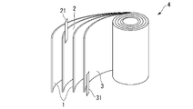
- FIG. 1A and 1B are schematic views showing an example of the lithium secondary battery of the present embodiment.
- the cylindrical lithium secondary battery 10 of the present embodiment is manufactured as follows.
- a pair of strip-shaped separators 1, a strip-shaped positive electrode 2 having a positive electrode lead 21 at one end, and a strip-shaped negative electrode 3 having a negative electrode lead 31 at one end are divided into a separator 1, a positive electrode 2, and a separator.
- the electrode group 4 is formed by laminating 1 and the negative electrode 3 in this order and winding them.
- the lithium secondary battery 10 can be manufactured by sealing the upper part of the battery can 5 with the top insulator 7 and the sealing body 8.
- the shape of the electrode group 4 is, for example, a columnar shape in which the cross-sectional shape when the electrode group 4 is cut in the direction perpendicular to the winding axis is a circle, an ellipse, a rectangle, or a rectangle with rounded corners. Can be mentioned.
- the shape of the lithium secondary battery having such an electrode group 4 the shape defined by IEC60086, which is a standard for batteries defined by the International Electrotechnical Commission (IEC), or JIS C8500 can be adopted. ..
- IEC60086 which is a standard for batteries defined by the International Electrotechnical Commission (IEC), or JIS C8500
- a cylindrical shape, a square shape, or the like can be mentioned.
- the lithium secondary battery is not limited to the above-mentioned winding type configuration, and may be a laminated type configuration in which a laminated structure of a positive electrode, a separator, a negative electrode, and a separator is repeatedly laminated.
- the laminated lithium secondary battery include so-called coin-type batteries, button-type batteries, and paper-type (or sheet-type) batteries.
- the positive electrode can be manufactured by first preparing a positive electrode mixture containing a CAM, a conductive material and a binder, and supporting the positive electrode mixture on a positive electrode current collector.
- a carbon material As the conductive material of the positive electrode, a carbon material can be used.
- the carbon material include graphite powder, carbon black (for example, acetylene black), and fibrous carbon material.
- the ratio of the conductive material in the positive electrode mixture is preferably 5 parts by mass or more and 20 parts by mass or less with respect to 100 parts by mass of CAM.
- thermoplastic resin As the binder contained in the positive electrode, a thermoplastic resin can be used.
- the thermoplastic resin include a polyimide resin, polyvinylidene fluoride (hereinafter, may be referred to as PVdF), a fluororesin such as polytetrafluoroethylene; a polyolefin resin such as polyethylene and polypropylene, WO2019 / 098384A1 or US2020 / 0274158A1. Resin can be mentioned.
- a band-shaped member made of a metal material such as Al, Ni, or stainless steel can be used.
- the positive electrode mixture is made into a paste using an organic solvent, and the obtained positive electrode mixture paste is applied to at least one surface side of the positive electrode current collector and dried.
- An example is a method of pressing and fixing.
- examples of the organic solvent that can be used include amide solvents such as N-methyl-2-pyrrolidone (hereinafter, may be referred to as NMP).
- Examples of the method of applying the positive electrode mixture paste to the positive electrode current collector include a slit die coating method, a screen coating method, a curtain coating method, a knife coating method, a gravure coating method, and an electrostatic spray method.
- the positive electrode can be manufactured by the method described above.
- the negative electrode of the lithium secondary battery may be capable of doping and dedoping lithium ions at a lower potential than that of the positive electrode, and is an electrode in which a negative electrode mixture containing a negative electrode active material is supported on a negative electrode current collector. Examples thereof include an electrode composed of a negative electrode active material alone.
- Negative electrode active material examples include carbon materials, chalcogen compounds (oxides, sulfides, etc.), nitrides, metals or alloys, which can be doped and dedoped with lithium ions at a lower potential than the positive electrode. Be done.
- Examples of the carbon material that can be used as the negative electrode active material include graphite such as natural graphite and artificial graphite, coke, carbon black, pyrolytic carbon, carbon fiber, and calcined organic polymer compound.
- Oxides that can be used as the negative electrode active material include the silicon oxides SnO 2 and SnO represented by the formula SiO x (where x is a positive real number) such as SiO 2 and SiO (here, the formula SnO x ).
- x is an oxide of tin represented by a positive real number); a metal composite oxide containing lithium and titanium such as Li 4 Ti 5 O 12 and LiVO 2 ;
- the metal that can be used as the negative electrode active material examples include lithium metal, silicon metal, and tin metal.
- a material that can be used as a negative electrode active material the material described in WO2019 / 098384A1 or US2020 / 0274158A1 may be used.
- These metals and alloys are mainly used alone as electrodes after being processed into a foil, for example.
- a carbon material containing graphite as a main component such as natural graphite and artificial graphite, is preferably used because of its high value (good cycle characteristics).
- the shape of the carbon material may be, for example, a flaky shape such as natural graphite, a spherical shape such as mesocarbon microbeads, a fibrous shape such as graphitized carbon fiber, or an agglomerate of fine powder.
- the negative electrode mixture may contain a binder, if necessary.
- the binder include thermoplastic resins, and specifically, PVdF, thermoplastic polyimide, carboxymethyl cellulose (hereinafter, may be referred to as CMC), and styrene-butadiene rubber (hereinafter, may be referred to as SBR).
- CMC carboxymethyl cellulose
- SBR styrene-butadiene rubber
- Negative electrode current collector examples of the negative electrode current collector included in the negative electrode include a band-shaped member made of a metal material such as Cu, Ni, and stainless steel as a forming material.
- separator of the lithium secondary battery for example, a material having a form such as a porous film, a non-woven fabric, or a woven fabric made of a material such as a polyolefin resin such as polyethylene or polypropylene, a fluororesin, or a nitrogen-containing aromatic polymer is used. Can be used. Further, two or more kinds of these materials may be used to form a separator, or these materials may be laminated to form a separator. Further, the separator described in JP-A-2000-030686 or US20090111025A1 may be used.
- the electrolytic solution contained in the lithium secondary battery contains an electrolyte and an organic solvent.
- the electrolyte contained in the electrolytic solution examples include lithium salts such as LiClO 4 , LiPF 6 , and LiBF 4 , and a mixture of two or more of these may be used. Further, the electrolyte described in WO2019 / 098384A1 or US2020 / 0274158A1 may be used. Among them, the electrolyte is at least selected from the group consisting of LiPF 6 , LiAsF 6 , LiSbF 6 , LiBF 4 , LiCF 3 SO 3 , LiN (SO 2 CF 3 ) 2 and LiC (SO 2 CF 3 ) 3 containing fluorine. It is preferable to use one containing one type.
- organic solvent contained in the electrolytic solution for example, the organic solvent described in propylene carbonate, ethylene carbonate, dimethyl carbonate, diethyl carbonate, ethylmethyl carbonate, WO2019 / 098384A1 or US2020 / 0274158A1 can be used.
- the organic solvent it is preferable to use a mixture of two or more of these, and a mixed solvent of cyclic carbonate and acyclic carbonate and a mixed solvent of cyclic carbonate and ethers are more preferable.
- a mixed solvent of the cyclic carbonate and the acyclic carbonate a mixed solvent containing ethylene carbonate, dimethyl carbonate and ethyl methyl carbonate is preferable.
- the electrolytic solution it is preferable to use an electrolytic solution containing a lithium salt containing fluorine such as LiPF 6 and an organic solvent having a fluorine substituent because the safety of the obtained lithium secondary battery is enhanced.
- a lithium salt containing fluorine such as LiPF 6
- an organic solvent having a fluorine substituent because the safety of the obtained lithium secondary battery is enhanced.
- the CAM having the above configuration is manufactured using the precursor described above, it is possible to manufacture a lithium secondary battery having a high discharge capacity and not easily deteriorated during high temperature storage.
- the positive electrode having the above configuration has the CAM having the above-mentioned configuration, it is possible to manufacture a lithium secondary battery having a high discharge capacity and not easily deteriorated during high temperature storage.
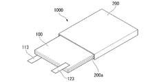
- FIGS. 2 and 3 are schematic views showing an example of an all-solid-state lithium secondary battery.
- FIG. 2 is a schematic view showing a laminate included in an all-solid-state lithium secondary battery.
- FIG. 3 is a schematic diagram showing the overall configuration of the all-solid-state lithium secondary battery.
- the all-solid-state lithium secondary battery 1000 includes a positive electrode 110, a negative electrode 120, a laminated body 100 having a solid electrolyte layer 130, and an exterior body 200 containing the laminated body 100. Further, the all-solid-state lithium secondary battery 1000 may have a bipolar structure in which a CAM and a negative electrode active material are arranged on both sides of a current collector. Specific examples of the bipolar structure include the structure described in JP-A-2004-95400. The materials constituting each member will be described later.
- the laminated body 100 may have an external terminal 113 connected to the positive electrode current collector 112 and an external terminal 123 connected to the negative electrode current collector 122.
- the positive electrode 110 and the negative electrode 120 sandwich the solid electrolyte layer 130 so as not to short-circuit each other.
- the all-solid-state lithium secondary battery 1000 has a separator between the positive electrode 110 and the negative electrode 120 as used in a conventional liquid-based lithium ion secondary battery to prevent a short circuit between the positive electrode 110 and the negative electrode 120. You may be doing it.
- the all-solid-state lithium secondary battery 1000 has an insulator (not shown) that insulates the laminate 100 and the exterior body 200, and a sealant (not shown) that seals the opening 200a of the exterior body 200.
- a container formed of a metal material having high corrosion resistance such as aluminum, stainless steel, and nickel-plated steel can be used. Further, it is also possible to use a container in which a laminated film having a corrosion resistant treatment on at least one surface is processed into a bag shape.
- Examples of the shape of the all-solid-state lithium secondary battery 1000 include a coin type, a button type, a paper type (or a sheet type), a cylindrical type, and a square type.
- the all-solid-state lithium secondary battery 1000 is shown as having one laminated body 100, but the present invention is not limited to this.
- the all-solid-state lithium-ion secondary battery 1000 may have a structure in which the laminated body 100 is a unit cell and a plurality of unit cells (laminated body 100) are enclosed inside the exterior body 200.
- the positive electrode 110 has a positive electrode active material layer 111 and a positive electrode current collector 112.
- the positive electrode active material layer 111 contains the CAM and the solid electrolyte according to one aspect of the present invention described above. Further, the positive electrode active material layer 111 may contain a conductive material and a binder.
- Solid electrolyte As the solid electrolyte contained in the positive electrode active material layer 111, a solid electrolyte having lithium ion conductivity and used in a known all-solid-state battery can be adopted.
- a solid electrolyte include an inorganic electrolyte and an organic electrolyte.
- the inorganic electrolyte include an oxide-based solid electrolyte, a sulfide-based solid electrolyte, and a hydride-based solid electrolyte.
- the organic electrolyte include polymer-based solid electrolytes. Examples of each electrolyte include the compounds described in WO2010 / 208872A1, US2016 / 0235510A1, US2012 / 0251871A1, and US2018 / 0159169A1, and examples thereof include the following compounds.
- oxide-based solid electrolyte examples include perovskite-type oxides, NASICON-type oxides, LISION-type oxides, and garnet-type oxides. Specific examples of each oxide include the compounds described in WO2020 / 208872A1, US2016 / 0235510A1, and US2020 / 0259213A1.
- garnet-type oxide examples include Li-La-Zr-based oxides such as Li 7 La 3 Zr 2 O 12 (also referred to as LLZ).
- the oxide-based solid electrolyte may be a crystalline material or an amorphous material.
- Examples of the sulfide-based solid electrolyte include Li 2 SP 2 S 5 series compounds, Li 2 S—SiS 2 series compounds, Li 2 S—GeS 2 series compounds, Li 2 SB 2 S 3 series compounds, and LiI-. Examples thereof include Si 2 SP 2 S 5 series compounds, LiI-Li 2 SP 2 O 5 series compounds, LiI-Li 3 PO 4-P 2 S 5 series compounds , and Li 10 GeP 2 S 12 series. ..
- system compound which refers to a sulfide-based solid electrolyte is a solid electrolyte mainly containing raw materials such as "Li 2 S” and "P 2 S 5 " described before “system compound”. It is used as a general term for.
- the Li 2 SP 2 S 5 system compound mainly contains Li 2 S and P 2 S 5 , and further contains a solid electrolyte containing other raw materials.
- the ratio of Li 2S contained in the Li 2 SP 2 S 5 system compound is, for example, 50 to 90% by mass with respect to the entire Li 2 SP 2 S 5 system compound .
- the ratio of P 2 S 5 contained in the Li 2 SP 2 S 5 system compound is, for example, 10 to 50% by mass with respect to the entire Li 2 SP 2 S 5 system compound.
- the ratio of other raw materials contained in the Li 2 SP 2 S 5 system compound is, for example, 0 to 30% by mass with respect to the entire Li 2 SP 2 S 5 system compound.
- the Li 2 SP 2 S 5 system compound also contains a solid electrolyte having a different mixing ratio of Li 2 S and P 2 S 5 .
- Li 2 SP 2 S 5 system compounds examples include Li 2 SP 2 S 5 , Li 2 SP 2 S 5 -LiI, Li 2 SP 2 S 5 -LiCl, and Li 2 SP 2 .
- examples thereof include S 5 -LiBr, Li 2 SP 2 S 5- LiI-LiBr, and the like.
- Li 2 S-SiS 2 compounds include Li 2 S-SiS 2 , Li 2 S-SiS 2 -LiI, Li 2 S-SiS 2 -LiBr, Li 2 S-SiS 2 -LiCl, and Li 2 S-SiS. 2 -B 2 S 3 -LiI, Li 2 S-SiS 2 -P 2 S 5 -LiI, Li 2 S-SiS 2 -P 2 S 5 -LiCl and the like can be mentioned.
- Li 2 S-GeS 2 compound examples include Li 2 S-GeS 2 and Li 2 S-GeS 2 -P 2 S 5 .
- the sulfide-based solid electrolyte may be a crystalline material or an amorphous material.
- Two or more types of solid electrolytes can be used in combination as long as the effects of the invention are not impaired.
- the conductive material that the positive electrode active material layer 111 may have, the material described in (conductive material) described above can be used. Further, as for the ratio of the conductive material in the positive electrode mixture, the ratio described in the above-mentioned (conductive material) can be similarly applied. Further, as the binder contained in the positive electrode, the material described in the above-mentioned (binder) can be used.
- Positive electrode current collector 112 included in the positive electrode 110 As the positive electrode current collector 112 included in the positive electrode 110, the material described in the above (positive electrode current collector) can be used.
- a method of pressure molding the positive electrode active material layer 111 on the positive electrode current collector 112 can be mentioned.
- a cold press or a hot press can be used for pressure molding.
- a mixture of CAM, a solid electrolyte, a conductive material, and a binder is made into a paste using an organic solvent to form a positive electrode mixture, and the obtained positive electrode mixture is applied to at least one surface of the positive electrode current collector 112, dried, and pressed.
- the positive electrode active material layer 111 may be supported on the positive electrode current collector 112 by sticking to the positive electrode collector 112.
- a mixture of CAM, a solid electrolyte, and a conductive material is made into a paste using an organic solvent to form a positive electrode mixture, and the obtained positive electrode mixture is applied to at least one surface side of the positive electrode current collector 112, dried, and sintered. Therefore, the positive electrode active material layer 111 may be supported on the positive electrode current collector 112.
- the organic solvent that can be used for the positive electrode mixture the same organic solvent that can be used when the positive electrode mixture described above (positive electrode current collector) is made into a paste can be used.
- Examples of the method of applying the positive electrode mixture to the positive electrode current collector 112 include the method described in the above-mentioned (positive electrode current collector).
- the positive electrode 110 can be manufactured by the method described above.
- the negative electrode 120 has a negative electrode active material layer 121 and a negative electrode current collector 122.
- the negative electrode active material layer 121 contains a negative electrode active material. Further, the negative electrode active material layer 121 may contain a solid electrolyte and a conductive material. As the negative electrode active material, the negative electrode current collector, the solid electrolyte, the conductive material, and the binder, those described above can be used.
- Solid electrolyte layer 130 has the above-mentioned solid electrolyte.
- the solid electrolyte layer 130 can be formed by depositing an inorganic solid electrolyte on the surface of the positive electrode active material layer 111 of the above-mentioned positive electrode 110 by a sputtering method.
- the solid electrolyte layer 130 can be formed by applying a paste-like mixture containing a solid electrolyte to the surface of the positive electrode active material layer 111 of the above-mentioned positive electrode 110 and drying it. After drying, the solid electrolyte layer 130 may be formed by press molding and further pressurizing by a cold isotropic pressure pressurization method (CIP).
- CIP cold isotropic pressure pressurization method
- the lithium secondary battery having the above configuration since it has the CAM having the above configuration, it is possible to manufacture a lithium secondary battery having a high discharge capacity and not easily deteriorated during high temperature storage.
- composition analysis of the precursor and the CAM produced by the method described later was carried out by the method described in the above [Precursor and CAM composition analysis], respectively.
- conductive material acetylene black
- binder PVdF
- the obtained positive electrode mixture was applied to an Al foil having a thickness of 40 ⁇ m as a current collector and vacuum dried at 150 ° C. for 8 hours to obtain a positive electrode.
- the electrode area of this positive electrode was 1.65 cm 2 .
- the obtained negative electrode mixture was applied to a Cu foil having a thickness of 12 ⁇ m as a current collector and vacuum dried at 60 ° C. for 8 hours to obtain a negative electrode.
- the electrode area of this negative electrode was 1.77 cm 2 .
- the positive electrode produced in ⁇ Preparation of positive electrode> was placed on an aluminum laminated film with the aluminum foil surface facing down, and a laminated film separator (polyethylene porous film (thickness 27 ⁇ m)) was placed on the laminated film separator.
- a laminated film separator polyethylene porous film (thickness 27 ⁇ m)
- the negative electrode prepared in ⁇ Preparation of Negative Electrode> was placed on the upper side of the laminated film separator with the copper foil side facing up, and the aluminum laminated film was placed on it. Further, heat sealing was performed leaving the injection portion of the electrolytic solution. Then, the mixture was transferred to a dry bench having a dry atmosphere with a dew point temperature of ⁇ 50 ° C.
- the electrolytic solution injection portion was heat-sealed to prepare a laminated cell.
- ⁇ High temperature storage test> Using the laminated cell obtained in ⁇ Preparation of lithium secondary battery>, a high temperature storage test was performed according to the method described in the above-mentioned [High temperature storage test], and the discharge capacity before storage and the discharge capacity after storage were measured. The storage capacity retention rate was calculated from these values.
- Example 1 [Nuclear development process] Using a reaction tank equipped with a stirrer and an overflow pipe, a concentration tank connected to the overflow pipe, and a device having a mechanism for circulating from the concentration tank to the reaction tank, water is poured into the reaction tank and then hydroxide is added. An aqueous sodium solution was added and the liquid temperature was maintained at 50 ° C.
- a nickel sulfate aqueous solution, a cobalt sulfate aqueous solution, and a manganese sulfate aqueous solution are mixed at a ratio of Ni, Co, and Mn so that the atomic ratio is 0.58: 0.20: 0.22 to prepare a metal raw material mixture. Prepared.
- a disc turbine blade having a blade diameter of 50 mm was installed as a stirring blade with respect to 7 L of the solution in the reaction tank at a position 4 cm from the bottom of the reaction tank, and the pH of the solution in the reaction tank was 11.
- An aqueous sodium hydroxide solution was added dropwise in a timely manner so as to reach 7 (measurement temperature: 40 ° C.).
- the metal raw material mixed solution was continuously added to the reaction vessel in which the nucleation step was performed at a liquid feeding rate of 8 mL / min and an aqueous ammonium sulfate solution at a liquid feeding rate of 1.2 mL / min.
- An aqueous sodium hydroxide solution was added dropwise in a timely manner so that the pH of the solution in the reaction vessel became 11.0 (measurement temperature: 40 ° C.). After 15.5 hours had passed from the start of the nuclear growth step, all liquid feeding was stopped and the crystallization reaction was completed.
- the obtained nickel-cobalt-manganese-metal composite hydroxide-containing slurry was washed and dehydrated, dried at 105 ° C. for 20 hours and sieved to obtain a precursor which is a nickel-cobalt-manganese-metal composite hydroxide.
- Various measurements and composition analyzes were performed on the obtained precursors. These results are shown in Table 1.
- Example 2 Examples except that the concentration of the complexing agent in the reaction vessel of the nuclear generation step was changed to 5 g / L and the pH in the reaction vessel of the nuclear generation step was changed to 12.3 (measurement temperature: 40 ° C.).
- a precursor which is a nickel-cobalt manganese metal composite hydroxide was produced in the same manner as in 1.
- Example 1 The stirring blade of the blade type stirrer was changed to an inclined paddle blade with a blade diameter of 50 mm, the stirring speed was changed to 1500 rpm, and the concentration of the complexing agent in the reaction vessel in the nuclear generation step was changed to 5 g / L.
- a precursor that is a hydroxide was produced.
- Example 2 The stirring blade of the blade type stirrer was changed to an inclined paddle blade with a blade diameter of 50 mm, the stirring speed was changed to 1500 rpm, and the concentration of the complexing agent in the reaction vessel in the nuclear generation step was changed to 1 g / L.
- a precursor which is a nickel-cobalt-manganese metal composite hydroxide was produced in the same manner as in Example 1 except that the pH in the reaction vessel in the nuclear generation step was set to 12.8 (measurement temperature: 40 ° C.).
- the composition, stirring speed, complexing agent concentration, ⁇ , A, V, ⁇ , B, X, and pore diameter of the precursors of Examples 1 to 3 and Comparative Examples 1 and 2 are 10 nm or more and 200 nm or less. Cumulative pore volume (cm 3 / g) and cumulative pore specific surface area (m 2 / g), BET specific surface area, and tap density are described.
- N / C / M / A means "Ni / Co / Mn / Al”.
- Example 5 A CAM was obtained in the same manner as in Example 4 except that the precursor of Example 2 was used.
- Comparative Example 3 A CAM was obtained in the same manner as in Example 4 except that the precursor of Comparative Example 1 was used and the second firing temperature was set to 1000 ° C.
- the lithium secondary battery using CAM produced by using the precursor of the present embodiment has a pre-storage discharge capacity of 180 mAh / g or more and a storage capacity retention rate of 85% or more under high temperature conditions. It was confirmed that the discharge capacity was high and the deterioration was not likely to occur during high temperature storage.
Landscapes
- Chemical & Material Sciences (AREA)
- Inorganic Chemistry (AREA)
- Chemical Kinetics & Catalysis (AREA)
- Electrochemistry (AREA)
- General Chemical & Material Sciences (AREA)
- Organic Chemistry (AREA)
- Engineering & Computer Science (AREA)
- Materials Engineering (AREA)
- Manufacturing & Machinery (AREA)
- Battery Electrode And Active Subsutance (AREA)
- Secondary Cells (AREA)
- Inorganic Compounds Of Heavy Metals (AREA)
Abstract
Description
本願は、2020年11月19日に、日本に出願された特願2020-192685号に基づき優先権を主張し、その内容をここに援用する。
本発明は上記事情に鑑みてなされたものであって、放電容量が高く、且つ高温保存時に劣化しにくいリチウム二次電池を提供でき、正極活物質の原料となる前駆体を提供することを課題とする。さらに、これを用いたリチウム二次電池用正極活物質、リチウム二次電池用正極及びリチウム二次電池を提供することを課題とする。
[1]リチウム二次電池用正極活物質の前駆体であって、少なくともNiを含み、下記式(1)より算出される値αが2.3m/ng以下である、前駆体。
α=A2/(4πV)÷1000 ・・・(1)
(式(1)中、Aは、液体窒素温度で測定された前記前駆体の窒素脱離等温線をBJH法で解析して得られる細孔比表面積のうち、細孔直径が2.6nm以上200nm以下の累積細孔比表面積(m2/g)である。
Vは、液体窒素温度で測定された前記前駆体の窒素脱離等温線をBJH法で解析して得られる細孔容積のうち、細孔直径が2.6nm以上200nm以下の累積細孔容積(cm3/g)である。)
[2]下記式(2)より算出される値βが2.8m/ng以下である、[1]に記載の前駆体。
β=B2/(4πX)÷1000 ・・・(2)
(式(2)中、Bは、液体窒素温度で測定された前記前駆体の窒素脱離等温線をBJH法で解析して得られる細孔比表面積のうち、細孔直径が2.6nm以上50nm以下の累積細孔比表面積(m2/g)である。
Xは、液体窒素温度で測定された前記前駆体の窒素脱離等温線をBJH法で解析して得られる細孔容積のうち、細孔直径が2.6nm以上50nm以下の累積細孔容積(cm3/g)である。)
[3]BET比表面積が1.0m2/g以上25m2/g以下である、[1]又は[2]に記載の前駆体。
[4]タップ密度が0.8g/cm3以上2.7g/cm3以下である、[1]~[3]のいずれか1つに記載の前駆体。
[5]少なくともNiを含み、下記式(3)より算出される値γが4.0m/μg以上40.0m/μg以下である、リチウム二次電池用正極活物質。
γ=C2/(4πY) ・・・(3)
(式(3)中、Cは、液体窒素温度で測定された前記リチウム二次電池用正極活物質の窒素脱離等温線をBJH法で解析して得られる細孔比表面積のうち、細孔直径が2.6nm以上200nm以下の累積細孔比表面積(m2/g)である。
Yは、液体窒素温度で測定された前記リチウム二次電池用正極活物質の窒素脱離等温線をBJH法で解析して得られる細孔容積のうち、細孔直径が2.6nm以上200nm以下の累積細孔容積(cm3/g)である。)
[6]下記式(4)より算出される値δが10m/μg以上50m/μg以下である、[5]に記載のリチウム二次電池用正極活物質。
δ=E2/(4πZ) ・・・(4)
(式(4)中、Eは、液体窒素温度で測定された前記リチウム二次電池用正極活物質の窒素脱離等温線をBJH法で解析して得られる細孔比表面積のうち、細孔直径が2.6nm以上50nm以下の累積細孔比表面積(m2/g)である。
Zは、液体窒素温度で測定された前記リチウム二次電池用正極活物質の窒素脱離等温線をBJH法で解析して得られる細孔容積のうち、細孔直径が2.6nm以上50nm以下の累積細孔容積(cm3/g)である。)
[7]下記組成式(I)で表される[5]又は[6]に記載のリチウム二次電池用正極活物質。
Li[Lia(Ni1-x-yCoxMy)1-a]O2 ・・・(I)
(ただし、式(I)において、MはFe、Cu、Mg、Mn、Al、W、B、Mo、Zn、Sn、Zr、Ga、La、Ti、Nb及びVからなる群より選ばれる少なくとも1種の元素であり、-0.10≦a≦0.30、0≦x≦0.45、及び0≦y≦0.45を満たす。)
[8]BET比表面積が0.3m2/g以上4.0m2/g以下である、[5]~[7]のいずれか1つに記載のリチウム二次電池用正極活物質。
[9]タップ密度が1.0g/cm3以上2.8g/cm3以下である[5]~[8]のいずれか1つに記載のリチウム二次電池用正極活物質。
[10][5]~[9]のいずれか1つに記載のリチウム二次電池用正極活物質を含むリチウム二次電池用正極。
[11][10]に記載のリチウム二次電池用正極を有するリチウム二次電池。
以下、リチウム二次電池用正極活物質(Cathode Active Material for lithium secondary batteries)を以下「CAM」と称する。
本明細書において、放電容量の高さと高温保存時の劣化度合いは、以下の方法により評価する。
[高温保存試験]
リチウム二次電池を用いて、試験温度25℃において電流設定値0.2CAとし、それぞれ定電流定電圧充電と定電流放電を行う。充電最大電圧は4.3V、放電最小電圧は2.5Vとする。放電容量を測定し、得られた値を「保存前放電容量」とする。保存前放電容量が180mAh/g以上であると、「放電容量が高い」と評価する。
前駆体及びCAMの組成分析は、前駆体及びCAMの粉末をそれぞれ塩酸に溶解させた後、ICP発光分光分析装置を用いて測定できる。
ICP発光分光分析装置としては、例えば、株式会社パーキンエルマー製、Optima7300が使用できる。
前駆体又はCAMのBET比表面積は、BET比表面積測定装置により測定できる。具体的には、例えば、前駆体又はCAMの粉末1gをそれぞれ窒素雰囲気中、105℃で30分間乾燥させた後、マウンテック社製Macsorb(登録商標)を用いて測定すればよい(単位:m2/g)。
タップ密度は、JIS R 1628-1997に記載の方法で求めた値を用いる。
本実施形態はCAMの前駆体である。前駆体は少なくともNiを含む。
前駆体は、CAMの原料となる。以下、「前駆体」と記載する場合には、本実施形態の前駆体を意味する。
以下、複数の実施形態や数値範囲では、好ましい例や条件を共有してもよい。
本実施形態の一つの態様において、前駆体は粉末である。
本実施形態の一つの態様において、前駆体は少なくともNiを含む。
α=A2/(4πV)÷1000 ・・・(1)
(式(1)中、Aは、液体窒素温度で測定された前駆体の窒素脱離等温線をBJH法で解析して得られる細孔比表面積のうち、細孔直径が2.6nm以上200nm以下の累積細孔比表面積(m2/g)である。
Vは、液体窒素温度で測定された前駆体の窒素脱離等温線をBJH法で解析して得られる細孔容積のうち、細孔直径が2.6nm以上200nm以下の累積細孔容積(cm3/g)である。)
式(1)中、A及びVは、以下の測定方法により求める。
まず、前駆体について、真空加熱処理装置を用いて、80℃で8時間真空脱気する。
真空加熱処理装置としては、例えば、マイクロトラック・ベル株式会社製BELSORP-vacIIが使用できる。
脱離等温線における前駆体の単位重量あたりの窒素脱離量は、標準状態(STP;Standard Temperature and Pressure)の気体窒素の体積で表されるよう算出する。
h=S2/4πL ・・・(H)
αが上記上限値以下であると、細孔を円筒形と仮定したときのモデルにおいて、単純な細孔経路を有することを意味する。
よって、αが上記上限値以下である前駆体を原料とするCAMを用いたリチウム二次電池は、放電容量が高く、且つ高温保存時に劣化しにくいと考えられる。
αの上記上限値及び下限値は、任意に組み合わせることができる。
組み合わせの例としては、αは、0.1m/ng以上2.3m/ng以下、0.2m/ng以上2.0m/ng以下、0.3m/ng以上1.8m/ng以下が挙げられる。
β=B2/(4πX)÷1000 ・・・(2)
(式(2)中、Bは、液体窒素温度で測定された前駆体の窒素脱離等温線をBJH法で解析して得られる細孔比表面積のうち、細孔直径2.6nm以上50nm以下の累積細孔比表面積(m2/g)である。
Xは、液体窒素温度で測定された前駆体の窒素脱離等温線をBJH法で解析して得られる細孔容積のうち、細孔直径2.6nm以上50nm以下の累積細孔容積(cm3/g)である。)
B及びXの測定方法は、式(1)におけるA及びVの測定方法と同様である。
βは2.8m/ng以下であり、2.7m/ng以下が好ましく、2.5m/ng以下がより好ましい。
よって、前駆体を原料とするCAMを用いたリチウム二次電池は、高温で保存した場合に、より劣化しにくくなる。
βの上記上限値及び下限値は、任意に組み合わせることができる。
組み合わせの例としては、βは、0.1m/ng以上2.8m/ng以下、0.2m/ng以上2.7m/ng以下、0.3m/ng以上2.5m/ng以下が挙げられる。
前駆体は、少なくともNiを含み、下記組成式(A)で表されることが好ましい。下記組成式(A)で表される前駆体は、酸化物又は水酸化物であり、水酸化物であることがより好ましい。
Ni1-x-yCoxMyOz(OH)2-b ・・・組成式(A)
(組成式(A)中、0≦x≦0.45、0≦y≦0.45、0≦z≦3、-0.5≦b≦2であり、MはFe、Cu、Mg、Mn、Al、W、B、Mo、Zn、Sn、Zr、Ga、La、Ti、Nb及びVからなる群より選ばれる少なくとも1種の元素である。)
xは、0.005以上が好ましく、0.01以上がより好ましく、0.02以上がさらに好ましく、0.05以上が特に好ましい。
またxは、0.44以下が好ましく、0.40以下がより好ましく、0.35以下がさらに好ましく、0.30以下が特に好ましい。
xの上限値及び下限値は任意に組み合わせることができる。
組み合わせの例としては、xは、0≦x≦0.40、0.01≦x≦0.44、0.02≦x≦0.30、0.03≦x≦0.40、0.05≦x≦0.35が挙げられる。
yは、0.01以上が好ましく、0.02以上がより好ましく、0.03以上がさらに好ましく、0.1以上が特に好ましい。
またyは、0.44以下が好ましく、0.42以下がより好ましく、0.40以下がさらに好ましく、0.35以下が特に好ましい。
yの上限値及び下限値は任意に組み合わせることができる。
組み合わせとしては、yは、0.01≦y≦0.44が好ましく、0.02≦y≦0.42がより好ましく、0.03≦y≦0.40がさらに好ましく、0.1≦y≦0.35が特に好ましい。
zは、0.1以上が好ましく、0.2以上がより好ましく、0.3以上が特に好ましい。
またzは、2.9以下が好ましく、2.8以下がより好ましく、2.7以下がさらに好ましい。
zの上限値及び下限値は任意に組み合わせることができる。
組み合わせの例としては、zは、0.1≦z≦2.9が好ましく、0.2≦z≦2.8がより好ましく、0.3≦z≦2.7が特に好ましい。
bは、-0.45以上が好ましく、-0.4以上がより好ましく、-0.35以上がさらに好ましい。
またbは、1.8以下が好ましく、1.6以下がより好ましく、1.4以下がさらに好ましい。
bの上限値及び下限値は任意に組みわせることができる。
組み合わせの例としては、bは、-0.45≦b≦1.8が好ましく、-0.4≦b≦1.6がより好ましく、-0.35≦b≦1.4が特に好ましい。
x+yは、0.05以上0.70以下が好ましく、0.10以上0.50以下がより好ましい。
組成式(A)中、Mは、サイクル特性が高いリチウム二次電池を得る観点から、Mn、Mg、Al、W、B、Zrからなる群より選択される1種以上の元素であることが好ましく、Zr、Al、及びMnからなる群より選ばれる1種以上の元素がより好ましい。
本実施形態のCAMは、上述した前駆体を、リチウム化合物と混合して焼成することにより得られる。
本実施形態の一つの態様において、CAMは粉末である。
γ=C2/(4πY) ・・・(3)
(式(3)中、Cは、液体窒素温度で測定されたCAMの窒素脱離等温線をBJH法で解析して得られる細孔比表面積のうち、細孔直径2.6nm以上200nm以下の累積細孔比表面積(m2/g)である。
Yは、液体窒素温度で測定されたCAMの窒素脱離等温線をBJH法で解析して得られる細孔容積のうち、細孔直径2.6nm以上200nm以下の累積細孔容積(cm3/g)である。)
C及びYは、以下の測定により求める。
まず、真空加熱処理装置を用いて、温度150℃で8時間、CAMを真空脱気する。
真空加熱処理装置としては、例えば、マイクロトラック・ベル株式会社製BELSORP-vacIIが使用できる。
真空脱気後、上記(窒素吸着等温線測定及び窒素脱離等温線測定)に記載の測定方法と同様の操作を実施してC及びYを測定する。
γが上記上限値以下であると、細孔を円筒形と仮定したときのモデルにおいて、CAMが単純な細孔経路を有することを意味する。
δ=E2/(4πZ) ・・・(4)
(式(4)中、Eは、液体窒素温度で測定されたCAMの窒素脱離等温線をBJH法で解析して得られる細孔比表面積のうち、細孔直径2.6nm以上50nm以下の累積細孔比表面積(m2/g)である。
Zは、液体窒素温度で測定されたCAMの窒素脱離等温線をBJH法で解析して得られる細孔容積のうち、細孔直径2.6nm以上50nm以下の累積細孔容積(cm3/g)である。)
E及びZの測定方法は、上記(窒素吸着等温線測定及び窒素脱離等温線測定)に記載の測定方法と同様である。
また、BET比表面積が上記下限値以上であるCAMはリチウムイオンとの反応面積が大きい。このため、このようなCAMを用いたリチウム二次電池は、放電容量が高くなると考えられる。
上記上限値と上記下限値は任意に組み合わせることができる。組み合わせの例として、タップ密度が、1.1g/cm3以上2.8g/cm3以下、1.2g/cm3以上2.5g/cm3以下、1.2g/cm3以下2.3g/cm3以下が挙げられる。
Li[Lia(Ni1-x-yCoxMy)1-a]O2…(I)
(ただし、MはFe、Cu、Mg、Mn、Al、W、B、Mo、Zn、Sn、Zr、Ga、La、Ti、Nb及びVからなる群より選ばれる少なくとも1種の元素であり、-0.10≦a≦0.30、0≦x≦0.45、及び0≦y≦0.45を満たす。)
サイクル特性がよいリチウム二次電池を得る観点から、前記組成式(I)におけるaは0を超えることが好ましく、0.01以上であることがより好ましく、0.02以上であることがさらに好ましい。また、前記組成式(I)におけるaは0.25以下であることが好ましく、0.10以下であることがより好ましい。
組成式(I)におけるxは、0.005以上であることが好ましく、0.01以上であることがより好ましく、0.02以上であることがさらに好ましく、0.05以上であることが特に好ましい。また、前記組成式(I)におけるxは0.44以下であることが好ましく、0.40以下であることがより好ましく、0.35以下であることがさらに好ましく、0.30以下であることが特に好ましい。
また、サイクル特性が高いリチウム二次電池を得る観点から、前記組成式(I)におけるyは0.01以上であることが好ましく、0.02以上であることがより好ましく、0.03以上であることがさらに好ましく、0.1以上であることが特に好ましい。また、前記組成式(I)におけるyは0.44以下であることが好ましく、0.42以下であることがより好ましく、0.40以下であることがさらに好ましく、0.35以下であることが特に好ましい。
前記組成式(I)におけるMはFe、Cu、Mg、Mn、Al、W、B、Mo、Zn、Sn、Zr、Ga、La、Ti、Nb及びVからなる群より選択される1種以上の元素を表す。
CAMの結晶構造は、層状である。CAMの結晶構造は、六方晶型の結晶構造又は単斜晶型の結晶構造であることがより好ましい。
前駆体を製造する方法について説明する。
前駆体は、半連続法(セミバッチ法)により製造する。
具体的には、まず前駆体の粒子の核を生成させ、一旦すべての原料液の送液を停止し、その後、核を成長させる。
つまり、従来の連続晶析法のように同じ反応槽内において核生成工程と核成長工程を同時に進行させる方法とは異なる。
金属原料混合液及び錯化剤を反応させ、Ni1-x-yCoxMny(OH)2(0<x≦0.45、0<y≦0.45)で表される金属複合水酸化物の核を生成する。金属原料混合液は、ニッケル塩溶液、コバルト塩溶液、マンガン塩溶液の混合液である。
サンプリングした混合液の温度が40℃よりも高い場合には、混合液を冷却して40℃になったときにpHを測定する。
攪拌回転数の一例をあげると、下記の反応装置例において、攪拌回転数は1500rpmを超えることが好ましく、1600rpm以上がより好ましく、1700rpm以上がさらに好ましい。このような攪拌条件で攪拌することにより、供給した各原料液が均一に混合されやすい。
反応槽の液量:7L。
攪拌翼の羽根径:50mm。
攪拌翼の位置:反応槽の底から3cm以上4cm以下。
送液停止後、核生成工程を実施した反応槽と同一の反応槽に金属原料混合液、錯化剤及びアルカリ性水溶液をそれぞれ連続的に同時に供給する。これにより核が成長する。
核成長工程においては、例えばpH9以上12以下、好ましくはpH9以上11.5以下の範囲内で制御する。
以上の反応後、得られた金属複合水酸化物含有スラリーを洗浄した後、乾燥し、ニッケルコバルトマンガン金属複合水酸化物としての前駆体が得られる。
上記脱水工程によって得られた前駆体は、大気雰囲気下105℃以上200℃以下の条件で1時間以上20時間以下、乾燥させる。
CAMの製造方法は、前記前駆体の製造方法によって得られた前駆体と、リチウム化合物と混合し、混合物を得る混合工程と、得られた混合物を焼成する焼成工程を有する。
本工程では、前駆体と、リチウム化合物とを混合し、混合物を得る。
リチウム化合物は、炭酸リチウム、硝酸リチウム、酢酸リチウム、水酸化リチウム、酸化リチウム、塩化リチウム、フッ化リチウムのうち何れか一つ、又は、二つ以上を混合して使用することができる。これらの中では、水酸化リチウム及び炭酸リチウムのいずれか一方又は両方が好ましい。
前駆体と、リチウム化合物とを、最終目的物の組成比を勘案して混合する。例えば、ニッケルコバルトマンガン金属複合水酸化物を用いる場合、リチウム化合物と当該金属複合水酸化物は、LiNi1-x-yCoxMnzO2の組成比に対応する割合で用いられる。また、リチウムが過剰(含有モル比が1超)なCAMを製造する場合には、リチウム化合物に含まれるLiと、金属複合水酸化物に含まれる金属元素とのモル比が1を超える比率となる割合で混合する。
前駆体とリチウム化合物との混合物を焼成することによって、CAMが得られる。
なお、焼成には、所望の組成に応じて乾燥空気、酸素雰囲気、不活性雰囲気等を用いてもよい。
複数回の焼成段階を有する場合、最も高い温度で焼成する工程を本焼成と記載する。本焼成の前には、本焼成よりも低い温度で焼成する仮焼成を行ってもよい。
組み合わせの例としては、600℃以上1200℃以下、700℃以上1100℃以下、800℃以上1000℃以下が挙げられる。
次いで、リチウム二次電池の構成を説明しながら、上述の方法によって製造されるCAMを、リチウム二次電池のCAMとして用いたリチウム二次電池用正極(以下、正極と称する。)、およびこの正極を有するリチウム二次電池について説明する。
(正極)
正極は、まずCAM、導電材およびバインダーを含む正極合剤を調製し、正極合剤を正極集電体に担持させることで製造することができる。
正極が有する導電材としては、炭素材料を用いることができる。炭素材料として黒鉛粉末、カーボンブラック(例えばアセチレンブラック)、繊維状炭素材料などを挙げることができる。
正極が有するバインダーとしては、熱可塑性樹脂を用いることができる。この熱可塑性樹脂としては、ポリイミド樹脂、ポリフッ化ビニリデン(以下、PVdFということがある。)、ポリテトラフルオロエチレンなどのフッ素樹脂;ポリエチレン、ポリプロピレンなどのポリオレフィン樹脂、WO2019/098384A1またはUS2020/0274158A1に記載の樹脂を挙げることができる。
正極が有する正極集電体としては、Al、Ni、ステンレスなどの金属材料を形成材料とする帯状の部材を用いることができる。
(負極)
リチウム二次電池が有する負極は、正極よりも低い電位でリチウムイオンのドープかつ脱ドープが可能であればよく、負極活物質を含む負極合剤が負極集電体に担持されてなる電極、および負極活物質単独からなる電極を挙げることができる。
負極が有する負極活物質としては、炭素材料、カルコゲン化合物(酸化物、硫化物など)、窒化物、金属又は合金で、正極よりも低い電位でリチウムイオンのドープかつ脱ドープが可能な材料が挙げられる。
負極活物質として使用可能な材料として、WO2019/098384A1またはUS2020/0274158A1に記載の材料を用いてもよい。
負極が有する負極集電体としては、Cu、Ni、ステンレスなどの金属材料を形成材料とする帯状の部材を挙げることができる。
リチウム二次電池が有するセパレータとしては、例えば、ポリエチレン、ポリプロピレンなどのポリオレフィン樹脂、フッ素樹脂、含窒素芳香族重合体などの材質からなる、多孔質膜、不織布、織布などの形態を有する材料を用いることができる。また、これらの材質を2種以上用いてセパレータを形成してもよいし、これらの材料を積層してセパレータを形成してもよい。また、JP-A-2000-030686やUS20090111025A1に記載のセパレータを用いてもよい。
リチウム二次電池が有する電解液は、電解質および有機溶媒を含有する。
次いで、全固体リチウム二次電池の構成を説明しながら、前駆体を用いて製造されるCAMを、全固体リチウム二次電池のCAMとして用いた正極、及びこの正極を有する全固体リチウム二次電池について説明する。
各部材を構成する材料については、後述する。
正極110は、正極活物質層111と正極集電体112とを有している。
正極活物質層111に含まれる固体電解質としては、リチウムイオン伝導性を有し、公知の全固体電池に用いられる固体電解質を採用することができる。このような固体電解質としては、無機電解質及び有機電解質を挙げることができる。無機電解質としては、酸化物系固体電解質、硫化物系固体電解質及び水素化物系固体電解質を挙げることができる。有機電解質としては、ポリマー系固体電解質を挙げることができる。各電解質としては、WO2020/208872A1、US2016/0233510A1、US2012/0251871A1、US2018/0159169A1に記載の化合物が挙げられ、例えば、以下の化合物が挙げられる。
酸化物系固体電解質としては、例えば、ペロブスカイト型酸化物、NASICON型酸化物、LISICON型酸化物及びガーネット型酸化物などが挙げられる。各酸化物の具体例は、WO2020/208872A1、US2016/0233510A1、US2020/0259213A1に記載の化合物が挙げられる。
硫化物系固体電解質としては、Li2S-P2S5系化合物、Li2S-SiS2系化合物、Li2S-GeS2系化合物、Li2S-B2S3系化合物、LiI-Si2S-P2S5系化合物、LiI-Li2S-P2O5系化合物、LiI-Li3PO4-P2S5系化合物及びLi10GeP2S12などを挙げることができる。
正極活物質層111が有してもよい導電材としては、上述の(導電材)で説明した材料を用いることができる。また、正極合剤中の導電材の割合についても同様に上述の(導電材)で説明した割合を適用することができる。また、正極が有するバインダーとしては、上述の(バインダー)で説明した材料を用いることができる。
正極110が有する正極集電体112としては、上述の(正極集電体)で説明した材料を用いることができる。
負極120は、負極活物質層121と負極集電体122とを有している。負極活物質層121は、負極活物質を含む。また、負極活物質層121は、固体電解質、導電材を含むこととしてもよい。負極活物質、負極集電体、固体電解質、導電材、バインダーは、上述したものを用いることができる。
固体電解質層130は、上述の固体電解質を有している。
後述の方法で製造される前駆体及びCAMの組成分析は、上記[前駆体及びCAMの組成分析]に記載の方法によりそれぞれ実施した。
後述の方法により製造される前駆体について、下記式(1)より算出される値αを算出した。
α=A2/(4πV)÷1000 ・・・(1)
式(1)中、A及びVは、上述の[A及びVの測定方法]に記載の方法により算出した。
後述の方法により製造される前駆体について、下記式(2)より算出される値βを算出した。
β=B2/(4πX)÷1000 ・・・(2)
式(2)中、B及びXは、上述の[B及びXの測定方法]に記載の方法により算出した。
後述の方法により製造されるCAMについて、下記式(3)より算出される値γを算出した。
γ=C2/(4πY) ・・・(3)
式(3)中、C及びYは、上述の[C及びYの測定方法]に記載の方法により算出した。
後述の方法により製造されるCAMについて、下記式(4)より算出される値δを算出した。
δ=E2/(4πZ) ・・・(4)
式(4)中、E及びZは、上述の[E及びZの測定方法]に記載の方法により算出した。
前駆体又はCAMのBET比表面積の測定は、上記[前駆体及びCAMのBET比表面積の測定]に記載の方法により実施した。
前駆体又はCAMのタップ密度の測定は、上記[前駆体及びCAMのタップ密度の測定]に記載の方法により実施した。
CAMと導電材(アセチレンブラック)とバインダー(PVdF)とを、CAM:導電材:バインダー=92:5:3(質量比)の組成となる割合で加えて混練することにより、ペースト状の正極合剤を調製した。正極合剤の調製時には、N-メチル-2-ピロリドンを有機溶媒として用いた。
次に、負極活物質として人造黒鉛(日立化成株式会社製MAGD)と、バインダーとしてCMC(第一工業薬製株式会社製)とSBR(日本エイアンドエル株式会社製)とを、負極活物質:CMC:SBR=98:1:1(質量比)の組成となる割合で加えて混練することにより、ペースト状の負極合剤を調製した。負極合剤の調製時には、溶媒としてイオン交換水を用いた。
<正極の作製>で作製した正極を、アルミ箔面を下に向けてアルミラミネートフィルムに置き、その上に積層フィルムセパレータ(ポリエチレン製多孔質フィルム(厚み27μm))を置いた。次に、積層フィルムセパレータの上側に<負極の作製>で作製した負極を銅箔面を上にして置き、その上にアルミラミネートフィルムを置いた。さらに、電解液の注入部分を残してヒートシールした。その後、露点温度マイナス50℃以下の乾燥雰囲気のドライベンチ内に移し、真空注液機を用いて、電解液を1mL注入した。電解液は、エチレンカーボネートとジメチルカーボネートとエチルメチルカーボネートの16:10:74(体積比)混合液にビニレンカーボネートを1体積%加え、そこにLiPF6を1.3mol/lとなる割合で溶解したものを用いた。
最後に、電解液注液部分をヒートシールし、ラミネートセルを作製した。
<リチウム二次電池の作製>で得られたラミネートセルを用いて、上述の[高温保存試験]に記載の方法に従って、高温保存試験を行い、保存前放電容量および保存後放電容量を測定し、これらの値から保存容量維持率を求めた。
[核発成工程]
攪拌器及びオーバーフローパイプを備えた反応槽内と、オーバーフローパイプに連結された濃縮槽、および濃縮槽から反応槽へ循環を行う機構を有する装置を用い、反応槽に水を入れた後、水酸化ナトリウム水溶液を添加し、液温を50℃に保持した。
続いて、核生成工程を行った反応槽に、金属原料混合液を8mL/min、硫酸アンモニウム水溶液を1.2mL/minの送液速度で連続的に添加した。反応槽内の溶液のpHが11.0(測定温度:40℃)になるよう水酸化ナトリウム水溶液を適時滴下した。核成長工程開始から15.5時間経過した後、すべての送液を停止し晶析反応を終了した。
核発生工程の反応槽内の錯化剤の濃度を5g/Lに変更したこと、核発生工程の反応槽内のpHを12.3(測定温度:40℃)に変更したこと以外は実施例1と同様にニッケルコバルトマンガン金属複合水酸化物である前駆体を製造した。
金属原料混合液をNi:Co:Al=88:9:3となる割合で供給したこと、核発生工程の反応槽内の錯化剤の濃度を9g/Lに変更したこと、核発生工程の反応槽内のpHを12.0(測定温度:40℃)としたこと以外は実施例1と同様にニッケルコバルトアルミニウム金属複合水酸化物である前駆体を製造した。
羽根型攪拌機の攪拌翼を羽根径50mmの傾斜パドル翼に変更したこと、攪拌速度を1500rpmに変更したこと、核発生工程における反応槽内の錯化剤の濃度を5g/Lに変更したこと、核発生工程の反応槽内のpHを12.8(測定温度:40℃)としたこと、核発生工程の送液時間を4時間としたこと以外は実施例1と同様にニッケルコバルトマンガン金属複合水酸化物である前駆体を製造した。
羽根型攪拌機の攪拌翼を羽根径50mmの傾斜パドル翼に変更したこと、攪拌速度を1500rpmに変更したこと、核発生工程における反応槽内の錯化剤の濃度を1g/Lに変更したこと、核発生工程の反応槽内のpHを12.8(測定温度:40℃)としたこと以外は実施例1と同様にニッケルコバルトマンガン金属複合水酸化物である前駆体を製造した。
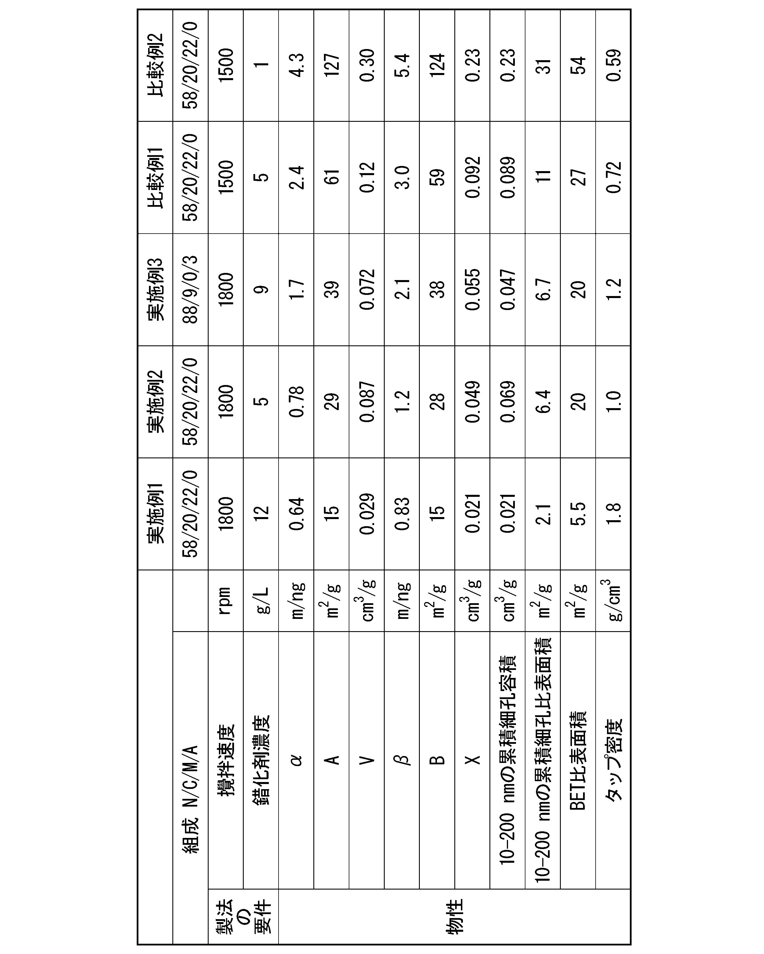
実施例1の前駆体と、水酸化リチウム粉末とを、前駆体中のNi、Co、及びMnに対する水酸化リチウム粉末中のLiのモル比が、Li/(Ni+Co+Mn)=1.03となる割合で秤量して混合し、混合物を得た。
その後、得られた混合物を、酸素雰囲気下、650℃で5時間焼成し、石臼式粉砕機により粉砕し、さらに酸素雰囲気化840℃で5時間焼成した。再度、石臼型粉砕機により粉砕することによりCAMを得た。組成分析を行い、組成式(I)に対応させたところ、a=0.06、x=0.19、y=0.21、M=Mnであった。
実施例2の前駆体を使用したこと以外は実施例4と同様にCAMを得た。組成分析を行い、組成式(I)に対応させたところ、a=0.05、x=0.20、y=0.22、M=Mnであった。
実施例3の前駆体と水酸化リチウム粉末とを、前駆体中のNi、Co、及びAlに対する水酸化リチウム粉末中のLiのモル比が、Li/(Ni+Co+Al)=1.03となる割合で秤量して混合したこと、2回目の焼成温度を770℃としたこと以外は実施例4と同様にCAMを得た。組成分析を行い、組成式(I)に対応させたところ、a=0.06、x=0.09、y=0.03、M=Alであった。
比較例1の前駆体を使用し、2回目の焼成温度を1000℃としたこと以外は実施例4と同様にCAMを得た。組成分析を行い、組成式(I)に対応させたところ、a=0.06、x=0.20、y=0.22、M=Mnであった。
比較例2の前駆体を使用したこと以外は実施例4と同様にCAMを得た。組成分析を行い、組成式(I)に対応させたところ、a=0.06、x=0.20、y=0.22、M=Mnであった。
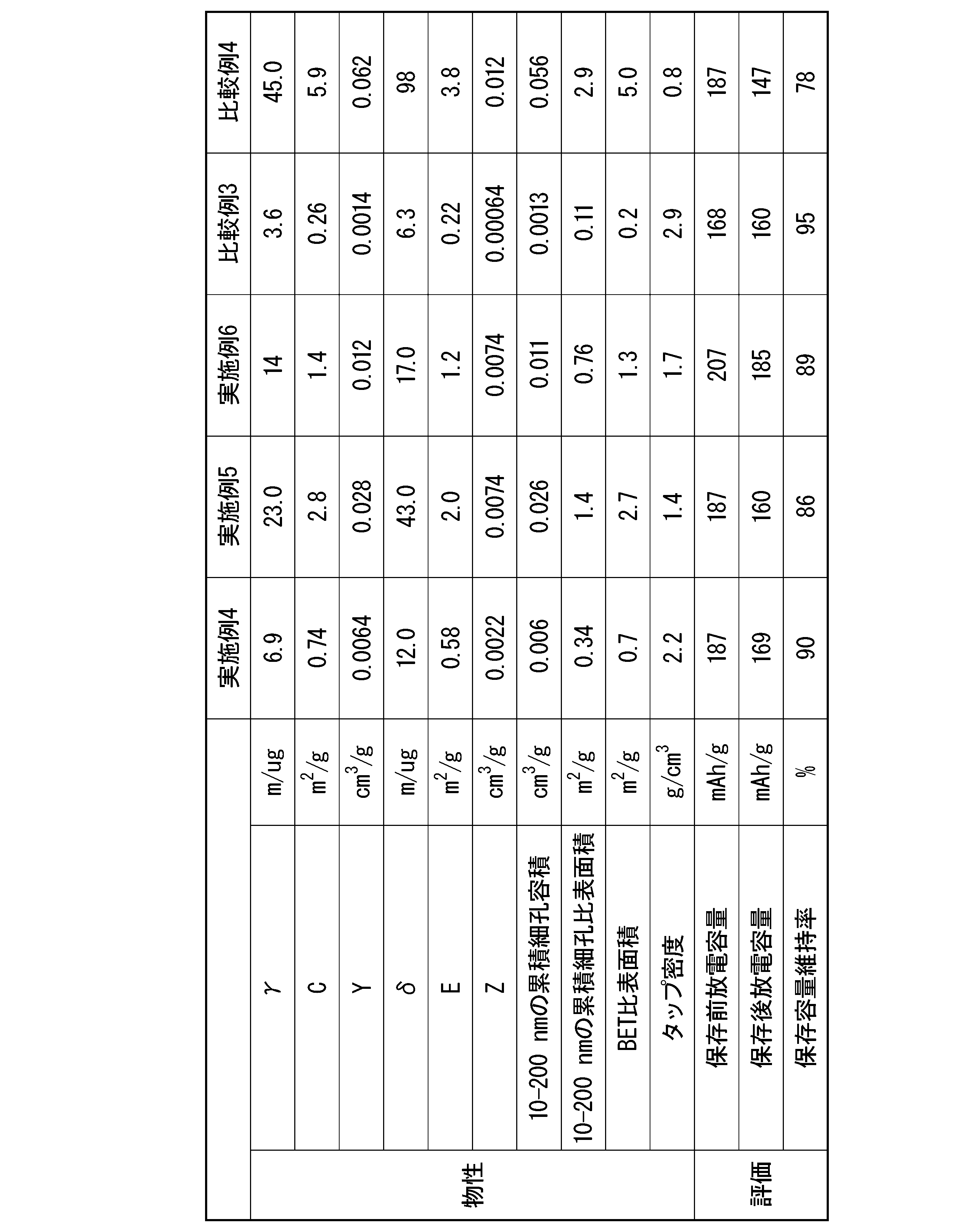
Claims (11)
- リチウム二次電池用正極活物質の前駆体であって、
少なくともNiを含み、下記式(1)より算出される値αが2.3m/ng以下である、前駆体。
α=A2/(4πV)÷1000 ・・・(1)
(式(1)中、Aは、液体窒素温度で測定された前記前駆体の窒素脱離等温線をBJH法で解析して得られる細孔比表面積のうち、細孔直径が2.6nm以上200nm以下の累積細孔比表面積(m2/g)である。
Vは、液体窒素温度で測定された前記前駆体の窒素脱離等温線をBJH法で解析して得られる細孔容積のうち、細孔直径が2.6nm以上200nm以下の累積細孔容積(cm3/g)である。) - 下記式(2)より算出される値βが2.8m/ng以下である、請求項1に記載の前駆体。
β=B2/(4πX)÷1000 ・・・(2)
(式(2)中、Bは、液体窒素温度で測定された前記前駆体の窒素脱離等温線をBJH法で解析して得られる細孔比表面積のうち、細孔直径が2.6nm以上50nm以下の累積細孔比表面積(m2/g)である。
Xは、液体窒素温度で測定された前記前駆体の窒素脱離等温線をBJH法で解析して得られる細孔容積のうち、細孔直径が2.6nm以上50nm以下の累積細孔容積(cm3/g)である。) - BET比表面積が1.0m2/g以上25m2/g以下である、請求項1又は2に記載の前駆体。
- タップ密度が0.8g/cm3以上2.7g/cm3以下である、請求項1~3のいずれか1項に記載の前駆体。
- 少なくともNiを含み、下記式(3)より算出される値γが4.0m/μg以上40.0m/μg以下である、リチウム二次電池用正極活物質。
γ=C2/(4πY) ・・・(3)
(式(3)中、Cは、液体窒素温度で測定された前記リチウム二次電池用正極活物質の窒素脱離等温線をBJH法で解析して得られる細孔比表面積のうち、細孔直径が2.6nm以上200nm以下の累積細孔比表面積(m2/g)である。
Yは、液体窒素温度で測定された前記リチウム二次電池用正極活物質の窒素脱離等温線をBJH法で解析して得られる細孔容積のうち、細孔直径が2.6nm以上200nm以下の累積細孔容積(cm3/g)である。) - 下記式(4)より算出される値δが10m/μg以上50m/μg以下である、請求項5に記載のリチウム二次電池用正極活物質。
δ=E2/(4πZ) ・・・(4)
(式(4)中、Eは、液体窒素温度で測定された前記リチウム二次電池用正極活物質の窒素脱離等温線をBJH法で解析して得られる細孔比表面積のうち、細孔直径が2.6nm以上50nm以下の累積細孔比表面積(m2/g)である。
Zは、液体窒素温度で測定された前記リチウム二次電池用正極活物質の窒素脱離等温線をBJH法で解析して得られる細孔容積のうち、細孔直径が2.6nm以上50nm以下の累積細孔容積(cm3/g)である。) - 下記組成式(I)で表される請求項5又は6に記載のリチウム二次電池用正極活物質。 Li[Lia(Ni1-x-yCoxMy)1-a]O2…(I)
(ただし、式(I)において、MはFe、Cu、Mg、Mn、Al、W、B、Mo、Zn、Sn、Zr、Ga、La、Ti、Nb及びVからなる群より選ばれる少なくとも1種の元素であり、-0.10≦a≦0.30、0≦x≦0.45、及び0≦y≦0.45を満たす。) - BET比表面積が0.3m2/g以上4.0m2/g以下である、請求項5~7のいずれか1項に記載のリチウム二次電池用正極活物質。
- タップ密度が1.0g/cm3以上2.8g/cm3以下である請求項5~8のいずれか1項に記載のリチウム二次電池用正極活物質。
- 請求項5~9のいずれか1項に記載のリチウム二次電池用正極活物質を含むリチウム二次電池用正極。
- 請求項10に記載のリチウム二次電池用正極を有するリチウム二次電池。
Priority Applications (4)
| Application Number | Priority Date | Filing Date | Title |
|---|---|---|---|
| KR1020237015763A KR20230108268A (ko) | 2020-11-19 | 2021-11-18 | 전구체, 리튬 이차 전지용 정극 활물질, 리튬 이차 전지용 정극 및 리튬 이차 전지 |
| EP21894733.1A EP4249437A4 (en) | 2020-11-19 | 2021-11-18 | PRECURSOR, POSITIVE ELECTRODE ACTIVE MATERIAL FOR LITHIUM SECONDARY BATTERY, POSITIVE ELECTRODE FOR LITHIUM SECONDARY BATTERY AND LITHIUM SECONDARY BATTERY |
| US18/253,309 US20240030430A1 (en) | 2020-11-19 | 2021-11-18 | Precursor, positive electrode active material for lithium secondary battery, positive electrode for lithium secondary battery, and lithium secondary battery |
| CN202180076368.4A CN116490468B (zh) | 2020-11-19 | 2021-11-18 | 前体、锂二次电池用正极活性物质、锂二次电池用正极及锂二次电池 |
Applications Claiming Priority (2)
| Application Number | Priority Date | Filing Date | Title |
|---|---|---|---|
| JP2020192685A JP6930015B1 (ja) | 2020-11-19 | 2020-11-19 | 前駆体、リチウム二次電池用正極活物質、リチウム二次電池用正極及びリチウム二次電池 |
| JP2020-192685 | 2020-11-19 |
Publications (1)
| Publication Number | Publication Date |
|---|---|
| WO2022107861A1 true WO2022107861A1 (ja) | 2022-05-27 |
Family
ID=77456360
Family Applications (1)
| Application Number | Title | Priority Date | Filing Date |
|---|---|---|---|
| PCT/JP2021/042492 Ceased WO2022107861A1 (ja) | 2020-11-19 | 2021-11-18 | 前駆体、リチウム二次電池用正極活物質、リチウム二次電池用正極及びリチウム二次電池 |
Country Status (6)
| Country | Link |
|---|---|
| US (1) | US20240030430A1 (ja) |
| EP (1) | EP4249437A4 (ja) |
| JP (1) | JP6930015B1 (ja) |
| KR (1) | KR20230108268A (ja) |
| CN (1) | CN116490468B (ja) |
| WO (1) | WO2022107861A1 (ja) |
Families Citing this family (3)
| Publication number | Priority date | Publication date | Assignee | Title |
|---|---|---|---|---|
| JP2023078887A (ja) * | 2021-11-26 | 2023-06-07 | 株式会社田中化学研究所 | 遷移金属含有水酸化物、遷移金属含有水酸化物を前駆体とした正極活物質 |
| JP2023078888A (ja) * | 2021-11-26 | 2023-06-07 | 株式会社田中化学研究所 | 遷移金属含有水酸化物、遷移金属含有水酸化物を前駆体とした正極活物質、遷移金属含有水酸化物の製造方法 |
| JP7441998B1 (ja) * | 2023-05-31 | 2024-03-01 | 住友化学株式会社 | リチウム金属複合酸化物、リチウム二次電池用正極活物質、リチウム二次電池用正極、および、リチウム二次電池 |
Citations (16)
| Publication number | Priority date | Publication date | Assignee | Title |
|---|---|---|---|---|
| JP2000030686A (ja) | 1998-04-27 | 2000-01-28 | Sumitomo Chem Co Ltd | 非水電解質電池セパレ―タ―とリチウム二次電池 |
| WO2002086993A1 (en) * | 2001-04-20 | 2002-10-31 | Yuasa Corporation | Anode active matter and production method therefor, non- aqueous electrolyte secondary battery-use anode, and non-aqueous electrolyte secondary battery |
| JP2004095400A (ja) | 2002-08-30 | 2004-03-25 | Nissan Motor Co Ltd | バイポーラ電池とその制御方法 |
| JP2005123179A (ja) * | 2003-09-26 | 2005-05-12 | Mitsubishi Chemicals Corp | リチウム二次電池正極材用リチウム複合酸化物粒子、並びにそれを用いたリチウム二次電池用正極及びリチウム二次電池 |
| US20090111025A1 (en) | 2004-12-22 | 2009-04-30 | Lg Chem, Ltd. | Organic/inorganic composite microporous membrane and electrochemical device prepared thereby |
| US20120251871A1 (en) | 2011-03-29 | 2012-10-04 | Tohoku University | All-solid-state battery |
| WO2014203814A1 (ja) * | 2013-06-17 | 2014-12-24 | 住友金属鉱山株式会社 | ニッケルコバルトマンガン複合水酸化物及びその製造方法 |
| US20160233510A1 (en) | 2013-11-08 | 2016-08-11 | Hitachi, Ltd. | All-solid state battery, electrode for all-solid state battery, and method of manufacturing the same |
| US20180159169A1 (en) | 2015-10-30 | 2018-06-07 | Lg Chem, Ltd. | Polymer electrolyte having multi-layer structure, and all-solid battery comprising same |
| JP2018098218A (ja) * | 2016-12-07 | 2018-06-21 | 住友化学株式会社 | リチウム二次電池用正極活物質、リチウム二次電池用正極及びリチウム二次電池 |
| JP2018170240A (ja) * | 2017-03-30 | 2018-11-01 | 三洋電機株式会社 | 非水電解質二次電池 |
| JP2018206775A (ja) * | 2017-05-31 | 2018-12-27 | 住友化学株式会社 | リチウム二次電池用正極活物質、リチウム二次電池用正極及びリチウム二次電池 |
| WO2019098384A1 (ja) | 2017-11-20 | 2019-05-23 | 住友化学株式会社 | リチウム二次電池用正極活物質、リチウム二次電池用正極及びリチウム二次電池 |
| US20200259213A1 (en) | 2017-11-13 | 2020-08-13 | Murata Manufacturing Co., Ltd. | All-solid-state battery |
| WO2020208872A1 (ja) | 2019-04-12 | 2020-10-15 | 住友化学株式会社 | リチウム金属複合酸化物粉末及びリチウム二次電池用正極活物質 |
| JP2020192685A (ja) | 2019-05-24 | 2020-12-03 | 有限会社藤村産業 | 図形表示パネル |
Family Cites Families (10)
| Publication number | Priority date | Publication date | Assignee | Title |
|---|---|---|---|---|
| CN100492728C (zh) * | 2003-09-26 | 2009-05-27 | 三菱化学株式会社 | 用于锂二次电池正极材料的锂复合氧化物颗粒、使用该颗粒的锂二次电池正极以及锂二次电池 |
| US9570741B2 (en) * | 2012-03-21 | 2017-02-14 | Duracell U.S. Operations, Inc. | Metal-doped nickel oxide active materials |
| US9028564B2 (en) * | 2012-03-21 | 2015-05-12 | The Gillette Company | Methods of making metal-doped nickel oxide active materials |
| JP6252384B2 (ja) * | 2014-06-27 | 2017-12-27 | 住友金属鉱山株式会社 | ニッケル複合水酸化物及びその製造方法、正極活物質及びその製造方法、並びに非水系電解質二次電池 |
| JP6252383B2 (ja) * | 2014-06-27 | 2017-12-27 | 住友金属鉱山株式会社 | マンガンコバルト複合水酸化物及びその製造方法、正極活物質及びその製造方法、並びに非水系電解質二次電池 |
| JP6388978B1 (ja) * | 2017-03-31 | 2018-09-12 | 住友化学株式会社 | リチウム二次電池用正極活物質、リチウム二次電池用正極及びリチウム二次電池 |
| JP6583359B2 (ja) | 2017-07-27 | 2019-10-02 | 住友金属鉱山株式会社 | ニッケルコバルトマンガン複合水酸化物 |
| CN112514130A (zh) | 2018-07-30 | 2021-03-16 | 株式会社村田制作所 | 锂离子二次电池 |
| US20220194814A1 (en) * | 2019-04-10 | 2022-06-23 | Basf Se | Process for precipitating a mixed hydroxide, and cathode active materials made from such hydroxide |
| KR102774021B1 (ko) * | 2019-09-17 | 2025-02-26 | 스미토모 긴조쿠 고잔 가부시키가이샤 | 리튬 이온 이차전지용 양극 활물질 및 리튬 이온 이차전지 |
-
2020
- 2020-11-19 JP JP2020192685A patent/JP6930015B1/ja active Active
-
2021
- 2021-11-18 US US18/253,309 patent/US20240030430A1/en active Pending
- 2021-11-18 CN CN202180076368.4A patent/CN116490468B/zh active Active
- 2021-11-18 EP EP21894733.1A patent/EP4249437A4/en active Pending
- 2021-11-18 KR KR1020237015763A patent/KR20230108268A/ko active Pending
- 2021-11-18 WO PCT/JP2021/042492 patent/WO2022107861A1/ja not_active Ceased
Patent Citations (17)
| Publication number | Priority date | Publication date | Assignee | Title |
|---|---|---|---|---|
| JP2000030686A (ja) | 1998-04-27 | 2000-01-28 | Sumitomo Chem Co Ltd | 非水電解質電池セパレ―タ―とリチウム二次電池 |
| WO2002086993A1 (en) * | 2001-04-20 | 2002-10-31 | Yuasa Corporation | Anode active matter and production method therefor, non- aqueous electrolyte secondary battery-use anode, and non-aqueous electrolyte secondary battery |
| JP2004095400A (ja) | 2002-08-30 | 2004-03-25 | Nissan Motor Co Ltd | バイポーラ電池とその制御方法 |
| JP2005123179A (ja) * | 2003-09-26 | 2005-05-12 | Mitsubishi Chemicals Corp | リチウム二次電池正極材用リチウム複合酸化物粒子、並びにそれを用いたリチウム二次電池用正極及びリチウム二次電池 |
| US20090111025A1 (en) | 2004-12-22 | 2009-04-30 | Lg Chem, Ltd. | Organic/inorganic composite microporous membrane and electrochemical device prepared thereby |
| US20120251871A1 (en) | 2011-03-29 | 2012-10-04 | Tohoku University | All-solid-state battery |
| WO2014203814A1 (ja) * | 2013-06-17 | 2014-12-24 | 住友金属鉱山株式会社 | ニッケルコバルトマンガン複合水酸化物及びその製造方法 |
| US20160233510A1 (en) | 2013-11-08 | 2016-08-11 | Hitachi, Ltd. | All-solid state battery, electrode for all-solid state battery, and method of manufacturing the same |
| US20180159169A1 (en) | 2015-10-30 | 2018-06-07 | Lg Chem, Ltd. | Polymer electrolyte having multi-layer structure, and all-solid battery comprising same |
| JP2018098218A (ja) * | 2016-12-07 | 2018-06-21 | 住友化学株式会社 | リチウム二次電池用正極活物質、リチウム二次電池用正極及びリチウム二次電池 |
| JP2018170240A (ja) * | 2017-03-30 | 2018-11-01 | 三洋電機株式会社 | 非水電解質二次電池 |
| JP2018206775A (ja) * | 2017-05-31 | 2018-12-27 | 住友化学株式会社 | リチウム二次電池用正極活物質、リチウム二次電池用正極及びリチウム二次電池 |
| US20200259213A1 (en) | 2017-11-13 | 2020-08-13 | Murata Manufacturing Co., Ltd. | All-solid-state battery |
| WO2019098384A1 (ja) | 2017-11-20 | 2019-05-23 | 住友化学株式会社 | リチウム二次電池用正極活物質、リチウム二次電池用正極及びリチウム二次電池 |
| US20200274158A1 (en) | 2017-11-20 | 2020-08-27 | Sumitomo Chemical Company, Limited | Positive-electrode active material for lithium secondary battery, positive electrode for lithium secondary battery, and lithium secondary battery |
| WO2020208872A1 (ja) | 2019-04-12 | 2020-10-15 | 住友化学株式会社 | リチウム金属複合酸化物粉末及びリチウム二次電池用正極活物質 |
| JP2020192685A (ja) | 2019-05-24 | 2020-12-03 | 有限会社藤村産業 | 図形表示パネル |
Non-Patent Citations (1)
| Title |
|---|
| See also references of EP4249437A4 |
Also Published As
| Publication number | Publication date |
|---|---|
| CN116490468A (zh) | 2023-07-25 |
| KR20230108268A (ko) | 2023-07-18 |
| JP2022081251A (ja) | 2022-05-31 |
| CN116490468B (zh) | 2024-08-13 |
| JP6930015B1 (ja) | 2021-09-01 |
| EP4249437A1 (en) | 2023-09-27 |
| EP4249437A4 (en) | 2025-03-19 |
| US20240030430A1 (en) | 2024-01-25 |
Similar Documents
| Publication | Publication Date | Title |
|---|---|---|
| US12015153B2 (en) | Method of producing cathode active material, and method of producing lithium ion battery | |
| WO2021145420A1 (ja) | 全固体リチウムイオン電池用正極活物質、電極および全固体リチウムイオン電池 | |
| JP7121165B1 (ja) | リチウム二次電池用正極活物質、リチウム二次電池用正極及びリチウム二次電池 | |
| CN113677627A (zh) | 锂复合金属氧化物粉末以及锂二次电池用正极活性物质 | |
| WO2021117890A1 (ja) | リチウム金属複合酸化物、リチウム二次電池用正極活物質、リチウム二次電池用正極及びリチウム二次電池 | |
| WO2022107861A1 (ja) | 前駆体、リチウム二次電池用正極活物質、リチウム二次電池用正極及びリチウム二次電池 | |
| WO2022009843A1 (ja) | リチウム二次電池正極活物質用前駆体、リチウム金属複合酸化物、リチウム二次電池用正極活物質、リチウム二次電池用正極及びリチウム二次電池 | |
| JP2016081716A (ja) | リチウムイオン二次電池用正極活物質及びその製造方法並びにリチウムイオン二次電池 | |
| US20230022902A1 (en) | Lithium metal composite oxide powder, positive electrode active material for lithium secondary battery, positive electrode for lithium secondary battery, and lithium secondary battery | |
| WO2022044720A1 (ja) | リチウム二次電池用正極活物質、リチウム二次電池用正極及びリチウム二次電池 | |
| CN111279529A (zh) | 锂复合金属化合物、锂二次电池用正极活性物质、锂二次电池用正极以及锂二次电池 | |
| WO2021172509A1 (ja) | リチウム金属複合酸化物、リチウム二次電池用正極活物質、リチウム二次電池用正極及びリチウム二次電池 | |
| JP2012116746A (ja) | スピネル型リチウム・マンガン複合酸化物 | |
| JP7181982B1 (ja) | 前駆体粉末、正極活物質粉末、正極活物質粉末の製造方法、正極及びリチウム二次電池 | |
| JP7116267B1 (ja) | 金属複合化合物、リチウム金属複合酸化物の製造方法及び金属複合化合物の製造方法 | |
| WO2022004323A1 (ja) | リチウム二次電池正極活物質用前駆体及びリチウム二次電池正極活物質の製造方法 | |
| WO2022050314A1 (ja) | リチウム金属複合酸化物、リチウム二次電池用正極及びリチウム二次電池 | |
| JP7219802B1 (ja) | リチウム金属複合酸化物、リチウム二次電池用正極活物質、リチウム二次電池用正極及びリチウム二次電池 | |
| JP7244615B1 (ja) | リチウム二次電池用正極活物質、リチウム二次電池用正極及びリチウム二次電池 | |
| Park et al. | The effects of sulfur doping on the performance of O3-Li0. 7 [Li1/12Ni1/12Mn5/6] O2 powder | |
| US20230069426A1 (en) | Lithium metal composite oxide, positive electrode active material for lithium secondary battery, positive electrode for lithium secondary battery, and lithium secondary battery | |
| JP2023101923A (ja) | リチウム金属複合酸化物粉末、固体二次電池用正極活物質、固体二次電池用正極及び固体二次電池 | |
| WO2024218923A1 (ja) | リチウム金属複合酸化物粉末、固体二次電池用正極活物質、固体二次電池用正極及び固体二次電池 | |
| JP2023101586A (ja) | リチウム二次電池用正極活物質、リチウム二次電池用正極及びリチウム二次電池 | |
| JP2023142148A (ja) | リチウム二次電池用正極活物質、リチウム二次電池用正極、リチウム二次電池及びリチウム二次電池用正極活物質の製造方法 |
Legal Events
| Date | Code | Title | Description |
|---|---|---|---|
| 121 | Ep: the epo has been informed by wipo that ep was designated in this application |
Ref document number: 21894733 Country of ref document: EP Kind code of ref document: A1 |
|
| WWE | Wipo information: entry into national phase |
Ref document number: 202180076368.4 Country of ref document: CN |
|
| WWE | Wipo information: entry into national phase |
Ref document number: 18253309 Country of ref document: US |
|
| NENP | Non-entry into the national phase |
Ref country code: DE |
|
| ENP | Entry into the national phase |
Ref document number: 2021894733 Country of ref document: EP Effective date: 20230619 |