WO2022113452A1 - 車両性能評価システム、車両性能評価方法及び車両性能評価プログラム - Google Patents
車両性能評価システム、車両性能評価方法及び車両性能評価プログラム Download PDFInfo
- Publication number
- WO2022113452A1 WO2022113452A1 PCT/JP2021/031581 JP2021031581W WO2022113452A1 WO 2022113452 A1 WO2022113452 A1 WO 2022113452A1 JP 2021031581 W JP2021031581 W JP 2021031581W WO 2022113452 A1 WO2022113452 A1 WO 2022113452A1
- Authority
- WO
- WIPO (PCT)
- Prior art keywords
- test
- vehicle
- unit
- conditions
- test unit
- Prior art date
- Legal status (The legal status is an assumption and is not a legal conclusion. Google has not performed a legal analysis and makes no representation as to the accuracy of the status listed.)
- Ceased
Links
Images


Classifications
-
- G—PHYSICS
- G01—MEASURING; TESTING
- G01M—TESTING STATIC OR DYNAMIC BALANCE OF MACHINES OR STRUCTURES; TESTING OF STRUCTURES OR APPARATUS, NOT OTHERWISE PROVIDED FOR
- G01M17/00—Testing of vehicles
- G01M17/007—Wheeled or endless-tracked vehicles
-
- G—PHYSICS
- G07—CHECKING-DEVICES
- G07C—TIME OR ATTENDANCE REGISTERS; REGISTERING OR INDICATING THE WORKING OF MACHINES; GENERATING RANDOM NUMBERS; VOTING OR LOTTERY APPARATUS; ARRANGEMENTS, SYSTEMS OR APPARATUS FOR CHECKING NOT PROVIDED FOR ELSEWHERE
- G07C5/00—Registering or indicating the working of vehicles
- G07C5/08—Registering or indicating performance data other than driving, working, idle, or waiting time, with or without registering driving, working, idle or waiting time
- G07C5/0808—Diagnosing performance data
-
- G—PHYSICS
- G01—MEASURING; TESTING
- G01S—RADIO DIRECTION-FINDING; RADIO NAVIGATION; DETERMINING DISTANCE OR VELOCITY BY USE OF RADIO WAVES; LOCATING OR PRESENCE-DETECTING BY USE OF THE REFLECTION OR RERADIATION OF RADIO WAVES; ANALOGOUS ARRANGEMENTS USING OTHER WAVES
- G01S13/00—Systems using the reflection or reradiation of radio waves, e.g. radar systems; Analogous systems using reflection or reradiation of waves whose nature or wavelength is irrelevant or unspecified
- G01S13/88—Radar or analogous systems specially adapted for specific applications
- G01S13/93—Radar or analogous systems specially adapted for specific applications for anti-collision purposes
- G01S13/931—Radar or analogous systems specially adapted for specific applications for anti-collision purposes of land vehicles
-
- G—PHYSICS
- G01—MEASURING; TESTING
- G01S—RADIO DIRECTION-FINDING; RADIO NAVIGATION; DETERMINING DISTANCE OR VELOCITY BY USE OF RADIO WAVES; LOCATING OR PRESENCE-DETECTING BY USE OF THE REFLECTION OR RERADIATION OF RADIO WAVES; ANALOGOUS ARRANGEMENTS USING OTHER WAVES
- G01S7/00—Details of systems according to groups G01S13/00, G01S15/00, G01S17/00
- G01S7/02—Details of systems according to groups G01S13/00, G01S15/00, G01S17/00 of systems according to group G01S13/00
- G01S7/40—Means for monitoring or calibrating
-
- G—PHYSICS
- G01—MEASURING; TESTING
- G01S—RADIO DIRECTION-FINDING; RADIO NAVIGATION; DETERMINING DISTANCE OR VELOCITY BY USE OF RADIO WAVES; LOCATING OR PRESENCE-DETECTING BY USE OF THE REFLECTION OR RERADIATION OF RADIO WAVES; ANALOGOUS ARRANGEMENTS USING OTHER WAVES
- G01S13/00—Systems using the reflection or reradiation of radio waves, e.g. radar systems; Analogous systems using reflection or reradiation of waves whose nature or wavelength is irrelevant or unspecified
- G01S13/88—Radar or analogous systems specially adapted for specific applications
- G01S13/93—Radar or analogous systems specially adapted for specific applications for anti-collision purposes
- G01S13/931—Radar or analogous systems specially adapted for specific applications for anti-collision purposes of land vehicles
- G01S2013/9323—Alternative operation using light waves
Definitions
- This disclosure relates to a vehicle performance evaluation system, a vehicle performance evaluation method, and a vehicle performance evaluation program.
- Vehicle test equipment includes a collision test device that confirms safety, a test course that confirms driving performance, and the like.
- Patent Document 1 describes an invention of a test system and a test method for carrying out an operation test of a safe driving support application by simulating the behavior of a peripheral vehicle under various road surface conditions existing in a real environment.
- a vehicle equipped with a driving support function detects a driving state, controls the behavior of the vehicle based on the result, and outputs information on driving support.
- the traveling state includes the state of the own vehicle and surrounding traffic participants (other vehicles, motorcycles, bicycles, pedestrians, running paths, signs, structures, etc.). Therefore, it is necessary to evaluate whether the driving state is properly detected and whether the control suitable for the detected running state is performed.
- Patent Document 1 The simulation described in Patent Document 1 can be analyzed by simulation, but an actual test is also required for vehicle design. Therefore, it is necessary to devise in order to effectively utilize the simulation results.
- the present disclosure provides a vehicle performance evaluation system, a vehicle performance evaluation method, and a vehicle performance evaluation program that can evaluate the performance of a vehicle in more detail.
- the vehicle performance evaluation system of the present disclosure includes a first test unit for testing the performance of the vehicle, at least one second test unit for testing the performance of the vehicle by a method different from the first test unit, and the first test unit.
- the test result of the test unit and the test result of the second test unit are composed of a management unit that manages the test result.
- the management unit includes a test condition determination device that performs adjustment processing based on test conditions including meteorological conditions, a data processing device that outputs evaluations, and a database, and the first test unit is around the vehicle to be tested.
- An environment reproduction mechanism that reproduces the environment, a traveling condition reproduction mechanism that moves relative to the test target vehicle and reproduces the traveling state of the vehicle, an environment reproduction mechanism, and a traveling condition reproduction mechanism are covered with the vehicle. It is equipped with a building whose surroundings are indoor spaces. Relative movement may be the movement of surrounding traffic participants or the movement of the vehicle under test.
- the vehicle performance evaluation method of the present disclosure includes a step of acquiring the test conditions of the test executed in the first test unit and the performance of the vehicle as the test result, and the performance of the vehicle by a method different from that of the first test unit.
- the step of acquiring the test conditions of the test performed in at least one second test unit to be tested and the vehicle performance of the test result, the test result of the first test unit, and the test result of the second test unit are shown in the weather.
- the first test unit includes an environment reproduction mechanism that reproduces the environment around the test target vehicle and the test target vehicle, including a step of performing adjustment processing based on the test conditions including conditions and outputting an evaluation. It is provided with a traveling condition reproduction mechanism that reproduces the traveling state of the vehicle by moving relative to the vehicle, and a building that covers the traveling condition reproduction mechanism and the environment reproduction mechanism and has an indoor space around the test stage.
- the vehicle performance evaluation program of the present disclosure includes an environment reproduction mechanism that reproduces the environment around the test target vehicle, a traveling condition reproduction mechanism that moves relative to the test target vehicle and reproduces the running state of the vehicle, and the above-mentioned.
- the performance of the vehicle can be evaluated in more detail.
- FIG. 1 is a block diagram showing a schematic configuration of a vehicle performance evaluation system according to an embodiment.
- FIG. 2 is a block diagram showing a functional configuration of the vehicle to be tested.
- FIG. 3 is an explanatory diagram for explaining the sensor function of the vehicle to be tested.
- FIG. 4 is a block diagram showing a schematic configuration of the indoor test unit.
- FIG. 5 is a front view showing a schematic configuration of an indoor test unit, and is a case of relative movement in which surrounding traffic participants move.
- FIG. 6 is a side view showing a schematic configuration of the indoor test unit, and is a case of relative movement in which surrounding traffic participants move.
- FIG. 7 is a plan view showing an outline of the vehicle driving test installation, and is a case of relative movement in which surrounding traffic participants move.
- FIG. 1 is a block diagram showing a schematic configuration of a vehicle performance evaluation system according to an embodiment.
- FIG. 2 is a block diagram showing a functional configuration of the vehicle to be tested.
- FIG. 3 is an
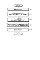
- FIG. 8 is a flowchart showing an example of processing of the vehicle performance evaluation system.
- FIG. 9 is a flowchart showing an example of processing of the data processing apparatus.
- FIG. 10 is a flowchart showing an example of processing of the test condition determining device.
- FIG. 11 is an explanatory diagram for explaining an example of the evaluation result of the vehicle performance evaluation system.
- FIG. 12 is a schematic diagram when the test target vehicle of the indoor test unit moves.
- FIG. 13 is a schematic diagram when the test target vehicle of the indoor test unit moves.
- FIG. 14 is a schematic diagram when the test target vehicle of the indoor test unit moves.
- FIG. 15 is a schematic diagram when the test target vehicle of the indoor test unit moves.
- FIG. 16 is a schematic diagram when the test target vehicle of the indoor test unit moves.
- FIG. 17 is a schematic diagram when the test target vehicle of the indoor test unit moves.
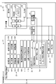
- FIG. 1 is a block diagram showing a schematic configuration of the vehicle performance evaluation system 1 according to the embodiment.
- the vehicle performance evaluation system 1 includes a management unit 2, a first test unit 3, and a second test unit 5.
- the first test unit 3 includes an indoor test unit 4.
- the second test unit 5 includes a simulation unit 6 and an outdoor test unit 7.
- the first test unit 3 of the present embodiment is one indoor test unit 4, but may include a plurality of indoor test units 4.
- the second test unit 5 of the present embodiment includes a simulation unit 6 and an outdoor test unit 7, but may include only one of the simulation unit 6, the simulation unit 6, and the outdoor test unit 7. May be provided in a plurality of each.
- the vehicle performance evaluation system 1 tests the test target vehicle 8 and evaluates the performance of the test target vehicle 8.
- the test target vehicle 8 may be one or a plurality of vehicles having the same function. Further, the test target vehicle 8 to be tested by the simulation unit 6 may have a control function of the test target vehicle 8, and does not need to have a vehicle body, tires, a prime mover, a sensor, or the like.
- the performance of the test target vehicle 8 is the performance during traveling.
- the vehicle performance evaluation system 1 evaluates the performance of driving support functions including automatic driving.
- the driving support function includes an automatic driving function that allows the passenger to drive the vehicle without any operation, a function that detects the surrounding situation, provides warnings and guidance, and assists the passenger in driving.
- the automatic driving function includes a function corresponding to various levels of automatic driving.
- the management unit 2 manages the tests executed by a plurality of units to be tested.
- the management unit 2 acquires and stores information on the test results of each unit to be tested.
- the management unit 2 analyzes the test results and outputs the analysis results. Further, the management unit 2 determines the test conditions to be executed in each unit, that is, the test conditions.
- the management unit 2 includes a test condition determination device 50, a data processing device 52, a database 54, an input unit 56, and an output unit 58.
- the management unit 2 may be a single personal computer, but may be configured by connecting a plurality of arithmetic units via a wired or wireless network.
- the management unit 2 may include a plurality of input units 56 and output units 58.
- an input unit 56 and an output unit 58 may be provided for each of the test condition determination device 50, the data processing device 52, and the database 54.
- the input unit 56 is a device that receives user input, and is, for example, a mouse, a keyboard, a touch panel, or the like.
- the output unit 58 is a device that displays calculation results of the test condition determination device 50 and the data processing device 52, database data, input contents from the user, and the like.
- the output unit 58 is, for example, a display or a touch panel.
- the test condition determination device 50 determines the test conditions of the test target vehicle 8 to be executed by the indoor test unit 4, the simulation unit 6, and the outdoor test unit 7.
- the test condition determination device 50 includes an arithmetic unit, that is, a CPU (Central Processing Unit), and a storage device, that is, a memory that stores arithmetic contents, program information, and the like.
- the memory includes, for example, at least one of a RAM (Random Access Memory), a ROM (Read Only Memory), and an external storage device such as an HDD (Hard Disk Drive).
- the test condition determination device 50 includes an evaluation acquisition unit 302, a unit information acquisition unit 304, and a test condition calculation unit 306.
- the evaluation acquisition unit 302 acquires the test conditions and test results of the test target vehicle 8 executed by the indoor test unit 4, the simulation unit 6, and the outdoor test unit 7.
- the test conditions include vehicle information, running conditions, environmental conditions, and weather conditions of the vehicle 8 to be tested.
- the traveling conditions are the traveling speed of the vehicle 8 to be tested, the steering angle, the output of the drive source, the braking operation, and the like.
- the environmental conditions include temperature, brightness, position of the sun, road surface conditions, surrounding conditions when the vehicle 8 to be tested is running, and the like.
- the road surface condition is whether the traveling road surface is dry, wet, frozen, snowy, paved, or the like.
- the surrounding conditions of the test target vehicle 8 when traveling are the presence / absence of pedestrians, cyclists, oncoming vehicles, etc., position, moving direction, moving speed, position of road signs, number of lanes, and the like. ..
- the weather conditions are sunny, cloudy, rainy, snowy, hail, fog, sandstorm and other weather conditions, wind direction, wind speed and the like. In the case of rain, etc., the amount of rainfall is also included in the conditions.
- the test results include information acquired by the test vehicle 8 during the test, controlled controls, and the like.
- the unit information acquisition unit 304 acquires information on the indoor test unit 4, the simulation unit 6, and the outdoor test unit 7. Specifically, the unit information acquisition unit 304 is a device that detects test conditions that can be executed in each of the indoor test unit 4, the simulation unit 6, and the outdoor test unit 7, and test results and environmental conditions in each test unit. Get performance information.
- the test condition calculation unit 306 calculates the test conditions to be executed based on the information of the executed test acquired by the evaluation acquisition unit 302 and the information of each unit acquired by the unit information acquisition unit 304.
- the data processing device 52 processes the test results based on the test results executed in each unit and the conditions of the test, and evaluates the test results.
- the data processing device 52 includes an arithmetic unit, that is, a CPU (Central Processing Unit), and a storage device, that is, a memory that stores arithmetic contents, program information, and the like.
- the memory includes, for example, at least one of a RAM (Random Access Memory), a ROM (Read Only Memory), and an external storage device such as an HDD (Hard Disk Drive).
- the data processing device 52 includes a test result acquisition unit 312, a parameter conversion unit 314, a test result integration unit 316, and an evaluation unit 318.
- the test result acquisition unit 312 acquires the test conditions and test results of the test target vehicle 8 executed by the indoor test unit 4, the simulation unit 6, and the outdoor test unit 7.
- the test conditions include vehicle information, running conditions, environmental conditions, and weather conditions of the vehicle 8 to be tested.
- the parameter conversion unit 314 converts the test conditions of the test executed in each unit into a state that can be evaluated with the same parameters.
- the parameter meter is a condition that can be detected or set at the time of the test of the test target vehicle 8, and is a condition selected from the weather condition, the environmental condition, and the traveling condition. For example, it is possible to use the amount of rainfall as a parameter while keeping the environmental conditions constant, or the condition of the road surface (wet or dry, the degree of wetness, the coefficient of road friction) as a parameter while keeping the driving conditions constant. can.
- the parameter conversion unit 314 arranges the parameters based on the test conditions so that the tests performed in different units can be evaluated with the same parameters.
- the test result integration unit 316 integrates the results of tests executed in different units based on the results converted by the parameter conversion unit 314. This makes it possible to compare the test results of a plurality of units executed on the test target vehicle 8.
- the evaluation unit 318 evaluates the performance of the test target vehicle 8 based on the test results integrated by the test result integration unit 316. As a result of the evaluation, the evaluation unit 318 may create and output a graph based on the parameters integrated by the test result integration unit 316.
- the database 54 stores and manages the program that executes the processing of the management unit 2 and the data related to various tests acquired by the vehicle performance evaluation system 1.
- the database 54 includes an arithmetic unit, that is, a CPU (Central Processing Unit), and a storage device, that is, a memory that stores arithmetic contents, program information, and the like.
- the memory includes, for example, at least one of a RAM (Random Access Memory), a ROM (Read Only Memory), and an external storage device such as an HDD (Hard Disk Drive).
- the database 54 may not include an arithmetic unit but only a storage device, and data processing (writing, reading) may be performed by the test condition determining device 50 and the data processing device 52.
- the database 54 is provided, but the management unit 2 may store various data in the storage devices of the test condition determination device 50 and the data processing device 52.
- the database 54 includes a performance test program 322, a test condition database 324, a test result database 326, and an evaluation database 328.
- the performance test program 322 is a program for executing various processes executed by the vehicle performance evaluation system 1 and the management unit 2.
- the performance test program 322 is, for example, a program that executes the processing of the test condition determination device 50 and the data processing device 52.
- the vehicle performance evaluation system 1 may include a program for executing a test in the indoor test unit 4, the simulation unit 6, and the outdoor test unit 7 in the performance test program 322, or may be another program.
- the performance test program 322 does not have to be one program, but may be a combination of a plurality of programs.
- the test condition database 324 is data on the test conditions executed by the indoor test unit 4, the simulation unit 6, and the outdoor test unit 7.
- the test condition database 324 includes information on the range of test conditions that can be executed by the indoor test unit 4 and the simulation unit 6, and information for calculating the test conditions based on the results acquired by the outdoor test unit 7.
- the test condition database 324 includes data in which information on the test conditions of each test executed in the indoor test unit 4, the simulation unit 6, and the outdoor test unit 7 is associated with the test results.
- the test result database 326 is data of test results executed and acquired by the indoor test unit 4, the simulation unit 6, and the outdoor test unit 7.
- the test result includes data acquired from the test target vehicle 8 in the executed test, data acquired for confirming the test conditions and the like.
- the data acquired from the test target vehicle 8 includes the detection of the sensor mounted on the test target vehicle 8 and the processing result calculated by the control unit of the test target vehicle 8.
- the evaluation database 328 is data of templates such as various processing conditions and thresholds used by the evaluation unit 318 to execute the evaluation, and graphs and tables for outputting the evaluation results.
- the indoor test unit 4 reproduces the running state of the test target vehicle 8 indoors and tests the test target vehicle 8.
- the indoor test unit 4 can reproduce running conditions, environmental conditions, and weather conditions indoors. The indoor test unit 4 will be described later.
- the simulation unit 6 executes a running test of the vehicle 8 to be tested by simulation.
- the simulation unit 6 includes an arithmetic unit, that is, a CPU (Central Processing Unit), and a storage device, that is, a memory that stores arithmetic contents, program information, and the like.
- the memory includes, for example, at least one of a RAM (Random Access Memory), a ROM (Read Only Memory), and an external storage device such as an HDD (Hard Disk Drive).
- the simulation unit 6 may be a part of the management unit 2.
- the simulation unit 6 includes a condition acquisition unit 402, an analysis execution unit 404, and an output unit 406.
- the condition acquisition unit 402 acquires the test conditions input to 50 or the input unit 56.
- the test conditions include information on the vehicle 8 to be tested, running conditions, environmental conditions, weather conditions, and the like.
- the analysis execution unit 404 executes the test of the test target vehicle 8 by simulation based on the test conditions acquired by the condition acquisition unit 402.
- the simulation executed by the analysis execution unit 404 can be various simulations.
- the analysis execution unit 404 has a processing unit that executes the control function of the test target vehicle 8, and creates information acquired by various sensors of the test target vehicle 8 when the test target vehicle 8 travels based on the test conditions. And input to the processing unit.
- the analysis execution unit 404 acquires the control information output from the processing unit as a test result.
- the output unit 406 outputs the test result acquired by the analysis execution unit 404 to the management unit 2.
- the outdoor test unit 7 executes a running test of the vehicle 8 to be tested outdoors.
- the outdoor test unit 7 runs the test target vehicle 8 outdoors, processes the information acquired from the test target vehicle 8 and the information around the test target vehicle 8, and calculates the test conditions and the test results.
- the outdoor test unit 7 can perform both a test of driving the vehicle 8 to be tested on a test course and a test of traveling on a public road.
- the test course is a facility installed on a closed site and can be equipped with various facilities for reproducing weather conditions and environmental conditions.
- a public road is a place where vehicles and people other than the vehicle 8 to be tested may come and go.
- the outdoor test unit 7 includes a position detection unit 452, an environmental information acquisition unit 454, and a vehicle information acquisition unit 456.
- the position detection unit 452 detects the traveling position of the test target vehicle 8 at the time of the test.
- the position detection unit 452 is mounted on the test target vehicle 8, for example, and detects a position on the earth by using GSNN (Global Navigation Satellite System: Global Positioning Satellite System).
- GSNN Global Navigation Satellite System: Global Positioning Satellite System
- the position detection unit 452 is not limited to the method using GSNN, and may detect the position from the communication with the base station of the public wireless communication network or from the surrounding image.
- the environmental information acquisition unit 454 acquires information around the vehicle 8 to be tested at the time of the test.
- the environmental information acquisition unit 454 includes a photographing unit that photographs the surroundings of the vehicle to be tested 8, a sensor that detects brightness, temperature, and humidity, and the like.
- the environmental information acquisition unit 454 acquires information on oncoming vehicles, conditions of vehicles in front and behind, people passing by, bicycles, and the like, based on the information acquired by the photographing unit.
- the environmental information acquisition unit 454 also has a function of acquiring the weather information and the like at the time of the test of the test target vehicle 8 from the data server in which the weather information is recorded.
- the environmental information acquisition unit 454 runs the test target vehicle 8 at the time of the test based on the position information detected by the position detection unit 452 and the map information in which the position information and the environmental information (road surface, surrounding information) are associated with each other. Acquires information corresponding to the environmental conditions of the location.
- the vehicle information acquisition unit 456 acquires the information necessary for control acquired by the test target vehicle 8 at the time of the test and the control information output from the control unit of the test target vehicle 8 to each unit.
- the information required for control acquired by the test target vehicle 8 is information acquired by various sensors, such as temperature, humidity, surrounding obstacles, oncoming vehicles, and information on vehicles in front and behind.
- the control information output from the control unit of the test target vehicle 8 to each unit is speed control information to the drive unit, steering control information, notification information to the driver, information output to the outside such as lights and horns.
- FIG. 2 is a block unit showing the functional configuration of the vehicle to be tested.
- FIG. 3 is an explanatory diagram for explaining the sensor function of the vehicle to be tested.
- the test target vehicle 8 of the present embodiment has a driving support function including an automatic driving function.
- the vehicle performance evaluation system 1 of the present embodiment tests and evaluates the performance of the driving support function of the vehicle 8 to be tested.
- the test target vehicle 8 includes a steering device 202 and an operation pedal 204.
- the vehicle 8 to be tested includes various mechanisms necessary for a moving body, specifically, a vehicle body, tires, a drive source, an operation unit, and the like.
- the steering device 202 is a device for the driver to input a tire turning operation.
- the operation pedal 204 includes an accelerator pedal and a brake pedal, and is a device for the driver to input driving force operations such as acceleration and deceleration.
- the vehicle 8 to be tested is equipped with a sensor that detects the surrounding environment, and automatically drives or supports driving based on the detection result of the sensor.
- the test target vehicle 8 includes a sensor unit 121 and an operation information output unit 123.
- the test target vehicle 8 has various functions necessary for traveling in addition to the above configuration.
- the vehicle 8 to be tested may have a structure including only a vehicle body and necessary sensors as a test body.
- the sensor unit 121 is a sensor that acquires information around the own vehicle and a sensor that acquires an operation input to the test target vehicle 8.
- the sensor unit 121 is a sensor that acquires information on the surroundings of the company, such as a camera, a millimeter-wave radar, an infrared sensor, and various sensors that detect surrounding objects and situations such as LiDAR (Light Detection and Ringing, Laser Imaging Detection and Ranking). Can be used.
- the test target vehicle 8 shown in FIGS. 2 and 3 is provided with a millimeter wave radar 214, a camera 216, and a LiDAR 217 in front of the vehicle, a millimeter wave radar 215 on the side surface of the vehicle, and a camera 216 on the side surface and rear of the vehicle.
- the millimeter wave radar 214 is a sensor capable of detecting a distant object, for example, a 76-78 GHz millimeter wave radar, and acquires information in a measurement range of 224.
- the millimeter wave radar 215 is a sensor that detects an object in a narrower range than the millimeter wave radar 214, for example, a 24 GHz millimeter wave radar, and acquires information in a measurement range 225.
- the camera 216 acquires an image in the shooting range 226.
- LiDAR217 acquires information on the measurement range 227 in front of the vehicle.
- the LiDAR 230 on the upper part of the vehicle acquires information on the upper part of the vehicle and front, back, left and right.
- the sensor unit 121 includes a vehicle speed sensor 232, an acceleration sensor 234, an operation detection unit 236, 238, and a position sensor 240 as sensors for acquiring the operation input to the test target vehicle 8.
- the vehicle speed sensor 232 detects the traveling speed of the vehicle 8 to be tested.
- the acceleration sensor 234 is a gyro sensor or the like, and detects the acceleration of the test target vehicle 8 in each direction, and detects the acceleration in each direction and the posture of the test target vehicle 8.
- the operation detection unit 236 detects the steering operation input to the test target vehicle 8.
- the operation detection unit 238 detects an operation on the drive source such as an accelerator operation and a brake operation input to the test target vehicle 8.
- the position sensor 240 detects the position of the test target vehicle 8 using GSNN.
- the control device 206 controls the driving support function of the vehicle 8 to be tested.
- the control device 206 includes an environment recognition unit 207 and a control signal generation unit 208.
- the environment recognition unit 207 recognizes the surrounding conditions of the test target vehicle 8 based on the information acquired by the sensor unit 121.
- the control signal generation unit 208 determines the control to support the driving of the test target vehicle 8 based on the surrounding conditions recognized by the environment recognition unit 207, and generates a control signal for executing the determined control.
- the control signal generation unit 208 inputs the generated control signal to the steering device 202 and the operation pedal 204.
- the control device 206 of the present embodiment controls steering and acceleration / deceleration as a driving support function. For example, the control device 206 performs automatic driving, collision avoidance, and crisis avoidance as a driving support function.
- the test target vehicle 8 includes a sensor information output unit 122 and an operation information output unit 123 that are also a part of the indoor test unit 4, a position detection unit 452 that is a part of the outdoor test unit 7, an environmental information acquisition unit 454, and vehicle information. Includes acquisition unit 456.
- the sensor information output unit 122 outputs the information acquired by the sensor unit 121.
- the operation information output unit 123 outputs the operation information determined by the test target vehicle 8.
- the operation information includes information on operation results such as the steering wheel, accelerator, brake, and shift change.
- the position detection unit 452, the environment information acquisition unit 454, and the vehicle information acquisition unit 456 acquire the detection results from the sensors of the vehicle 8 to be tested.
- the vehicle 8 to be tested is a vehicle corresponding only to the indoor test unit 4, it does not have to have the position detection unit 452, the environmental information acquisition unit 454, and the vehicle information acquisition unit 456, which are part of the outdoor test unit 7. good.
- the hypothetical position information may be input as the position information by communication or the like.
- the test target vehicle 8 corresponds to the simulation, it suffices to have the function of only the control device 206.
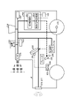
- FIG. 4 is a block diagram showing a schematic configuration of an indoor test device.
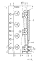
- FIG. 5 is a front view showing a schematic configuration of an indoor test unit, and is a case of relative movement in which surrounding traffic participants move.
- FIG. 6 is a side view showing a schematic configuration of the indoor test unit, and is a case of relative movement in which surrounding traffic participants move.
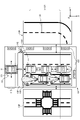
- FIG. 7 is a plan view showing an outline of the vehicle driving test installation, and is a case of relative movement in which surrounding traffic participants move.
- the indoor test unit 4 reproduces the surrounding environment and the driving state of the test target vehicle 8 and acquires the vehicle operation information of the test target vehicle 8.
- the indoor test unit 4 includes a vehicle driving test device 12, an operation information acquisition device 14, and a control device 16.
- the vehicle driving test device 12 includes a test stage 22, an environment reproduction mechanism 26, a traveling condition reproduction mechanism 28, and a building 30.
- the test stage 22 is arranged on one end side in the longitudinal direction of the indoor test unit 4 and in the central portion in the lateral direction, and is configured to be movable in the lateral direction by the moving mechanism 115.
- the test stage 22 is a pallet on which the test target vehicle 8 is installed.
- the test stage 22 changes the posture of the test stage surface 111 on which the test target vehicle 8 is installed.
- the test stage 22 includes four roller belts 112 arranged in the center of the test stage surface 111, each roller belt 112 has a swingable pivot 113, and an actuator 114 capable of expanding and contracting the pivot 113.
- the test stage 22 raises and lowers and tilts the test stage surface 111 by expanding and contracting the actuators 114, respectively, to change the posture.
- the test stage 22 may further have a table mechanism for rotating the test stage surface 111.
- a table mechanism for rotating the test stage surface 111 by providing the roller belt 112, it is possible to perform a test in which the tire of the vehicle 8 to be tested is rotated.
- the test stage 22 may use the test stage surface 111 as a plate-shaped member.
- the test stage 22 changes the posture of the vehicle 8 to be tested by raising and lowering, tilting, and turning the test stage surface 111, and the road surface at the time of turning left / right, cornering, climbing, descending, starting, or braking. Reproduce the attitude toward.
- the environment reproduction mechanism 26 adjusts the environment inside the building 30, and sets the environment around the vehicle 8 to be tested, that is, the environment within the range of detection by the sensor, as the environment of the test conditions.
- the environment reproduction mechanism 26 includes a precipitation facility 102, a snowfall facility 103, a sunshine facility 104, a temperature / humidity pressure control facility 105, a fog generation facility 106, a blower facility 107, a dust generation facility 108, and a hail fall facility 109.
- Precipitation equipment 102 drops a predetermined amount of water as water droplets on the test area to reproduce rain.
- the snowfall equipment 103 manufactures snow, drops the manufactured snow on the test area, and reproduces the snow.
- the sunshine equipment 104 illuminates the test area and reproduces the daytime environment.
- the sunshine equipment 104 may irradiate the vehicle to be tested with a predetermined illuminance light source to reproduce the sun.
- the air temperature / humidity / atmospheric pressure adjusting equipment 105 is an air conditioner having a heating function, a temperature reducing function, a humidifying function, and a dehumidifying function, and the temperature and humidity of the test space are used as test conditions. Further, the air temperature / humidity / atmospheric pressure adjusting equipment 105 is provided with a pump, and the pressure is set as a test condition by pressurizing and depressurizing.
- the fog generator 106 injects mist-like water to reproduce the fog in the test area.
- the blower equipment 107 has a blower capable of controlling the wind direction and speed, and controls the blower so that the wind direction and speed in the test region are set as the upper limit of the test.
- the dust generation equipment 108 generates dust in the test area.
- the hail drop equipment 109 manufactures ice, drops the manufactured ice on the test area, and reproduces the hail.
- the electromagnetic noise generating equipment 110 generates electromagnetic noise around the test area. This makes it possible to create a test environment in which a component that hinders the detection of the sensor is generated.
- the electromagnetic noise reduction equipment 116 reduces the reflected waves of the millimeter wave radar or LiDAR transmitted by the vehicle under test.
- the electromagnetic noise reduction equipment 116 is arranged on a wall surface such as the front of the vehicle 8 to be tested.
- the electromagnetic noise reduction equipment 116 By providing the electromagnetic noise reduction equipment 116, it is possible to suppress the reflection of the millimeter-wave radar and LiDAR transmitted from the vehicle 8 under test at a portion other than the wall surface, for example, a position on an extension of the road under the test conditions, and it is possible to suppress the reflection of the millimeter wave radar and LiDAR emitted from the vehicle 8 to be tested outdoors.
- the environment can be similar to that of the test.
- the environment reproduction mechanism 26 can set the inside of the building 30 as the test condition by controlling each part based on the test condition.
- the traveling condition reproduction mechanism 28 reproduces the traveling state in the region where the sensor of the test target vehicle 8 installed on the test stage 22 executes detection. Specifically, the traveling condition reproduction mechanism 28 moves a relatively moving object under the condition that the test target vehicle 8 is traveling.
- the traveling condition reproduction mechanism 28 includes a road infrastructure 130 and a moving body 140.
- the road infrastructure 130 includes road surfaces 131, 135, 136, and a movable road surface 132.
- the road surface 131 is a road surface that reproduces a road with three lanes.
- the road surface 135 is a road surface having a curve.
- the road surface 135 is partially provided with a stepped road surface 134 whose height changes.
- the road surface 136 is a road surface that reproduces the road at an intersection.
- the road infrastructure 130 has rails, and the road surfaces 131, 135 and 136 are configured to be movable on the rails 137.
- the road infrastructure 130 also includes a mechanism for moving the road surface used for the test to a position facing the test stage 22.
- the road infrastructure 130 may be provided with various road surfaces for testing, such as a road surface that reproduces sandy ground and an unpaved road surface.
- the road infrastructure 130 is provided with a temperature control function 133 inside the road surface 131, and can take a state in which the road surface 131 is frozen or a state in which the road surface is heated.
- the road infrastructure 130 may also have, for example, traffic signals, pedestrian crossings, signs, guardrails and buildings, depending on the purpose of the test.
- the traffic signal, pedestrian crossing, sign, guardrail, and building may be a moving body 140 described later.
- the movable road surface 132 is arranged between the road surface 131 and the test stage surface 111, and changes the direction of the road surface on the entire surface of the test target vehicle 8 in synchronization with the movement of the test stage surface 111. Further, the movable road surface 132 is formed of an endless belt, and the road surface surface is moved according to the traveling conditions of the vehicle 8 to be tested.
- the moving body 140 is various objects that move relative to the vehicle 8 to be tested.
- the moving body 140 includes a peripheral vehicle 141 and a humanoid model 142.
- the moving body 140 is movable with respect to the road infrastructure 130.
- the moving body 140 is placed on the road infrastructure 130 and moves a position on the road surface based on the test conditions.
- the moving body 140 may be moved by remote control, or may be manually or automatically moved based on the test state.
- the building 30 is a building in which the test stage 22, the environment reproduction mechanism 26, and the running condition reproduction mechanism 28 are arranged inside.
- the building 30 uses the surrounding environment of the test target vehicle 8 mounted on the test stage 22 as an indoor environment and is a closed space.
- the space of the road infrastructure is wider than the detection range of the sensor of the vehicle.
- the building 30 preferably has a test area of, for example, 80 m or more in the longitudinal direction and 15 m or more in the lateral direction. It is preferable that the wall surface of the test area of the building 30 is not detected by the sensor unit 121 of the vehicle 8 to be tested.
- the wall surface of the test area of the building 30 may be represented by an image so that the camera 216 does not recognize it as a wall surface.
- the indoor test unit 4 can acquire operation information determined and operated by the test target vehicle 8 under a predetermined environment to be reproduced.
- the operation information acquisition device 14 communicates with the test target vehicle 8 and acquires operation information determined by the vehicle.
- the operation information acquisition device 14 outputs the acquired operation information to the control device 16.
- the operation information acquisition device 14 may be integrated with the indoor test unit 4 or may be integrated with the test target vehicle 8.
- the control device 16 includes a recording unit 310, an input unit 320, a calculation unit 330, and an output unit 340.
- the recording unit 310 stores various data, and the scenario program 311 is recorded.
- the scenario program 311 the traveling conditions of the vehicle, the test conditions reproduced by the environment reproduction mechanism 26, and the transition information of the objects around the traveling vehicle reproduced by the traveling condition reproduction mechanism 28 are stored corresponding to the time axis. To.
- the input unit 320 is a mouse, a keyboard, and a touch panel, and the operator inputs various information.
- the operation unit 321 is an operation device and an emergency stop button of each environment reproduction mechanism, and operates and stops the environment reproduction mechanism.
- the calculation unit 330 calculates adjustment conditions such as the movement amount of the test stage 410, the road infrastructure 430, and the moving body 440 based on the results of the scenario program 311 and the operation information acquisition device 14. Further, the calculation unit 330 outputs the vehicle posture information 18 which is the posture of the vehicle to the test target vehicle 8.
- the vehicle attitude information 18 includes the attitude and acceleration of the vehicle 8 to be tested with respect to the six axes, and also includes information necessary for vehicle control control such as ABS, TCS, and ESC.
- the control device 16 outputs the movement amount and the like calculated by the calculation unit 330 to the output unit 340.
- the output unit 340 outputs various calculation results to the test stage 22, the environment reproduction mechanism 26, the traveling condition reproduction mechanism 28, and the test target vehicle 8.
- the indoor test unit 4 installs the test target vehicle 8 on the test stage 22.
- the indoor test unit 4 acquires the scenario program.
- the scenario program is a time-series condition of the test to be executed for the vehicle 8 to be tested.
- the scenario program is created based on the test conditions.
- the indoor test unit 4 acquires environmental conditions and weather conditions.
- the indoor test unit 4 acquires various test conditions at the time of the object to be reproduced.
- the indoor test unit 4 adjusts the environment reproduction mechanism 26. That is, the temperature, humidity, weather, etc. are the test conditions at the time of the target.
- the indoor test unit 4 adjusts the test stage 22. That is, the posture of the test target vehicle 8 is set as the test condition at the time of the test.
- the indoor test unit 4 adjusts the traveling condition reproduction mechanism 28. That is, the position of the moving body 140 arranged around the test target vehicle 8 is set as the position of the environmental condition at the time of the target.
- the indoor test unit 4 informs the test target vehicle 8 that the conditions and scenario conditions of the test stage 22, the environment reproduction mechanism 26, and the traveling condition reproduction mechanism 28 are satisfied.
- the indoor test unit 4 acquires the operation information of the result recognized and judged by the test target vehicle 8 under the test conditions.
- the indoor test unit 4 calculates the next test state based on the acquired operation information, outputs the conditions and scenario conditions of the test stage 22, the environment reproduction mechanism 26, and the driving condition reproduction mechanism 28, and also outputs the test stage 22 and the scenario conditions.
- the vehicle posture information 18 is output to the test target vehicle 8.
- the indoor test unit 4 determines whether the test is completed. When the indoor test unit 4 determines that the test is not completed, the indoor test unit 4 reproduces the test conditions at the next time point and acquires the operation information of the test target vehicle 8. When the indoor test unit 4 determines that the test is completed, the indoor test unit 4 ends this process.
- FIG. 8 is a flow chart showing an example of the processing operation of the vehicle performance evaluation system 1.
- the management unit 2 determines the test conditions (step S12). In the case of the test of the outdoor test unit 7, the management unit 2 sets conditions other than the conditions that cannot be set such as the weather and the surrounding environment. The management unit 2 sets, for example, the date and time when the test is executed, the course to be run, and the like. When the test of the outdoor test unit 7 is executed by using the test course, the management unit 2 may be a condition for using a reproduction device for the weather, the surrounding environment, etc. prepared for the test course.
- the management unit 2 conducts a vehicle performance test in each test unit and acquires data (step S14).
- the management unit 2 tests the test conditions in each of the indoor test unit 4, the simulation unit 6, and the outdoor test unit 7, and acquires test result data.
- the management unit 2 does not need to be tested by all of the indoor test unit 4, the simulation unit 6, and the outdoor test unit 7, and the test may be performed by the set unit.
- the management unit 2 stores test conditions and test results in the data processing device 52 (step S16). That is, the management unit 2 stores information on the test results of the test target vehicle 8 executed in each test unit. The management unit 2 accumulates the acquired data regarding the test.
- the management unit 2 processes the results of the plurality of test units based on the parameters of the test conditions, and evaluates the test results (step S18). The evaluation process will be described with reference to FIG.
- the management unit 2 outputs the evaluation result (step S20).
- the management unit 2 outputs the evaluation result from the output unit 58.
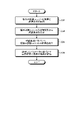
- FIG. 9 is a flowchart showing an example of processing of the data processing apparatus.
- the data processing device 52 will be described as a case where the test is executed in each of the indoor test unit 4, the simulation unit 6, and the outdoor test unit 7.
- the data processing device 52 acquires the results of the plurality of test units and the test conditions (step S32).
- the data processing device 52 calculates the test conditions from the test results of the outdoor test unit (step S34). Specifically, the data processing device 52 determines weather conditions, environmental conditions, and running conditions from the test results of the outdoor test unit 7, and uses the determined results as test conditions.
- the data processing device 52 integrates the results of a plurality of test units based on the test conditions (step S36).
- the data processing device 52 standardizes the test conditions of each of the plurality of test units with the same parameters, and evaluates the test results of different test units with the standardized criteria.
- the data processing device 52 evaluates the performance of the vehicle based on the test results based on the integrated parameters (step S38).
- the data processing device 52 evaluates the performance of the test target vehicle 8 based on the integrated test results based on the standardized standard. This makes it possible to evaluate the results of test units that perform tests in different ways based on one standard.
- FIG. 10 is a flowchart showing an example of processing of the test condition determining device.
- the process shown in FIG. 10 is a process when the indoor test unit executes a test that interpolates the test conditions based on the test conditions of the simulation unit or the outdoor test unit.
- the test condition determination device 50 acquires the test results of the simulation unit or the outdoor test unit (step S42).
- the test condition determination device 50 acquires information on the executed test conditions and test results.
- the test condition determination device 50 converts the results of the plurality of test units based on the parameters of the test conditions (step S44).
- the test condition determination device 50 converts the standardized conditions.
- the test condition determination device 50 calculates the test conditions for extrapolating or interpolating the parameters based on the conversion result (step S46).
- the test condition determination device 50 determines the calculated test conditions for a test to be executed in the indoor test unit (step S48). As a result, the test condition determining device 50 can perform the test under the conditions under which the conditions are changed with respect to the test that has been executed.
- the process is for interpolating the test conditions, but the vehicle performance evaluation system 1 allows the operator to set the test conditions. Further, in the above embodiment, the process is for interpolating the test conditions, but the same test conditions are executed in a plurality of test units in order to evaluate the correlation of the test results of different test units, and the correlation of the test results is obtained. It may be calculated. As a result, the error in each test unit can be interpolated, and the performance of the vehicle can be evaluated with high accuracy by using the test results of a plurality of test units.
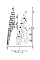
- FIG. 11 is an explanatory diagram for explaining an example of the evaluation result of the vehicle performance evaluation system.
- the vehicle performance evaluation system 1 can perform and evaluate tests under a plurality of different conditions in association with each other by executing and evaluating the tests using a plurality of test units as described above. ..
- FIG. 11 it is possible to summarize the test results for each condition where the weather conditions are fine, rain (rainfall), and fog (visibility), and the performance of the vehicle is evaluated for each condition. Can be done.
- FIG. 11 is a graph showing the relationship between the distance of an object (person) and the detection accuracy under each test condition.
- the vehicle performance evaluation system 1 can show the correlation in the graph shown in FIG. 11 as an example of the evaluation result.
- the vehicle performance evaluation system 1 can perform each measurement in different test units.
- the vehicle performance evaluation system 1 is executed by the indoor test unit 4 using the actual test target vehicle by performing the test using at least one of the simulation unit 6 or the outdoor test unit 7 and the indoor test unit 4.
- the test conditions can be adjusted in higher detail and the vehicle with higher accuracy. Performance can be evaluated.
- the vehicle performance evaluation system 1 can improve the accuracy of the test result of the indoor test unit 4 by comparing the test result of the indoor test unit 4 with the test result of at least one of the simulation unit 6 or the outdoor test unit 7. can. In addition, the performance of the vehicle can be evaluated with high accuracy with a small number of outdoor test units 7.
- the vehicle performance evaluation system 1 can perform a test in which the executed test results are interpolated with high accuracy by determining the test conditions by the test condition determination device 50. As a result, the test can be executed efficiently.
- the data processing device 52 adjusts the parameters of the test conditions at the time of evaluation based on the information of the regulations and ideas to be developed.
- the evaluation results can be output based on the standards corresponding to the regulations and ideas of the development target, and the performance of the test target vehicle can be evaluated more effectively.
- the indoor test unit 4 adjusts the surrounding environment in the building 30, adjusts the position of the moving body around the test target vehicle 8, reproduces the test conditions at each time point, and reproduces the test conditions of the test target vehicle 8 in a state of being reproduced. By acquiring the operation information of, the test state at the next time point is calculated, and by moving each device, the surrounding environment of the test target vehicle 8 can be reproduced.
- the influence of the weather and the environment outside the building 30 can be eliminated, and a highly reproducible test can be performed. This makes it possible to preferably carry out comparative studies. In addition, the test in an extreme environment can be performed with high reproducibility.
- the test conditions are reproduced at each timing corresponding to the predetermined time based on the scenario program, and the operation of the test target vehicle 8 is acquired in a state where the test conditions are reproduced, and the acquisition is completed. , Reproduce at different points in time. This eliminates the need to actually drive the vehicle to be tested, so that the test can be performed in a limited space.
- the predetermined time is exemplified by several tens of msec to 12 msec. The predetermined time may be determined based on the rate of recognition, judgment and operation of the vehicle under test.
- the test target vehicle 8 is installed on the test stage 22, and the traveling condition reproduction mechanism 28 moves the surrounding moving body with respect to the test target vehicle 8, that is, the traveling condition.
- the reproduction mechanism 28 can reduce the size of the test environment by moving the moving object with respect to the test target vehicle 8.
- the object is a moving body 140, which is a peripheral vehicle other than the vehicle to be tested, a model, or an object generally recognized when the vehicle travels on the road.
- the environmental reproduction mechanism 26 can perform tests under various driving conditions by reproducing at least one of rainfall, snowfall, and fog.
- the traveling condition reproduction mechanism 28 may continuously reproduce the traveling conditions and continuously acquire the data. ..
- the indoor test unit 4 can reproduce the condition in which the accident occurred as a scenario program, so that it is possible to determine whether the automatic driving and the driving support are effectively operated in the condition in which the accident occurred. .. Further, the vehicle performance evaluation system 1 can confirm how the automatic driving and driving support operate under the test conditions by supplying the acquired sensor information to the automatic driving and driving support program. .. Further, as described above, the indoor test unit 4 may process the sensor information detected under the test conditions by the automatic driving or driving support program to determine the test conditions at the next time point.
- the indoor test unit 4 preferably has the structure of the above embodiment, but is not limited to the above.
- the indoor test unit 4 may be able to reproduce environmental conditions and weather conditions indoors.
- the test target vehicle 8 is arranged on the test stage 22 (pallet), and the posture of the test target vehicle 8 is changed by the posture of the test stage 22 while the objects arranged around the test stage 22 are relative to each other.
- the relative movement is not limited to the case where the surrounding traffic participants move as in the present embodiment, and the test target vehicle may move as described later.
- traffic participants include other vehicles, motorcycles, bicycles, pedestrians, runways, signs, structures, and the like.
- FIG. 12 is a schematic diagram when the test target vehicle of the indoor test unit moves.
- the indoor test unit 502 is the same as the indoor test unit 4 except for the mechanism of relative movement between the test target vehicle 8 and the objects arranged around it.
- the indoor test unit 502 runs the test target vehicle 8.
- the indoor test unit 502 moves relative to surrounding structures such as a humanoid model 142 and a bicycle 144 by running the test target vehicle 8.
- the indoor test unit 502 reproduces the test conditions by running the vehicle inside the building.
- FIG. 13 is a schematic diagram when the test target vehicle of the indoor test unit moves.
- the indoor test unit 504 is the same as the indoor test unit 4 except for the mechanism of relative movement between the test target vehicle 8 and the objects arranged around it.
- the indoor test unit 504 includes a traction mechanism 550 that pulls the vehicle 8 to be tested. By towing the test target vehicle 8, the traction mechanism 550 moves the test target vehicle 8 relative to surrounding structures such as a humanoid model 142 and a bicycle 144.
- the indoor test unit 502 reproduces the test conditions by towing the vehicle with the towing mechanism 550 inside the building. By using the towing mechanism 550, the test vehicle can be towed under the same conditions, and the reproducibility can be improved.
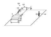
- FIG. 14 is a schematic diagram when the test target vehicle of the indoor test unit moves.
- the indoor test unit 506 shown in FIG. 14 is the same as the indoor test unit 4 except for the mechanism of relative movement between the test target vehicle 8 and the objects arranged around it.
- the indoor test unit 506 includes a mobile trolley 554 for moving the test target vehicle 8.
- the vehicle 8 to be tested is placed on the mobile trolley 554, and the moving trolley 554 is moved in a predetermined direction by a drive mechanism.
- the mobile trolley 554 moves with the test target vehicle 8 mounted on it, so that the test target vehicle 8 moves relative to surrounding structures such as a humanoid model 142 and a bicycle 144.
- the indoor test unit 506 reproduces the test conditions by towing the vehicle with a moving trolley 554 inside the building.
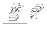
- FIG. 15 is a schematic diagram when the test target vehicle of the indoor test unit moves.
- the indoor test unit 510 shown in FIG. 15 is the same as the indoor test unit 4 except for the mechanism of relative movement between the test target vehicle 8 and the objects arranged around it.
- the indoor test unit 510 drives the test target vehicle 8.
- the indoor test unit 510 also moves surrounding structures, a humanoid model 142, a bicycle 144, and a vehicle 556 by their respective driving methods.
- the indoor test unit 510 relatively moves the test target vehicle 8 and its surroundings by moving the test target vehicle 8, the humanoid model 142, the bicycle 144, and the vehicle 556, respectively.
- FIG. 16 is a schematic diagram when the test target vehicle of the indoor test unit moves.
- the indoor test unit 512 shown in FIG. 16 is the same as the indoor test unit 4 except for the mechanism of relative movement between the test target vehicle 8 and the objects arranged around it.
- the indoor test unit 512 drives the test target vehicle 8.
- the indoor test unit 512 also moves the surrounding structures, the humanoid model 142, the bicycle 144, and the vehicle 556 by the respective traction mechanisms 560, 562, and 564.
- the towing mechanism 560 pulls the vehicle 556 to move the vehicle 556 relative to the vehicle 8 to be tested.
- the traction mechanism 562 pulls the humanoid model 142 to move the humanoid model 142 relative to the vehicle 8 to be tested.
- the towing mechanism 562 pulls the bicycle 144 to move the bicycle 144 relative to the vehicle 8 to be tested.
- the indoor test unit 512 reproduces the test conditions by running the vehicle inside the building and moving the surrounding structures, the humanoid model 142, the bicycle 144, and the vehicle 556 by the respective traction mechanisms 560, 562, 564, respectively. ..
- the test vehicle can be towed under the same conditions, and the reproducibility can be improved.
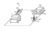
- FIG. 17 is a schematic diagram when the test target vehicle of the indoor test unit moves.
- the indoor test unit 514 shown in FIG. 17 is the same as the indoor test unit 4 except for the mechanism of relative movement between the test target vehicle 8 and the objects arranged around it.
- the indoor test unit 514 drives the test target vehicle 8.
- the indoor test unit 514 also moves the surrounding structures, the humanoid model 142, the bicycle 144, and the vehicle 556 by the mobile trolleys 570, 572, and 574, respectively.
- the mobile trolley 570 moves the vehicle 556 relative to the test target vehicle 8 by moving with the vehicle 556 mounted.
- the mobile trolley 572 moves the humanoid model 142 relative to the test target vehicle 8 by moving the humanoid model 142 in a mounted state.
- the mobile trolley 574 moves the bicycle 144 relative to the test target vehicle 8 by moving the bicycle 144 in a mounted state.
- the indoor test unit 514 reproduces the test conditions by running the vehicle inside the building and moving the surrounding structures, the humanoid model 142, the bicycle 144, and the vehicle 556 by the respective mobile trolleys 570, 572, and 574. ..
- Vehicle performance evaluation system 2 Management unit 3 1st test unit 4 Indoor test unit 5 2nd test unit 6 Simulation unit 7 Outdoor test unit 8 Test target vehicle 12 Vehicle operation test device 14 Operation information acquisition device 16 Control device 18 Vehicle attitude information 22 Test stage 26 Environmental reproduction mechanism 28 Driving condition reproduction mechanism 30 Building 50 Test condition determination device 52 Data processing equipment 54 Database 56 Input unit 58 Output unit 102 Precipitation equipment 103 Snowfall equipment 104 Sunlight equipment 105 Temperature / humidity pressure adjustment equipment 106 Fog generation equipment 107 Blower equipment 108 Dust generation equipment 109 Hallowing equipment 110 Electromagnetic noise generation equipment 111 Test stage surface 112 Roller belt 113 Pivot 114 Actuator 115 Movement mechanism 116 Electromagnetic noise reduction equipment 121 Sensor unit 122 Sensor information output unit 123 Operation information output unit 130 Road infrastructure 131, 135, 136 Road surface 132 Movable road surface 133 Temperature control function 134 Stepped road surface 137 Rail 140 Moving body 141 Peripheral vehicle 142 Humanoid model 144 Bicycle 202 Steering device 204 Opera
Landscapes
- Engineering & Computer Science (AREA)
- Physics & Mathematics (AREA)
- Radar, Positioning & Navigation (AREA)
- Remote Sensing (AREA)
- General Physics & Mathematics (AREA)
- Computer Networks & Wireless Communication (AREA)
- Electromagnetism (AREA)
- Traffic Control Systems (AREA)
Abstract
車両の性能を試験する第1試験ユニットと、第1試験ユニットとは異なる方式で車両の性能を試験する少なくとも1つの第2試験ユニットと、第1試験ユニットの試験結果及び第2試験ユニットの試験結果を、気象条件を含む試験条件に基づいて合わせ込み処理を行い、評価を出力するデータ処理装置と、を含み、第1試験ユニットは、試験対象車両の周囲の環境を再現する環境再現機構と、試験対象車両に対して相対移動し、車両の走行状態を再現する走行条件再現機構と、環境再現機構、走行条件再現機構を覆い、試験ステージの周囲を屋内空間とする建屋と、を備える。
Description
本開示は、車両性能評価システム、車両性能評価方法及び車両性能評価プログラムに関する。
車両の試験装置としては、安全性を確認する衝突試験装置や、走行性能を確認するテストコース等がある。特許文献1では、実環境に存在する様々な路面状態における周辺車両の挙動を模擬して、安全運転支援用アプリケーションの動作試験を実施する試験システムおよび試験方法の発明が記載されている。
近年、自動運転等の運転を支援する機能を備える車両が開発されている。運転支援機能を備える車両は、走行状態を検出して、その結果に基づいて車両の挙動の制御、運転支援の情報の出力を行う。走行状態とは、自車両の状態と周囲の交通参加者(他車両、バイク、自転車、歩行者、走路、標識、構造物等)を含む。そのため、走行状態の検出が適切に行われているか、また、検出した走行状態に適した制御を行っているかを評価する必要がある。
特許文献1に記載のシミュレーションでは、シミュレーションで解析することができるが、車両の設計には、実際の試験も必要となる。そのため、シミュレーションの結果を有効に活用するために工夫が必要である。
上記課題を解決するために、本開示は、車両の性能をより詳細に評価できる車両性能評価システム、車両性能評価方法及び車両性能評価プログラムを提供する。
本開示の車両性能評価システムは、車両の性能を試験する第1試験ユニットと、前記第1試験ユニットとは異なる方式で前記車両の性能を試験する少なくとも1つの第2試験ユニットと、前記第1試験ユニットの試験結果及び前記第2試験ユニットの試験結果を、管理する管理ユニットにて構成する。管理ユニットは、気象条件を含む試験条件に基づいて合わせ込み処理を行う試験条件決定装置と、評価を出力するデータ処理装置と、データベースを含み、前記第1試験ユニットは、試験対象車両の周囲の環境を再現する環境再現機構と、前記試験対象車両に対して相対移動し、前記車両の走行状態を再現する走行条件再現機構と、前記環境再現機構、前記走行条件再現機構を覆い、前記車両の周囲を屋内空間とする建屋と、を備える。相対移動は、周囲の交通参加者が移動する場合と試験対象車両が移動する場合がある。
本開示の車両性能評価方法は、第1試験ユニットで実行した試験の試験条件と、試験結果の車両の性能とを取得するステップと、前記第1試験ユニットとは異なる方式で前記車両の性能を試験する少なくとも1つの第2試験ユニットで実行した試験の試験条件と試験結果の車両の性能とを取得するステップと、前記第1試験ユニットの試験結果及び前記第2試験ユニットの試験結果を、気象条件を含む試験条件に基づいて合わせ込み処理を行い、評価を出力するステップと、を含み、前記第1試験ユニットは、試験対象車両の周囲の環境を再現する環境再現機構と、前記試験対象車両に対して相対移動し、前記車両の走行状態を再現する走行条件再現機構と、前記走行条件再現機構、前記環境再現機構を覆い、前記試験ステージの周囲を屋内空間とする建屋と、を備える。
本開示の車両性能評価プログラムは、試験対象車両の周囲の環境を再現する環境再現機構と、前記試験対象車両に対して相対移動し、前記車両の走行状態を再現する走行条件再現機構と、前記走行条件再現機構、前記環境再現機構を覆い、前記試験ステージの周囲を屋内空間とする建屋と、を備える第1試験ユニットで実行した試験の試験条件と、試験結果の車両の性能とを取得するステップと、前記第1試験ユニットとは異なる方式で前記車両の性能を試験する少なくとも1つの第2試験ユニットで実行した試験の試験条件と試験結果の車両の性能とを取得するステップと、前記第1試験ユニットの試験結果及び前記第2試験ユニットの試験結果を、気象条件を含む試験条件に基づいて合わせ込み処理を行い、評価を出力するステップと、を含む。
本開示によれば、車両の性能をより詳細に評価できる。
以下、本開示の実施形態について図を用いて詳細に説明する。なお、この実施形態で説明するのは本発明の一実施例であり、これにより本発明が限定されるものではない。
図1は、実施形態に係る車両性能評価システム1の概略構成を示すブロック図である。車両性能評価システム1は、管理ユニット2と、第1試験ユニット3と、第2試験ユニット5と、を含む。第1試験ユニット3は、屋内試験ユニット4を含む。第2試験ユニット5は、シミュレーションユニット6と、屋外試験ユニット7と、を含む。本実施形態の第1試験ユニット3は、1つの屋内試験ユニット4であるが、複数の屋内試験ユニット4を含んでもよい。本実施形態の第2試験ユニット5は、シミュレーションユニット6と、屋外試験ユニット7とを備えているが、いずれか一方のみを備えていてもよいし、シミュレーションユニット6と、屋外試験ユニット7と、をそれぞれ複数備えていてもよい。車両性能評価システム1は、試験対象車両8の試験を行い、試験対象車両8の性能を評価する。試験対象車両8は、1台でも同じ機能を備える複数台でもよい。また、シミュレーションユニット6で試験する試験対象車両8は、試験対象車両8の制御機能を備えていればよく、車体、タイヤ、原動機、センサ等を備えている必要はない。試験対象車両8の性能とは、走行時の性能である。車両性能評価システム1は、自動運転を含む運転支援機能の性能を評価する。運転支援機能としては、搭乗者が操作を行わず車両を走行させる自動運転機能、周囲の状況を検出して、警告や案内を行い、搭乗者の走行を支援する機能等が含まれる。自動運転機能には、各種レベルの自動運転に対応する機能が含まれる。
管理ユニット2は、試験を行う複数のユニットで実行する試験を管理する。管理ユニット2は、試験を行う各ユニットの試験結果の情報を取得し、蓄積する。管理ユニット2は、試験結果の解析を行い、解析結果を出力する。また、管理ユニット2は、各ユニットで実行する試験の条件、つまり試験条件を決定する。管理ユニット2は、試験条件決定装置50と、データ処理装置52と、データベース54と、入力部56と、出力部58と、を含む。なお、管理ユニット2は、1つのパーソナルコンピュータでもよいが、複数の演算装置を有線、無線のネットワークで接続した構成としてもよい。管理ユニット2は、入力部56、出力部58を複数備えていてもよい。例えば、試験条件決定装置50、データ処理装置52、データベース54のそれぞれに対して、入力部56、出力部58を設けてもよい。入力部56は、ユーザの入力を受け付ける装置であり、例えばマウス、キーボード、又はタッチパネル等である。出力部58は、試験条件決定装置50、データ処理装置52の演算結果、データベースのデータやユーザからの入力内容などを表示する装置である。出力部58は、例えば、ディスプレイやタッチパネルである。
試験条件決定装置50は、屋内試験ユニット4、シミュレーションユニット6、屋外試験ユニット7で、実行する試験対象車両8の試験の条件を決定する。試験条件決定装置50は、演算装置、すなわちCPU(Central Processing Unit)と、記憶装置、すなわち演算内容やプログラムの情報などを記憶するメモリとを含む。メモリは、例えば、RAM(Random Access Memory)と、ROM(Read Only Memory)と、HDD(Hard Disk Drive)などの外部記憶装置とのうち、少なくとも1つ含む。試験条件決定装置50は、評価取得部302と、ユニット情報取得部304と、試験条件算出部306と、を含む。
評価取得部302は、屋内試験ユニット4、シミュレーションユニット6、屋外試験ユニット7で実行した試験対象車両8の試験条件と試験結果を取得する。試験条件は、試験対象車両8の車両情報、走行条件、環境条件、天候条件が含まれる。走行条件は、試験対象車両8の走行速度、操舵角、駆動源の出力、制動動作等である。環境条件は、気温、明るさ、太陽の位置、路面状況、試験対象車両8の走行時の周囲の状況等である。路面状況とは、走行する路面が乾いているか、濡れているか、凍結しているか、雪が積もっているか、舗装されているか、等である。試験対象車両8の走行時の周囲の状況とは、歩行者、自転車に乗っている人、対向車等の有無、位置、移動方向、移動速度や、道路の標識の位置、車線数等である。天候条件は、晴れ、曇り、雨、雪、雹、霧、砂嵐等の天候、風向、風速等である。雨等の場合は、降雨量等も条件に含まれる。試験の結果には、試験中に試験対象車両8が取得した情報、実行した制御等が含まれる。
ユニット情報取得部304は、屋内試験ユニット4、シミュレーションユニット6、屋外試験ユニット7の情報を取得する。具体的には、ユニット情報取得部304は、屋内試験ユニット4、シミュレーションユニット6、屋外試験ユニット7のそれぞれで実行可能な試験の条件や、各試験ユニットで試験結果や環境条件を検出する機器、性能の情報を取得する。
試験条件算出部306は、評価取得部302で取得した実行済みの試験の情報、ユニット情報取得部304で取得した各ユニットの情報に基づいて、実行する試験の条件を算出する。
データ処理装置52は、各ユニットで実行した試験の結果と、当該試験の条件に基づいて、試験結果を処理して、試験結果を評価する。データ処理装置52は、演算装置、すなわちCPU(Central Processing Unit)と、記憶装置、すなわち演算内容やプログラムの情報などを記憶するメモリとを含む。メモリは、例えば、RAM(Random Access Memory)と、ROM(Read Only Memory)と、HDD(Hard Disk Drive)などの外部記憶装置とのうち、少なくとも1つ含む。データ処理装置52は、試験結果取得部312と、パラメータ変換部314と、試験結果統合部316と、評価部318と、を含む。
試験結果取得部312は、屋内試験ユニット4、シミュレーションユニット6、屋外試験ユニット7で実行した試験対象車両8の試験条件と試験結果を取得する。試験条件は、試験対象車両8の車両情報、走行条件、環境条件、天候条件が含まれる。
パラメータ変換部314は、各ユニットで実行した試験の試験条件を、同一のパラメータで評価可能な状態に変換する。ここで、パタメータは、試験対象車両8の試験時に検出または設定できる条件であり、天候条件、環境条件、走行条件から選択した条件である。例えば、環境条件を一定としつつ、降雨量をパラメータとしたり、走行条件を一定としつつ、路面の状態(濡れているか乾いているか、濡れている程度、路面摩擦係数)をパラメータとしたりすることができる。パラメータ変換部314は、試験条件に基づいてパラメータを整理することで、異なるユニットで実行した試験を同じパラメータで評価できる状態とする。
試験結果統合部316は、パラメータ変換部314で変換した結果に基づいて、異なるユニットで実行した試験の結果を統合する。これにより、試験対象車両8に対して実行する複数のユニットでの試験結果を比較可能にする。
評価部318は、試験結果統合部316で統合した試験結果に基づいて、試験対象車両8の性能を評価する。評価部318は、評価の結果として、試験結果統合部316で統合したパラメータに基づいたグラフを作成して出力してもよい。
データベース54は、管理ユニット2の処理を実行するプログラムや、車両性能評価システム1で取得した各種試験に関するデータを記憶し、管理する。データベース54は、演算装置、すなわちCPU(Central Processing Unit)と、記憶装置、すなわち演算内容やプログラムの情報などを記憶するメモリとを含む。メモリは、例えば、RAM(Random Access Memory)と、ROM(Read Only Memory)と、HDD(Hard Disk Drive)などの外部記憶装置とのうち、少なくとも1つ含む。データベース54は、演算装置を備えず、記憶装置のみを備え、試験条件決定装置50、データ処理装置52で、データの処理(書き込み、読み出し)を行ってもよい。また、本実施形態では、データベース54を備える構成としたが、管理ユニット2は、試験条件決定装置50、データ処理装置52の記憶装置に各種データを記憶させてもよい。データベース54は、性能試験プログラム322と、試験条件データベース324と、試験結果データベース326と、評価データベース328と、を含む。
性能試験プログラム322は、車両性能評価システム1、管理ユニット2で実行する各種処理を実行するためのプログラムである。性能試験プログラム322は、例えば、試験条件決定装置50、データ処理装置52の処理を実行するプログラムである。車両性能評価システム1は、屋内試験ユニット4、シミュレーションユニット6、屋外試験ユニット7で試験を実行するためのプログラムを性能試験プログラム322に含めても、別のプログラムとしてもよい。性能試験プログラム322は、1つのプログラムである必要はなく、複数のプログラムの組み合わせでよい。
試験条件データベース324は、屋内試験ユニット4、シミュレーションユニット6、屋外試験ユニット7で実行する試験の条件のデータである。試験条件データベース324は、屋内試験ユニット4、シミュレーションユニット6で実行可能な試験条件の範囲の情報や、屋外試験ユニット7で取得した結果に基づいて試験条件を算出するための情報を含む。試験条件データベース324は、屋内試験ユニット4、シミュレーションユニット6、屋外試験ユニット7で実行した各試験の試験条件の情報を試験結果に対応つけたデータを含む。
試験結果データベース326は、屋内試験ユニット4、シミュレーションユニット6、屋外試験ユニット7で実行し、取得した試験結果のデータである。試験結果は、実行した試験で試験対象車両8から取得したデータ、試験条件等を確認するために取得したデータが含まれる。試験対象車両8から取得したデータには、試験対象車両8に搭載したセンサの検出や、試験対象車両8の制御部で算出した処理結果が含まれる。
評価データベース328は、評価部318で評価を実行するために使用する各種処理条件、閾値、また、評価結果を出力するためのグラフ、表等のテンプレートのデータである。
屋内試験ユニット4は、屋内で試験対象車両8の走行状態を再現し、試験対象車両8の試験を行う。屋内試験ユニット4は、屋内で走行条件、環境条件、天候条件を再現できる。屋内試験ユニット4については、後述する。
シミュレーションユニット6は、試験対象車両8の走行試験をシミュレーションで実行する。シミュレーションユニット6は、演算装置、すなわちCPU(Central Processing Unit)と、記憶装置、すなわち演算内容やプログラムの情報などを記憶するメモリとを含む。メモリは、例えば、RAM(Random Access Memory)と、ROM(Read Only Memory)と、HDD(Hard Disk Drive)などの外部記憶装置とのうち、少なくとも1つ含む。シミュレーションユニット6は、管理ユニット2の一部としてもよい。シミュレーションユニット6は、条件取得部402と、解析実行部404と、出力部406と、を含む。
条件取得部402は、50または入力部56に入力された試験条件を取得する。試験条件は、試験対象車両8の情報、走行条件、環境条件、天候条件等である。解析実行部404は、条件取得部402で取得した試験条件に基づいて試験対象車両8の試験をシミュレーションで実行する。解析実行部404が実行するシミュレーションは種々のシミュレーションとすることができる。解析実行部404は、試験対象車両8の制御機能を実行する処理部を有し、試験条件に基づいて試験対象車両8が走行した場合に試験対象車両8の各種センサが取得する情報を作成して、処理部に入力する。解析実行部404は、処理部から出力される制御情報を試験結果として取得する。出力部406は、解析実行部404で取得した試験結果を管理ユニット2に出力する。
屋外試験ユニット7は、試験対象車両8の走行試験を屋外で実行する。屋外試験ユニット7は、屋外で試験対象車両8を走行させ、試験対象車両8から取得した情報、試験対象車両8の周囲の情報を処理して、試験条件、試験結果を算出する。屋外試験ユニット7は、試験対象車両8をテストコースで走行させる試験や、公道で走行させる試験の両方を実行できる。テストコースは、閉鎖された敷地に設けられた施設であり、天候条件、環境条件を再現するための各種施設を備えることができる。公道は、試験対象車両8以外の試験に関係のない車両、人の往来が生じる可能性がある場所である。屋外試験ユニット7は、位置検出部452と、環境情報取得部454と、車両情報取得部456と、を含む。
位置検出部452は、試験時の試験対象車両8の走行位置を検出する。位置検出部452は、例えば、試験対象車両8に搭載され、GSNN(Global Navigation Satellite System:全球測位衛星システム)を用いて、地球上での位置を検出する。位置検出部452は、GSNNを用いた方法に限定されず、公衆無線通信網の基地局との通信や、周囲の画像から位置を検出してもよい。
環境情報取得部454は、試験時の試験対象車両8の周囲の情報を取得する。環境情報取得部454は、試験対象車両8の周囲を撮影する撮影部や、明るさ、温度、湿度を検出するセンサ等を含む。環境情報取得部454は、撮影部で取得した情報に基づいて、対向車の情報、前後の車両の状況、周囲を通行する人、自転車等の情報を取得する。環境情報取得部454は、試験対象車両8の試験時の天候の情報等を天候情報が記録されるデータサーバから取得する機能も備える。環境情報取得部454は、位置検出部452で検出した位置情報と、位置情報と環境情報(路面、周囲の情報)等が対応付けられた地図情報に基づいて、試験時に試験対象車両8が走行している位置の環境条件に対応する情報を取得する。
車両情報取得部456は、試験時に試験対象車両8で取得した制御に必要な情報及び試験対象車両8の制御部から各部に出力された制御情報を取得する。試験対象車両8で取得した制御に必要な情報は、各種センサで取得した情報、例えば温度、湿度、周囲の障害物、対向車、前後の車両の情報である。試験対象車両8の制御部から各部に出力された制御情報は、駆動部への速度制御情報、操舵制御情報、運転者への通知情報、ライト、クラクション等の外部へ出力した情報等である。
次に、図2及び図3を用いて、試験対象車両8の一例を説明する。図2は、試験対象車両の機能構成を示すブロック部である。図3は、試験対象車両のセンサ機能を説明するための説明図である。本実施形態の試験対象車両8は、自動運転機能を含む運転支援機能を備えている。本実施形態の車両性能評価システム1は、試験対象車両8の運転支援機能の性能を試験し、評価する。また、試験対象車両8は、図2に示すように、操舵装置202、操作ペダル204を備えている。試験対象車両8は、移動体として必要な各種機構、具体的には、車体、タイヤ、駆動源、操作部等を備えている。操舵装置202は、運転者がタイヤの旋回操作を入力する機器である。操作ペダル204は、アクセルペダル、ブレーキペダルを含み、運転者が加速、減速等、駆動力の動作を入力する機器である。
試験対象車両8は、周辺の環境を検出するセンサを備えており、センサの検出結果に基づいて、自動運転または運転支援を行う。試験対象車両8は、センサユニット121と操作情報出力部123と、を含む。試験対象車両8は、上記構成以外にも走行に必要な各種機能を備えている。なお、試験対象車両8は、試験体として、車体と必要なセンサのみを備える構造としてもよい。
センサユニット121は、自車の周囲の情報を取得するセンサ及び試験対象車両8に入力される操作を取得するセンサである。センサユニット121は、自社の周囲の情報を取得するセンサとして、カメラ、ミリ波レーダ、赤外線センサ、LiDAR(Light Detection and Ranging、Laser Imaging Detection and Ranging)等の周囲の物体、状況を検出する各種センサを用いることができる。図2及び図3に示す試験対象車両8は、車両前方に、ミリ波レーダ214、カメラ216、LiDAR217、車両側面にミリ波レーダ215、車両側面と後方にカメラ216を備えている。ミリ波レーダ214は、遠方の物体を検出できるセンサ、例えば、76-78GHzのミリ波レーダであり、測定範囲224の情報を取得する。ミリ波レーダ215は、ミリ波レーダ214よりも狭い範囲の物体を検出するセンサ、例えば、24GHzのミリ波レーダであり、測定範囲225の情報を取得する。カメラ216は、撮影範囲226の画像を取得する。LiDAR217は、車両前方の測定範囲227の情報を取得する。車両の上部のLiDAR230は、車両上部、及び前後左右の情報を取得する。
センサユニット121は、試験対象車両8に入力される操作を取得するセンサとして、車速センサ232、加速度センサ234、操作検出部236、238、位置センサ240を含む。車速センサ232は、試験対象車両8の走行速度を検出する。加速度センサ234は、ジャイロセンサ等であり、試験対象車両8の各方向の加速度を検出して、各方向の加速度と試験対象車両8の姿勢を検出する。操作検出部236は、試験対象車両8に入力される操舵操作を検出する。操作検出部238は、試験対象車両8に入力されるアクセル操作、ブレーキ操作等の駆動源に対する操作を検出する。位置センサ240は、GSNNを用いて試験対象車両8の位置を検出する。
制御装置206は、試験対象車両8の運転支援機能の制御を実行する。制御装置206は、環境認識部207と、制御信号生成部208と、を含む。環境認識部207は、センサユニット121で取得した情報に基づいて、試験対象車両8の周囲の状況を認識する。制御信号生成部208は、環境認識部207で認識した周囲の状況に基づいて、試験対象車両8の運転を支援する制御を決定し、決定した制御を実行する制御信号を生成する。制御信号生成部208は、生成した制御信号を操舵装置202、操作ペダル204に入力する。本実施形態の制御装置206は、運転支援機能として、操舵、加減速を制御する。例えば、制御装置206は、運転支援機能として、自動運転や、衝突回避、危機回避を行う。
試験対象車両8は、屋内試験ユニット4の一部でもあるセンサ情報出力部122及び操作情報出力部123と、屋外試験ユニット7の一部である位置検出部452、環境情報取得部454、車両情報取得部456を含む。センサ情報出力部122は、センサユニット121で取得した情報を出力する。操作情報出力部123は、試験対象車両8が判断した操作情報を出力する。ここで、操作情報には、ハンドル、アクセル、ブレーキ、シフトチェンジ等の操作結果の情報が含まれる。位置検出部452、環境情報取得部454、車両情報取得部456は、試験対象車両8の各センサから検出結果を取得する。
試験対象車両8は、屋内試験ユニット4のみに対応する車両とする場合、屋外試験ユニット7の一部である位置検出部452、環境情報取得部454、車両情報取得部456を備えていなくてもよい。また、試験対象車両8は、屋内試験ユニット4のみに対応する車両とする場合、位置情報は、通信等で仮定の位置情報を入力してもよい。また、試験対象車両8は、シミュレーションに対応する場合、制御装置206のみの機能を備えていればよい。
次に、図4から図7を用いて、屋内試験ユニットについて説明する。図4は、屋内試験装置の概略構成を示すブロック図である。図5は、屋内試験ユニットの概略構成を示す正面図であり、周囲の交通参加者が移動する相対移動の場合である。図6は、屋内試験ユニットの概略構成を示す側面図であり、周囲の交通参加者が移動する相対移動の場合である。図7は、車両運転試験置概略を示す平面図であり、周囲の交通参加者が移動する相対移動の場合である。図4に示すように、屋内試験ユニット4は、試験対象車両8の周囲環境と運転状態を再現して、試験対象車両8の車両操作情報を取得する。屋内試験ユニット4は、車両運転試験装置12と、操作情報取得装置14と、制御装置16と、を含む。車両運転試験装置12は、試験ステージ22と、環境再現機構26と、走行条件再現機構28と、建屋30と、を含む。
試験ステージ22は、屋内試験ユニット4の長手方向の一端側で、かつ短手方向における中央部に配置され、移動機構115により短手方向に移動可能に構成される。試験ステージ22は、試験対象車両8が設置されるパレットである。試験ステージ22は、試験対象車両8が設置される試験ステージ面111の姿勢を変化させる。試験ステージ22は、試験ステージ面111中央に配置された4つのローラーベルト112と、それぞれのローラーベルト112は旋回可能なピボット113と、ピボット113を伸縮可能なアクチュエータ114とを備える。試験ステージ22は、アクチュエータ114をそれぞれ伸縮させることにより、試験ステージ面111を昇降および傾斜させ、姿勢を変化させる。試験ステージ22は、さらに試験ステージ面111を回転させるテーブル機構を有してもよい。なお、本実施形態では、ローラーベルト112を設けることで、試験対象車両8のタイヤを回転させる試験が可能となる。試験ステージ22は、試験対象車両8を走行させない場合は、試験ステージ面111を板状の部材としてもよい。
試験ステージ22は、試験ステージ面111を昇降、傾斜および旋回させることで、試験対象車両8の姿勢を変化させ、右左折時、コーナーリング時、登坂時、降坂時、発進時あるいは制動時の路面に対する姿勢を再現する。
環境再現機構26は、建屋30内の環境を調整し、試験対象車両8の周囲、つまり、センサで検出を行う範囲の環境を試験条件の環境とする。環境再現機構26は、降水設備102と、降雪設備103と、日照設備104と、気温湿度気圧調整設備105と、霧発生設備106と、送風設備107と、発塵設備108と、降雹設備109と、電磁ノイズ発生設備110と、電磁ノイズ軽減設備116と、を含む。降水設備102は、所定量の水を水滴として試験領域に降らせ、雨を再現する。降雪設備103は、雪を製造し、製造した雪を試験領域に降らせ、雪を再現する。日照設備104は、試験領域を照明し、日中の環境を再現する。日照設備104は、所定照度光源を試験対象車両に向けて照射し、太陽を再現するようにしてもよい。気温湿度気圧調整設備105は、加温機能、減温機能、加湿機能、除湿機能を備えるエアコンディショナーであり、試験空間の温度、湿度を試験条件とする。さらに、気温湿度気圧調整設備105は、ポンプを備え、加圧減圧することで、圧力を試験条件とする。霧発生設備106は、ミスト状の水を噴射し、試験領域に霧を再現する。送風設備107は、風向風速を制御できる送風機を有し、送風機を制御して、試験領域の風向、風速を試験上限とする。発塵設備108は、試験領域に塵を発生させる。降雹設備109は、氷を製造し、製造した氷を試験領域に降らせ、雹を再現する。電磁ノイズ発生設備110は、試験領域の周囲に電磁ノイズを発生させる。これにより、センサの検出を阻害する成分が発生した試験環境とすることができる。電磁ノイズ軽減設備116は、試験対象車両が発信するミリ波レーダもしくは、LiDARの反射波を軽減する。電磁ノイズ軽減設備116は、試験対象車両8の正面等の壁面に配置される。電磁ノイズ軽減設備116を設けることで、試験条件において、壁面ではない部分、例えば道路の延長線上の位置で、試験対象車両8から発信するミリ波レーダ、LiDARを反射することを抑制でき、屋外の試験と同様の環境とすることができる。環境再現機構26は、試験条件に基づいて、各部を制御することで、建屋30の内部を試験条件とすることができる。
走行条件再現機構28は、試験ステージ22に設置された試験対象車両8のセンサが検出を実行する領域の走行状態を再現する。具体的には、走行条件再現機構28は、試験対象車両8が走行している条件とした場合に相対的に移動する対象物を移動させる。走行条件再現機構28は、道路インフラ130と、移動体140と、を含む。
道路インフラ130は、路面131、135、136、可動路面132を備える。本実施形態では路面131は、3車線の道路を再現した路面である。路面135は、カーブを備える路面である。路面135は、一部に高さが変化する段差路面134が設けられる。路面136は、交差点の道路を再現した路面である。道路インフラ130はレールを有しており、路面131、135および136はレール137上を移動可能に構成されている。道路インフラ130は、試験ステージ22と対面する位置に試験に用いる路面を移動させる機構も備える。また道路インフラ130は、砂地を再現した路面や、未舗装の路面等、試験を行う各種路面を設けてもよい。道路インフラ130は、路面131の内部に温調機能133を備えており、路面131が凍結した状態や路面が熱された状態を取ることができる。また、道路インフラ130は、試験の目的に応じて例えば交通信号、横断歩道、標識、ガードレールおよび建物を有してもよい。なお、交通信号、横断歩道、標識、ガードレールおよび建物は、後述する移動体140としてもよい。可動路面132は、路面131と試験ステージ面111との間に配置され、試験ステージ面111の移動に同期して、試験対象車両8の全面の路面の向きを変化させる。また、可動路面132は、エンドレスベルトで形成され、試験対象車両8の走行条件に合わせて、路面表面を移動させる。
移動体140は、試験対象車両8に対して相対的に移動する各種物体である。移動体140は、周辺車両141、人型模型142を含む。移動体140は、道路インフラ130に対して移動可能である。移動体140は、道路インフラ130の上に配置され、試験条件に基づいて、路面上の位置を移動する。移動体140は、遠隔操作により移動しても、試験状態に基づいて、手動、自動で移動させてもよい。
建屋30は、試験ステージ22と、環境再現機構26と、走行条件再現機構28が内部に配置された建造物である。建屋30は、試験ステージ22に載置される試験対象車両8の周囲環境を室内の環境とし、閉鎖された空間とする。建屋30は、道路インフラの空間が、車両のセンサの検出範囲よりも広いことが好ましい。建屋30は、試験領域が例えば長手方向が80m以上、短手方向が15m以上となることが好ましい。建屋30の試験領域の壁面を試験対象車両8のセンサユニット121が壁面として、検知しない構造とすることが好ましい。具体的には、試験対象車両8のセンサの検波用の波長を吸収する構造とすることが好ましい。また、建屋30の試験領域の壁面は、カメラ216が壁面と認識しないように、画像を表記させるようにしてもよい。
屋内試験ユニット4は、再現される所定の環境下において、試験対象車両8が判断し操作した操作情報を取得することができる。
操作情報取得装置14は、試験対象車両8と通信を行い、車両が判断した操作の情報を取得する。操作情報取得装置14は、取得した操作の情報を制御装置16に出力する。操作情報取得装置14は、屋内試験ユニット4と別体としても一体としてもよいし、試験対象車両8と一体としても別体としてもよい。
制御装置16は、記録部310、入力部320、演算部330、出力部340を備える。記録部310は、各種データを記憶しており、シナリオプログラム311が記録されている。シナリオプログラム311は、車両の走行条件、環境再現機構26で再現する試験条件、走行条件再現機構28で再現する走行している車両の周囲の物体の遷移情報が、時間軸に対応して記憶される。
入力部320は、マウス、キーボート、タッチパネルであり、オペレータが各種情報を入力する。操作部321は各環境再現機構の操作機器及び非常停止ボタンであり、環境再現機構の動作及び停止操作を行う。演算部330は、シナリオプログラム311や操作情報取得装置14の結果に基づいて、試験ステージ410、道路インフラ430および移動体440の移動量等の調整条件を算出する。また、演算部330は、試験対象車両8へ車両の姿勢である車両姿勢情報18を出力する。ここで、車両姿勢情報18には、試験対象車両8の6軸についての姿勢及び加速度が含まれるほか、例えばABS、TCS、ESCといった車両制御コントロールに必要な情報が含まれる。制御装置16は、演算部330で算出した移動量等を出力部340へ出力する。出力部340は、試験ステージ22、環境再現機構26、走行条件再現機構28及び試験対象車両8に各種演算結果を出力する。
次に、屋内試験ユニット4を用いた、試験対象車両8の運転性能の試験方法について説明する。屋内試験ユニット4は、試験対象車両8を試験ステージ22に設置する。屋内試験ユニット4は、シナリオプログラムを取得する。シナリオプログラムは、試験対象車両8に対して実行する試験の時系列の条件である。シナリオプログラムは、試験条件に基づいて作成される。
屋内試験ユニット4は、環境条件と天候条件を取得する。屋内試験ユニット4は、再現する対象の時点での各種試験条件を取得する。屋内試験ユニット4は、環境再現機構26を調整する。つまり、温度湿度天候等を対象の時点の試験条件とする。屋内試験ユニット4は、試験ステージ22を調整する。つまり、試験対象車両8の姿勢を対象の時点の試験条件とする。屋内試験ユニット4は、走行条件再現機構28を調整する。つまり、試験対象車両8の周囲に配置される移動体140の位置を対象の時点の環境条件の位置とする。屋内試験ユニット4は、試験ステージ22、環境再現機構26、走行条件再現機構28の条件及びシナリオ条件が整ったことを試験対象車両8に伝える。
次に、屋内試験ユニット4は、試験対象車両8が試験条件で認知、判断した結果の操作情報を取得する。屋内試験ユニット4は、取得した操作情報に基づいて、次の試験状態を演算し、試験ステージ22、環境再現機構26、走行条件再現機構28の条件及びシナリオ条件を出力すると共に、試験ステージ22および試験対象車両8へ車両姿勢情報18を出力する。次に、屋内試験ユニット4は、試験終了かを判定する。屋内試験ユニット4は、試験終了ではないと判定した場合、次の時点での試験条件を再現して、試験対象車両8の操作情報を取得する。屋内試験ユニット4は、試験終了であると判定した場合、本処理を終了する。
次に、車両性能評価システム1の処理について説明する。図8は、車両性能評価システム1の処理動作の一例を示すフロー図である。管理ユニット2は、試験条件を決定する(ステップS12)。管理ユニット2は、屋外試験ユニット7の試験の場合、天候や周囲環境等の設定できない条件以外を設定する。管理ユニット2は、例えば、試験を実行する日時、走行するコース等を設定する。管理ユニット2は、テストコースを用いて、屋外試験ユニット7の試験を実行する場合、テストコースに備える天候や周囲環境等の再現装置を用いる条件としてもよい。
管理ユニット2は、それぞれの試験ユニットで車両の性能試験を行い、データを取得する(ステップS14)。管理ユニット2は、屋内試験ユニット4、シミュレーションユニット6、屋外試験ユニット7のそれぞれで試験条件の試験を行い、試験結果のデータを取得する。管理ユニット2は、屋内試験ユニット4、シミュレーションユニット6、屋外試験ユニット7の全てで試験を行う必要はなく、設定したユニットで試験を行えばよい。
管理ユニット2は、データ処理装置52に試験条件と試験結果を蓄積する(ステップS16)つまり、管理ユニット2は、各試験ユニットで実行した試験対象車両8の試験の結果の情報を蓄積する。管理ユニット2は、取得した試験に関するデータを蓄積する。
管理ユニット2は、複数の試験ユニットの結果を試験条件のパラメータに基づいて処理し、試験結果を評価する(ステップS18)。評価処理については、図9で説明する。管理ユニット2は、評価結果を出力する(ステップS20)。管理ユニット2は、評価結果を出力部58から出力する。
次に、図9を用いて、データ処理装置で実行する評価処理について説明する。図9は、データ処理装置の処理の一例を示すフローチャートである。データ処理装置52は、屋内試験ユニット4、シミュレーションユニット6、屋外試験ユニット7のそれぞれで試験を実行した場合として説明する。データ処理装置52は、複数の試験ユニットの結果と、試験条件を取得する(ステップS32)。データ処理装置52は、屋外試験ユニットの試験結果から試験条件を算出する(ステップS34)。具体的には、データ処理装置52は、屋外試験ユニット7の試験結果から、天候条件、環境条件、走行条件を判定し、判定した結果を試験条件とする。
データ処理装置52は、試験条件に基づいて、複数の試験ユニットの結果を統合する(ステップS36)。データ処理装置52は、複数の試験ユニットのそれぞれの試験条件を、同じパラメータで規格化し、異なる試験ユニットの試験結果を、規格化した基準で評価する。
データ処理装置52は、統合したパラメータに基づいた試験結果で車両の性能を評価する(ステップS38)。データ処理装置52は、規格化した基準に基づいて統合した試験結果に基づいて、試験対象車両8の性能を評価する。これにより、異なる方式で試験を実行する試験ユニットの結果を1つの規格に基づいて評価することができる。
次に、試験条件決定装置で試験条件を決定する処理の一例を説明する。図10は、試験条件決定装置の処理の一例を示すフローチャートである。図10に示す処理は、シミュレーションユニットまたは屋外試験ユニットの試験条件に基づいて、その試験条件を補間する試験を屋内試験ユニットで実行する場合の処理である。
試験条件決定装置50は、シミュレーションユニットまたは屋外試験ユニットの試験結果を取得する(ステップS42)。試験条件決定装置50は、実行済の試験条件と試験結果の情報を取得する。試験条件決定装置50は、複数の試験ユニットの結果を試験条件のパラメータに基づいて換算する(ステップS44)。試験条件決定装置50は、規格化した条件に換算する。試験条件決定装置50は、換算結果に基づいて、パラメータを外挿または内挿する試験条件を算出する(ステップS46)。試験条件決定装置50は、算出した試験条件を屋内試験ユニットで実行する試験に決定する(ステップS48)。これにより、試験条件決定装置50は、試験実行済みの試験に対して、条件を変化させた条件で試験を行うことができる。
上記実施形態では、試験条件を補間する場合の処理としたが、車両性能評価システム1は、オペレータが試験条件を設定することもできる。また、上記実施形態では、試験条件を補間する場合の処理としたが、異なる試験ユニットの試験結果の相関性を評価するために同じ試験条件を複数の試験ユニットで実行し、試験結果の相関を算出してもよい。これにより、各試験ユニットでの誤差を補間することができ、複数の試験ユニットの試験結果を用いて、高い精度で車両の性能を評価することができる。
図11は、車両性能評価システムの評価結果の一例を説明するための説明図である。車両性能評価システム1は、上述したように複数の試験ユニットを用いて、試験を実行し評価することで、図11に示すように、異なる複数の条件での試験を関連付けて評価することができる。図11では、天候条件が晴天、雨(雨量)、霧(視程)が異なるそれぞれの条件に付いての試験結果を集約することができ、それぞれの条件に付いて、車両の性能を評価することができる。図11は、それぞれの試験条件における、オブジェクト(人物)の距離と、検出確度との関係を示すグラフである。車両性能評価システム1は、評価結果の一例として、図11に示すグラフで相関を示すことができる。また、車両性能評価システム1は、それぞれの測定を異なる試験ユニットで実行することができる。
車両性能評価システム1は、シミュレーションユニット6または屋外試験ユニット7の少なくとも一方と、屋内試験ユニット4と、を用いて試験を行うことで、屋内試験ユニット4で実際の試験対象車両を用いて実行する、天候条件、環境条件の再現性の高い試験結果と、その他の試験ユニットの試験結果の両方を用いて評価することで、より高い詳細に試験条件を調整することができ、より高い精度で車両の性能を評価することができる。
車両性能評価システム1は、屋内試験ユニット4の試験結果と、シミュレーションユニット6または屋外試験ユニット7の少なくとも一方の試験結果を比較することで、屋内試験ユニット4の試験結果の精度を高くすることができる。また、少ない屋外試験ユニット7で、車両の性能を高い精度で評価することができる。
また、車両性能評価システム1は、試験条件決定装置50で試験条件を決定することで、実行済みの試験結果を高い精度で補間する試験を行うことができる。これにより、効率よく試験を実行することができる。
また、車両性能評価システム1は、データ処理装置52で、開発対象の規制、思想の情報に基づいて、評価時の試験条件のパラメータを調整することが好ましい。これにより、開発対象の規制、思想に対応した基準で評価結果を出力することができ、試験対象車両の性能をより有効に評価することができる。
屋内試験ユニット4は、建屋30内の周囲環境を調整し、試験対象車両8の周囲の移動体の位置を調整して、各時点の試験条件を再現し、再現した状態で、試験対象車両8の操作情報を取得することで、次の時点の試験状態を演算し、各装置を動かすことにより、試験対象車両8の周囲環境を再現させることができる。
また、本実施形態のように建屋30内で、試験条件を再現することで、建屋30の外の天候、環境の影響を排除でき、再現性の高い試験を行うことができる。これにより、比較検討を好適に実行することができる。また、極限環境での試験を高い再現性で実行することができる。
また、本実施形態は、シナリオプログラムに基づいて、所定時間に対応するタイミング毎の、試験条件を再現し、その試験条件を再現した状態で、試験対象車両8の操作取得し、取得が完了したら、異なる時点の再現を行う。これにより、実際に試験対象車両を走行させる必要がなくなるため、限られた空間で、試験を行うことができる。ここで、所定時間として、数十msecから12msecが例示される。所定時間は、試験対象車両の認知、判断、操作のレートに基づいて決定されても良い。
また、本実施形態のように、試験対象車両8を試験ステージ22に設置し、走行条件再現機構28で、試験対象車両8に対して、周囲の移動体を移動させることで、つまり、走行条件再現機構28は、試験対象車両8に対して移動する対象物を移動させることで、試験環境の大きさを小さくすることができる。ここで、対象物は、移動体140であり、試験対象である試験対象車両以外の周辺車両、模型その他一般的に車両が道路を走行するにあたり認識される物体である。
環境再現機構26は、降雨量、降雪量、霧の少なくとも1つを再現することで、種々の走行条件の試験を実行することが可能となる。
上記実施形態では、所定時間経過毎の試験条件を再現した後、センサによる検出を実行したら、走行条件再現機構28で、連続的に走行条件を再現し、連続的にデータを取得してもよい。
また、屋内試験ユニット4は、シナリオプログラムとして、事故が発生した条件を再現することで、自動運転や、運転支援が、事故が発生した条件で有効に動作したかを判定することが可能となる。また、車両性能評価システム1は、取得したセンサの情報を、自動運転や運転支援のプログラムに供給することで、自動運転や運転支援が試験条件でどのように動作するかを確認することができる。また、上述したように、屋内試験ユニット4は、試験条件で検出したセンサの情報を、自動運転や運転支援のプログラムで処理して、次の時点の試験条件を決定してもよい。
ここで、屋内試験ユニット4は、上記実施形態の構造が好ましいが上記に限定されない。屋内試験ユニット4は、屋内で環境条件、天候条件を再現できればよい。上記実施形態の屋内試験ユニット4は、試験ステージ22(パレット)に試験対象車両8を配置し、試験ステージ22の姿勢で試験対象車両8の姿勢を変更しつつ、周囲に配置した対象物を相対移動させることで、試験対象車両8の周囲の環境条件を再現したがこれに限定されない。相対移動には、本実施形態の様に、周囲の交通参加者が移動する場合に限定されず、後述するように試験対象車両が移動する場合がある。試験対象車両が移動する場合には、試験対象車両のみが移動する場合と、試験対象車両と交通参加者の両方が移動する場合とがある。また、交通参加者には、他車両、バイク、自転車、歩行者、走路、標識、構造物等が含まれる。
図12は、屋内試験ユニットの試験対象車両が移動する場合の模式図である。図12に屋内試験ユニット502は、試験対象車両8と、周囲に配置した対象物との相対移動の機構以外は、屋内試験ユニット4と同様である。屋内試験ユニット502は、試験対象車両8を走行させる。屋内試験ユニット502は、試験対象車両8を走行させることで、周囲の構造物、例えば、人型模型142、自転車144と相対移動する。屋内試験ユニット502は、建屋内で車両を走行させることで、試験条件を再現する。
図13は、屋内試験ユニットの試験対象車両が移動する場合の模式図である。図13に屋内試験ユニット504は、試験対象車両8と、周囲に配置した対象物との相対移動の機構以外は、屋内試験ユニット4と同様である。屋内試験ユニット504は、試験対象車両8を牽引する牽引機構550を備える。牽引機構550は、試験対象車両8を牽引することで、試験対象車両8を、周囲の構造物、例えば、人型模型142、自転車144と相対移動する。屋内試験ユニット502は、建屋内で車両を牽引機構550で牽引することで、試験条件を再現する。牽引機構550を用いることで、同様の条件で試験用車両を牽引することができ、再現性を高くすることができる。
図14は、屋内試験ユニットの試験対象車両が移動する場合の模式図である。図14に示す屋内試験ユニット506は、試験対象車両8と、周囲に配置した対象物との相対移動の機構以外は、屋内試験ユニット4と同様である。屋内試験ユニット506は、試験対象車両8を移動させる移動台車554を備える。移動台車554は、試験対象車両8が載置され、駆動機構で所定の方向に移動する。移動台車554は、試験対象車両8が載置された状態で移動することで、試験対象車両8を、周囲の構造物、例えば、人型模型142、自転車144と相対移動する。屋内試験ユニット506は、建屋内で車両を移動台車554で牽引することで、試験条件を再現する。
図15は、屋内試験ユニットの試験対象車両が移動する場合の模式図である。図15に示す屋内試験ユニット510は、試験対象車両8と、周囲に配置した対象物との相対移動の機構以外は、屋内試験ユニット4と同様である。屋内試験ユニット510は、試験対象車両8を走行させる。また、屋内試験ユニット510は、周囲の構造物、人型模型142、自転車144、車両556もそれぞれの駆動方法で移動させる。屋内試験ユニット510は、試験対象車両8と、人型模型142、自転車144、車両556とをそれぞれ移動させることで、試験対象車両8と周囲とを相対移動させる。
図16は、屋内試験ユニットの試験対象車両が移動する場合の模式図である。図16に示す屋内試験ユニット512は、試験対象車両8と、周囲に配置した対象物との相対移動の機構以外は、屋内試験ユニット4と同様である。屋内試験ユニット512は、試験対象車両8を走行させる。また、屋内試験ユニット512は、周囲の構造物、人型模型142、自転車144、車両556もそれぞれの牽引機構560、562、564で移動させる。牽引機構560は、車両556を牽引することで、試験対象車両8に対して車両556を相対移動させる。牽引機構562は、人型模型142を牽引することで、試験対象車両8に対して人型模型142を相対移動させる。牽引機構562は、自転車144を牽引することで、試験対象車両8に対して自転車144を相対移動させる。屋内試験ユニット512は、建屋内で車両を走行させ、周囲の構造物、人型模型142、自転車144、車両556をそれぞれの牽引機構560、562、564で移動させることで、試験条件を再現する。牽引機構560、562、564を用いることで、同様の条件で試験用車両を牽引することができ、再現性を高くすることができる。
図17は、屋内試験ユニットの試験対象車両が移動する場合の模式図である。図17に示す屋内試験ユニット514は、試験対象車両8と、周囲に配置した対象物との相対移動の機構以外は、屋内試験ユニット4と同様である。屋内試験ユニット514は、試験対象車両8を走行させる。また、屋内試験ユニット514は、周囲の構造物、人型模型142、自転車144、車両556もそれぞれの移動台車570、572、574で移動させる。移動台車570は、車両556を載置した状態で移動することで、試験対象車両8に対して車両556を相対移動させる。移動台車572は、人型模型142を載置した状態で移動することで、試験対象車両8に対して人型模型142を相対移動させる。移動台車574は、自転車144を載置した状態で移動することで、試験対象車両8に対して自転車144を相対移動させる。屋内試験ユニット514は、建屋内で車両を走行させ、周囲の構造物、人型模型142、自転車144、車両556をそれぞれの移動台車570、572、574で移動させることで、試験条件を再現する。
上記に記載した構成要素には、当業者が容易に想定できるものや、実質的に同一のものを含む。さらに、上記に記載した構成は、適宜組み合わせ可能である。また、本発明の要旨を逸脱しない範囲において構成の種々の省略、置換又は変更が可能である。
1 車両性能評価システム
2 管理ユニット
3 第1試験ユニット
4 屋内試験ユニット
5 第2試験ユニット
6 シミュレーションユニット
7 屋外試験ユニット
8 試験対象車両
12 車両運転試験装置
14 操作情報取得装置
16 制御装置
18 車両姿勢情報
22 試験ステージ
26 環境再現機構
28 走行条件再現機構
30 建屋
50 試験条件決定装置
52 データ処理装置
54 データベース
56 入力部
58 出力部
102 降水設備
103 降雪設備
104 日照設備
105 気温湿度気圧調整設備
106 霧発生設備
107 送風設備
108 発塵設備
109 降雹設備
110 電磁ノイズ発生設備
111 試験ステージ面
112 ローラーベルト
113 ピボット
114 アクチュエータ
115 移動機構
116 電磁ノイズ軽減設備
121 センサユニット
122 センサ情報出力部
123 操作情報出力部
130 道路インフラ
131、135、136 路面
132 可動路面
133 温調機能
134 段差路面
137 レール
140 移動体
141 周辺車両
142 人型模型
144 自転車
202 操舵装置
204 操作ペダル
206 制御装置
207 環境認識部
208 制御信号生成部
214 ミリ波レーダ
215 ミリ波レーダ
216 カメラ
217 LiDAR
224 測定範囲
225 測定範囲
226 撮影範囲
227 測定範囲
230 LiDAR
232 車速センサ
234 加速度センサ
236、238 操作検出部
240 位置センサ
302 評価取得部
304 ユニット情報取得部
306 試験条件算出部
312 試験結果取得部
314 パラメータ変換部
316 試験結果統合部
318 評価部
322 性能試験プログラム
324 試験条件データベース
326 試験結果データベース
328 評価データベース
402 条件取得部
404 解析実行部
406 出力部
452 位置検出部
454 環境情報取得部
456 車両情報取得部
Claims (15)
- 車両の性能を試験する第1試験ユニットと、
前記第1試験ユニットとは異なる方式で前記車両の性能を試験する少なくとも1つの第2試験ユニットと、
前記第1試験ユニットの試験結果及び前記第2試験ユニットの試験結果を、気象条件を含む試験条件に基づいて合わせ込み処理を行い、評価を出力するデータ処理装置と、を含み、
前記第1試験ユニットは、試験対象車両の周囲の環境を再現する環境再現機構と、前記試験対象車両に対して相対移動し、前記車両の走行状態を再現する走行条件再現機構と、前記環境再現機構、前記走行条件再現機構を覆い、前記車両の周囲を屋内空間とする建屋と、を備える車両性能評価システム。 - 前記第2試験ユニットは、前記車両を公道で走行させて前記車両の性能を評価する屋外試験ユニットを含み、
前記屋外試験ユニットの試験結果に基づいて、前記第1試験ユニット、他の前記第2試験ユニットの試験条件を決定する試験条件決定装置を含む請求項1に記載の車両性能評価システム。 - 前記第2試験ユニットは、シミュレーションで前記車両の性能を評価するシミュレーションユニットを含む請求項1または請求項2に記載の車両性能評価システム。
- 前記第2試験ユニットの試験結果に基づいて、前記第1試験ユニットの試験条件を決定する試験条件決定装置を含む請求項1または請求項3に記載の車両性能評価システム。
- 前記試験条件決定装置は、前記第2試験ユニットの試験の条件を内挿、外挿する試験条件を算出し、
算出した内挿、外挿する試験条件を、前記第1試験ユニットで実行する試験条件とする請求項2または請求項4に記載の車両性能評価システム。 - 前記データ処理装置は、前記第1試験ユニットの試験結果及び前記第2試験ユニットの試験結果に基づいて、前記試験条件の1つの条件をパラメータとし、パラメータに対する前記車両の性能の変化を推定し、性能線を算出する請求項1から請求項5のいずれか一項に記載の車両性能評価システム。
- 前記データ処理装置は、前記第1試験ユニットの試験結果及び前記第2試験ユニットの試験結果に基づいて、前記試験条件が異なる状況での前記車両の性能を推定し、推定結果を当該試験条件の試験結果とする請求項1から請求項6のいずれか一項に記載の車両性能評価システム。
- 前記走行条件再現機構は、前記車両に対して移動する対象物を移動させる請求項1から請求項7のいずれか一項に記載の車両性能評価システム。
- 前記第1試験ユニットは、
前記車両を搭載し、前記車両の姿勢および向きを変化可能な試験ステージを有し、
前記走行条件再現機構は、前記試験ステージに対して相対移動する車両及び、走行路面の周辺に設置され建造物を前記試験ステージに対して相対移動させる移動機構を含む請求項1から請求項8のいずれか一項に記載の車両性能評価システム。 - 前記環境再現機構は、降雨量、降雪量、霧の少なくとも1つを再現する請求項1から請求項9のいずれか一項に記載の車両性能評価システム。
- 前記環境再現機構は、走行路面の状態、前記車両の周囲の明るさの少なくとも1つを再現する請求項1から請求項10のいずれか一項に記載の車両性能評価システム。
- 前記環境再現機構は、前記車両が発信するセンサの反射波を軽減する請求項1から請求項11のいずれか一項に記載の車両性能評価システム。
- 前記車両の性能は、前記車両の運転支援機能である請求項1から請求項12のいずれか一項に記載の車両性能評価システム。
- 第1試験ユニットで実行した試験の試験条件と、試験結果の車両の性能とを取得するステップと、
前記第1試験ユニットとは異なる方式で前記車両の性能を試験する少なくとも1つの第2試験ユニットで実行した試験の試験条件と、試験結果の車両の性能とを取得するステップと、
前記第1試験ユニットの試験結果及び前記第2試験ユニットの試験結果を、気象条件を含む試験条件に基づいて合わせ込み処理を行い、評価を出力するステップと、を含み、
前記第1試験ユニットは、試験対象車両の周囲の環境を再現する環境再現機構と、前記試験対象車両に対して相対移動し、前記車両の走行状態を再現する走行条件再現機構と、前記環境再現機構、前記走行条件再現機構を覆い、前記車両の周囲を屋内空間とする建屋と、を備える車両性能評価方法。 - 試験対象車両の周囲の環境を再現する環境再現機構と、前記試験対象車両に対して相対移動し、前記車両の走行状態を再現する走行条件再現機構と、前記走行条件再現機構、前記環境再現機構を覆い、前記試験対象車両の周囲を屋内空間とする建屋と、を備える第1試験ユニットで実行した試験の試験条件と試験結果の車両の性能とを取得するステップと、
前記第1試験ユニットとは異なる方式で前記車両の性能を試験する少なくとも1つの第2試験ユニットで実行した試験の試験条件と試験結果の車両の性能とを取得するステップと、
前記第1試験ユニットの試験結果及び前記第2試験ユニットの試験結果を、気象条件を含む試験条件に基づいて合わせ込み処理を行い、評価を出力するステップと、を含む車両性能評価プログラム。
Priority Applications (2)
| Application Number | Priority Date | Filing Date | Title |
|---|---|---|---|
| US18/037,375 US20230419748A1 (en) | 2020-11-25 | 2021-08-27 | Vehicle performance evaluation system, vehicle performance evaluation method, and vehicle performance evaluation program |
| EP21897430.1A EP4227660A4 (en) | 2020-11-25 | 2021-08-27 | VEHICLE PERFORMANCE EVALUATION SYSTEM, VEHICLE PERFORMANCE EVALUATION METHOD, AND VEHICLE PERFORMANCE EVALUATION PROGRAM |
Applications Claiming Priority (2)
| Application Number | Priority Date | Filing Date | Title |
|---|---|---|---|
| JP2020195209A JP2022083710A (ja) | 2020-11-25 | 2020-11-25 | 車両性能評価システム、車両性能評価方法及び車両性能評価プログラム |
| JP2020-195209 | 2020-11-25 |
Publications (1)
| Publication Number | Publication Date |
|---|---|
| WO2022113452A1 true WO2022113452A1 (ja) | 2022-06-02 |
Family
ID=81754452
Family Applications (1)
| Application Number | Title | Priority Date | Filing Date |
|---|---|---|---|
| PCT/JP2021/031581 Ceased WO2022113452A1 (ja) | 2020-11-25 | 2021-08-27 | 車両性能評価システム、車両性能評価方法及び車両性能評価プログラム |
Country Status (4)
| Country | Link |
|---|---|
| US (1) | US20230419748A1 (ja) |
| EP (1) | EP4227660A4 (ja) |
| JP (1) | JP2022083710A (ja) |
| WO (1) | WO2022113452A1 (ja) |
Cited By (4)
| Publication number | Priority date | Publication date | Assignee | Title |
|---|---|---|---|---|
| CN115268399A (zh) * | 2022-07-20 | 2022-11-01 | 一汽奔腾轿车有限公司 | 一种乘用车牵引力控制系统冬季性能测试方法 |
| CN117168833A (zh) * | 2023-08-17 | 2023-12-05 | 中汽研汽车检验中心(广州)有限公司 | 一种复杂气象环境下的自动泊车性能测试方法及系统 |
| WO2024135072A1 (ja) * | 2022-12-19 | 2024-06-27 | 株式会社堀場製作所 | 供試体試験システム、供試体試験方法及び供試体試験プログラム |
| WO2024135178A1 (ja) * | 2022-12-19 | 2024-06-27 | 株式会社堀場製作所 | 供試体試験システム及び供試体試験方法 |
Families Citing this family (3)
| Publication number | Priority date | Publication date | Assignee | Title |
|---|---|---|---|---|
| CN118428078A (zh) * | 2024-04-29 | 2024-08-02 | 中国汽车工程研究院股份有限公司 | 一种淋雨试验室与数值模拟仿真对标方法 |
| CN119437666B (zh) * | 2025-01-10 | 2025-03-25 | 南京昌德成电器有限公司 | 一种车辆大灯的高度测试控制方法、系统及车辆控制器 |
| CN119848310B (zh) * | 2025-01-15 | 2025-09-16 | 北京东方中科集成科技股份有限公司 | 结合整车系统联合的悬架测试方法、装置和计算机设备 |
Citations (9)
| Publication number | Priority date | Publication date | Assignee | Title |
|---|---|---|---|---|
| JP2008196910A (ja) * | 2007-02-09 | 2008-08-28 | Kobe Steel Ltd | 車両試験装置 |
| JP2015520854A (ja) * | 2012-05-25 | 2015-07-23 | アー・ファウ・エル・リスト・ゲゼルシャフト・ミト・ベシュレンクテル・ハフツング | 車両又は車両の構成部品を試験する方法 |
| JP2015200586A (ja) * | 2014-04-09 | 2015-11-12 | パナソニックIpマネジメント株式会社 | 車両評価装置 |
| JP2016001172A (ja) * | 2014-05-19 | 2016-01-07 | 株式会社堀場製作所 | 車両試験システム、試験管理装置、試験管理プログラム及び車両試験方法 |
| CN107037281A (zh) * | 2016-11-25 | 2017-08-11 | 特路(北京)科技有限公司 | 自动驾驶车辆通过信号干扰区的能力的测试方法及测试场 |
| US20190195734A1 (en) * | 2017-12-27 | 2019-06-27 | Horiba Instruments Incorporated | Apparatus and method for testing using dynamometer |
| JP2019109728A (ja) | 2017-12-19 | 2019-07-04 | アンリツ株式会社 | 安全運転支援用アプリケーションの試験システム及び試験方法 |
| WO2020059380A1 (ja) * | 2018-09-21 | 2020-03-26 | 本田技研工業株式会社 | 車両検査システム |
| CN111947938A (zh) * | 2020-08-03 | 2020-11-17 | 中国第一汽车股份有限公司 | 自动驾驶车辆在环测试系统、方法、服务器及存储介质 |
Family Cites Families (1)
| Publication number | Priority date | Publication date | Assignee | Title |
|---|---|---|---|---|
| US11009427B2 (en) * | 2017-10-13 | 2021-05-18 | Paccar Inc | Real-time correction of vehicle load curve for dynamometer testing, and associated systems and methods |
-
2020
- 2020-11-25 JP JP2020195209A patent/JP2022083710A/ja active Pending
-
2021
- 2021-08-27 EP EP21897430.1A patent/EP4227660A4/en active Pending
- 2021-08-27 WO PCT/JP2021/031581 patent/WO2022113452A1/ja not_active Ceased
- 2021-08-27 US US18/037,375 patent/US20230419748A1/en active Pending
Patent Citations (9)
| Publication number | Priority date | Publication date | Assignee | Title |
|---|---|---|---|---|
| JP2008196910A (ja) * | 2007-02-09 | 2008-08-28 | Kobe Steel Ltd | 車両試験装置 |
| JP2015520854A (ja) * | 2012-05-25 | 2015-07-23 | アー・ファウ・エル・リスト・ゲゼルシャフト・ミト・ベシュレンクテル・ハフツング | 車両又は車両の構成部品を試験する方法 |
| JP2015200586A (ja) * | 2014-04-09 | 2015-11-12 | パナソニックIpマネジメント株式会社 | 車両評価装置 |
| JP2016001172A (ja) * | 2014-05-19 | 2016-01-07 | 株式会社堀場製作所 | 車両試験システム、試験管理装置、試験管理プログラム及び車両試験方法 |
| CN107037281A (zh) * | 2016-11-25 | 2017-08-11 | 特路(北京)科技有限公司 | 自动驾驶车辆通过信号干扰区的能力的测试方法及测试场 |
| JP2019109728A (ja) | 2017-12-19 | 2019-07-04 | アンリツ株式会社 | 安全運転支援用アプリケーションの試験システム及び試験方法 |
| US20190195734A1 (en) * | 2017-12-27 | 2019-06-27 | Horiba Instruments Incorporated | Apparatus and method for testing using dynamometer |
| WO2020059380A1 (ja) * | 2018-09-21 | 2020-03-26 | 本田技研工業株式会社 | 車両検査システム |
| CN111947938A (zh) * | 2020-08-03 | 2020-11-17 | 中国第一汽车股份有限公司 | 自动驾驶车辆在环测试系统、方法、服务器及存储介质 |
Non-Patent Citations (1)
| Title |
|---|
| See also references of EP4227660A4 |
Cited By (4)
| Publication number | Priority date | Publication date | Assignee | Title |
|---|---|---|---|---|
| CN115268399A (zh) * | 2022-07-20 | 2022-11-01 | 一汽奔腾轿车有限公司 | 一种乘用车牵引力控制系统冬季性能测试方法 |
| WO2024135072A1 (ja) * | 2022-12-19 | 2024-06-27 | 株式会社堀場製作所 | 供試体試験システム、供試体試験方法及び供試体試験プログラム |
| WO2024135178A1 (ja) * | 2022-12-19 | 2024-06-27 | 株式会社堀場製作所 | 供試体試験システム及び供試体試験方法 |
| CN117168833A (zh) * | 2023-08-17 | 2023-12-05 | 中汽研汽车检验中心(广州)有限公司 | 一种复杂气象环境下的自动泊车性能测试方法及系统 |
Also Published As
| Publication number | Publication date |
|---|---|
| EP4227660A1 (en) | 2023-08-16 |
| JP2022083710A (ja) | 2022-06-06 |
| US20230419748A1 (en) | 2023-12-28 |
| EP4227660A4 (en) | 2024-04-03 |
Similar Documents
| Publication | Publication Date | Title |
|---|---|---|
| WO2022113452A1 (ja) | 車両性能評価システム、車両性能評価方法及び車両性能評価プログラム | |
| US12560455B2 (en) | Methods and systems for calibrating sensors using road map data | |
| JP7072628B2 (ja) | 車載センサを用いて気象状態を検出する方法及びシステム | |
| US20240338023A1 (en) | Wide-View LIDAR with Areas of Special Attention | |
| US11487046B2 (en) | Methods and systems for detecting weather conditions using vehicle onboard sensors | |
| US10508986B1 (en) | Characterizing optically reflective features via hyper-spectral sensor | |
| US9026303B1 (en) | Object detection based on known structures of an environment of an autonomous vehicle | |
| US9097800B1 (en) | Solid object detection system using laser and radar sensor fusion | |
| US9632210B2 (en) | Methods and systems for detecting weather conditions using vehicle onboard sensors | |
| US9207323B2 (en) | Methods and systems for detecting weather conditions including wet surfaces using vehicle onboard sensors | |
| WO2021247364A1 (en) | Road condition deep learning model | |
| CN109100155A (zh) | 一种无人车在环快速仿真测试系统和方法 | |
| CN114364963B (zh) | 车辆性能测试装置、车辆性能测试系统及车辆性能测试方法 | |
| CN115165387A (zh) | 一种自动驾驶整车性能测试的控制方法、装置及系统 | |
| CN114435392B (zh) | 使用路面和周围区域照明的存在来检测被遮挡对象 | |
| CN117147114A (zh) | 用于adas智能前照灯系统的测试方法及系统 | |
| KR20250045176A (ko) | 주행 환경을 반영한 자율주행 카메라의 성능 평가 시스템 |
Legal Events
| Date | Code | Title | Description |
|---|---|---|---|
| 121 | Ep: the epo has been informed by wipo that ep was designated in this application |
Ref document number: 21897430 Country of ref document: EP Kind code of ref document: A1 |
|
| WWE | Wipo information: entry into national phase |
Ref document number: 18037375 Country of ref document: US |
|
| ENP | Entry into the national phase |
Ref document number: 2021897430 Country of ref document: EP Effective date: 20230512 |
|
| NENP | Non-entry into the national phase |
Ref country code: DE |