WO2022113606A1 - 船舶監視システム、船舶監視方法、情報処理装置、及びプログラム - Google Patents
船舶監視システム、船舶監視方法、情報処理装置、及びプログラム Download PDFInfo
- Publication number
- WO2022113606A1 WO2022113606A1 PCT/JP2021/039313 JP2021039313W WO2022113606A1 WO 2022113606 A1 WO2022113606 A1 WO 2022113606A1 JP 2021039313 W JP2021039313 W JP 2021039313W WO 2022113606 A1 WO2022113606 A1 WO 2022113606A1
- Authority
- WO
- WIPO (PCT)
- Prior art keywords
- ship
- area
- risk range
- set around
- vessel
- Prior art date
- Legal status (The legal status is an assumption and is not a legal conclusion. Google has not performed a legal analysis and makes no representation as to the accuracy of the status listed.)
- Ceased
Links
Images









Classifications
-
- G—PHYSICS
- G08—SIGNALLING
- G08G—TRAFFIC CONTROL SYSTEMS
- G08G3/00—Traffic control systems for marine craft
- G08G3/02—Anti-collision systems
-
- B—PERFORMING OPERATIONS; TRANSPORTING
- B63—SHIPS OR OTHER WATERBORNE VESSELS; RELATED EQUIPMENT
- B63B—SHIPS OR OTHER WATERBORNE VESSELS; EQUIPMENT FOR SHIPPING
- B63B49/00—Arrangements of nautical instruments or navigational aids
-
- B—PERFORMING OPERATIONS; TRANSPORTING
- B63—SHIPS OR OTHER WATERBORNE VESSELS; RELATED EQUIPMENT
- B63B—SHIPS OR OTHER WATERBORNE VESSELS; EQUIPMENT FOR SHIPPING
- B63B79/00—Monitoring properties or operating parameters of vessels in operation
- B63B79/40—Monitoring properties or operating parameters of vessels in operation for controlling the operation of vessels, e.g. monitoring their speed, routing or maintenance schedules
-
- G—PHYSICS
- G01—MEASURING; TESTING
- G01C—MEASURING DISTANCES, LEVELS OR BEARINGS; SURVEYING; NAVIGATION; GYROSCOPIC INSTRUMENTS; PHOTOGRAMMETRY OR VIDEOGRAMMETRY
- G01C21/00—Navigation; Navigational instruments not provided for in groups G01C1/00 - G01C19/00
- G01C21/20—Instruments for performing navigational calculations
- G01C21/203—Instruments for performing navigational calculations specially adapted for water-borne vessels
-
- B—PERFORMING OPERATIONS; TRANSPORTING
- B63—SHIPS OR OTHER WATERBORNE VESSELS; RELATED EQUIPMENT
- B63B—SHIPS OR OTHER WATERBORNE VESSELS; EQUIPMENT FOR SHIPPING
- B63B2213/00—Navigational aids and use thereof, not otherwise provided for in this class
- B63B2213/02—Navigational aids and use thereof, not otherwise provided for in this class using satellite radio beacon positioning systems, e.g. the Global Positioning System GPS
-
- B—PERFORMING OPERATIONS; TRANSPORTING
- B63—SHIPS OR OTHER WATERBORNE VESSELS; RELATED EQUIPMENT
- B63B—SHIPS OR OTHER WATERBORNE VESSELS; EQUIPMENT FOR SHIPPING
- B63B43/00—Improving safety of vessels, e.g. damage control, not otherwise provided for
- B63B43/18—Improving safety of vessels, e.g. damage control, not otherwise provided for preventing collision or grounding; reducing collision damage
Definitions
- the present invention relates to a ship monitoring system, a ship monitoring method, an information processing device, and a program.
- Non-Patent Document 1 discloses a method for displaying OZT (Obstacle Zone by Target).
- the risk is calculated by regarding the ship as a point, and the size of the ship is not taken into consideration. Therefore, in the vicinity of the boundary of the range where OZT is displayed, a situation such as abnormal approach between ships may occur.
- the present invention has been made in view of the above problems, and a main object thereof is a ship monitoring system, a ship monitoring method, an information processing device, which can improve the prediction accuracy of the risk of collision or approach. And to provide the program.
- the ship monitoring system determines the position and speed of the first ship and the first data generation unit that generates the first ship data representing the position and speed of the first ship.
- the first ship data and the first ship when it is assumed that the first ship changes its course in an arbitrary direction and crosses the predicted course of the second ship, and the second data generation unit that generates the second ship data to be represented. 2
- the ship area occupied by the first ship or the first one in the predicted course of the second ship based on the position of the first ship and the position of the second ship at each time point predicted from the ship data.
- a risk range specifying unit that specifies a risk range in which a warning area set around a ship overlaps with a ship area occupied by the second ship or a warning area set around the second ship, and the risk range. It is provided with a display unit for displaying OZT.
- the first data generation unit generates the first ship data representing the position and speed of the first ship
- the second data generation unit generates the position of the second ship.
- the second vessel data representing the speed, and the first vessel data and the second vessel data when it is assumed that the first vessel changes its course in an arbitrary direction and crosses the predicted course of the second vessel.
- the ship area occupied by the first ship or the periphery of the first ship in the predicted course of the second ship Based on the position of the first ship and the position of the second ship at each time point predicted from, the ship area occupied by the first ship or the periphery of the first ship in the predicted course of the second ship.
- the risk range where the warning area set in is overlapped with the ship area occupied by the second ship or the warning area set around the second ship is specified, and OZT is displayed in the risk range on the display unit.
- the information processing apparatus of another aspect of the present invention represents the position and speed of the first ship when it is assumed that the first ship changes its course in an arbitrary direction and crosses the predicted course of the second ship.
- the predicted course of the second ship based on the position of the first ship and the position of the second ship at each time point predicted from the one ship data and the second ship data representing the position and speed of the second ship.
- the ship area occupied by the first ship or the warning area set around the first ship overlaps with the ship area occupied by the second ship or the warning area set around the second ship. It is provided with a risk range specifying unit for specifying a risk range to be used, and a display control unit for displaying OZT on the risk range in the display unit.
- the first ship changes its course in an arbitrary direction and crosses the predicted course of the second ship, and the first ship represents the position and speed of the first ship.
- the predicted course of the second vessel based on the position of the first vessel and the position of the second vessel at each time point predicted from the data and the second vessel data representing the position and speed of the second vessel.
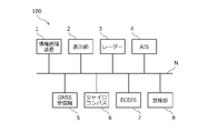
- FIG. 1 is a block diagram showing a configuration example of the ship monitoring system 100 according to the embodiment.
- the ship monitoring method according to the embodiment is realized in the ship monitoring system 100.
- the ship monitoring system 100 is a system for monitoring ships mounted on the ship and existing in the surroundings.
- the ship equipped with the ship monitoring system 100 is an example of the first ship, and is referred to as "own ship” in the following description. Further, the ship existing around the own ship is an example of the second ship, and is referred to as “another ship” in the following description.
- speed is a vector quantity representing speed and direction (so-called ship speed vector), and "speed” is a scalar quantity.
- the ship monitoring system 100 includes an information processing device 1, a display unit 2, a radar 3, an AIS4, a GNSS receiver 5, a gyro compass 6, an ECDIS7, and an alarm unit 8. These devices are connected to a network N such as a LAN, and can communicate with each other via a network.
- a network N such as a LAN
- the information processing device 1 is a computer including a CPU, RAM, ROM, non-volatile memory, an input / output interface, and the like.
- the CPU of the information processing apparatus 1 executes information processing according to a program loaded from the ROM or the non-volatile memory into the RAM.
- the program may be supplied via an information storage medium such as an optical disk or a memory card, or may be supplied via a communication network such as the Internet or a LAN.
- the display unit 2 is, for example, a display device with a touch sensor.
- the touch sensor detects the position indicated on the screen by a finger or the like. Not limited to the touch sensor, the indicated position may be input by a trackball or the like.
- Radar 3 emits radio waves around its own ship, receives the reflected waves, and generates echo data based on the received signals. Further, the radar 3 identifies the target from the echo data and generates target tracking data (TT data) indicating the position and speed of the target.
- TT data target tracking data
- AIS Automatic Identification System 4 receives AIS data from other ships or land controls existing around its own ship. Not limited to AIS, VDES (VHFDataExchangeSystem) may be used.
- the AIS data includes the positions and speeds of other ships.
- the GNSS receiver 5 detects the position of its own ship based on the radio waves received from the GNSS (Global Navigation Satellite System).
- the gyro compass 6 detects the direction of the ship. Not limited to the gyro compass, a GPS compass or a magnetic compass may be used.
- ECDIS Electronic Chart Display and Information System 7 acquires the position of its own ship from the GNSS receiver 5 and displays the position of its own ship on an electronic chart.
- the ECDIS 7 also displays the planned route of the ship on the electronic chart.
- a GNSS plotter may be used.
- the alarm unit 8 issues an alarm when there is a risk that the own ship will collide with another ship.
- the alarm unit 8 may be, for example, an alarm by display, or an alarm by sound or light.
- the display alarm may be given by the display unit 2. That is, the display unit 2 may also serve as the alarm unit 8.
- the information processing device 1 is an independent device, but the information processing device 1 is not limited to this, and may be integrated with other devices such as ECDIS 7. That is, the functional unit of the information processing device 1 may be realized by another device such as ECDIS 7.
- the display unit 2 is also an independent device, but the present invention is not limited to this, and the display unit of another device such as ECDIS 7 may be used as the display unit 2 for displaying the image generated by the information processing device 1. ..
- the set of the GNSS receiver 5 and the ECDIS 7 is an example of the first data generation unit, and generates the own ship data representing the position and speed of the own ship. Specifically, the GNSS receiver 5 detects the position of the own ship, and the ECDIS 7 detects the speed of the own ship from the time change of the position of the own ship.
- the speed of the own ship may be detected based on the direction of the own ship detected by the gyro compass 6 and the speed of the own ship detected by the speedometer (not shown).
- the radar 3 or AIS4 is an example of the second data generation unit, and generates data of another ship representing the position and speed of another ship.
- the TT data generated by the radar 3 corresponds to the data of another ship.
- the AIS data generated by AIS4 also corresponds to the data of other ships.
- FIG. 2 is a diagram showing an example of another ship management database built in the memory of the information processing device 1.
- Other ship data generated by radar 3 or AIS4 is registered in the other ship management database.
- the other ship management database includes fields such as "other ship identifier”, "position”, “speed”, and "direction”.
- the positions and directions of other ships detected by the radar 3 are converted to the same coordinate system as GNSS.
- FIG. 3 is a diagram showing a configuration example of the information processing apparatus 1 according to the embodiment, which realizes the ship monitoring method according to the embodiment.
- the information processing apparatus 1 includes a risk range specifying unit 11, a display control unit 12, and a size data holding unit 13.
- the risk range specifying unit 11 and the display control unit 12 are realized by the CPU of the information processing device 1 executing information processing according to a program.
- the size data holding unit 13 is built in the memory of the information processing device 1.
- the risk range specifying unit 11 determines the position and other of the own ship at each time point predicted from the own ship data and the other ship data when it is assumed that the own ship changes its course in an arbitrary direction and crosses the predicted course of the other ship. Based on the position of the ship, it is set in the warning area P set around the ship area occupied by the own ship or around the own ship and the ship area occupied by the other ship or around the other ship in the predicted course of the other ship.
- the risk range L that overlaps with the warning area P is specified (see FIG. 7A).
- the display control unit 12 causes the display unit 2 to display an OZT (Obstacle Zone by Target) including the risk range L specified by the risk range identification unit 11 (see FIG. 7B).
- OZT Industrial Zone by Target
- the size data includes the lengths L1 and L2 of the ship area S occupied by the own ship and the lengths PL1 and PL2 of the warning area P set around the own ship.
- the ship area S occupied by the own ship is an area representing the physical size of the own ship.
- the ship area S of the own ship is represented by a line segment from the front end to the rear end of the own ship.
- the length L1 is the length from the reference position RP of the own ship to the front end of the own ship
- the length L2 is the length from the reference position RP of the own ship to the rear end of the own ship.
- the reference position RP of the own ship corresponds to the antenna position of the GNSS receiver 5 (see FIG. 1).
- the risk value is set to 1 which is the maximum in the ship area S of the own ship.
- the warning area P set around the own ship is set in front of and behind the own ship.
- the warning area P of the own ship is represented by a line segment extending forward from the front end of the own ship and a line segment extending rearward from the rear end of the own ship.
- the length PL1 is the length from the front end of the own ship to the front end of the warning area P
- the length PL2 is the length from the rear end of the own ship to the rear end of the warning area P.
- the caution area P does not have to be set behind the own ship. That is, the length PL2 may be 0. Further, the caution area P may not be set in front of the own ship. That is, the length PL1 may be 0.
- the caution area P is set according to the area where the operator feels that the invasion of another ship is psychologically unfavorable, although physical contact with another ship does not occur.
- the alert area P can be likened to a personal space where a person feels uncomfortable when approached by another person.
- the risk value is set to 1 in the caution area P as well as the ship area S.
- the risk value may be set so that the risk value gradually decreases as the distance from the own ship increases in the caution area P.
- the ship area S and the warning area P of the own ship are represented by line segments in the front-rear direction, but the limitation is not limited to this, and the length in the width direction is also added to the ship area S and the warning area S of the own ship.
- the area P may be represented by a rectangular area.
- the ship area occupied by the other ship and the caution area set around the other ship are set.
- the length in the front-rear direction of the other ship for example, the length of the ship included in the AIS data may be used, or a predetermined length according to the ship type included in the AIS data may be used. Not limited to this, the length in the front-rear direction of another ship may be estimated from, for example, the echo data of the radar 3.
- the reference position of the other ship is, for example, a predetermined position such as the center of the ship area of the other ship.
- FIG. 6 is a diagram showing an example of a specific processing procedure executed by the risk range specifying unit 11.
- the information processing apparatus 1 functions as the risk range specifying unit 11 by executing the process shown in the figure according to the program.
- 7A and B are diagrams showing a calculation example and a display example of OZT.
- the risk range specifying unit 11 acquires the own ship data (S11), and calculates the predicted position of the own ship at each time point based on the acquired own ship data (S12).
- the calculation of the predicted position of the own ship is performed under the assumption that the own ship will change its course in any direction at the current position while maintaining the speed. That is, while the magnitude of the own ship speed vector is constant, the direction of the own ship speed vector changes to an arbitrary direction at the reference time point, and thereafter, it sails in a certain direction from the own ship position at the reference time point. Is assumed to continue. Therefore, the predicted position of the ship at each time point exists on a concentric circle centered on the position of the ship at the reference time. The radius of the circle is expressed by the product of the elapsed time from the reference time and the magnitude of the own ship speed vector.
- the predicted position of the ship at each time point is represented by multiple concentric circles calculated for each of multiple discrete time points. Not limited to this, the predicted position of the own ship at each time point may be expressed by a circular formula including the elapsed time from the reference time point (details will be described later).
- the predicted position of the own ship is calculated on the assumption that the speed of the own ship is constant, but the predicted position of the own ship is not limited to this, and the speed of the own ship changes with time. It may be treated as a variable. That is, if the predicted position of the own ship is obtained according to the elapsed time from the reference time, the speed of the own ship does not have to be constant. For example, the speed of the ship may gradually increase or decrease over time.
- the risk range specifying unit 11 acquires the data of the other ship (S13), and calculates the predicted position of the other ship at each time point based on the acquired data of the other ship (S14).
- the calculation of the predicted position of another ship is performed under the assumption that the other ship will maintain the speed from the current position and navigate. That is, it is assumed that the magnitude and direction of the speed vector of the other ship are constant and the navigation is continued from the position of the other ship at the reference time. Therefore, the predicted position of the other ship at each time point exists on a straight line extending the speed vector of the other ship passing through the position of the other ship at the reference time point.
- the predicted position of another ship at each time point is represented by a plurality of discrete points arranged on a straight line calculated for each of the multiple discrete time points.
- the predicted position of the other ship at each time point may be expressed by a linear function passing through the position of the other ship at the reference time point (details will be described later).
- the predicted position of the other ship is calculated on the assumption that the speed of the other ship is constant, but the predicted position is not limited to this, and at least one of the speed and the direction of the other ship is time. It may be treated as a variable that changes according to. That is, the speed of the other ship does not have to be constant as long as the predicted position of the other ship is obtained according to the elapsed time from the reference time. For example, the speed of another vessel may gradually increase or decrease over time. Further, the other ship may change the course in a predetermined direction or may turn at a predetermined ROT (Rate of Turn).
- ROT Rate of Turn
- the risk range specifying unit 11 calculates the separation distance between the predicted position of the own ship and the predicted position of another ship at each time point (S15).
- the risk range specifying unit 11 can use the circle representing the predicted position of the own ship at a certain point in time to display another ship at the same point. Select the position closest to the predicted position of and calculate the separation distance.
- the risk range specifying unit 11 acquires size data from the size data holding unit 13 (S16), and calculates a risk value indicating the risk of collision between the own ship and another ship based on the separation distance and the size data. (S17).
- the risk range specifying unit 11 sets the ship area S and the warning area P of the own ship using the size data of the own ship (see FIGS. 4 and 5), and sets the ship area BS of the other ship. It is set and it is determined whether or not the ship area BS of another ship is included in the ship area S or the caution area P of the own ship.
- the ship of the own ship is the distance L1 or less from the reference position RP of the own ship to the front end of the ship area S. It is determined that the area S includes the predicted position of another ship. Further, when the separation distance is larger than the distance L1 and is equal to or less than the distance L1 + PL1 from the reference position RP of the own ship to the front end of the warning area P, the warning area P of the own ship includes the predicted position of another ship. It is judged.
- the separation distance of the own ship is equal to or less than the distance L2 from the reference position RP of the own ship to the rear end of the ship area S. It is determined that the ship area S includes the predicted position of another ship. Further, when the separation distance is larger than the distance L2 and the distance from the reference position RP of the own ship to the rear end of the warning area P is L2 + PL2 or less, the predicted position of the other ship is included in the warning area P of the own ship. Is determined.
- Whether the predicted position of the own ship is in front of or behind the predicted course of another ship can be determined by the positive and negative signs of the separation distance.
- the distance between the point indicating the predicted position of the own ship and the front end or the rear end of the ship area BS of the other ship is set. You may ask.
- the distance between the point indicating the predicted position of the own ship and the front end or the rear end of the warning area BP of the other ship is set. You may ask.
- the risk range specifying unit 11 sets the risk value to 1 when the ship area S or the warning area P of the own ship includes the ship area BS of another ship, and minimizes the risk value when it is not included. It is set to 0 (see FIG. 5 (a)).
- the threshold value is set between 0 and 1, and when the ship area S of the own ship or the ship area BS of another ship is included in the caution area P, the risk value becomes equal to or higher than the threshold value.
- the risk value may be set so as to gradually decrease as the distance from the own ship increases (see FIG. 5 (b)).
- the risk value becomes equal to or higher than the threshold value.
- the calculation by the risk range specifying unit 11 may be performed as follows. Here, an example of calculating the position where the front end of the ship area of the own ship and the rear end of the ship area of another ship come into contact with each other will be described.
- Vo be the velocity vector of the own ship.
- Lof the length from the reference position of the own ship to the front end.
- the position of the front end of the ship area of the ship after the lapse of time t is the origin (0,0). It is represented by the circumference of the radius Vot + Lof centered on.
- V t be the velocity vector of the own ship.
- L tb The length from the reference position of another ship to the rear end.
- the position CP of the rear end of the ship area of the other ship after the lapse of time t is expressed by the following formula 1.
- V tx is the x component of V t
- V ty is the y component of V t .
- the risk range specifying unit 11 specifies the risk range L in which the risk value calculated in S17 is equal to or higher than the threshold value (S18).
- the front-back direction of the risk range L corresponds to the front-back direction of another ship.
- the risk value becomes equal to or higher than the threshold value when the ship area S of the own ship or the ship area BS of another ship is included in the warning area P. Therefore, as shown in FIG. 7A, the risk.
- the rear end LR of the range L is a position where the front end of the warning area P of the own ship comes into contact with the rear end of the ship area BS of another ship.
- the front end LF of the risk range L is a position where the rear end of the warning area P of the own ship comes into contact with the front end of the ship area BS of another ship.
- the risk range specifying unit 11 outputs the specified risk range L as the range of OZT to the display control unit 12, and ends the process. If there are a plurality of other ships, the processes S13 to S18 are executed for each of the plurality of other ships.
- the display control unit 12 displays OZT in the risk range L specified by the risk range specifying unit 11.
- the OZT has a shape extending in the same direction as the predicted course of another ship, for example, a rectangular shape with rounded corners having semicircles at both ends. Not limited to this, the OZT may have an elliptical shape or the like.
- the part between the front end LF and the rear end LR of the risk range L is a straight line extending along the predicted course of another ship.
- a predetermined safety separation distance is used for the distance between the straight line and the predicted course of another ship and the radius of the semicircle at both ends.
- the matching relationship between the own ship and another ship is not limited to the example of FIG. 7A, and as shown in FIG. 9, for example, in both the front end LF and the rear end LR of the risk range L, the warning area P of the own ship
- the front end may be in contact with the rear end of the ship area BS of another ship.
- the rear end LR of the risk range L is the rear end of the warning area P of the own ship.
- the front end LF of the risk range L may be a position where the front end of the warning area P of the own ship comes into contact with the rear end of the ship area BS of the other ship.
- the risk range specifying unit 11 determines whether or not the ship area S or the warning range P of the own ship overlaps with the ship area BS or the warning range BP of another ship, as shown in FIG. You may.
- the rear end LR of the risk range L is a position where the front end of the warning area P of the own ship comes into contact with the rear end of the warning area BP of another ship.
- the front end LF of the risk range L is a position where the rear end of the warning area P of the own ship comes into contact with the front end of the warning area BP of another ship.
- the risk range specifying unit 11 may determine whether or not the ship area S of the own ship overlaps with the ship area BS or the warning range BP of another ship without setting the warning area P of the own ship. ..
- the risk range L in which the ship area S or the warning area P of the own ship overlaps with the ship area BS or the warning area BP of the other ship is specified, the risk range L of the own ship and the other ship is specified. It is possible to improve the accuracy of predicting the risk of collision or approach.
- FIGS. 12A to 12C are diagrams showing a calculation example and a display example of OZT according to the first modification.
- the collision range L1 (see FIG. 12A) where the ship area S of the own ship and the ship area BS of the other ship overlap, and the warning area P of the own ship and the warning area BP of the other ship overlap.
- the approach range L2 (see FIG. 12B) is specified as the risk range.
- the rear end L1R of the collision range L1 is a position where the front end of the ship area S of the own ship comes into contact with the rear end of the ship area BS of another ship.
- the front end L1F of the collision range L1 is a position where the rear end of the ship area S of the own ship comes into contact with the front end of the ship area BS of another ship.
- the rear end L2R of the approach range L2 is a position where the front end of the warning area P of the own ship comes into contact with the rear end of the warning area BP of another ship.
- the front end L2F of the approach range L2 is a position where the rear end of the warning area P of the own ship comes into contact with the front end of the warning area BP of another ship.
- the display control unit 12 displays OZT1 related to the collision range L1 and OZT2 related to the approach range L2 on the screen of the display unit 2.
- OZT1 related to the collision range L1 is a zone where there is a high possibility that a collision between the own ship and another ship will occur in the future.
- OZT2 related to the approach range L2 is a zone in which the possibility of collision is not as high as that of OZT1, but the possibility that the own ship and another ship will approach each other in the future is high.
- OZT1 is included in OZT2.
- the display control unit 12 makes the display modes such as shading, color, and texture different from each other between the OZT1 related to the collision range L1 and the OZT2 related to the approach range L2. For example, the display control unit 12 displays OZT1 darker than OZT2. By creating each of OZT1 and 2 in a translucent manner and displaying them in an overlapping manner, OZT1 is displayed darker than OZT2.
- the risk range specifying unit 11 has a first risk range L3 (see FIG. 13A) in which the ship area S of the own ship overlaps with the ship area BS or the warning area BP of another ship, and the ship area S or the warning area P of the own ship.
- the second risk range L4 (see FIG. 13C) where the ship area BS of another ship overlaps with the ship area BS is specified as the risk range.
- the rear end L3R of the first risk range L3 is a position where the front end of the ship area S of the own ship comes into contact with the rear end of the warning area BP of another ship.
- the front end L3F of the first risk range L3 is a position where the rear end of the ship area S of the own ship comes into contact with the front end of the warning area BP of another ship.
- the rear end L4R of the second risk range L4 is a position where the front end of the warning area P of the own ship comes into contact with the rear end of the ship area BS of another ship.
- the front end L4F of the second risk range L4 is a position where the rear end of the warning area P of the own ship comes into contact with the front end of the ship area BS of another ship.
- the display control unit 12 displays the OZT3 related to the first risk range L3 and the OZT4 related to the second risk range L4 on the screen of the display unit 2.
- the OZT3 according to the first risk range L3 and the OZT4 according to the second risk range L4 partially overlap.
- the display control unit 12 makes the display mode such as shading, color, or texture different from each other between the overlapping portion OL and the other portion of OZT3 and 4. For example, the display control unit 12 displays the overlapping portion OL darker than the other portions. By creating each of OZT3 and 4 in a semi-transparent manner and displaying them in an overlapping manner, the overlapping portion OL is displayed darker than the other portions.
- the display is the same as that of the first modification, and it becomes easy for the user to grasp the degree of risk of collision or approach.
- FIG. 14 is a diagram for explaining size data according to the third modification.
- the size data includes not only the lengths L1 and L2 in the front-rear direction of the ship area S of the own ship and the lengths PL1 and PL2 in the front-rear direction of the caution area P, but also the lengths L3 and L3 in the width direction of the ship area S of the own ship.
- the lengths PL3 and PL4 in the width direction of L4 and the caution area P are included.
- the ship area S of the own ship is represented as a rectangular area.
- the length L3 is the length from the reference position RP of the own ship to the left end of the own ship
- the length L4 is the length from the reference position RP of the own ship to the right end of the own ship.
- the warning area P of the own ship is also represented as a rectangular area.
- the length PL3 is the length from the left end of the own ship to the left end of the warning area P
- the length PL4 is the length from the right end of the own ship to the right end of the warning area P.
- the length in the width direction may be set in the ship area BS and the caution area BP of the other ship as well as the own ship.
- a predetermined length according to the ship type included in the AIS may be used, or may be estimated from the echo data of the radar 3.
- the risk range specifying unit 11 sets the ship area S of the own ship and the ship area BS of the other ship, and sets the rectangular ship area S of the own ship and the ship area BS of the other rectangular ship. May be determined if they overlap. Further, the risk range specifying unit 11 sets the ship area S of the own ship, the ship area BS of the other ship, and the warning area BP, and the rectangular ship area S of the own ship and the ship area BS of the other rectangular ship. Alternatively, it may be determined whether or not the warning area BP overlaps.
- the risk range specifying unit 11 sets the ship area S and the warning area P of the own ship, the ship area BS and the warning area BP of the other ship, and has a rectangular shape with the ship area S or the warning area P of the own ship. It may be determined whether or not the shape overlaps with the ship area BS or the caution area BP of another ship.
- the risk range L is determined in consideration of the width of the ship area or the caution area, it is possible to improve the prediction accuracy of the risk of collision or approach between the own ship and another ship.
- 1 information processing device 2 display unit, 3 radar, 4 AIS, 5 GNSS receiver, 6 gyro compass, 7 ECDIS, 8 alarm unit, 11 risk range identification unit, 12 display control unit, 13 size data retention unit, 100 ship Monitoring system
Landscapes
- Engineering & Computer Science (AREA)
- Radar, Positioning & Navigation (AREA)
- Remote Sensing (AREA)
- Ocean & Marine Engineering (AREA)
- Chemical & Material Sciences (AREA)
- Combustion & Propulsion (AREA)
- Mechanical Engineering (AREA)
- Physics & Mathematics (AREA)
- General Physics & Mathematics (AREA)
- Automation & Control Theory (AREA)
- Traffic Control Systems (AREA)
Abstract
【課題】衝突ないし接近のリスクの予測精度の向上を図ることが可能な船舶監視システムを提供する。 【解決手段】船舶監視システムは、第1船舶の位置及び速度を表す第1船舶データを生成する第1データ生成部と、第2船舶の位置及び速度を表す第2船舶データを生成する第2データ生成部と、第1船舶が任意の方向に変針して第2船舶の予測針路を横切ると仮定したときの、第1船舶データ及び第2船舶データから予測される各時点の第1船舶の位置及び第2船舶の位置に基づいて、第2船舶の予測針路のうちの、前記第1船舶が占める船領域又は前記第1船舶の周囲に設定される警戒領域と、前記第2船舶が占める船領域又は前記第2船舶の周囲に設定される警戒領域とが重複するリスク範囲を特定するリスク範囲特定部と、リスク範囲にOZTを表示する表示部と、を備える。
Description
本発明は、船舶監視システム、船舶監視方法、情報処理装置、及びプログラムに関する。
従来、船舶同士が衝突するリスクを評価する種々の手法が存在する。例えば、非特許文献1には、OZT(Obstacle Zone by Target)を表示する手法が開示されている。
ところで、従来のOZTを表示する手法では、船舶を点とみなしてリスク計算を行っており、船舶の大きさを考慮していない。このため、OZTが表示される範囲の境界近傍では、船舶同士が異常接近する等の事態が起こり得る。
本発明は、上記課題に鑑みてなされたものであり、その主な目的は、衝突ないし接近のリスクの予測精度の向上を図ることが可能な、船舶監視システム、船舶監視方法、情報処理装置、及びプログラムを提供することにある。
上記課題を解決するため、本発明の一の態様の船舶監視システムは、第1船舶の位置及び速度を表す第1船舶データを生成する第1データ生成部と、第2船舶の位置及び速度を表す第2船舶データを生成する第2データ生成部と、前記第1船舶が任意の方向に変針して前記第2船舶の予測針路を横切ると仮定したときの、前記第1船舶データ及び前記第2船舶データから予測される各時点の前記第1船舶の位置及び前記第2船舶の位置に基づいて、前記第2船舶の予測針路のうちの、前記第1船舶が占める船領域又は前記第1船舶の周囲に設定される警戒領域と、前記第2船舶が占める船領域又は前記第2船舶の周囲に設定される警戒領域とが重複するリスク範囲を特定するリスク範囲特定部と、前記リスク範囲にOZTを表示する表示部と、を備える。
また、本発明の他の態様の船舶監視方法は、第1データ生成部により、第1船舶の位置及び速度を表す第1船舶データを生成し、第2データ生成部により、第2船舶の位置及び速度を表す第2船舶データを生成し、前記第1船舶が任意の方向に変針して前記第2船舶の予測針路を横切ると仮定したときの、前記第1船舶データ及び前記第2船舶データから予測される各時点の前記第1船舶の位置及び前記第2船舶の位置に基づいて、前記第2船舶の予測針路のうちの、前記第1船舶が占める船領域又は前記第1船舶の周囲に設定される警戒領域と、前記第2船舶が占める船領域又は前記第2船舶の周囲に設定される警戒領域とが重複するリスク範囲を特定し、表示部において、前記リスク範囲にOZTを表示させる。
また、本発明の他の態様の情報処理装置は、第1船舶が任意の方向に変針して第2船舶の予測針路を横切ると仮定したときの、前記第1船舶の位置及び速度を表す第1船舶データ並びに前記第2船舶の位置及び速度を表す第2船舶データから予測される各時点の前記第1船舶の位置及び前記第2船舶の位置に基づいて、前記第2船舶の予測針路のうちの、前記第1船舶が占める船領域又は前記第1船舶の周囲に設定される警戒領域と、前記第2船舶が占める船領域又は前記第2船舶の周囲に設定される警戒領域とが重複するリスク範囲を特定するリスク範囲特定部と、表示部において、前記リスク範囲にOZTを表示させる表示制御部と、を備える。
また、本発明の他の態様のプログラムは、第1船舶が任意の方向に変針して第2船舶の予測針路を横切ると仮定したときの、前記第1船舶の位置及び速度を表す第1船舶データ並びに前記第2船舶の位置及び速度を表す第2船舶データから予測される各時点の前記第1船舶の位置及び前記第2船舶の位置に基づいて、前記第2船舶の予測針路のうちの、前記第1船舶が占める船領域又は前記第1船舶の周囲に設定される警戒領域と、前記第2船舶が占める船領域又は前記第2船舶の周囲に設定される警戒領域とが重複するリスク範囲を特定すること、及び、表示部において、前記リスク範囲にOZT(Obstacle Zone by Target)を表示させること、をコンピュータに実行させる。
本発明によれば、衝突ないし接近のリスクの予測精度の向上を図ることが可能となる。
以下、本発明の実施形態について、図面を参照しながら説明する。
図1は、実施形態に係る船舶監視システム100の構成例を示すブロック図である。実施形態に係る船舶監視方法は、船舶監視システム100において実現される。船舶監視システム100は、船舶に搭載され、周囲に存在する船舶を監視するためのシステムである。
船舶監視システム100が搭載された船舶は、第1船舶の例であり、以下の説明では「自船」という。また、自船の周囲に存在する船舶は、第2船舶の例であり、以下の説明では「他船」という。
また、以下の説明において、「速度」は速さと方位を表すベクトル量(いわゆる、船速ベクトル)であるとし、「速さ」はスカラー量であるとする。
船舶監視システム100は、情報処理装置1、表示部2、レーダー3、AIS4、GNSS受信機5、ジャイロコンパス6、ECDIS7、及び警報部8を備えている。これらの機器は、例えばLAN等のネットワークNに接続されており、相互にネットワーク通信が可能である。
情報処理装置1は、CPU、RAM、ROM、不揮発性メモリ、及び入出力インターフェース等を含むコンピュータである。情報処理装置1のCPUは、ROM又は不揮発性メモリからRAMにロードされたプログラムに従って情報処理を実行する。
プログラムは、例えば光ディスク又はメモリカード等の情報記憶媒体を介して供給されてもよいし、例えばインターネット又はLAN等の通信ネットワークを介して供給されてもよい。
表示部2は、例えばタッチセンサ付き表示装置である。タッチセンサは、指等による画面内の指示位置を検出する。タッチセンサに限らず、トラックボール等により指示位置が入力されてもよい。
レーダー3は、自船の周囲に電波を発するとともにその反射波を受信し、受信信号に基づいてエコーデータを生成する。また、レーダー3は、エコーデータから物標を識別し、物標の位置及び速度を表す物標追跡データ(TTデータ)を生成する。
AIS(Automatic Identification System)4は、自船の周囲に存在する他船又は陸上の管制からAISデータを受信する。AISに限らず、VDES(VHF Data Exchange System)が用いられてもよい。AISデータは、他船の位置及び速度等を含んでいる。
GNSS受信機5は、GNSS(Global Navigation Satellite System)から受信した電波に基づいて自船の位置を検出する。ジャイロコンパス6は、自船の方位を検出する。ジャイロコンパスに限らず、GPSコンパス又は磁気コンパスが用いられてもよい。
ECDIS(Electronic Chart Display and Information System)7は、GNSS受信機5から自船の位置を取得し、電子海図上に自船の位置を表示する。また、ECDIS7は、電子海図上に自船の予定航路も表示する。ECDISに限らず、GNSSプロッタが用いられてもよい。
警報部8は、自船が他船と衝突するリスクがある場合に警報を発報する。警報部8は、例えば表示による警報であってもよいし、音又は光による警報であってもよい。表示による警報は、表示部2において行われてもよい。すなわち、表示部2が警報部8を兼ねてもよい。
本実施形態において、情報処理装置1は独立した装置であるが、これに限らず、ECDIS7等の他の装置と一体であってもよい。すなわち、情報処理装置1の機能部がECDIS7等の他の装置で実現されてもよい。
また、表示部2も独立した装置であるが、これに限らず、ECDIS7等の他の装置の表示部が、情報処理装置1により生成された画像を表示する表示部2として用いられてもよい。
本実施形態において、GNSS受信機5とECDIS7の組は、第1データ生成部の例であり、自船の位置及び速度を表す自船データを生成する。具体的には、GNSS受信機5が自船の位置を検出するとともに、ECDIS7が自船の位置の時間変化から自船の速度を検出する。
これに限らず、自船の速度は、ジャイロコンパス6により検出される自船の方位と、不図示の船速計により検出される自船の速さとに基づいて検出されてもよい。
また、レーダー3又はAIS4は、第2データ生成部の例であり、他船の位置及び速度を表す他船データを生成する。具体的には、レーダー3により生成されるTTデータが他船データに相当する。また、AIS4により生成されるAISデータも他船データに相当する。
図2は、情報処理装置1のメモリに構築される他船管理データベースの例を示す図である。他船管理データベースには、レーダー3又はAIS4により生成された他船データが登録される。
他船管理データベースは、「他船識別子」、「位置」、「速さ」、及び「方位」等のフィールドを含んでいる。なお、レーダー3により検出される他船の位置及び方位は、GNSSと同じ座標系に変換される。
図3は、実施形態に係る船舶監視方法を実現する、実施形態に係る情報処理装置1の構成例を示す図である。情報処理装置1は、リスク範囲特定部11、表示制御部12、及びサイズデータ保持部13を備えている。
リスク範囲特定部11及び表示制御部12は、情報処理装置1のCPUがプログラムに従って情報処理を実行することにより実現される。サイズデータ保持部13は、情報処理装置1のメモリに構築される。
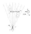
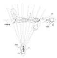
リスク範囲特定部11は、自船が任意の方向に変針して他船の予測針路を横切ると仮定したときの、自船データ及び他船データから予測される各時点の自船の位置及び他船の位置に基づいて、他船の予測針路のうちの、自船が占める船領域又は自船の周囲に設定される警戒領域Pと、他船が占める船領域又は他船の周囲に設定される警戒領域Pとが重複するリスク範囲Lを特定する(図7A参照)。
表示制御部12は、リスク範囲特定部11により特定されたリスク範囲Lを含むOZT(Obstacle Zone by Target)を、表示部2に表示させる(図7B参照)。
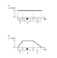
図4及び図5は、サイズデータ保持部13により保持される自船のサイズデータを説明するための図である。サイズデータは、自船が占める船領域Sの長さL1,L2と、自船の周囲に設定される警戒領域Pの長さPL1,PL2と、を含んでいる。
自船が占める船領域Sは、自船の物理的な大きさを表す領域である。本実施形態では、自船の船領域Sは、自船の前端から後端までの線分で表される。長さL1は、自船の基準位置RPから自船の前端までの長さであり、長さL2は、自船の基準位置RPから自船の後端までの長さである。自船の基準位置RPは、GNSS受信機5(図1参照)のアンテナ位置に対応する。
自船の船領域S内に他船が存在する場合に、衝突が生じるとされる。図5に示すように、自船の船領域S内では、リスク値が最大の1とされる。
自船の周囲に設定される警戒領域Pは、自船の前方及び後方に設定される。本実施形態では、自船の警戒領域Pは、自船の前端から前方に延びる線分と、自船の後端から後方に延びる線分とで表される。長さPL1は、自船の前端から警戒領域Pの前端までの長さであり、長さPL2は、自船の後端から警戒領域Pの後端までの長さである。
なお、自船の後方に警戒領域Pが設定されなくてもよい。すなわち、長さPL2が0であってもよい。また、自船の前方に警戒領域Pが設定されなくてもよい。すなわち、長さPL1が0であってもよい。
警戒領域Pは、他船との物理的な接触は生じないものの、他船の侵入を心理的に好ましくないと操船者が感じる領域に準じて設定される。警戒領域Pは、人が他人に近づかれると不快に感じるパーソナルスペースに例えることができる。
本実施形態では、図5(a)に示すように、警戒領域Pでも、船領域Sと同様に、リスク値が最大の1とされる。これに限らず、図5(b)に示すように、警戒領域Pでは、自船から離れるほどリスク値が徐々に小さくなるように設定されてもよい。
なお、本実施形態では、自船の船領域Sと警戒領域Pは前後方向の線分で表されるが、これに限らず、幅方向の長さも加えて、自船の船領域Sと警戒領域Pを矩形領域で表してもよい。
他船についても、自船と同様に、他船が占める船領域及び他船の周囲に設定される警戒領域が設定される。他船の前後方向の長さには、例えばAISデータに含まれる船の長さが用いられてもよいし、AISデータに含まれる船種に応じた所定長さが用いられてもよい。これに限らず、他船の前後方向の長さは、例えばレーダー3のエコーデータから推定されてもよい。他船の基準位置は、例えば他船の船領域の中心等の所定位置とされる。
図6は、リスク範囲特定部11が実行する具体的な処理の手順例を示す図である。情報処理装置1は、同図に示す処理をプログラムに従って実行することによって、リスク範囲特定部11として機能する。図7A及び図Bは、OZTの計算例及び表示例を示す図である。
まず、リスク範囲特定部11は、自船データを取得し(S11)、取得した自船データに基づいて、各時点における自船の予測位置を算出する(S12)。
具体的には、自船の予測位置の算出は、自船が速さを維持しつつ現在位置で任意の方向に変針して航行するとの仮定のもとで行われる。すなわち、自船船速ベクトルの大きさは一定である一方、自船船速ベクトルの向きは基準時点で任意の方向に変針し、それ以後は一定の方向で、基準時点の自船位置から航行を継続すると仮定される。したがって、各時点における自船の予測位置は、基準時点の自船位置を中心とする同心円上に存在する。円の半径は、基準時点からの経過時間と自船船速ベクトルの大きさとの積で表される。
各時点における自船の予測位置は、離散的な複数の時点のそれぞれについて算出された複数の同心円で表される。これに限らず、各時点における自船の予測位置は、基準時点からの経過時間を含む円の式で表されてもよい(詳細は後述する)。
なお、本実施形態では、自船の速さが一定であるとの仮定のもとで自船の予測位置が算出されたが、これに限らず、自船の速さは時間に応じて変化する変数として扱われてもよい。すなわち、基準時点からの経過時間に応じた自船の予測位置が求められるのであれば、自船の速さは一定でなくてもよい。例えば、自船の速さは時間の経過とともに徐々に増加又は減少してもよい。
次に、リスク範囲特定部11は、他船データを取得し(S13)、取得した他船データに基づいて、各時点における他船の予測位置を算出する(S14)。
具体的には、他船の予測位置の算出は、他船が現在位置から速度を維持して航行するとの仮定のもとで行われる。すなわち、他船船速ベクトルの大きさ及び向きが一定で、基準時点の他船位置から航行を継続すると仮定される。したがって、各時点における他船の予測位置は、基準時点の他船位置を通る、他船船速ベクトルを延長した直線上に存在する。
各時点における他船の予測位置は、離散的な複数の時点のそれぞれについて算出された、直線上に並ぶ離散的な複数の点で表される。これに限らず、各時点における他船の予測位置は、基準時点の他船位置を通る一次関数で表されてもよい(詳細は後述する)。
なお、本実施形態では、他船の速度が一定であるとの仮定のもとに他船の予測位置が算出されたが、これに限らず、他船の速さ及び方向の少なくとも一方が時間に応じて変化する変数として扱われてもよい。すなわち、基準時点からの経過時間に応じた他船の予測位置が求められるのであれば、他船の速度は一定でなくてもよい。例えば、他船の速さは時間の経過とともに徐々に増加又は減少してもよい。また、他船は所定の方向に変針してもよいし、所定のROT(Rate of Turn)で旋回してもよい。
次に、リスク範囲特定部11は、各時点における自船の予測位置と他船の予測位置との離隔距離を算出する(S15)。
上述したように、或る時点の自船の予測位置は円で表されるので、リスク範囲特定部11は、或る時点の自船の予測位置を表す円の中から、同時点の他船の予測位置に最も近い位置を選択して、離隔距離を算出する。
次に、リスク範囲特定部11は、サイズデータ保持部13からサイズデータを取得し(S16)、離隔距離及びサイズデータに基づいて、自船と他船とが衝突するリスクを表すリスク値を算出する(S17)。
図7Aの例では、リスク範囲特定部11は、自船のサイズデータを用いて自船の船領域S及び警戒領域Pを設定し(図4及び図5参照)、他船の船領域BSを設定して、自船の船領域S又は警戒領域P内に他船の船領域BSが含まれるか否か判定する。
例えば、自船の予測位置が他船の予測針路の手前にあるときは、離隔距離が、自船の基準位置RPから船領域Sの前端までの距離L1以下である場合に、自船の船領域Sに他船の予測位置が含まれると判定される。また、離隔距離が、距離L1より大きく、且つ自船の基準位置RPから警戒領域Pの前端までの距離L1+PL1以下である場合に、自船の警戒領域Pに他船の予測位置が含まれると判定される。
一方、自船の予測位置が他船の予測針路の奥にあるときは、離隔距離が、自船の基準位置RPから船領域Sの後端までの距離L2以下である場合に、自船の船領域Sに他船の予測位置が含まれると判定される。また、離隔距離が、距離L2より大きく、且つ自船の基準位置RPから警戒領域Pの後端までの距離L2+PL2以下である場合に、自船の警戒領域Pに他船の予測位置が含まれると判定される。
自船の予測位置が他船の予測針路の手前にあるか奥にあるかは、離隔距離の正負の符号により判別することができる。
図7Aに示すように、他船の船領域BS又は警戒領域BPを設定する場合には、自船の予測位置を表す点と、他船の船領域BSの前端又は後端との離隔距離を求めてもよい。図8に示すように、他船の船領域BS及び警戒領域BPを設定する場合には、自船の予測位置を表す点と、他船の警戒領域BPの前端又は後端との離隔距離を求めてもよい。
リスク範囲特定部11は、自船の船領域S又は警戒領域P内に他船の船領域BSが含まれる場合にはリスク値を最大の1とし、含まれない場合にはリスク値を最小の0とする(図5(a)参照)。閾値は0~1の間で定められ、自船の船領域S又は警戒領域P内に他船の船領域BSが含まれる場合に、リスク値が閾値以上となる。
これに限らず、警戒領域Pでは、自船から離れるほどリスク値が徐々に小さくなるように設定されてもよく(図5(b)参照)、この場合、自船の警戒領域P内に他船の船領域BSが含まれ、且つ自船の船領域Sにある程度近づいた場合に、リスク値が閾値以上となる。
なお、リスク範囲特定部11による計算は、次のように行われてもよい。ここでは、自船の船領域の前端と他船の船領域の後端とが当接する位置を算出する例を挙げて説明する。
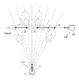
図8に示すように、t=0のときの自船の初期位置(すなわち、自船の現在位置)を、xy平面の原点(0,0)とする。また、自船の速度ベクトルをVoとする。また、自船の基準位置から前端までの長さをLof(図4のL1に相当)とする。自船が現在位置で瞬時に360度全方位に変針可能で、船速一定のまま航行すると仮定したとき、時間t経過後の自船の船領域の前端の位置は、原点(0,0)を中心とする半径Vot+Lofの円周で表される。
一方、t=0のときの他船の初期位置(すなわち、他船の現在位置)を、xy平面の(x,y)とする。また、自船の速度ベクトルをVtとする。また、他船の基準位置から後端までの長さをLtbとする。他船が現在位置から針路と船速の両方を一定としたまま航行すると仮定したとき、時間t経過後の他船の船領域の後端の位置CPは、下記数式1で表される。ここで、VtxはVtのx成分であり、VtyはVtのy成分である。

ここで、自船の船領域の前端と他船の船領域の後端とが当接する場合とは、自船の船領域の前端の位置を表す半径Vot+Lofの円周上に、他船の船領域の後端の位置CPが位置する場合であるため、下記数式2が成立する。

この数式2を解くことで、自船の船領域の前端と他船の船領域の後端とが当接する時間tを算出することができる。さらに、算出された時間tを上記数式1に代入することで、自船の船領域の前端と他船の船領域の後端とが当接する位置を算出することができる。
ここでは、自船の船領域の前端と他船の船領域の後端とが当接する位置を算出する場合について説明したが、図11に示すような自船の警戒領域Pの前端が他船の警戒領域BPの後端に当接する場合など、他の場合も同様に計算することができる。
図6の説明に戻る。リスク範囲特定部11は、上記S17で算出されたリスク値が閾値以上となるリスク範囲Lを特定する(S18)。リスク範囲Lの前後方向は、他船の前後方向と対応する。
上述したように、本実施形態では、自船の船領域S又は警戒領域P内に他船の船領域BSが含まれる場合にリスク値が閾値以上となるので、図7Aに示すように、リスク範囲Lの後端LRは、自船の警戒領域Pの前端が、他船の船領域BSの後端に当接する位置となる。リスク範囲Lの前端LFは、自船の警戒領域Pの後端が、他船の船領域BSの前端に当接する位置となる。
リスク範囲特定部11は、特定されたリスク範囲LをOZTの範囲として表示制御部12に出力し、処理を終了する。なお、複数の他船が存在する場合には、S13~S18の処理が複数の他船のそれぞれについて実行される。
図7Bの例では、表示制御部12は、リスク範囲特定部11により特定されたリスク範囲LにOZTを表示する。OZTは、他船の予測針路と同方向に延びた形状、例えば両端が半円の角丸長方形状を有している。これに限らず、OZTは、楕円形状などであってもよい。
OZTの縁のうち、リスク範囲Lの前端LFと後端LRとの間の部分は他船の予測針路に沿って延びる直線となっている。当該直線と他船の予測針路との間隔、及び両端の半円の半径には、予め定められた安全離隔距離が用いられる。
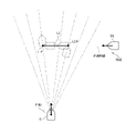
なお、自船と他船の見合い関係は、図7Aの例に限らず、例えば図9に示すように、リスク範囲Lの前端LFと後端LRの何れにおいても、自船の警戒領域Pの前端が他船の船領域BSの後端に当接する位置となる場合もある。また、図10に示すように、リスク範囲Lが2つ発生する場合に、他船から遠い方のリスク範囲Lでは、リスク範囲Lの後端LRは、自船の警戒領域Pの後端が他船の船領域BSの前端に当接する位置となり、リスク範囲Lの前端LFは、自船の警戒領域Pの前端が他船の船領域BSの後端に当接する位置となる場合もある。
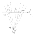
上記の例に限らず、リスク範囲特定部11は、図11に示すように、自船の船領域S又は警戒範囲Pが他船の船領域BS又は警戒範囲BPと重複するか否か判定してもよい。この例では、リスク範囲Lの後端LRは、自船の警戒領域Pの前端が他船の警戒領域BPの後端に当接する位置となる。リスク範囲Lの前端LFは、自船の警戒領域Pの後端が他船の警戒領域BPの前端に当接する位置となる。
また、リスク範囲特定部11は、自船の警戒領域Pを設定せずに、自船の船領域Sが、他船の船領域BS又は警戒範囲BPと重複するか否か判定してもよい。
以上に説明した実施形態によれば、自船の船領域S又は警戒領域Pと、他船の船領域BS又は警戒領域BPとが重複するリスク範囲Lを特定するので、自船と他船の衝突ないし接近のリスクの予測精度の向上を図ることが可能となる。
[第1変形例]
以下、第1変形例について説明する。上記実施形態と重複する構成については、同番号を付すことで詳細な説明を省略することがある。
以下、第1変形例について説明する。上記実施形態と重複する構成については、同番号を付すことで詳細な説明を省略することがある。
図12A~図12Cは、第1変形例に係るOZTの計算例及び表示例を示す図である。リスク範囲特定部11は、自船の船領域Sと他船の船領域BSとが重複する衝突範囲L1(図12A参照)と、自船の警戒領域Pと他船の警戒領域BPとが重複する接近範囲L2(図12B参照)とを、リスク範囲として特定する。
図12Aに示すように、衝突範囲L1の後端L1Rは、自船の船領域Sの前端が他船の船領域BSの後端に当接する位置となる。衝突範囲L1の前端L1Fは、自船の船領域Sの後端が他船の船領域BSの前端に当接する位置となる。
図12Bに示すように、接近範囲L2の後端L2Rは、自船の警戒領域Pの前端が他船の警戒領域BPの後端に当接する位置となる。接近範囲L2の前端L2Fは、自船の警戒領域Pの後端が他船の警戒領域BPの前端に当接する位置となる。
表示制御部12は、衝突範囲L1に係るOZT1と、接近範囲L2に係るOZT2とを、表示部2の画面に表示する。
衝突範囲L1に係るOZT1は、自船と他船との衝突が将来的に発生する可能性が高いゾーンである。接近範囲L2に係るOZT2は、OZT1ほど衝突の可能性は高くないものの、自船と他船とが将来的に接近する可能性が高いゾーンである。OZT1は、OZT2に包含される。
表示制御部12は、衝突範囲L1に係るOZT1と接近範囲L2に係るOZT2とで、濃淡、色、又はテクスチャ等の表示態様を互いに異ならせる。例えば、表示制御部12は、OZT1をOZT2よりも濃く表示する。OZT1,2のそれぞれを半透明で作成し、それらを重ねて表示することで、OZT1がOZT2よりも濃く表示される。
これによれば、衝突範囲L1に係るOZT1と接近範囲L2に係るOZT2とが識別して表示されるので、衝突ないし接近のリスクの程度をユーザが把握することが容易となる。
[第2変形例]
以下、第2変形例について説明する。上記実施形態と重複する構成については、同番号を付すことで詳細な説明を省略することがある。
以下、第2変形例について説明する。上記実施形態と重複する構成については、同番号を付すことで詳細な説明を省略することがある。
図13A~図13Cは、第2変形例に係るOZTの計算例及び表示例を示す図である。リスク範囲特定部11は、自船の船領域Sと他船の船領域BS又は警戒領域BPとが重複する第1リスク範囲L3(図13A参照)と、自船の船領域S又は警戒領域Pと他船の船領域BSとが重複する第2リスク範囲L4(図13C参照)とを、リスク範囲として特定する。
図13Aに示すように、第1リスク範囲L3の後端L3Rは、自船の船領域Sの前端が他船の警戒領域BPの後端に当接する位置となる。第1リスク範囲L3の前端L3Fは、自船の船領域Sの後端が他船の警戒領域BPの前端に当接する位置となる。
図13Bに示すように、第2リスク範囲L4の後端L4Rは、自船の警戒領域Pの前端が他船の船領域BSの後端に当接する位置となる。第2リスク範囲L4の前端L4Fは、自船の警戒領域Pの後端が他船の船領域BSの前端に当接する位置となる。
表示制御部12は、第1リスク範囲L3に係るOZT3と、第2リスク範囲L4に係るOZT4とを、表示部2の画面に表示する。第1リスク範囲L3に係るOZT3と、第2リスク範囲L4に係るOZT4とは、部分的に重複する。
表示制御部12は、OZT3,4のうちの重複部分OLと他の部分とで、濃淡、色、又はテクスチャ等の表示態様を互いに異ならせる。例えば、表示制御部12は、重複部分OLを他の部分よりも濃く表示する。OZT3,4のそれぞれを半透明で作成し、それらを重ねて表示することで、重複部分OLが他の部分よりも濃く表示される。
これによれば、上記第1変形例と同様の表示となり、衝突ないし接近のリスクの程度をユーザが把握することが容易となる。
[第3変形例]
以下、第3変形例について説明する。上記実施形態と重複する構成については、同番号を付すことで詳細な説明を省略することがある。
以下、第3変形例について説明する。上記実施形態と重複する構成については、同番号を付すことで詳細な説明を省略することがある。
図14は、第3変形例に係るサイズデータを説明するための図である。サイズデータは、自船の船領域Sの前後方向の長さL1,L2及び警戒領域Pの前後方向の長さPL1,PL2だけでなく、自船の船領域Sの幅方向の長さL3,L4及び警戒領域Pの幅方向の長さPL3,PL4を含んでいる。
このため、自船の船領域Sは、矩形状の領域として表される。長さL3は、自船の基準位置RPから自船の左端までの長さであり、長さL4は、自船の基準位置RPから自船の右端までの長さである。
また、自船の警戒領域Pも、矩形状の領域として表される。長さPL3は、自船の左端から警戒領域Pの左端までの長さであり、長さPL4は、自船の右端から警戒領域Pの右端までの長さである。
他船についても、自船と同様に、他船の船領域BS及び警戒領域BPに幅方向の長さが設定されてもよい。他船の幅方向の長さは、例えばAISに含まれる船種に応じた所定の長さが用いられてもよいし、レーダー3のエコーデータから推定されてもよい。
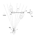
図15に示すように、本変形例では、リスク範囲特定部11は、矩形状の自船の船領域S又は警戒領域Pと、矩形状の他船の船領域BSとが重複するか否か判定して、リスク範囲Lを特定する。
他船が自船の前方を横切る見合い関係となる付近では、自船の警戒領域Pの左前端と他船の船領域の右後端とが当接する位置が存在する。このときの自船の針路方向と他船の予測針路との交点が、リスク範囲Lの後端LRとなる。
また、自船が他船の前方を横切る見合い関係となる付近では、自船の警戒領域Pの左後端と他船の船領域の左前端とが当接する位置が存在する。このときの自船の針路方向と他船の予測針路との交点が、リスク範囲Lの前端LFとなる。
これに限らず、リスク範囲特定部11は、自船の船領域Sと他船の船領域BSとを設定し、矩形状の自船の船領域Sと矩形状の他船の船領域BSとが重複するか判定してもよい。また、リスク範囲特定部11は、自船の船領域Sと他船の船領域BS及び警戒領域BPとを設定し、矩形状の自船の船領域Sと矩形状の他船の船領域BS又は警戒領域BPとが重複するか判定してもよい。
また、リスク範囲特定部11は、自船の船領域S及び警戒領域Pと他船の船領域BS及び警戒領域BPとを設定し、矩形状の自船の船領域S又は警戒領域Pと矩形状の他船の船領域BS又は警戒領域BPとが重複するか判定してもよい。
これによれば、船領域又は警戒領域の幅も考慮してリスク範囲Lが決定されるので、自船と他船との衝突ないし接近のリスクの予測精度の向上を図ることが可能となる。
以上、本発明の実施形態について説明したが、本発明は以上に説明した実施形態に限定されるものではなく、種々の変更が当業者にとって可能であることはもちろんである。
1 情報処理装置、2 表示部、3 レーダー、4 AIS、5 GNSS受信機、6 ジャイロコンパス、7 ECDIS、8 警報部、11 リスク範囲特定部、12 表示制御部、13 サイズデータ保持部、100 船舶監視システム
Claims (14)
- 第1船舶の位置及び速度を表す第1船舶データを生成する第1データ生成部と、
第2船舶の位置及び速度を表す第2船舶データを生成する第2データ生成部と、
前記第1船舶が任意の方向に変針して前記第2船舶の予測針路を横切ると仮定したときの、前記第1船舶データ及び前記第2船舶データから予測される各時点の前記第1船舶の位置及び前記第2船舶の位置に基づいて、前記第2船舶の予測針路のうちの、前記第1船舶が占める船領域又は前記第1船舶の周囲に設定される警戒領域と、前記第2船舶が占める船領域又は前記第2船舶の周囲に設定される警戒領域とが重複するリスク範囲を特定するリスク範囲特定部と、
前記リスク範囲にOZT(Obstacle Zone by Target)を表示する表示部と、
を備える、船舶監視システム。 - 前記リスク範囲の後端は、前記第1船舶が占める船領域の前端又は前記第1船舶の周囲に設定される警戒領域の前端が、前記第2船舶が占める船領域の後端又は前記第2船舶の周囲に設定される警戒領域の後端に当接する位置である、
請求項1に記載の船舶監視システム。 - 前記リスク範囲の前端は、前記第1船舶が占める船領域の後端又は前記第1船舶の周囲に設定される警戒領域の後端が、前記第2船舶が占める船領域の前端又は前記第2船舶の周囲に設定される警戒領域の前端に当接する位置である、
請求項1または2に記載の船舶監視システム。 - 前記リスク範囲の後端は、前記第1船舶が占める船領域の後端又は前記第1船舶の周囲に設定される警戒領域の後端が、前記第2船舶が占める船領域の前端又は前記第2船舶の周囲に設定される警戒領域の前端に当接する位置である、
請求項1に記載の船舶監視システム。 - 前記リスク範囲の前端は、前記第1船舶が占める船領域の前端又は前記第1船舶の周囲に設定される警戒領域の前端が、前記第2船舶が占める船領域の後端又は前記第2船舶の周囲に設定される警戒領域の後端に当接する位置である、
請求項1、2または4に記載の船舶監視システム。 - 前記リスク範囲特定部は、前記第1船舶が現在位置で任意の方向に変針して航行すると仮定したときの各方向における前記第1船舶が占める船領域の前端若しくは後端又は前記第1船舶の周囲に設定される警戒領域の前端若しくは後端と、前記第2船舶が占める船領域の前端若しくは後端又は前記第2船舶の周囲に設定される警戒領域の前端若しくは後端とが一致する時間を算出するための計算式に基づいて、前記リスク範囲を特定する、
請求項1ないし5の何れかに記載の船舶監視システム。 - 前記リスク範囲特定部は、前記第1船舶が占める船領域が前記第2船舶が占める船領域に重複する衝突範囲と、前記第1船舶の周囲に設定される警戒領域が前記第2船舶が占める船領域又は前記第2船舶の周囲に設定される警戒領域に重複する接近範囲とを、前記リスク範囲として特定し、
前記表示部は、前記衝突範囲に表示する前記OZTの表示態様と、前記接近範囲に表示する前記OZTの表示態様とを互いに異ならせる、
請求項1ないし6の何れかに記載の船舶監視システム。 - 前記リスク範囲特定部は、前記第1船舶が占める船領域が前記第2船舶が占める船領域又は前記第2船舶の周囲に設定される警戒領域に重複する第1リスク範囲と、前記第1船舶が占める船領域又は前記第1船舶の周囲に設定される警戒領域が前記第2船舶が占める船領域に重複する第2リスク範囲とを、前記リスク範囲として特定し、
前記表示部は、前記第1リスク範囲に表示する前記OZT及び前記第2リスク範囲に表示する前記OZTの重複部分の表示態様と、非重複部分の表示態様とを互いに異ならせる、
請求項1ないし6の何れかに記載の船舶監視システム。 - 前記第1船舶が占める船領域、前記第1船舶の周囲に設定される警戒領域、前記第2船舶が占める船領域、及び前記第2船舶の周囲に設定される警戒領域の少なくとも1つは、所定の幅を有する、
請求項1ないし8の何れかに記載の船舶監視システム。 - 前記第1データ生成部は、前記第1船舶に搭載され、GNSS(Global Navigation Satellite System)から受信した電波に基づいて前記第1船舶の位置を検出するGNSS受信機を含む、
請求項1ないし9の何れかに記載の船舶監視システム。 - 前記第2データ生成部は、前記第1船舶に搭載され、前記第1船舶の周囲に発せられた電波の反射波を受信して生成されたエコーデータから前記第2船舶の位置及び速度を検出するレーダーを含む、
請求項1ないし10の何れかに記載の船舶監視システム。 - 第1データ生成部により、第1船舶の位置及び速度を表す第1船舶データを生成し、
第2データ生成部により、第2船舶の位置及び速度を表す第2船舶データを生成し、
前記第1船舶が任意の方向に変針して前記第2船舶の予測針路を横切ると仮定したときの、前記第1船舶データ及び前記第2船舶データから予測される各時点の前記第1船舶の位置及び前記第2船舶の位置に基づいて、前記第2船舶の予測針路のうちの、前記第1船舶が占める船領域又は前記第1船舶の周囲に設定される警戒領域と、前記第2船舶が占める船領域又は前記第2船舶の周囲に設定される警戒領域とが重複するリスク範囲を特定し、
表示部において、前記リスク範囲にOZT(Obstacle Zone by Target)を表示させる、
船舶監視方法。 - 第1船舶が任意の方向に変針して第2船舶の予測針路を横切ると仮定したときの、前記第1船舶の位置及び速度を表す第1船舶データ並びに前記第2船舶の位置及び速度を表す第2船舶データから予測される各時点の前記第1船舶の位置及び前記第2船舶の位置に基づいて、前記第2船舶の予測針路のうちの、前記第1船舶が占める船領域又は前記第1船舶の周囲に設定される警戒領域と、前記第2船舶が占める船領域又は前記第2船舶の周囲に設定される警戒領域とが重複するリスク範囲を特定するリスク範囲特定部と、
表示部において、前記リスク範囲にOZT(Obstacle Zone by Target)を表示させる表示制御部と、
を備える、情報処理装置。 - 第1船舶が任意の方向に変針して第2船舶の予測針路を横切ると仮定したときの、前記第1船舶の位置及び速度を表す第1船舶データ並びに前記第2船舶の位置及び速度を表す第2船舶データから予測される各時点の前記第1船舶の位置及び前記第2船舶の位置に基づいて、前記第2船舶の予測針路のうちの、前記第1船舶が占める船領域又は前記第1船舶の周囲に設定される警戒領域と、前記第2船舶が占める船領域又は前記第2船舶の周囲に設定される警戒領域とが重複するリスク範囲を特定すること、及び、
表示部において、前記リスク範囲にOZT(Obstacle Zone by Target)を表示させること、
をコンピュータに実行させるためのプログラム。
Priority Applications (4)
| Application Number | Priority Date | Filing Date | Title |
|---|---|---|---|
| JP2022565130A JP7754843B2 (ja) | 2020-11-26 | 2021-10-25 | 船舶監視システム、船舶監視方法、情報処理装置、及びプログラム |
| EP21897583.7A EP4253219A4 (en) | 2020-11-26 | 2021-10-25 | Ship monitoring system, ship monitoring method, information processing device, and program |
| CN202180075634.1A CN116438110A (zh) | 2020-11-26 | 2021-10-25 | 船舶监视系统、船舶监视方法、信息处理装置以及程序 |
| US18/201,797 US12451016B2 (en) | 2020-11-26 | 2023-05-25 | Ship monitoring system, ship monitoring method, and information processing device |
Applications Claiming Priority (2)
| Application Number | Priority Date | Filing Date | Title |
|---|---|---|---|
| JP2020-195776 | 2020-11-26 | ||
| JP2020195776 | 2020-11-26 |
Related Child Applications (1)
| Application Number | Title | Priority Date | Filing Date |
|---|---|---|---|
| US18/201,797 Continuation-In-Part US12451016B2 (en) | 2020-11-26 | 2023-05-25 | Ship monitoring system, ship monitoring method, and information processing device |
Publications (1)
| Publication Number | Publication Date |
|---|---|
| WO2022113606A1 true WO2022113606A1 (ja) | 2022-06-02 |
Family
ID=81755785
Family Applications (1)
| Application Number | Title | Priority Date | Filing Date |
|---|---|---|---|
| PCT/JP2021/039313 Ceased WO2022113606A1 (ja) | 2020-11-26 | 2021-10-25 | 船舶監視システム、船舶監視方法、情報処理装置、及びプログラム |
Country Status (5)
| Country | Link |
|---|---|
| US (1) | US12451016B2 (ja) |
| EP (1) | EP4253219A4 (ja) |
| JP (1) | JP7754843B2 (ja) |
| CN (1) | CN116438110A (ja) |
| WO (1) | WO2022113606A1 (ja) |
Cited By (4)
| Publication number | Priority date | Publication date | Assignee | Title |
|---|---|---|---|---|
| US20240087459A1 (en) * | 2021-05-26 | 2024-03-14 | Furuno Electric Co., Ltd. | Ship monitoring device, ship monitoring method and a non-transitory computer-readable medium |
| WO2024262223A1 (ja) * | 2023-06-21 | 2024-12-26 | 古野電気株式会社 | 航行支援装置、航行支援方法、及びプログラム |
| CN119225270A (zh) * | 2024-11-28 | 2024-12-31 | 思创数码科技股份有限公司 | 一种基于plc的船舶自动调度方法及系统 |
| TWI921173B (zh) | 2025-04-24 | 2026-04-01 | 國立臺灣海洋大學 | 船舶異常行為偵測總成 |
Citations (3)
| Publication number | Priority date | Publication date | Assignee | Title |
|---|---|---|---|---|
| KR101976403B1 (ko) * | 2018-03-08 | 2019-08-28 | 주식회사 삼우이머션 | 해상을 운항하는 선박의 안전항로 제공 장치 |
| JP2020060886A (ja) * | 2018-10-09 | 2020-04-16 | 株式会社日本海洋科学 | 避航支援装置 |
| JP2020095333A (ja) * | 2018-12-10 | 2020-06-18 | 国立研究開発法人 海上・港湾・航空技術研究所 | 妨害ゾーン判断方法、移動体用システム及び妨害ゾーン表示方法 |
Family Cites Families (14)
| Publication number | Priority date | Publication date | Assignee | Title |
|---|---|---|---|---|
| JP2786809B2 (ja) * | 1994-03-08 | 1998-08-13 | 株式会社トキメック | 船舶用航行支援装置 |
| US6408248B1 (en) * | 2000-07-11 | 2002-06-18 | Northrop Grumman Corporation | Apparatus and method for providing accurate boundaries of predicted areas of danger for collision avoidance |
| JP4327000B2 (ja) * | 2004-04-02 | 2009-09-09 | 古野電気株式会社 | 相手船動静監視装置 |
| BR112013029892A2 (pt) * | 2011-05-21 | 2016-12-20 | Macrogenics Inc | polipeptídeo, molécula de ligação a antígeno, diacorpo e uso de uma porção polipeptídica de uma proteína de ligação a soro desimunizada |
| JP6953108B2 (ja) * | 2015-09-08 | 2021-10-27 | 古野電気株式会社 | 情報表示装置及び情報表示方法 |
| JP6618562B2 (ja) * | 2018-03-22 | 2019-12-11 | 東京計器株式会社 | 船舶用航行支援装置 |
| JP7080320B2 (ja) * | 2018-06-27 | 2022-06-03 | 古野電気株式会社 | 衝突警報装置及び衝突警報方法 |
| JP6715899B2 (ja) * | 2018-09-05 | 2020-07-01 | 三菱電機株式会社 | 衝突回避装置 |
| US20200409929A1 (en) * | 2019-06-25 | 2020-12-31 | Rm Acquisition, Llc D/B/A Rand Mcnally | Cloud-coupled connected sensor data and telematics |
| JP7259172B2 (ja) * | 2020-03-16 | 2023-04-18 | 三井E&S造船株式会社 | 航路生成装置 |
| JP2021187422A (ja) * | 2020-06-05 | 2021-12-13 | 国立研究開発法人 海上・港湾・航空技術研究所 | 妨害ゾーン判断方法、移動体用システム及び妨害ゾーン表示方法 |
| CN111709633B (zh) * | 2020-06-09 | 2022-09-06 | 吉林大学 | 一种碰撞危险度确定方法、装置、设备以及可存储介质 |
| US11433885B1 (en) * | 2020-08-20 | 2022-09-06 | Zoox, Inc. | Collision detection for vehicles |
| US11794732B2 (en) * | 2020-11-05 | 2023-10-24 | Zoox, Inc. | Allocation of safety system resources based on probability of intersection |
-
2021
- 2021-10-25 EP EP21897583.7A patent/EP4253219A4/en active Pending
- 2021-10-25 JP JP2022565130A patent/JP7754843B2/ja active Active
- 2021-10-25 WO PCT/JP2021/039313 patent/WO2022113606A1/ja not_active Ceased
- 2021-10-25 CN CN202180075634.1A patent/CN116438110A/zh active Pending
-
2023
- 2023-05-25 US US18/201,797 patent/US12451016B2/en active Active
Patent Citations (3)
| Publication number | Priority date | Publication date | Assignee | Title |
|---|---|---|---|---|
| KR101976403B1 (ko) * | 2018-03-08 | 2019-08-28 | 주식회사 삼우이머션 | 해상을 운항하는 선박의 안전항로 제공 장치 |
| JP2020060886A (ja) * | 2018-10-09 | 2020-04-16 | 株式会社日本海洋科学 | 避航支援装置 |
| JP2020095333A (ja) * | 2018-12-10 | 2020-06-18 | 国立研究開発法人 海上・港湾・航空技術研究所 | 妨害ゾーン判断方法、移動体用システム及び妨害ゾーン表示方法 |
Non-Patent Citations (2)
| Title |
|---|
| IMAZU, HAYAMAFUKUTO, JUNJINUMANO, MASAYOSH: "Obstacle Zone by Targets and Its Display", THE JOURNAL OF JAPAN INSTITUTE OF NAVIGATION, vol. 107, 2002, pages 191 - 197 |
| See also references of EP4253219A4 |
Cited By (5)
| Publication number | Priority date | Publication date | Assignee | Title |
|---|---|---|---|---|
| US20240087459A1 (en) * | 2021-05-26 | 2024-03-14 | Furuno Electric Co., Ltd. | Ship monitoring device, ship monitoring method and a non-transitory computer-readable medium |
| US12542061B2 (en) * | 2021-05-26 | 2026-02-03 | Furuno Electric Co., Ltd. | Ship monitoring device, ship monitoring method and a non-transitory computer-readable medium |
| WO2024262223A1 (ja) * | 2023-06-21 | 2024-12-26 | 古野電気株式会社 | 航行支援装置、航行支援方法、及びプログラム |
| CN119225270A (zh) * | 2024-11-28 | 2024-12-31 | 思创数码科技股份有限公司 | 一种基于plc的船舶自动调度方法及系统 |
| TWI921173B (zh) | 2025-04-24 | 2026-04-01 | 國立臺灣海洋大學 | 船舶異常行為偵測總成 |
Also Published As
| Publication number | Publication date |
|---|---|
| EP4253219A1 (en) | 2023-10-04 |
| US12451016B2 (en) | 2025-10-21 |
| CN116438110A (zh) | 2023-07-14 |
| JP7754843B2 (ja) | 2025-10-15 |
| JPWO2022113606A1 (ja) | 2022-06-02 |
| US20230298470A1 (en) | 2023-09-21 |
| EP4253219A4 (en) | 2024-10-16 |
Similar Documents
| Publication | Publication Date | Title |
|---|---|---|
| JP7724234B2 (ja) | 船舶監視システム、船舶監視方法、情報処理装置、及びプログラム | |
| WO2022113606A1 (ja) | 船舶監視システム、船舶監視方法、情報処理装置、及びプログラム | |
| CN109476318A (zh) | 用于车辆的触觉通知系统 | |
| CN111352074B (zh) | 用于相对于车辆对声源进行定位的方法和系统 | |
| US12542061B2 (en) | Ship monitoring device, ship monitoring method and a non-transitory computer-readable medium | |
| US11372100B2 (en) | Radar object classification and communication using smart targets | |
| JP7724231B2 (ja) | 船舶監視システム、船舶監視方法、情報処理装置、及びプログラム | |
| JP7813722B2 (ja) | 船舶監視システム、船舶監視方法、情報処理装置、及びプログラム | |
| US20240096221A1 (en) | Ship monitoring device, ship monitoring method and a non-transitory computer-readable medium | |
| JP7842085B2 (ja) | 船舶監視システム、船舶監視方法、情報処理装置、及びプログラム | |
| US20260100132A1 (en) | Navigation assistance device, navigation assistance method, and non-transitory computer-readable recording medium | |
| JP7636957B2 (ja) | 操船支援システム、操船支援方法、情報処理装置、及びプログラム | |
| JP7813780B2 (ja) | 船舶監視システム、船舶監視方法、情報処理装置、及びプログラム | |
| JP7781866B2 (ja) | 船舶監視システム、船舶監視方法、情報処理装置、及びプログラム | |
| WO2022091646A1 (ja) | 船舶監視システム、船舶監視方法、情報処理装置、及びプログラム | |
| US20240109626A1 (en) | Ship monitoring system, ship monitoring method, and information processor | |
| JP7664079B2 (ja) | 船舶監視システム、船舶監視方法、情報処理装置、及びプログラム | |
| WO2022239401A1 (ja) | 船舶監視システム、船舶監視方法、情報処理装置、及びプログラム | |
| JP7748391B2 (ja) | 船舶監視システム、船舶監視方法、情報処理装置、及びプログラム |
Legal Events
| Date | Code | Title | Description |
|---|---|---|---|
| 121 | Ep: the epo has been informed by wipo that ep was designated in this application |
Ref document number: 21897583 Country of ref document: EP Kind code of ref document: A1 |
|
| ENP | Entry into the national phase |
Ref document number: 2022565130 Country of ref document: JP Kind code of ref document: A |
|
| NENP | Non-entry into the national phase |
Ref country code: DE |
|
| ENP | Entry into the national phase |
Ref document number: 2021897583 Country of ref document: EP Effective date: 20230626 |