WO2022113754A1 - 表示装置および船舶 - Google Patents
表示装置および船舶 Download PDFInfo
- Publication number
- WO2022113754A1 WO2022113754A1 PCT/JP2021/041562 JP2021041562W WO2022113754A1 WO 2022113754 A1 WO2022113754 A1 WO 2022113754A1 JP 2021041562 W JP2021041562 W JP 2021041562W WO 2022113754 A1 WO2022113754 A1 WO 2022113754A1
- Authority
- WO
- WIPO (PCT)
- Prior art keywords
- mode
- screen
- symbol
- display
- operation mode
- Prior art date
- Legal status (The legal status is an assumption and is not a legal conclusion. Google has not performed a legal analysis and makes no representation as to the accuracy of the status listed.)
- Ceased
Links
Images







Classifications
-
- B—PERFORMING OPERATIONS; TRANSPORTING
- B63—SHIPS OR OTHER WATERBORNE VESSELS; RELATED EQUIPMENT
- B63B—SHIPS OR OTHER WATERBORNE VESSELS; EQUIPMENT FOR SHIPPING
- B63B49/00—Arrangements of nautical instruments or navigational aids
-
- B—PERFORMING OPERATIONS; TRANSPORTING
- B63—SHIPS OR OTHER WATERBORNE VESSELS; RELATED EQUIPMENT
- B63H—MARINE PROPULSION OR STEERING
- B63H21/00—Use of propulsion power plant or units on vessels
- B63H21/21—Control means for engine or transmission, specially adapted for use on marine vessels
-
- B—PERFORMING OPERATIONS; TRANSPORTING
- B60—VEHICLES IN GENERAL
- B60K—ARRANGEMENT OR MOUNTING OF PROPULSION UNITS OR OF TRANSMISSIONS IN VEHICLES; ARRANGEMENT OR MOUNTING OF PLURAL DIVERSE PRIME-MOVERS IN VEHICLES; AUXILIARY DRIVES FOR VEHICLES; INSTRUMENTATION OR DASHBOARDS FOR VEHICLES; ARRANGEMENTS IN CONNECTION WITH COOLING, AIR INTAKE, GAS EXHAUST OR FUEL SUPPLY OF PROPULSION UNITS IN VEHICLES
- B60K35/00—Instruments specially adapted for vehicles; Arrangement of instruments in or on vehicles
- B60K35/20—Output arrangements, i.e. from vehicle to user, associated with vehicle functions or specially adapted therefor
- B60K35/21—Output arrangements, i.e. from vehicle to user, associated with vehicle functions or specially adapted therefor using visual output, e.g. blinking lights or matrix displays
-
- B—PERFORMING OPERATIONS; TRANSPORTING
- B63—SHIPS OR OTHER WATERBORNE VESSELS; RELATED EQUIPMENT
- B63H—MARINE PROPULSION OR STEERING
- B63H21/00—Use of propulsion power plant or units on vessels
- B63H21/20—Use of propulsion power plant or units on vessels the vessels being powered by combinations of different types of propulsion units
-
- G—PHYSICS
- G06—COMPUTING OR CALCULATING; COUNTING
- G06F—ELECTRIC DIGITAL DATA PROCESSING
- G06F3/00—Input arrangements for transferring data to be processed into a form capable of being handled by the computer; Output arrangements for transferring data from processing unit to output unit, e.g. interface arrangements
- G06F3/01—Input arrangements or combined input and output arrangements for interaction between user and computer
- G06F3/03—Arrangements for converting the position or the displacement of a member into a coded form
- G06F3/041—Digitisers, e.g. for touch screens or touch pads, characterised by the transducing means
- G06F3/0412—Digitisers structurally integrated in a display
-
- G—PHYSICS
- G06—COMPUTING OR CALCULATING; COUNTING
- G06F—ELECTRIC DIGITAL DATA PROCESSING
- G06F3/00—Input arrangements for transferring data to be processed into a form capable of being handled by the computer; Output arrangements for transferring data from processing unit to output unit, e.g. interface arrangements
- G06F3/01—Input arrangements or combined input and output arrangements for interaction between user and computer
- G06F3/048—Interaction techniques based on graphical user interfaces [GUI]
- G06F3/0481—Interaction techniques based on graphical user interfaces [GUI] based on specific properties of the displayed interaction object or a metaphor-based environment, e.g. interaction with desktop elements like windows or icons, or assisted by a cursor's changing behaviour or appearance
- G06F3/04817—Interaction techniques based on graphical user interfaces [GUI] based on specific properties of the displayed interaction object or a metaphor-based environment, e.g. interaction with desktop elements like windows or icons, or assisted by a cursor's changing behaviour or appearance using icons
-
- B—PERFORMING OPERATIONS; TRANSPORTING
- B60—VEHICLES IN GENERAL
- B60K—ARRANGEMENT OR MOUNTING OF PROPULSION UNITS OR OF TRANSMISSIONS IN VEHICLES; ARRANGEMENT OR MOUNTING OF PLURAL DIVERSE PRIME-MOVERS IN VEHICLES; AUXILIARY DRIVES FOR VEHICLES; INSTRUMENTATION OR DASHBOARDS FOR VEHICLES; ARRANGEMENTS IN CONNECTION WITH COOLING, AIR INTAKE, GAS EXHAUST OR FUEL SUPPLY OF PROPULSION UNITS IN VEHICLES
- B60K2360/00—Indexing scheme associated with groups B60K35/00 or B60K37/00 relating to details of instruments or dashboards
- B60K2360/16—Type of output information
- B60K2360/172—Driving mode indication
-
- B—PERFORMING OPERATIONS; TRANSPORTING
- B63—SHIPS OR OTHER WATERBORNE VESSELS; RELATED EQUIPMENT
- B63H—MARINE PROPULSION OR STEERING
- B63H21/00—Use of propulsion power plant or units on vessels
- B63H21/20—Use of propulsion power plant or units on vessels the vessels being powered by combinations of different types of propulsion units
- B63H2021/202—Use of propulsion power plant or units on vessels the vessels being powered by combinations of different types of propulsion units of hybrid electric type
- B63H2021/205—Use of propulsion power plant or units on vessels the vessels being powered by combinations of different types of propulsion units of hybrid electric type the second power unit being of the internal combustion engine type, or the like, e.g. a Diesel engine
-
- G—PHYSICS
- G06—COMPUTING OR CALCULATING; COUNTING
- G06F—ELECTRIC DIGITAL DATA PROCESSING
- G06F2203/00—Indexing scheme relating to G06F3/00 - G06F3/048
- G06F2203/041—Indexing scheme relating to G06F3/041 - G06F3/045
Definitions
- the present invention relates to a display device for ships.
- a hybrid system for ships equipped with a motor in addition to an engine is known as a power source for ships (see, for example, Patent Document 1).
- the operating state of the hybrid system for ships includes, for example, a state in which the propulsion unit of the ship is driven by one or both of the engine and the motor, a state in which the motor generates power by the engine, and a state in which the kinetic energy of the ship is regenerated by the motor. Etc. are included.
- An object of the present invention is to provide a technique that allows an occupant to easily grasp the operating state of a hybrid system in a ship equipped with the hybrid system.
- the exemplary display device of the present invention is a display device that displays the operating state of a hybrid system that drives a propulsion machine that propels a ship, and the display screen that displays the operating state constitutes the hybrid system. It includes a symbol representing a component and a linear portion that connects the plurality of symbols and changes the lighting state according to the operation mode of the hybrid system.
- the occupant can easily grasp the operating state of the hybrid system in the ship equipped with the hybrid system.
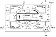
- FIG. 1 A diagram showing an example of a screen when an abnormality occurs in a hybrid system.
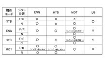
- the figure for demonstrating the operation mode display part A table showing the current operation mode and whether or not each operation mode can be selected for it.
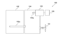
- FIG. 1 is a schematic view showing the configuration of a hybrid system 100 for ships according to an embodiment of the present invention.
- the hybrid system 100 is provided on the ship.
- the hybrid system 100 drives a propulsion machine 101 that propels a ship.
- the propulsion machine 101 is a propeller.
- the hybrid system 100 includes an engine 102, a motor 103, and a power transmission device 104.
- the engine 102 and the motor 103 are drive sources for rotating the propulsion machine 101.
- the engine 102 is a known diesel engine for ships. In the hybrid system 100, the engine 102 functions as a main engine.
- the engine 102 includes a crankshaft 102a that rotates in response to a reciprocating motion of a piston (not shown).
- the crankshaft 102a is an output shaft of the engine 102.
- the motor 103 is connected to the battery 105.
- the motor output shaft 103a which is the output of the motor 103, can be rotationally driven. Further, by rotating the motor output shaft 103a by an external force, the motor 103 can function as a generator and the battery 105 can be charged.
- the power transmission device 104 includes a power transmission shaft and a clutch (not shown). By switching the clutch in the power transmission device 104, it is possible to switch to a plurality of types of power transmission states. In the present embodiment, by switching the clutch of the power transmission device 104, only the driving force of the engine 102 is transmitted to the propulsion machine 101, only the driving force of the motor 103 is transmitted to the propulsion machine 101, and the engine. It is possible to switch to a state in which the driving forces of the 102 and the motor 103 are combined and transmitted to the propulsion machine 101. Further, the power transmission device 104 can also obtain a state in which the power of the engine 102 is transmitted to the motor output shaft 103a by switching the clutch.
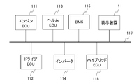
- FIG. 2 is a block diagram showing an electrical configuration of a hybrid system 100 for ships according to an embodiment of the present invention.
- the hybrid system 100 includes an engine ECU (Electronic Control Unit) 111, a drive ECU 112, a helm ECU 113, an inverter 114, a BMS (Battery Management System) 115, a hybrid ECU 116, and a display device 1. And.
- Each of these parts 111 to 116 and 1 is connected to the communication bus 117.
- the communication bus 117 is, for example, a CAN (Controller Area Network) bus.
- the engine ECU 111 controls the engine 102.
- the drive ECU 112 controls the power transmission device 104.
- the helm ECU 113 manages the user's ship maneuvering information such as the shift lever and the throttle lever.
- the inverter 114 is an inverter for driving control of the motor 103.
- the BMS 115 manages the battery 105.
- the BMS 115 for example, monitors the current / voltage and temperature of the battery 105, grasps the state of charge (SOC), and the like.
- the hybrid ECU 116 controls the motor 103 via the inverter 114.
- the hybrid ECU 116 controls the switching of the operation mode of the hybrid system 100 in cooperation with, for example, the engine ECU 111 and the drive ECU 112. As will be described later, the hybrid system 100 of the present embodiment has a plurality of operation modes.
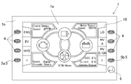
- FIG. 3 is a front view showing the configuration of the display device 1 according to the embodiment of the present invention.
- the display device 1 includes a display panel 1a and a bezel 1b that covers the outer periphery of the display panel 1a from the front side.
- the display panel 1a is configured by using, for example, a liquid crystal panel or an organic EL panel.
- the bezel 1b has a frame shape in a plan view from the front. In a plan view from the front of the display device 1, the inside of the bezel 1b is the screen area 10 on which the image is displayed.
- the display device 1 has a rectangular shape in a plan view from the front.
- the bezel 1b has a rectangular frame shape in a plan view from the front.
- the screen area 10 has a rectangular shape.
- these shapes may be changed as appropriate.
- the screen area 10 may have a circular shape, an elliptical shape, or the like.
- the shape of the bezel does not have to be a frame shape.
- the bezel may be arranged only on the left and right sides of the display panel 1a in a plan view from the front of the display device 1.
- a plurality of mode switching buttons 4 for performing an operation mode switching operation are arranged around the screen area 10.
- the mode switching button 4 is exposed to the front side through the opening provided in the bezel 1b.
- the mode switching button 4 is provided one by one corresponding to each operation mode.
- the operation mode may be switched by using the touch panel. In this case, the operation mode is switched by touching the predetermined position of the screen area 10.
- a screen for displaying the operating state is displayed.
- the types of screens that can be switched by the display device 1 include an aggregate screen that aggregates and displays the operating status, a data list screen that shows detailed information on the operating status, and the content of the warning that is occurring.
- a warning list screen to be displayed and an abnormality list screen displaying the contents of the abnormality being generated are included.
- the screen shown in FIG. 3 is an aggregate screen.
- the display device 1 is provided with a screen switching button 5 that enables switching between the plurality of types of screens.
- the screen switching button 5 is arranged around the screen area 10 in the same manner as the mode switching button 4. It should be noted that switching between a plurality of types of screens may be performed by using a touch panel. In this case, the screen is switched by touching the predetermined position of the screen area 10.
- the display device 1 is also provided with a close button 6.
- the close button 6 is also arranged around the screen area 10 in the same manner as the mode switching button 4 and the screen switching button 5. The details of the close button 6 will be described later.
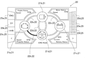
- FIG. 4 is a schematic diagram showing the configuration of the aggregation screen 20 that aggregates and displays the operating state.
- the aggregate screen 20 is a screen for displaying important information to the crew of the ship, and is a main screen mainly used in normal times.
- the aggregation screen 20 has a rectangular shape that is longer in the left-right direction than in the up-down direction.
- a symbol 21 representing a component constituting the hybrid system 100 and a plurality of symbols 21 are connected to each other to form a hybrid system.
- a linear portion 22 that changes the lighting state according to the operation mode of 100 is included. According to this configuration, the crew of the ship can easily grasp the current relationship between the plurality of components constituting the hybrid system 100 by looking at the aggregate screen 20.
- the propulsion machine 101 is a component included in the hybrid system 100. Further, there are a plurality of linear portions 22.
- the plurality of symbols 21 include a symbol 21a representing the engine 102, a symbol 21b representing the motor 103, a symbol 21c representing the battery 105, and a symbol 21d representing the propulsion machine 101. According to this, by looking at the aggregate screen 20, it is possible to easily grasp the current relationship between the main components constituting the hybrid system 100.
- the symbol 21a representing the engine 102 is the engine symbol 21a
- the symbol 21b representing the motor 103 is the motor symbol 21b
- the symbol 21c representing the battery 105 is the battery symbol 21c
- the symbol 21d representing the propulsion machine 101 is the propulsion machine symbol 21d. And each may be expressed.
- each of the four symbols 21a to 21d is arranged at the top of the diamond and is located at the center of the aggregation screen 20.
- the engine symbol 21a is arranged to the left of the center position of the aggregation screen 20.
- the motor symbol 21b is arranged above the center position of the aggregation screen 20.
- the battery symbol 21c is arranged to the right of the center position of the aggregation screen 20.
- the propulsion device symbol 21d is arranged below the center position of the aggregation screen 20.
- the linear portion 22 connecting the symbols 21 may be composed of a straight line, a curved line, or both a straight line and a curved line.
- the linear portion 22 is composed of a curved line.
- the plurality of linear portions 22 includes a first linear portion 22a, a second linear portion 22b, a third linear portion 22c, and a fourth linear portion 22d.
- the first linear portion 22a connects the engine symbol 21a and the motor symbol 21b.
- the second linear portion 22b connects the engine symbol 21a and the propulsion unit symbol 21d.
- the third linear portion 22c connects the motor symbol 21b and the battery symbol 21c.
- the fourth linear portion 22d connects the motor symbol 21b and the propulsion device symbol 21d.
- the aggregate screen 20 includes two additional linear portions 23 that do not change the lighting state according to the operation mode of the hybrid system 100.
- the additional linear portion 23 includes a first additional linear portion 23a connecting the motor symbol 21b and the propulsion symbol 21d, and a second additional linear portion 23b connecting the battery symbol 21c and the propulsion symbol 21d.
- the first additional linear portion 23a constitutes an arc portion of the same circle as the first linear portion 22a and the second linear portion 22b.
- the second additional linear portion 23b constitutes an arc portion of the same circle as the third linear portion 22c and the fourth linear portion 22d.
- first additional linear portion 23a and the second additional linear portion 23b may not be provided.
- first additional linear portion 23a may not be the additional linear portion but may be a linear portion whose lighting state is changed according to the operation mode of the hybrid system 100.
- the status display unit 24 includes an engine status display unit 24a, a motor status display unit 24b, a battery status display unit 24c, and a propulsion unit status display unit 24d.
- the engine status display unit 24a shows the status of the engine 102, which is a component of the hybrid system 100 corresponding to the engine symbol 21a.
- the motor status display unit 24b shows the status of the motor 103, which is a component of the hybrid system 100 corresponding to the motor symbol 21b.
- the battery status display unit 24c indicates the status of the battery 105, which is a component of the hybrid system 100 corresponding to the battery symbol 21c.
- the propulsion device status display unit 24d indicates the state of the propulsion device 101, which is a component of the hybrid system 100 corresponding to the propulsion device symbol 21d.
- the four status display units 24a to 24d are arranged so as to surround the four symbols 21a to 24 arranged in the central portion of the aggregation screen 20.
- the engine status display unit 24a has a character portion for displaying the rotation speed of the engine 102 and a surrounding line portion surrounding the character portion.
- the engine status display unit 24a is arranged in the vicinity of the engine symbol 21a.
- the engine status display unit 24a is arranged at the upper left portion of the aggregation screen 20. In the display content of the engine state, an engine state other than the engine speed such as the engine temperature may be displayed.
- the motor status display unit 24b has a character portion for displaying the rotation speed of the motor 103 and a surrounding line portion surrounding the character portion.
- the motor status display unit 24b is arranged in the vicinity of the motor symbol 21b.
- the motor status display unit 24b is arranged in the upper right portion of the aggregation screen 20. In the display content of the motor state, for example, the motor state other than the motor rotation speed such as the motor temperature may be displayed.
- the battery status display unit 24c has a character portion for displaying the current value and SOC of the battery 105, and a surrounding line portion surrounding the character portion.
- the battery status display unit 24c is arranged in the vicinity of the battery symbol 21c.
- the battery status display unit 24c is arranged at the lower right of the aggregation screen 20. In the display content of the battery status, for example, the battery current such as the battery voltage or the battery status other than the SOC may be displayed.
- the propulsion device status display unit 24d has a character portion for displaying the rotation speed of the propulsion device (propeller) 101 and a surrounding line portion surrounding the character portion.
- the propulsion device status display unit 24d is arranged in the vicinity of the propulsion device symbol 21d.
- the propulsion device status display unit 24d is arranged at the lower left of the aggregation screen 20.
- the propulsion machine state other than the propeller rotation speed may be displayed in the display content of the propulsion machine state.
- the aggregation screen 20 includes an operation mode display unit 25 that displays a plurality of types of operation modes provided in the hybrid system 100. According to this, the crew of the ship can easily select the operation mode used in the hybrid system 100 while looking at the aggregation screen 20.
- ENG Mode is an operation mode in which the engine 102 is used for navigation.
- MOT Mode is an operation mode in which the motor 103 is used for navigation.
- HYB Mode is an operation mode in which the motor 103 assists the cruising of the engine 102.
- LG Mode is an operation mode for charging the battery 105 using a land power source.
- HYB_A Mode is an operation mode in which the engine 102 is assisted by the motor 103 more strongly than in the case of "HYB Mode”.
- HYB_G Mode and “HYB_GN Mode” are operation modes in which the battery 105 is charged by using the engine 102 while cruising.
- the operation mode display unit 25 is arranged at the end of the aggregation screen 20.
- a plurality of buttons 4 which are provided side by side with the operation mode display unit 25 and enable selection of each operation mode are arranged. According to this, on a ship that is prone to shaking, the operation mode can be selected by using a plurality of independently provided buttons 4, so that the possibility of erroneously selecting the operation mode is reduced. can do.
- the plurality of buttons 4 are the above-mentioned plurality of mode switching buttons 4.
- the operation mode display unit 25 is also displayed on a screen other than the aggregation screen 20.
- the operation mode display unit 25 is displayed on all screens. That is, the operation mode display unit 25 is also included in the data list screen, the warning list screen, and the abnormality list screen.
- the ENG display 25a, the EV display 25b, and the HYB display 25c included in the operation mode display unit 25 are arranged at the left end portion of the aggregation screen 20. At the left end, the ENG display 25a, the EV display 25b, and the HYB display 25c are arranged in this order from top to bottom.
- Mode switching buttons 4 are arranged on the left side of the ENG display 25a, the EV display 25b, and the HYB display 25c, respectively.
- the LG display 25d, the HV_A display 25e, and the HV_G / GN display 25f included in the operation mode display unit 25 are arranged at the right end of the aggregation screen 20. At the right end, the LG display 25d, the HV_A display 25e, and the HV_G / GN display 25f are arranged in this order from top to bottom.
- Mode switching buttons 4 are arranged on the right side of the LG display 25d, the HV_A display 25e, and the HV_G / GN display 25f, respectively. By pressing the mode switching button 4 arranged on the right side of the LG display 25d, "LG Mode" can be selected.
- the aggregation screen 20 includes a current operation mode display area 26 indicating the currently selected operation mode.
- the current operation mode display area 26 is located between the battery status display unit 24c and the propulsion unit status display unit 24d in the left-right direction, and is arranged below the propulsion unit symbol 21d.
- FIG. 4 shows a state in which none of the operation modes displayed on the operation mode display unit 25 is selected, and "STB Mode” is displayed in the current operation mode display area 26.
- STB Mode is a standby mode that waits for the selection of the operation mode.
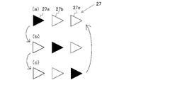
- FIG. 5A and 5B are diagrams for explaining the mode transitioning icon 27. As shown in FIG. 5A, during the transition of the operation mode, the mode transition icon 27 is displayed below the current operation mode display area 26. This allows the ship's crew to easily recognize that the operating mode is in transition.
- the mode transition icon 27 is composed of three triangular marks 27a, 27b, and 27c arranged in the left-right direction.
- the lighting positions of the marks 27a to 27c change at predetermined time intervals (for example, 0.5 seconds).
- the lighting position changes in the order of the first mark 27a, the second mark 27b, and the third mark 27c, and after the third mark 27c is lit, the lighting position returns to the first mark 27a.
- this lighting position change is repeated. This allows the ship's crew to more easily recognize that the operating mode is in transition.
- the colors of the linear portion 22 are the first energy flow indicating the energy flow for driving the propulsion machine 101 and the second energy flow indicating the energy flow for charging the battery 105. It is said to be a different color. According to this, the crew of the ship can immediately recognize the energy flow according to the operation mode by looking at the aggregation screen 20.
- the difference in the type of energy flow is displayed depending on the color, but the difference in energy flow is displayed by changing the lighting method (for example, blinking and non-blinking). May be good.
- the aggregation screen 20 in a plurality of operation modes will be illustrated, and the display of the energy flow will be described in detail.
- the background of the aggregate screen 20 is black.
- the color of the linear portion 22 is white.
- the color of the linear portion 22 indicating the first energy flow is green.
- the color of the linear portion 22 indicating the second energy flow is blue.
- FIG. 6A is a schematic diagram showing the aggregation screen 20 when "ENG Mode" is selected.
- "ENG Mode” the power of the engine 102 is transmitted to the propulsion machine 101. That is, the energy for driving the propulsion machine 101 flows from the engine 102 to the propulsion machine 101. Therefore, on the aggregation screen 20 in the case of "ENG Mode", the color of the second linear portion 22b connecting the engine symbol 21a and the propulsion unit symbol 21d is green.
- the colors of the first linear portion 22a, the third linear portion 22c, and the fourth linear portion 22d are white.
- FIG. 6B is a schematic diagram showing the aggregation screen 20 in the case of "ENG_N Mode".
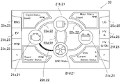
- "ENG_N Mode” is an operation mode when "ENG Mode” is selected on the display device 1 and the shift lever is in neutral. In this case, power is not transmitted to the propulsion machine 101 even when the engine 102 is in operation. That is, the energy for driving the propulsion machine 101 does not flow from the engine 102 to the propulsion machine 101. Therefore, in the aggregate screen 20 in the case of "ENG_N Mode", the color of the second linear portion 22b connecting the engine symbol 21a and the propulsion unit symbol 21d is the same as that of the other linear portions 22a, 22c, 22d. It becomes white.
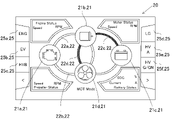
- FIG. 7A is a schematic diagram showing the aggregation screen 20 when "MOT Mode” is selected.
- the motor 103 obtains electric power from the battery 105 to rotate the motor output shaft 103a, and transmits the rotational power of the motor output shaft 103a to the propulsion machine 101. That is, the energy for driving the propulsion machine 101 flows from the battery 105 to the motor 103, and further flows from the motor 103 to the propulsion machine 101. Therefore, in the aggregation screen 20 in the case of "MOT Mode", the third linear portion 22c connecting the motor symbol 21b and the battery symbol 21c and the fourth linear portion connecting the motor symbol 21a and the propulsion unit symbol 21d. The color with 22d becomes green. The color of the first linear portion 22a and the second linear portion 22b is white.
- FIG. 7B is a schematic diagram showing the aggregation screen 20 in the case of "MOT_N Mode".
- “MOT_N Mode” is an operation mode when “MOT Mode” is selected on the display device 1 and the shift lever is in neutral. In this case, even if the motor 103 is supplied with electric power from the battery 105 and is in operation, the power is not transmitted to the propulsion machine 101. That is, the energy for driving the propulsion machine 101 does not flow from the motor 103 to the propulsion machine 101. Therefore, in the aggregate screen 20 in the case of "MOT_N Mode", only the third linear portion 22c connecting the motor symbol 21b and the battery symbol 21c is colored green, and the other linear portions 22a, 22b, and 22d are colored. Is white.
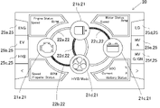
- FIG. 8A is a schematic diagram showing an aggregation screen 20 when "HYB Mode" is selected.
- the power of the engine 102 and the power of the motor 103 are combined and transmitted to the propulsion machine 101. Further, electric power for driving the motor 103 from the battery 105 is supplied to the motor 103. That is, the energy for driving the propulsion machine 101 flows from the engine 102 to the propulsion machine 101, and also flows from the battery 105 to the propulsion machine 101 via the motor 103. Therefore, in the aggregation screen 20 in the case of "HYB Mode", the second linear portion 22b connecting the engine symbol 21a and the propulsion symbol 21d and the third linear portion connecting the motor symbol 21b and the battery symbol 21c are connected. The color of the 22c and the fourth linear portion 22d connecting the motor symbol 21a and the propulsion unit symbol 21d is green. The color of the first linear portion 22a is white.
- the aggregation screen 20 in the case of "HYB_N Mode” has the same energy flow display as the aggregation screen 20 of "MOT_N Mode” shown in FIG. 7B. That is, in the aggregate screen 20 in the case of "HYB_N Mode", only the third linear portion 22c connecting the motor symbol 21b and the battery symbol 21c is colored green, and the other linear portions 22a, 22b, and 22d are colored. It is white.
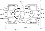
- FIG. 8B is a schematic diagram showing the aggregation screen 20 when "HV_A Mode” is selected.
- the motor 103 assists the engine 102 and the propulsion machine 101 rotates.
- the first linear portion 22a connecting the engine symbol 21a and the motor symbol 21b and the second linear portion connecting the engine symbol 21a and the propulsion symbol 21d are connected.
- the color of the portion 22b and the third linear portion 22c connecting the motor symbol 21b and the battery symbol 21c is green.
- the color of the fourth linear portion 22d is white.
- FIG. 9A is a schematic diagram showing an aggregation screen 20 when "HV_G Mode" is selected.
- “HV_G Mode” the power of the engine 102 is transmitted to the propulsion machine 101. Further, the motor output shaft 103a of the motor 103 is rotated by the power of the engine 102, and the electric power generated by the motor 103 is charged to the battery 105. That is, the energy for driving the propulsion machine 101 flows from the engine 102 to the propulsion machine 101. Further, energy for charging the battery 105 flows from the engine 102 to the battery 105 via the motor 103. Therefore, in the aggregate screen 20 in the case of "HV_G Mode", the color of the second linear portion 22b connecting the engine symbol 21a and the propulsion unit symbol 21d is green. The color of the first linear portion 22a connecting the engine symbol 21a and the motor symbol 21b and the third linear portion 22c connecting the motor symbol 21b and the battery symbol 21c is blue. The color of the fourth linear portion 22d is white.
- FIG. 9B is a schematic diagram showing the aggregation screen 20 in the case of "HV_GN Mode".
- "HV_GN Mode” is an operation mode when "HV_G Mode” is selected on the display device 1 and the shift lever is in neutral.
- power is not transmitted from the engine 102 to the propulsion machine 101.
- power is transmitted from the engine 102 to the motor 103, and the battery 105 is charged by the power generation of the motor 103. That is, the energy for driving the propulsion machine 101 does not flow from the engine 102 and the motor 103 to the propulsion machine 101.
- Energy for charging the battery 105 flows from the engine 102 to the battery 105 via the motor 103.
- the color of the second linear portion 22b connecting the engine symbol 21a and the propulsion unit symbol 21d is white instead of green. Further, the color of the first linear portion 22a connecting the engine symbol 21a and the motor symbol 21b and the third linear portion 22c connecting the motor symbol 21b and the battery symbol 21c is blue. The color of the fourth linear portion 22d is white. It was
- the display device 1 is provided on the aggregate screen 20 so that an icon 60 for notifying at least one of a warning and an abnormality occurring in the hybrid system 100 at present can be displayed.
- the crew of the ship can quickly recognize the warning or abnormality generated in the hybrid system 100.
- the icon 60 is displayed not only on the aggregation screen 20, but also on the data list screen, the warning list screen, and the abnormality list screen.
- a warning is issued when there is no abnormality in the hybrid system 100 at present, but there is a possibility that an abnormality will occur in the future.
- the state in which the warning is generated corresponds to, for example, the case where the temperature of the engine 102, the motor, or the like becomes higher than the preset threshold value, or the case where the SOC of the battery 105 becomes lower than the preset threshold value.
- the abnormality is generated when at least a part of the functions of the hybrid system 100 cannot be used.
- the abnormal state corresponds to, for example, a failure of various sensors, a failure of the engine 102, a failure of the motor 103, a failure of the power transmission device 104, and the like.
- FIG. 10 is a diagram showing an example of a screen when a warning occurs in the hybrid system 100.
- FIG. 11 is a diagram showing an example of a screen when an abnormality occurs in the hybrid system 100.
- FIGS. 10 and 11 as an example, it is assumed that a warning or an abnormality occurs when the aggregation screen 20 is displayed.
- the abnormality icon 60b is displayed in the upper right corner of the screen. Specifically, the anomaly icon 60b is displayed on the right side of the warning icon 60a. In this embodiment, the anomaly icon 60b is a red exclamation mark. However, the position, shape and color of the abnormality icon 60b may be changed as appropriate.
- the abnormality icon 60b may be configured to blink at predetermined time intervals in the same manner as the warning icon 60a. This makes it easier for the crew of the ship to recognize the occurrence of an abnormality.
- the abnormality icon 60b is always displayed when an abnormal state has occurred in the hybrid system 100. When a warning and an abnormality have occurred, both the warning icon 60a and the abnormality icon 60b are displayed on the screen.
- a pop-up type display screen 70 notifying the occurrence of the warning or abnormality is displayed.
- the pop-up type display screen 70 includes, for example, a character indicating that the warning or abnormality is present, a code number of the warning or abnormality, and a character that simply informs the content of the warning or abnormality.
- the figure 70a indicating the position of the close button 6 is also displayed on the pop-up type display screen 70.
- the pop-up type display screen 70 disappears only when the warning or abnormality is resolved or when the close button 6 is pressed.
- the pop-up type screen 70 for notifying the abnormality is preferentially displayed. Further, the pop-up type screen 70 is displayed not only when the aggregate screen 20 is displayed but also when the data list screen, the warning list screen, and the abnormality list screen are displayed.
- FIG. 12 is a diagram for explaining a screen switching method adopted in the display device 1.
- the screen feed direction display unit 80 (see FIG. 11 and the like) indicating the feed direction of the screen is displayed on all screens.
- the screen feed direction display unit 80 is provided below the operation mode display unit 25 (see FIG. 4 and the like).
- the screen feed direction display unit 80 includes a forward feed display 80a and a reverse feed display 80b.
- a progressive button 5a (see FIG. 3) is arranged on the left side of the progressive display 80a.
- a reverse feed button 5b (see FIG. 3) is arranged on the right side of the reverse feed display 80b.
- the screen switches in the counterclockwise direction (counterclockwise direction) in FIG.
- the aggregation screen 20 is switched to the abnormality list screen 50, the warning list screen 40, and the data list screen 30 in this order, and the aggregation screen 20 is displayed.
- the reverse feed button 5b is continuously pressed, the screen is switched in the clockwise direction (clockwise direction) in FIG.
- the aggregation screen 20 when the first screen is the aggregation screen 20, when the reverse feed button 5b is continuously pressed, the aggregation screen 20 is switched to the data list screen 30, the warning list screen 40, and the abnormality list screen 50 in this order, and the aggregation screen 20 is displayed.
- the abnormality list screen 50 is once displayed, and then the screen returns to the aggregate screen 20.
- the data list screen 30, the warning list screen 40, and the abnormality list screen 50 are each one page, but these are a plurality of pages depending on the amount of information displayed in the list. You can do it.
- the data list screen 30 has three pages.
- the reverse feed button 5b is continuously pressed from the aggregation screen 20
- the first page of the data list screen 30, the second page of the data list screen 30, the third page of the data list screen 30, and the warning list screen 40 the error list screen 50 is replaced in order, and the process returns to the aggregation screen 20.
- the operation mode display unit 25 can distinguish between an operation mode that can be selected at the present time and an operation mode that cannot be selected at the present time. With such a configuration, the crew of the vessel can easily recognize the operating mode that can be selected at the present time.
- FIG. 13 is a diagram for explaining the operation mode display unit 25.
- FIG. 13 shows an aggregation screen 20 when the operation mode is “ENG Mode”.
- the operation modes that can be selected at the present time are "ENG Mode”, “EV Mode”, and "HYB Mode”
- the operation modes that cannot be selected at the present time are "LG Mode”.
- LG display 25d, HV_A display 25e, and HV_G / GN display 25f which display non-selectable operation modes, are grayed out to distinguish between selectable operation modes (not grayed out) and non-selectable operation modes. can do.
- the reason why "ENG Mode" can be selected when the current operation mode is "ENG Mode” is to enable deselection (stop) of "ENG Mode".
- the grayout display is used to distinguish between the selectable operation mode and the non-selectable operation mode, but any other configuration may be used as long as the two can be distinguished. good.
- the operation mode display unit 25 may be configured to display the operation mode that can be selected at the present time and the operation mode that cannot be selected at the present time in different colors.
- the display device 1 displays, for example, the operation mode display unit 25 according to an instruction from the hybrid ECU 116 (see FIG. 2).
- the operation mode display unit 25 is displayed according to the instruction from the hybrid ECU 116 according to the agreement.
- the state is changed. For example, "HV_A Mode” and “HV_G / GN Mode” cannot be selected unless “HYB Mode” is selected at the present time on the premise that "HYB Mode" is selected.
- FIG. 1 displays, for example, the operation mode display unit 25 according to an instruction from the hybrid ECU 116 (see FIG. 2).
- the hybrid ECU 116 is configured to notify the display device 1 of the information when an operation mode that cannot be selected occurs due to the occurrence of an abnormality in the hybrid system 100 or the like. Then, it is preferable that the display device 1 grays out the display of the operation mode that cannot be selected due to the occurrence of an abnormality or the like.
- FIG. 14 is a table showing the current operation mode and whether or not each operation mode can be selected for the current operation mode.
- “ ⁇ ” indicates that selection is possible
- “ ⁇ ” indicates that selection is not possible (non-selectable).
- the shift position is the position of the shift lever, which is "F” when it is forward, "R” when it is backward, and "N” when it is neutral.
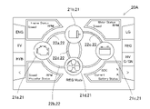
- FIG. 15 is a schematic view showing an aggregate screen 20A of a modified example.
- the operation mode includes "REG Mode".
- FIG. 15 is an aggregation screen 20A when "REG Mode” is selected.
- the "REG Mode” is a mode in which the power of the propulsion device (propeller) 101 is transmitted to the motor 103 to generate electricity and the battery 105 is charged (regenerative charging) when sailing using the sail of the ship.
- the motor output shaft 103a is rotated by the power of the propulsion machine 101, and the electric power generated by the motor 103 is charged to the battery 105. That is, the energy for charging the battery 105 flows from the propulsion machine 101 to the battery 105 via the motor 103. Therefore, in the aggregate screen 20A in the case of "REG Mode", the fourth linear portion 22d connecting the motor symbol 21b and the propulsion unit symbol 21d and the third linear portion connecting the motor symbol 21b and the battery symbol 21c. The color of 22c becomes blue. The color of the first linear portion 22a and the second linear portion 22b is white.
Landscapes
- Engineering & Computer Science (AREA)
- Combustion & Propulsion (AREA)
- Mechanical Engineering (AREA)
- Chemical & Material Sciences (AREA)
- General Engineering & Computer Science (AREA)
- Theoretical Computer Science (AREA)
- Ocean & Marine Engineering (AREA)
- Human Computer Interaction (AREA)
- Physics & Mathematics (AREA)
- General Physics & Mathematics (AREA)
- Remote Sensing (AREA)
- Radar, Positioning & Navigation (AREA)
- Transportation (AREA)
- Instrument Panels (AREA)
- Hybrid Electric Vehicles (AREA)
- Electric Propulsion And Braking For Vehicles (AREA)
Abstract
Description
図1は、本発明の実施形態に係る船舶用のハイブリッドシステム100の構成を示す概略図である。ハイブリッドシステム100は、船舶に備えられる。ハイブリッドシステム100は、船舶を推進する推進機101を駆動する。本実施形態では、推進機101はプロペラである。ハイブリッドシステム100は、エンジン102と、モータ103と、動力伝達装置104と、を備える。エンジン102とモータ103とは、推進機101を回転するための駆動源である。
(2-1.表示装置の概要)
図3は、本発明の実施形態に係る表示装置1の構成を示す正面図である。図3に示すように、表示装置1は、表示パネル1aと、表示パネル1aの外周を正面側から覆うベゼル1bと、を備える。表示パネル1aは、例えば、液晶パネルや有機ELパネルを用いて構成される。ベゼル1bは、正面からの平面視において枠状である。表示装置1の正面からの平面視において、ベゼル1bの内側が、画像が表示される画面領域10となる。
図4は、運転状態を集約して表示する集約画面20の構成を示す概略図である。本実施形態では、集約画面20は、船舶の乗員に対して重要情報を表示する画面であり、通常時において主として使われるメイン画面である。集約画面20は、上下方向に比べて左右方向が長い長方形状である。
表示装置1は、集約画面20に、現在時においてハイブリッドシステム100に発生している警告と異常とのうち少なくとも一方を知らせるアイコン60を表示可能に設けられることが好ましい。このように構成することにより、船舶の乗員は、ハイブリッドシステム100に発生した警告や異常を素早く認識することができる。なお、本実施形態では、アイコン60は、集約画面20のみならず、データリスト画面、警告リスト画面、および、異常リスト画面にも表示される。
運転モード表示部25は、現在時において選択可能な運転モードと、現在時において選択不能な運転モードとを、区別可能に表示する。このような構成によれば、船舶の乗員は、現在時に選択することができる運転モードを容易に認識することができる。
図15は、変形例の集約画面20Aを示す概略図である。変形例では、運転モードに『REG Mode』が含まれる。図15は、『REG Mode』が選択された場合の集約画面20Aである。『REG Mode』は、船舶の帆の利用した航走時に、推進機(プロペラ)101の動力をモータ103に伝達して発電を行い、バッテリ105の充電(回生充電)を行うモードである。
本明細書中に開示される種々の技術的特徴は、その技術的創作の主旨を逸脱しない範囲で種々の変更を加えることが可能である。また、本明細書中に示される複数の実施形態および変形例は可能な範囲で組み合わせて実施されてよい。
4・・・モード切替ボタン(ボタン)
20、20A・・・集約画面
21・・・記号
21a・・・エンジン記号
21b・・・モータ記号
21c・・・バッテリ記号
21d・・・推進機記号
22・・・線状部
22a・・・第1線状部
22b・・・第2線状部
22c・・・第3線状部
22d・・・第4線状部
24・・・状態表示部
24a・・・エンジン状態表示部
24b・・・モータ状態表示部
24c・・・バッテリ状態表示部
24d・・・推進機状態表示部
25・・・運転モード表示部
60・・・アイコン
60a・・・警告アイコン
60b・・・異常アイコン
100・・・ハイブリッドシステム
101・・・推進機
102・・・エンジン
103・・・モータ
105・・・バッテリ
Claims (10)
- 船舶を推進する推進機を駆動するハイブリッドシステムの運転状態を表示する表示装置であって、
前記運転状態を表示する表示画面には、
前記ハイブリッドシステムを構成する構成要素を表す記号と、
複数の前記記号間を繋ぎ、前記ハイブリッドシステムの運転モードに応じて点灯状態を変更する線状部と、
が含まれる、表示装置。 - 前記複数の記号には、エンジンを表す記号と、モータを表す記号と、バッテリを表す記号と、前記推進機を表す記号と、が含まれる、請求項1に記載の表示装置。
- 前記線状部の色は、
前記推進機を駆動するためのエネルギーの流れを示す第1エネルギーフローと、
前記バッテリを充電するためのエネルギーの流れを示す第2エネルギーフローと、
で異なる色とされる、請求項2に記載の表示装置。 - 前記表示画面には、前記記号に対応する前記ハイブリッドシステムの構成要素の状態を示す状態表示部が更に含まれる、請求項1から3のいずれか1項に記載の表示装置。
- 前記表示画面には、前記ハイブリッドシステムに設けられる複数種類の前記運転モードを表示する運転モード表示部が更に含まれる、請求項1から4のいずれか1項に記載の表示装置。
- 前記運転モード表示部は、現在時において選択可能な前記運転モードと、現在時において選択不能な前記運転モードとを、区別可能に表示する、請求項5に記載の表示装置。
- 前記運転モード表示部は、前記表示画面の端部に配置され、
前記表示画面の周囲には、前記運転モード表示部と並んで設けられ、各前記運転モードの選択を可能とする複数のボタンが配置される、請求項5又は6に記載の表示装置。 - 前記表示画面に、現在時において前記ハイブリッドシステムに発生している警告と異常とのうち少なくとも一方を知らせるアイコンを表示可能に設けられる、請求項1から7のいずれか1項に記載の表示装置。
- 前記表示画面とは異なる他の前記運転状態を示す画面に切替可能に設けられる、請求項1から8のいずれか1項に記載の表示装置。
- 請求項1から9のいずれか1項に記載の表示装置を備える、船舶。
Priority Applications (4)
| Application Number | Priority Date | Filing Date | Title |
|---|---|---|---|
| US18/039,380 US20240002024A1 (en) | 2020-11-27 | 2021-11-11 | Display device and ship |
| KR1020237016418A KR20230113288A (ko) | 2020-11-27 | 2021-11-11 | 표시 장치 및 선박 |
| EP21897728.8A EP4253160A4 (en) | 2020-11-27 | 2021-11-11 | Display device and ship |
| CN202180075608.9A CN116568563A (zh) | 2020-11-27 | 2021-11-11 | 显示装置及船舶 |
Applications Claiming Priority (2)
| Application Number | Priority Date | Filing Date | Title |
|---|---|---|---|
| JP2020197469A JP7684036B2 (ja) | 2020-11-27 | 2020-11-27 | 表示装置および船舶 |
| JP2020-197469 | 2020-11-27 |
Publications (1)
| Publication Number | Publication Date |
|---|---|
| WO2022113754A1 true WO2022113754A1 (ja) | 2022-06-02 |
Family
ID=81755864
Family Applications (1)
| Application Number | Title | Priority Date | Filing Date |
|---|---|---|---|
| PCT/JP2021/041562 Ceased WO2022113754A1 (ja) | 2020-11-27 | 2021-11-11 | 表示装置および船舶 |
Country Status (6)
| Country | Link |
|---|---|
| US (1) | US20240002024A1 (ja) |
| EP (1) | EP4253160A4 (ja) |
| JP (2) | JP7684036B2 (ja) |
| KR (1) | KR20230113288A (ja) |
| CN (1) | CN116568563A (ja) |
| WO (1) | WO2022113754A1 (ja) |
Families Citing this family (2)
| Publication number | Priority date | Publication date | Assignee | Title |
|---|---|---|---|---|
| USD1050169S1 (en) * | 2021-11-05 | 2024-11-05 | Thor Tech, Inc. | Display screen or portion thereof with a transitional graphical user interface |
| JP2025020881A (ja) | 2023-07-31 | 2025-02-13 | ヤンマーホールディングス株式会社 | 船舶 |
Citations (5)
| Publication number | Priority date | Publication date | Assignee | Title |
|---|---|---|---|---|
| JP3708925B2 (ja) | 2003-02-25 | 2005-10-19 | ヤンマー株式会社 | ハイブリッドシステム |
| US20100057281A1 (en) * | 2008-08-29 | 2010-03-04 | Paccar Inc | Information display systems and methods for hybrid vehicles |
| JP2010167960A (ja) * | 2009-01-23 | 2010-08-05 | Nissan Motor Co Ltd | ハイブリッド車の運転状態表示装置 |
| US8836544B1 (en) * | 2011-02-17 | 2014-09-16 | Brunswick Corporation | Multifunctional displays and display systems for marine vessels |
| KR20150031698A (ko) * | 2013-09-16 | 2015-03-25 | 엘에스엠트론 주식회사 | 하이브리드 트랙터용 디스플레이 장치와 이를 포함하는 하이브리드 트랙터용 인터페이스 시스템 |
Family Cites Families (3)
| Publication number | Priority date | Publication date | Assignee | Title |
|---|---|---|---|---|
| CN101118658A (zh) * | 2007-09-12 | 2008-02-06 | 吉林大学 | 混合动力客车用can总线仪表车控信息处理方法 |
| US8058982B2 (en) * | 2008-08-29 | 2011-11-15 | Paccar Inc | Information display systems and methods for hybrid vehicles |
| KR20130119771A (ko) * | 2012-04-24 | 2013-11-01 | 현대모비스 주식회사 | 하이브리드 차량에서 동력 흐름을 표시 방법 및 이를 표시하는 장치 |
-
2020
- 2020-11-27 JP JP2020197469A patent/JP7684036B2/ja active Active
-
2021
- 2021-11-11 CN CN202180075608.9A patent/CN116568563A/zh active Pending
- 2021-11-11 KR KR1020237016418A patent/KR20230113288A/ko active Pending
- 2021-11-11 WO PCT/JP2021/041562 patent/WO2022113754A1/ja not_active Ceased
- 2021-11-11 EP EP21897728.8A patent/EP4253160A4/en active Pending
- 2021-11-11 US US18/039,380 patent/US20240002024A1/en active Pending
-
2025
- 2025-01-20 JP JP2025007671A patent/JP2025061485A/ja active Pending
Patent Citations (5)
| Publication number | Priority date | Publication date | Assignee | Title |
|---|---|---|---|---|
| JP3708925B2 (ja) | 2003-02-25 | 2005-10-19 | ヤンマー株式会社 | ハイブリッドシステム |
| US20100057281A1 (en) * | 2008-08-29 | 2010-03-04 | Paccar Inc | Information display systems and methods for hybrid vehicles |
| JP2010167960A (ja) * | 2009-01-23 | 2010-08-05 | Nissan Motor Co Ltd | ハイブリッド車の運転状態表示装置 |
| US8836544B1 (en) * | 2011-02-17 | 2014-09-16 | Brunswick Corporation | Multifunctional displays and display systems for marine vessels |
| KR20150031698A (ko) * | 2013-09-16 | 2015-03-25 | 엘에스엠트론 주식회사 | 하이브리드 트랙터용 디스플레이 장치와 이를 포함하는 하이브리드 트랙터용 인터페이스 시스템 |
Non-Patent Citations (1)
| Title |
|---|
| See also references of EP4253160A4 |
Also Published As
| Publication number | Publication date |
|---|---|
| JP2025061485A (ja) | 2025-04-10 |
| JP2022085672A (ja) | 2022-06-08 |
| KR20230113288A (ko) | 2023-07-28 |
| EP4253160A1 (en) | 2023-10-04 |
| US20240002024A1 (en) | 2024-01-04 |
| JP7684036B2 (ja) | 2025-05-27 |
| CN116568563A (zh) | 2023-08-08 |
| EP4253160A4 (en) | 2024-12-11 |
Similar Documents
| Publication | Publication Date | Title |
|---|---|---|
| JP2025061485A (ja) | 表示装置および船舶 | |
| JP5850096B2 (ja) | 車両の情報表示装置 | |
| JP6068531B2 (ja) | ハイブリッド車両のsoc表示装置 | |
| JP5982716B2 (ja) | 船舶推進制御装置、船舶推進装置および船舶 | |
| JP6185945B2 (ja) | ハイブリッド車両のsoc表示装置 | |
| US10717361B2 (en) | Work vehicle and display device for the work vehicle | |
| JP2017077126A (ja) | 電動推進機およびバッテリユニット | |
| JP2011011611A (ja) | ハイブリッド車両の表示装置 | |
| JP2011220720A (ja) | 車両用入力システム | |
| JP6537464B2 (ja) | 作業車の表示装置 | |
| JP6745316B2 (ja) | 車両用情報表示装置 | |
| CN108944908A (zh) | 混合动力系统及其控制方法和车辆 | |
| CN117565956A (zh) | 方向盘组件和车辆 | |
| JP2016084014A (ja) | 作業車両 | |
| JP2012136848A (ja) | 作業機械の表示装置 | |
| US20250042388A1 (en) | Ship | |
| JP4055904B2 (ja) | ハイブリッド車両のアナログ表示装置 | |
| US20230398992A1 (en) | Hybrid vehicle system | |
| JP2007261581A (ja) | ハイブリッド車両のアナログ表示装置 | |
| US20250196636A1 (en) | Screen Transition Control System and Work Vehicle | |
| US20250289540A1 (en) | Display control method for maneuvering function display in marine vessel capable of executing various maneuvering functions and maneuvering system of marine vessel | |
| JP3690566B2 (ja) | インバータ用操作パネル | |
| CN116395018A (zh) | 一种车辆方向盘及车辆 | |
| WO2016063953A1 (ja) | 作業車両 | |
| JP2016084013A (ja) | 作業車両 |
Legal Events
| Date | Code | Title | Description |
|---|---|---|---|
| 121 | Ep: the epo has been informed by wipo that ep was designated in this application |
Ref document number: 21897728 Country of ref document: EP Kind code of ref document: A1 |
|
| WWE | Wipo information: entry into national phase |
Ref document number: 202180075608.9 Country of ref document: CN |
|
| WWE | Wipo information: entry into national phase |
Ref document number: 18039380 Country of ref document: US |
|
| NENP | Non-entry into the national phase |
Ref country code: DE |
|
| ENP | Entry into the national phase |
Ref document number: 2021897728 Country of ref document: EP Effective date: 20230627 |