WO2022113868A1 - 作業機 - Google Patents
作業機 Download PDFInfo
- Publication number
- WO2022113868A1 WO2022113868A1 PCT/JP2021/042394 JP2021042394W WO2022113868A1 WO 2022113868 A1 WO2022113868 A1 WO 2022113868A1 JP 2021042394 W JP2021042394 W JP 2021042394W WO 2022113868 A1 WO2022113868 A1 WO 2022113868A1
- Authority
- WO
- WIPO (PCT)
- Prior art keywords
- lock
- axis
- lever
- support shaft
- operating
- Prior art date
- Legal status (The legal status is an assumption and is not a legal conclusion. Google has not performed a legal analysis and makes no representation as to the accuracy of the status listed.)
- Ceased
Links
Images


Classifications
-
- E—FIXED CONSTRUCTIONS
- E02—HYDRAULIC ENGINEERING; FOUNDATIONS; SOIL SHIFTING
- E02F—DREDGING; SOIL-SHIFTING
- E02F9/00—Component parts of dredgers or soil-shifting machines, not restricted to one of the kinds covered by groups E02F3/00 - E02F7/00
- E02F9/20—Drives; Control devices
- E02F9/2004—Control mechanisms, e.g. control levers
- E02F9/2012—Setting the functions of the control levers, e.g. changing assigned functions among operations levers, setting functions dependent on the operator or seat orientation
-
- E—FIXED CONSTRUCTIONS
- E02—HYDRAULIC ENGINEERING; FOUNDATIONS; SOIL SHIFTING
- E02F—DREDGING; SOIL-SHIFTING
- E02F3/00—Dredgers; Soil-shifting machines
- E02F3/04—Dredgers; Soil-shifting machines mechanically-driven
- E02F3/28—Dredgers; Soil-shifting machines mechanically-driven with digging tools mounted on a dipper- or bucket-arm, i.e. there is either one arm or a pair of arms, e.g. dippers, buckets
- E02F3/30—Dredgers; Soil-shifting machines mechanically-driven with digging tools mounted on a dipper- or bucket-arm, i.e. there is either one arm or a pair of arms, e.g. dippers, buckets with a dipper-arm pivoted on a cantilever beam, i.e. boom
- E02F3/32—Dredgers; Soil-shifting machines mechanically-driven with digging tools mounted on a dipper- or bucket-arm, i.e. there is either one arm or a pair of arms, e.g. dippers, buckets with a dipper-arm pivoted on a cantilever beam, i.e. boom working downwardly and towards the machine, e.g. with backhoes
- E02F3/325—Backhoes of the miniature type
-
- E—FIXED CONSTRUCTIONS
- E02—HYDRAULIC ENGINEERING; FOUNDATIONS; SOIL SHIFTING
- E02F—DREDGING; SOIL-SHIFTING
- E02F9/00—Component parts of dredgers or soil-shifting machines, not restricted to one of the kinds covered by groups E02F3/00 - E02F7/00
- E02F9/20—Drives; Control devices
- E02F9/2004—Control mechanisms, e.g. control levers
-
- G—PHYSICS
- G05—CONTROLLING; REGULATING
- G05G—CONTROL DEVICES OR SYSTEMS INSOFAR AS CHARACTERISED BY MECHANICAL FEATURES ONLY
- G05G5/00—Means for preventing, limiting or returning the movements of parts of a control mechanism, e.g. locking controlling member
- G05G5/005—Means for preventing, limiting or returning the movements of parts of a control mechanism, e.g. locking controlling member for preventing unintentional use of a control mechanism
-
- G—PHYSICS
- G05—CONTROLLING; REGULATING
- G05G—CONTROL DEVICES OR SYSTEMS INSOFAR AS CHARACTERISED BY MECHANICAL FEATURES ONLY
- G05G1/00—Controlling members, e.g. knobs or handles; Assemblies or arrangements thereof; Indicating position of controlling members
- G05G1/01—Arrangements of two or more controlling members with respect to one another
-
- G—PHYSICS
- G05—CONTROLLING; REGULATING
- G05G—CONTROL DEVICES OR SYSTEMS INSOFAR AS CHARACTERISED BY MECHANICAL FEATURES ONLY
- G05G1/00—Controlling members, e.g. knobs or handles; Assemblies or arrangements thereof; Indicating position of controlling members
- G05G1/04—Controlling members for hand actuation by pivoting movement, e.g. levers
-
- G—PHYSICS
- G05—CONTROLLING; REGULATING
- G05G—CONTROL DEVICES OR SYSTEMS INSOFAR AS CHARACTERISED BY MECHANICAL FEATURES ONLY
- G05G2505/00—Means for preventing, limiting or returning the movements of parts of a control mechanism, e.g. locking controlling member
Definitions
- the present invention relates to a working machine such as a backhoe.
- a working machine equipped with a lock mechanism for locking or unlocking (unlocking) the movement of an operating member is known.
- a cockpit is provided in front of the driver's seat on the machine body.
- the control table is provided with an operating member for operating the traveling device, an operating support shaft for supporting the operating member, a lock mechanism, and a lock lever for operating the lock mechanism.
- the lock mechanism has an engaging portion that rotates integrally with the operating member, and an engaged portion that restrains the movement of the operating member by engaging with the engaging portion and allows the movement of the operating member by disengaging from the engaging portion. It is composed of a lock body having a portion (lock pin), a lock support shaft that supports the lock body, and an interlocking mechanism that interlocks the lock lever and the lock body.
- Patent Document 2 the working machine disclosed in Patent Document 2 is known.
- a plurality of fuel devices such as a fuel prefilter, a fuel pump, and a fuel main filter connected to a pipe through which fuel flows are attached to a mounting member (bracket).
- the mounting member is bolted to the side surface of the hydraulic oil tank.
- Japanese Patent Publication Japanese Patent Laid-Open No. 2018-199917
- Japanese Patent Gazette No. 5704304
- an object of the present invention is to provide a working machine capable of improving the operation accuracy of a lock mechanism that locks or unlocks the movement of an operating member.
- Another object of the present invention is to provide a working machine capable of improving the operation accuracy of a lock mechanism that locks or unlocks the movement of an operating member.
- the working machine includes a machine body, a driver's seat provided on the machine body, and a cockpit provided in front of the driver's seat, and the cockpit is an operation of extending in the width direction of the machine body.
- a work machine having a lock mechanism that can be switched to, and the lock mechanism is a lock body having an engaging portion that rotates integrally with an operating member and an engaged portion that engages with the engaging portion.
- a lock support shaft that rotatably supports one end of the lock body and a drive portion that applies a driving force to the other end of the lock body are included, and the engaged portion includes one end and the other end of the lock body.
- the lock body is provided in the intermediate portion between the portions, and the lock body rotates around the lock support shaft when a driving force is applied by the driving portion to engage the engaged portion with the engaging portion. And the position is changed to the disengagement position where the engaged part is disengaged from the engaging part.
- the drive unit has an interlocking portion provided on the operation support shaft and rotating integrally with the operation support shaft, and a connecting member for connecting the interlocking portion and the lock body, and the lock body is the lock body.
- the other end is rotatably connected to the connecting member relative to the connecting member.
- the lock support shaft is arranged on either the front side or the rear side of the aircraft with respect to the operation support shaft, and the interlocking portion is located on the other side of the front side or the rear side of the aircraft with respect to the operation support shaft. Arranged, the lock body and the connecting member are connected above or below the operating support shaft.
- the engaging portion has an engaging groove that protrudes radially outward from the base of the operating member and is recessed from the tip of the engaging portion toward the operating support shaft, and the interlocking portion has an interlocking portion.
- the connecting member is arranged above the operation support shaft, and the lock support shaft is below the operation support shaft and abbreviated as the operation support shaft.
- the lock body swings in the front-rear direction around the axis of the lock support shaft, and the engaged portion projects from the intermediate portion of the lock body in the width direction of the machine body. It consists of a lock pin that engages or disengages from the engaging groove.
- the cockpit can be repositioned to a first position that allows the driver to get on and off via a passage provided between the driver's seat and the cockpit, and a second position that prevents the driver from getting on and off.
- the drive unit has a lock lever, and the drive unit transmits an operating force for changing the position of the lock lever as the drive force to the other end of the lock body, and transfers the lock body to the lock support shaft. Rotate around the axis.
- the drive unit has an actuator that generates the drive force.
- the work machine includes a work device supported in front of the machine body and a traveling device that supports the machine body so as to be able to travel, and the control table is a plurality of operating devices for operating the work device and the traveling device, respectively.
- the operating member constitutes a traveling lever that operates the traveling device.
- the working machine includes a machine body and a control table provided on the machine body, and the control table includes a first axis extending in the width direction of the machine body and the first axis.
- a first operating member supported around the axis so as to be relatively rotatable with respect to the first axis, a locked state that restrains the movement of the first operating member, and an unlocked state that allows the movement of the first operating member.
- a lock mechanism that can be switched to, a second axis provided parallel to the first axis, and a second operation supported so as to be rotatable relative to the second axis around the axis of the second axis.
- the lock mechanism has a member, and the lock mechanism is driven by an engaging portion that rotates integrally with the first operating member, a lock body having an engaged portion that engages with the engaging portion, and a lock body.
- the second axis includes a drive unit that applies a force, the second axis supports the lock body so as to be relatively rotatable with respect to the second axis, and the lock body is provided with a drive force by the drive unit.
- the control table has a plurality of third operation members capable of operating a plurality of operation targets, and an operation switching mechanism for switching each operation target of the plurality of third operation members.
- a third axis provided between the first axis and the second axis in parallel with the first axis, and rotatably supported around the axis of the third axis with respect to the third axis.
- the lock body includes a plurality of rotating members, and a plurality of link members selectively rotatably connected to any one of the plurality of third operating members and the plurality of rotating members. Is arranged over the first axis from the second axis via the radial outside of any of the plurality of rotating members.
- the drive unit has an interlocking portion provided on the first shaft and rotatable integrally with the first shaft, and a connecting member rotatably connected to the interlocking portion and the lock body.
- the connecting portion between the interlocking portion and the connecting member is arranged at a position away from the second axis of the engaged portion of the lock body, and the connecting portion between the lock body and the connecting member is described above. It is arranged at a position closer to the second axis than the engaged portion of the lock body.
- the engaging portion has an engaging groove that protrudes radially outward from the base of the first operating member and is recessed from the tip of the engaging portion toward the first shaft, and is interlocked with the engaging portion.
- the portion protrudes radially outward and upward of the first axis
- the connecting member is arranged from above the first axis to below via the radial outside
- the second axis is the first axis.
- the lock body swings in the front-rear direction around the axis of the second axis, and the engaged portion projects from the upper end portion of the lock body in the width direction of the machine body. It is composed of a lock pin that engages with or disengages from the engaging groove.
- the control table has an arm protrusion protruding outward in the radial direction of the first axis from a position different from the engagement portion at the base of the first operation member, and a joint rotatably connected to the arm protrusion.
- a rod whose one end is connected to the spool of the control valve, a first screwed portion screwed into the first screwed portion provided on the joint, and a second portion provided at the other end of the rod. It has a relay member including a second screwed portion screwed into the two screwed portions, and has a screwed structure of the first screwed portion and the first screwed portion, and the second screwed portion.
- the screw structure of the joint portion and the second screwed portion one screw structure is formed in a right-handed screw shape, and the other screw structure is formed in a left-hand screw shape.
- the lock body has a groove portion into which any of the plurality of rotating members enters without contacting the lock body when it is in the engaging position.
- the control table has a lock lever whose position can be changed between a first position and a second position by swinging operation, and the drive unit uses the operating force of the lock lever as the driving force to the lock body. It is transmitted to change the position between the engaging position and the disengaging position.
- the drive unit has an actuator that generates the drive force.
- the working machine includes a traveling device that supports the machine so as to be able to travel, a working device supported by the machine, and a dozer device, and the control table is the traveling device, the working device, and the dozer device.
- the traveling lever that operates the traveling device constitutes the first operating member
- the dozer lever that operates the dozer device constitutes the second operating member.
- the control lever that is configured and operates the working device constitutes the third operating member.
- the working device includes a boom rotatably connected to the machine body and an arm rotatably connected to the tip of the boom, and the third operating member operates the boom and the arm, respectively.
- the operation switching mechanism includes a plurality of control levers, and each of the plurality of control levers can be switched between a boom operation lever for operating the boom and an arm operation lever for operating the arm.
- the working machine includes a machine body, a tank provided in the machine body and for storing liquid, a lid body detachably attached to the tank and closing the opening of the tank, and a plurality of devices.
- the mounting member is integrated with the lid body.
- the lid has four or more through holes formed at predetermined intervals along the peripheral end portion of the lid, and is fixed to the tank by a fastening member inserted into each of the through holes. Has been done.
- a working device supported by the machine body is provided, and the tank is a hydraulic oil tank for storing hydraulic oil for operating the working device, or a fuel tank for storing fuel.
- the plurality of devices include devices provided in different piping systems or wiring systems.
- the working machine includes an electric circuit through which an electric current flows and a flow path through which a fluid flows, and the plurality of devices include a first device provided in the electric circuit and a second device provided in the flow path. And, and the first device and the second device are attached to the mounting member.
- the working machine includes a prime mover including an engine mounted on the machine body, the flow path includes a fuel flow path for supplying fuel to the prime mover, and the second device includes the fuel flow path in the fuel flow path.
- a provided fuel device is included, and the first device includes an electric device through which a current flows through the electric circuit, and the fuel device and the electric device are attached to the mounting member.
- At least one of the fuel pump and the fuel filter included in the fuel device is attached to the mounting member.
- the electrical device includes an isolator that cuts off the current flowing through the electric circuit and a fuse box containing a fuse that prevents an overcurrent from flowing through the electric circuit, at least one of which is attached to the mounting member. Has been done.
- the flow path includes the cooling liquid flow path through which the cooling liquid flows, the cooling device provided in the cooling liquid flow path includes a reserve tank for storing the cooling liquid, and the mounting member includes the cooling liquid.
- the reserve tank is constrained in at least one direction.
- the plurality of devices include electric devices provided in an electric path through which an electric current flows, fuel devices provided in a fuel flow path through which fuel flows, hydraulic devices provided in a hydraulic oil flow path through which hydraulic oil flows, and coolant.
- the cooling devices provided in the flowing coolant flow path two or more types of devices are included.
- the mounting member has a plurality of support portions that support the plurality of devices and restrain them in at least one direction, and the support portions include hoses for hoses provided in the flow path and connected to the devices.
- a support is included.
- 3 is a plan view of the vicinity of the hydraulic oil tank of the third embodiment. It is a rear view of the vicinity of the hydraulic oil tank of the 3rd embodiment. It is the figure which looked at the vicinity of the attachment member of 3rd Embodiment from the front. It is a figure which looked at the vicinity of the attachment member of another example of 3rd Embodiment from the front. It is a front view of the mounting member of the 3rd Embodiment. It is a top view of the mounting member of 3rd Embodiment. It is a rear view of the mounting member of the 3rd embodiment. It is a side view of a working machine. It is a front view of a working machine. It is a side view of the upper part of a working machine. It is a top view of the upper part of a working machine.
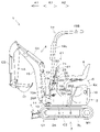
- FIG. 24 is a schematic side view showing the overall configuration of the working machine 1.
- FIG. 25 is a schematic front view of the working machine 1.
- FIG. 26 is a schematic side view of the upper part of the working machine 1.
- FIG. 27 is a schematic plan view of the upper part of the working machine 1.
- a backhoe which is a turning work machine, is exemplified as the work machine 1.
- the working machine 1 includes a machine body (swivel table) 2, a traveling device 3, a working device 4, and the like.
- a driver's seat 6 on which the driver (operator) D (see FIGS. 26 and 27) is seated is mounted on the machine body 2.
- the front side of the driver D seated in the driver's seat 6 of the work machine 1 (direction of arrow A1 in FIGS. 24 and 26) is forward, and the rear side of the driver D (arrow A2 in FIGS. 24 and 26) is forward.
- the direction) will be described as the rear, the left side of the driver D (direction of arrow B1 in FIGS. 25 and 27) as the left side, and the right side of the driver D (direction of arrow B2 in FIGS. 25 and 27) as the right side.
- the horizontal direction which is the direction orthogonal to the front-rear direction K1
- the machine width direction horizontal width direction of the machine 2
- the airframe width direction K2 which is the direction away from the center of the airframe 2 to the left or right side.
- the direction opposite to the outside of the aircraft will be described as the inside of the aircraft.
- the inside of the machine is the width direction K2 of the machine, which is the direction from the left or right of the body 2 toward the center.
- the traveling device 3 is a device that supports the machine body 2 so as to be able to travel.
- the traveling device 3 has a traveling frame 3A, a first traveling device 3L provided on the left side of the traveling frame 3A, and a second traveling device 3R (FIG. 25) provided on the right side of the traveling frame 3A.
- the first traveling device 3L and the second traveling device 3R are crawler type traveling devices.
- the first traveling device 3L is driven by the first traveling motor (traveling motor) M1.
- the second traveling device 3R is driven by the second traveling motor (traveling motor) M2.
- the first traveling motor M1 and the second traveling motor M2 are composed of a hydraulic motor (hydraulic actuator).
- a dozer device 7 is attached to the front portion of the traveling device 3.
- the dozer device 7 can be raised and lowered (blades are raised and lowered) by expanding and contracting the dozer cylinder C1 (hydraulic actuator).
- the machine body 2 is supported on the traveling frame 3A so as to be able to swivel around the vertical axis (axis center extending in the vertical direction) via the swivel bearing 8.
- the machine body 2 is driven in the turning direction by a turning motor M3 which is a hydraulic motor (hydraulic actuator).
- the machine body 2 has a substrate (hereinafter referred to as a swivel substrate) 9 that swivels around the vertical axis and a weight 10.
- the swivel substrate 9 is made of a steel plate or the like and is connected to the swivel bearing 8.
- the weight 10 is provided at the rear of the machine body 2.
- the motor Eg is mounted on the rear part of the aircraft 2.
- the prime mover Eg is a diesel engine.
- the prime mover Eg may be a gasoline engine, an LPG engine, an electric motor, or the like, or may be a hybrid type prime mover having an engine and an electric motor.
- the prime mover Eg is covered by the bonnet 5.
- a driver's seat 6 is provided on the bonnet 5.
- the center of the driver's seat 6 in the body width direction K2 and the center of the bonnet 5 in the body width direction K2 substantially coincide with each other. Further, both sides (left side and right side) of the bonnet 5 in the body width direction K2 protrude from the driver's seat 6 to the outside of the machine body.
- a support bracket 13 is provided on the front part of the machine body 2.
- the support bracket 13 is installed slightly to the right of the center of K2 in the width direction of the machine body.
- a swing bracket 14 is swingably attached to the support bracket 13 around the vertical axis.
- a working device 4 is attached to the swing bracket 14. That is, the working device 4 is supported by the front portion of the machine body 2.
- the working device 4 is also shown in FIG. 25, for convenience, the positions of each part of the working device 4 in the height direction are different between FIGS. 25 and 24.
- the working device 4 has a boom 15, an arm 16, and a bucket (working tool) 17.
- the base of the boom 15 is pivotally attached to the swing bracket 14 around a horizontal axis (an axis extending in the width direction of the machine body K2) so as to be rotatable.
- the boom 15 can swing up and down.
- the arm 16 is pivotally attached to the tip end side of the boom 15 so as to be rotatable around a horizontal axis.
- the arm 16 can swing back and forth or up and down.
- the bucket 17 is provided on the tip end side of the arm 16 so that it can be squeezed and dumped.
- the work machine 1 can be equipped with another work tool (hydraulic attachment) that can be driven by a hydraulic actuator in place of or in addition to the bucket 17.
- a hydraulic actuator in place of or in addition to the bucket 17.
- other working tools include hydraulic breakers, hydraulic crushers, angle blooms, earth augers, pallet forks, sweepers, mowers, snow blowers and the like.
- the swing bracket 14 can be swung by the expansion and contraction of the swing cylinder C2 provided in the machine body 2.
- the boom 15 can be swung by the expansion and contraction of the boom cylinder C3.
- the arm 16 can be swung by the expansion and contraction of the arm cylinder C4.
- the bucket 17 can be squeezed and dumped by expanding and contracting the bucket cylinder (working tool cylinder) C5.
- the dozer cylinder C1, the swing cylinder C2, the boom cylinder C3, the arm cylinder C4, and the bucket cylinder C5 are composed of hydraulic cylinders (hydraulic actuators). Further, the boom cylinder C3, the arm cylinder C4, and the bucket cylinder C5 are hydraulic actuators for work that drive the work device 4.
- the work machine 1 is provided with a control device 21 for manipulating the work machine 1.
- the control device 21 has a control table 23.
- the cockpit 23 is provided on the machine body 2 at the rear A2 of the work device 4 and at the front A1 of the driver's seat 6 and the bonnet 5.
- a passage 22 is provided between the cockpit 23 and the driver's seat 6 and the bonnet 5.
- the passages 22 are formed at predetermined intervals on the floor portion 24 between the cockpit 23 and the bonnet 5. Further, the passage 22 is open to the left and right of the machine body 2 and can pass through (walk through) in the body width direction K2. Therefore, the driver D can get on and off the work machine 1 from either the left or right side of the work machine 1 via the passage 22, and can sit on and off the driver's seat 6. Seats are possible.
- the cockpit 23 has a cover 26.
- the cover 26 has a first cover 26F provided on the work device 4 side (front A1 side) and a second cover 26B provided on the driver's seat 6 side (rear A2 side).
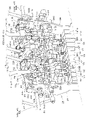
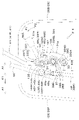
- FIG. 1 is a perspective view of the upper part of the cockpit 23 as viewed from the rear A2 (driver's seat 6 side in FIGS. 24 to 27).
- FIG. 2 is a rear view of the internal structure of the cockpit 23 (viewed from the driver's seat 6 side in FIGS. 24 to 27).
- FIG. 1 shows both the first cover 26F and the second cover 26B, but FIG. 2 shows a state in which the second cover 26B is removed.
- the first cover 26F and the second cover 26B are combined in the front-rear direction K1 to form the housing of the cockpit 23.
- the cover 26 covers the internal structure of the cockpit 23 as shown in FIG. 2 and the like.
- the internal structure of the cockpit 23 includes a support frame 25 which is a skeleton of the cockpit 23.
- the first cover 26F and the second cover 26B are fixed to the support frame 25 by fastening members (not shown) such as bolts and nuts.
- a plurality of windows 26c and 26d are provided on the rear surface 26a of the second cover 26B of the cockpit 23.
- Each of the windows 26c and 26d is a through hole having a predetermined size.
- the windows 26c and 26d are provided with lids 26g and 26h that can be opened and closed by a hinge structure.
- FIG. 1 shows a state in which the lid 26g is opened and the window 26c is opened, and a state in which the lid 26h is closed and the window 26d is closed.
- the rear surface 26a of the second cover 26B is provided with electrical components 18s such as various warning lamps.
- a protective member (rops) 19 is attached to the cockpit 23.
- the protective member 19 protects the driver D seated in the driver's seat 6.
- the protective member 19 has a mounting portion 19A, a vertical portion 19L, 19R, a horizontal portion 19B, 19C, and a connecting portion 19D, 19E.
- the protective member 19 is not shown for convenience.
- the mounting portion 19A is arranged over the front A1 of the first cover 26F and the left and right sides.
- a support plate 20L is interposed between the left side portion 19g of the mounting portion 19A and the left side wall 26L of the first cover 26F.
- a support plate 20R is interposed between the right side portion 19h of the mounting portion 19A and the right side wall 26R of the first cover 26F.
- the support plates 20L and 20R are erected on the machine body 2.
- the left side portion 19g of the mounting portion 19A is fixed to the support plate 20L and the first vertical member 27 (FIG. 2) of the support frame 25 by the fastening member 200.
- the right side portion 19h of the mounting portion 19A is fixed to the support plate 20R and the second vertical member 28 (see FIG. 2) of the support frame 25 by the fastening member 200.
- Each fastening member 200 penetrates both side walls 26L and 26R of the first cover 26F.
- the side walls 26L and 26R of the first cover 26F may or may not be fixed to both side portions 19g and 19h of the mounting portion 19A and the support plates 20L and 20R.
- the vertical portions 19L and 19R extend upward from both side portions 19g and 19h of the mounting portion 19A, respectively.
- Lateral portions 19B and 19C extend from the upper ends of the vertical portions 19L and 19R toward the rear A2, respectively.
- the rear ends of the lateral portions 19B and 19C are connected to each other by the connecting portion 19D extending in the body width direction K2.
- the vertical portions 19L and 19R are connected to each other by a connecting portion 19E extending in the machine width direction K2.
- the mounting portion 19A is arranged in the front A1 of the first cover 26F, but is not arranged in the rear A2 of the second cover 26B. Therefore, as shown in FIGS. 24 and 25, the second cover 26B can be removed with the protective member 19 attached, but the first cover 26A cannot be removed.
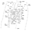
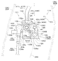
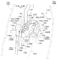
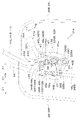
- FIG. 3 is a perspective view of the upper part of the internal structure of the cockpit 23 as viewed from the rear (driver's seat 6 side).
- FIG. 4 is a front view of the upper part of the internal structure of the cockpit 23.
- FIG. 5 is a perspective view of the upper part of the internal structure of the cockpit 23 as viewed from the front side of the machine body 2 (working device 4 side).
- FIG. 6 is a perspective view of the upper part of the support frame 25 as viewed from the rear.
- the support frame 25 of the cockpit 23 includes a first vertical member 27 constituting the left portion, a second vertical member 28 constituting the right portion, and both vertical members 27, 28. It has a connecting body 29 and a connecting body 29 for connecting the above.
- the first vertical member 27 and the second vertical member 28 are formed in a plate shape.
- the first vertical member 27 and the second vertical member 28 are erected on the machine body 2 with their respective plate surfaces facing the machine body width direction K2. Further, the first vertical member 27 and the second vertical member 28 face each other with a predetermined interval in the machine width direction K2.
- the connecting body 29 is provided between the upper portions of the first vertical member 27 and the second vertical member 28.
- the connecting body 29 has a first connecting material 30, a second connecting material 31, and a third connecting material 32.
- the first connecting member 30 is connected to the upper part of the first vertical member 27.
- the second connecting member 31 is connected to the upper part of the second vertical member 28.
- the first connecting member 30 and the second connecting member 31 are provided at intervals in the machine width direction K2.
- the third connecting material 32 connects the first connecting material 30 and the second connecting material 31.
- the first connecting member 30 is arranged on the side of the second vertical member 28 with respect to the first vertical member 27 and is connected to the first vertical member 27.
- the first connecting member 30 has a first wall 30a and a second wall 30b.
- the first wall 30a is fixed along the first vertical member 27.
- a first bearing cylinder 69L is arranged below the first wall 30a.
- the first bearing cylinder 69L is provided through the first vertical member 27 in a penetrating manner, and has an axial center extending in the machine width direction K2.
- the second wall 30b extends from the front end of the first wall 30a toward the inside of the aircraft.
- a first support cylinder 68L is provided on the second wall 30b in a penetrating manner.
- the first support cylinder 68L has an axial center extending in the front-rear direction K1.
- the second connecting member 31 is arranged on the side of the first vertical member 27 with respect to the second vertical member 28 and is connected to the second vertical member 28.
- the second connecting member 31 has a first wall 31a and a second wall 31b.
- the first wall 31a is fixed along the second vertical member 28.
- a second bearing cylinder 69R is arranged below the first wall 31a.
- the second bearing cylinder 69R is provided in a penetrating shape on the second vertical member 28, and has an axial center extending in the machine width direction K2.
- the second wall 31b extends from the front end of the first wall 31a toward the inside of the aircraft.
- a second support cylinder 68R is provided on the second wall 31b in a penetrating manner.
- the second support cylinder 68R has an axial center extending in the front-rear direction K1.
- the third connecting member 32 has a first wall portion 32a, a second wall portion 32b, and a lower base portion 32c behind the first connecting member 30 and the second connecting member 31 (on the driver's seat 6 side). And have.
- the first wall portion 32a is fixed so as to project rearward from the rear surface of the right end portion of the second wall 30b of the first connecting member 30.
- the second wall portion 32b is fixed so as to project rearward from the rear surface of the left end portion of the second wall 31b of the second connecting member 31.
- the first wall portion 32a and the second wall portion 32b project downward from the first connecting member 30 and the second connecting member 31.
- the lower base portion 32c connects the lower end portion of the first wall portion 32a and the lower end portion of the second wall portion 32b.
- the lower base portion 32c has a plate shape, and each plate surface thereof faces upward or downward.
- the third connecting member 32 is in front of the first connecting member 30 and the second connecting member 31 (on the working device 4 side), the third wall portion 32d, the fourth wall portion 32e, and the front. It has a base 32f.
- the third wall portion 32d is fixed so as to project forward from the front surface of the second wall 30b of the first connecting member 30.
- the fourth wall portion 32e is fixed so as to project forward from the front surface of the second wall 31b of the second connecting member 31.
- the front base portion 32f connects the front end portion of the third wall portion 32d and the front end portion of the fourth wall portion 32e.
- the front base portion 32f has a plate shape, and each plate surface thereof faces forward or backward. In FIG. 5, for convenience, the third wall portion 32d, the fourth wall portion 32e, and the front base portion 32f are not shown.
- the first wall portion 32a, the second wall portion 32b, and the lower base portion 32c of the third connecting member 32 are separated from the third wall portion 32d, the fourth wall portion 32e, and the front base portion 32f.
- the wall portions 32a, 32b, 32d, 32e, 32f of the third connecting member 32 and the base portions 32c, 32f may be integrated.
- An operation support shaft 34 is provided on the upper part of the support frame 25.
- the operation support shaft 34 has an axial center extending in the machine width direction K2.
- the operation support shaft 34 is rotatably supported by the support frame 25 around its axis. Further, the operation support shaft 34 is located above the lower base portion 32c of the third connecting member 32.
- Base plates 53L and 53R are connected to both ends of the operation support shaft 34, respectively. As shown in FIG. 24, the base plate 53L on the left side is arranged on the second cover 26B side from the root portion 19t of the vertical portion 19L connected to the mounting portion 19A of the protective member 19. Similarly, the base plate 53R on the right side is arranged on the second cover 26B side from the root portion 19t of the vertical portion 19R (not shown). Therefore, the operation support shaft 34 is also arranged on the second cover 26B side from the root portion 19t of the vertical portions 19L and 19R.
- the operation support shaft 34 has a first shaft 34A and a second shaft 34B.
- the first shaft 34A is inserted through the first bearing cylinder 69L, and the first walls 30a and 31a of the first and second connecting members 30 and 31 and the first wall portion 32a and the second wall portion 32b of the third connecting member 32 are inserted. And penetrates.
- the first shaft 34A is rotatably supported around the axis of the first bearing cylinder 69L by the first bearing cylinder 69L and the first wall portion 32a and the second wall portion 32b of the third connecting member 32.
- the second axis 34B is concentrically arranged on the right side of the first axis 34A.
- the second shaft 34B has a second bearing cylinder 69R inserted therein.
- the second shaft 34B is supported by the second bearing cylinder 69R so as to be rotatable around the axis of the second bearing cylinder 69R.
- the first axis 34A and the second axis 34B are arranged at intervals in the body width direction K2. As shown in FIG. 6 and the like, a connecting member 11 is provided between the first shaft 34A and the second shaft 34B.
- the first shaft 34A and the second shaft 34B are integrally rotatably connected by a connecting member 11.
- the operation support shaft 34 including the first shaft 34A and the second shaft 34B includes the first vertical member 27, the second vertical member 28, the first connecting member 30, the second connecting member 31, and the third. It is supported by the first wall portion 32a of the connecting member 32.
- the operation support shaft 34 may be composed of one shaft.
- the connecting member 11 is a connecting wall 11C that connects the first side wall 11A connected to the first shaft 34A, the second side wall 11B connected to the second shaft 34B, and the first side wall 11A and the second side wall 11B. And an extension portion 11D extending upward from the second side wall 11B.
- the first side wall 11A and the second side wall 11B are arranged at predetermined intervals in the body width direction K2.
- the connecting wall 11C connects the rear ends of the first side wall 11A and the second side wall 11B to each other.
- connection cylinder 64 is provided on the first side wall 11A.
- the right end portion of the first shaft 34A is inserted into the connection cylinder 64 and fixed to the connection cylinder 64.
- the first shaft 34A and the first side wall 11A can be integrally rotated.
- the second shaft 34B is fixed to the second side wall 11B by welding or the like.
- the extending portion 11D is provided with a plate 11E and a first spring hooking portion 70.
- the first spring hooking portion 70 is composed of a pin and projects from the extending portion 11D toward the first shaft 34A.
- a second spring hooking portion 72 is provided below the second wall 31b of the second connecting member 31.
- the second spring hooking portion 72 is composed of a bending pin and is fixed to the holding plate 100.
- the holding plate 100 is fixed to the plate surface of the second vertical member 28 on the side of the machine body, and protrudes forward from the second vertical member 28.
- the second spring hooking portion 72 protrudes from the holding plate 100 toward the first shaft 34A and bends forward.
- a tubular body 39L is provided on the left portion (between the first wall portion 30a of the first connecting member 30 and the first wall portion 32a of the third connecting member 32) on the first shaft 34A. It is fitted.
- the tubular body 39L is fixed to the first shaft 34A by a pin or the like, and can rotate integrally with the first shaft 34A.
- a cylindrical spacer 39R is fitted in the right portion (between the second wall portion 32b of the third connecting member 32 and the connecting member 11) on the first shaft 34A.
- the spacer 39R is fixed to the first shaft 34A by a pin or the like.
- control valve 35 is provided on the control table 23.
- the control valve 35 is an aggregate of a plurality of control valves V1 to V10 for controlling the hydraulic actuator provided in the working machine 1, and is provided between the lower portions of the first vertical member 27 and the second vertical member 28.
- Each control valve V1 to V10 is a direct acting spool type direction switching valve.
- the spools of the control valves V1 to V10 are held in the neutral position by the urging force of the urging spring housed in the valve body, and are operated up and down from the neutral position against the urging force of the urging spring.
- the plurality of control valves are the first control valve V1 to the tenth control valve V10.
- the first control valve V1 to the tenth control valve V10 are mechanically operated direction switching valves whose spools can be manually switched.
- the first control valve V1 is a speed change control valve that controls a swash plate angle cylinder (not shown) that changes the tilt angle of the swash plate of the first traveling motor M1 and the second traveling motor M2 (FIG. 25).
- the second control valve V2 is a swivel control valve that controls the swivel motor M3 (FIG. 24).
- the third control valve V3 is an arm control valve that controls the arm cylinder C4 (FIG. 24).
- the fourth control valve V4 is a first traveling control valve (traveling control valve) that controls the first traveling motor M1 (FIG. 24).
- the fifth control valve V5 is a control valve for a dozer that controls the dozer cylinder C1 (FIG. 24).
- the sixth control valve V6 is a spare control valve that controls the hydraulic attachment.
- the seventh control valve V7 is a second traveling control valve (traveling control valve) that controls the second traveling motor M2.
- the eighth control valve V8 is a swing control valve that controls the swing cylinder C2 (FIG. 24).
- the ninth control valve V9 is a bucket control valve that controls the bucket cylinder C5 (FIG. 24).
- the tenth control valve V10 is a boom control valve that controls the boom cylinder C3 (FIG. 24).
- the third control valve V3, the ninth control valve V9, and the tenth control valve V10 are work control valves that control the hydraulic actuator that drives the work device 4 (FIG. 24).
- the control table 23 is provided with an operation shaft 33.
- the operating shaft 33 is provided below the connecting body 29 and the operating support shaft 34 and above the control valve 35.
- the operation shaft 33 has an axial center extending in the machine width direction K2, and is provided over the first vertical member 27 and the second vertical member 28. Further, the operation shaft 33 is rotatably supported around the axis center by the first vertical member 27 and the second vertical member 28. The right portion of the operation shaft 33 projects outward from the second vertical member 28.
- the first rotating cylinder 38A to the fifth rotating cylinder 38E are fitted on the operation shaft 33.
- the third rotating cylinder 38C rotates integrally with the operating shaft 33, and the other rotating cylinders 38A, 38B, 38D, and 38E rotate relative to the operating shaft 33.
- a first relay piece 91A is provided at the rear of the first rotating cylinder 38A so as to project rearward.
- a second relay piece 91B is provided so as to project rearward.
- a third relay piece 91C is provided so as to project rearward.
- a fourth relay piece 91D is provided at the rear of the fifth rotating cylinder 38E so as to project rearward.
- a first arm 39A is provided on the front portion of the first rotating cylinder 38A so as to project forward.
- a second arm 39B is provided on the front portion of the second rotating cylinder 38B so as to project forward.
- a third arm 39C is provided on the front portion of the fourth rotating cylinder 38D so as to project forward.
- a fourth arm 39D is provided on the front portion of the fifth rotating cylinder 38E so as to project forward.
- the first rotating cylinder 38A is interlocked with the spool S2 of the second control valve V2 via the arm 39A and the link 40A.
- the second rotating cylinder 38B is interlocked with the spool S3 of the third control valve V3 via the arm 39B and the link 40B.
- the third rotating cylinder 38C is interlocked with the spool S5 of the fifth control valve V5 via the arm 39C and the link 40C.
- the fourth rotating cylinder 38D is interlocked with the spool S9 of the ninth control valve V9 via the arm 39D and the link 40D.
- the fifth rotating cylinder 38E is interlocked with the spool S10 of the tenth control valve V109 via the arm 39E and the link 40E.
- the control table 23 is provided with a plurality of levers and pedals for operating the work device 4, the traveling device 3, and other devices provided in the work machine 1.
- a dozer lever 66 for operating the dozer device 7 (FIG. 24) is provided on the right side B2 of the cockpit 23. The base of the dozer lever 66 is fixed to the right portion of the operating shaft 33. By swinging the dozer lever 66 back and forth, the operation shaft 33 and the third rotating cylinder 38C rotate, and the spool S5 of the fifth control valve V5 is pushed and pulled through the arm 39C and the link 40C. As a result, the dozer cylinder C1 is controlled and the dozer device 7 is driven.
- An accelerator lever 67 for operating the rotation speed of the prime mover Eg is provided on the left side B1 of the control table 23.
- a first pedal support portion 74 and a second pedal support portion 75 are provided below the first vertical member 27.
- the first pedal support portion 74 supports a speed change pedal (not shown) for operating the first control valve V1.
- the second pedal support portion 75 supports an SP pedal (not shown) for operating the sixth control valve V6.
- a third pedal support portion 76 is provided below the second vertical member 28.
- the third pedal support portion 76 supports a swing pedal (not shown) for operating the eighth control valve V8.
- the operation member 41 constitutes a travel lever for operating the travel device 3 (travel control valve).
- the operation member 41 is arranged at the upper part of the control table 23 and at the center of the aircraft width direction K2.
- the operating member 41 includes a first traveling lever 41L on the left and a second traveling lever 41R on the right.
- the first traveling lever 41L and the second traveling lever 41R are arranged side by side in the body width direction K2.
- the first traveling device 3L is operated by the first traveling lever 41L
- the second traveling device 3R is operated by the second traveling lever 41R.
- the first traveling lever 41L is located inside the aircraft of the first steering lever 71L, which will be described later.
- the second traveling lever 41R is located inside the aircraft of the second steering lever 71R, which will be described later.
- the first traveling lever 41L has a lever main body 43L having a grip 42L at the tip portion (upper portion) and a tubular first base portion 44L provided at the lower portion of the lever main body 43L. As shown in FIGS. 5 and 6, the first base portion 44L is arranged between the first connecting member 30 and the second connecting member 31.
- the first shaft 34A of the operation support shaft 34 is inserted through the first base portion 44L. That is, the first base 44L is arranged around the first shaft 34A.
- the first base portion 44L is supported around the axis of the first shaft 34A so as to be rotatable relative to the first shaft 34A.
- the first traveling lever 41L is rotatably supported by the operation support shaft 34 around the axis of the operation support shaft 34, and can be oscillated in the front-rear direction K1.
- the first base portion 44L is provided with a first arm portion 45X made of a plate material so as to project forward.
- the first arm portion 45X rotates integrally with the first traveling lever 41L.
- One end (upper part) of the connecting rod 48L is connected to the first arm portion 45X via a ball joint 49L.
- the other end (lower part) of the connecting rod 48L is connected to the spool S4 of the fourth control valve V4.
- the second traveling lever 41R includes a lever body 43R having a grip 42R at the tip (upper part) and a tubular second base portion 44R provided at the base (lower part) of the lever body 43R.
- the second base portion 44R is arranged between the first connecting member 30 and the second connecting member 31.
- the first shaft 34A of the operation support shaft 34 is inserted through the second base portion 44R. That is, the second base portion 44R is arranged around the first axis 34A.
- the second base portion 44R is supported around the axis of the first shaft 34A so as to be rotatable relative to the first shaft 34A.
- the second traveling lever 41R is rotatably supported by the operation support shaft 34 around the axis of the operation support shaft 34, and can be swung back and forth.
- the second base portion 44R is provided with a first arm portion 45X made of a plate material so as to project forward.
- the second arm portion 45Y is arranged side by side in a direction parallel to the axial direction of the operation support shaft 34 with the first arm portion 45X. Further, the second arm portion 45Y rotates integrally with the second traveling lever 41R.
- One end side (upper part) of the connecting rod 48R is connected to the second arm portion 45Y via a ball joint 49R.
- the other end side (lower part) of the connecting rod 48R is connected to the spool S7 of the seventh control valve V7.
- the control member 71 shown in FIG. 2 is a lever that operates the work device 4 and the machine body 2.
- the control member 71 includes a first control lever 71L (left) provided on one side of the aircraft width direction K2 and a second control lever 71R (right) provided on the other side of the aircraft width direction K2. Includes.
- the first control lever 71L and the second control lever 71R are arranged on the upper part of the control table 23 and outside the body of the operation member 41. Further, the first control lever 71L is arranged on the outer side (left side) of the first traveling lever 41L.
- the second control lever 71R is arranged on the outer side (right side) of the second traveling lever 41R.
- the arm 16 and the airframe 2 are operated by the first control lever 71L.
- the boom 15 and the bucket 17 are operated by the second control lever 71R.
- the first control lever 71L has a grip 78L at the tip (upper part).
- the base portion (lower portion) of the first control lever 71L is supported by the support frame 25 via the first support body 77L so as to be swingable in an arbitrary swing direction.
- the second control lever 71R has a grip 78R at the tip end (upper portion).
- the base portion (lower portion) of the second control lever 71R is supported by the support frame 25 via the second support body 77R so as to be swingable in an arbitrary swing direction.
- the swing directions of the first control lever 71L and the second control lever 71R are the front-rear direction K1, the machine width direction K2, and the diagonal direction between the front-rear direction K1 and the machine width direction K2. Since the structure for swinging the control member 71 is the same as that of the known technique, the description thereof will be omitted.
- the second interlocking member 89C, the third relay piece 91C, the fourth rotating cylinder 38D, the fourth arm 39D, the link 40D, and the like are used.
- the spool S9 of the ninth control valve V9 is pushed and pulled.
- the bucket cylinder C5 is controlled to drive (swing) the bucket 17.
- the fourth interlocking member 89D, the fourth relay piece 91D, the fifth rotating cylinder 38E, the fifth arm 39E, the link 40E, and the like are used.
- the spool S10 of the tenth control valve V10 is pushed and pulled.
- the boom cylinder C3 is controlled and the boom 15 is driven (swinged).
- electrical components 140L and 140R are provided between the operation member 41 and the control member 71.
- the electrical components 140L and 140R are not shown. Since the electrical components 140L and 140R are inside the cockpit 23, they are covered with the cover 26.
- the electrical components 140L and 140R operate in response to the operation of the operating member 41.
- the first electrical component 140L on the left side is a sensor that detects the operation position (swing position) of the first traveling lever 41L.
- the second electrical component 140R on the right side is a sensor that detects the operation position (swing position) of the second traveling lever 41R.
- the electrical components 140L and 140R are arranged above the operation support shaft 34 and in the vicinity of the bases 44L and 44R of the operation member 41. Electrical wiring that supplies power to the electrical components 140L and 140R (not shown) and electrical wiring that transmits the electrical signals output by the electrical components 140L and 140R to the electronic control device (not shown) provided in the work equipment 1 (not shown). Is also arranged above the operation support shaft 34 and in the vicinity of the bases 44L and 44R of the operation member 41.
- lock levers 50 are provided on the left and right sides of the cockpit 23.
- the lock lever 50 is a member that performs an operation of locking (mechanically restraining the operating member 41 and the steering member 71) and an unlocking operation (releasing the mechanical restraint so as to move). Is.
- the lock lever 50 includes a first lever 50L located on the left side of the cockpit 23 and a second lever 50R located on the right side of the cockpit 23.
- the first lever 50L is arranged outside the machine body of the first control lever 71L.
- the second lever 50R is arranged outside the fuselage of the second control lever 71R.
- the first lever 50L has a lever body 52L having a grip 51L at the tip (upper part) and a first base plate 53L fixed to the base (lower part) of the lever body 52L.
- the second lever 50R has a lever main body 52R having a grip 51R at the tip end portion (upper portion), and a second base plate 53R fixed to a base portion (lower portion) of the lever main body 52R.
- the lever body 52L of the first lever 50L is fixed to one end of the first base plate 53L, and the first shaft 34A of the operation support shaft 34 is fixed to the other end. The left end of is fixed.
- the lever body 52R of the second lever 50R is fixed to one end of the second base plate 53R, and the right end of the second shaft 34B of the operation support shaft 34 is fixed to the other end.
- the first lever 50L and the second lever 50R (lock lever 50) can rotate integrally with the operation support shaft 34, and can be swung up and down as shown in FIG. 26.
- the lock lever 50 can be repositioned to the first position X1 and the second position X2 shown in FIGS. 26 and 27 by swinging up and down.
- the first position X1 is a position where the lock lever 50 is raised (a state in which the lock lever 50 faces upward from the base toward the tip) and does not prevent the driver D from getting on and off through the passage 22.
- Position position that allows getting on and off).
- the first position X1 is a position on the side of the cockpit 23 and is a position where the passage 22 is opened.
- the second position X2 is a position where the lock lever 50 is lowered (a state in which the lock lever 50 faces the rear side from the base toward the tip), and is a position where the driver D is prevented from getting on and off through the passage 22. (Position that prevents getting on and off).
- the second position X2 is a position extending from the cockpit 23 toward the rear of the machine body, and is a position for blocking the passage 22.
- the operation member 41 and the control member 71 When the operation member 41 and the control member 71 are locked, the first lever 50L and the second lever 50R do not prevent the driver D from getting on and off the driver's seat 6 via the passage 22. When the operation member 41 and the control member 71 are not locked, the first lever 50L and the second lever 50R prevent the driver D from getting on and off the driver's seat 6 via the passage 22. Therefore, it becomes clear whether the operation member 41 and the control member 71 are locked or unlocked.
- a positioning mechanism 96 for the lock lever 50 is provided in the upper part of the first vertical member 27 in the machine body.
- the positioning mechanism 96 has a contact member 97, a first stopper 98, and a second stopper 99.
- the contact member 97 is provided so as to project from the tubular body 39L in the radial direction thereof.
- the first shaft 34A of the operation support shaft 34 is inserted inside the cylinder 39L.
- the cylinder 39L and the first shaft 34A are fixed. Therefore, the tubular body 39L and the contact member 97 rotate integrally with the operation support shaft 34.
- the first stopper 98 is a bolt. It is screwed into a screw hole (not shown) formed in a through shape in the second wall 30b of the first connecting member 30.
- a screw hole is a hole in which a female screw is cut on the inner circumference.
- a first locknut 102 (FIG. 5) for fixing the axial position of the first stopper 98 is screwed into the first stopper 98. When the lock lever 50 is in the first position X1, the contact member 97 comes into contact with the first stopper 98.
- the second stopper 99 is a bolt.
- the second stopper 99 is screwed into a screw hole (not shown) penetrating the holding plate 101.
- the holding plate 101 is fixed to the plate surface of the first vertical member 27 on the inside of the machine so as to project toward the inside of the machine.
- a second locknut 104 for fixing the axial position of the second stopper 99 is screwed into the second stopper 99.
- the contact position between the contact member 97 and the first stopper 98 can be changed. Thereby, the position (angle of the lock lever 50) around the operation support shaft 34 at the first position X1 of the lock lever 50 can be adjusted. Further, by screwing and retracting the second stopper 99, the contact position between the contact member 97 and the second stopper 99 can be changed. Thereby, the position (angle of the lock lever 50) around the operation support shaft 34 at the second position X2 of the lock lever 50 can be adjusted.
- the operating force applied to the lock lever 50 is received on a flat surface via the contact surface when the contact member 97 comes into contact with the first stopper 98 or the second stopper 99. As a result, the lock lever 50 does not shift around the axis with respect to the operation support shaft 34.
- An urging member 106 for holding the lock lever 50 at the first position X1 and the second position X2 is provided in the upper part of the second vertical member 28 in the machine body.
- the urging member 106 is a tension coil spring.
- One end of the urging member 106 is hooked on a first spring hooking portion 70 (FIG. 6) provided on the connecting member 11.
- the other end of the urging member 106 is hooked on the second spring hooking portion 72 (FIGS. 4 and 5) fixed to the second vertical member 28 via the holding plate 100.
- the urging force of the urging member 106 switches the direction of action on the lock lever 50 when the lock lever 50 is positioned at the first position X1 and when the lock lever 50 is positioned at the second position X2.
- the axis of the urging member 106 is located above the axis of the operation support shaft 34 (on the side of the first position X1). Therefore, when the lock lever 50 is in the first position X1, the urging force of the urging member 106 is rotated in the direction of raising the lock lever 50 (the ascending direction of the grips 51L and 51R, the locking direction F1 of FIG. 7A). Acts on. By this urging force, the lock lever 50 is held at the first position X1. Further, when the lock lever 50 is in the second position X2, the axis of the urging member 106 is located below the axis of the operation support shaft 34 (on the side of the second position X2).
- the urging force of the urging member 106 is rotated in the direction in which the lock lever 50 is tilted (the downward direction of the grips 51L and 51R, the unlocking direction F2 in FIG. 7B). Acts on. By this urging force, the lock lever 50 is held at the second position X2.
- a third stopper 105 is provided in front of the plate 11E of the connecting member 11.
- the third stopper 105 is a bolt.
- the third stopper 105 is screwed into a screw hole (not shown) formed in a penetrating shape in the second wall 31b of the second connecting member 31.
- a third locknut 108 (FIG. 5) for fixing the position of the third stopper 105 is screwed into the third stopper 105.
- the third stopper 105 is also screwed in the same manner. And screw it back.
- a lock mechanism 114 for locking or unlocking the operation member 41 is provided near the center of the operation support shaft 34. Further, on both the left and right sides of the lock mechanism 114, lock mechanisms 112 and 113 for locking or unlocking the control member 71 are provided. Since the structure and operation of the lock mechanisms 112 and 113 for the control member 71 are the same as those of the known technique, the description thereof will be omitted.
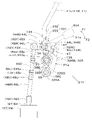
- FIG. 7A is a cross-sectional view showing the locked state of the locking mechanism 114.
- FIG. 7B is a cross-sectional view showing an unlocked state of the lock mechanism 114.
- the operation of the lock mechanism 114 can be changed between a locked state that restrains the movement of the operating member 41 and an unlocked state that allows the movement of the operating member 41.
- the lock mechanism 114 includes engaging portions 45L, 45R, a lock body 126, a lock support shaft 128, and a drive portion 131.
- the first engaging portion 45L is provided so as to project rearward from the first base portion 44L of the first traveling lever 41L outward in the radial direction of the first base portion 44L and the operation support shaft 34.
- the second engaging portion 45R is provided so as to project rearward from the second base portion 44R of the second traveling lever 41R to the outside in the radial direction of the second base portion 44R and the operation support shaft 34. Therefore, the first engaging portion 45L rotates integrally with the first traveling lever 41L, and the second engaging portion 45R rotates integrally with the second traveling lever 41R. That is, the engaging portions 45L and 45R rotate integrally with the operating member 41.
- a first engaging groove 46L is formed at the tip of the first engaging portion 45L.
- a second engaging groove 46R is formed at the tip of the second engaging portion 45R.
- the first engaging groove 46L and the second engaging groove 46R are recessed in the radial direction of the operation support shaft 34 from the rear to the front.
- the first engaging groove 46L and the second engaging groove 46R are grooves that are open to the rear side, and are on the operation support shaft 34 side from the tips of the first engaging portion 45L and the second engaging portion 45R. It is dented.
- an inclined surface forming a taper that widens the distance between the first engaging groove 46L and the second engaging groove 46R above and below the front portion toward the rear. 47 is provided.
- a mounting plate 129 is fixed to the lower base portion 32c of the third connecting member 32.
- the mounting plate 129 projects rearward from the lower base portion 32c.
- Each plate surface of the mounting plate 129 faces up or down.
- the first support piece 129B and the second support piece 129C are fixed to the upper surface of the mounting plate 129 so as to project upward.
- the first support piece 129B and the second support piece 129C are provided so as to be spaced apart from each other in the machine width direction K2.
- the lock support shaft 128 is supported by the lower base portion 32c via the mounting plate 129 by being inserted over the first support piece 129B and the second support piece 129C. Further, the lock support shaft 128 is arranged below the operation support shaft 34. Further, the lock support shaft 128 has an axial center extending in the machine width direction K2, and is arranged in parallel with the operation support shaft 34.
- the lock body 126 has a base cylinder 126A, a lock arm 126B, and a lock pin 126C.
- the base cylinder 126A constitutes a lower end portion (one end portion) of the lock body 126.
- the base cylinder 126A is rotatably mounted around the lock support shaft 128 around its axis. That is, one end of the lock body 126 is rotatably supported by the lock support shaft 128. Further, the lock body 126 is arranged below the electrical components 140L and 140R at predetermined intervals.
- the lock arm 126B is provided on the base cylinder 126A so as to project outward and upward in the radial direction thereof. Further, the lock arm 126B bends forward as it goes upward.
- the lock arm 126B and the base cylinder 126A are provided at positions corresponding to each other between the first engaging portion 45L and the second engaging portion 45R. The lock arm 126B swings in the front-rear direction as the base cylinder 126A rotates around the axis of the lock support shaft 128.
- the lock pin 126C is provided in the intermediate portion between one end located below the lock arm 126B and the other end located above.
- the lock pin 126C is fixed to the lock arm 126B in a state of penetrating the middle portion of the lock arm 126B to the left and right. That is, the lock pin 126C protrudes from the intermediate portion of the lock arm 126B on both sides in the body width direction K2.
- the left protruding length and the right protruding length of the lock pin 126C from the lock arm 126B are the same.
- a tubular body 127 is provided between the first base 44L of the first traveling lever 41L and the second base 44R of the second traveling lever 41R.
- the tubular body 127 is mounted around the first shaft 34A of the operation support shaft 34 and is fixed to the first shaft 34A.
- the drive unit 131 applies a driving force to the upper end portion (the other end portion) of the lock body 126, and has an interlocking portion 132 and a connecting member 133.
- the interlocking portion 132 is provided on the tubular body 127 mounted around the operation support shaft 34 so as to project radially outward and diagonally upward of the tubular body 127. That is, the interlocking portion 132 is provided on the operation support shaft 34 via the tubular body 127.
- the cylinder 127 and the interlocking portion 132 rotate integrally with the operation support shaft 34.
- the interlocking portion 132 may be provided on the operation support shaft 34 itself.
- the connecting member 133 is arranged above the operation support shaft 34, and connects the interlocking portion 132 and the lock body 126. Specifically, the front end portion of the connecting member 133 is rotatably connected to the interlocking portion 132 via a pin 135. The rear end portion of the connecting member 133 is rotatably connected to the upper end portion of the lock body 126 via a pin 136.
- the lock body 126 is at the engaging position P1 that engages with the first engaging portion 45L and the second engaging portion 45R and restrains the movement of the operating member 41. Further, the lock mechanism 114 is in a locked state that restrains the movement of the operating member 41.
- the positions of the lock pin 126C with respect to the first engaging groove 46L and the second engaging groove 46R can be adjusted. Further, by adjusting the contact position between the first stopper 98 and the contact member 97, the insertion depth of the lock pin 126C with respect to the first engagement groove 46L and the second engagement groove 46R can be adjusted.
- the lock lever 50 is operated by tilting it backward (on the driver's seat 6 side in FIG. 24 or the like) to position it at the second position X2. Then, the drive unit 131 transmits an operating force for changing the position of the lock lever 50 to the upper end portion of the lock body 126 as a drive force, and rotates the lock body 126 around the axis of the lock support shaft 128. Let me. Specifically, the operating support shaft 34, the cylinder 127, and the interlocking portion 132 rotate in the unlocking direction F2 due to the operating force applied to the lock lever 50. Then, as shown in FIG.
- the interlocking portion 132 moves the connecting member 133 rearward, and the connecting member 133 moves the upper end portion of the lock arm 126B rearward. Therefore, the lock arm 126B rotates (swings) in the unlocking direction F2 around the axis of the lock support shaft 128. Then, the lock pin 126C moves rearward and separates from the first engaging groove 46L and the second engaging groove 46R.
- the vertical movement of the first engaging portion 45L and the second engaging portion 45R is permitted (restraint release), so that the movements of the first traveling lever 41L and the second traveling lever 41R are also permitted, and these operations are performed.
- the swing operation of the member 41 becomes possible. That is, in FIG. 7B, the lock body 126 is in the disengagement position P2 where the first engaging portion 45L and the second engaging portion 45R are disengaged to allow the operation member 41 to move. Further, the lock mechanism 114 is in an unlocked state that allows the operation member 41 to move.
- the lock lever 50 is operated to stand upward to be positioned at the first position X1.
- the drive unit 131 transmits an operating force for changing the position of the lock lever 50 to the upper end portion of the lock body 126 as a drive force, and rotates the lock body 126 around the axis of the lock support shaft 128.
- the operating support shaft 34, the cylinder 127, and the interlocking portion 132 rotate in the locking direction F1 due to the operating force applied to the lock lever 50.
- the interlocking portion 132 moves the connecting member 133 forward
- the connecting member 133 moves the upper end portion of the lock arm 126B forward. Therefore, the lock arm 126B rotates (swings) in the lock direction F1 around the axis of the lock support shaft 128.
- the lock pin 126C moves forward and engages with the first engaging groove 46L and the second engaging groove 46R.
- the lock body 126 engages with the first engaging portion 45L and the second engaging portion 45R from the disengagement position P2 shown in FIG. 7B and restrains the movement of the operating member 41 as shown in FIG. 7A.
- the position is changed (moved) to the alignment position P1.
- the lock mechanism 114 returns to the locked state of the operation member 41.
- the lock body 126 can be repositioned to the engagement position P1 shown in FIG. 7A and the disengagement position P2 shown in FIG. 7B.
- the lock mechanism 114 is closer to the second cover 26B side, that is, the driver's seat 6 side (rear) from the operation support shaft 34. That is, the lock mechanism 114 is located on the driver's seat 6 side (rear) from a position equivalent to the operation support shaft 34 (position in the front-rear direction K1) when viewed from the machine body width direction K2.
- the lock mechanism 114 is on the second cover 26B side, that is, the driver's seat 6 with respect to the portion (front end portion) located on the most front side (first cover 26A side) of the operation support shaft 34. It is located on the side (rear).
- the lock mechanism 114 is closer to the second cover 26B side, that is, the driver's seat 6 side (rear) from the operation support shaft 34. That is, the lock mechanism 114 is located on the driver's seat 6 side (rear) from a position equivalent to the operation support shaft 34 (position in the front-rear direction K1) when viewed from the machine body width direction K2.
- a part of the lock mechanism 114 (the front end portion of the interlocking portion 132) overlaps with the operation support shaft 34 in the front-rear direction K1. It is located rearward of the front end of the operation support shaft 34.
- the other members and other parts other than the interlocking portion 132 of the lock mechanism 114 and the front end portion of the connecting member 133 are from the operation support shaft 34 to the second cover 26B side (driver's seat 6 side). I'm close to. That is, the rear end portion, the lock body 126, the lock support shaft 128, and the engaging portions 45L and 45R of the connecting member 133 are located in the driver's seat from the same position as the operation support shaft 34 when viewed from the machine body width direction K2. It is located on the 6th side.
- the other members and other parts other than the interlocking portion 132 of the lock mechanism 114 and the front end portion of the connecting member 133 are on the second cover 26B side with respect to the front end portion of the operation support shaft 34, that is, It is located on the driver's seat 6 side (rear).
- the lock body 126, the lock support shaft 128, and the engaging portions 45L and 45R are always arranged on the second cover 26B side with respect to the operation support shaft 34. That is, the lock support shaft 128 and the engaging portions 45L and 45R are always located on the driver's seat 6 side (rear) with respect to the operation support shaft 34 when viewed from the machine body width direction K2. Further, each part of the lock mechanism 114 is arranged in the vicinity of the joint portion 26X of the first cover 26F and the second cover 26B.
- each part of the lock mechanism 114 can be moved from the operation support shaft 34 to the second cover 26B side (driver's seat 6 side) in both the locked state and the unlocked state. You may approach to. Further, in at least one of the locked state and the unlocked state, each part of the lock mechanism 114 may be closer to the driver's seat 6 side than the operation support shaft 34. Further, all or most of the locking mechanism 114 may be arranged on the second cover 26B side from the joint portion 26X of the first cover 26F and the second cover 26B.
- the lock mechanism 114 is usually covered with a cover 26. However, as shown in FIG. 2, the lock mechanism 114 is exposed by removing the second cover 26B from the support frame 25, the first cover 26F, and the like. Further, as shown in FIG. 1, the lock mechanism 114 is also exposed by opening the lid 26g provided on the rear surface 26a of the second cover 26B and opening the window 26c. That is, the second cover 26B is provided with the lock mechanism 114 so as to be exposed on the driver's seat 6 side.
- the operating force of the lock lever 50 is used as the driving force of the driving unit 131, but instead of this, the driving force is generated by the actuator 139 provided in the driving unit 131 as shown in FIGS. 8A and 8B. You may.
- FIG. 8A is a cross-sectional view showing the locked state of the lock mechanism 114 of the modified example.
- FIG. 8B is a cross-sectional view showing an unlocked state of the lock mechanism 114 of the modified example.
- the drive unit 131 of the lock mechanism 114 shown in FIGS. 8A and 8B has an actuator 139 that generates a driving force.
- the actuator 139 may be, for example, a hydraulic actuator such as a hydraulic cylinder, or an electric actuator such as a solenoid.
- a tubular body 137 is provided around the operation support shaft 34.
- the cylinder 137 is rotatable relative to the operation support shaft 34.
- the cylinder 137 is provided with interlocking portions 132a and 132b.
- the interlocking portion 132a projects radially outward and diagonally upward of the tubular body 137.
- the front end portion of the connecting member 133 is rotatably connected to the interlocking portion 132a via the pin 135.
- the interlocking portion 132b projects radially outward and diagonally downward of the tubular body 137.
- a pin 138a included in the link mechanism 138 is engaged with the elongated hole 132c formed in the interlocking portion 132b.
- the link mechanism 138 is connected to the actuator 139a of the actuator 139.
- the link mechanism 138 transmits the driving force generated by the actuator 139 to the interlocking portion 132b.
- the main body portion 139b of the actuator 139 is fixed to, for example, the front base portion 32f (FIG. 4) of the third connecting member 32.
- An operating tool such as a button, a switch, or a lever for driving the actuator 139 may be provided on the operating table 23 or the like. Further, a control unit for controlling the operation of the actuator 139 may also be provided on the operation table 23.
- the actuator 139 In the state shown in FIG. 8A, the actuator 139 generates a driving force that causes the actuator 139a to project toward the rear A2 of the machine body 2 by an elastic member (not shown) such as a built-in spring. Therefore, the driving force of the actuator 139 is sequentially transmitted to the link mechanism 138, the interlocking portion 132b, the tubular body 137, the interlocking portion 132a, the connecting member 133, and the lock body 126, and the lock body 126 rotates in the lock direction F1. It is in a state. Further, the lock pin 126C is in a state of being engaged with the engaging grooves 46L and 46R. That is, in FIG. 8A, the lock body 126 is in the engaging position P1, and the lock mechanism 114 is in a state of locking the operation member 41.
- the actuator 139 is driven to move the actuator 139a to the front A1 of the machine body 2 (pulled state into the main body portion 139b). Then, the driving force is sequentially transmitted to the interlocking portion 132b, the tubular body 137, the interlocking portion 132a, the connecting member 133, and the locking body 126, and the locking body 126 rotates in the unlocking direction F2 as shown in FIG. 8B. .. Then, the lock pin 126C is disengaged from the engaging grooves 46L and 46R. That is, in FIG. 8B, the lock body 126 is moved to the release position P1 and the lock mechanism 114 is in a state of unlocking the operation member 41.
- the link mechanism 138, the interlocking portions 132a and 132b, the tubular body 137, and the connecting member 133 are omitted, and the actuator 139a of the actuator 139 is directly or indirectly connected to the upper end portion of the lock body 126.
- the driving force of the actuator 139 is directly or indirectly applied to the lock body 126, the lock body 126 rotates in the lock direction F1 or the unlock direction F2, and the lock pin 126C with respect to the engagement grooves 46L and 46R. It can be engaged or disengaged.
- FIG. 9 is a perspective view of the upper part of the internal structure of the cockpit 23 as viewed from the rear A2 (driver's seat 6 side).
- FIG. 10 is a perspective view of the upper part of the internal structure of the cockpit 23 as viewed from the front A1 (working device 4 side) of the machine body 2.
- FIG. 11 is an enlarged perspective view of the vicinity of the lock mechanism 314 shown in FIG.
- the internal structure of the cockpit 23 includes a support frame 25 that serves as a skeleton of the cockpit 23.
- the first cover 26F and the second cover 26B shown in FIG. 1 and the like are fixed to the support frame 25 by fastening members (not shown) such as bolts and nuts.
- the support frame 25 includes a first vertical member 27 constituting the left portion, a second vertical member 28 constituting the right portion, and a connecting body 29 connecting the two vertical members 27 and 28.
- the first vertical member 27 and the second vertical member 28 are formed in a plate shape.
- the first vertical member 27 and the second vertical member 28 are erected on the machine body 2 with their respective plate surfaces facing the machine body width direction K2. Further, the first vertical member 27 and the second vertical member 28 face each other with a predetermined interval in the machine width direction K2.
- the connecting body 29 is provided between the upper portions of the first vertical member 27 and the second vertical member 28.
- the connecting body 29 has a first connecting material 30, a second connecting material 31, and a third connecting material 32 (FIG. 9). In FIGS. 10 and 11, for convenience, the third connecting member 32 is not shown.
- the first connecting member 30 is connected to the upper part of the first vertical member 27.
- the second connecting member 31 is connected to the upper part of the second vertical member 28.
- the first connecting member 30 and the second connecting member 31 are provided at intervals in the machine width direction K2.
- the third connecting material 32 connects the first connecting material 30 and the second connecting material 31.
- the first connecting member 30 is arranged on the side of the second vertical member 28 with respect to the first vertical member 27 and is connected to the first vertical member 27.
- the first connecting member 30 has a first wall 30a, a second wall 30b, and a third wall 30c.
- the first wall 30a is fixed along the first vertical member 27.
- a first bearing cylinder 69L is arranged below the first wall 30a.
- the first bearing cylinder 69L is provided through the first vertical member 27 in a penetrating manner, and has an axial center extending in the machine width direction K2.
- the second wall 30b extends from the front end portion of the first wall 30a toward the inside of the aircraft.
- a first support cylinder 68L is provided on the second wall 30b in a penetrating manner.
- the first support cylinder 68L has an axial center extending in the front-rear direction K1.
- the second connecting member 31 is arranged on the side of the first vertical member 27 with respect to the second vertical member 28 and is connected to the second vertical member 28.
- the second connecting member 31 has a first wall 31a, a second wall 31b, and a third wall 31c.
- the first wall 31a is fixed along the second vertical member 28.
- a second bearing cylinder 69R is arranged below the first wall 31a.
- the second bearing cylinder 69R is provided in a penetrating shape on the second vertical member 28, and has an axial center extending in the machine width direction K2.
- the second wall 31b extends from the front end portion of the first wall 31a toward the inside of the aircraft.
- a second support cylinder 68R is provided on the second wall 31b in a penetrating manner.
- the second support cylinder 68R has an axial center extending in the front-rear direction K1.
- the third wall 30c of the first connecting member 30 is fixed in a protruding shape from the rear surface of the right end portion of the second wall 30b toward the rear A2.
- the third wall 31c of the second connecting member 31 is fixed so as to project from the rear surface of the left end portion of the second wall 31b toward the rear A2.
- An operation support shaft (first shaft) 34 is provided on the upper part of the support frame 25.
- the operation support shaft 34 has an axial center extending in the machine width direction K2.
- the operation support shaft 34 is rotatably supported by the first vertical member 27 and the second vertical member 28 of the support frame 25 around the axis thereof.
- the operation support shaft 34 has a first shaft portion 34A and a second shaft portion 34B (FIG. 10).
- the first shaft portion 34A is inserted through the first bearing cylinder 69L, and the first wall 30a and the third wall 30c of the first connecting member 30 and the third wall 31c of the second connecting member 31 are inserted. And penetrates.
- the first shaft portion 34A is rotatably supported around the axis of the first bearing cylinder 69L by the first bearing cylinder 69L and the third walls 30c and 31c.
- the second shaft portion 34B is arranged on the right side B2 of the first shaft portion 34A and on the rear A2.
- the second shaft portion 34B is inserted with the second bearing cylinder 69R.
- the second shaft portion 34B is supported by the second bearing cylinder 69R so as to be rotatable around the axis of the second bearing cylinder 69R.
- the first shaft portion 34A and the second shaft portion 34B are arranged at intervals in the machine width direction K2. As shown in FIG. 11 and the like, a connecting member 11X is provided between the first shaft portion 34A and the second shaft portion 34B.
- the first shaft portion 34A and the second shaft portion 34B are integrally rotatably connected by a connecting member 11X.
- the operation support shaft 34 including the first shaft portion 34A and the second shaft portion 34B is formed by the first vertical member 27, the second vertical member 28, the first connecting member 30, and the second connecting member 31. It is supported.
- the operation support shaft 34 may be composed of one shaft.
- the connecting member 11X connects the first side wall 11A connected to the first shaft portion 34A, the second side wall 11B connected to the second shaft portion 34B, and the first side wall 11A and the second side wall 11B. It has a portion 11C and an extension portion 11D extending upward from the second side wall 11B.
- the first side wall 11A and the second side wall 11B are arranged at predetermined intervals in the body width direction K2.
- the connecting portion 11C connects the rear end portions of the first side wall 11A and the second side wall 11B to each other.
- a connection cylinder 64 is provided on the first side wall 11A.
- the right end portion of the first shaft portion 34A is inserted into the connection cylinder 64 and fixed to the connection cylinder 64.
- the first shaft portion 34A and the first side wall 11A can be integrally rotated.
- the extending portions 11D of the connecting member 11X are provided with the plates 11E and 11F and the first spring hooking portion 70 in a protruding shape on the left B1.
- the first plate 11E is arranged in front of the second plate 11F in A1.
- the first spring hooking portion 70 is composed of a pin and protrudes from the extending portion 11D toward the first shaft portion 34A (left side B1).
- a second spring hooking portion 72 is provided below the second wall 31b of the second connecting member 31.
- the second spring hooking portion 72 is composed of a bending pin and is fixed to the holding plate 100.
- the holding plate 100 is fixed to the plate surface of the second vertical member 28 on the side of the machine body, and protrudes forward A1 from the second vertical member 28.
- the second spring hooking portion 72 protrudes from the holding plate 100 to the left B1 and then bends toward the front A1.
- a tubular body 39L is mounted on the radial outer side of the left portion of the first shaft portion 34A (between the first wall 30a and the third wall 30c of the first connecting member 30). There is.
- the tubular body 39L is fixed to the first shaft portion 34A by a pin or the like, and can rotate integrally with the first shaft portion 34A.
- a cylindrical spacer 39R is mounted on the radial outer side of the right portion of the first shaft portion 34A (between the third wall 31c of the second connecting member 31 and the connecting member 11X). The spacer 39R is fixed to the first shaft portion 34A by a pin or the like.
- control valve 35 is provided on the control table 23.
- the control valve 35 is an aggregate of a plurality of control valves V1 to V10 for controlling the hydraulic actuator provided in the working machine 1, and is provided between the lower portions of the first vertical member 27 and the second vertical member 28.
- Each control valve V1 to V10 is a direct acting spool type direction switching valve.
- the spools of the control valves V1 to V10 are held in the neutral position by the urging force of the urging spring housed in the valve body, and are operated up and down from the neutral position against the urging force of the urging spring.
- the plurality of control valves are the first control valve V1 to the tenth control valve V10.
- the first control valve V1 to the tenth control valve V10 are mechanically operated direction switching valves whose spools can be manually switched.
- the first control valve V1 is a speed change control valve that controls a swash plate angle cylinder (not shown) that changes the tilt angle of the swash plate of the first traveling motor M1 and the second traveling motor M2 (FIG. 25).
- the second control valve V2 is a swivel control valve that controls the swivel motor M3 (FIG. 24).
- the third control valve V3 is an arm control valve that controls the arm cylinder C4 (FIG. 24).
- the fourth control valve V4 is a first traveling control valve (traveling control valve) that controls the first traveling motor M1 (FIG. 24).
- the fifth control valve V5 is a control valve for a dozer that controls the dozer cylinder C1 (FIG. 24).
- the sixth control valve V6 is a spare control valve that controls the hydraulic attachment.
- the seventh control valve V7 is a second traveling control valve (traveling control valve) that controls the second traveling motor M2.
- the eighth control valve V8 is a swing control valve that controls the swing cylinder C2 (FIG. 24).
- the ninth control valve V9 is a bucket control valve that controls the bucket cylinder C5 (FIG. 24).
- the tenth control valve V10 is a boom control valve that controls the boom cylinder C3 (FIG. 24).
- the third control valve V3, the ninth control valve V9, and the tenth control valve V10 are work control valves that control the hydraulic actuator that drives the work device 4 (FIG. 24).
- the control table 23 is provided with an operation shaft 33 (such as FIG. 9) and a support shaft 37 (such as FIG. 12A described later).
- the operation shaft (second shaft) 33 is provided below the connecting body 29 and the operation support shaft 34 and above the control valve 35.
- the support shaft (third shaft) 37 is provided between the operation support shaft 34 and the operation shaft 33.
- the operation shaft 33 and the support shaft 37 each have an axial center extending in the machine width direction K2, and are provided over the first vertical member 27 and the second vertical member 28. That is, the operation shaft 33 and the support shaft 37 are provided in parallel with the operation support shaft 34.
- the operation shaft 33 is supported by the first vertical member 27 and the second vertical member 28 so as to be rotatable around the axis.
- the right portion of the operation shaft 33 projects outward from the second vertical member 28.
- the support shaft 37 is supported by the first vertical member 27 and the second vertical member 28.
- a first rotating cylinder 38A, a third rotating cylinder 38C, and a fourth rotating cylinder 38D are mounted on the radial outer side of the operating shaft 33.
- the third rotating cylinder 38C rotates integrally with the operating shaft 33, and the first rotating cylinder 38A and the fourth rotating cylinder 38D rotate relative to the operating shaft 33.
- a fifth rotating cylinder 38E is mounted on the radial outer side of the support shaft 37.
- a second rotating cylinder 38B is mounted on the radial outer side of the central portion of the fifth rotating cylinder 38E (see FIG. 12A and the like).
- a first relay piece 91A is provided in a protruding shape on the rear A2 at the rear portion of the first rotating cylinder 38A.
- Connecting portions 91L and 91R are provided on the left and right ends of the second rotating cylinder 38B so as to project rearward A2.
- a third relay piece 91C is provided so as to project rearward A2.
- Connecting portions 91P and 91Q are provided on the left and right ends of the fifth rotating cylinder 38E so as to project rearward A2.
- a first arm 39A is provided on the front portion of the first rotating cylinder 38A so as to project forward A1.
- a second arm 39B is provided on the front portion of the second rotating cylinder 38B so as to project forward A1.
- a third arm 39C is provided on the front portion of the third rotating cylinder 38C so as to project forward A1.
- a fourth arm 39D is provided on the front portion of the fourth rotating cylinder 38D so as to project forward A1.
- a fifth arm 39E is provided on the front portion of the fifth rotating cylinder 38E so as to project forward A1.
- the first rotating cylinder 38A is connected to the spool S2 of the second control valve V2 via the arm 39A and the link 40A.
- the second rotating cylinder 38B is connected to the spool S3 of the third control valve V3 via the arm 39B and the link 40B.
- the third rotating cylinder 38C is connected to the spool S5 of the fifth control valve V5 via the arm 39C and the link 40C.
- the fourth rotating cylinder 38D is connected to the spool S9 of the ninth control valve V9 via the arm 39D and the link 40D.
- the fifth rotating cylinder 38E is connected to the spool S10 of the tenth control valve V10 via the arm 39E and the link 40E.
- the control table 23 is provided with a plurality of levers and pedals for operating the work device 4, the dozer device 7, the traveling device 3 (FIG. 24), and other devices provided in the work machine 1.
- a dozer lever (second operating member) 66 for operating the dozer device 7 is provided on the right side B2 of the control table 23.
- the base of the dozer lever 66 is fixed to the right portion of the operating shaft 33.
- An accelerator lever 67 for operating the rotation speed of the prime mover Eg is provided on the left side B1 of the control table 23.
- a first pedal support portion and a second pedal support portion are provided below the first vertical member 27 (see FIG. 24, reference numeral omitted).
- the first pedal support portion supports a speed change pedal (not shown) for operating the first control valve V1 (FIG. 9).
- the second pedal support portion supports an SP pedal (not shown) for operating the sixth control valve V6 (FIG. 9).
- a third pedal support portion is provided at the lower portion of the second vertical member 28 (not shown).
- the third pedal support portion supports a swing pedal (not shown) for operating the eighth control valve V8 (FIG. v).
- an operation member (first operation member) 41 and a control member (third operation member) 71 are provided above the control table 23.
- the operation member 41 constitutes a travel lever for operating the travel device 3 (travel control valve).
- the operation member 41 is arranged at the upper part of the control table 23 and at the center of the aircraft width direction K2.
- the operating member 41 includes a first traveling lever 41L and a second traveling lever 41R.
- the first traveling lever 41L and the second traveling lever 41R are arranged side by side in the machine width direction K2.
- the first traveling device 3L is operated by the first traveling lever 41L
- the second traveling device 3R is operated by the second traveling lever 41R.
- first traveling lever 41L is located inside the aircraft of the first steering lever 71L, which will be described later.
- the second traveling lever 41R is located inside the aircraft of the second steering lever 71R, which will be described later, and is located on B2 to the right of the first traveling lever 41L.
- the first traveling lever 41L has a lever main body 43L having a grip 42L at the tip portion (upper portion) and a tubular first base portion 44L (FIG. 10 or the like) provided at the lower portion of the lever main body 43L.
- the first base portion 44L is arranged between the first connecting member 30 and the second connecting member 31.
- the first shaft portion 34A of the operation support shaft 34 is inserted through the first base portion 44L. That is, the first base portion 44L is arranged around the first shaft portion 34A.
- the first base portion 44L is supported around the axis of the first shaft portion 34A so as to be rotatable relative to the first shaft portion 34A.
- the first traveling lever 41L is rotatably supported by the operation support shaft 34 around the axis of the operation support shaft 34, and can be oscillated in the front-rear direction K1.
- the first base portion 44L is provided with a first arm protrusion 45X made of a plate material so as to project forward A1.
- the first arm protrusion 45X rotates integrally with the first traveling lever 41L.
- One end (upper part) of the connecting rod 48L is connected to the first arm protrusion 45X via a ball joint 49L.
- the other end (lower part) of the connecting rod 48L is connected to the spool S4 of the fourth control valve V4 via the connecting block 48X.
- the second traveling lever 41R includes a lever body 43R having a grip 42R at the tip (upper part) and a tubular second base portion 44R (lower part) provided at the base (lower part) of the lever body 43R.
- the second base portion 44R is arranged between the first connecting member 30 and the second connecting member 31.
- the first shaft portion 34A of the operation support shaft 34 is inserted through the second base portion 44R. That is, the second base portion 44R is arranged around the first shaft portion 34A.
- the second base portion 44R is supported around the axis of the first shaft portion 34A so as to be rotatable relative to the first shaft portion 34A.
- the second traveling lever 41R is rotatably supported by the operation support shaft 34 around the axis of the operation support shaft 34, and can be swung back and forth.
- the second base portion 44R is provided with a second arm protrusion 45Y made of a plate material so as to project forward A1.
- the second arm protrusion 45Y is arranged side by side in a direction parallel to the axial direction of the operation support shaft 34 with the first arm protrusion 45X. Further, the second arm protrusion 45Y rotates integrally with the second traveling lever 41R.
- One end side (upper part) of the connecting rod 48R is connected to the second arm protrusion 45Y via a ball joint 49R.
- the other end side (lower part) of the connecting rod 48R is connected to the spool S7 of the seventh control valve V7 via the connecting block 48Y.
- the control member 71 is a lever that operates the work device 4 and the machine body 2.
- the control member 71 includes a first control lever 71L and a second control lever 71R provided on B2 to the right of the first control lever 71L.
- the first control lever 71L and the second control lever 71R are arranged on the upper part of the control table 23 and outside the machine body from the operation member 41.
- the first control lever 71L is arranged on the outer side (left side) of the first traveling lever 41L.
- the second control lever 71R is arranged on the outer side (right side) of the second traveling lever 41R.
- the aircraft 2, the arm 16, the boom 15, and the bucket 17 are operated by the control levers 71L and 71R.
- the first control lever 71L has a grip 78L (FIG. 2) at the tip (upper part).
- the base portion (lower portion) of the first control lever 71L is supported by the support frame 25 via the first support body 77L (FIG. 9) so as to be swingable in an arbitrary swing direction.
- the second control lever 71R has a grip 78R (FIG. 2) at the tip end (upper portion).
- the base portion (lower portion) of the second control lever 71R is supported by the support frame 25 via the second support 77R (FIG. 9) so as to be swingable in an arbitrary swing direction.
- the swing directions of the first control lever 71L and the second control lever 71R are the front-rear direction K1, the machine body width direction K2, and the diagonal direction between the front-rear direction K1 and the machine body width direction K2.
- the first support 77L arranged below the first control lever 71L has a first bracket 81L and a first lever fixing portion 82L.
- the first bracket 81L is rotatably supported by the first bearing cylinder 69L via a first pivot axis (not shown) parallel to the front-rear direction K1.
- the first lever fixing portion 82L is rotatably supported by the first bracket 81L via the second pivot shaft 80L parallel to the machine body width direction K2 in a state of being inserted inside the first bracket 81L.
- the base of the first control lever 71L is fixed to the upper surface of the first lever fixing portion 82L.
- a connecting portion 88L is provided on the rear surface of the first lever fixing portion 82L so as to project rearward A2.
- a connecting piece 86L is provided on the left B1 in a protruding shape on the left rear portion of the first bracket 81L.
- the upper end portion of the first interlocking member 89A is connected to the connecting piece 86L.
- the lower end of the first interlocking member 89A is connected to the first relay piece 91A.
- the second support 77R arranged below the second control lever 71R has a second bracket 81R and a second lever fixing portion 82R.
- the second bracket 81R is rotatably supported by the second bearing cylinder 69R via a third pivot axis (not shown) parallel to the front-rear direction K1.
- the second lever fixing portion 82R is rotatably supported by the second bracket 81R via the fourth pivot axis 80R parallel to the machine width direction K2 in a state of being inserted inside the second bracket 81R.
- the base of the second control lever 71R is fixed to the upper surface of the second lever fixing portion 82R.
- a connecting portion 88R is provided on the rear surface of the second lever fixing portion 82R so as to project rearward A2.
- a connecting piece 86R is provided on the left B1 in a protruding shape on the left rear portion of the second bracket 81R.
- the upper end of the third interlocking member 89C is connected to the connecting piece 86R.
- the lower end of the third interlocking member 89C is connected to the third relay piece 91C.
- An operation switching mechanism 315 is provided below the control levers 71L and 71R.
- the operation switching mechanism 315 transmits the swing operation force of the first control lever 71L and the second control lever 71R in the front-rear direction K1 to the control valves V3 and V10, and the operation switching mechanism 315 transmits the swing operation force of the first control lever 71L and the second control lever 71R.
- It is a mechanism for switching the operation target, and is also called TPSS (Two Pattern Selective System).
- the operation switching mechanism 315 includes a second rotating cylinder (rotating member) 38B, a fifth rotating cylinder (rotating member) 38E, a second interlocking member (link member) 89B, and a fourth interlocking member (link member) 89D.
- the upper end of the second interlocking member 89B is connected to the connecting portion 88L of the first lever fixing portion 82L.
- the lower end portion of the second interlocking member 89B can be selectively connected to either the connecting portion 91L of the second rotating cylinder 38B or the connecting portion 91P of the fifth rotating cylinder 38E.
- the upper end of the fourth interlocking member 89D is connected to the connecting portion 88R of the second lever fixing portion 82R.
- the lower end portion of the fourth interlocking member 89D can be selectively connected to either the connecting portion 91Q of the fifth rotating cylinder 38E or the connecting portion 91R of the second rotating cylinder 38B.
- the lower end of the second interlocking member 89B is connected to the connecting portion 91L of the second rotating cylinder 38B, and the lower end of the fourth interlocking member 89D is connected to the fifth rotating cylinder 38E. It is connected to the unit 91Q.
- the third control valve V3 is routed via the second interlocking member 89B, the second rotating cylinder 38B, the second arm 39B, the link 40B, and the like. Spool S3 is pushed and pulled. Then, the arm cylinder C4 is controlled, and the arm 16 swings back and forth.
- the tenth control valve V10 is operated via the fourth interlocking member 89D, the fifth rotating cylinder 38E, the fifth arm 39E, the link 40E, and the like.
- the spool S10 is pushed and pulled.
- the boom cylinder C3 is controlled, and the boom 15 swings back and forth. That is, in this case, the operation targets by swinging the first control lever 71L back and forth are the third control valve V3, the arm cylinder C4, and the arm 16.
- the operation targets of the second control lever 71R by swinging back and forth are the tenth control valve V10, the boom cylinder C3, and the boom 15.
- the lower end of the second interlocking member 89B is connected to the connecting portion 91P of the fifth rotating cylinder 38E, and the lower end of the fourth interlocking member 89D is connected to the connecting portion 91R of the second rotating cylinder 38B. ..
- the tenth control valve V10 is passed through the second interlocking member 89B, the fifth rotating cylinder 38E, the fifth arm 39E, the link 40E, and the like. Spool S10 is pushed and pulled. Then, the boom cylinder C3 is controlled, and the boom 15 swings back and forth.
- the third control valve V3 passes through the fourth interlocking member 89D, the second rotating cylinder 38B, the second arm 39B, the link 40B, and the like.
- the spool S3 is pushed and pulled.
- the arm cylinder C4 is controlled, and the arm 16 swings back and forth. That is, in this case, the operating targets of the first control lever 71L by swinging back and forth are the tenth control valve V10, the boom cylinder C3, and the boom 15.
- the operation targets of the second control lever 71R by swinging back and forth are the third control valve V3, the arm cylinder C4, and the arm 16.
- a lock lever 50A is provided on the left side of the cockpit 23.
- the lock lever 50A is a member that locks (mechanically restrains) the operation member 41 and the control member 71 (mechanically restrains them so that they do not move) and unlocks (releases the mechanical restraint so that they move).
- the lock lever 50A is arranged outside the machine body of the first control lever 71L.
- the lock lever 50A has a lever body 52 having a grip 51 attached to the tip thereof. As shown in FIG. 9 and the like, the base portion (lower portion) of the lever main body 52 is fixed to the left end portion of the first shaft portion 34A of the operation support shaft 34. As a result, the lock lever 50A can rotate integrally with the operation support shaft 34, and can be swung up and down.
- the lock lever 50A can be repositioned to the first position X1a (described later in FIG. 12A) and the second position X2a (described later in FIG. 12B) by swinging up and down.
- the first position X1a is a position where the lock lever 50A is raised (a state in which the tip of the lever body 52 faces diagonally upward and backward).
- the second position X2a is a position where the lock lever 50A is lowered (a state in which the tip of the lever body 52 faces diagonally downward and backward).
- the length of the lock lever 50A (the length from the base to the tip of the lever body 52) is shorter than the length of the conventional lock lever as disclosed in Reference 1. Therefore, the lock lever 50A does not protrude into the passage 22 (FIG. 24) regardless of the position of the first position X1a or the second position X2a, and the driver gets on and off the aircraft 2 through the passage 22. It doesn't prevent you from doing it.
- a limit switch 117 is provided in the upper part of the first vertical member 27 in the machine body.
- a contact member 97A is provided on the peripheral surface of the left end portion of the tubular body 39L so as to project outward and upward in the radial direction of the tubular body 39L.
- the first shaft portion 34A of the operation support shaft 34 is inserted inside the cylinder 39L.
- the tubular body 39L and the first shaft portion 34A are fixed. Therefore, the tubular body 39L and the contact member 97 rotate integrally with the operation support shaft 34.
- the limit switch 117 When the limit switch 117 is in the ON state, an ON signal is transmitted from the limit switch 117 to the electronic control device (not shown) provided in the work machine 1. When the limit switch 117 is in the off state, the on signal is not transmitted from the limit switch 117 to the electronic control device. Thereby, the electronic control device can detect the position of the lock lever 50A based on the presence / absence of the ON signal from the limit switch 117.
- An urging member 106 for holding the lock lever 50A at the first position X1a and the second position X2a is provided in the upper part of the second vertical member 28 in the machine body.
- the urging member 106 is a tension coil spring.
- the rear end portion of the urging member 106 is hooked on the first spring hooking portion 70 provided on the connecting member 11X.
- the front end portion of the urging member 106 is hooked on the second spring hooking portion 72 fixed to the second vertical member 28 via the holding plate 100.
- the urging force of the urging member 106 is such that the direction of action on the lock lever 50A is switched between when the lock lever 50A is positioned at the first position X1a and when the lock lever 50A is positioned at the second position X2a. That is, when the lock lever 50A is in the first position X1a, the axis of the urging member 106 is located above the axis of the operation support shaft 34. Therefore, when the lock lever 50A is in the first position X1a (state of FIG. 12A), the urging force of the urging member 106 is in the direction of raising the lock lever 50A (upward direction of the grip 51, locking direction F1 in FIG. 12A, etc.). ) Acts to rotate. By this urging force, the lock lever 50A is held at the first position X1a.
- the axis of the urging member 106 is located below the axis of the operation support shaft 34. Therefore, when the lock lever 50A is in the second position X2a (state in FIG. 12B), the urging force of the urging member 106 is in the direction in which the lock lever 50A is tilted (downward direction of the grip 51, unlocking direction F2 in FIG. 12B, etc.). ) Acts to rotate. By this urging force, the lock lever 50A is held at the second position X2a.
- a stopper 105 is provided on the front A1 of the plate 11E of the connecting member 11X.
- the stopper 105 is a bolt.
- the stopper 105 is screwed into a screw hole (not shown) formed in a through shape in the second wall 31b of the second connecting member 31.
- a lock nut 108 for fixing the position of the stopper 105 is screwed into the stopper 105.
- a stopper 105A is provided on the rear A2 of the connecting member 11X.
- the stopper 105A is a bolt.
- the stopper 105A is fixed to the second vertical member 28 via the holding plate 100A.
- the stopper 105A is screwed into a screw hole (not shown) formed in a through shape in the holding plate 100A.
- a third lock nut 108A for fixing the position of the stopper 105A is screwed into the stopper 105A.
- the positions of the lock lever 50A around the operation support shaft 34 at the first position X1a and the second position X2a can be adjusted.
- the swingable angle of the lock lever 50A (moving angle from one of the first position X1a and the second position X2a to the other) limited by the stoppers 105 and 105A is disclosed in Cited Document 1. It is smaller than the swingable angle of the conventional lock lever.
- a lock mechanism 314 for locking or unlocking the operation member 41 is provided near the center of the operation support shaft 34. Further, on both the left and right sides of the lock mechanism 314, lock mechanisms 112 and 113 for locking or unlocking the control member 71 are provided. Since the structure and operation of the lock mechanisms 112 and 113 for the control member 71 are the same as those of the known technique, the description thereof will be omitted.
- FIG. 12A is a cross-sectional view showing the locked state of the lock mechanism 314.
- FIG. 12B is a cross-sectional view showing an unlocked state of the lock mechanism 314.
- the operation of the lock mechanism 314 can be changed between a locked state that restrains the movement of the operating member 41 and an unlocked state that allows the movement of the operating member 41.
- the lock mechanism 314 has an engaging portion 45L, 45R, a locking body 326, and a driving portion 331.
- the first engaging portion 45L is provided so as to project radially outward from the first base portion 44L and the operation support shaft 34 from the first base portion 44L of the first traveling lever 41L toward the rear A2.
- the second engaging portion 45R is provided so as to project radially outward from the second base portion 44R and the operation support shaft 34 from the second base portion 44R of the second traveling lever 41R toward the rear A2. Therefore, the first engaging portion 45L rotates integrally with the first traveling lever 41L, and the second engaging portion 45R rotates integrally with the second traveling lever 41R. That is, the engaging portions 45L and 45R rotate integrally with the operating member 41.
- a first engaging groove 46L is formed at the tip of the first engaging portion 45L.
- a second engaging groove 46R is formed at the tip of the second engaging portion 45R.
- the first engaging groove 46L and the second engaging groove 46R are recessed in the radial direction of the operation support shaft 34 from the rear A2 toward the front A1.
- the first engaging groove 46L and the second engaging groove 46R are grooves that are open to the rear A2 side, and the operation support shaft 34 is formed from the tips of the first engaging portion 45L and the second engaging portion 45R. It is dented to the side. As shown in FIGS.
- an inclination is formed above and below the front portion of the first engaging groove 46L and the second engaging groove 46R so as to form a taper that widens the distance between the first engaging groove 46L and the second engaging groove 46R toward the rear A2.
- a surface 47 is provided.
- the lock body 326 has a base cylinder 326A, a lock arm 326B, a lock pin 326C, and a groove portion 326D.
- the base cylinder 326A constitutes a lower end portion (one end portion) of the lock body 326.
- the base cylinder 326A is located between the third rotating cylinder 38C and the fourth rotating cylinder 38D, and is rotatably mounted around the operation shaft 33 around the axis thereof. That is, the operation shaft 33 supports the lock body 326 so as to be rotatable relative to the operation shaft 33.
- the lock arm 326B is provided so as to project outward and upward in the radial direction of the base cylinder 326A.
- the lock arm 326B and the base cylinder 326A are integrated.
- the lock arm 326B swings in the front-rear direction K2 as the base cylinder 326A rotates relative to the axis of the operation shaft 33.
- the upper end of the lock arm 326B is located between the first engaging portion 45L and the second engaging portion 45R.
- the lock body 326 is arranged from the operation shaft 33 on the radial outside of the second rotating cylinder 38B and over the operation support shaft 34 via the rear A2.
- a groove 326D recessed toward the rear A2 is provided in the central portion of the lock arm 326B.
- the lock pin (engaged portion) 326C is provided at the upper end portion of the lock arm 326B.
- the lock pin 326C is fixed to the lock arm 326B in a state of penetrating the upper end portion of the lock arm 326B to the left and right. That is, the lock pin 326C protrudes from the lock arm 326B on both sides in the body width direction K2.
- the left protruding length and the right protruding length of the lock pin 326C from the lock arm 326B are the same.
- a tubular body 327 (FIG. 11) is provided between the first base 44L of the first traveling lever 41L and the second base 44R of the second traveling lever 41R.
- the tubular body 327 is attached around the first shaft portion 34A of the operation support shaft 34 and fixed to the first shaft portion 34A.
- the drive unit 331 is a member that applies a driving force to the lock body 326, and has an interlocking unit 332 and a connecting member 333.
- the interlocking portion 332 is provided on the tubular body 327 mounted around the operation support shaft 34 so as to project radially outward and diagonally backward and upward of the tubular body 327. That is, the interlocking portion 332 is provided on the operation support shaft 34 via the tubular body 327.
- the cylinder 327 and the interlocking portion 332 rotate integrally with the operation support shaft 34.
- the interlocking portion 332 may be provided on the operation support shaft 34 itself.
- the connecting member 333 is arranged from above the operation support shaft 34 to below via the rear A2 (outside in the radial direction).
- the connecting member 333 is rotatably connected to the interlocking portion 332 and the lock body 326.
- the upper end portion of the connecting member 333 is rotatably connected to the interlocking portion 332 via the pin 135.
- the lower end of the connecting member 333 is rotatably connected to the lock body 326 via a pin 136.
- the connecting portion (pin 135) between the interlocking portion 332 and the connecting member 333 is located above the operation shaft 33 from the lock pin 326C of the lock body 326.
- the connecting portion (pin 136) between the lock body 326 and the connecting member 333 is located below the lock pin 326C and closer to the operation shaft 33.
- the lock body 326 is at the engaging position P1a that engages with the first engaging portion 45L and the second engaging portion 45R and restrains the movement of the operating member 41. That is, the lock mechanism 314 is in a locked state that restrains the movement of the operating member 41. Further, at this time, the second rotating cylinder 38B is in a state of being inserted into the groove portion 326D without contacting the lock body 326.
- the lock pin 326C is inserted into the first engaging groove 46L and the second engaging groove 46R.
- the depth can be adjusted.
- the lock lever 50A is swung downward to be positioned at the second position X2a.
- the drive unit 331 transmits the operation force for changing the position of the lock lever 50A to the lock body 326 as the drive force, and rotates the lock body 326 around the axis of the operation shaft 33.
- the operating support shaft 34, the tubular body 327, and the interlocking portion 332 rotate in the unlocking direction F2 due to the operating force applied to the lock lever 50A.
- the interlocking portion 332 moves the connecting member 333 diagonally backward and downward, and the connecting member 333 rotates the lock arm 326B downward.
- the lock arm 326B rotates (swings) in the unlocking direction F2 around the axis of the operation shaft 33. Then, the lock pin 326C moves diagonally downward and backward to disengage from the first engaging groove 46L and the second engaging groove 46R. As a result, the vertical movements of the first engaging portion 45L and the second engaging portion 45R are permitted (restraint release), so that the movements of the first traveling lever 41L and the second traveling lever 41R are also permitted, and these operations are performed. The swing operation of the member 41 becomes possible.
- the lock body 326 is at the disengagement position P2a where the first engaging portion 45L and the second engaging portion 45R are disengaged to allow the operation member 41 to move. That is, the lock mechanism 314 is in an unlocked state that allows the operation member 41 to move. At this time, the second rotating cylinder 38B is in a state of being substantially escaped from the groove portion 326D of the lock body 326.
- the lock lever 50A is swung upward to be positioned at the first position X1a.
- the drive unit 331 transmits the operation force for changing the position of the lock lever 50A to the lock body 326 as the drive force, and rotates the lock body 326 around the axis of the operation shaft 33.
- the operation support shaft 34, the cylinder body 327, and the interlocking portion 332 rotate in the lock direction F1 due to the operation force applied to the lock lever 50A.
- the interlocking portion 332 moves the connecting member 333 diagonally forward and upward, and the connecting member 333 rotates the lock arm 326B upward.
- the lock arm 326B rotates (swings) in the lock direction F1 around the axis of the operation shaft 33. Then, the lock pin 326C moves to the front A1 and engages with the first engaging groove 46L and the second engaging groove 46R.
- the lock body 326 engages with the first engaging portion 45L and the second engaging portion 45R from the disengagement position P2a shown in FIG. 12B to restrain the movement of the operating member 41 as shown in FIG. 12A.
- the position is changed (moved) to the alignment position P1a.
- the lock mechanism 314 returns to the locked state of the operation member 41.
- the lock body 326 can be repositioned to the engagement position P1a shown in FIG. 12A and the disengagement position P2a shown in FIG. 12B.
- the operating force of the lock lever 50A is used as the driving force of the driving unit 331, but instead of this, the driving force is generated by the actuator 339 provided in the driving unit 331 as shown in FIGS. 13A and 13B. You may.
- FIG. 13A is a cross-sectional view showing the locked state of the lock mechanism 314 of the modified example.
- FIG. 13B is a cross-sectional view showing an unlocked state of the lock mechanism 314 of the modified example.
- the drive unit 331 of the lock mechanism 314 shown in FIGS. 13A and 13B has an actuator 339 that generates a driving force.
- the actuator 339 may be, for example, a hydraulic actuator such as a hydraulic cylinder, or an electric actuator such as a solenoid.
- the actuator 339 is arranged above the operation support shaft 34 and in front of A1.
- a tubular body 337 is provided around the operation support shaft 34.
- the cylinder 337 is rotatable relative to the operation support shaft 34.
- the cylinder 337 is provided with interlocking portions 332a and 332b.
- the interlocking portion 332a projects radially outward of the tubular body 337 and diagonally upward and backward.
- the front end portion of the connecting member 333 is rotatably connected to the interlocking portion 332a via the pin 135.
- the interlocking portion 332b projects radially outward of the tubular body 337 and diagonally forward and downward. That is, the interlocking portion 332b is arranged below the interlocking portion 332a and in front of A1.
- a pin 338a included in the link mechanism 338 is engaged with the elongated hole 332c formed in the interlocking portion 332b.
- the link mechanism 338 is connected to a pin 338a and an operator 339a projecting downward from the actuator 339.
- the link mechanism 338 transmits the driving force generated by the actuator 339 to the interlocking unit 332b.
- the main body portion 339b of the actuator 339 is fixed to the third connecting member 32 (FIG. 9) via, for example, a bracket.
- An operating tool such as a button, a switch, or a lever for driving the actuator 339 may be provided on the control table 23 or the like. Further, a control unit that controls the operation of the actuator 339 may also be provided on the control table 23.
- the actuator 339 In the state shown in FIG. 13A, the actuator 339 generates a driving force that causes the actuator 139a to protrude downward by an elastic member (not shown) such as a built-in spring. Therefore, the driving force of the actuator 339 is transmitted in order to the link mechanism 338, the interlocking portion 332b, the tubular body 337, the interlocking portion 332a, the connecting member 333, and the lock body 326, and the lock body 326 rotates in the lock direction F1. It is in a state. Further, the lock pin 326C is in a state of being engaged with the engaging grooves 46L and 46R. That is, in FIG. 13A, the lock body 326 is in the engaging position P1a, and the lock mechanism 314 is in a state of locking the operation member 41.
- an elastic member not shown
- the actuator 339 is driven to move the actuator 339a upward (the state of being pulled into the main body 339b). Then, the driving force is sequentially transmitted to the interlocking portion 332b, the tubular body 337, the interlocking portion 32a, the connecting member 333, and the lock body 326, and the lock body 326 rotates in the unlock direction F2 as shown in FIG. 13B. .. Then, the lock pin 326C is disengaged from the engaging grooves 46L and 46R. That is, in FIG. 13B, the lock body 326 is moved to the release position P2a, and the lock mechanism 314 is in a state of unlocking the operation member 41.
- the link mechanism 338, the interlocking portion 332a, 332b, the tubular body 337, and the connecting member 333 are omitted, and the actuator 339a of the actuator 339 is directly or indirectly connected to the end portion of the locking body 3126. You may.
- the driving force of the actuator 339 is directly or indirectly applied to the lock body 326, the lock body 326 rotates in the lock direction F1 or the unlock direction F2, and the lock pin 326C with respect to the engagement grooves 46L and 46R. It can be engaged or disengaged.
- the lock pin 326C is located at the center of the engaging grooves 46L and 46R of the engaging portions 45L and 45R. It is preferable to engage so as to (enter). Specifically, it is preferable that a gap is formed between the lock pin 326C and the groove walls of the engaging grooves 46L and 46R in a state where no operating force is applied to the operating member 41.
- the engaging portions 45L and 45R are at positions slightly rotated upward, and the lock pin 326C is pin 136.
- a lock for unlocking when the lock pin 326C shown in FIG. 12A or the like is in contact with the side wall of the engagement groove 46L, 46R on the side, as compared with the case where the lock pin 326C is not in contact with the side wall of the engagement groove 46L, 46R.
- the operating force of the lever 50A or the driving force of the actuator 339 becomes large, and the lock pin 326C and the engaging portions 45L and 45R are easily worn.
- the base portions 44L and 44R of the operation member 41 are connected to the spools S4 and S7 of the control valves V4 and V7 via not only the engaging portions 45L and 45R but also the arm protrusions 45X and 45Y and the ball joints 49L and 49R.
- the connecting rods 48L and 48R for operating the above are connected. Therefore, as described above, the locking pin 326C is in the engaging groove on the pin 136 side at the position where the engaging portions 45L and 45R are slightly rotated upward in a state where no operating force is applied to the operating member 41.
- control valve V4 When in contact with the side walls of 46L and 46R, the control valve V4 is operated by swinging the operating member 41 from the neutral position to the front A1 and swinging the operating member 41 from the neutral position to the rear A2. , The timing at which the spools S4 and S7 of V7 start to move and the operating load are different from each other.
- the control base 23 adjusts the locked state of the lock mechanism 314, that is, the engaged state of the engaging grooves 46L and 46R of the engaging portions 45L and 45R and the lock pin (engaged portion) 326C. It has a lock adjustment structure.
- the lock adjusting structure includes connecting rods 48L, 48R, ball joints 49L, 49R, arm protrusions 45X, 45Y and the like shown in FIGS. 10 and 13A.
- the arm protrusions 45X and 45Y are located on the radial outer side and the front A1 of the operation support 34 from different positions from the engagement portions 45L and 45R in the base portions 44L and 44R of the operation members 41L and 41R, respectively. It is provided in a protruding shape.
- the ball joints 49L and 49R are rotatably connected to the arm protrusions 45X and 45Y.
- the upper end sides of the connecting rods 48L and 48R are connected to the ball joints 49L and 49R, respectively.
- the lower ends of the connecting rods 48L and 48R are connected to the spools S4 and S7 of the control valves V4 and V7 via the connecting blocks 48X and 48Y, respectively.
- the connecting rods 48L and 48R are rotatably connected to the connecting blocks 48X and 48Y around the axis of the connecting rods 48L and 48R, respectively.
- the connecting blocks 48X and 48Y are rotatably connected to the spools S4 and S7.
- the connecting rods 48L and 48R and the ball joints 49L and 49R are screwed together. Specifically, a male threaded portion 48q is formed on the outer peripheral surface of the upper end portions of the connecting rods 48L and 48R.
- the ball joints 49L and 49R are provided with tubular portions 49X and 49Y so as to project downward, and female threaded portions 49p are formed on the inner peripheral surfaces of the tubular portions 49X and 49Y.
- FIG. 15 is a diagram showing another example of the lock adjustment structure.
- the lock adjusting structure includes connecting rods 48L, 48R, ball joints 49L, 49R, and arm protrusions 45X, 45Y, as well as a relay member 340.
- the connecting structure of the arm protrusions 45X and 45Y and the ball joints 49L and 49R, and the connecting structure of the connecting rods 48L and 48R and the connecting blocks 48X and 48Y and the spools S4 and S7 of the control valves V4 and V7 are the above-mentioned connecting structures. The same is true.
- a relay member 340 is provided between the ball joints 49L and 49R and the connecting rods 48L and 48R, respectively.
- Cylindrical portions 48U and 48V are provided at the upper ends of the connecting rods 48L and 48R, and a female threaded portion 48p (second screwed portion; not shown) is provided on the inner peripheral surface of the tubular portions 48U and 48V. It is formed.
- a female threaded portion 49p (first screwed portion; not shown) is formed on the inner peripheral surface of the tubular portions 49X and 49Y of the ball joints 49L and 49R.
- a male threaded portion 340q (first screwed portion; not shown) is formed on the outer peripheral surface of the upper end portion of the relay member 340, and the male threaded portion 340s (1st screwed portion; not shown) is formed on the outer peripheral surface of the lower end portion of the relay member 340.
- a second screwed portion; not shown) is formed.
- the female threaded portion 49p of the tubular portions 49X and 49Y of the ball joints 49L and 49R and the threaded portion 340q at the upper end of the relay member 340 are formed in a right-handed thread shape.
- the female threaded portion 48p of the tubular portions 48U and 48V of the connecting rods 48L and 48R and the threaded portion 340s at the lower end of the relay member 340 are formed in a left-handed thread shape.
- the female threaded portion 48p of the connecting rods 48L and 48R and the threaded portion 340s at the lower end of the relay member 340 are screwed together, and the female threaded portion 49p of the ball joints 49L and 49R and the upper end portion of the relay member 340.
- the connecting rods 48L and 48, the relay member 340 and the ball joints 49L and 49R are connected to each other.
- the screwing depth of the threaded portion 340q at the upper end of the relay member 340 is adjusted.
- the connecting rods 48L and 48R are rotated around the axis to adjust the screwing depth of the threaded portion 340s at the lower end of the relay member 340 with respect to the female threaded portion 48p of the connecting rods 48L and 48R.
- the positions of the engaging portions 45L and 45R of the lock mechanism 314 around the operation support shaft 34 are determined via the ball joints 49L and 49R, the arm protrusions 45X and 45Y, and the bases 44L and 44R of the traveling levers 41L and 41R. Can be adjusted. That is, the positions of the engaging grooves 46L and 46R of the engaging portions 45L and 45R with respect to the lock pin 326C (the engagement state between the engaging grooves 46L and 46R and the lock pin 326C) can be adjusted.
- both the connecting portion of the connecting rods 48L and 48R and the relay member 340 and the connecting portion of the relay member 340 and the ball joints 49L and 49R have a screw structure, and one of the screw structures has a left-handed screw shape. It is formed, and the other screw structure is formed in a right-handed screw shape. Therefore, in the lock adjustment structure shown in FIG. 15, the adjustment accuracy of the positions of the engaging portions 45L and 45R of the lock mechanism 314 around the operation support shaft 34 is improved as compared with the lock adjustment structure shown in FIGS. 10 and 12A. Can be made to.
- the lock pin 326C is securely held in the center of the engaging grooves 46L and 46R of the engaging portions 45L and 45R. Can be located in. Specifically, a gap can be reliably formed between the lock pin 326C and the groove walls of the engaging grooves 46L and 46R in a state where no operating force is applied to the operating member 41. Then, the lock mechanism 314 prevents the operating force of the lock lever 50A for unlocking the operating member 41 or the driving force of the actuator 339 from becoming large, and the lock pin 326C and the engaging portions 45L and 45R are less likely to be worn. can do.
- the spools S4 and S7 of the control valves V4 and V7 start to move when the operating member 41 is swung from the neutral position to the front A1 and when the operating member 41 is swung from the neutral position to the rear A2. It is possible to reduce the difference in timing and the difference in operating load.
- the corresponding connecting rods 48L, 48R and the ball joints 49L, 49R are connected by one relay member 340, but the corresponding connecting rods 48L, 48R and the ball joints 49L, 49R are connected.
- the relay members 340 may be connected to each other by a screw structure.
- the right-handed screw-shaped screw structure and the left-handed screw-shaped screw structure are alternately alternated. It should be placed in.
- FIG. 16 is a schematic view showing the internal structure of the airframe 2, the electric circuit, and the flow path.
- Electric lines 320, 321 and flow paths 230, 280, 300, 302, 310, and various devices 201 to 209 are provided. These are fixed by a frame and other members provided in the machine body 2.
- control valve 35 is shown in the machine body 2 for convenience, but as shown in FIG. 2 and the like, the control valve 35 is provided in the control table 23 installed on the machine body 2.
- the electrical equipment 330 is also shown in the machine body 2, and the electrical equipment 330 includes electrical components 18s, 140L, 140R (FIGS. 1 and 2 and the like) provided on the cockpit 23. It includes other electrical equipment (not shown) such as lights provided elsewhere in the work equipment 1.
- the swivel motor M3 is arranged near the center of the machine body 2.
- the swing cylinder C2 is arranged on the front right portion of the machine body 2.
- the prime mover Eg is arranged behind the swivel motor M3.
- the alternator Ot is located above the motor Eg.
- the prime mover Eg is a drive source for driving the hydraulic pumps Q1 and Q2, the alternator Ot, and the like.
- the alternator Ot is driven by the driving force of the motor Eg to generate electricity.
- the electricity generated by the alternator Ot is charged into the battery Bt through the electric circuit 321.
- the battery Bt is a storage battery. Further, the battery Bt and the alternator Ot are power sources.
- the electric line 321 is composed of an electric harness.
- the cooling device Rg is arranged on the right side B2 of the motor Eg.
- the cooling device Rg comprises a radiator and a cooling fan.
- a coolant flow path 302 is arranged from the radiator of the cooling device Rg to the periphery of the prime mover Eg.
- the coolant flow path 302 is made of a hose, a steel pipe, or the like.
- the radiator of the cooling device Rg cools the prime mover Eg by circulating the cooling liquid in the cooling liquid flow path 302.
- the hydraulic pumps Q1 and Q2 are located on the left side B1 of the prime mover Eg.
- the hydraulic oil tank T1 is arranged at the rear A2 of the prime mover Eg and at the rear of the machine body 2.
- the hydraulic oil tank T1 includes hydraulic motors M1 to M3 (first traveling motor M1, second traveling motor M2, swivel motor M3) and hydraulic cylinders C1 to C5 (dozer cylinder C1, swing cylinder C2, boom cylinder) provided in the working machine 1. Hydraulic actuators such as C3, arm cylinder C4, and bucket cylinder C5) are operated to store hydraulic oil for operating the working device 4 and the traveling device 3.
- Hydraulic actuators such as C3, arm cylinder C4, and bucket cylinder C5 are operated to store hydraulic oil for operating the working device 4 and the traveling device 3.
- the traveling motors M1 and M2 are shown on the upper side, and the hydraulic cylinders C1, C3, C4 and C5 are shown on the left side.
- the installation positions of these hydraulic actuators are as shown in FIGS. 24 and 25. Is.
- the hydraulic pump Q1 is driven by the driving force of the prime mover Eg, sucks hydraulic oil from the hydraulic oil tank T1 through the hydraulic oil flow path 230, and discharges it to the hydraulic actuators M1 to M3 and C1 to C5.
- the hydraulic actuators M1 to M3 and C1 to C5 are driven by the hydraulic pressure operated by the hydraulic pump Q1.
- the hydraulic pump Q2 is driven by the driving force of the prime mover Eg, and discharges the hydraulic pressure for the pilot that operates the control valve 35 and the hydraulic pressure for the signal through the hydraulic oil flow path 230.
- the hydraulic oil flow path 230 is composed of a hose or a steel pipe.
- the oil cooler Oct is located on the right side B2 of the cooling device Rg.
- the oil cooler Oct cools the hydraulic oil returning from the hydraulic actuators M1 to M3, C1 to C5 and the control valve 35 to the hydraulic oil tank T1 through the hydraulic oil flow path 230.
- the battery Bt is arranged above the hydraulic oil tank T1.
- the battery Bt supplies electric power to the electric devices 330 provided in the working machine 1, the ignition device (not shown) provided in the prime mover Eg, and the electric devices 203, 204, 205 described later. Battery Bt is also included in electrical equipment.
- the battery Bt, the hydraulic oil tank T1, and the prime mover Eg are arranged in the bonnet 5.
- a driver's seat 6 (FIG. 24) is arranged above the bonnet 5.
- the fuel tank T2 is located near the front of the left side of the airframe 2.
- the fuel tank T2 stores fuel for driving the motor Eg.
- a plurality of devices 201, 202, 203, 204, 205, 208 (second fuel filter (fuel device) 201, fuel pump (fuel device) 202, isolator (electrical device). ) 203, fuse box (electrical equipment) 204, timer (electrical equipment) 205, first fuel filter (fuel equipment) 208).
- the second fuel filter 201, the fuel pump 202, and the first fuel filter 208 are fuel devices provided in the fuel flow path 280 for supplying fuel from the fuel tank T2 to the prime mover Eg.
- the fuel pump 202 sends fuel from the fuel tank T2 through the fuel flow path 280 to the prime mover Eg.
- the first fuel filter 208 and the second fuel filter 201 remove foreign substances mixed in the fuel flowing through the fuel flow path 280.
- the fuel flow path 280 consists of a hose.
- the isolator 203, the fuse box 204, and the timer 205 are provided in the electric circuit 320 from the battery Bt. A current flows through these electric devices 203, 204, and 205 through the electric circuit 320.
- the electric line 320 is composed of an electric wire, a harness, or the like.
- the isolator 203 cuts off the current from the battery Bt from flowing to other electric devices 330 and the like during maintenance and emergencies.
- the fuse box 204 contains a plurality of fuses that suppress the flow of overcurrent from the battery Bt to other electric devices 330 and the like.
- the isolator 203 is arranged on the negative terminal ⁇ bt side of the battery Bt, and the fuse box 204 is arranged on the positive terminal + bt side of the battery Bt.
- the timer 205 is used to check the burnout of the fuel level warning lamp (not shown) and the water temperature warning lamp (not shown).
- a reserve tank (cooling device) 206 and a hose 207 are arranged above the right side of the hydraulic oil tank T1. Of these, the reserve tank 206 stores the cooling liquid for the cooling device Rg.
- the hose 207 constitutes a part of the coolant flow path 300.
- the coolant flow path 300 is a flow path through which the coolant flows between the reserve tank 206 and the cooling device Rg.
- the reserve tank 206 is provided in the coolant flow path 300.
- An air cleaner 209 is arranged at A2 behind the fuel tank T2 and at B1 on the left side of the hydraulic pumps Q1 and Q2.
- the air cleaner 209 cleans the air around the prime mover Eg through the air flow path 310 for intake air.
- the exhaust gas from the air cleaner 209 is discharged to the outside through a ventilation port (not shown) provided on the right side of the machine body 2 through the air flow path 310 for exhaust gas.
- the plurality of devices 201 to 209 and Bt described above are the first devices 203, 204 and 205 (isolator 203, fuse box 204, timer 205, battery Bt) provided in the electric path 320 for conducting electricity, and oil, fuel and cooling.
- Second equipment 201, 202, 206, 207, 208, 209 second fuel filter 201, fuel pump 202, reserve tank 206, provided in the flow paths 230, 280, 300, 310 through which a fluid such as liquid or air passes. It is roughly classified into a hose 207, a first fuel filter 208, and an air cleaner 209).
- these plurality of devices 201 to 209, Bt include devices provided in different piping systems (flow paths 230, 280, 300, 310) or wiring systems (electric circuit 320). Further, the electric wires and harnesses provided in the electric circuit 320 and constituting the electric circuit are included in the first device in the wiring system. The hoses, steel pipes, and the like provided in the flow paths 230, 280, 300, and 310 and constituting the flow path are included in the second device in the piping system.
- FIG. 17 is a perspective view of the vicinity of the hydraulic oil tank T1 as viewed from the front.
- FIG. 18 is a plan view of the vicinity of the hydraulic oil tank T1.
- FIG. 19 is a rear view of the vicinity of the hydraulic oil tank T1.
- the hydraulic oil tank T1 is formed in an L shape when viewed from the front-rear direction K1.
- the hydraulic oil tank T1 has a tank lower portion 211 and a tank upper portion 212.
- the width of the lower tank 211 parallel to the machine width direction K2 is wider than the width of the tank upper 212.
- the tank upper portion 212 projects upward from the left portion of the tank lower portion 211 (the end portion on the B1 direction side in FIG. 17).
- the front-rear width of the tank lower portion 211 and the front-rear width of the tank upper portion 212, which are parallel to the front-rear direction K1 of the machine body 2 are equal to each other.
- the internal space of the lower tank 211 and the internal space of the upper tank 212 are continuous (not shown).
- the hydraulic oil tank T1 has an inclined side wall 213 at the lower left of the tank lower portion 211.
- the inclined side wall 213 is located at a position recessed from the front wall 211f of the tank lower portion 211 and the left side wall 211L toward the center of the tank lower portion 211, and faces the left front of the machine body 2.
- An opening 214 formed of a through hole is formed in the inclined side wall 213.
- a lid 220 that closes the opening 214 is attached to the inclined side wall 213.
- a cylindrical connection portion 221 is integrally provided in the central portion of the lid 220.
- the connection portion 221 penetrates the lid 220.
- One end of the hose 231 is connected to one end of the connection portion 221 exposed from the lid 220.
- the other end of the connecting portion 221 projects into the internal space of the tank lower portion 211.
- a filter (not shown) for removing foreign matter mixed in the hydraulic oil is attached to the other end of the connection portion 221.
- the hose 231 constitutes a part of the hydraulic oil flow path 230 shown in FIG.
- the other end of the hose 231 is connected to the hydraulic pumps Q1 and Q2.
- the internal space of the hose 231 and the internal space of the connecting portion 221 and the internal space of the tank lower portion 211 are continuous.
- the opening 214 of the tank lower portion 211 is an outlet for flowing out hydraulic oil from the inside of the hydraulic oil tank T1.
- a pedestal 215 is formed integrally with the tank lower portion 211 so as to project upward.
- a mounting member 240 is mounted on the pedestal 215.
- FIG. 20A is a view of the vicinity of the mounting member 240 as viewed from the front in FIG. 17 and the like.
- FIG. 21 is a perspective view of the mounting member 240 as viewed from the front.
- FIG. 22 is a plan view of the mounting member 240.
- FIG. 23 is a rear view of the mounting member 240.
- the mounting member 240 is integrated with the lid body 244. Further, the mounting member 240 has a base portion 241 and a support portion 250. The base portion 241 is provided between the lid body 244 and the support portion 250. The lid body 244 and the support portion 250 are integrally formed with the base portion 241. The lid body 244, the support portion 250, and the base portion 241 are fixed to each other by welding or the like, and are configured as an inseparable integral body. That is, the mounting member 240 is configured as an integral body in which the positional relationship between the lid body 244, the support portion 250, and the base portion 241 is fixed.
- the base portion 241 has a first wall 242 and a second wall 243.
- the first wall 242 extends parallel to the front-rear direction K1.
- the second wall 243 extends to the left B1 from the front end of the first wall 242.
- the lid 244 is formed in a substantially disk shape. From the central portion of the lid 244, the first wall 242 and the second wall 243 of the base portion 241 are erected upward in a protruding shape.
- four or more through holes 246 are formed at predetermined intervals.
- the pedestal 215 of the hydraulic oil tank T1 is formed with an opening 216 formed of a through hole.
- a plurality of screw holes (not shown) are formed in the peripheral portion of the opening 216 at the same intervals as the through holes 246 of the lid 244.
- a lid 244 is placed on the upper surface 215u (FIGS. 19 and 20A) of the pedestal 215, and a fastening member 217 (partially omitted) such as a bolt is inserted into each through hole 246 of the lid 244 to open an opening. Screw into each screw hole of 216.
- the lid 244 is fixed to the upper surface 215u, the opening 216 is closed by the lid 244, and the mounting member 240 is mounted to the pedestal 215 of the hydraulic oil tank T1.
- the lid 244 is detached from the upper surface 215u of the pedestal 215, and the mounting member 240 is removed from the hydraulic oil tank T1.
- the lid body 244 and the mounting member 240 are removable from the hydraulic oil tank T1.
- the lid 220 is attached to the opening 214 formed in the lower right portion of the hydraulic oil tank T1. Further, the lid 220 is removable from the hydraulic oil tank T1.
- the base portion 241 projects from the lid 244 to the opposite side of the upper surface 215u of the pedestal 215.
- a battery Bt is arranged between the first wall 242 of the base portion 241 and the tank upper portion 212 and above the tank lower portion 211.
- the second wall 243 of the base portion 241 is located in front of the battery Bt in A1.
- a cylindrical connecting portion 247 is integrally formed in the central portion of the lid 244 of the mounting member 240.
- the connection portion 247 penetrates the lid body 244.
- One end of the connecting portion 247 protruding upward from the lid 244 is on the right side B2 of the base portion 241 and is bent diagonally to the right front.
- one end of the hose 232 is connected to one end of the connection portion 247.
- the other end of the connecting portion 247 protruding downward from the lid 244 passes through the opening 216 and the lower part of the tank in the fixed state of the lid 244 shown in FIG. It protrudes into the internal space of 211.
- a filter (not shown) for removing foreign matter mixed in the hydraulic oil is attached to the other end of the connection portion 247.
- the hose 232 constitutes a part of the hydraulic oil flow path 230 shown in FIG.
- the other end of the hose 232 is connected to the oil cooler Oct (FIG. 16).
- the internal space of the hose 232, the internal space of the connecting portion 247, and the internal space of the tank lower portion 211 are continuous.
- the hose 232 constitutes a part of the flow path 230 for returning the hydraulic oil from the oil cooler Oct to the hydraulic oil tank T1.
- the opening 216 of the tank lower portion 211 is an inflow port for returning the hydraulic oil into the hydraulic oil tank T1. Further, the opening 216 is also a supply port for replenishing the hydraulic oil into the hydraulic oil tank T1.
- the support portion 250 of the mounting member 240 has a plurality of support plates 248, 249 and support portions 251 to 259 (electrical equipment support portions 251, 253, 255, fuel equipment support portion 252, and the like. 254, a tank support portion 256, a hose support portion 257, and a second battery support portion 259) are included.
- the first support plate 248 is provided integrally and parallel to the second wall 243 on the upper front surface of the second wall 243 of the base portion 241.
- the first support plate 248 extends to the left B1, the right B2, and above the second wall 243.
- an electric device support portion (first support portion) 251 is provided integrally with the first support plate 248. That is, the electric device support portion 251 is integrated with the base portion 241.
- the electrical equipment support portion 251 has an upper half portion separated from the first support plate 248 at a predetermined interval, and a through hole 262 penetrating the upper half portion in the front-rear direction K1.
- the fuse box 204 is supported on the front side of the first support plate 248 by the electric device support portion 251 as described above. Specifically, for example, a protrusion provided on the back surface of the fuse box 204 is passed through the through hole 262 of the electric device support portion 251 and a fastening member such as a nut is formed on the threaded portion formed on the peripheral surface of the protrusion. (Not shown) is screwed.
- the fuse box 204 is fixed to the front surface of the electric device support portion 251. That is, the fuse box 204 is constrained by the electric device support portion 251 in the front-rear, left-right, and up-down orthogonal three-axis directions.
- the electric device support portion 251 is arranged in a state close to the negative terminal ⁇ bt side of the battery Bt. Therefore, the fuse box 204 is also arranged close to the negative terminal ⁇ bt side.
- a fuel equipment support portion (second support portion) 252 is integrally formed with the first support plate 248 on the front left portion of the first support plate 248. That is, the fuel equipment support portion 252 is integrated with the base portion 241. Further, the fuel equipment support portion 252 has a notch 263 and through holes 264 and 265. The notch 263 is formed to have a predetermined length downward from the upper end of the support portion 252. Through holes 264 and 265 are formed on the left and right sides of the notch 263 (in the body width direction K2), respectively.
- the fuel equipment support portion 252 is tilted forward A1 with respect to the first support plate 248 at a predetermined angle.
- the left portion of the fuel equipment support portion 252 with respect to the notch 263 is tilted rearward A2 at a predetermined angle. Therefore, the left portion and the right portion are displaced in the front-rear direction K1 with respect to the notch 263 of the fuel equipment support portion 252.
- the second fuel filter 201 is supported on the front side of the first support plate 248 by such a fuel equipment support portion 252.
- the second fuel filter 201 is fixed to the front surface of the second support portion 252 by fastening members (not shown) such as bolts and nuts that penetrate through the through holes 264 and 265 of the fuel equipment support portion 252, respectively. ing. That is, the second fuel filter 201 is constrained by the fuel equipment support portion 252 in the orthogonal three-axis directions.
- the inclination and misalignment of the fuel equipment support portion 252 described above are for stably supporting each portion of the second fuel filter 201 at a predetermined angle. Further, the second fuel filter 201 and the fuse box 204 are supported by the fuel equipment support portion 252 and the electrical equipment support portion 251 in a state of being close to each other on the front side of the mounting member 240, respectively.
- an electric device support portion (first support portion) 253 is integrally formed with the first support plate 248 on the right side B2 of the first support plate 248. That is, the electric device support portion 253 is integrated with the base portion 241. As shown in FIG. 22, the electrical equipment support portion 253 has an extension portion 266, 267, 268, a receiving portion 269, 270, and screw holes 271, 272.
- the first extension portion 266 extends forward A1 from the right end portion of the first support plate 248.
- the second extending portion 267 extends diagonally to the right and forward from the tip of the first extending portion 266.
- the third extension portion 268 extends from the tip of the second extension portion 267 to the right B2.
- the first receiving portion 269 is provided from the rear surface of the right portion of the first support plate 248 to the rear surface of the left portion of the second extending portion 267 via the right surface of the first extending portion 266. Further, the first receiving portion 269 projects vertically with respect to the first support plate 248, the first extending portion 266, and the second extending portion 267.
- the second receiving portion 270 projects vertically from the rear surface of the right portion of the third extending portion 268 to the rear A2.
- the screw hole 271 is a through hole (reference numeral omitted) formed in the right portion of the first receiving portion 269 and a nut fixed to the lower right portion of the first receiving portion 269 so as to be continuous with the through hole. It consists of screw holes (signs omitted).
- the screw hole 272 is a through hole (reference numeral omitted) formed in the second receiving portion 270 and a screw hole (reference numeral omitted) of a nut fixed to the lower surface of the second receiving portion 270 so as to be continuous with the through hole. ).
- the axial direction of each of the screw holes 271 and 272 is parallel to the vertical direction.
- the isolator 203 is supported on the right front side of the first support plate 248 by the electric device support portion 253 as described above. Specifically, for example, the left and right side portions of the isolator 203 are placed on the upper surfaces of the first receiving portion 269 and the second receiving portion 270 of the electric device support portion 253. Then, a fastening member (reference numeral omitted) such as a bolt is passed through the through holes (not shown) formed on the left and right sides of the isolator 203, and then screwed into the screw holes 271 and 272.
- a fastening member reference numeral omitted
- the isolator 203 is fixed to the upper surfaces of the first receiving portion 269 and the second receiving portion 270 of the electric device support portion 253. That is, the isolator 203 is constrained by the electric device support portion 253 in the orthogonal three-axis directions. Further, the electric device support portion 253 is arranged on the negative terminal-bt side of the battery Bt. Therefore, the isolator 203 is also arranged on the negative terminal-bt side.
- the second support plate 249 is provided on the right side surface of the first wall 242 of the base portion 241 integrally with the first wall 242 and perpendicular to the first wall 242. ing.
- the second support plate 249 is separated from the second wall 243 and the first receiving portion 269 at predetermined intervals, and extends to the right B2 in the same manner as the first support plate 248 (FIG. 22).
- a fuel equipment support portion (second support portion) 254 is integrally formed with the second support plate 249 on the front surface of the second support plate 249. That is, the fuel equipment support portion 254 is integrated with the base portion 241.
- the fuel equipment support portion 254 includes a front surface of the second support plate 249 and through holes 273 and 274 formed in the second support plate 249. Through holes 273 and 274 are formed at the right end of the second support plate 249 at predetermined intervals in the vertical direction.
- the fuel pump 202 is supported on the front side of the second support plate 249 by the fuel equipment support portion 254 as described above.
- the fuel pump 202 is fixed to the front surface of the second support plate 249 by a fastening member (reference numeral omitted) such as a bolt or a nut that penetrates through holes 273 and 274 of the fuel equipment support portion 254. .. That is, the fuel pump 202 is constrained by the fuel equipment support portion 254 in the orthogonal three-axis directions.
- one end of the hose 282 and one end of the hose 283 are connected to the fuel pump 202, respectively.
- the other end of the hose 283 and one end of the hose 284 are connected to the second fuel filter 201, respectively.
- the other end of the hose 284 is connected to the motor Eg (FIG. 16).
- the other end of the hose 282 and one end of the hose 281 are connected to the first fuel filter 208, respectively.
- the other end of the hose 281 is connected to the fuel tank T2 (FIG. 16).
- the fuel flow path 280 is configured by such hoses 281 to 284.
- the first fuel filter 208 is supported on the front side of the tank upper portion 212 by the bracket 218 fixed to the front surface of the tank upper portion 212 of the hydraulic oil tank T1.
- the bracket 218 is integrated with the tank upper part 212.
- the fuel equipment support portion that supports the first fuel filter 208 may be provided integrally with the base portion 241 or the lid body 244 of the mounting member 240.
- an electric device support portion (first support portion) 255 is integrally formed with the second support plate 249 on the upper portion of the rear surface of the second support plate 249. That is, the electric device support portion 255 is integrated with the base portion 241. Further, the electrical equipment support portion 255 projects from the rear surface of the second support plate 249 to the rear A2 and has a screw hole 275 (FIG. 23). The axial direction of the screw hole 275 is parallel to the front-rear direction K1.
- the timer 205 is supported on the rear side of the second support plate 249 by the electric device support portion 255 as described above.
- a fastening member reference numeral omitted
- a bolt fixed to the timer 205 is screwed into the screw hole 275 of the electric device support portion 255.
- the timer 205 is fixed to the timer support portion 255. That is, the timer 205 is constrained by the electric device support portion 255 in the orthogonal three-axis directions.
- a tank support portion (second support portion) 256 is integrally formed with the second support plate 249 on the right side B2 of the second support plate 249. That is, the tank support portion 256 is integrated with the base portion 241. Further, the tank support portion 256 has a bent beam 276 and a holding plate 277. As shown in FIGS. 21 and 23, the bent beam 276 is bent in an S shape. The lower end of the bent beam 276 is fixed to the lower side of the right end of the second support plate 249. The front surface of the holding plate 277 is fixed to the upper end portion of the bent beam 276.
- the reserve tank 206 is supported from the front side by the tank support portion 256 as described above. Specifically, the holding plate 277 of the tank support portion 256 engages with the recessed engaging portion 206a formed on the front surface of the reserve tank 206. As a result, the reserve tank 206 is pressed from the front side by the pressing plate 277 so that it does not come into contact with the isolator 203 or other parts of the mounting member 240. That is, the reserve tank 206 is constrained by the tank support portion 256 in the diagonally forward left direction (one direction). The reserve tank 206 is fixed to a frame provided in the machine body 2 by a member different from the mounting member 240 (not shown).
- hoses 301 and 207 are connected to the upper part of the reserve tank 206, respectively.
- the other ends of the hoses 301 and 207 are connected to the radiator of the cooling device Rg, respectively.
- the hoses 301 and 207 form the coolant flow path 300 shown in FIG.
- a hose support portion (second support portion) 257 is integrally formed with the first wall 242 at the rear end portion of the first wall 242 of the base portion 241. That is, the hose support portion 257 is integrated with the base portion 241. As shown in FIG. 22, the hose support portion 257 is formed in an L shape.
- the hose support portion 257 includes a right protruding portion (reference numeral omitted) protruding in parallel with the second support plate 249 on the right B2 of the first wall 242, and a through hole 278 (FIG. 23) formed in the right protruding portion. have.
- the axis of the through hole 278 is parallel to the front-rear direction K1.
- the hose 207 is supported by the hose support portion 257 as described above. Specifically, for example, the hose 207 is locked to the hose support portion 257 by engaging the sleeve-shaped engaging member 227 attached to the hose 207 with the through hole 278.
- the engaging member 227 may be hooked on the hose support portion 257 or may be fixed to the hose support portion 257 by inserting a part thereof into the through hole 278.
- the hose 207 may be fixed to the hose support portion 257 by using a string-shaped engaging member. That is, the hose 207 is restrained by the hose support portion 257 in at least one axial direction of front / rear, left / right, or up / down.
- a hose support portion 258 is integrally formed with the second support plate 249 on the right front side of the second support plate 249. That is, the hose support portion 258 is integrated with the base portion 241. Further, the hose support portion 258 has a bent beam 290, an engaging piece 291 and a through hole 292. As shown in FIG. 21, the bent beam 290 is bent in an S shape. The left end portion of the bent beam 290 is fixed to the upper part of the front surface of the second support plate 249. The right end of the bent beam 290 is located below the left end. The engaging piece 291 is fixed to the right end portion of the bent beam 290 and protrudes forward. The through hole 292 is formed in the engaging piece 291.
- the axis of the through hole 292 is parallel to the vertical direction.
- the hose support portion 258 is a spare support portion that does not support anything.
- the hose support portion 258 can support the hose in the vicinity of the hydraulic oil tank T1 in the same manner as the hose support portion 257 described above.
- FIG. 20B is a front view of the vicinity of the mounting member 240 of another example.
- the hose 210 when a hose 210 for flowing hydraulic oil is routed above the right portion of the tank lower portion 211 of the hydraulic oil tank T1, the hose 210 can be supported by the hose guide portion 258. Specifically, for example, the hose 210 is locked to the hose support portion 258 by engaging the sleeve-shaped engaging member 228 mounted on the hose 210 with the through hole 292 of the hose support portion 258. Further, the hose 210 is guided by the hose support portion 258 so that the pipe axis direction of the hose 210 faces a predetermined direction.
- the hose 210 may be fixed to the hose support portion 258 by using a string-shaped engaging member. That is, the hose 207 is constrained by the hose support portion 258 in the orthogonal three-axis directions.
- the hose 210 is provided in the hydraulic oil flow path 230 and constitutes the hydraulic oil flow path 230. Further, the hose 210 is included in the second device and the hydraulic device in the piping system. As another example, hydraulic equipment other than the hose 210 may be supported by the hose support portion 258. Further, for example, an electric wire, a harness, an electric device provided in an electric path, or other devices provided in a flow path may be supported by a hose support portion 258.
- a first battery support portion 219 is integrally formed with the tank upper portion 212 and the tank lower portion 211 above the tank lower portion 211 of the hydraulic oil tank T1 and on the right side B2 of the tank upper portion 212. Has been done.
- the first battery support portion 219 supports the positive terminal + bt side end portion (left end portion) of the battery Bt arranged above the tank lower portion 211 from below.
- An insulating member 225 is provided between the first battery support portion 219 and the battery Bt.
- a second battery support portion 259 is provided on the first wall 242 and the second wall 243 at the left B1 of the first wall 242 of the base portion 241 and at the rear A2 of the second wall 243. It is formed integrally with. That is, the second battery support portion 259 is integrated with the base portion 241. Further, the second battery support portion 259 projects vertically from the lower part of the first wall 242 and the second wall 243 and is parallel to the lid body 244.
- the second battery support portion 259 supports the negative terminal-bt side end portion (right end portion) of the battery Bt from below.
- An insulating member 226 is provided between the second battery support portion 259 and the battery Bt. Further, an insulating member 224 is provided between each wall 242 and 243 of the base portion 241 and the battery Bt.
- the battery Bt is separated from the lower tank 211 and the upper tank 212 and is insulated from them.
- a plurality of devices 201 to 207 (second fuel filter 201, fuel pump 202, isolator 203, fuse box 204, timer 205, reserve tank 206, hose 207), and a battery Bt
- the mounting member 240 is mounted on the hydraulic oil tank T1.
- the plurality of devices 201 to 207 and the battery Bt are supported by the support portions 251 to 257 and 259 of the mounting member 240.
- the isolator 203, the fuse box 204, the fuel pump 202, or the second fuel filter 201 are supported (fixed) by the support portions 253, 251, 254, and 252 of the mounting member 240, and then the mounting member 240 is attached. It may be attached to the hydraulic oil tank T1.
- the air cleaner 209 and the air flow path 310 shown in FIG. 16 are arranged between the hydraulic oil tank T1 and the motor Eg, and a support portion for individually supporting the air cleaner 209 or the air flow path 310 is provided. It may be provided on the mounting member 240.
- the mounting member 240 supports an electric device support portion that supports an electric device other than the above-mentioned electric devices 203, 204, 205 (including harnesses, electric wires, electronic parts, etc.) and a fuel device other than the above-mentioned fuel devices 201, 202, 208.
- the mounting member 240 is provided with a support portion for fuel equipment, a support portion for cooling equipment that supports cooling equipment other than the above-mentioned reserve tank 206, and a support portion that supports equipment (including hoses) provided in other flow paths. It may be provided in. Further, the mounting member 240 is provided with a support portion for supporting the hydraulic equipment provided in the hydraulic oil flow path 230 (hydraulic equipment for operating the working device 4 and arranged in the machine body 2). May be good.
- a mounting member integrated with a lid that is detachably attached to the fuel tank T2 and closes the opening of the fuel tank T2 may be provided. Then, two or more types of equipment such as electric equipment, fuel equipment, cooling equipment, hydraulic equipment, and the like may be attached to the attachment member.
- the working machine 1 of the present embodiment has the following effects. First, the configuration and effect related to the locking mechanism 114 of the first embodiment will be described below.
- the work machine 1 includes a machine body 2, a driver's seat 6 provided in the machine body 2, and a control table 23 provided in front of the driver's seat 6, and the control table 23 is the machine body 2.
- the operation support shaft 34 extending in the width direction of the above, the operation member 41 supported so as to be relatively rotatable with respect to the operation support shaft 34 around the axis of the operation support shaft 34, and a locked state that restrains the movement of the operation member 41.
- the locking mechanism 114 has a locking mechanism 114 that can be switched to an unlocked state that allows the operation member 41 to move, and the locking mechanism 114 includes engaging portions 45L and 45R that rotate integrally with the operating member 41, and an engaging portion 45L.
- a lock body 126 having an engaged portion (lock pin) 126C engaged with 45R, a lock support shaft 128 that rotatably supports one end of the lock body 126, and a driving force on the other end of the lock body 126.
- the engaged portion 126C is formed in an intermediate portion between one end portion and the other end portion of the lock body 126, and the lock body 126 is driven by the drive unit 131. When it is applied, it rotates around the axis of the lock support shaft 128, and the engaging position P1 for engaging the engaged portion 126C with the engaging portions 45L and 45R and the engaged portion 126C are engaged with the engaging portion 45L. The position can be changed to the detachment position P2 to be detached from the 45R.
- the engaged portion 126C is provided in the intermediate portion between the fixed end portion of the cantilever-supported lock body 126 and the other end portion which is the free end. Therefore, as compared with the conventional configuration in which the engaged portion 126C is provided at the free end of the lock body 126, the deviation of the relative position and the relative angle of the engaged portion 126C with respect to the engaging portions 45L and 45R is suppressed. , The operation accuracy of the lock mechanism 114 that locks or unlocks the movement of the operation member 41 can be improved.
- the drive unit 131 has an interlocking portion 132 provided on the operation support shaft 34 and rotating integrally with the operation support shaft 34, and a connecting member 133 for connecting the interlocking portion 132 and the lock body 126, and the lock body.
- the other end of 126 is rotatably connected to the connecting member 133 with respect to the connecting member 133. According to this configuration, the rotational driving force of the operation support shaft 34 is transmitted to the lock body 126 by the interlocking portion 132 and the connecting member 133, and the lock body 126 is moved to the engagement position P1 and the disengagement position P2. can.
- the lock support shaft 128 is arranged on the rear side of the machine body 2 with respect to the operation support shaft 34, and the interlocking portion 132 is arranged on the front side of the machine body 2 with respect to the operation support shaft 34 and is connected to the lock body 126.
- the member 133 is connected above the operation support shaft 34.
- the lock support shaft 128 is arranged on either the front side or the rear side of the machine body 2 with respect to the operation support shaft 34, and the interlocking portion 132 is on the front side or the rear side of the machine body 2 with respect to the operation support shaft 34.
- the lock body 126 and the connecting member 133 may be connected above or below the operation support shaft 34. According to this configuration, the lock mechanism 114 can be arranged by effectively utilizing the limited space inside the cockpit 23.
- the engaging portions 45L and 45R protrude from the base portions 44L and 44R of the operating member 41 outward in the radial direction of the operating support shaft 34, and are recessed from the tips of the engaging portions 45L and 45R toward the operating support shaft 34. It has the joint grooves 46L and 46R, the interlocking portion 132 projects radially outward and upward of the operation support shaft 34, the connecting member 133 is arranged above the operation support shaft 34, and the lock support shaft 128 operates. Arranged below the support shaft 34 and substantially parallel to the operation support shaft 34, the lock body 126 swings in the front-rear direction around the axis of the lock support shaft 128, and the engaged portion 126C is the lock body 126.
- It may be composed of a lock pin 126C that protrudes from the intermediate portion in the width direction of the machine body 2 and engages with or disengages from the engaging grooves 46L and 46R. According to this configuration, by rotating the lock body 126, the lock body 126 can be easily set at the position P1 where the lock pin 126C engages with the engagement grooves 45L and 45R and the position P2 where the lock pin 126C disengages from the engagement grooves 46L and 46R. Can be repositioned to.
- the cockpit 23 has a first position X1 that allows the driver to get on and off via a passage provided between the driver's seat 6 and the cockpit 23, and a second position X2 that prevents the driver from getting on and off.
- the drive unit 131 has a lock lever 50 whose position can be changed, and the drive unit 131 transmits an operating force for changing the position of the lock lever 50 to the other end of the lock body 126 as a drive force to lock the lock body 126. It may be rotated around the axis of the shaft 128. According to this configuration, the lock mechanism 114 can be easily switched between the locked state and the unlocked state by the operating force applied to the lock lever 50.
- the drive unit 131 may have an actuator 139 that generates a driving force. According to this configuration, the lock mechanism 114 can be easily switched between the locked state and the unlocked state by driving the actuator 139.
- the working machine 1 operates a working device 4 supported in front of the machine body 2, a traveling device 3 for supporting the machine body 2 so as to be able to travel, and the control table 23 operates the working device 4 and the traveling device 3, respectively.
- the operating member 41 may constitute a traveling lever having a plurality of levers and operating the traveling device 3 among them. According to this configuration, the locking mechanism 114 can easily and appropriately switch the traveling lever 41 between the locked state and the unlocked state.
- the working machine 1 includes a machine body 2 and a control table 23 provided on the body 2, and the control table 23 is a first axis (operation support shaft) extending in the width direction K2 of the body 2. ) 34, the first operating member 41 rotatably supported around the axis of the first axis 34 with respect to the first axis 34, and the locked state and the operating member 41 that restrain the movement of the first operating member 41.
- a lock mechanism 314 that can be switched to an unlocked state that allows movement, a second axis (operation axis) 33 provided in parallel with the first axis 34, and a second axis around the axis of the second axis 33. It has a second operating member (dozer lever) 66 that is rotatably supported relative to 33, and the lock mechanism 314 has engaging portions 45L and 45R that rotate integrally with the first operating member 41, and an engaging portion.
- the second shaft 33 includes a lock body 326 having an engaged portion (lock pin) 326C that engages with 45L and 45R, and a drive portion 331 that applies a driving force to the lock body 326.
- the lock body 326 is supported so as to be relatively rotatable with respect to the second shaft 33, and the lock body 326 rotates around the axis of the second shaft 33 when a driving force is applied by the driving unit 331, and the engaged portion 326C.
- the positions can be changed to the engaging position P1a for engaging the engaged portions 45L and 45R and the disengaging position P2a for disengaging the engaged portion 326C from the engaging portions 45L and 45R.
- the lock body 326 is supported by the second shaft 33 that supports the second operation member 66 without providing a dedicated support member for supporting the lock body 326 of the lock mechanism 314. Therefore, the number of components of the lock mechanism 314 and the number of dedicated parts supporting the lock mechanism 314 are reduced as compared with the conventional lock mechanism as disclosed in Patent Document 1, and these parts are reduced. It is possible to keep the amount of stacking of dimensional errors caused by bending or wear of the material small. As a result, it is possible to improve the operation accuracy of the lock mechanism 114 that locks or unlocks the movement of the operation member 41, and to maintain the operation accuracy high.
- control table 23 has a plurality of third operation members 71L, 71R (first control) capable of operating a plurality of operation targets (control valves V3, V10, arm cylinder C4, boom cylinder C3, arm 16, boom 15), respectively. It has a lever 71L, a second control lever 71R) and an operation switching mechanism 315 for switching the operation target of each of the plurality of third operation members 71L and 71R, and the operation switching mechanism 315 is parallel to the first axis 34.
- a plurality of third shafts (support shafts) 37 provided between the first shaft 34 and the second shaft 33, and a plurality of rotatably supported shafts 37 around the axis of the third shaft 37 with respect to the third shaft 37.
- the lock body 326 includes a plurality of link members 89B and 89D (second interlocking member 89B, fourth interlocking member 89D) rotatably connected to each other, and the lock body 326 includes a plurality of rotating members 38B from the second shaft 33. It is located across the first axis 34 via any radial outside of 38E.
- the lock mechanism 314 and the operation switching mechanism 315 are arranged in the space from the first axis 34 to the second axis 33 inside the cockpit 23, and the occupied space of the lock mechanism 314 and the operation switching mechanism 315 is reduced. It can be suppressed.
- the drive unit 331 includes an interlocking unit 332 provided on the first shaft 34 and rotatable integrally with the first shaft 34, and a connecting member 333 connected to the interlocking unit 332 and the lock body 326 so as to be relatively rotatable.
- the connecting portion between the interlocking portion 332 and the connecting member 333 is arranged at a position away from the second axis 33 from the engaged portion 326C of the lock body 326, and the connecting portion between the lock body 326 and the connecting member 333 is provided. Is arranged at a position closer to the second axis 33 than the engaged portion 326C of the lock body 326.
- the rotational driving force of the first shaft 34 can be transmitted to the lock body 326 by the interlocking portion 332 and the connecting member 333, and the lock body 326 can be moved to the engaging position P1a and the disengaging position P2a.
- the connecting portion between the lock body 326, which is the power point of the lock body 326, and the connecting member 333 is closer to the second axis 33, which is the fulcrum of the lock body 326, than the engaged portion 326C, which is the action point of the lock body 326. Since it is in the position, even if the rotation angle of the first axis 34 is small, the lock body 326 can be rotated to engage or disengage the engaged portion 326 with respect to the engaging portions 45L and 45R. Can be done.
- the engaging portions 45L and 45R protrude from the base portions 44L and 44R of the first operating member 41 in the radial direction of the first shaft 34, and are recessed from the tips of the engaging portions 45L and 45R toward the first shaft 34. It has engaging grooves 46L and 46R, the interlocking portion 332 projects radially outward and upward of the first shaft 34, and the connecting member 333 descends from above the first shaft 34 via the radial outside.
- the second axis 33 is arranged below the first axis 34, the lock body 326 swings in the front-rear direction K1 around the axis of the second axis 33, and the engaged portion 326C is locked.
- the connecting portion between the lock body 326, which is the power point of the lock body 326, and the connecting member 333 is closer to the second axis 33, which is the fulcrum of the lock body 326, than the engaged portion 326C, which is the action point of the lock body 326. Can be placed in position.
- control base 23 has arm protrusions 45X and 45Y protruding outward in the radial direction of the first shaft 34 from positions different from the engagement portions 45L and 45R in the bases 41L and 41R of the first operation member 41, and the arm protrusions.
- Joints (ball joints) 49L, 49R rotatably connected to portions 45X, 45Y, and rods (connecting rods) 48L, 48R whose one end (lower end) is connected to spools S4, S7 of control valves V4, V7.
- the relay member 340 including the second screwed portion (male threaded portion) 340s screwed to the second screwed portion (female threaded portion) 48p, and the first screwed portion.
- the screw structure of 49p and the first screwed portion 340q and the screw structure of the second screw portion 48p and the second screwed portion 340s one of the screw structures is formed in a right-handed screw shape.
- the other screw structure is formed in a left-handed screw shape.
- the rod 48L, 48R or the relay member 340 is rotated around the axis to adjust the screwing depth of the rod 48L, 48R and the relay member 340 or the screwing depth of the relay member 340 and the joint 49L, 49.
- the positions of the engaging portions 45L and 45R of the locking mechanism 314 around the first shaft 34 can be adjusted with high accuracy, and the engaging portions 46L and 46R of the engaging portions 45L and 45R and the engaged portion 326C can be adjusted.
- the engagement state of can be adjusted appropriately.
- the lock body 326 has a groove portion 326D into which any of the plurality of rotating members 38B and 38E enters without contacting the lock body 326 when it is at the engagement position P1a.
- the lock body 326 can be arranged close to the third shaft 37 that supports the rotating members 38B and 38E, and the amount of protrusion of the lock mechanism 314 with respect to the rear A2 can be suppressed to a small size.
- the lock body 326 when the lock body 326 is at the engagement position P1a, it is possible to prevent the lock body 326 from coming into contact with any of the rotating members 38B and 38E (in the example of FIGS. 5A and 6A, the rotating member 38E), and the lock can be prevented. It is possible to maintain high performance of the mechanism 314 and the operation switching mechanism 315.
- control table 23 has a lock lever 50A whose positions can be changed between the first position X1a and the second position X2a by swinging operation, and the drive unit 331 is an operation for changing the position of the lock lever 50A.
- the force is transmitted to the lock body 326 as a driving force, and the lock body 326 is rotated around the axis of the second shaft 33 to change the position between the engagement position P1a and the disengagement position P2a.
- the lock mechanism 314 can be easily switched between the locked state and the unlocked state by the operating force applied to the lock lever 50A.
- the drive unit 331 has an actuator 339 that generates a drive force. Thereby, by driving the actuator 339, the lock mechanism 314 can be easily switched between the locked state and the unlocked state.
- the working machine 1 includes a traveling device 3 that supports the machine body 2 so as to be able to travel, a working device 4 and a dozer device 7 that are supported by the machine body 2, and the control table 23 includes the traveling device 3 and the working device 4.
- 41R first traveling lever 41L, second traveling lever 41R
- the dozer lever 66 that operates the dozer device 7 constitutes the second operating member 66
- 71L, 71R (first control lever 71L, second control lever 71R) constitute the third operation member 71L, 71R.
- the lock body 326 is supported by the second shaft 33 that supports the dozer lever 66, and the number of component parts of the lock mechanism 314 can be reduced from the number of component parts of the conventional lock mechanism.
- the movement of the traveling levers 41L and 41R can be locked or unlocked by the lock mechanism 314.
- the control levers 71L and 71R and the traveling levers 41L and 41R move. Both can be locked and unlocked.
- the working device 4 includes a boom 15 rotatably connected to the machine body 2 and an arm 16 rotatably connected to the tip of the boom 15, and the third operating members 71L and 71R are the boom 15 And a plurality of control levers 71L and 71R for operating the arm 16 respectively, and the operation switching mechanism 315 uses each of the plurality of control levers 71L and 71R as a boom operation lever for operating the boom 15 and an arm for operating the arm 16. It can be switched to the operation lever.
- the operation switching mechanism 315 for switching the operation target of the control levers 71L and 71R to the boom 15 or the arm 16 and the lock mechanism 314 are provided inside the control table 23, and the operation switching mechanism 315 and the lock mechanism 314 are provided inside the control table 23.
- the occupied space can be kept small.
- the working machine 1 is the machine body 2, a tank (hydraulic oil tank) T1 provided in the machine body 2 and for storing liquid, and an opening of the tank T1 which is detachably attached to the tank T1.
- a lid 244 for closing the 216 and a mounting member 240 to which a plurality of devices 201 to 205, 207, 210 are attached are provided, and the mounting member 240 and the lid 244 are integrated. According to this configuration, by attaching the lid 244 to the tank T1, a plurality of devices 201 to 205, 207, 210 attached to the attachment member 240 integrated with the lid 244 can be attached to the tank T1. can.
- the lid body 244 has four or more through holes 246 formed at predetermined intervals along the peripheral end portion of the lid body 244, and is a fastening member 217 inserted through the through holes 246. It is fixed to the tank T1. According to this configuration, since the lid body 244 is fixed to the tank T1 by four or more fastening members 217, it is possible to reduce the assembly error of the lid body 244 with respect to the tank T1. As a result, it is possible to reduce variations in the mounting positions of the devices 201 to 205, 207, and 210 mounted on the mounting member 240 integrated with the lid body 244.
- the number of through holes 246 and fastening members 217 is more preferably 5 or more, and further preferably 6 or more.
- the tank T1 is a hydraulic oil tank T1 for storing hydraulic oil for operating the working device 4, but instead of the hydraulic oil tank T1, a lid 244 and a mounting member are attached to the fuel tank T2 for storing fuel. 240 may be attached.
- the hydraulic oil tank T1 and the fuel tank T2 have a highly rigid structure. Therefore, according to the above configuration, it is possible to further reduce variations in the mounting positions of the devices 201 to 205, 207, and 210 mounted on the mounting member 240.
- the plurality of devices 201 to 205, 207, 210 include devices provided in different piping systems or wiring systems.
- devices provided in different piping systems or wiring systems are mounted on the airframe with individual brackets.
- the devices 201 to 205, 207, 210 provided in different piping systems or wiring systems can be mounted by using the common mounting member 240. Therefore, it is possible to improve the positional accuracy of the mounting positions of these devices 201 to 205, 207, 210. In addition, workability when attaching each device 201 to 205, 207, 210 can be improved.
- the working machine 1 includes a plurality of electric paths 320 through which an electric current is passed, and flow paths 230, 280, and 300 (hydraulic oil flow path 230, fuel flow path 280, and coolant flow path 300) through which a fluid is circulated.
- the devices 201 to 205, 207, 210 include first devices 203, 204, 205 provided in the electric path 320, and second devices 201, 202, 207, 210 provided in the flow paths 230, 280, and 300.
- the first device and the second device are attached to the mounting member 240.
- the first equipment 203, 204, 205 whose installation position is restricted by the electric circuit 320, and the second equipment 201, 202, 207, 210 whose installation position is restricted by the flow paths 230, 280, 300. Can be easily positioned by the mounting member 240 to improve the workability of mounting them on the tank T1.
- the working machine 1 includes a prime mover Eg composed of an engine mounted on the machine body 2, the flow path includes a fuel flow path 280 for supplying fuel to the prime mover, and the second device includes a fuel flow path 280.
- the fuel equipment 201, 202 provided in the above is included, and the first equipment includes the electric equipment 203, 204, 205 through which the current flows through the electric path 320, and the fuel equipment 201, 202 and the electric equipment 203, 204, 205 is attached to the attachment member 240.
- the fuel equipment 201, 202 and the electric equipment 203, 204, 205 can be easily positioned by the mounting member 240, and the workability of mounting them on the tank T1 can be improved.
- the fuel pump 202 and the fuel filters 201 and 208 included in the fuel equipment are attached to the mounting member 240, but at least among the fuel equipment 201, 202 and 208.
- One may be attached to the attachment member 240. According to this configuration, at least one of the fuel devices whose installation position is limited by the fuel flow path 280 can be easily positioned by the mounting member 240, and the workability of mounting the fuel device on the tank T1 can be improved. ..
- the electric device includes an isolator 203 that cuts off the current flowing through the electric circuit 320 and a fuse box 204 having a built-in fuse that prevents an overcurrent from flowing through the electric circuit 320, and these are mounting members 240. However, at least one of them may be attached to the attachment member 240. According to this configuration, the fuse box 204 or the fuse box 204 whose installation position is limited by the electric circuit 320 can be easily positioned by the mounting member 240, and the workability of mounting them on the tank T1 can be improved. Further, the timer 205 included in the electric device can be easily positioned by the mounting member 240, and the workability of mounting the timer 205 on the tank T1 can be improved.
- the flow path includes a coolant flow path 300 through which the coolant flows
- the cooling device provided in the coolant flow path 300 includes a reserve tank 206 for storing the coolant
- the mounting member 240 may restrain the reserve tank 206 in two or more directions. According to this configuration, the reserve tank 206 can be easily positioned so as not to interfere with the surrounding equipment 203 or other parts of the mounting member 240, and the workability of mounting the reserve tank 206 can be improved.
- the electric devices 203, 204, 205 provided in the electric path 320 through which the current flows, the fuel devices 201, 202 provided in the fuel flow path 280, and the hydraulic oil flow path are provided.
- the hydraulic device 210 provided in 230 and the cooling device 207 provided in the coolant flow path 300 through which the coolant is passed two or more types of devices are included. According to this configuration, a plurality of devices 201 to 205, 207, 210 whose installation positions are limited by the electric circuit, the fuel flow path 280, the hydraulic oil flow path 230, or the coolant flow path 300 can be easily mounted by the mounting member 240. It is possible to improve the workability of positioning and attaching them to the tank T1.
- the mounting member 240 has a plurality of support portions 251 to 259 that support the plurality of devices 201 to 207, 210, Bt and restrain them in at least one direction, and the support portions 251 to 259 have a flow path in the support portions 251 to 259.
- the hose support portion 257 for the hoses 207 and 210 connected to the provided equipment is included. According to this configuration, a plurality of devices 201 to 207, 210 and Bt can be easily positioned by the mounting member 240. Further, the hoses 207 and 210 can be appropriately arranged in the machine body 2.
Landscapes
- Engineering & Computer Science (AREA)
- Mining & Mineral Resources (AREA)
- Civil Engineering (AREA)
- General Engineering & Computer Science (AREA)
- Structural Engineering (AREA)
- Physics & Mathematics (AREA)
- General Physics & Mathematics (AREA)
- Automation & Control Theory (AREA)
- Mechanical Engineering (AREA)
- Operation Control Of Excavators (AREA)
- Component Parts Of Construction Machinery (AREA)
- Agricultural Machines (AREA)
Abstract
作業機(1)の操作部材(41L、41R)の動きを拘束するロック状態とアンロック状態とに切替可能なロック機構(114)は、操作部材(41L、41R)と一体回転する係合部(45L、45R)と、被係合部(126C)を中間部に有するロック体(126)と、ロック体(126)を回転可能に支持するロック支軸(128)と、ロック体(126)に駆動力を付与する駆動部(131)とを含み、ロック体(126)は駆動力が付与されることで、被係合部(126C)を係合部(45L、45R)に係合させる位置(P1)と被係合部(126C)を係合部(45L、45R)から離脱させる位置(P2)とに移行する。
Description
本発明は、例えばバックホー等の作業機に関する。
従来、操作部材の動きをロック又はアンロック(ロック解除)するロック機構を備えた作業機が知られている。例えば特許文献1に開示された作業機では、機体上の運転席より前方に、操縦台が設けられている。操縦台には、走行装置を操作する操作部材と、操作部材を支持する操作支軸と、ロック機構と、ロック機構を動作させるロックレバーとが設けられている。ロック機構は、操作部材と一体回転する係合部と、係合部に係合することで操作部材の動きを拘束し且つ係合部から離脱することで操作部材の動きを許容する被係合部(ロックピン)を有したロック体と、ロック体を支持するロック支軸と、ロックレバーとロック体とを連動させる連動機構とにより構成されている。
また、特許文献2に開示された作業機が知られている。当該作業機では、燃料を流す配管と接続された燃料プリフィルタ、燃料ポンプ、及び燃料メインフィルタといった複数の燃料機器が取付部材(ブラケット)に取り付けられている。取付部材は、作動油タンクの側面にボルトで固定されている。
しかしながら、特許文献1のような技術では、ロック体がロック支軸により片持ち状態で支持され、被係合部がロック体の自由端に設けられている。このため、係合部に対する被係合部の相対位置や相対角度がずれやすく、ロック機構による操作部材の動きのロック及びアンロックを適切に行えないおそれがある。
また、ロック機構の構成部品及びロック機構を支持する部品の数が多いと、それらの部品の撓み又は摩耗などにより生じる寸法誤差が重積して、操作部材の動きのロック及びアンロックを適切に行えないおそれがある。
さらに、特許文献1のような技術では、取付部材をタンクに取り付けるためのボス等を、予めタンクの側面に溶接等により固定しておく必要がある。このため、作業機の製造作業の工数が増えるという問題、作動油タンクに歪みが生じないように溶接工程を管理しなければならないという問題、及び部品点数が増えるという問題がある。
前記問題点に鑑み、本発明は、操作部材の動きをロック又はアンロックするロック機構の動作精度を向上させることができる作業機を提供することを目的とする。
また、本発明は、操作部材の動きをロック又はアンロックするロック機構の動作精度を向上させることができる作業機を提供することを目的とする。
さらに、本発明は、複数の機器をタンクに容易且つ適切に取り付けることができる作業機を提供することを目的とする。
本発明の一態様に係る作業機は、機体と、機体に設けられた運転席と、運転席の前方に設けられた操縦台と、を備え、操縦台は、機体の幅方向に延伸する操作支軸と、操作支軸の軸心回りに操作支軸に対して相対回転可能に支持された操作部材と、操作部材の動きを拘束するロック状態と操作部材の動きを許容するアンロック状態とに切替可能なロック機構と、を有している作業機であって、ロック機構は、操作部材と一体回転する係合部と、係合部に係合する被係合部を有するロック体と、ロック体の一端部を回転可能に支持するロック支軸と、ロック体の他端部に駆動力を付与する駆動部と、を含み、被係合部は、ロック体の一端部と他端部との間の中間部に設けられ、ロック体は、駆動部により駆動力が付与されることでロック支軸回りに回転して、被係合部を係合部に係合させる係合位置と被係合部を係合部から離脱させる離脱位置とに位置変更する。
前記駆動部は、前記操作支軸に設けられ且つ前記操作支軸と一体回転する連動部と、前記連動部と前記ロック体とを連結する連結部材と、を有し、前記ロック体は、前記他端部が前記連結部材に当該連結部材に対して相対回転可能に連結されている。
前記ロック支軸は、前記操作支軸に対して前記機体の前方側又は後方側の一方に配置され、前記連動部は、前記操作支軸に対して前記機体の前方側又は後方側の他方に配置され、前記ロック体と前記連結部材とは、前記操作支軸の上方又は下方で連結されている。
前記係合部は、前記操作部材の基部から前記操作支軸の径方向外側へ突出し、且つ当該係合部の先端から前記操作支軸側へ窪んだ係合溝を有し、前記連動部は、前記操作支軸の径方向外側で且つ上方に突出し、前記連結部材は、前記操作支軸より上方に配置され、前記ロック支軸は、前記操作支軸より下方で且つ前記操作支軸と略平行に配置され、前記ロック体は、前記ロック支軸の軸心回りに前後方向へ揺動し、前記被係合部は、前記ロック体の前記中間部から前記機体の幅方向に突出し、前記係合溝に対して係合又は離脱するロックピンから成る。
前記操縦台は、前記運転席と当該操縦台との間に設けられた通路を経由して運転者が乗降することを許容する第1位置と、当該乗降を妨げる第2位置とに位置変更可能なロックレバーを有し、前記駆動部は、前記ロックレバーを位置変更させるための操作力を前記駆動力として前記ロック体の前記他端部に伝達して、前記ロック体を前記ロック支軸の軸心回りに回転させる。
前記駆動部は、前記駆動力を発生させるアクチュエータを有している。
前記作業機は、前記機体の前方に支持された作業装置と、前記機体を走行可能に支持する走行装置と、を備え、前記操縦台は、前記作業装置と前記走行装置とをそれぞれ操作する複数のレバーを有し、そのうち前記走行装置を操作する走行レバーを前記操作部材が構成している。
本発明の一態様に係る作業機は、機体と、前記機体に設けられた操縦台と、を備え、前記操縦台は、前記機体の幅方向に延伸する第1軸と、前記第1軸の軸心回りに前記第1軸に対して相対回転可能に支持された第1操作部材と、前記第1操作部材の動きを拘束するロック状態と前記第1操作部材の動きを許容するアンロック状態とに切替可能なロック機構と、前記第1軸と平行に設けられた第2軸と、前記第2軸の軸心回りに前記第2軸に対して相対回転可能に支持された第2操作部材と、を有し、前記ロック機構は、前記第1操作部材と一体回転する係合部と、前記係合部に係合する被係合部を有したロック体と、前記ロック体に駆動力を付与する駆動部と、を含み、前記第2軸は、前記ロック体を当該第2軸に対して相対回転可能に支持し、前記ロック体は、前記駆動部により駆動力が付与されることで、前記第2軸の軸心回りに相対回転して、前記被係合部を前記係合部に係合させる係合位置と前記被係合部を前記係合部から離脱させる離脱位置とに位置変更可能である。
前記操縦台は、複数の操作対象をそれぞれ操作可能な複数の第3操作部材と、前記複数の第3操作部材のそれぞれの操作対象を切り替える操作切替機構と、を有し、前記操作切替機構は、前記第1軸と平行に前記第1軸と前記第2軸との間に設けられた第3軸と、前記第3軸の軸心回りに前記第3軸に対して相対回転可能に支持された複数の回動部材と、前記複数の第3操作部材のいずれかと前記複数の回動部材のいずれかとに選択的に回転可能に連結された複数のリンク部材と、を含み、前記ロック体は、前記第2軸から前記複数の回動部材のいずれかの径方向外側を経由して前記第1軸にわたって配置されている。
前記駆動部は、前記第1軸に設けられ且つ前記第1軸と一体に回転可能な連動部と、前記連動部と前記ロック体とに相対回転可能に連結された連結部材と、を有し、前記連動部と前記連結部材との連結部分は、前記ロック体の前記被係合部より前記第2軸から離れた位置に配置され、前記ロック体と前記連結部材との連結部分は、前記ロック体の前記被係合部より前記第2軸に近い位置に配置されている。
前記係合部は、前記第1操作部材の基部から前記第1軸の径方向外側へ突出し、且つ当該係合部の先端から前記第1軸側へ窪んだ係合溝を有し、前記連動部は、前記第1軸の径方向外側で且つ上方に突出し、前記連結部材は、前記第1軸の上方から径方向外側を経由して下方にわたって配置され、前記第2軸は、前記第1軸より下方に配置され、前記ロック体は、前記第2軸の軸心回りに前後方向へ揺動し、前記被係合部は、前記ロック体の上端部から前記機体の幅方向に突出し、前記係合溝に対して係合又は離脱するロックピンから構成されている。
前記操縦台は、前記第1操作部材の基部における前記係合部とは異なる位置から前記第1軸の径方向外側へ突出するアーム突部と、前記アーム突部に回転可能に連結された継ぎ手と、一端部が制御弁のスプールに連結されたロッドと、前記継ぎ手に設けられた第1螺合部に螺合された第1被螺合部及び前記ロッドの他端部に設けられた第2螺合部に螺合された第2被螺合部を含んだ中継部材と、を有し、前記第1螺合部及び前記第1被螺合部の螺合構造と、前記第2螺合部及び前記第2被螺合部の螺合構造とのうち、一方の螺合構造は右ねじ状に形成され、他方の螺合構造は左ねじ状に形成されている。
前記ロック体は、前記係合位置にあるときに前記複数の回動部材のいずれかが当該ロック体に接触することなく入り込む溝部を有している。
前記操縦台は、揺動操作することにより第1位置と第2位置とに位置変更可能なロックレバーを有し、前記駆動部は、前記ロックレバーの操作力を前記駆動力として前記ロック体に伝達して、前記係合位置と前記離脱位置とに位置変更させる。
前記駆動部は、前記駆動力を発生させるアクチュエータを有している。
前記作業機は、前記機体を走行可能に支持する走行装置と、前記機体に支持された作業装置とドーザ装置と、を備え、前記操縦台は、前記走行装置、前記作業装置、及び前記ドーザ装置をそれぞれ操作する複数のレバーを有し、前記複数のレバーのうち、前記走行装置を操作する走行レバーが前記第1操作部材を構成し、前記ドーザ装置を操作するドーザレバーが前記第2操作部材を構成し、前記作業装置を操作する操縦レバーが前記第3操作部材を構成している。
前記作業装置は、前記機体に回転可能に連結されたブームと、前記ブームの先端部に回転可能に連結されたアームと、を含み、前記第3操作部材は、前記ブームと前記アームをそれぞれ操作する複数の操縦レバーを含み、前記操作切替機構は、前記複数の操縦レバーのそれぞれを、前記ブームを操作するブーム用操作レバーと前記アームを操作するアーム用操作レバーとに切り替え可能である。
本発明の一態様に係る作業機は、機体と、機体内に設けられ、且つ液体を貯留するタンクと、タンクに着脱可能に取り付けられてタンクの開口部を閉塞する蓋体と、複数の機器が取り付けられた取付部材と、を備え、取付部材が蓋体に一体化されている。
前記蓋体は、当該蓋体の周端部分に沿って所定の間隔で形成された4つ以上の貫通孔を有していて、当該各貫通孔にそれぞれ挿通された締結部材により前記タンクに固定されている。
前記機体に支持された作業装置を備え、前記タンクは、前記作業装置を作動させるための作動油を貯留する作動油タンク、又は燃料を貯留する燃料タンクである。
前記複数の機器には、異なる配管系統又は配線系統に設けられた機器が含まれている。
前記作業機は、電流を流す電路と、流体を流通させる流路と、を備え、前記複数の機器には、前記電路に設けられた第1機器と、前記流路に設けられた第2機器と、が含まれ、前記第1機器と前記第2機器とは、前記取付部材に取り付けられている。
前記作業機は、前記機体に搭載されたエンジンから成る原動機を備え、前記流路には、前記原動機に燃料を供給する燃料流路が含まれ、前記第2機器には、前記燃料流路に設けられた燃料機器が含まれ、前記第1機器には、前記電路を通った電流が流れる電気機器が含まれ、前記燃料機器と前記電気機器とが前記取付部材に取り付けられている。
前記燃料機器に含まれる燃料ポンプ及び燃料フィルタのうち少なくとも一方が、前記取付部材に取り付けられている。
前記電気機器には、前記電路を流れる電流を遮断するアイソレータと、及び前記電路に過電流が流れるのを防止するヒューズを内蔵したヒューズボックスと、が含まれ、そのうち少なくとも一方が前記取付部材に取り付けられている。
前記流路には、冷却液が流れる前記冷却液流路が含まれ、前記冷却液流路に設けられた冷却機器には、前記冷却液を貯留するリザーブタンクが含まれ、前記取付部材は、前記リザーブタンクを少なくとも一方向に拘束している。
前記複数の機器には、電流が流れる電路に設けられた電気機器、燃料が流れる燃料流路に設けられた燃料機器、作動油が流れる作動油流路に設けられた油圧機器、及び冷却液が流れる冷却液流路に設けられた冷却機器のうち、2種類以上の機器が含まれている。
前記取付部材は、前記複数の機器を支持して少なくとも一方向に拘束する複数の支持部を有し、前記支持部には、前記流路に設けられた前記機器と接続されたホース用のホース支持部が含まれている。
上記の構成によれば、操作部材の動きをロック又はアンロックするロック機構の動作精度を向上させることができる作業機を提供することが可能となる。
また、操作部材の動きをロック又はアンロックするロック機構の動作精度を向上させることができる作業機を提供することが可能となる。
さらに、複数の機器をタンクに容易且つ適切に取り付けることができる作業機を提供することが可能となる。
また、操作部材の動きをロック又はアンロックするロック機構の動作精度を向上させることができる作業機を提供することが可能となる。
さらに、複数の機器をタンクに容易且つ適切に取り付けることができる作業機を提供することが可能となる。
以下、本発明の実施形態について、図面を適宜参照しつつ説明する。
まず、本実施形態に係る作業機1の全体構成を説明する。
図24は、作業機1の全体構成を示す概略側面図である。図25は、作業機1の概略正面図である。図26は、作業機1の上部の概略側面図である。図27は、作業機1の上部の概略平面図である。本実施形態では、作業機1として旋回作業機であるバックホーが例示されている。
図24は、作業機1の全体構成を示す概略側面図である。図25は、作業機1の概略正面図である。図26は、作業機1の上部の概略側面図である。図27は、作業機1の上部の概略平面図である。本実施形態では、作業機1として旋回作業機であるバックホーが例示されている。
図24に示すように、作業機1は、機体(旋回台)2と、走行装置3と、作業装置4などを備えている。機体2上には、運転者(オペレータ)D(図26、図27参照)が着座する運転席6が搭載されている。
本実施形態においては、作業機1の運転席6に着座した運転者Dの前側(図24、図26の矢印A1方向)を前方、運転者Dの後側(図24、図26の矢印A2方向)を後方、運転者Dの左側(図25、図27の矢印B1方向)を左方、運転者Dの右側(図25、図27の矢印B2方向)を右方として説明する。
また、前後方向K1に直交する方向である水平方向を機体幅方向(機体2の左右の幅方向)K2(図25、図27参照)として説明する。さらに、機体2の中心から右部、或いは、左部へ向かう方向を機体外方として説明する。言い換えれば、機体外方とは、機体幅方向K2であって、機体2の中心から左又は右の側方へ離れる方向のことである。機体外方とは反対の方向を機体内方として説明する。言い換えれば、機体内方とは、機体幅方向K2であって、機体2の左又は右から中心に近づく方向である。
図24及び図25に示すように、走行装置3は、機体2を走行可能に支持する装置である。この走行装置3は、走行フレーム3Aと、走行フレーム3Aの左側に設けられた第1走行装置3Lと、走行フレーム3Aの右側に設けられた第2走行装置3R(図25)とを有する。第1走行装置3L及び第2走行装置3Rは、クローラ式の走行装置である。第1走行装置3Lは、第1走行モータ(走行モータ)M1によって駆動される。第2走行装置3Rは、第2走行モータ(走行モータ)M2によって駆動される。第1走行モータM1及び第2走行モータM2は、油圧モータ(油圧アクチュエータ)によって構成されている。
図24に示すように、走行装置3の前部には、ドーザ装置7が装着されている。ドーザ装置7は、ドーザシリンダC1(油圧アクチュエータ)を伸縮することにより昇降(ブレードを上げ下げ)させることができる。
図24に示すように、走行装置3の前部には、ドーザ装置7が装着されている。ドーザ装置7は、ドーザシリンダC1(油圧アクチュエータ)を伸縮することにより昇降(ブレードを上げ下げ)させることができる。
機体2は、走行フレーム3A上に旋回ベアリング8を介して縦軸(上下の方向に延伸する軸心)回りに旋回可能に支持されている。機体2は、油圧モータ(油圧アクチュエータ)である旋回モータM3によって旋回方向に駆動される。機体2は、縦軸回りに旋回する基板(以下、旋回基板という)9と、ウエイト10とを有している。旋回基板9は、鋼板等から形成されており、旋回ベアリング8に連結されている。ウエイト10は、機体2の後部に設けられている。
機体2の後部には、原動機Egが搭載されている。原動機Egは、ディーゼルエンジンである。なお、原動機Egは、ガソリンエンジン、LPGエンジン又は電動モータなどであってもよいし、エンジン及び電動モータを有するハイブリッド型の原動機などであってもよい。原動機Egは、ボンネット5によって覆われている。このボンネット5上に運転席6が設けられている。
図27に示すように、運転席6の機体幅方向K2の中心とボンネット5の機体幅方向K2の中心とは略一致している。また、ボンネット5の機体幅方向K2の両側(左側及び右側)は、運転席6から機体外方にはみ出している。
機体2の前部には、支持ブラケット13が設けられている。支持ブラケット13は、機体幅方向K2の中央のやや右寄りに設置されている。図24に示すように、支持ブラケット13には、スイングブラケット14が、縦軸回りに揺動可能に取り付けられている。スイングブラケット14には、作業装置4が取り付けられている。即ち、作業装置4は機体2の前部に支持されている。なお、図25にも作業装置4を示しているが、便宜上、図25と図24とでは作業装置4の各部の高さ方向の位置を異ならせている。
図24に示すように、作業装置4は、ブーム15と、アーム16と、バケット(作業具)17とを有している。ブーム15の基部は、スイングブラケット14に横軸(機体幅方向K2に延伸する軸心)回りに回動可能に枢着されている。これによって、ブーム15が上下に揺動可能とされている。アーム16は、ブーム15の先端側に横軸回りに回動可能に枢着されている。これによって、アーム16が前後或いは上下に揺動可能とされている。
バケット17は、アーム16の先端側にスクイ動作及びダンプ動作可能に設けられている。作業機1は、バケット17に代えて或いは加えて、油圧アクチュエータにより駆動可能な他の作業具(油圧アタッチメント)を装着することが可能である。他の作業具としては、油圧ブレーカ、油圧圧砕機、アングルブルーム、アースオーガ、パレットフォーク、スイーパー、モア、スノウブロア等が例示できる。
バケット17は、アーム16の先端側にスクイ動作及びダンプ動作可能に設けられている。作業機1は、バケット17に代えて或いは加えて、油圧アクチュエータにより駆動可能な他の作業具(油圧アタッチメント)を装着することが可能である。他の作業具としては、油圧ブレーカ、油圧圧砕機、アングルブルーム、アースオーガ、パレットフォーク、スイーパー、モア、スノウブロア等が例示できる。
スイングブラケット14は、機体2内に備えられたスイングシリンダC2の伸縮によって揺動可能とされている。ブーム15は、ブームシリンダC3の伸縮によって揺動可能とされている。アーム16は、アームシリンダC4の伸縮によって揺動可能とされている。バケット17は、バケットシリンダ(作業具シリンダ)C5の伸縮によってスクイ動作及びダンプ動作可能とされている。
ドーザシリンダC1、スイングシリンダC2、ブームシリンダC3、アームシリンダC4、バケットシリンダC5は、油圧シリンダ(油圧アクチュエータ)によって構成されている。また、ブームシリンダC3、アームシリンダC4、バケットシリンダC5は、作業装置4を駆動する作業用の油圧アクチュエータである。
作業機1は、当該作業機1を操縦する操縦装置21を備えている。操縦装置21は操縦台23を有している。操縦台23は、機体2上における、作業装置4の後方A2で且つ、運転席6及びボンネット5の前方A1に設けられている。
操縦台23と、運転席6及びボンネット5との間には、通路22が設けられている。通路22は、操縦台23とボンネット5との間の床部24上に所定の間隔で形成されている。また、通路22は、機体2の左右に開放されていて、機体幅方向K2に通り抜け(ウォークスルー)可能である。このため、運転者Dは、作業機1の左右いずれかの側方から、通路22を経由して、作業機1に対して乗車及び降車が可能であり、運転席6に対して着席及び離席が可能である。
操縦台23はカバー26を有している。カバー26は、作業装置4側(前方A1側)に設けられ第1カバー26Fと、運転席6側(後方A2側)に設けられた第2カバー26Bとを有している。
次に、第1実施形態について説明する。
図1は、操縦台23の上部を後方A2(図24~図27で運転席6側)から見た斜視図である。図2は、操縦台23の内部構造の背面図(図24~図27で運転席6側から見た図)である。図1では、第1カバー26Fと第2カバー26Bを両方とも示しているが、図2では、第2カバー26Bを取り外した状態を示している。
図1は、操縦台23の上部を後方A2(図24~図27で運転席6側)から見た斜視図である。図2は、操縦台23の内部構造の背面図(図24~図27で運転席6側から見た図)である。図1では、第1カバー26Fと第2カバー26Bを両方とも示しているが、図2では、第2カバー26Bを取り外した状態を示している。
図1及び図24などに示すように、第1カバー26Fと第2カバー26Bは、前後方向K1に組み合わされて、操縦台23の筐体を構成している。カバー26は、図2などに示すような操縦台23の内部構造を覆っている。
図2に示すように、操縦台23の内部構造には、操縦台23の骨格となる支持フレーム25が含まれている。第1カバー26Fと第2カバー26Bとは、ボルトやナットなどの締結部材(図示省略)により、支持フレーム25に固定されている。
図1に示すように、操縦台23の第2カバー26Bの後面26aには、複数の窓26c、26dが設けられている。各窓26c、26dは所定の大きさの貫通孔である。各窓26c、26dには、ヒンジ構造で開閉可能になっている蓋26g、26hが設けられている。図1では、蓋26gを開けて、窓26cを開放した状態と、蓋26hを閉めて、窓26dを閉塞した状態を示している。図1に示すように、窓26cを開放することにより、後述するロック機構114の一部又は全部を露出させることができる。また、第2カバー26Bの後面26aには、各種警告ランプなどの電装品18sが設けられている。
図24及び図25に示すように、操縦台23には、保護部材(ロプス)19が取り付けられている。保護部材19は、運転席6に着座した運転者Dを保護するものである。保護部材19は、取付部位19A、縦部位19L、19R、横部位19B、19C、及び連結部位19D、19Eを有している。図26及び図27では、便宜上、保護部材19の図示を省略している。
図25に示すように、取付部位19Aは、第1カバー26Fの前方A1と左右側方にわたって配置されている。取付部位19Aの左側部19gと第1カバー26Fの左側壁26Lとの間には、支持板20Lが介在している。取付部位19Aの右側部19hと第1カバー26Fの右側壁26Rとの間には、支持板20Rが介在している。各支持板20L、20Rは機体2上に立設されている。
取付部位19Aの左側部19gは、締結部材200により支持板20Lと支持フレーム25の第1縦材27(図2)とに固定されている。取付部位19Aの右側部19hは、締結部材200により支持板20Rと支持フレーム25の第2縦材28(図2参照)とに固定されている。各締結部材200は、第1カバー26Fの両側壁26L、26Rを貫通している。第1カバー26Fの両側壁26L、26Rは、取付部位19Aの両側部19g、19hや支持板20L、20Rに対して固定されていてもよいし、固定されていなくてもよい。
図24及び図25に示すように、取付部位19Aの両側部19g、19hから上方に向かって、縦部位19L、19Rがそれぞれ延びている。各縦部位19L、19Rの上端から後方A2に向かって、横部位19B、19Cがそれぞれ延びている。横部位19B、19Cの後端同士は、機体幅方向K2に延伸する連結部位19Dにより連結されている。縦部位19L、19R同士は、機体幅方向K2に延伸する連結部位19Eにより連結されている。
取付部位19Aは第1カバー26Fの前方A1に配置されているが、第2カバー26Bの後方A2には配置されていない。このため、図24及び図25に示すように保護部材19を取り付けた状態で、第2カバー26Bは取り外しが可能であるが、第1カバー26Aは取り外しが不可能である。
次に、操縦装置21の構成と構造について説明する。
図3は、操縦台23の内部構造の上部を後方(運転席6側)から見た斜視図である。図4は、操縦台23の内部構造の上部の正面図である。図5は、操縦台23の内部構造の上部を機体2の前方(作業装置4側)から見た斜視図である。図6は、支持フレーム25の上部を後方から見た斜視図である。
図3は、操縦台23の内部構造の上部を後方(運転席6側)から見た斜視図である。図4は、操縦台23の内部構造の上部の正面図である。図5は、操縦台23の内部構造の上部を機体2の前方(作業装置4側)から見た斜視図である。図6は、支持フレーム25の上部を後方から見た斜視図である。
図2~図6に示すように、操縦台23の支持フレーム25は、左部を構成する第1縦材27と、右部を構成する第2縦材28と、これら両縦材27、28を連結する連結体29とを有している。第1縦材27及び第2縦材28とは板状に形成されている。第1縦材27と第2縦材28とは、その各板面を機体幅方向K2に向けて、機体2上に立設されている。また、第1縦材27と第2縦材28とは、機体幅方向K2に所定の間隔をあけて対向している。
連結体29は、第1縦材27と第2縦材28との上部間に設けられている。連結体29は、第1連結材30と第2連結材31と第3連結材32とを有している。
第1連結材30は、第1縦材27の上部に連結されている。第2連結材31は、第2縦材28の上部に連結されている。第1連結材30と第2連結材31とは、機体幅方向K2に間隔をあけて設けられている。第3連結材32は、第1連結材30と第2連結材31とを連結している。
図6などに示すように、第1連結材30は、第1縦材27に対して第2縦材28側に配置されて、第1縦材27に連結されている。第1連結材30は、第1壁30aと第2壁30bとを有している。第1壁30aは、第1縦材27に沿って固定されている。第1壁30aの下方には、第1軸受筒69Lが配置されている。第1軸受筒69Lは、第1縦材27に貫通状に設けられていて、機体幅方向K2に延伸する軸心を有している。
第2壁30bは、第1壁30aの前端部から機体内方に延伸している。第2壁30bには、第1支持筒68Lが貫通状に設けられている。第1支持筒68Lは、前後方向K1に延伸する軸心を有している。
第2連結材31は、第2縦材28に対して第1縦材27側に配置されて、第2縦材28に連結されている。第2連結材31は、第1壁31aと第2壁31bとを有している。第1壁31aは、第2縦材28に沿って固定されている。図4及び図5に示すように、第1壁31aの下方には、第2軸受筒69Rが配置されている。第2軸受筒69Rは、第2縦材28に貫通状に設けられていて、機体幅方向K2に延伸する軸心を有している。
第2壁31bは、第1壁31aの前端部から機体内方に延伸している。第2壁31bには、第2支持筒68Rが貫通状に設けられている。第2支持筒68Rは、前後方向K1に延伸する軸心を有している。
図6に示すように、第3連結材32は、第1連結材30及び第2連結材31より後方(運転席6側)に、第1壁部32aと第2壁部32bと下基部32cとを有している。第1壁部32aは、第1連結材30の第2壁30bにおける右端部後面から後方に向かって突出状に固定されている。第2壁部32bは、第2連結材31の第2壁31bにおける左端部後面から後方に向かって突出状に固定されている。第1壁部32aと第2壁部32bは、第1連結材30及び第2連結材31より下方に突出している。下基部32cは、その第1壁部32aの下端部と第2壁部32bの下端部とを連結している。下基部32cは板状になっていて、その各板面が上又は下を向いている。
また、図4に示すように、第3連結材32は、第1連結材30及び第2連結材31より前方(作業装置4側)に、第3壁部32dと第4壁部32eと前基部32fとを有している。第3壁部32dは、第1連結材30の第2壁30bの前面から前方に向かって突出状に固定されている。第4壁部32eは、第2連結材31の第2壁31bの前面から前方に向かって突出状に固定されている。前基部32fは、第3壁部32dの前端部と第4壁部32eの前端部とを連結している。前基部32fは板状になっていて、その各板面が前又は後を向いている。なお、図5では、便宜上、第3壁部32dと第4壁部32eと前基部32fの図示を省略している。
第3連結材32の第1壁部32aと第2壁部32bと下基部32cとに対して、第3壁部32dと第4壁部32eと前基部32fとは別体になっている。然るに、第3連結材32及び支持フレーム25の剛性を向上させるため、第3連結材32の各壁部32a、32b、32d、32e、32fと各基部32c、32fとを一体にしてもよい。
支持フレーム25の上部には、操作支軸34が設けられている。操作支軸34は、機体幅方向K2に延伸する軸心を有している。操作支軸34は、その軸心回りに回転可能に支持フレーム25に支持されている。また、操作支軸34は、第3連結材32の下基部32cより上方に位置している。
操作支軸34の両端部には、基部プレート53L、53Rがそれぞれ連結されている。図24に示すように、左側にある基部プレート53Lは、保護部材19の取付部位19Aに連結された縦部位19Lの根元部19tより、第2カバー26B側に配置されている。同様に、右側にある基部プレート53Rは、縦部位19Rの根元部19tより、第2カバー26B側に配置されている(図示省略)。このため、操作支軸34も、縦部位19L、19Rの根元部19tより、第2カバー26B側に配置されている。
図4に示すように、操作支軸34は、第1軸34Aと第2軸34Bとを有している。第1軸34Aは、第1軸受筒69Lを挿通し、且つ第1、2連結材30、31の第1壁30a、31aと第3連結材32の第1壁部32aと第2壁部32bとを貫通している。第1軸34Aは、第1軸受筒69Lの軸心回りに回転可能に、第1軸受筒69Lと第3連結材32の第1壁部32aと第2壁部32bとに支持されている。
第2軸34Bは、第1軸34Aの右方に同芯状に配置されている。第2軸34Bは、第2軸受筒69Rを挿通している。第2軸34Bは、第2軸受筒69Rの軸心回りに回転可能に、第2軸受筒69Rに支持されている。
第1軸34Aと第2軸34Bとは、機体幅方向K2に間隔をあけて配置されている。図6などに示すように、第1軸34Aと第2軸34Bとの間には、接続部材11が設けられている。第1軸34Aと第2軸34Bとは、接続部材11によって一体回転可能に接続されている。
上記のように、第1軸34Aと第2軸34Bとから成る操作支軸34は、第1縦材27、第2縦材28、第1連結材30、第2連結材31、及び第3連結材32の第1壁部32aにより支持されている。なお、操作支軸34は1本のシャフトによって構成されていてもよい。
接続部材11は、第1軸34Aに接続された第1側壁11Aと、第2軸34Bに接続された第2側壁11Bと、これら第1側壁11Aと第2側壁11Bとを連結する連結壁11Cと、第2側壁11Bから上方側に延出する延出部11Dとを有している。第1側壁11Aと第2側壁11Bとは、機体幅方向K2に所定の間隔をあけて配置されている。連結壁11Cは、第1側壁11Aと第2側壁11Bの後端部同士を連結している。
第1側壁11Aには、接続筒64が設けられている。第1軸34Aの右端部は、接続筒64に挿入されて、当該接続筒64に固定されている。これにより、第1軸34Aと第1側壁11Aとが一体回転可能になっている。
第2側壁11Bには、第2軸34Bが溶接等によって固定されている。延出部11Dには、当板11Eと第1バネ掛け部70とが設けられている。第1バネ掛け部70はピンから成り、延出部11Dから第1軸34A側へ突出している。
図4及び図5に示すように、第2連結材31の第2壁31bの下方には、第2バネ掛け部72が設けられている。第2バネ掛け部72は屈曲ピンから成り、保持プレート100に固定されている。保持プレート100は、第2縦材28の機体内方側の板面に固定されていて、第2縦材28より前方に突出している。第2バネ掛け部72は、保持プレート100から第1軸34A側へ突出して、前方へ向かって屈曲している。
図6などに示すように、第1軸34A上の左部(第1連結材30の第1壁30aと第3連結材32の第1壁部32aとの間)には、筒体39Lが嵌められている。筒体39Lは、ピン等によって第1軸34Aに固定されていて、第1軸34Aと一体回転可能である。第1軸34A上の右部(第3連結材32の第2壁部32bと接続部材11との間)には、筒状のスペーサ39Rが嵌められている。スペーサ39Rは、ピン等によって第1軸34Aに固定されている。
図2に示すように、操縦台23には、コントロールバルブ35が設けられている。このコントロールバルブ35は、作業機1に備わる油圧アクチュエータを制御する複数の制御弁V1~V10の集合体であり、第1縦材27と第2縦材28との下部間に設けられている。
各制御弁V1~V10は、直動スプール形の方向切替弁である。各制御弁V1~V10のスプールは、バルブボディ内に収容された付勢バネの付勢力によって中立位置に保持され、付勢バネの付勢力に抗して中立位置から上下に操作される。複数の制御弁は、第1制御弁V1~第10制御弁V10である。第1制御弁V1~第10制御弁V10は、手動でスプールが切り替えられる機械操作式の方向切替弁である。
第1制御弁V1は、第1走行モータM1及び第2走行モータM2(図25)の斜板の傾転角を変更する斜板角シリンダ(図示省略)を制御する変速用制御弁である。第2制御弁V2は、旋回モータM3(図24)を制御する旋回用制御弁である。第3制御弁V3は、アームシリンダC4(図24)を制御するアーム用制御弁である。第4制御弁V4は、第1走行モータM1(図24)を制御する第1走行用制御弁(走行用制御弁)である。第5制御弁V5は、ドーザシリンダC1(図24)を制御するドーザ用制御弁である。第6制御弁V6は、油圧アタッチメントを制御する予備用制御弁である。第7制御弁V7は、第2走行モータM2を制御する第2走行用制御弁(走行用制御弁)である。第8制御弁V8は、スイングシリンダC2(図24)を制御するスイング用制御弁である。第9制御弁V9は、バケットシリンダC5(図24)を制御するバケット用制御弁である。第10制御弁V10は、ブームシリンダC3(図24)を制御するブーム用制御弁である。また、第3制御弁V3、第9制御弁V9及び第10制御弁V10は、作業装置4(図24)を駆動する油圧アクチュエータを制御する作業用制御弁である。
操縦台23には操作軸33が設けられている。操作軸33は、連結体29及び操作支軸34の下方で且つコントロールバルブ35の上方に設けられている。操作軸33は、機体幅方向K2に延伸する軸心を有し、第1縦材27と第2縦材28とにわたって設けられている。また、操作軸33は、第1縦材27及び第2縦材28に、軸心回りに回転可能に支持されている。操作軸33の右部は、第2縦材28から機体外方に突出している。
図2及び図3に示すように、操作軸33上には、第1回動筒38A~第5回動筒38Eが嵌められている。第3回動筒38Cは、操作軸33と一体回転し、その他の回動筒38A、38B、38D、38Eは、操作軸33に対して相対回転する。
図3に示すように、第1回動筒38Aの後部には、第1中継片91Aが後方に突出状に設けられている。第2回動筒38Bの後部には、第2中継片91Bが後方に突出状に設けられている。第4回動筒38Dの後部には、第3中継片91Cが後方に突出状に設けられている。第5回動筒38Eの後部には、第4中継片91Dが後方に突出状に設けられている。
図5に示すように、第1回動筒38Aの前部には、第1アーム39Aが前方に突出状に設けられている。第2回動筒38Bの前部には、第2アーム39Bが前方に突出状に設けられている。第4回動筒38Dの前部には、第3アーム39Cが前方に突出状に設けられている。第5回動筒38Eの前部には、第4アーム39Dが前方に突出状に設けられている。
第1回動筒38Aは、アーム39A及びリンク40Aを介して第2制御弁V2のスプールS2に連動連結されている。第2回動筒38Bは、アーム39B及びリンク40Bを介して第3制御弁V3のスプールS3に連動連結されている。第3回動筒38Cは、アーム39C及びリンク40Cを介して第5制御弁V5のスプールS5に連動連結されている。第4回動筒38Dは、アーム39D及びリンク40Dを介して第9制御弁V9のスプールS9に連動連結されている。第5回動筒38Eは、アーム39E及びリンク40Eを介して第10制御弁V109のスプールS10に連動連結されている。
操縦台23には、作業機1に備わる作業装置4と走行装置3とその他装置をそれぞれ操作する複数のレバーやペダルなどが設けられている。操縦台23の右方B2には、ドーザ装置7(図24)を操作するドーザレバー66が設けられている。ドーザレバー66の基部は、操作軸33の右部に固定されている。ドーザレバー66を前後に揺動操作することにより、操作軸33及び第3回動筒38Cが回転し、アーム39C及びリンク40Cを介して第5制御弁V5のスプールS5が押し引きされる。これによって、ドーザシリンダC1が制御されてドーザ装置7が駆動する。
操縦台23の左方B1には、原動機Egの回転数を操作するアクセルレバー67が設けられている。図2に示すように、第1縦材27の下部には、第1ペダル支持部74と第2ペダル支持部75とが設けられている。第1ペダル支持部74は、第1制御弁V1を操作するための変速ペダル(図示省略)を支持する。第2ペダル支持部75は、第6制御弁V6を操作するためSPペダル(図示省略)を支持する。第2縦材28の下部には第3ペダル支持部76が設けられている。第3ペダル支持部76は、第8制御弁V8を操作するためのスイングペダル(図示省略)を支持する。
操縦台23の上方には、操作部材41と操縦部材71とが設けられている。操作部材41は、走行装置3(走行用制御弁)を操作する走行レバーを構成している。操作部材41は、操縦台23の上部で且つ機体幅方向K2の中央部に配置されている。操作部材41は、左の第1走行レバー41Lと、右の第2走行レバー41Rとを含んでいる。第1走行レバー41Lと第2走行レバー41Rとは、機体幅方向K2で並べて配置されている。第1走行レバー41Lで第1走行装置3Lが操作され、第2走行レバー41Rで第2走行装置3Rが操作される。また、第1走行レバー41Lは、後述の第1操縦レバー71Lの機体内方に位置する。第2走行レバー41Rは、後述の第2操縦レバー71Rの機体内方に位置する。
第1走行レバー41Lは、先端部(上部)にグリップ42Lを有するレバー本体43Lと、レバー本体43Lの下部に設けられた筒状の第1基部44Lとを有している。図5及び図6などに示すように、第1基部44Lは、第1連結材30と第2連結材31との間に配置されている。操作支軸34の第1軸34Aは、第1基部44Lに挿通されている。即ち、第1基部44Lは、第1軸34Aの周囲に配置されている。そして、第1基部44Lは、第1軸34Aの軸心回りに第1軸34Aに対して相対回転可能に支持されている。これにより、第1走行レバー41Lは、操作支軸34の軸心回りに回転可能に当該操作支軸34に支持されていて、前後方向K1に揺動操作可能になっている。
第1基部44Lには、板材から成る第1アーム部45Xが前方に突出状に設けられている。第1アーム部45Xは第1走行レバー41Lと一体回転する。第1アーム部45Xには、連結ロッド48Lの一端部(上部)が球継ぎ手49Lを介して連結されている。連結ロッド48Lの他端部(下部)は、第4制御弁V4のスプールS4に連結されている。第1走行レバー41Lを前後に揺動操作すると、第1アーム部45Xが上下に揺動して、連結ロッド48Lを介して第4制御弁V4のスプールS4が押し引きされる。これによって、第1走行モータM1が制御されて第1走行装置3Lが駆動する。
図2に示すように、第2走行レバー41Rは、先端部(上部)にグリップ42Rを有するレバー本体43Rと、レバー本体43Rの基部(下部)に設けられた筒状の第2基部44Rとを有している。図5及び図6などに示すように、第2基部44Rは、第1連結材30と第2連結材31との間に配置されている。操作支軸34の第1軸34Aは、第2基部44Rに挿通されている。即ち、第2基部44Rは、第1軸34Aの周囲に配置されている。そして、第2基部44Rは、第1軸34Aの軸心回りに第1軸34Aに対して相対回転可能に支持されている。これにより、第2走行レバー41Rが、操作支軸34の軸心回りに回転可能に当該操作支軸34に支持されて、前後に揺動操作可能になっている。
第2基部44Rには、板材からなる第1アーム部45Xが前方に突出状に設けられている。第2アーム部45Yは、第1アーム部45Xと操作支軸34の軸心方向に平行な方向で並べて配置されている。また、第2アーム部45Yは第2走行レバー41Rと一体回転する。第2アーム部45Yには、連結ロッド48Rの一端側(上部)が球継ぎ手49Rを介して連結されている。連結ロッド48Rの他端側(下部)は、第7制御弁V7のスプールS7に連結されている。第2走行レバー41Rを前後に揺動操作すると、第2アーム部45Yが上下に揺動して、連結ロッド48Rを介して第7制御弁V7のスプールS7が押し引きされる。これによって、第2走行モータM2が制御されて第2走行装置3Rが駆動する。
図2に示す操縦部材71は、作業装置4及び機体2を操作するレバーである。操縦部材71は、機体幅方向K2の一側部に設けられた(左の)第1操縦レバー71Lと、機体幅方向K2の他側部に設けられた(右の)第2操縦レバー71Rとを含んでいる。第1操縦レバー71L及び第2操縦レバー71Rは、操縦台23の上部で且つ操作部材41の機体外方に配置されている。また、第1操縦レバー71Lは、第1走行レバー41Lの機体外方側(左側)に配置されている。第2操縦レバー71Rは、第2走行レバー41Rの機体外方側(右側)に配置されている。第1操縦レバー71Lで、例えば、アーム16及び機体2が操作される。第2操縦レバー71Rで、例えば、ブーム15及びバケット17が操作される。
第1操縦レバー71Lは、先端部(上部)にグリップ78Lを有している。第1操縦レバー71Lの基部(下部)は、第1支持体77Lを介して支持フレーム25に任意の揺動方向に揺動可能に支持されている。第2操縦レバー71Rは、先端部(上部)にグリップ78Rを有している。第2操縦レバー71Rの基部(下部)は、第2支持体77Rを介して支持フレーム25に任意の揺動方向に揺動可能に支持されている。第1操縦レバー71L及び第2操縦レバー71Rの揺動方向は、前後方向K1及び機体幅方向K2並びに前後方向K1と機体幅方向K2との間の斜め方向である。操縦部材71を揺動させるための構造は、公知技術と同様であるので説明を省略する。
図2、図3、及び図5において、第1操縦レバー71Lを機体幅方向K2に揺動操作することで、第1連動部材89A、第1中継片91A、第1回動筒38A、第1アーム39A、及びリンク40Aなどを介して、第2制御弁V2のスプールS2が押し引きされる。これによって、旋回モータM3が制御されて機体2が駆動(旋回)する。また、第1操縦レバー71Lを前後方向K1に揺動操作することで、第2連動部材89B、第2中継片91B、第2回動筒38B、第2アーム39B、及びリンク40Bなどを介して、第3制御弁V3のスプールS3が押し引きされる。これによって、アームシリンダC4が制御されてアーム16が駆動(揺動)する。
第2操縦レバー71Rを機体幅方向K2に揺動操作することで、第3連動部材89C、第3中継片91C、第4回動筒38D、第4アーム39D、及びリンク40Dなどを介して、第9制御弁V9のスプールS9が押し引きされる。これによって、バケットシリンダC5が制御されてバケット17が駆動(揺動)する。また、第2操縦レバー71Rを前後方向K1に揺動操作することで、第4連動部材89D、第4中継片91D、第5回動筒38E、第5アーム39E、及びリンク40Eなどを介して、第10制御弁V10のスプールS10が押し引きされる。これによって、ブームシリンダC3が制御されてブーム15が駆動(揺動)する。
図2、図3、及び図6などに示すように、操作部材41と操縦部材71の間には、電装品140L、140Rが設けられている。図5では、電装品140L、140Rの図示を省略している。電装品140L、140Rは、操縦台23の内部にあるため、カバー26により覆われている。電装品140L、140Rは、操作部材41の操作に応じて作動する。具体的には、左側にある第1電装品140Lは、第1走行レバー41Lの操作位置(揺動位置)を検出するセンサである。右側にある第2電装品140Rは、第2走行レバー41Rの操作位置(揺動位置)を検出するセンサである。
電装品140L、140Rは、操作支軸34より上方で且つ操作部材41の基部44L、44Rの近傍に配置されている。電装品140L、140Rに電力を供給する電気配線(図示省略)と、電装品140L、140Rが出力する電気信号を作業機1に備わる電子制御装置(図示省略)に送信する電気配線(図示省略)も、操作支軸34より上方で且つ、操作部材41の基部44L、44Rの近傍に配置されている。
図1及び図2などに示すように、操縦台23の左右側方には、ロックレバー50が設けられている。このロックレバー50は、操作部材41及び操縦部材71のロック(動かないように機械的に拘束すること)する操作とアンロック(動くように機械的な拘束を解除すること)操作とを行う部材である。ロックレバー50は、操縦台23の左側に位置する第1レバー50Lと、操縦台23の右側に位置する第2レバー50Rとを含んでいる。第1レバー50Lは、第1操縦レバー71Lの機体外方に配置されている。第2レバー50Rは、第2操縦レバー71Rの機体外方に配置されている。
図2に示すように、第1レバー50Lは、先端部(上部)にグリップ51Lを有するレバー本体52Lと、レバー本体52Lの基部(下部)に固定された第1基部プレート53Lとを有する。第2レバー50Rは、先端部(上部)にグリップ51Rを有するレバー本体52Rと、レバー本体52Rの基部(下部)に固定された第2基部プレート53Rとを有する。
図5及び図6に示すように、第1基部プレート53Lの一端部には、第1レバー50Lのレバー本体52Lが固定されていて、他端部には、操作支軸34の第1軸34Aの左端部が固定されている。第2基部プレート53Rの一端部には、第2レバー50Rのレバー本体52Rが固定されていて、他端部には、操作支軸34の第2軸34Bの右端部が固定されている。これにより、第1レバー50L及び第2レバー50R(ロックレバー50)は、操作支軸34と一体回転可能になり、図26に示すように上下に揺動操作可能になっている。
ロックレバー50は、上下に揺動操作されることにより、図26及び図27に示す第1位置X1と第2位置X2とに位置変更可能である。
ロックレバー50は、上下に揺動操作されることにより、図26及び図27に示す第1位置X1と第2位置X2とに位置変更可能である。
第1位置X1は、ロックレバー50を上げた位置(ロックレバー50が基部から先端部に向けて上方側に向かう状態)であって、運転者Dが通路22を介して乗り降りするのを妨げない位置(乗降することを許容する位置)である。また、言い換えれば、第1位置X1は、操縦台23の側方の位置であって、通路22を開放する位置である。
第2位置X2は、ロックレバー50を下げた位置(ロックレバー50が基部から先端部に向けて後方側に向かう状態)であって、運転者Dが通路22を介して乗り降りするのを妨げる位置(乗降することを妨げる位置)である。また、言い換えれば、第2位置X2は、操縦台23から機体後方に向けて延びる位置であって、通路22を遮断する位置である。
ロックレバー50が第1位置X1にあるときに、操作部材41及び操縦部材71がロックされ、操作部材41及び操縦部材71が操作不可能になる。ロックレバー50が第2位置X2にあるときに、操作部材41及び操縦部材71がアンロック(ロック解除)され、操作部材41及び操縦部材71が操作可能になる。
操作部材41及び操縦部材71がロックされているときには、第1レバー50L及び第2レバー50Rが運転者Dの通路22を経由した運転席6に対する乗り降りを妨げない。操作部材41及び操縦部材71がロックされていないときには、第1レバー50L及び第2レバー50Rが運転者Dの通路22を経由した運転席6に対する乗り降りを妨げる。このため、操作部材41及び操縦部材71をロックしているか又はアンロックしているかが明確になる。
図4及び図6などに示すように、第1縦材27の上部の機体内方には、ロックレバー50用の位置決め機構96が設けられている。位置決め機構96は、当接部材97と、第1ストッパ98と、第2ストッパ99とを有している。当接部材97は、筒体39Lからこれの径方向に突出状に設けられている。筒体39Lの内部には、操作支軸34の第1軸34Aが挿通されている。筒体39Lと第1軸34Aとは固定されている。このため、筒体39L及び当接部材97は、操作支軸34と一体回転する。
第1ストッパ98はボルトである。第1連結材30の第2壁30bに貫通状に形成されたネジ穴(図示省略)に螺合されている。ネジ穴とは、内周に雌ネジが切られた穴である。第1ストッパ98には、第1ストッパ98の軸方向の位置を固定する第1ロックナット102(図5)が螺合されている。ロックレバー50が第1位置X1にあるときに、当接部材97が第1ストッパ98に当接する。
ロックレバー50を回転操作することにより、当接部材97が第1ストッパ98に当接すると、ロックレバー50の第2位置X2から第1位置X1へ向かう方向(後述する図7Aのロック方向F1)の回転が規制される。これによって、ロックレバー50が第1位置X1に位置決めされる。
第2ストッパ99はボルトである。第2ストッパ99は、保持プレート101を貫通するネジ穴(図示省略)に螺合されている。保持プレート101は、第1縦材27の機体内方側の板面に、機体内方へ突出状に固定されている。第2ストッパ99には、第2ストッパ99の軸方向の位置を固定する第2ロックナット104が螺合されている。ロックレバー50が第2位置X2にあるときに、当接部材97が第2ストッパ99に当接する。
ロックレバー50を回転操作することにより、当接部材97が第2ストッパ99に当接すると、ロックレバー50の第1位置X1から第2位置X2へ向かう方向(後述する図7Bのアンロック方向F2)の回転が規制される。これによって、ロックレバー50が第2位置X2に位置決めされる。
ロックレバー50を回転操作することにより、当接部材97が第2ストッパ99に当接すると、ロックレバー50の第1位置X1から第2位置X2へ向かう方向(後述する図7Bのアンロック方向F2)の回転が規制される。これによって、ロックレバー50が第2位置X2に位置決めされる。
第1ストッパ98を螺進又は螺退させると、当接部材97と第1ストッパ98との当接位置を変更することができる。これにより、ロックレバー50の第1位置X1における操作支軸34回りの位置(ロックレバー50の角度)を調整することができる。また、第2ストッパ99を螺進及び螺退させると、当接部材97と第2ストッパ99との当接位置を変更することができる。これにより、ロックレバー50の第2位置X2における操作支軸34回りの位置(ロックレバー50の角度)を調整することができる。
ロックレバー50に加えられた操作力は、当接部材97が第1ストッパ98又は第2ストッパ99に当接した際に、当接面を介して平坦面で受けられる。これによって、ロックレバー50が操作支軸34に対して軸心回りに位置ずれすることはない。
第2縦材28の上部の機体内方には、ロックレバー50を第1位置X1及び第2位置X2に保持する付勢部材106が設けられている。付勢部材106は、引張りコイルスプリングである。付勢部材106の一端部は、接続部材11に設けられた第1バネ掛け部70(図6)に引っ掛けられている。付勢部材106の他端部は、保持プレート100を介して第2縦材28に固定された第2バネ掛け部72(図4、図5)に引っ掛けられている。
付勢部材106の付勢力は、ロックレバー50を第1位置X1に位置させたときと、第2位置X2に位置させたときとで、ロックレバー50に対する作用方向が切り替わるようになっている。
付勢部材106の付勢力は、ロックレバー50を第1位置X1に位置させたときと、第2位置X2に位置させたときとで、ロックレバー50に対する作用方向が切り替わるようになっている。
即ち、ロックレバー50が第1位置X1にあるときには、付勢部材106の軸心は、操作支軸34の軸心よりも上方(第1位置X1側)に位置する。このため、ロックレバー50が第1位置X1にあるときには、付勢部材106の付勢力は、ロックレバー50を上げる方向(グリップ51L、51Rの上昇方向、図7Aのロック方向F1)に回転させるように作用する。この付勢力により、ロックレバー50が第1位置X1に保持される。
また、ロックレバー50が第2位置X2にあるときには、付勢部材106の軸心は、操作支軸34の軸心よりも下方(第2位置X2側)に位置している。したがって、ロックレバー50が第2位置X2にあるときには、付勢部材106の付勢力は、ロックレバー50を倒す方向(グリップ51L、51Rの下降方向、図7Bのアンロック方向F2)に回転させるように作用する。この付勢力により、ロックレバー50が第2位置X2に保持される。
また、ロックレバー50が第2位置X2にあるときには、付勢部材106の軸心は、操作支軸34の軸心よりも下方(第2位置X2側)に位置している。したがって、ロックレバー50が第2位置X2にあるときには、付勢部材106の付勢力は、ロックレバー50を倒す方向(グリップ51L、51Rの下降方向、図7Bのアンロック方向F2)に回転させるように作用する。この付勢力により、ロックレバー50が第2位置X2に保持される。
図6に示すように、接続部材11の当板11Eの前方には、第3ストッパ105が設けられている。第3ストッパ105はボルトである。第3ストッパ105は、第2連結材31の第2壁31bに貫通状に形成されたネジ穴(図示省略)に螺合されている。第3ストッパ105には、該第3ストッパ105の位置を固定する第3ロックナット108(図5)が螺合されている。ロックレバー50が第1位置X1にあるときに、当板11Eが第3ストッパ105に当接する。これによっても、ロックレバー50の上がる方向への回転が規制される。
前述したように、第1ストッパ98を螺進及び螺退させて、ロックレバー50の第1位置X1における操作支軸34回りの位置を調整する際には、第3ストッパ105も同様に螺進及び螺退させる。
図3などに示すように、操作支軸34の中央近傍には、操作部材41をロック又はアンロックするロック機構114が設けられている。また、ロック機構114の左右両側には、操縦部材71をロック又はアンロックするロック機構112、113が設けられている。操縦部材71用のロック機構112、113の構造及び作用は、公知技術と同様であるので説明を省略する。
次に、ロック機構114について説明する。
図7Aは、ロック機構114のロック状態を示した断面図である。図7Bは、ロック機構114のアンロック状態を示した断面図である。ロック機構114は、操作部材41の動きを拘束するロック状態と、操作部材41の動きを許容するアンロック状態とに動作変更可能である。図6~図7Bに示すように、ロック機構114は、係合部45L、45R、ロック体126、ロック支軸128、及び駆動部131を有している。
図7Aは、ロック機構114のロック状態を示した断面図である。図7Bは、ロック機構114のアンロック状態を示した断面図である。ロック機構114は、操作部材41の動きを拘束するロック状態と、操作部材41の動きを許容するアンロック状態とに動作変更可能である。図6~図7Bに示すように、ロック機構114は、係合部45L、45R、ロック体126、ロック支軸128、及び駆動部131を有している。
図6に示すように、第1係合部45Lは、第1走行レバー41Lの第1基部44Lから後方に向けて、第1基部44L及び操作支軸34の径方向外側に突出状に設けられている。第2係合部45Rは、第2走行レバー41Rの第2基部44Rから後方に向けて、第2基部44R及び操作支軸34の径方向外側に突出状に設けられている。このため、第1係合部45Lは第1走行レバー41Lと一体回転し、第2係合部45Rは第2走行レバー41Rと一体回転する。即ち、係合部45L、45Rは、操作部材41と一体回転する。
第1係合部45Lの先端には、第1係合溝46Lが形成されている。第2係合部45Rの先端には、第2係合溝46Rが形成されている。第1係合溝46L及び第2係合溝46Rは、後方から前方に向けて操作支軸34の径方向内側に窪んでいる。言い換えると、第1係合溝46L及び第2係合溝46Rは、後方側に開放状の溝であって、第1係合部45L及び第2係合部45Rの先端から操作支軸34側へ窪んでいる。図7A及び図7Bに示すように、第1係合溝46L及び第2係合溝46Rの前部の上及び下には、後方に向かうに従って互いの間隔が拡開するテーパを形成する傾斜面47が設けられている。
図6に示すように、第3連結材32の下基部32cには、取付板129が固定されている。取付板129は、下基部32cより後方へ突出している。取付板129の各板面は上又は下を向いている。取付板129の上面には、第1支持片129B及び第2支持片129Cが上方に突出状に固定されている。第1支持片129B及び第2支持片129Cは、機体幅方向K2に互いに間隔をあけて設けられている。
ロック支軸128は、第1支持片129Bと第2支持片129Cとにわたって挿通されることで、取付板129を介して下基部32cに支持されている。また、ロック支軸128は、操作支軸34より下方に配置されている。さらに、ロック支軸128は、機体幅方向K2に延伸する軸心を有していて、操作支軸34と平行に配置されている。
ロック体126は、基部筒126Aとロックアーム126Bとロックピン126Cとを有している。基部筒126Aは、ロック体126の下端部(一端部)を構成している。基部筒126Aは、ロック支軸128の周囲にこれの軸心回りに回転可能に装着されている。即ち、ロック体126の一端部は、ロック支軸128に回転可能に支持されている。また、ロック体126は、電装品140L、140Rの下方に所定の間隔をあけて配置されている。
ロックアーム126Bは、基部筒126Aにこれの径方向外方で且つ上方に突出状に設けられている。また、ロックアーム126Bは、上方に向かうに連れて、前方に曲がっている。ロックアーム126Bと基部筒126Aとは、第1係合部45Lと第2係合部45Rとの間に対応する位置に設けられている。基部筒126Aがロック支軸128の軸心回りに回転することにより、ロックアーム126Bは前後方向へ揺動する。
ロックピン126Cは、ロックアーム126Bの下方に位置する一端部と上方に位置する他端部の間の中間部に設けられている。ロックピン126Cは、ロックアーム126Bの中間部を左右に貫通した状態で、ロックアーム126Bに固定されている。即ち、ロックピン126Cは、ロックアーム126Bの中間部から機体幅方向K2の両側に突出している。ロックアーム126Bからのロックピン126Cの左側突出長と右側突出長とは同等になっている。
第1走行レバー41Lの第1基部44Lと第2走行レバー41Rの第2基部44Rの間には、筒体127が設けられている。筒体127は、操作支軸34の第1軸34Aの周囲に装着されて、第1軸34Aに固定されている。
駆動部131は、ロック体126の上端部(他端部)に駆動力を付与するものであり、連動部132と連結部材133とを有している。連動部132は、操作支軸34の周囲に装着された筒体127に、当該筒体127の径方向外側で且つ斜め上方に突出状に設けられている。つまり、連動部132は筒体127を介して操作支軸34に設けられている。筒体127と連動部132とは、操作支軸34と一体回転する。他の例として、連動部132は、操作支軸34自体に設けられていてもよい。
連結部材133は、操作支軸34より上方に配置されていて、連動部132とロック体126とを連結している。詳しくは、連結部材133の前端部は、連動部132にピン135を介して回転可能に連結されている。連結部材133の後端部は、ロック体126の上端部にピン136を介して回転可能に連結されている。
図7Aに示すように、ロックレバー50が第1位置X1にあるときは、ロックピン126Cが第1係合溝46L及び第2係合溝46Rに係合(挿入)されている。これにより、第1係合部45L及び第2係合部45Rの上下方向の動きが拘束(阻止)されるため、第1走行レバー41L及び第2走行レバー41Rの動きも拘束され、これら操作部材41の揺動操作が不可能となる。
即ち、図7Aでは、ロック体126が、第1係合部45L及び第2係合部45Rに係合して、操作部材41の動きを拘束する係合位置P1にある。また、ロック機構114が、操作部材41の動きを拘束するロック状態にある。
なお、第3連結材32の下基部32cに対する取付板129の取付位置を調整することにより、第1係合溝46L及び第2係合溝46Rに対するロックピン126Cの位置を調整することができる。また、第1ストッパ98と当接部材97との当接位置を調整することにより、第1係合溝46L及び第2係合溝46Rに対するロックピン126Cの挿入深さを調整することができる。
図7Aのロック状態から、ロックレバー50を後方(図24などで運転席6側)へ横倒し操作して、第2位置X2に位置させる。すると、駆動部131が、そのロックレバー50を位置変更させるための操作力を、駆動力としてロック体126の上端部に伝達して、ロック体126をロック支軸128の軸心回りに回動させる。具体的には、ロックレバー50に加わる操作力によって、操作支軸34と筒体127と連動部132とがアンロック方向F2へ回転する。そして、図7Bに示すように、連動部132が連結部材133を後方へ移動させ、連結部材133がロックアーム126Bの上端部を後方に移動させる。このため、ロックアーム126Bがロック支軸128の軸心回りにアンロック方向F2に回転(揺動)する。そして、ロックピン126Cが後方に移動して、第1係合溝46L及び第2係合溝46Rから離脱する。
これにより、第1係合部45L及び第2係合部45Rの上下方向の動きが許容(拘束解除)されるため、第1走行レバー41L及び第2走行レバー41Rの動きも許容され、これら操作部材41の揺動操作が可能となる。即ち、図7Bでは、ロック体126が、第1係合部45L及び第2係合部45Rから離脱して、操作部材41の動きを許容する離脱位置P2にある。また、ロック機構114が、操作部材41の動きを許容したアンロック状態にある。
図7Bのアンロック状態から、ロックレバー50を上方へ起立操作して、第1位置X1に位置させる。すると、駆動部131が、そのロックレバー50を位置変更させるための操作力を、駆動力としてロック体126の上端部に伝達して、ロック体126をロック支軸128の軸心回りに回動させる。具体的には、ロックレバー50に加わる操作力によって、操作支軸34と筒体127と連動部132とがロック方向F1へ回転する。そして、図7Aに示すように、連動部132が連結部材133を前方へ移動させ、連結部材133がロックアーム126Bの上端部を前方に移動させる。このため、ロックアーム126Bがロック支軸128の軸心回りにロック方向F1に回転(揺動)する。そして、ロックピン126Cが前方に移動して、第1係合溝46L及び第2係合溝46Rに係合する。
これにより、第1係合部45L及び第2係合部45Rの上下方向の動きと、第1走行レバー41L及び第2走行レバー41Rの動きとが拘束され、操作部材41の揺動操作が不可能となる。即ち、ロック体126が、図7Bに示す離脱位置P2から、図7Aに示すように第1係合部45L及び第2係合部45Rに係合して、操作部材41の動きを拘束する係合位置P1に位置変更(移動)する。また、ロック機構114が操作部材41をロックした状態に戻る。上述したように、ロック体126は、図7Aに示す係合位置P1と図7Bに示す離脱位置P2とに位置変更可能である。
図7Bに示すアンロック状態において、ロック機構114は、操作支軸34から第2カバー26B側、即ち運転席6側(後方)に寄っている。即ち、ロック機構114は、機体幅方向K2から見て、操作支軸34と同等の位置(前後方向K1の位置)から運転席6側(後方)に位置している。さらに言い換えれば、アンロック状態において、ロック機構114は、操作支軸34のうち最も前側(第1カバー26A側)に位置する部分(前端部)に対して第2カバー26B側、即ち運転席6側(後方)に位置している。本実施形態の場合、図7Bに示すように、アンロック状態において、ロック機構114の一部(連動部132の前端部)は、前後方向K1において操作支軸34とオーバーラップしているが、操作支軸34の前端部に対して後方に位置している。
図7Aに示すロック状態においては、ロック機構114の連動部132と連結部材133の前端部以外の他の部材及び他の部分は、操作支軸34から第2カバー26B側(運転席6側)に寄っている。即ち、連結部材133の中央部から後端部、ロック体126、ロック支軸128、及び係合部45L、45Rは、機体幅方向K2から見て、操作支軸34と同等の位置から運転席6側に位置している。さらに言い換えれば、ロック状態において、ロック機構114の連動部132と連結部材133の前端部以外の他の部材及び他の部分は、操作支軸34の前端部に対して第2カバー26B側、即ち運転席6側(後方)に位置している。
図7A及び図7Bに示すように、ロック体126、ロック支軸128、及び係合部45L、45Rは、常に操作支軸34に対して第2カバー26B側に配置されている。即ち、ロック支軸128、及び係合部45L、45Rは、機体幅方向K2から見て、常に操作支軸34よりも運転席6側(後方)に位置している。また、ロック機構114の各部は、第1カバー26Fと第2カバー26Bの接合部26Xの近傍に配置されている。
他の例として、ロック機構114の各部の形状を変更することにより、ロック状態とアンロック状態の両方において、ロック機構114の各部が操作支軸34から第2カバー26B側(運転席6側)に寄るようにしてもよい。また、ロック状態とアンロック状態の少なくとも一方の状態において、ロック機構114の各部が操作支軸34よりも運転席6側に寄るようにしてもよい。さらに、ロック機構114の全部又は大部分を、第1カバー26Fと第2カバー26Bの接合部26Xより第2カバー26B側に配置してもよい。
ロック機構114は、通常、カバー26により覆われている。然るに、図2に示すように、支持フレーム25や第1カバー26Fなどから第2カバー26Bを取り外すことで、ロック機構114は露出する。また、図1に示すように、第2カバー26Bの後面26aに設けられた蓋26gを開けて、窓26cを開放することでも、ロック機構114は露出する。即ち、第2カバー26Bは、ロック機構114を運転席6側に露出可能に設けられている。
上記の実施形態では、ロックレバー50の操作力を駆動部131の駆動力としているが、これに代えて、図8A及び図8Bに示すように駆動部131に設けたアクチュエータ139により駆動力を発生してもよい。
図8Aは、変形例のロック機構114のロック状態を示した断面図である。図8Bは、変形例のロック機構114のアンロック状態を示した断面図である。図8A及び図8Bに示すロック機構114の駆動部131は、駆動力を発生させるアクチュエータ139を有している。アクチュエータ139は、例えば油圧シリンダ等の油圧アクチュエータであってもよいし、又はソレノイド等の電動アクチュエータであってもよい。
操作支軸34の周囲には、筒体137が設けられている。筒体137は、操作支軸34に対して相対回転可能になっている。筒体137には、連動部132a、132bが設けられている。連動部132aは、筒体137の径方向外側で且つ斜め上方に突出している。連動部132aには、連結部材133の前端部がピン135を介して回転可能に連結されている。
連動部132bは、筒体137の径方向外側で且つ斜め下方に突出している。連動部132bに形成された長孔132cには、リンク機構138に含まれるピン138aが係合されている。リンク機構138は、アクチュエータ139の操作子139aと連結されている。リンク機構138は、アクチュエータ139により発生された駆動力を連動部132bに伝達する。アクチュエータ139の本体部139bは、例えば第3連結材32の前基部32f(図4)に固定されている。
なお、アクチュエータ139を駆動するためのボタン、スイッチ、或いはレバー等の操作具を、操作台23等に設けてもよい。また、アクチュエータ139の動作を制御する制御部も、操作台23に設けてもよい。
図8Aに示す状態では、アクチュエータ139が、例えば内蔵するばね等の弾性部材(図示省略)により、操作子139aを機体2の後方A2に向かって突出させる駆動力を発生している。このため、そのアクチュエータ139の駆動力がリンク機構138、連動部132b、筒体137、連動部132a、連結部材133、及びロック体126に順に伝達されて、ロック体126がロック方向F1に回転した状態にある。また、ロックピン126Cが、係合溝46L、46Rに係合した状態にある。即ち、図8Aでは、ロック体126が係合位置P1にあって、ロック機構114が操作部材41をロックした状態にある。
ロック機構114が操作部材41をロックした状態から、アクチュエータ139が駆動して、操作子139aを機体2の前方A1へ移動させる(本体部139b内への引き込み状態)。すると、その駆動力が連動部132b、筒体137、連動部132a、連結部材133、及びロック体126に順に伝達されて、図8Bに示すように、ロック体126がアンロック方向F2に回転する。そして、ロックピン126Cが係合溝46L、46Rから離脱する。即ち、図8Bでは、ロック体126が離脱位置P1に移動して、ロック機構114が操作部材41をアンロックした状態になっている。
上述した以外にも、例えばリンク機構138、連動部132a、132b、筒体137、及び連結部材133を省略して、アクチュエータ139の操作子139aをロック体126の上端部に直接又は間接的に連結してもよい。この場合、アクチュエータ139の駆動力が直接又は間接的にロック体126に加わって、ロック体126がロック方向F1又はアンロック方向F2に回転し、ロックピン126Cが係合溝46L、46Rに対して係合又は離脱することが可能となる。
次に、第2実施形態について説明する。
図9は、操縦台23の内部構造の上部を後方A2(運転席6側)から見た斜視図である。図10は、操縦台23の内部構造の上部を機体2の前方A1(作業装置4側)から見た斜視図である。図11は、図9に示すロック機構314の近傍を拡大した斜視図である。
図9は、操縦台23の内部構造の上部を後方A2(運転席6側)から見た斜視図である。図10は、操縦台23の内部構造の上部を機体2の前方A1(作業装置4側)から見た斜視図である。図11は、図9に示すロック機構314の近傍を拡大した斜視図である。
操縦台23の内部構造には、操縦台23の骨格となる支持フレーム25が含まれている。図1等に示した第1カバー26Fと第2カバー26Bとは、ボルトやナットなどの締結部材(図示省略)により、支持フレーム25に固定されている。
図9に示すように支持フレーム25は、左部を構成する第1縦材27と、右部を構成する第2縦材28と、これら両縦材27、28を連結する連結体29とを有している。第1縦材27及び第2縦材28とは板状に形成されている。第1縦材27と第2縦材28とは、その各板面を機体幅方向K2に向けて、機体2上に立設されている。また、第1縦材27と第2縦材28とは、機体幅方向K2に所定の間隔をあけて対向している。連結体29は、第1縦材27と第2縦材28との上部間に設けられている。連結体29は、第1連結材30と第2連結材31と第3連結材32(図9)とを有している。図10及び図11では、便宜上、第3連結材32の図示を省略している。
第1連結材30は、第1縦材27の上部に連結されている。第2連結材31は、第2縦材28の上部に連結されている。第1連結材30と第2連結材31とは、機体幅方向K2に間隔をあけて設けられている。第3連結材32は、第1連結材30と第2連結材31とを連結している。第1連結材30は、第1縦材27に対して第2縦材28側に配置されて、第1縦材27に連結されている。第1連結材30は、第1壁30a、第2壁30b、及び第3壁30cを有している。第1壁30aは、第1縦材27に沿って固定されている。第1壁30aの下方には、第1軸受筒69Lが配置されている。第1軸受筒69Lは、第1縦材27に貫通状に設けられていて、機体幅方向K2に延伸する軸心を有している。第2壁30bは、第1壁30aの前端部から機体内方に延伸している。第2壁30bには、第1支持筒68Lが貫通状に設けられている。第1支持筒68Lは、前後方向K1に延伸する軸心を有している。
第2連結材31は、第2縦材28に対して第1縦材27側に配置されて、第2縦材28に連結されている。第2連結材31は、第1壁31a、第2壁31b、及び第3壁31cを有している。第1壁31aは、第2縦材28に沿って固定されている。図10に示すように、第1壁31aの下方には、第2軸受筒69Rが配置されている。第2軸受筒69Rは、第2縦材28に貫通状に設けられていて、機体幅方向K2に延伸する軸心を有している。第2壁31bは、第1壁31aの前端部から機体内方に延伸している。第2壁31bには、第2支持筒68Rが貫通状に設けられている。第2支持筒68Rは、前後方向K1に延伸する軸心を有している。
第1連結材30の第3壁30cは、第2壁30bにおける右端部後面から後方A2に向かって突出状に固定されている。第2連結材31の第3壁31cは、第2壁31bにおける左端部後面から後方A2に向かって突出状に固定されている。
支持フレーム25の上部には、操作支軸(第1軸)34が設けられている。操作支軸34は、機体幅方向K2に延伸する軸心を有している。操作支軸34は、その軸心回りに回転可能に支持フレーム25の第1縦材27と第2縦材28とに支持されている。操作支軸34は、第1軸部34Aと第2軸部34B(図10)とを有している。
図9などに示すように、第1軸部34Aは、第1軸受筒69Lを挿通し且つ第1連結材30の第1壁30aと第3壁30cと第2連結材31の第3壁31cとを貫通している。第1軸部34Aは、第1軸受筒69Lの軸心回りに回転可能に、第1軸受筒69Lと第3壁30c、31cとに支持されている。図10などに示すように、第2軸部34Bは、第1軸部34Aの右方B2で且つ後方A2に配置されている。第2軸部34Bは、第2軸受筒69Rを挿通している。第2軸部34Bは、第2軸受筒69Rの軸心回りに回転可能に、第2軸受筒69Rに支持されている。
第1軸部34Aと第2軸部34Bとは、機体幅方向K2に間隔をあけて配置されている。図11などに示すように、第1軸部34Aと第2軸部34Bとの間には、接続部材11Xが設けられている。第1軸部34Aと第2軸部34Bとは、接続部材11Xによって一体回転可能に接続されている。上記のように、第1軸部34Aと第2軸部34Bとから成る操作支軸34は、第1縦材27、第2縦材28、第1連結材30、及び第2連結材31により支持されている。なお、操作支軸34は1本のシャフトによって構成されていてもよい。
接続部材11Xは、第1軸部34Aに接続された第1側壁11Aと、第2軸部34Bに接続された第2側壁11Bと、これら第1側壁11Aと第2側壁11Bとを連結する連結部11Cと、第2側壁11Bから上方に延出する延出部11Dとを有している。第1側壁11Aと第2側壁11Bとは、機体幅方向K2に所定の間隔をあけて配置されている。連結部11Cは、第1側壁11Aと第2側壁11Bの後端部同士を連結している。第1側壁11Aには、接続筒64が設けられている。第1軸部34Aの右端部は、接続筒64に挿入されて、当該接続筒64に固定されている。これにより、第1軸部34Aと第1側壁11Aとが一体回転可能になっている。
接続部材11Xの延出部11Dには、当板11E、11Fと第1バネ掛け部70とが左方B1に突出状に設けられている。第1当板11Eは第2当板11Fより前方A1に配置されている。第1バネ掛け部70はピンから成り、延出部11Dから第1軸部34A側(左方B1)へ突出している。図10に示すように、第2連結材31の第2壁31bの下方には、第2バネ掛け部72が設けられている。第2バネ掛け部72は屈曲ピンから成り、保持プレート100に固定されている。保持プレート100は、第2縦材28の機体内方側の板面に固定されていて、第2縦材28より前方A1に突出している。第2バネ掛け部72は、保持プレート100から左方B1へ突出した後、前方A1へ向かって屈曲している。
図11などに示すように、第1軸部34Aの左部(第1連結材30の第1壁30aと第3壁30cとの間)の径方向外側には、筒体39Lが装着されている。筒体39Lは、ピンなどによって第1軸部34Aに固定されていて、第1軸部34Aと一体回転可能である。第1軸部34Aの右部(第2連結材31の第3壁31cと接続部材11Xとの間)の径方向外側には、筒状のスペーサ39Rが装着されている。スペーサ39Rは、ピンなどによって第1軸部34Aに固定されている。
図9に示すように、操縦台23には、コントロールバルブ35が設けられている。このコントロールバルブ35は、作業機1に備わる油圧アクチュエータを制御する複数の制御弁V1~V10の集合体であり、第1縦材27と第2縦材28との下部間に設けられている。
各制御弁V1~V10は、直動スプール形の方向切替弁である。各制御弁V1~V10のスプールは、バルブボディ内に収容された付勢バネの付勢力によって中立位置に保持され、付勢バネの付勢力に抗して中立位置から上下に操作される。複数の制御弁は、第1制御弁V1~第10制御弁V10である。第1制御弁V1~第10制御弁V10は、手動でスプールが切り替えられる機械操作式の方向切替弁である。
第1制御弁V1は、第1走行モータM1及び第2走行モータM2(図25)の斜板の傾転角を変更する斜板角シリンダ(図示省略)を制御する変速用制御弁である。第2制御弁V2は、旋回モータM3(図24)を制御する旋回用制御弁である。第3制御弁V3は、アームシリンダC4(図24)を制御するアーム用制御弁である。第4制御弁V4は、第1走行モータM1(図24)を制御する第1走行用制御弁(走行用制御弁)である。第5制御弁V5は、ドーザシリンダC1(図24)を制御するドーザ用制御弁である。第6制御弁V6は、油圧アタッチメントを制御する予備用制御弁である。第7制御弁V7は、第2走行モータM2を制御する第2走行用制御弁(走行用制御弁)である。第8制御弁V8は、スイングシリンダC2(図24)を制御するスイング用制御弁である。第9制御弁V9は、バケットシリンダC5(図24)を制御するバケット用制御弁である。第10制御弁V10は、ブームシリンダC3(図24)を制御するブーム用制御弁である。また、第3制御弁V3、第9制御弁V9及び第10制御弁V10は、作業装置4(図24)を駆動する油圧アクチュエータを制御する作業用制御弁である。
操縦台23には、操作軸33(図9など)と支持軸37(後述の図12Aなど)とが設けられている。操作軸(第2軸)33は、連結体29及び操作支軸34の下方で且つコントロールバルブ35の上方に設けられている。支持軸(第3軸)37は、操作支軸34と操作軸33の間に設けられている。操作軸33と支持軸37とはそれぞれ、機体幅方向K2に延伸する軸心を有し、第1縦材27と第2縦材28とにわたって設けられている。即ち、操作軸33と支持軸37とは、操作支軸34と平行に設けられている。また、操作軸33は、軸心回りに回転可能に第1縦材27及び第2縦材28により支持されている。操作軸33の右部は、第2縦材28から機体外方に突出している。支持軸37は、第1縦材27及び第2縦材28により支持されている。
操作軸33の径方向外側には、第1回動筒38Aと第3回動筒38Cと第4回動筒38Dとが装着されている。第3回動筒38Cは、操作軸33と一体回転し、第1回動筒38Aと第4回動筒38Dとは、操作軸33に対して相対回転する。支持軸37の径方向外側には、第5回動筒38Eが装着されている。第5回動筒38Eの中央部分の径方向外側には、第2回動筒38Bが装着されている(図12Aなど参照)。
図9に示すように、第1回動筒38Aの後部には、第1中継片91Aが後方A2に突出状に設けられている。第2回動筒38Bの左右両端部には、連結部91L、91Rが後方A2に突出状に設けられている。第4回動筒38Dの後部には、第3中継片91Cが後方A2に突出状に設けられている。第5回動筒38Eの左右両端部には、連結部91P、91Qが後方A2に突出状に設けられている。
図10に示すように、第1回動筒38Aの前部には、第1アーム39Aが前方A1に突出状に設けられている。第2回動筒38Bの前部には、第2アーム39Bが前方A1に突出状に設けられている。第3回動筒38Cの前部には、第3アーム39Cが前方A1に突出状に設けられている。第4回動筒38Dの前部には、第4アーム39Dが前方A1に突出状に設けられている。第5回動筒38Eの前部には、第5アーム39Eが前方A1に突出状に設けられている。
第1回動筒38Aは、アーム39A及びリンク40Aを介して第2制御弁V2のスプールS2に連結されている。第2回動筒38Bは、アーム39B及びリンク40Bを介して第3制御弁V3のスプールS3に連結されている。第3回動筒38Cは、アーム39C及びリンク40Cを介して第5制御弁V5のスプールS5に連結されている。第4回動筒38Dは、アーム39D及びリンク40Dを介して第9制御弁V9のスプールS9に連結されている。第5回動筒38Eは、アーム39E及びリンク40Eを介して第10制御弁V10のスプールS10に連結されている。
操縦台23には、作業機1に備わる作業装置4とドーザ装置7と走行装置3(図24)とその他装置をそれぞれ操作する複数のレバーやペダルなどが設けられている。操縦台23の右方B2には、ドーザ装置7を操作するドーザレバー(第2操作部材)66が設けられている。ドーザレバー66の基部は、操作軸33の右部に固定されている。ドーザレバー66を前後に揺動操作することにより、操作軸33及び第3回動筒38Cが回転し、アーム39C及びリンク40Cを介して第5制御弁V5のスプールS5が押し引きされる。これによって、ドーザシリンダC1が制御されてドーザ装置7が駆動する。
操縦台23の左方B1には、原動機Egの回転数を操作するアクセルレバー67が設けられている。第1縦材27の下部には、第1ペダル支持部と第2ペダル支持部とが設けられている(図24参照、符号省略)。第1ペダル支持部は、第1制御弁V1(図9)を操作するための変速ペダル(図示省略)を支持する。第2ペダル支持部は、第6制御弁V6(図9)を操作するためSPペダル(図示省略)を支持する。第2縦材28の下部には第3ペダル支持部が設けられている(図示省略)。第3ペダル支持部は、第8制御弁V8(図v)を操作するためのスイングペダル(図示省略)を支持する。
図1などに示すように、操縦台23の上方には、操作部材(第1操作部材)41と操縦部材(第3操作部材)71とが設けられている。操作部材41は、走行装置3(走行用制御弁)を操作する走行レバーを構成している。操作部材41は、操縦台23の上部で且つ機体幅方向K2の中央部に配置されている。操作部材41は、第1走行レバー41Lと第2走行レバー41Rとを含んでいる。第1走行レバー41Lと第2走行レバー41Rとは、機体幅方向K2に並べて配置されている。第1走行レバー41Lで第1走行装置3Lが操作され、第2走行レバー41Rで第2走行装置3Rが操作される。また、第1走行レバー41Lは、後述の第1操縦レバー71Lの機体内方に位置する。第2走行レバー41Rは、後述の第2操縦レバー71Rの機体内方で且つ第1走行レバー41Lより右方B2に位置する。
第1走行レバー41Lは、先端部(上部)にグリップ42Lを有するレバー本体43Lと、レバー本体43Lの下部に設けられた筒状の第1基部44L(図10など)とを有している。第1基部44Lは、第1連結材30と第2連結材31との間に配置されている。操作支軸34の第1軸部34Aは、第1基部44Lに挿通されている。即ち、第1基部44Lは、第1軸部34Aの周囲に配置されている。そして、第1基部44Lは、第1軸部34Aの軸心回りに第1軸部34Aに対して相対回転可能に支持されている。これにより、第1走行レバー41Lは、操作支軸34の軸心回りに回転可能に当該操作支軸34に支持されていて、前後方向K1に揺動操作可能になっている。
図10に示すように、第1基部44Lには、板材から成る第1アーム突部45Xが前方A1に突出状に設けられている。第1アーム突部45Xは第1走行レバー41Lと一体回転する。第1アーム突部45Xには、連結ロッド48Lの一端部(上部)が球継ぎ手49Lを介して連結されている。連結ロッド48Lの他端部(下部)は、連結ブロック48Xを介して第4制御弁V4のスプールS4に連結されている。第1走行レバー41Lを前後に揺動操作すると、第1アーム突部45Xが上下に揺動して、連結ロッド48Lを介して第4制御弁V4のスプールS4が押し引きされる。これによって、第1走行モータM1が制御されて第1走行装置3Lが駆動する。
図1などに示すように、第2走行レバー41Rは、先端部(上部)にグリップ42Rを有するレバー本体43Rと、レバー本体43Rの基部(下部)に設けられた筒状の第2基部44R(図10など)とを有している。第2基部44Rは、第1連結材30と第2連結材31との間に配置されている。操作支軸34の第1軸部34Aは、第2基部44Rに挿通されている。即ち、第2基部44Rは、第1軸部34Aの周囲に配置されている。そして、第2基部44Rは、第1軸部34Aの軸心回りに第1軸部34Aに対して相対回転可能に支持されている。これにより、第2走行レバー41Rが、操作支軸34の軸心回りに回転可能に当該操作支軸34に支持されて、前後に揺動操作可能になっている。
図10に示すように、第2基部44Rには、板材からなる第2アーム突部45Yが前方A1に突出状に設けられている。第2アーム突部45Yは、第1アーム突部45Xと操作支軸34の軸心方向に平行な方向で並べて配置されている。また、第2アーム突部45Yは第2走行レバー41Rと一体回転する。第2アーム突部45Yには、連結ロッド48Rの一端側(上部)が球継ぎ手49Rを介して連結されている。連結ロッド48Rの他端側(下部)は、連結ブロック48Yを介して第7制御弁V7のスプールS7に連結されている。第2走行レバー41Rを前後に揺動操作すると、第2アーム突部45Yが上下に揺動して、連結ロッド48Rを介して第7制御弁V7のスプールS7が押し引きされる。これによって、第2走行モータM2が制御されて第2走行装置3Rが駆動する。
操縦部材71は、作業装置4及び機体2を操作するレバーである。操縦部材71は、第1操縦レバー71Lと、当該第1操縦レバー71Lより右方B2に設けられた第2操縦レバー71Rとを含んでいる。第1操縦レバー71L及び第2操縦レバー71Rは、操縦台23の上部で且つ操作部材41より機体外方に配置されている。詳しくは、第1操縦レバー71Lは、第1走行レバー41Lの機体外方側(左側)に配置されている。第2操縦レバー71Rは、第2走行レバー41Rの機体外方側(右側)に配置されている。操縦レバー71L、71Rにより、機体2、アーム16、ブーム15、及びバケット17が操作される。
第1操縦レバー71Lは、先端部(上部)にグリップ78L(図2)を有している。第1操縦レバー71Lの基部(下部)は、第1支持体77L(図9)を介して支持フレーム25に任意の揺動方向に揺動可能に支持されている。第2操縦レバー71Rは、先端部(上部)にグリップ78R(図2)を有している。第2操縦レバー71Rの基部(下部)は、第2支持体77R(図9)を介して支持フレーム25に任意の揺動方向に揺動可能に支持されている。第1操縦レバー71L及び第2操縦レバー71Rの揺動方向は、前後方向K1、機体幅方向K2、及び前後方向K1と機体幅方向K2との間の斜め方向である。
図9に示すように、第1操縦レバー71Lの下方に配置された第1支持体77Lは、第1ブラケット81Lと第1レバー固定部82Lとを有する。第1ブラケット81Lは、前後方向K1と平行な第1枢軸(図示省略)を介して第1軸受筒69Lに回転可能に支持されている。第1レバー固定部82Lは、第1ブラケット81Lの内側に挿入された状態で、機体幅方向K2と平行な第2枢軸80Lを介して第1ブラケット81Lに回転可能に支持されている。第1操縦レバー71Lの基部は、第1レバー固定部82Lの上面に固定されている。第1レバー固定部82Lの後面には、連結部88Lが後方A2に突出状に設けられている。上記構造により、第1操縦レバー71Lは、第1軸受筒69Lと平行な第1枢軸を中心にして機体幅方向K2に揺動可能であり、且つ第2枢軸80Lを中心にして前後方向K1に揺動可能である。
第1ブラケット81Lの左後部には、連結片86Lが左方B1に突出状に設けられている。連結片86Lには、第1連動部材89Aの上端部が連結されている。第1連動部材89Aの下端部は、第1中継片91Aに連結されている。これにより、第1操縦レバー71Lが機体幅方向K2に揺動操作されると、第1連動部材89A、第1中継片91A、第1回動筒38A、第1アーム39A、及びリンク40Aなどを介して第2制御弁V2のスプールS2が押し引きされる。そして、旋回モータM3が制御されて、機体2が左右に旋回する。
第2操縦レバー71Rの下方に配置された第2支持体77Rは、第2ブラケット81Rと第2レバー固定部82Rとを有する。第2ブラケット81Rは、前後方向K1と平行な第3枢軸(図示省略)を介して第2軸受筒69Rに回転可能に支持されている。第2レバー固定部82Rは、第2ブラケット81Rの内側に挿入された状態で、機体幅方向K2と平行な第4枢軸80Rを介して第2ブラケット81Rに回転可能に支持されている。第2操縦レバー71Rの基部は、第2レバー固定部82Rの上面に固定されている。第2レバー固定部82Rの後面には、連結部88Rが後方A2に突出状に設けられている。上記構造により、第2操縦レバー71Rは、第2軸受筒69Rと平行な第3枢軸を中心にして機体幅方向K2に揺動可能であり、且つ第4枢軸80Rを中心にして前後方向K1に揺動可能である。
第2ブラケット81Rの左後部には、連結片86Rが左方B1に突出状に設けられている。連結片86Rには、第3連動部材89Cの上端部が連結されている。第3連動部材89Cの下端部は、第3中継片91Cに連結されている。これにより、第2操縦レバー71Rが機体幅方向K2に揺動操作されると、第3連動部材89C、第3中継片91C、第4回動筒38D、第4アーム39D、及びリンク40Dなどを介して第9制御弁V9のスプールS9が押し引きされる。そして、バケットシリンダC5が制御されて、バケット17が上下に揺動する。
操縦レバー71L、71Rの下方には、操作切替機構315が設けられている。操作切替機構315は、第1操縦レバー71L及び第2操縦レバー71Rの前後方向K1への揺動操作力を制御弁V3、V10に伝達し、且つ第1操縦レバー71L及び第2操縦レバー71Rの操作対象を切り替える機構であって、TPSS(Two Pattern Selective System)とも言われている。
操作切替機構315は、第2回動筒(回動部材)38B、第5回動筒(回動部材)38E、第2連動部材(リンク部材)89B、及び第4連動部材(リンク部材)89Dを含んでいる。第2連動部材89Bの上端部は、第1レバー固定部82Lの連結部88Lに連結されている。第2連動部材89Bの下端部は、第2回動筒38Bの連結部91Lと第5回動筒38Eの連結部91Pのいずれかに選択的に連結可能である。第4連動部材89Dの上端部は、第2レバー固定部82Rの連結部88Rに連結されている。第4連動部材89Dの下端部は、第5回動筒38Eの連結部91Qと第2回動筒38Bの連結部91Rのいずれかに選択的に連結可能である。
図9などに示すように、第2連動部材89Bの下端部が、第2回動筒38Bの連結部91Lに連結され、第4連動部材89Dの下端部が、第5回動筒38Eの連結部91Qに連結される。この場合、第1操縦レバー71Lが前後方向K1に揺動操作されると、第2連動部材89B、第2回動筒38B、第2アーム39B、及びリンク40Bなどを介して第3制御弁V3のスプールS3が押し引きされる。そして、アームシリンダC4が制御されて、アーム16が前後に揺動する。また、第2操縦レバー71Rが前後方向K1に揺動操作されると、第4連動部材89D、第5回動筒38E、第5アーム39E、及びリンク40Eなどを介して第10制御弁V10のスプールS10が押し引きされる。そして、ブームシリンダC3が制御されて、ブーム15が前後に揺動する。即ち、この場合の、第1操縦レバー71Lの前後への揺動による操作対象は、第3制御弁V3、アームシリンダC4、及びアーム16である。また、第2操縦レバー71Rの前後への揺動による操作対象は、第10制御弁V10、ブームシリンダC3、及びブーム15である。
一方、第2連動部材89Bの下端部が、第5回動筒38Eの連結部91Pに連結され、第4連動部材89Dの下端部が、第2回動筒38Bの連結部91Rに連結される。この場合、第1操縦レバー71Lが前後方向K1に揺動操作されると、第2連動部材89B、第5回動筒38E、第5アーム39E、及びリンク40Eなどを介して第10制御弁V10のスプールS10が押し引きされる。そして、ブームシリンダC3が制御されて、ブーム15が前後に揺動する。また、第2操縦レバー71Rが前後方向K1に揺動操作されると、第4連動部材89D、第2回動筒38B、第2アーム39B、及びリンク40Bなどを介して第3制御弁V3のスプールS3が押し引きされる。そして、アームシリンダC4が制御されて、アーム16が前後に揺動する。即ち、この場合の、第1操縦レバー71Lの前後への揺動による操作対象は、第10制御弁V10、ブームシリンダC3、及びブーム15である。また、第2操縦レバー71Rの前後への揺動による操作対象は、第3制御弁V3、アームシリンダC4、及びアーム16である。
操縦台23の左側方には、ロックレバー50Aが設けられている。ロックレバー50Aは、操作部材41及び操縦部材71のロック(動かないように機械的に拘束する)操作とアンロック(動くように機械的な拘束を解除する)操作とを行う部材である。ロックレバー50Aは、第1操縦レバー71Lの機体外方に配置されている。ロックレバー50Aは、先端部にグリップ51が装着されたレバー本体52を有している。図9などに示すように、レバー本体52の基部(下部)は、操作支軸34の第1軸部34Aの左端部に固定されている。これにより、ロックレバー50Aは、操作支軸34と一体回転可能になり、上下に揺動操作可能になっている。
ロックレバー50Aは、上下に揺動操作されることにより、第1位置X1a(後述の図12A)と第2位置X2a(後述の図12B)とに位置変更可能である。第1位置X1aは、ロックレバー50Aを上げた位置(レバー本体52の先端が後ろ斜め上方向を向いた状態)である。第2位置X2aは、ロックレバー50Aを下げた位置(レバー本体52の先端が後ろ斜め下方向を向いた状態)である。ロックレバー50Aの長さ(レバー本体52の基部から先端部までの長さ)は、引用文献1に開示されているような従来のロックレバーの長さより短くなっている。このため、ロックレバー50Aは、第1位置X1aと第2位置X2aのいずれの位置にあっても、通路22(図24)へ突出せず、運転者が通路22を介して機体2上に乗り降りするのを妨げることはない。
ロックレバー50Aが第1位置X1aにあるときに、操作部材41及び操縦部材71がロックされ、操作部材41及び操縦部材71が操作不可能になる。ロックレバー50Aが第2位置X2aにあるときに、操作部材41及び操縦部材71がアンロック(ロック解除)され、操作部材41及び操縦部材71が操作可能になる。
図11などに示すように、第1縦材27の上部の機体内方には、リミットスイッチ117が設けられている。筒体39Lの左端部の周面には、当接部材97Aが筒体39Lの径方向外側で且つ上方に突出状に設けられている。筒体39Lの内部には、操作支軸34の第1軸部34Aが挿通されている。筒体39Lと第1軸部34Aとは固定されている。このため、筒体39L及び当接部材97は、操作支軸34と一体回転する。
ロックレバー50Aが第1位置X1a(操作部材41及び操縦部材71のロック位置)にあるときに、当接部材97Aがリミットスイッチ117から離間して、リミットスイッチ117がオフ状態になる(図9及び図11の状態)。ロックレバー50Aが第2位置X2a(操作部材41及び操縦部材71のアンロック(ロック解除)位置)にあるときに、当接部材97Aがリミットスイッチ117に当接して、リミットスイッチ117がオン状態になる。
リミットスイッチ117がオン状態のときに、リミットスイッチ117から作業機1に備わる電子制御装置(図示省略)にオン信号が送信される。リミットスイッチ117がオフ状態のときに、リミットスイッチ117から電子制御装置にオン信号が送信されない。これにより、電子制御装置は、リミットスイッチ117からのオン信号の有無に基づいて、ロックレバー50Aの位置を検出することができる。
第2縦材28の上部の機体内方には、ロックレバー50Aを第1位置X1a及び第2位置X2aに保持する付勢部材106が設けられている。付勢部材106は、引張りコイルスプリングである。付勢部材106の後端部は、接続部材11Xに設けられた第1バネ掛け部70に引っ掛けられている。図10に示すように、付勢部材106の前端部は、保持プレート100を介して第2縦材28に固定された第2バネ掛け部72に引っ掛けられている。
付勢部材106の付勢力は、ロックレバー50Aを第1位置X1aに位置させたときと、第2位置X2aに位置させたときとで、ロックレバー50Aに対する作用方向が切り替わるようになっている。即ち、ロックレバー50Aが第1位置X1aにあるときには、付勢部材106の軸心は、操作支軸34の軸心よりも上方に位置する。このため、ロックレバー50Aが第1位置X1aにあるときには(図12Aの状態)、付勢部材106の付勢力は、ロックレバー50Aを上げる方向(グリップ51の上昇方向、図12Aなどのロック方向F1)に回転させるように作用する。この付勢力により、ロックレバー50Aが第1位置X1aに保持される。
また、ロックレバー50Aが第2位置X2aにあるときには、付勢部材106の軸心は、操作支軸34の軸心よりも下方に位置している。したがって、ロックレバー50Aが第2位置X2aにあるときには(図12Bの状態)、付勢部材106の付勢力は、ロックレバー50Aを倒す方向(グリップ51の下降方向、図12Bなどのアンロック方向F2)に回転させるように作用する。この付勢力により、ロックレバー50Aが第2位置X2aに保持される。
図11に示すように、接続部材11Xの当板11Eの前方A1には、ストッパ105が設けられている。ストッパ105はボルトである。ストッパ105は、第2連結材31の第2壁31bに貫通状に形成されたねじ穴(図示省略)に螺合されている。ストッパ105には、該ストッパ105の位置を固定するロックナット108が螺合されている。ロックレバー50Aが第1位置X1aにあるときに、当板11Eとストッパ105とが当接する。これによって、ロックレバー50Aの上がる方向(図12Aなどのロック方向F1)への回転が制限される。
接続部材11Xの後方A2には、ストッパ105Aが設けられている。ストッパ105Aはボルトである。ストッパ105Aは、保持プレート100Aを介して第2縦材28に固定されている。ストッパ105Aは、保持プレート100Aに貫通状に形成されたねじ穴(図示省略)に螺合されている。ストッパ105Aには、当該ストッパ105Aの位置を固定する第3ロックナット108Aが螺合されている。ロックレバー50Aが第2位置X2aにあるときに、当板11Fとストッパ105Aとが当接する。これによって、ロックレバー50Aの下がる方向(図12Bなどのアンロック方向F2)への回転が制限される。
ストッパ105、105Aを螺進又は螺退させることで、ロックレバー50Aの第1位置X1aと第2位置X2aにおける操作支軸34回りの位置を調整することができる。上記のように、ストッパ105、105Aによって制限されるロックレバー50Aの揺動可能角度(第1位置X1aと第2位置X2aのうちの一方から他方への移動角度)は、引用文献1に開示されているような従来のロックレバーの揺動可能角度より小さくなっている。
図9及び図11などに示すように、操作支軸34の中央近傍には、操作部材41をロック又はアンロックするロック機構314が設けられている。また、ロック機構314の左右両側には、操縦部材71をロック又はアンロックするロック機構112、113が設けられている。操縦部材71用のロック機構112、113の構造及び作用は、公知技術と同様であるので説明を省略する。
次に、ロック機構314について説明する。
図12Aは、ロック機構314のロック状態を示した断面図である。図12Bは、ロック機構314のアンロック状態を示した断面図である。ロック機構314は、操作部材41の動きを拘束するロック状態と、操作部材41の動きを許容するアンロック状態とに動作変更可能である。図11~図12Bに示すように、ロック機構314は、係合部45L、45R、ロック体326、及び駆動部331を有している。
図12Aは、ロック機構314のロック状態を示した断面図である。図12Bは、ロック機構314のアンロック状態を示した断面図である。ロック機構314は、操作部材41の動きを拘束するロック状態と、操作部材41の動きを許容するアンロック状態とに動作変更可能である。図11~図12Bに示すように、ロック機構314は、係合部45L、45R、ロック体326、及び駆動部331を有している。
図11に示すように、第1係合部45Lは、第1走行レバー41Lの第1基部44Lから後方A2に向けて、第1基部44L及び操作支軸34の径方向外側に突出状に設けられている。第2係合部45Rは、第2走行レバー41Rの第2基部44Rから後方A2に向けて、第2基部44R及び操作支軸34の径方向外側に突出状に設けられている。このため、第1係合部45Lは第1走行レバー41Lと一体回転し、第2係合部45Rは第2走行レバー41Rと一体回転する。即ち、係合部45L、45Rは、操作部材41と一体回転する。
第1係合部45Lの先端には、第1係合溝46Lが形成されている。第2係合部45Rの先端には、第2係合溝46Rが形成されている。第1係合溝46L及び第2係合溝46Rは、後方A2から前方A1に向かって操作支軸34の径方向内側に窪んでいる。言い換えると、第1係合溝46L及び第2係合溝46Rは、後方A2側に開放状の溝であって、第1係合部45L及び第2係合部45Rの先端から操作支軸34側へ窪んでいる。図12A及び図12Bに示すように、第1係合溝46L及び第2係合溝46Rの前部の上及び下には、後方A2に向かうに従って互いの間隔が拡開するテーパを形成する傾斜面47が設けられている。
ロック体326は、基部筒326A、ロックアーム326B、ロックピン326C、及び溝部326Dを有している。基部筒326Aは、ロック体326の下端部(一端部)を構成している。基部筒326Aは、第3回動筒38Cと第4回動筒38Dとの間にあって、操作軸33の周囲にこれの軸心回りに回転可能に装着されている。即ち、操作軸33は、ロック体326を操作軸33に対して相対回転可能に支持している。
ロックアーム326Bは、基部筒326Aの径方向外側で且つ上方に突出状に設けられている。ロックアーム326Bと基部筒326Aとは一体になっている。基部筒326Aが操作軸33の軸心回りに相対回転することにより、ロックアーム326Bは前後方向K2へ揺動する。ロックアーム326Bの上端部は、第1係合部45Lと第2係合部45Rとの間に位置している。ロック体326は、操作軸33から第2回動筒38Bの径方向外側で且つ後方A2を経由して操作支軸34にわたって配置されている。ロックアーム326Bの中央部分には、後方A2へ向かって窪んだ溝部326Dが設けられている。
ロックピン(被係合部)326Cは、ロックアーム326Bの上端部に設けられている。ロックピン326Cは、ロックアーム326Bの上端部を左右に貫通した状態で、ロックアーム326Bに固定されている。即ち、ロックピン326Cは、ロックアーム326Bから機体幅方向K2の両側に突出している。ロックアーム326Bからのロックピン326Cの左側突出長と右側突出長とは同等になっている。
第1走行レバー41Lの第1基部44Lと第2走行レバー41Rの第2基部44Rとの間には、筒体327(図11)が設けられている。筒体327は、操作支軸34の第1軸部34Aの周囲に装着されて、第1軸部34Aに固定されている。
駆動部331は、ロック体326に駆動力を付与する部材であり、連動部332と連結部材333とを有している。連動部332は、操作支軸34の周囲に装着された筒体327に、当該筒体327の径方向外側で且つ斜め後ろ上方に突出状に設けられている。つまり、連動部332は筒体327を介して操作支軸34に設けられている。筒体327と連動部332とは、操作支軸34と一体回転する。他の例として、連動部332は、操作支軸34自体に設けられていてもよい。
図12A及び図12Bに示すように、連結部材333は、操作支軸34の上方から後方A2(径方向外側)を経由して下方にわたって配置されている。連結部材333は、連動部332とロック体326とに相対回転可能に連結されている。詳しくは、連結部材333の上端部は、連動部332にピン135を介して回転可能に連結されている。連結部材333の下端部は、ロック体326にピン136を介して回転可能に連結されている。
連動部332と連結部材333との連結部分(ピン135)は、ロック体326のロックピン326Cより操作軸33から離れた上方位置にある。ロック体326と連結部材333との連結部分(ピン136)は、ロックピン326Cより操作軸33に近い下方位置にある。
図12Aに示すように、ロックレバー50Aが第1位置X1aにあるときは、ロックピン326Cが第1係合溝46L及び第2係合溝46Rに係合(挿入)されている。これにより、第1係合部45L及び第2係合部45Rの上下方向の動きが拘束(阻止)されるため、第1走行レバー41L及び第2走行レバー41Rの動きも拘束され、これら操作部材41の揺動操作が不可能となる。
即ち、図12Aでは、ロック体326が、第1係合部45L及び第2係合部45Rに係合して、操作部材41の動きを拘束する係合位置P1aにある。つまり、ロック機構314が、操作部材41の動きを拘束するロック状態にある。またこのとき、第2回動筒38Bが、ロック体326に接触することなく、溝部326Dに入り込んだ状態にある。
なお、ストッパ105、105Aと接続部材11Xの当板11E、11F(図11)との当接位置を調整することにより、第1係合溝46L及び第2係合溝46Rに対するロックピン326Cの挿入深さを調整することができる。
図12Aのロック状態から、ロックレバー50Aを下方へ揺動操作して、第2位置X2aに位置させる。すると、駆動部331が、そのロックレバー50Aを位置変更させるための操作力を、駆動力としてロック体326に伝達して、ロック体326を操作軸33の軸心回りに回動させる。具体的には、ロックレバー50Aに加わる操作力によって、操作支軸34と筒体327と連動部332とがアンロック方向F2へ回転する。そして、図12Bに示すように、連動部332が連結部材333を後ろ斜め下方へ移動させ、連結部材333がロックアーム326Bを下方に回動させる。このため、ロックアーム326Bが操作軸33の軸心回りにアンロック方向F2に回転(揺動)する。そして、ロックピン326Cが後ろ斜め下方に移動して、第1係合溝46L及び第2係合溝46Rから離脱する。
これにより、第1係合部45L及び第2係合部45Rの上下方向の動きが許容(拘束解除)されるため、第1走行レバー41L及び第2走行レバー41Rの動きも許容され、これら操作部材41の揺動操作が可能となる。
これにより、第1係合部45L及び第2係合部45Rの上下方向の動きが許容(拘束解除)されるため、第1走行レバー41L及び第2走行レバー41Rの動きも許容され、これら操作部材41の揺動操作が可能となる。
即ち、図12Bでは、ロック体326が、第1係合部45L及び第2係合部45Rから離脱して、操作部材41の動きを許容する離脱位置P2aにある。つまり、ロック機構314が、操作部材41の動きを許容したアンロック状態にある。またこのとき、ロック体326の溝部326Dから、第2回動筒38Bがほぼ脱出した状態にある。
図12Bのアンロック状態から、ロックレバー50Aを上方へ揺動操作して、第1位置X1aに位置させる。すると、駆動部331が、そのロックレバー50Aを位置変更させるための操作力を、駆動力としてロック体326に伝達して、ロック体326を操作軸33の軸心回りに回動させる。具体的には、ロックレバー50Aに加わる操作力によって、操作支軸34と筒体327と連動部332とがロック方向F1へ回転する。そして、図12Aに示すように、連動部332が連結部材333を前斜め上方へ移動させ、連結部材333がロックアーム326Bを上方に回動させる。このため、ロックアーム326Bが操作軸33の軸心回りにロック方向F1に回転(揺動)する。そして、ロックピン326Cが前方A1に移動して、第1係合溝46L及び第2係合溝46Rに係合する。
これにより、第1係合部45L及び第2係合部45Rの上下方向の動きと、第1走行レバー41L及び第2走行レバー41Rの動きとが拘束され、操作部材41の揺動操作が不可能となる。即ち、ロック体326が、図12Bに示す離脱位置P2aから、図12Aに示すように第1係合部45L及び第2係合部45Rに係合して、操作部材41の動きを拘束する係合位置P1aに位置変更(移動)する。また、ロック機構314が操作部材41をロックした状態に戻る。上記のように、ロック体326は、図12Aに示す係合位置P1aと図12Bに示す離脱位置P2aとに位置変更可能である。
上記の実施形態では、ロックレバー50Aの操作力を駆動部331の駆動力としているが、これに代えて、図13A及び図13Bに示すように駆動部331に設けたアクチュエータ339により駆動力を発生してもよい。
図13Aは、変形例のロック機構314のロック状態を示した断面図である。図13Bは、変形例のロック機構314のアンロック状態を示した断面図である。図13A及び図13Bに示すロック機構314の駆動部331は、駆動力を発生させるアクチュエータ339を有している。アクチュエータ339は、例えば油圧シリンダ等の油圧アクチュエータであってもよいし、又はソレノイド等の電動アクチュエータであってもよい。アクチュエータ339は、操作支軸34より上方で且つ前方A1に配置されている。
操作支軸34の周囲には、筒体337が設けられている。筒体337は、操作支軸34に対して相対回転可能になっている。筒体337には、連動部332a、332bが設けられている。連動部332aは、筒体337の径方向外側で且つ後ろ斜め上方に突出している。連動部332aには、連結部材333の前端部がピン135を介して回転可能に連結されている。
連動部332bは、筒体337の径方向外側で且つ前斜め下方に突出している。即ち、連動部332bは、連動部332aより下方で且つ前方A1に配置されている。連動部332bに形成された長孔332cには、リンク機構338に含まれるピン338aが係合されている。リンク機構338は、ピン338aと、アクチュエータ339の下方に突出した操作子339aとに連結されている。リンク機構338は、アクチュエータ339により発生された駆動力を連動部332bに伝達する。アクチュエータ339の本体部339bは、例えばブラケットなどを介して第3連結材32(図9)に固定されている。
なお、アクチュエータ339を駆動するためのボタン、スイッチ、或いはレバー等の操作具を、操縦台23等に設けてもよい。また、アクチュエータ339の動作を制御する制御部も、操縦台23に設けてもよい。
なお、アクチュエータ339を駆動するためのボタン、スイッチ、或いはレバー等の操作具を、操縦台23等に設けてもよい。また、アクチュエータ339の動作を制御する制御部も、操縦台23に設けてもよい。
図13Aに示す状態では、アクチュエータ339が、例えば内蔵するばね等の弾性部材(図示省略)により、操作子139aを下方に向かって突出させる駆動力を発生している。このため、そのアクチュエータ339の駆動力がリンク機構338、連動部332b、筒体337、連動部332a、連結部材333、及びロック体326に順に伝達されて、ロック体326がロック方向F1に回転した状態にある。また、ロックピン326Cが、係合溝46L、46Rに係合した状態にある。即ち、図13Aでは、ロック体326が係合位置P1aにあって、ロック機構314が操作部材41をロックした状態にある。
ロック機構314が操作部材41をロックした状態から、アクチュエータ339が駆動して、操作子339aを上方へ移動させる(本体部339b内への引き込み状態)。すると、その駆動力が連動部332b、筒体337、連動部32a、連結部材333、及びロック体326に順に伝達されて、図13Bに示すように、ロック体326がアンロック方向F2に回転する。そして、ロックピン326Cが係合溝46L、46Rから離脱する。即ち、図13Bでは、ロック体326が離脱位置P2aに移動して、ロック機構314が操作部材41をアンロックした状態になっている。
上述した以外にも、例えばリンク機構338、連動部332a、332b、筒体337、及び連結部材333を省略して、アクチュエータ339の操作子339aをロック体3126の端部に直接又は間接的に連結してもよい。この場合、アクチュエータ339の駆動力が直接又は間接的にロック体326に加わって、ロック体326がロック方向F1又はアンロック方向F2に回転し、ロックピン326Cが係合溝46L、46Rに対して係合又は離脱することが可能となる。
図12A及び図13Aに示すように、ロック機構314が操作部材(走行レバー)41をロックした状態では、係合部45L、45Rの係合溝46L、46Rの中央に、ロックピン326Cが位置する(入り込む)ように係合するのが好ましい。詳しくは、操作部材41に操作力がかかっていない状態で、ロックピン326Cと係合溝46L、46Rの溝壁との間に隙間が形成されるのが好ましい。
上記に対して、操作部材41に操作力がかかっていない状態で、例えば図14に示すように、係合部45L、45Rが若干上側に回動した位置にあって、ロックピン326Cがピン136側の係合溝46L、46Rの側壁に接触している場合、図12Aなどに示したロックピン326Cが係合溝46L、46Rの側壁と接触していない場合よりも、アンロックするためのロックレバー50Aの操作力又はアクチュエータ339の駆動力が大きくなり、ロックピン326Cと係合部45L、45Rとが摩耗し易くなる。
また、操作部材41の基部44L、44Rには、係合部45L、45Rだけでなく、アーム突部45X、45Yと球継ぎ手49L、49Rとを介して、制御弁V4、V7のスプールS4、S7を操作する連結ロッド48L、48Rが連結されている。このため、上述したように、操作部材41に操作力がかかっていない状態で、係合部45L、45Rが若干上側に回動した位置にあって、ロックピン326Cがピン136側の係合溝46L、46Rの側壁に接触している場合、操作部材41を中立位置から前方A1に揺動操作したときと、操作部材41を中立位置から後方A2に揺動操作したときとで、制御弁V4、V7のスプールS4、S7が動き始めるタイミング及び操作荷重にそれぞれ差が生じてしまう。
上記の対策として、操縦台23には、ロック機構314のロック状態、即ち係合部45L、45Rの係合溝46L、46Rとロックピン(被係合部)326Cとの係合状態を調整するロック調整構造が備わっている。当該ロック調整構造には、図10及び図13Aなどに示す連結ロッド48L、48Rと球継ぎ手49L、49Rとアーム突部45X、45Yなどが含まれている。
図10に示すように、アーム突部45X、45Yはそれぞれ、操作部材41L、41Rの基部44L、44Rにおける係合部45L、45Rとは異なる位置から、操作支持34の径方向外側で且つ前方A1へ突出状に設けられている。球継ぎ手49L、49Rは、アーム突部45X、45Yに回転可能に連結されている。連結ロッド48L、48Rの上端側はそれぞれ、球継ぎ手49L、49Rに連結されている。連結ロッド48L、48Rの下端側はそれぞれ、連結ブロック48X、48Yを介して制御弁V4、V7のスプールS4、S7に連結されている。連結ロッド48L、48Rはそれぞれ、連結ブロック48X、48Yに対して当該連結ロッド48L、48Rの軸心周りに回転可能に連結されている。連結ブロック48X、48Yは、スプールS4、S7に対して回転可能に連結されている。
連結ロッド48L、48Rと球継ぎ手49L、49Rとは螺合されている。詳しくは、連結ロッド48L、48Rの上端部の外周面には、おねじ部48qが形成されている。球継ぎ手49L、49Rには、下方へ突出状に筒部49X、49Yが設けられ、当該筒部49X、49Yの内周面には、めねじ部49pが形成されている。この連結ロッド48L、48Rのおねじ部48qと球継ぎ手49L、49Rのめねじ部49pとを螺合することにより、連結ロッド48L、48と球継ぎ手49L、49Rとは連結されている。
連結ロッド48L、48Rを軸心周りに回転させて、球継ぎ手49L、49Rのめねじ部49pに対する連結ロッド48L、48Rのおねじ部48qの螺合深さを調整する。これにより、球継ぎ手49L、49R、アーム突部45X、45Y、及び走行レバー41L、41Rの基部44L、44Rを介して、ロック機構314の係合部45L、45R(図13Aなど)の操作支軸34周りの位置を調整することができる。即ち、ロックピン326Cに対する係合部45L、45Rの係合溝46L、46Rの位置(係合溝46L、46Rとロックピン326Cとの係合状態)が調整可能である。
図15は、ロック調整構造の他の例を示す図である。図15に示す例では、ロック調整構造には、連結ロッド48L、48R、球継ぎ手49L、49R、及びアーム突部45X、45Yに加えて、中継部材340が含まれている。アーム突部45X、45Yと球継ぎ手49L、49Rの連結構造と、連結ロッド48L、48Rと連結ブロック48X、48Yと制御弁V4、V7のスプールS4、S7の連結構造とは、前述した連結構造と同様である。
球継ぎ手49L、49Rと連結ロッド48L、48Rとの間には、中継部材340がそれぞれ設けられている。連結ロッド48L、48Rの上端部には、筒部48U、48Vが設けられていて、当該筒部48U、48Vの内周面には、めねじ部48p(第2螺合部;図示省略)が形成されている。球継ぎ手49L、49Rの筒部49X、49Yの内周面には、めねじ部49p(第1螺合部;図示省略)が形成されている。中継部材340の上端部の外周面には、おねじ部340q(第1被螺合部;図示省略)が形成されていて、中継部材340の下端部の外周面には、おねじ部340s(第2被螺合部;図示省略)が形成されている。球継ぎ手49L、49Rの筒部49X、49Yのめねじ部49pと、中継部材340の上端部のおねじ部340qとは、右ねじ状に形成されている。連結ロッド48L、48Rの筒部48U、48Vのめねじ部48pと、中継部材340の下端部のおねじ部340sとは、左ねじ状に形成されている。
連結ロッド48L、48Rのめねじ部48pと、中継部材340の下端部のおねじ部340sとを螺合し、且つ球継ぎ手49L、49Rのめねじ部49pと、中継部材340の上端部のおねじ部340qとを螺合することにより、連結ロッド48L、48と中継部材340と球継ぎ手49L、49Rとは連結されている。
中継部材340を軸心周りに回転させて、連結ロッド48L、48Rのめねじ部48pに対する中継部材340の下端部のおねじ部340sの螺合深さと、球継ぎ手49L、49Rのめねじ部49pに対する中継部材340の上端部のおねじ部340qの螺合深さとを調整する。或いは、連結ロッド48L、48Rを軸心周りに回転させて、連結ロッド48L、48Rのめねじ部48pに対する中継部材340の下端部のおねじ部340sの螺合深さを調整する。これらにより、球継ぎ手49L、49R、アーム突部45X、45Y、及び走行レバー41L、41Rの基部44L、44Rを介して、ロック機構314の係合部45L、45Rの操作支軸34周りの位置を調整することができる。即ち、ロックピン326Cに対する係合部45L、45Rの係合溝46L、46Rの位置(係合溝46L、46Rとロックピン326Cとの係合状態)が調整可能である。
然も、連結ロッド48L、48Rと中継部材340の連結部分と、中継部材340と球継ぎ手49L、49Rの連結部分の両方が螺合構造であり、且つそのうち一方の螺合構造が左ねじ状に形成され、他方の螺合構造が右ねじ状に形成されている。このため、図10及び図12Aなどに示したロック調整構造よりも、図15に示すロック調整構造では、ロック機構314の係合部45L、45Rの操作支軸34周りの位置の調整精度を向上させることができる。即ち、ロックピン326Cに対する係合部45L、45Rの係合溝46L、46Rの位置(係合溝46L、46Rとロックピン326Cとの係合状態)の調整精度を向上させることができる。
またその結果、図15に示すように、ロック機構314が操作部材(走行レバー)41をロックした状態では、係合部45L、45Rの係合溝46L、46Rの中央に、ロックピン326Cを確実に位置させることができる。詳しくは、操作部材41に操作力がかかっていない状態で、ロックピン326Cと係合溝46L、46Rの溝壁との間に隙間を確実に形成することができる。そして、ロック機構314で操作部材41をアンロックするためのロックレバー50Aの操作力又はアクチュエータ339の駆動力が大きくなるのを防いで、ロックピン326Cと係合部45L、45Rとを摩耗し難くすることができる。また、操作部材41を中立位置から前方A1に揺動操作したときと、操作部材41を中立位置から後方A2に揺動操作したときとで、制御弁V4、V7のスプールS4、S7が動き始めるタイミングの差及び操作荷重の差を低減することができる。
図15に示した例では、対応する連結ロッド48L、48Rと球継ぎ手49L、49Rとを1つの中継部材340で連結しているが、対応する連結ロッド48L、48Rと球継ぎ手49L、49Rとを、複数の中継部材340で連結してもよい。この場合、中継部材340同士を螺合構造で連結すればよい。また、球継ぎ手49L、49Rから複数の中継部材340を経由して連結ロッド48L、48Rに到る操作力の伝達経路において、右ねじ状の螺合構造と左ねじ状の螺合構造とを交互に配置すればよい。
次に、第3実施形態について説明する。
図16は、機体2の内部構造と電路と流路を示した模式図である。
図16は、機体2の内部構造と電路と流路を示した模式図である。
作業機1の機体2の内部には、スイングシリンダC2、旋回モータM3、原動機Eg、オルタネータOt、冷却装置Rg、オイルクーラOc、油圧ポンプQ1、Q2、バッテリBt、作動油タンクT1、燃料タンクT2、電路320、321、流路230、280、300、302、310、及び各種の機器201~209などが設けられている。これらは機体2内に設けられたフレームやその他の部材により固定されている。
図16では、便宜上、コントロールバルブ35を機体2内に示しているが、図2などに示したように、コントロールバルブ35は、機体2上に設置された操縦台23に設けられている。また、便宜上、電気機器類330も機体2内に示しているが、この電気機器類330には、操縦台23に設けられた電装品18s、140L、140R(図1や図2など)と、作業機1の他の箇所に設けられた照明などのような他の電気機器(図示省略)が含まれている。
旋回モータM3は、機体2の中心付近に配置されている。スイングシリンダC2は、機体2の前右部に配置されている。原動機Egは、旋回モータM3の後方に配置されている。オルタネータOtは、原動機Egの上部に配置されている。原動機Egは、油圧ポンプQ1、Q2やオルタネータOtなどを駆動する駆動源である。
オルタネータOtは、原動機Egの駆動力で駆動されて発電する。オルタネータOtが発電した電気は、電路321を通ってバッテリBtに充電される。バッテリBtは蓄電池である。また、バッテリBtとオルタネータOtは電源である。電路321は電気ハーネスから成る。
冷却装置Rgは、原動機Egの右方B2に配置されている。冷却装置Rgは、ラジエータと冷却ファンから成る。冷却装置Rgのラジエータから原動機Egの周囲にかけて、冷却液流路302が配設されている。冷却液流路302はホース又は鋼管などから成る。冷却装置Rgのラジエータは、冷却液を冷却液流路302に循環させることにより、原動機Egを冷却する。
油圧ポンプQ1、Q2は、原動機Egの左方B1に配置されている。作動油タンクT1は、原動機Egの後方A2で且つ機体2の後部に配置されている。作動油タンクT1は、作業機1に備わる油圧モータM1~M3(第1走行モータM1、第2走行モータM2、旋回モータM3)や油圧シリンダC1~C5(ドーザシリンダC1、スイングシリンダC2、ブームシリンダC3、アームシリンダC4、バケットシリンダC5)といった油圧アクチュエータを動作させて、作業装置4や走行装置3を作動させるための作動油を貯留している。図16では、便宜上、上部に走行モータM1、M2を示し、左側に油圧シリンダC1、C3、C4、C5を示しているが、これら油圧アクチュエータの設置位置は、図24及び図25に示した通りである。
油圧ポンプQ1は、原動機Egの駆動力で駆動され、作動油流路230を通して作動油を作動油タンクT1から吸引して、油圧アクチュエータM1~M3、C1~C5に吐出する。この油圧ポンプQ1による作動油圧で、油圧アクチュエータM1~M3、C1~C5は駆動する。油圧ポンプQ2は、原動機Egの駆動力で駆動され、コントロールバルブ35を作動させるパイロット用の作動油圧や信号用の作動油圧を、作動油流路230を通して吐出する。作動油流路230はホース又は鋼管から成る。
オイルクーラOcは、冷却装置Rgの右方B2に配置されている。オイルクーラOcは、油圧アクチュエータM1~M3、C1~C5やコントロールバルブ35から、作動油流路230を通って作動油タンクT1に戻る作動油を冷却する。
バッテリBtは、作動油タンクT1の上方に配置されている。バッテリBtは、作業機1に備わる電気機器類330や、原動機Egに設けられた点火装置(図示省略)や、後述する電気機器203、204、205などに電力を供給する。バッテリBtも電気機器に含まれる。バッテリBt、作動油タンクT1、及び原動機Egは、ボンネット5内に配置されている。ボンネット5の上方には、運転席6(図24)が配置されている。
燃料タンクT2は、機体2の左部の前寄りに配置されている。燃料タンクT2は、原動機Egを駆動するための燃料を貯留している。作動油タンクT1と原動機Egとの間には、複数の機器201、202、203、204、205、208(第2燃料フィルタ(燃料機器)201、燃料ポンプ(燃料機器)202、アイソレータ(電気機器)203、ヒューズボックス(電気機器)204、タイマ(電気機器)205、第1燃料フィルタ(燃料機器)208)が配置されている。このうち、第2燃料フィルタ201、燃料ポンプ202、及び第1燃料フィルタ208は、燃料タンクT2から原動機Egへ燃料を供給する燃料流路280に設けられた燃料機器である。具体的には、燃料ポンプ202は、燃料タンクT2から燃料を燃料流路280に通して原動機Egへ送る。第1燃料フィルタ208及び第2燃料フィルタ201は、燃料流路280を流れる燃料に混入された異物を除去する。燃料流路280はホースから成る。
アイソレータ203、ヒューズボックス204、およびタイマ205は、バッテリBtからの電路320に設けられている。これらの電気機器203、204、205には、電路320を通して電流が流れる。電路320は、電線やハーネス等から成る。アイソレータ203は、メンテナンス時や非常時等にバッテリBtからの電流が他の電気機器類330などに流れるのを遮断する。ヒューズボックス204は、バッテリBtから他の電気機器類330などに過電流が流れるのを抑制する複数のヒューズを内蔵している。アイソレータ203はバッテリBtのマイナス端子-bt側、ヒューズボックス204はバッテリBtのプラス端子+bt側に配置されている。タイマ205は、燃料残量警告ランプ(図示省略)と水温警告ランプ(図示省略)のランプ切れをチェックするために用いられる。
作動油タンクT1の右部上方には、リザーブタンク(冷却機器)206とホース207が配置されている。このうち、リザーブタンク206は、冷却装置Rg用の冷却液を貯留する。ホース207は、冷却液流路300の一部を構成する。冷却液流路300は、リザーブタンク206と冷却装置Rgとの間で冷却液を通す流路である。リザーブタンク206は冷却液流路300に設けられている。
燃料タンクT2の後方A2で且つ油圧ポンプQ1、Q2の左方B1には、エアクリーナ209が配置されている。エアクリーナ209は、吸気用のエア流路310を通して、原動機Egの周囲の空気を清浄する。エアクリーナ209からの排気は、排気用のエア流路310を通って、機体2の右側部に設けられた通気口(図示省略)から外部へ排出される。
上述した複数の機器201~209、Btは、電気を通す電路320に設けられた第1機器203、204、205(アイソレータ203、ヒューズボックス204、タイマ205、バッテリBt)と、油や燃料や冷却液や空気などの流体を通す流路230、280、300、310に設けられた第2機器201、202、206、207、208、209(第2燃料フィルタ201、燃料ポンプ202、リザーブタンク206、ホース207、第1燃料フィルタ208、エアクリーナ209)とに大別される。つまり、これら複数の機器201~209、Btには、異なる配管系統(流路230、280、300、310)又は配線系統(電路320)に設けられた機器が含まれている。また、電路320に設けられて当該電路を構成する電線やハーネスは、配線系統にある第1機器に含まれる。流路230、280、300、310に設けられて当該流路を構成するホースや鋼管等は、配管系統にある第2機器に含まれる。
図17は、作動油タンクT1の近傍を前方から見た斜視図である。図18は、作動油タンクT1の近傍の平面図である。図19は、作動油タンクT1の近傍の背面図である。
図17に示すように、作動油タンクT1は、前後方向K1から見て、L字形に形成されている。作動油タンクT1は、タンク下部211とタンク上部212とを有している。機体幅方向K2と平行な、タンク下部211の横幅は、タンク上部212の横幅より広くなっている。タンク上部212は、タンク下部211の左部(図17でB1方向側の端部)から上方に突出している。図18に示すように、機体2の前後方向K1と平行な、タンク下部211の前後幅とタンク上部212の前後幅とは同等になっている。タンク下部211の内部空間とタンク上部212の内部空間とは連続している(図示省略)。
図17に示すように、作動油タンクT1は、タンク下部211の左下部に傾斜側壁213を有している。傾斜側壁213は、タンク下部211の前壁211fや左側壁211Lよりタンク下部211の中心側に窪んだ位置にあって、機体2の左前方に面している。傾斜側壁213には、貫通孔から成る開口部214が形成されている。また、傾斜側壁213には、開口部214を閉塞する蓋体220が取り付けられている。
蓋体220の中央部分には、筒状の接続部221が一体に設けられている。接続部221は蓋体220を貫通している。蓋体220から表出する接続部221の一端部には、ホース231の一端部が接続されている。接続部221の他端部は、タンク下部211の内部空間に突出している。この接続部221の他端部には、作動油に混入した異物を除去するフィルタ(図示省略)が取り付けられている。
ホース231は、図16に示した作動油流路230の一部を構成する。ホース231の他端部は、油圧ポンプQ1、Q2に接続されている。ホース231の内部空間と接続部221の内部空間とタンク下部211の内部空間とは連続している。タンク下部211の開口部214は、作動油タンクT1内から作動油を流出させる流出口である。タンク下部211の上壁211uの右部には、台座215が上方に突出状にタンク下部211と一体で形成されている。台座215上には、取付部材240が取り付けられている。
図20Aは、図17などで取付部材240の近傍を前方から見た図である。図21は、取付部材240を前方から見た斜視図である。図22は、取付部材240の平面図である。図23は、取付部材240の背面図である。
図21~図23に示すように、取付部材240は蓋体244と一体になっている。また、取付部材240は、ベース部241と支持部250を有している。ベース部241は、蓋体244と支持部250との間に設けられている。蓋体244と支持部250は、ベース部241と一体に形成されている。蓋体244と支持部250とベース部241は、溶接等によって互いに固定され、分離不能な一体物として構成されている。つまり、取付部材240は、蓋体244と支持部250とベース部241の位置関係が固定された一体物として構成されている。
ベース部241は、第1壁242と第2壁243とを有している。第1壁242は、前後方向K1と平行に延びている。第2壁243は、第1壁242の前端部から左方B1に延びている。蓋体244は略円板状に形成されている。蓋体244の中央部分から、ベース部241の第1壁242及び第2壁243が上方に突出状に立設されている。蓋体244の周端部分には、所定の間隔で4つ以上の貫通孔246が形成されている。図17に示すように、作動油タンクT1の台座215には、貫通孔から成る開口部216が形成されている。開口部216の周縁部分には、蓋体244の貫通孔246と同一の間隔で複数のネジ穴(図示省略)が形成されている。
台座215の上面215u(図19、図20A)に蓋体244を載置して、ボルトなどの締結部材217(一部符号省略)を蓋体244の各貫通孔246に挿通させて、開口部216の各ネジ穴に螺合する。これにより、蓋体244が上面215uに固定され、開口部216が蓋体244により閉塞され、取付部材240が作動油タンクT1の台座215に取り付けられる。また、締結部材217を開口部216の各ネジ穴や蓋体244の各貫通孔246から外すことで、台座215の上面215uから蓋体244を離脱させて、作動油タンクT1から取付部材240を取り外すことができる。即ち、蓋体244及び取付部材240は、作動油タンクT1に対して着脱可能である。上記と同様の構造で、作動油タンクT1の右下部に形成された開口部214に、蓋体220が取り付けられている。また、蓋体220は、作動油タンクT1に対して着脱可能である。
蓋体244が台座215に固定されて、取付部材240が作動油タンクT1に取り付けられた状態では、ベース部241は、蓋体244から台座215の上面215uと反対側に突出する。ベース部241の第1壁242とタンク上部212との間で且つタンク下部211の上方には、バッテリBtが配置されている。ベース部241の第2壁243は、バッテリBtより前方A1に位置している。
図21及び図23に示すように、取付部材240の蓋体244の中央部分には、筒状の接続部247が一体に形成されている。接続部247は蓋体244を貫通している。蓋体244から上方に突出する接続部247の一端部は、ベース部241の右方B2にあって、斜め右前方に向かって曲がっている。この接続部247の一端部には、図19及び図20Aに示すように、ホース232の一端部が接続されている。
また、図21及び図23に示すように、蓋体244から下方に突出する接続部247の他端部は、図17などに示す蓋体244の固定状態において、開口部216を通ってタンク下部211の内部空間に突出している。この接続部247の他端部には、作動油に混入した異物を除去するフィルタ(図示省略)が取り付けられている。
ホース232は、図16に示した作動油流路230の一部を構成する。ホース232の他端部は、オイルクーラOc(図16)に接続されている。ホース232の内部空間と接続部247の内部空間とタンク下部211の内部空間とは連続している。ホース232は、オイルクーラOcから作動油タンクT1へ作動油を戻す流路230の一部を構成している。である。タンク下部211の開口部216は、作動油を作動油タンクT1内へ戻す流入口である。また、開口部216は、作動油を作動油タンクT1内へ補給する補給口でもある。
図21~図23に示すように、取付部材240の支持部250には、複数の支持板248、249と支持部251~259(電気機器支持部251、253、255、燃料機器支持部252、254、タンク支持部256、ホース支持部257、第2バッテリ支持部259)が含まれている。
図21に示すように、第1支持板248は、ベース部241の第2壁243の上部前面に、当該第2壁243と一体で且つ平行に設けられている。第1支持板248は、第2壁243よりも左方B1、右方B2、及び上方に延出している。第1支持板248の前面の中央には、電気機器支持部(第1支持部)251が第1支持板248と一体に設けられている。即ち、電気機器支持部251は、ベース部241と一体になっている。電気機器支持部251は、第1支持板248から所定の間隔で離間する上半部分と、当該上半部分を前後方向K1に貫通する貫通孔262とを有している。
上記のような電気機器支持部251によって、図17及び図18などに示すように、ヒューズボックス204が第1支持板248の前側に支持されている。具体的には、例えばヒューズボックス204の背面に設けられた突起部を電気機器支持部251の貫通孔262に貫通させ、当該突起部の周面に形成されたねじ部にナットなどの締結部材(図示省略)を螺合する。これにより、ヒューズボックス204が電気機器支持部251の前面に固定されている。即ち、ヒューズボックス204は、電気機器支持部251で前後、左右、及び上下の直交3軸方向に拘束されている。また、電気機器支持部251は、バッテリBtのマイナス端子-bt側にこれと近接状態で配置されている。このため、ヒューズボックス204も当該マイナス端子-bt側にこれと近接状態で配置されている。
図21~図23に示すように、第1支持板248の前面左部には、燃料機器支持部(第2支持部)252が第1支持板248と一体に形成されている。即ち、燃料機器支持部252は、ベース部241と一体になっている。また、燃料機器支持部252は、切込み263と貫通孔264、265を有している。切込み263は、支持部252の上端から下方へ向かって所定の長さで形成されている。貫通孔264、265は、切込み263の左右(機体幅方向K2)にそれぞれ形成されている。
燃料機器支持部252は、第1支持板248に対して前方A1に所定の角度で傾いている。燃料機器支持部252の切込み263に対して左部は、後方A2に所定の角度で傾いている。このため、燃料機器支持部252の切込み263に対して左部と右部とは、前後方向K1に位置ずれしている。このような燃料機器支持部252によって、図17及び図18などに示すように、第2燃料フィルタ201が第1支持板248の前側に支持されている。具体的には、例えば燃料機器支持部252の貫通孔264、265をそれぞれ貫通したボルトやナットなどの締結部材(図示省略)により、第2燃料フィルタ201は第2支持部252の前面に固定されている。即ち、第2燃料フィルタ201は、燃料機器支持部252で直交3軸方向に拘束されている。
上述した燃料機器支持部252の傾斜や位置ずれは、第2燃料フィルタ201の各部を所定の角度で安定に支持するためにある。また、第2燃料フィルタ201とヒューズボックス204とは、取付部材240の前側に互いに接近した状態で、それぞれ燃料機器支持部252と電気機器支持部251により支持されている。
図21~図23に示すように、第1支持板248の右方B2には、電気機器支持部(第1支持部)253が第1支持板248と一体に形成されている。即ち、電気機器支持部253は、ベース部241と一体になっている。図22に示すように、電気機器支持部253は、延出部266、267、268と受部269、270と螺合孔271、272とを有している。
第1延出部266は、第1支持板248の右端部から前方A1に延出している。第2延出部267は、第1延出部266の先端から斜め右前方に延出している。第3延出部268は、第2延出部267の先端から右方B2に延出している。第1受部269は、第1支持板248の右部後面から第1延出部266の右側面を経由して第2延出部267の左部後面にかけて設けられている。また、第1受部269は、第1支持板248と第1延出部266と第2延出部267とに対して垂直に突出している。第2受部270は、第3延出部268の右部後面から後方A2に垂直に突出している。
螺合孔271は、第1受部269の右部に形成された貫通孔(符号省略)と、当該貫通孔に連続するように、第1受部269の下面右部に固定されたナットのネジ穴(符号省略)とから成る。螺合孔272は、第2受部270に形成された貫通孔(符号省略)と、当該貫通孔に連続するように、第2受部270の下面に固定されたナットのネジ穴(符号省略)とから成る。各螺合孔271、272の軸方向は、上下方向と平行になっている。
上記のような電気機器支持部253によって、図17及び図18などに示すように、アイソレータ203が第1支持板248の右前側に支持されている。具体的には、例えば電気機器支持部253の第1受部269及び第2受部270の上面に、アイソレータ203の左右側部を載置する。そして、ボルトなどの締結部材(符号省略)をアイソレータ203の左右側部に形成された各貫通孔(図示省略)を貫通させてから、各螺合孔271、272に螺合する。これにより、アイソレータ203が、電気機器支持部253の第1受部269及び第2受部270の上面に固定されている。即ち、アイソレータ203は、電気機器支持部253で直交3軸方向に拘束されている。また、電気機器支持部253は、バッテリBtのマイナス端子-bt側に配置されている。このため、アイソレータ203も当該マイナス端子-bt側に配置されている。
図21~図23に示すように、第2支持板249は、ベース部241の第1壁242の右側面に、当該第1壁242と一体で且つ第1壁242に対して垂直に設けられている。第2支持板249は、第2壁243や第1受部269に対して所定の間隔で離間していて、第1支持板248と同等に右方B2に延出している(図22)。図21に示すように、第2支持板249の前面には、燃料機器支持部(第2支持部)254が第2支持板249と一体に形成されている。即ち、燃料機器支持部254は、ベース部241と一体になっている。また、燃料機器支持部254は、第2支持板249の前面と、第2支持板249に形成された貫通孔273、274とから成る。貫通孔273、274は、第2支持板249の右端部に上下方向に所定の間隔で形成されている。
上記のような燃料機器支持部254によって、図17及び図20Aに示すように、燃料ポンプ202が第2支持板249の前側に支持されている。具体的には、例えば燃料機器支持部254の貫通孔273、274を貫通させたボルトやナットなどの締結部材(符号省略)により、燃料ポンプ202は第2支持板249の前面に固定されている。即ち、燃料ポンプ202は、燃料機器支持部254で直交3軸方向に拘束されている。
図17に示すように、燃料ポンプ202には、ホース282の一端部とホース283の一端部とがそれぞれ接続されている。第2燃料フィルタ201には、ホース283の他端部とホース284の一端部とがそれぞれ接続されている。ホース284の他端部は、原動機Eg(図16)に接続されている。第1燃料フィルタ208には、ホース282の他端部とホース281の一端部とがそれぞれ接続されている。ホース281の他端部は、燃料タンクT2(図16)に接続されている。このようなホース281~284により、燃料流路280が構成されている。
図17及び図18に示すように、第1燃料フィルタ208は、作動油タンクT1のタンク上部212の前面に固定されたブラケット218により、タンク上部212の前側に支持されている。ブラケット218はタンク上部212と一体になっている。他の例として、第1燃料フィルタ208を支持する燃料機器支持部を、取付部材240のベース部241又は蓋体244と一体に設けてもよい。
図22及び図23に示すように、第2支持板249の後面上部には、電気機器支持部(第1支持部)255が第2支持板249と一体に形成されている。即ち、電気機器支持部255は、ベース部241と一体になっている。また、電気機器支持部255は、第2支持板249の後面から後方A2へ突出していて、螺合孔275(図23)を有している。螺合孔275の軸方向は、前後方向K1と平行になっている。
上記のような電気機器支持部255によって、図18及び図19に示すように、タイマ205が第2支持板249の後側に支持されている。具体的には、例えばタイマ205に固定したボルトなどの締結部材(符号省略)を電気機器支持部255の螺合孔275に螺合する。これにより、タイマ205がタイマ支持部255に固定されている。即ち、タイマ205は、電気機器支持部255で直交3軸方向に拘束されている。
図21~図23に示すように、第2支持板249の右方B2には、タンク支持部(第2支持部)256が第2支持板249と一体に形成されている。即ち、タンク支持部256は、ベース部241と一体になっている。また、タンク支持部256は、屈曲梁276と押さえ板277とを有している。図21及び図23に示すように、屈曲梁276はS字形に屈曲されている。屈曲梁276の下端部は、第2支持板249の右端部の下寄りに固定されている。押さえ板277の前面は、屈曲梁276の上端部に固定されている。
上記のようなタンク支持部256によって、図17及び図20Aに示すように、リザーブタンク206が前側から支持されている。詳しくは、リザーブタンク206の前面に形成された窪み状の係合部206aにタンク支持部256の押さえ板277が係合する。これにより、リザーブタンク206が押さえ板277により前側から押さえられて、アイソレータ203や取付部材240の他の部分などに接触しなくなっている。即ち、リザーブタンク206は、タンク支持部256で左斜め前方向(一方向)に拘束されている。なお、リザーブタンク206は、取付部材240とは別の部材により、機体2内に設けられたフレームに固定されている(図示省略)。
リザーブタンク206の上部には、ホース301、207の一端部がそれぞれ接続されている。ホース301、207の他端部は、それぞれ冷却装置Rgのラジエータに接続されている。ホース301、207は、図16に示した冷却液流路300を構成している。
図21~図23に示すように、ベース部241の第1壁242の後端部には、ホース支持部(第2支持部)257が第1壁242と一体に形成されている。即ち、ホース支持部257は、ベース部241と一体になっている。図22に示すように、ホース支持部257はL字形に形成されている。ホース支持部257は、第1壁242の右方B2に第2支持板249と平行に突出する右突出部分(符号省略)と、当該右突出部分に形成された貫通孔278(図23)とを有している。貫通孔278の軸は、前後方向K1と平行になっている。
上記のようなホース支持部257によって、図18及び図19に示すように、ホース207が支持されている。具体的には、例えばホース207に装着されたスリーブ状の係合部材227を貫通孔278に係合することにより、ホース207はホース支持部257に係止されている。係合部材227は、その一部を貫通孔278に挿入されることで、ホース支持部257に引っ掛けられてもよいし、又はホース支持部257に固定されてもよい。また、他の例として、紐状の係合部材を用いて、ホース207をホース支持部257に固定してもよい。即ち、ホース207は、ホース支持部257で前後、左右、又は上下のうち少なくとも1軸方向に拘束されている。
図21~図23に示すように、第2支持板249の右前方には、ホース支持部258が第2支持板249と一体に形成されている。即ち、ホース支持部258は、ベース部241と一体になっている。また、ホース支持部258は、屈曲梁290と係合片291と貫通孔292とを有している。図21に示すように、屈曲梁290はS字形に屈曲している。屈曲梁290の左端部は、第2支持板249の前面上部に固定されている。屈曲梁290の右端部は左端部より下方に位置する。係合片291は、屈曲梁290の右端部に固定されて、前方に突出している。貫通孔292は、係合片291に形成されている。貫通孔292の軸は、上下方向と平行になっている。作業機1では、図20Aに示すように、ホース支持部258は何も支持していない予備の支持部である。然るに、ホース支持部258は、上述したホース支持部257と同様に、作動油タンクT1の近傍にあるホースを支持することができる。
図20Bは、他の例の取付部材240の近傍を前方から見た図である。例えば、作動油タンクT1のタンク下部211の右部上方に作動油を流すホース210が引き回された場合、当該ホース210をホースガイド部258によって支持することができる。具体的には、例えばホース210に装着されたスリーブ状の係合部材228を、ホース支持部258の貫通孔292に係合することにより、ホース210はホース支持部258に係止される。また、ホース210は、当該ホース210の管軸方向が所定の方向を向くように、ホース支持部258によってガイドされている。他の例として、紐状の係合部材を用いて、ホース210をホース支持部258に固定してもよい。即ち、ホース207は、ホース支持部258で直交3軸方向に拘束される。
ホース210は、作動油流路230に設けられ当該作動油流路230を構成する。また、ホース210は、配管系統にある第2機器及び油圧機器に含まれる。他の例として、ホース210以外の油圧機器を、ホース支持部258によって支持してもよい。また、例えば電路に設けられた電線やハーネスや電気機器、又はその他の流路に設けられた機器を、ホース支持部258によって支持してもよい。
図17及び図19に示すように、作動油タンクT1のタンク下部211の上方で且つタンク上部212の右方B2には、第1バッテリ支持部219がタンク上部212及びタンク下部211と一体に形成されている。第1バッテリ支持部219は、タンク下部211の上方に配置されたバッテリBtのプラス端子+bt側の端部(左端部)を下方から支持する。第1バッテリ支持部219とバッテリBtとの間には、絶縁部材225が設けられている。
図22及び図23に示すように、ベース部241の第1壁242の左方B1で且つ第2壁243の後方A2には、第2バッテリ支持部259が第1壁242及び第2壁243と一体に形成されている。即ち、第2バッテリ支持部259は、ベース部241と一体になっている。また、第2バッテリ支持部259は、第1壁242及び第2壁243の下部から垂直に突出し、且つ蓋体244と平行になっている。
図19に示すように、第2バッテリ支持部259は、バッテリBtのマイナス端子-bt側の端部(右端部)を下方から支持する。第2バッテリ支持部259とバッテリBtとの間には、絶縁部材226が設けられている。また、ベース部241の各壁242、243とバッテリBtとの間には、絶縁部材224が設けられている。バッテリBtは、タンク下部211及びタンク上部212から離間していて、これらに対して絶縁されている。
上述した取付部材240と複数の機器201~207(第2燃料フィルタ201、燃料ポンプ202、アイソレータ203、ヒューズボックス204、タイマ205、リザーブタンク206、ホース207)とバッテリBtとを設置する際は、例えば、まず取付部材240を作動油タンクT1に取り付ける。それから、複数の機器201~207とバッテリBtとを取付部材240の各支持部251~257、259で支持する。また、例えば、アイソレータ203、ヒューズボックス204、燃料ポンプ202、又は第2燃料フィルタ201を、取付部材240の各支持部253、251、254、252で支持(固定)してから、取付部材240を作動油タンクT1に取り付けてもよい。また、他の例として、図16に示したエアクリーナ209とエア流路310を作動油タンクT1と原動機Egとの間に配置して、エアクリーナ209又はエア流路310を個別に支持する支持部を取付部材240に設けてもよい。
また、上述した電気機器203、204、205以外の電気機器(ハーネスや電線や電子部品なども含む)を支持する電気機器支持部や、上述した燃料機器201、202、208以外の燃料機器を支持する燃料機器支持部や、上述したリザーブタンク206以外の冷却機器を支持する冷却機器支持部や、その他の流路に設けられた機器(ホースなども含む)を支持する支持部を、取付部材240に設けてもよい。さらに、作動油流路230に設けられた油圧機器(作業装置4を作動させるための油圧機器であって、機体2内に配置されるもの)を支持する支持部を、取付部材240に設けてもよい。
また、燃料タンクT2に着脱可能に取り付けられて燃料タンクT2の開口部を閉塞する蓋体と、一体になった取付部材を設けてもよい。そして、その取付部材に、電気機器、燃料機器、冷却機器、及び油圧機器などのうち、2種類以上の機器を取り付けてもよい。
本実施形態の作業機1は、以下の効果を奏する。
まず、第1実施形態のロック機構114に関連する構成と効果を以下に述べる。
まず、第1実施形態のロック機構114に関連する構成と効果を以下に述べる。
第1実施形態に係る作業機1は、機体2と、機体2に設けられた運転席6と、運転席6の前方に設けられた操縦台23と、を備え、操縦台23は、機体2の幅方向に延伸する操作支軸34と、操作支軸34の軸心回りに操作支軸34に対して相対回転可能に支持された操作部材41と、操作部材41の動きを拘束するロック状態と操作部材41の動きを許容するアンロック状態とに切替可能なロック機構114と、を有し、ロック機構114は、操作部材41と一体回転する係合部45L、45Rと、係合部45L,45Rに係合する被係合部(ロックピン)126Cを有するロック体126と、ロック体126の一端部を回転可能に支持するロック支軸128と、ロック体126の他端部に駆動力を付与する駆動部131と、を含み、被係合部126Cは、ロック体126の一端部と他端部との間の中間部に形成され、ロック体126は、駆動部131により駆動力が付与されることでロック支軸128の軸心回りに回転して、被係合部126Cを係合部45L、45Rに係合させる係合位置P1と被係合部126Cを係合部45L、45Rから離脱させる離脱位置P2とに位置変更可能である。
上記の構成によれば、片持ち支持されたロック体126の固定端である一端部と自由端である他端部との間にある中間部に被係合部126Cが設けられている。このため、ロック体126の自由端に被係合部126Cが設けられている従来の構成よりも、係合部45L、45Rに対する被係合部126Cの相対位置や相対角度のずれを抑制して、操作部材41の動きをロック又はアンロックするロック機構114の動作精度を向上させることができる。
また、駆動部131は、操作支軸34に設けられ且つ操作支軸34と一体回転する連動部132と、連動部132とロック体126とを連結する連結部材133と、を有し、ロック体126は、他端部が連結部材133に当該連結部材133に対して相対回転可能に連結されている。この構成によれば、操作支軸34の回動駆動力を連動部132及び連結部材133によりロック体126に伝達して、ロック体126を係合位置P1と離脱位置P2とに移動させることができる。
また、ロック支軸128は、操作支軸34に対して機体2の後方側に配置され、連動部132は、操作支軸34に対して機体2の前方側に配置され、ロック体126と連結部材133とは、操作支軸34の上方で連結されている。然るに、ロック支軸128は、操作支軸34に対して機体2の前方側又は後方側の一方に配置され、連動部132は、操作支軸34に対して機体2の前方側又は後方側の他方に配置され、ロック体126と連結部材133とは、操作支軸34の上方又は下方で連結されていてもよい。この構成によれば、操縦台23の内部の限られたスペースを有効に利用してロック機構114を配置することができる。
また、係合部45L、45Rは、操作部材41の基部44L、44Rから操作支軸34の径方向外側へ突出し、且つ当該係合部45L、45Rの先端から操作支軸34側へ窪んだ係合溝46L、46Rを有し、連動部132は、操作支軸34の径方向外側で且つ上方に突出し、連結部材133は、操作支軸34より上方に配置され、ロック支軸128は、操作支軸34より下方で且つ操作支軸34と略平行に配置され、ロック体126は、ロック支軸128の軸心回りに前後方向へ揺動し、被係合部126Cは、ロック体126の中間部から機体2の幅方向に突出し、係合溝46L、46Rに対して係合又は離脱するロックピン126Cから構成してもよい。この構成によれば、ロック体126を回転させることで、ロックピン126Cが係合溝45L、45Rに係合する位置P1と係合溝46L、46Rから離脱する位置P2とにロック体126を容易に位置変更させることができる。
また、操縦台23は、運転席6と当該操縦台23との間に設けられた通路を経由して運転者が乗降することを許容する第1位置X1と当該乗降を妨げる第2位置X2とに位置変更可能なロックレバー50を有し、駆動部131は、ロックレバー50を位置変更させるための操作力を駆動力としてロック体126の他端部に伝達して、ロック体126をロック支軸128の軸心回りに回転させてもよい。この構成によれば、ロックレバー50に加わる操作力により、ロック機構114をロック状態とアンロック状態とに容易に切り換えることができる。
また、駆動部131は、駆動力を発生させるアクチュエータ139を有してもよい。この構成によれば、アクチュエータ139を駆動することで、ロック機構114をロック状態とアンロック状態とに容易に切り換えることができる。
さらに、作業機1は、機体2の前方に支持された作業装置4と、機体2を走行可能に支持する走行装置3と、操縦台23は、作業装置4と走行装置3とをそれぞれ操作する複数のレバーを有し、そのうち走行装置3を操作する走行レバーを操作部材41が構成してもよい。この構成によれば、ロック機構114により、走行レバー41をロック状態とアンロック状態とに容易且つ適切に切り替えることができる。
次に、第2実施形態のロック機構314に関連する構成と効果を以下に述べる。
第2実施形態に係る作業機1は、機体2と、機体2に設けられた操縦台23と、を備え、操縦台23は、機体2の幅方向K2に延伸する第1軸(操作支軸)34と、第1軸34の軸心回りに第1軸34に対して相対回転可能に支持された第1操作部材41と、第1操作部材41の動きを拘束するロック状態と操作部材41の動きを許容するアンロック状態とに切替可能なロック機構314と、第1軸34と平行に設けられた第2軸(操作軸)33と、第2軸33の軸心回りに第2軸33に対して相対回転可能に支持された第2操作部材(ドーザレバー)66と、を有し、ロック機構314は、第1操作部材41と一体回転する係合部45L、45Rと、係合部45L、45Rに係合する被係合部(ロックピン)326Cを有するロック体326と、ロック体326に駆動力を付与する駆動部331と、を含み、第2軸33は、ロック体326を当該第2軸33に対して相対回転可能に支持し、ロック体326は、駆動部331により駆動力が付与されることで第2軸33の軸心回りに回転して、被係合部326Cを係合部45L、45Rに係合させる係合位置P1aと被係合部326Cを係合部45L、45Rから離脱させる離脱位置P2aとに位置変更可能である。
第2実施形態に係る作業機1は、機体2と、機体2に設けられた操縦台23と、を備え、操縦台23は、機体2の幅方向K2に延伸する第1軸(操作支軸)34と、第1軸34の軸心回りに第1軸34に対して相対回転可能に支持された第1操作部材41と、第1操作部材41の動きを拘束するロック状態と操作部材41の動きを許容するアンロック状態とに切替可能なロック機構314と、第1軸34と平行に設けられた第2軸(操作軸)33と、第2軸33の軸心回りに第2軸33に対して相対回転可能に支持された第2操作部材(ドーザレバー)66と、を有し、ロック機構314は、第1操作部材41と一体回転する係合部45L、45Rと、係合部45L、45Rに係合する被係合部(ロックピン)326Cを有するロック体326と、ロック体326に駆動力を付与する駆動部331と、を含み、第2軸33は、ロック体326を当該第2軸33に対して相対回転可能に支持し、ロック体326は、駆動部331により駆動力が付与されることで第2軸33の軸心回りに回転して、被係合部326Cを係合部45L、45Rに係合させる係合位置P1aと被係合部326Cを係合部45L、45Rから離脱させる離脱位置P2aとに位置変更可能である。
上記構成によれば、ロック機構314のロック体326を支持する専用の支持部材を設けずに、第2操作部材66を支持する第2軸33によりロック体326を支持している。このため、特許文献1に開示されているような従来のロック機構よりも、ロック機構314の構成部品の数と、ロック機構314を支持する専用の部品の数とを削減して、それらの部品の撓み又は摩耗などにより生じる寸法誤差の重積量を小さく抑えることができる。この結果、操作部材41の動きをロック又はアンロックするロック機構114の動作精度を向上させ且つ当該動作精度を高く維持することが可能となる。
また、操縦台23は、複数の操作対象(制御弁V3、V10、アームシリンダC4、ブームシリンダC3、アーム16、ブーム15)をそれぞれ操作可能な複数の第3操作部材71L、71R(第1操縦レバー71L、第2操縦レバー71R)と、複数の第3操作部材71L、71Rのそれぞれの操作対象を切り替える操作切替機構315と、を有し、操作切替機構315は、第1軸34と平行に第1軸34と第2軸33との間に設けられた第3軸(支持軸)37と、第3軸37の軸心回りに第3軸37に対して相対回転可能に支持された複数の回動部材38B、38E(第2回動筒38B、第5回動筒38E)と、前記複数の第3操作部材71L、71Rのいずれかと複数の回動部材38B、38Eのいずれかとに選択的に回転可能に連結された複数のリンク部材89B、89D(第2連動部材89B、第4連動部材89D)と、を含み、ロック体326は、第2軸33から複数の回動部材38B、38Eのいずれかの径方向外側を経由して第1軸34にわたって配置されている。これにより、操縦台23の内部における第1軸34から第2軸33までのスペースに、ロック機構314と操作切替機構315とを配置して、ロック機構314と操作切替機構315の占有スペースを小さく抑えることができる。
また、駆動部331は、第1軸34に設けられ且つ第1軸34と一体回転可能な連動部332と、連動部332とロック体326とに相対回転可能に連結された連結部材333と、を有し、連動部332と連結部材333との連結部分は、ロック体326の被係合部326Cより第2軸33から離れた位置に配置され、ロック体326と連結部材333との連結部分は、ロック体326の被係合部326Cより第2軸33に近い位置に配置されている。これにより、第1軸34の回動駆動力を連動部332及び連結部材333によりロック体326に伝達して、ロック体326を係合位置P1aと離脱位置P2aとに移動させることができる。また、ロック体326の力点であるロック体326と連結部材333との連結部分が、ロック体326の作用点である被係合部326Cより、ロック体326の支点である第2軸33に近い位置にあるので、第1軸34の回転角度が小さくても、ロック体326を回動させて、被係合部326を係合部45L、45Rに対して係合させたり離脱させたりすることができる。
また、係合部45L、45Rは、第1操作部材41の基部44L、44Rから第1軸34の径方向外側へ突出し、且つ当該係合部45L、45Rの先端から第1軸34側へ窪んだ係合溝46L、46Rを有し、連動部332は、第1軸34の径方向外側で且つ上方に突出し、連結部材333は、第1軸34の上方から径方向外側を経由して下方にわたって配置され、第2軸33は、第1軸34より下方に配置され、ロック体326は、第2軸33の軸心回りに前後方向K1へ揺動し、被係合部326Cは、ロック体326の上端部から機体2の幅方向K2に突出し、係合溝46L、46Rに対して係合又は離脱するロックピン326Cから構成されている。これにより、ロック体326を回動させることで、ロックピン326Cが係合溝46L、46Rに係合する位置P1aと係合溝46L、46Rから離脱する位置P2aとにロック体126を容易に位置変更させることができる。また、ロック体326の力点であるロック体326と連結部材333との連結部分を、ロック体326の作用点である被係合部326Cより、ロック体326の支点である第2軸33に近い位置に配置することができる。
また、操縦台23は、第1操作部材41の基部41L、41Rにおける係合部45L、45Rとは異なる位置から第1軸34の径方向外側へ突出するアーム突部45X、45Yと、アーム突部45X、45Yに回転可能に連結された継ぎ手(球継ぎ手)49L、49Rと、一端部(下端部)が制御弁V4、V7のスプールS4、S7に連結されたロッド(連結ロッド)48L、48Rと、継ぎ手49L、49Rに設けられた第1螺合部(めねじ部)49pに螺合された第1被螺合部(おねじ部)340q及びロッド48L、48Rの他端部(上端部)に設けられた第2螺合部(めねじ部)48pに螺合された第2被螺合部(おねじ部)340sを含んだ中継部材340と、を有し、第1螺合部49p及び第1被螺合部340qの螺合構造と、第2螺合部48p及び第2被螺合部340sの螺合構造とのうち、一方の螺合構造は右ねじ状に形成され、他方の螺合構造は左ねじ状に形成されている。
上記により、ロッド48L、48R又は中継部材340を軸心周りに回転させて、ロッド48L、48Rと中継部材340の螺合深さ又は中継部材340と継ぎ手49L、49の螺合深さを調整することで、ロック機構314の係合部45L、45Rの第1軸34周りの位置を精度良く調整することができ、係合部45L、45Rの係合溝46L、46Rと被係合部326Cとの係合状態を適切に調整することができる。
また、ロック体326は、係合位置P1aにあるときに複数の回動部材38B、38Eのいずれかが当該ロック体326に接触することなく入り込む溝部326Dを有している。これにより、回動部材38B、38Eを支持する第3軸37に対してロック体326を接近させて配置して、後方A2に対するロック機構314の突出量を小さく抑えることができる。また、ロック体326が係合位置P1aにあるときに回動部材38B、38Eのいずれか(図5A、図6Aの例では、回動部材38E)と接触するのを防止することができ、ロック機構314と操作切替機構315の性能を高く維持することが可能となる。
また、操縦台23は、揺動操作することにより第1位置X1aと第2位置X2aとに位置変更可能なロックレバー50Aを有し、駆動部331は、ロックレバー50Aを位置変更させるための操作力を駆動力としてロック体326に伝達して、ロック体326を第2軸33の軸心回りに回転させて係合位置P1aと離脱位置P2aとに位置変更させる。これにより、ロックレバー50Aに加わる操作力によって、ロック機構314をロック状態とアンロック状態とに容易に切り換えることができる。
また、駆動部331は、駆動力を発生させるアクチュエータ339を有している。これにより、アクチュエータ339を駆動することで、ロック機構314をロック状態とアンロック状態とに容易に切り換えることができる。
また、作業機1は、機体2を走行可能に支持する走行装置3と、機体2に支持された作業装置4とドーザ装置7と、を備え、操縦台23は、走行装置3、作業装置4、及びドーザ装置7をそれぞれ操作する複数のレバー41L、41R、71L、71R、66を有し、複数のレバー41L、41R、71L、71R、66のうち、走行装置3を操作する走行レバー41L、41R(第1走行レバー41L、第2走行レバー41R)が第1操作部材41を構成し、ドーザ装置7を操作するドーザレバー66が第2操作部材66を構成し、作業装置4を操作する操縦レバー71L、71R(第1操縦レバー71L、第2操縦レバー71R)が第3操作部材71L、71Rを構成している。これにより、ドーザレバー66を支持する第2軸33によりロック体326を支持して、ロック機構314の構成部品点数を従来のロック機構の構成部品点数より少なくすることができる。また、ロック機構314により走行レバー41L、41Rの動きをロック又はアンロックすることができる。また、操縦レバー71L、71R用のロック機構112、113と、ロック機構314とを組み合わせることにより、ロックレバー50Aを揺動操作することで、操縦レバー71L、71Rと走行レバー41L、41Rとの動きを両方ともロックしたりアンロックしたりすることができる。
さらに、作業装置4は、機体2に回転可能に連結されたブーム15と、ブーム15の先端部に回転可能に連結されたアーム16と、を含み、第3操作部材71L、71Rは、ブーム15とアーム16をそれぞれ操作する複数の操縦レバー71L、71Rを含み、操作切替機構315は、複数の操縦レバー71L、71Rのそれぞれを、ブーム15を操作するブーム用操作レバーとアーム16を操作するアーム用操作レバーとに切り替え可能である。これにより、操縦レバー71L、71Rの操作対象をブーム15又はアーム16に切り替える操作切替機構315と、ロック機構314とを操縦台23の内部に設けて、当該内部における操作切替機構315とロック機構314の占有スペースを小さく抑えることができる。
次に、第3実施形態の取付部材240に関連する構成と効果を以下に述べる。
第3実施形態にかかる作業機1は、機体2と、機体2内に設けられ、且つ液体を貯留するタンク(作動油タンク)T1と、タンクT1に着脱可能に取り付けられてタンクT1の開口部216を閉塞する蓋体244と、複数の機器201~205、207、210が取り付けられた取付部材240と、を備え、取付部材240と蓋体244とが一体になっている。この構成によれば、蓋体244をタンクT1に取り付けることで、蓋体244と一体になった取付部材240に取り付けられた複数の機器201~205、207、210を、タンクT1に取り付けることができる。このため、従来のようにブラケット等の取付部材をタンクT1に取り付けるためのボス等を予めタンクT1に固定しておく必要がなく、複数の機器201~205、207、210を容易且つ適切にタンクT1に取り付けることができる。
また、蓋体244は、当該蓋体244の周端部分に沿って所定の間隔で形成された4つ以上の貫通孔246を有していて、当該貫通孔246に挿通された締結部材217でタンクT1に固定されている。この構成によれば、蓋体244が4本以上の締結部材217でタンクT1に固定されているので、タンクT1に対する蓋体244の組み付け誤差を小さくすることができる。これにより、蓋体244と一体になった取付部材240に取り付けられる機器201~205、207、210の取り付け位置のばらつきを低減することができる。なお、貫通孔246及び締結部材217の数は、5つ以上であることがより好ましく、6つ以上であることがさらに好ましい。
また、タンクT1は、作業装置4を作動させるための作動油を貯留する作動油タンクT1であるが、当該作動油タンクT1に代えて、燃料を貯留する燃料タンクT2に蓋体244及び取付部材240を取り付けてもよい。一般に、作動油タンクT1や燃料タンクT2は剛性の高い構成を有している。したがって、上記の構成によれば、取付部材240に取り付けらされる機器201~205、207、210の取り付け位置のばらつきをより低減することができる。
また、複数の機器201~205、207、210には、異なる配管系統又は配線系統に設けられた機器が含まれている。一般に、異なる配管系統又は配線系統に設けられる機器はそれぞれ個別のブラケットで機体に搭載される。これに対して、上記の構成によれば、共通の取付部材240を用いて異なる配管系統又は配線系統に設けられた機器201~205、207、210を取り付けることができる。このため、これらの機器201~205、207、210同士の取り付け位置の位置精度を向上させることができる。また、各機器201~205、207、210を取り付ける際の作業性を向上させることができる。
また、作業機1は、電流を流す電路320と、流体を流通させる流路230、280、300(作動油流路230、燃料流路280、冷却液流路300)と、を備え、複数の機器201~205、207、210には、電路320に設けられた第1機器203、204、205と、流路230、280、300に設けられた第2機器201、202、207、210と、が含まれ、当該第1機器と第2機器とは、取付部材240に取り付けられている。この構成によれば、電路320により設置位置が制限される第1機器203、204、205と、流路230、280、300により設置位置が制限される第2機器201、202、207、210とを、取付部材240により容易に位置決めして、それらをタンクT1に取り付ける作業性を向上させることができる。
また、作業機1は、機体2に搭載されたエンジンから成る原動機Egを備え、流路には、原動機に燃料を供給する燃料流路280が含まれ、第2機器には、燃料流路280に設けられた燃料機器201、202が含まれ、第1機器には、電路320を通った電流が流れる電気機器203、204、205が含まれ、燃料機器201、202と電気機器203、204、205とが取付部材240に取り付けられている。この構成によれば、燃料機器201、202と電気機器203、204、205とを、取付部材240により容易に位置決めして、それらをタンクT1に取り付ける作業性を向上させることができる。
また、燃料機器に含まれる燃料ポンプ202及び燃料フィルタ201、208のうち、燃料ポンプ202及び第2燃料フィルタ201が取付部材240に取り付けられているが、それら燃料機器201、202、208のうち少なくとも一方が取付部材240に取り付けられてもよい。この構成によれば、燃料流路280により設置位置が制限される燃料機器の少なくとも一方を、取付部材240により容易に位置決めして、当該燃料機器をタンクT1に取り付ける作業性を向上させることができる。
また、電気機器には、電路320を流れる電流を遮断するアイソレータ203と、電路320に過電流が流れるのを防止するヒューズを内蔵したヒューズボックス204と、が含まれていて、これらが取付部材240に取り付けられているが、そのうち少なくとも一方が取付部材240に取り付けられてもよい。この構成によれば、電路320により設置位置が制限されるヒューズボックス204又はヒューズボックス204を、取付部材240により容易に位置決めして、それらをタンクT1に取り付ける作業性を向上させることができる。また、電気機器に含まれるタイマ205も取付部材240により容易に位置決めして、それをタンクT1に取り付ける作業性を向上させることができる。
また、流路には、冷却液が流れる冷却液流路300が含まれ、冷却液流路300に設けられた冷却機器には、冷却液を貯留するリザーブタンク206が含まれ、取付部材240は、リザーブタンク206を一方向に拘束しているが、取付部材240は、リザーブタンク206を二方向以上に拘束してもよい。この構成によれば、リザーブタンク206を周囲の機器203や取付部材240の他の部分などと干渉しないように容易に位置決めして、リザーブタンク206の取り付けの作業性を向上させることができる。
また、複数の機器201~205、207、210には、電流が流れる電路320に設けられた電気機器203、204、205、燃料流路280に設けられた燃料機器201、202、作動油流路230に設けられた油圧機器210、及び冷却液を通す冷却液流路300に設けられた冷却機器207のうち、2種類以上の機器が含まれている。この構成によれば、電路、燃料流路280、作動油流路230、又は冷却液流路300により設置位置が制限される複数の機器201~205、207、210を、取付部材240により容易に位置決めして、それらをタンクT1に取り付ける作業性を向上させることができる。
さらに、取付部材240は、複数の機器201~207、210、Btを支持して少なくとも一方向に拘束する複数の支持部251~259を有し、当該支持部251~259には、流路に設けられた機器(リザーブタンク206や作動油タンクT1や油圧機器等)に接続されたホース207、210用のホース支持部257が含まれている。この構成によれば、複数の機器201~207、210、Btを取付部材240により容易に位置決めすることができる。また、そのうちホース207、210を機体2内に適切に配策することができる。
以上、本発明について説明したが、今回開示された実施の形態はすべての点で例示であって制限的なものではないと考えられるべきである。本発明の範囲は上記した説明ではなくて特許請求の範囲によって示され、特許請求の範囲と均等の意味及び範囲内でのすべての変更が含まれることが意図される。
1 作業機
2 機体
3 走行装置
4 作業装置
6 運転席
7 ドーザ装置
15 ブーム(操作対象)
16 アーム(操作対象)
22 通路
23 操縦台
33 操作軸(第2軸)
34 操作支軸(第1軸)
37 操作軸(第3軸)
38B 第2回動筒(回動部材)
38E 第5回動筒(回動部材)
41 操作部材
41L 第1走行レバー(第1操作部材)
41R 第2走行レバー(第1操作部材)
44L 第1基部(基部)
44R 第2基部(基部)
45L 第1係合部(係合部)
45R 第2係合部(係合部)
46L 第1係合溝(係合溝)
46R 第2係合溝(係合溝)
48L、48R 連結ロッド(ロッド)
48p めねじ部(第2螺合部)
49L、49R 球継ぎ手(継ぎ手)
49p めねじ部(第1螺合部)
50、50A ロックレバー
66 ドーザレバー(第2操作部材)
71L 第1操縦レバー(第3操作部材)
71R 第2操縦レバー(第3操作部材)
89B 第2連動部材(リンク部材)
89D 第4連動部材(リンク部材)
114 ロック機構
126 ロック体
126C ロックピン(被係合部)
128 ロック支軸
131 駆動部
132 連動部
132a 連動部
132b 連動部
133 連結部材
139 アクチュエータ
201 第2燃料フィルタ(燃料機器、第2機器)
202 燃料ポンプ(燃料機器、第2機器)
203 アイソレータ(電気機器、第1機器)
204 ヒューズボックス(電気機器、第1機器)
205 タイマ(電気機器、第1機器)
206 リザーブタンク(冷却機器、第2機器)
207 ホース(冷却機器、第2機器)
210 ホース(油圧機器、第2機器)
216 開口部
217 締結部材
230 作動油流路(流路)
240 取付部材
244 蓋体
246 貫通孔
251 電気機器支持部
252 燃料機器支持部
253 電気機器支持部
254 燃料機器支持部
255 電気機器支持部
256 タンク支持部
257 ホース支持部
258 ホース支持部
259 第2バッテリ支持部
280 燃料流路(流路)
300 冷却液流路(流路)
320 電路
314 ロック機構
315 操作切替機構
326 ロック体
326C ロックピン(被係合部)
326D 溝部
331 駆動部
332 連動部
332a 連動部
332b 連動部
333 連結部材
339 アクチュエータ
340 中継部材
340q おねじ部(第1被螺合部)
340s おねじ部(第2被螺合部)
A1 前方
A2 後方
Bt バッテリ(電気機器、第1機器)
C3 ブームシリンダ(操作対象)
C4 アームシリンダ(操作対象)
D 運転者
Eg 原動機
K1 前後方向
K2 機体幅方向(機体の幅方向)
P1、P1a 係合位置
P2、P2a 離脱位置
T1 作動油タンク
T2 燃料タンク
V3 第3制御弁(操作対象)
V4 第4制御弁
V7 第7制御弁
S4、S7 スプール
V10 第10制御弁(操作対象)
X1、X1a 第1位置
X2、X2a 第2位置
Claims (15)
- 機体と、
前記機体に設けられた運転席と、
前記運転席の前方に設けられた操縦台と、を備え、
前記操縦台は、前記機体の幅方向に延伸する操作支軸と、
前記操作支軸の軸心回りに前記操作支軸に対して相対回転可能に支持された操作部材と、
前記操作部材の動きを拘束するロック状態と前記操作部材の動きを許容するアンロック状態とに切替可能なロック機構と、を有した作業機であって、
前記ロック機構は、
前記操作部材と一体回転する係合部と、
前記係合部に係合する被係合部を有したロック体と、
前記ロック体の一端部を回転可能に支持するロック支軸と、
前記ロック体の他端部に駆動力を付与する駆動部と、を含み、
前記被係合部は、前記ロック体の前記一端部と前記他端部との間の中間部に形成され、
前記ロック体は、前記駆動部により駆動力が付与されることで前記ロック支軸の軸心回りに回転して、前記被係合部を前記係合部に係合させる係合位置と前記被係合部を前記係合部から離脱させる前記離脱位置とに位置変更可能である作業機。 - 前記駆動部は、
前記操作支軸に設けられ且つ前記操作支軸と一体回転する連動部と、
前記連動部と前記ロック体とを連結する連結部材と、を有し、
前記ロック体は、前記他端部が前記連結部材に当該連結部材に対して相対回転可能に連結されている請求項1に記載の作業機。 - 前記ロック支軸は、前記操作支軸に対して前記機体の前方側又は後方側の一方に配置され、
前記連動部は、前記操作支軸に対して前記機体の前方側又は後方側の他方に配置され、
前記ロック体と前記連結部材とは、前記操作支軸の上方又は下方で連結されている請求項2に記載の作業機。 - 前記係合部は、前記操作部材の基部から前記操作支軸の径方向外側へ突出し、且つ当該係合部の先端から前記操作支軸側へ窪んだ係合溝を有し、
前記連動部は、前記操作支軸の径方向外側で且つ上方に突出し、
前記連結部材は、前記操作支軸より上方に配置され、
前記ロック支軸は、前記操作支軸より下方で且つ前記操作支軸と略平行に配置され、
前記ロック体は、前記ロック支軸の軸心回りに前後方向へ揺動し、
前記被係合部は、前記ロック体の前記中間部から前記機体の幅方向に突出し、前記係合溝に対して係合又は離脱するロックピンから成る請求項3に記載の作業機。
- 前記機体の前方に支持された作業装置と、
前記機体を走行可能に支持する走行装置と、を備え、
前記操縦台は、前記作業装置と前記走行装置とをそれぞれ操作する複数のレバーを有し、そのうち前記走行装置を操作する走行レバーを前記操作部材が構成している請求項1~4のいずれか1項に記載の作業機。 - 機体と、
前記機体に設けられた操縦台と、を備え、
前記操縦台は、
前記機体の幅方向に延伸する第1軸と、
前記第1軸の軸心回りに前記第1軸に対して相対回転可能に支持された第1操作部材と、
前記第1操作部材の動きを拘束するロック状態と前記第1操作部材の動きを許容するアンロック状態とに切替可能なロック機構と、
前記第1軸と平行に設けられた第2軸と、
前記第2軸の軸心回りに前記第2軸に対して相対回転可能に支持された第2操作部材と、を有し、
前記ロック機構は、
前記第1操作部材と一体回転する係合部と、
前記係合部に係合する被係合部を有したロック体と、
前記ロック体に駆動力を付与する駆動部と、を含み、
前記第2軸は、前記ロック体を当該第2軸に対して相対回転可能に支持し、
前記ロック体は、前記駆動部により駆動力が付与されることで、前記第2軸の軸心回りに相対回転して、前記被係合部を前記係合部に係合させる係合位置と前記被係合部を前記係合部から離脱させる離脱位置とに位置変更可能である作業機。 - 前記操縦台は、
複数の操作対象をそれぞれ操作可能な複数の第3操作部材と、
前記複数の第3操作部材のそれぞれの操作対象を切り替える操作切替機構と、を有し、
前記操作切替機構は、
前記第1軸と平行に前記第1軸と前記第2軸との間に設けられた第3軸と、
前記第3軸の軸心回りに前記第3軸に対して相対回転可能に支持された複数の回動部材と、
前記複数の第3操作部材のいずれかと前記複数の回動部材のいずれかとに選択的に回転可能に連結された複数のリンク部材と、を含み、
前記ロック体は、前記第2軸から前記複数の回動部材のいずれかの径方向外側を経由して前記第1軸にわたって配置されている請求項6に記載の作業機。 - 前記駆動部は、
前記第1軸に設けられ且つ前記第1軸と一体に回転可能な連動部と、
前記連動部と前記ロック体とに相対回転可能に連結された連結部材と、を有し、
前記連動部と前記連結部材との連結部分は、前記ロック体の前記被係合部より前記第2軸から離れた位置に配置され、
前記ロック体と前記連結部材との連結部分は、前記ロック体の前記被係合部より前記第2軸に近い位置に配置されている請求項6又は7に記載の作業機。 - 前記係合部は、前記第1操作部材の基部から前記第1軸の径方向外側へ突出し、且つ当該係合部の先端から前記第1軸側へ窪んだ係合溝を有し、
前記連動部は、前記第1軸の径方向外側で且つ上方に突出し、
前記連結部材は、前記第1軸の上方から径方向外側を経由して下方にわたって配置され、
前記第2軸は、前記第1軸より下方に配置され、
前記ロック体は、前記第2軸の軸心回りに前後方向へ揺動し、
前記被係合部は、前記ロック体の上端部から前記機体の幅方向に突出し、前記係合溝に対して係合又は離脱するロックピンから構成されている請求項8に記載の作業機。 - 前記操縦台は、
前記第1操作部材の基部における前記係合部とは異なる位置から前記第1軸の径方向外側へ突出するアーム突部と、
前記アーム突部に回転可能に連結された継ぎ手と、
一端部が制御弁のスプールに連結されたロッドと、
前記継ぎ手に設けられた第1螺合部に螺合された第1被螺合部及び前記ロッドの他端部に設けられた第2螺合部に螺合された第2被螺合部を含んだ中継部材と、を有し、
前記第1螺合部及び前記第1被螺合部の螺合構造と、前記第2螺合部及び前記第2被螺合部の螺合構造とのうち、一方の螺合構造は右ねじ状に形成され、他方の螺合構造は左ねじ状に形成されている請求項9に記載の作業機。 - 前記ロック体は、前記係合位置にあるときに前記複数の回動部材のいずれかが当該ロック体に接触することなく入り込む溝部を有している請求項7に記載の作業機。
- 前記操縦台は、揺動操作することにより第1位置と第2位置とに位置変更可能なロックレバーを有し、
前記駆動部は、前記ロックレバーの操作力を前記駆動力として前記ロック体に伝達して、前記ロック体を前記係合位置と前記離脱位置とに位置変更させる請求項1~11のいずれか1項に記載の作業機。 - 前記駆動部は、前記駆動力を発生させるアクチュエータを有している請求項1~11のいずれか1項に記載の作業機。
- 前記機体を走行可能に支持する走行装置と、
前記機体に支持された作業装置とドーザ装置と、を備え、
前記操縦台は、前記走行装置、前記作業装置、及び前記ドーザ装置をそれぞれ操作する複数のレバーを有し、
前記複数のレバーのうち、前記走行装置を操作する走行レバーが前記第1操作部材を構成し、前記ドーザ装置を操作するドーザレバーが前記第2操作部材を構成し、前記作業装置を操作する操縦レバーが前記第3操作部材を構成している請求項7に記載の作業機。 - 前記作業装置は、前記機体に回転可能に連結されたブームと、前記ブームの先端部に回転可能に連結されたアームと、を含み、
前記第3操作部材は、前記ブームと前記アームをそれぞれ操作する複数の操縦レバーを含み、
前記操作切替機構は、前記複数の操縦レバーのそれぞれを、前記ブームを操作するブーム用操作レバーと前記アームを操作するアーム用操作レバーとに切り替え可能である請求項14に記載の作業機。
Priority Applications (2)
| Application Number | Priority Date | Filing Date | Title |
|---|---|---|---|
| EP21897842.7A EP4253665A4 (en) | 2020-11-27 | 2021-11-18 | WORKING MACHINE |
| US18/200,840 US12116752B2 (en) | 2020-11-27 | 2023-05-23 | Working machine |
Applications Claiming Priority (6)
| Application Number | Priority Date | Filing Date | Title |
|---|---|---|---|
| JP2020197207A JP7326244B2 (ja) | 2020-11-27 | 2020-11-27 | 作業機 |
| JP2020-197207 | 2020-11-27 | ||
| JP2020-197206 | 2020-11-27 | ||
| JP2020197206A JP7516225B2 (ja) | 2020-11-27 | 2020-11-27 | 作業機 |
| JP2021109151A JP7631129B2 (ja) | 2021-06-30 | 2021-06-30 | 作業機 |
| JP2021-109151 | 2021-06-30 |
Related Child Applications (1)
| Application Number | Title | Priority Date | Filing Date |
|---|---|---|---|
| US18/200,840 Continuation US12116752B2 (en) | 2020-11-27 | 2023-05-23 | Working machine |
Publications (1)
| Publication Number | Publication Date |
|---|---|
| WO2022113868A1 true WO2022113868A1 (ja) | 2022-06-02 |
Family
ID=81754299
Family Applications (1)
| Application Number | Title | Priority Date | Filing Date |
|---|---|---|---|
| PCT/JP2021/042394 Ceased WO2022113868A1 (ja) | 2020-11-27 | 2021-11-18 | 作業機 |
Country Status (3)
| Country | Link |
|---|---|
| US (1) | US12116752B2 (ja) |
| EP (1) | EP4253665A4 (ja) |
| WO (1) | WO2022113868A1 (ja) |
Families Citing this family (1)
| Publication number | Priority date | Publication date | Assignee | Title |
|---|---|---|---|---|
| JP2025006871A (ja) | 2023-06-30 | 2025-01-17 | 株式会社クボタ | 作業機 |
Citations (5)
| Publication number | Priority date | Publication date | Assignee | Title |
|---|---|---|---|---|
| JP5704034B2 (ja) | 2011-09-26 | 2015-04-22 | コベルコ建機株式会社 | 建設機械の燃料供給装置及び同装置の組立方法 |
| JP2018199917A (ja) | 2017-05-26 | 2018-12-20 | 株式会社クボタ | 作業機 |
| JP2018199916A (ja) * | 2017-05-26 | 2018-12-20 | 株式会社クボタ | 作業機 |
| JP2019078063A (ja) * | 2017-10-24 | 2019-05-23 | 株式会社クボタ | 作業機 |
| JP2019078062A (ja) * | 2017-10-24 | 2019-05-23 | 株式会社クボタ | 作業機 |
Family Cites Families (3)
| Publication number | Priority date | Publication date | Assignee | Title |
|---|---|---|---|---|
| FR2783539B1 (fr) * | 1998-09-22 | 2000-10-20 | Groupe Pel Job | Dispositif de commande d'un engin de travaux publics |
| WO2009017076A1 (ja) | 2007-08-02 | 2009-02-05 | Hitachi Construction Machinery Co., Ltd. | 建設機械 |
| DE102018112598A1 (de) * | 2017-05-26 | 2018-11-29 | Kubota Corporation | Arbeitsmaschine |
-
2021
- 2021-11-18 EP EP21897842.7A patent/EP4253665A4/en active Pending
- 2021-11-18 WO PCT/JP2021/042394 patent/WO2022113868A1/ja not_active Ceased
-
2023
- 2023-05-23 US US18/200,840 patent/US12116752B2/en active Active
Patent Citations (5)
| Publication number | Priority date | Publication date | Assignee | Title |
|---|---|---|---|---|
| JP5704034B2 (ja) | 2011-09-26 | 2015-04-22 | コベルコ建機株式会社 | 建設機械の燃料供給装置及び同装置の組立方法 |
| JP2018199917A (ja) | 2017-05-26 | 2018-12-20 | 株式会社クボタ | 作業機 |
| JP2018199916A (ja) * | 2017-05-26 | 2018-12-20 | 株式会社クボタ | 作業機 |
| JP2019078063A (ja) * | 2017-10-24 | 2019-05-23 | 株式会社クボタ | 作業機 |
| JP2019078062A (ja) * | 2017-10-24 | 2019-05-23 | 株式会社クボタ | 作業機 |
Also Published As
| Publication number | Publication date |
|---|---|
| EP4253665A4 (en) | 2024-12-04 |
| US20230315140A1 (en) | 2023-10-05 |
| EP4253665A1 (en) | 2023-10-04 |
| US12116752B2 (en) | 2024-10-15 |
Similar Documents
| Publication | Publication Date | Title |
|---|---|---|
| JP2024012017A (ja) | 電動式作業機械 | |
| JP2017066787A (ja) | 作業機 | |
| JP2024012016A (ja) | 電動式作業機械 | |
| WO2022113868A1 (ja) | 作業機 | |
| JP7516225B2 (ja) | 作業機 | |
| JP7326244B2 (ja) | 作業機 | |
| JP6813158B2 (ja) | 作業機 | |
| KR102426643B1 (ko) | 작업기계 | |
| JP7829475B2 (ja) | 電動作業車 | |
| JPH11269933A (ja) | 旋回作業機 | |
| JP7631129B2 (ja) | 作業機 | |
| KR20230150725A (ko) | 전동식 작업 기계 | |
| JP6707387B2 (ja) | ハイブリッド式作業機 | |
| JP3464141B2 (ja) | 旋回作業機 | |
| JP3464142B2 (ja) | 旋回作業機 | |
| JP3459352B2 (ja) | 旋回作業機 | |
| JP7802821B2 (ja) | 作業機 | |
| JP3403632B2 (ja) | 旋回作業機 | |
| JP2007217922A (ja) | 建設機械 | |
| JP6965427B2 (ja) | 旋回作業機 | |
| JP2010058616A (ja) | アンダーガード | |
| JP6712671B2 (ja) | 分解型作業機械 | |
| JP4116947B2 (ja) | 旋回作業機の操縦装置 | |
| WO2024143226A1 (ja) | 電動作業車 | |
| JPH0874292A (ja) | ショベル系建設機械における操作パターン切換装置の配設構造 |
Legal Events
| Date | Code | Title | Description |
|---|---|---|---|
| 121 | Ep: the epo has been informed by wipo that ep was designated in this application |
Ref document number: 21897842 Country of ref document: EP Kind code of ref document: A1 |
|
| NENP | Non-entry into the national phase |
Ref country code: DE |
|
| ENP | Entry into the national phase |
Ref document number: 2021897842 Country of ref document: EP Effective date: 20230627 |