WO2022118675A1 - 紫外線照射装置および紫外線照射方法 - Google Patents
紫外線照射装置および紫外線照射方法 Download PDFInfo
- Publication number
- WO2022118675A1 WO2022118675A1 PCT/JP2021/042536 JP2021042536W WO2022118675A1 WO 2022118675 A1 WO2022118675 A1 WO 2022118675A1 JP 2021042536 W JP2021042536 W JP 2021042536W WO 2022118675 A1 WO2022118675 A1 WO 2022118675A1
- Authority
- WO
- WIPO (PCT)
- Prior art keywords
- light emitting
- emitting surface
- lighting
- distance
- light source
- Prior art date
- Legal status (The legal status is an assumption and is not a legal conclusion. Google has not performed a legal analysis and makes no representation as to the accuracy of the status listed.)
- Ceased
Links
Images

Classifications
-
- A—HUMAN NECESSITIES
- A61—MEDICAL OR VETERINARY SCIENCE; HYGIENE
- A61L—METHODS OR APPARATUS FOR STERILISING MATERIALS OR OBJECTS IN GENERAL; DISINFECTION, STERILISATION OR DEODORISATION OF AIR; CHEMICAL ASPECTS OF BANDAGES, DRESSINGS, ABSORBENT PADS OR SURGICAL ARTICLES; MATERIALS FOR BANDAGES, DRESSINGS, ABSORBENT PADS OR SURGICAL ARTICLES
- A61L2/00—Disinfection or sterilisation of materials or objects, in general; Accessories therefor
- A61L2/02—Disinfection or sterilisation of materials or objects, in general; Accessories therefor using physical processes
- A61L2/08—Radiation
- A61L2/10—Ultraviolet [UV] radiation
-
- A—HUMAN NECESSITIES
- A61—MEDICAL OR VETERINARY SCIENCE; HYGIENE
- A61L—METHODS OR APPARATUS FOR STERILISING MATERIALS OR OBJECTS IN GENERAL; DISINFECTION, STERILISATION OR DEODORISATION OF AIR; CHEMICAL ASPECTS OF BANDAGES, DRESSINGS, ABSORBENT PADS OR SURGICAL ARTICLES; MATERIALS FOR BANDAGES, DRESSINGS, ABSORBENT PADS OR SURGICAL ARTICLES
- A61L2/00—Disinfection or sterilisation of materials or objects, in general; Accessories therefor
- A61L2/24—Apparatus using programmed or automatic operation
-
- A—HUMAN NECESSITIES
- A61—MEDICAL OR VETERINARY SCIENCE; HYGIENE
- A61L—METHODS OR APPARATUS FOR STERILISING MATERIALS OR OBJECTS IN GENERAL; DISINFECTION, STERILISATION OR DEODORISATION OF AIR; CHEMICAL ASPECTS OF BANDAGES, DRESSINGS, ABSORBENT PADS OR SURGICAL ARTICLES; MATERIALS FOR BANDAGES, DRESSINGS, ABSORBENT PADS OR SURGICAL ARTICLES
- A61L9/00—Disinfection, sterilisation or deodorisation of air
- A61L9/16—Disinfection, sterilisation or deodorisation of air using physical phenomena
- A61L9/18—Radiation
- A61L9/20—Ultraviolet radiation
-
- A—HUMAN NECESSITIES
- A61—MEDICAL OR VETERINARY SCIENCE; HYGIENE
- A61L—METHODS OR APPARATUS FOR STERILISING MATERIALS OR OBJECTS IN GENERAL; DISINFECTION, STERILISATION OR DEODORISATION OF AIR; CHEMICAL ASPECTS OF BANDAGES, DRESSINGS, ABSORBENT PADS OR SURGICAL ARTICLES; MATERIALS FOR BANDAGES, DRESSINGS, ABSORBENT PADS OR SURGICAL ARTICLES
- A61L2103/00—Materials or objects being the target of disinfection or sterilisation
- A61L2103/75—Room floors or walls
-
- A—HUMAN NECESSITIES
- A61—MEDICAL OR VETERINARY SCIENCE; HYGIENE
- A61L—METHODS OR APPARATUS FOR STERILISING MATERIALS OR OBJECTS IN GENERAL; DISINFECTION, STERILISATION OR DEODORISATION OF AIR; CHEMICAL ASPECTS OF BANDAGES, DRESSINGS, ABSORBENT PADS OR SURGICAL ARTICLES; MATERIALS FOR BANDAGES, DRESSINGS, ABSORBENT PADS OR SURGICAL ARTICLES
- A61L2202/00—Aspects relating to methods or apparatus for disinfecting or sterilising materials or objects
- A61L2202/10—Apparatus features
- A61L2202/11—Apparatus for generating biocidal substances, e.g. vaporisers, UV lamps
-
- A—HUMAN NECESSITIES
- A61—MEDICAL OR VETERINARY SCIENCE; HYGIENE
- A61L—METHODS OR APPARATUS FOR STERILISING MATERIALS OR OBJECTS IN GENERAL; DISINFECTION, STERILISATION OR DEODORISATION OF AIR; CHEMICAL ASPECTS OF BANDAGES, DRESSINGS, ABSORBENT PADS OR SURGICAL ARTICLES; MATERIALS FOR BANDAGES, DRESSINGS, ABSORBENT PADS OR SURGICAL ARTICLES
- A61L2202/00—Aspects relating to methods or apparatus for disinfecting or sterilising materials or objects
- A61L2202/10—Apparatus features
- A61L2202/14—Means for controlling sterilisation processes, data processing, presentation and storage means, e.g. sensors, controllers, programs
-
- A—HUMAN NECESSITIES
- A61—MEDICAL OR VETERINARY SCIENCE; HYGIENE
- A61L—METHODS OR APPARATUS FOR STERILISING MATERIALS OR OBJECTS IN GENERAL; DISINFECTION, STERILISATION OR DEODORISATION OF AIR; CHEMICAL ASPECTS OF BANDAGES, DRESSINGS, ABSORBENT PADS OR SURGICAL ARTICLES; MATERIALS FOR BANDAGES, DRESSINGS, ABSORBENT PADS OR SURGICAL ARTICLES
- A61L2209/00—Aspects relating to disinfection, sterilisation or deodorisation of air
- A61L2209/10—Apparatus features
- A61L2209/11—Apparatus for controlling air treatment
- A61L2209/111—Sensor means, e.g. motion, brightness, scent, contaminant sensors
-
- A—HUMAN NECESSITIES
- A61—MEDICAL OR VETERINARY SCIENCE; HYGIENE
- A61L—METHODS OR APPARATUS FOR STERILISING MATERIALS OR OBJECTS IN GENERAL; DISINFECTION, STERILISATION OR DEODORISATION OF AIR; CHEMICAL ASPECTS OF BANDAGES, DRESSINGS, ABSORBENT PADS OR SURGICAL ARTICLES; MATERIALS FOR BANDAGES, DRESSINGS, ABSORBENT PADS OR SURGICAL ARTICLES
- A61L2209/00—Aspects relating to disinfection, sterilisation or deodorisation of air
- A61L2209/10—Apparatus features
- A61L2209/15—Supporting means, e.g. stands, hooks, holes for hanging
-
- Y—GENERAL TAGGING OF NEW TECHNOLOGICAL DEVELOPMENTS; GENERAL TAGGING OF CROSS-SECTIONAL TECHNOLOGIES SPANNING OVER SEVERAL SECTIONS OF THE IPC; TECHNICAL SUBJECTS COVERED BY FORMER USPC CROSS-REFERENCE ART COLLECTIONS [XRACs] AND DIGESTS
- Y02—TECHNOLOGIES OR APPLICATIONS FOR MITIGATION OR ADAPTATION AGAINST CLIMATE CHANGE
- Y02B—CLIMATE CHANGE MITIGATION TECHNOLOGIES RELATED TO BUILDINGS, e.g. HOUSING, HOUSE APPLIANCES OR RELATED END-USER APPLICATIONS
- Y02B20/00—Energy efficient lighting technologies, e.g. halogen lamps or gas discharge lamps
- Y02B20/40—Control techniques providing energy savings, e.g. smart controller or presence detection
Definitions
- the present invention relates to an ultraviolet irradiation device and an ultraviolet irradiation method for inactivating harmful microorganisms and viruses by irradiating with ultraviolet rays.
- Microorganisms bacteria, fungi, etc.
- viruses that exist in space or on the surface of objects can cause infectious diseases to humans and non-human animals, and there is concern that the spread of infectious diseases may threaten people's lives. .. Infestations are particularly likely to spread in places where people frequently gather, such as medical facilities, schools, government offices, and vehicles such as automobiles, trains, buses, planes, and ships, and places where people come and go.
- Patent Document 1 discloses a technique for inactivating bacteria while substantially avoiding harm to cells of the human or animal body.
- microorganisms in food, air and purified water can be decomposed by using ultraviolet sterilization irradiation, and UVB or UVC ultraviolet rays are typically used, and these ultraviolet rays are used for humans and other organisms.
- UVB or UVC ultraviolet rays are typically used, and these ultraviolet rays are used for humans and other organisms.
- the points that are dangerous are described.
- ultraviolet rays with a wavelength of more than 240 nm cause damage to DNA in human cell nuclei, and ultraviolet rays have different cell penetrating power depending on the wavelength, and the shorter the wavelength, the smaller the radiation penetrating power, which eliminates the harmful effects on human cells. The point, is described.
- Patent Document 1 Based on Patent Document 1, it was examined to kill at least one bacterium on or in the body by using light having a wavelength band of 190 nm to 235 nm as ultraviolet rays whose harmfulness to humans and animals is suppressed.
- the permissible limit value TLV: Threshold Limit Value
- This permissible limit value may be revised in the future, but it is preferable to set an upper limit value of the ultraviolet irradiation amount for safer operation.
- ultraviolet rays with a wavelength of 190 nm to 235 nm are diffused in the atmosphere, and the illuminance is attenuated in inverse proportion to the square of the distance. Therefore, the illuminance value greatly differs depending on the difference in the distance from the light source. Therefore, when setting the illuminance of ultraviolet rays suitable for inactivating microorganisms and viruses with respect to a predetermined target space or the surface of an object, it is necessary to radiate ultraviolet rays having a higher illuminance from the light source.
- the integrated radiation amount and irradiation intensity of ultraviolet rays may be changed according to the distance from the light source to the inactivated object. desirable.
- the present invention is an ultraviolet irradiation device and an ultraviolet irradiation capable of effectively and more appropriately inactivating microorganisms and / or viruses using ultraviolet rays in a wavelength range in which adverse effects on the human body are suppressed.
- the challenge is to provide a method.
- one aspect of the ultraviolet irradiation device is a light source unit provided with a light emitting surface that radiates ultraviolet rays having a wavelength band of 190 nm to 235 nm, and a control for controlling lighting of the light source unit.
- the control unit includes a distance sensor for measuring the distance between the unit and an object facing the light radiation surface, the control unit includes a plurality of lighting operation modes, and the plurality of lighting operation modes each include the light radiation. It is determined corresponding to the section determined by the distance from the surface, and the plurality of lighting operation modes are set so that the amount of ultraviolet rays radiated from the light source unit is different from each other, and the signal from the distance sensor is used. Based on this, the lighting operation mode is switched and controlled.
- the plurality of lighting operation modes are each determined corresponding to the section determined by the distance from the light emitting surface, and the switching of the lighting operation mode is defined by the section defined by the distance from the light emitting surface.
- the plurality of lighting operation modes are set so that the amount of ultraviolet rays emitted from the light source unit becomes low when the distance from the light emitting surface is relatively short. You may. This makes it possible to appropriately control the amount of ultraviolet rays to be irradiated according to the magnitude of the distance from the light source.
- the illuminance of the ultraviolet rays emitted from the light source portion on the light emitting surface becomes high. It may be set to be low. Specifically, when comparing the section A in which the distance from the light emitting surface is relatively short and the section B in the distance, the lighting operation mode of the section A is from the light source unit rather than the lighting operation mode of the section B. The illuminance on the light emitting surface of the emitted ultraviolet rays is reduced. This makes it possible to appropriately control the amount of ultraviolet rays to be irradiated according to the magnitude of the distance from the light source.
- the plurality of lighting operation modes are such that the lighting duty ratio of the light source unit is reduced when the distance from the light emitting surface is relatively short. You may control the lighting of. This makes it possible to appropriately control the amount of ultraviolet rays to be irradiated according to the magnitude of the distance from the light source.
- the ultraviolet irradiation device is further provided with a motion sensor for detecting the location of a person facing the light emitting surface, and the control unit detects the location of the person by the motion sensor.
- the lighting operation mode may be switched and controlled based on the signal from the distance sensor. In this case, the lighting operation mode can be appropriately switched even in an environment where a person moves in a space irradiated with ultraviolet rays. Also, if the amount of ultraviolet rays emitted from the light source is set to decrease as the person approaches the light emitting surface, it is appropriate that a person who is close to the light source is irradiated with a high amount of light. Can be suppressed.
- the control unit when the control unit does not detect the location of a person by the motion sensor, the light source is compared with the case where the location of a person is detected by the motion sensor.
- the amount of ultraviolet rays emitted from the unit may be set to be high. In this case, the inactivation of microorganisms and viruses can be effectively performed.
- the ultraviolet irradiation device is provided with a driving unit that changes the direction of the light emitting surface, and the distance sensor corresponds to the direction of the light emitting surface and is separated from an object facing the light emitting surface. The distance may be measured. As a result, even when the direction in which the ultraviolet rays are emitted fluctuates, it is possible to appropriately measure the distance between the light emitting surface and the object and switch to a suitable lighting operation mode for control.
- one aspect of the ultraviolet irradiation method according to the present invention is an ultraviolet irradiation method for controlling the lighting of a light source portion having a light emitting surface that emits ultraviolet rays having a wavelength band of 190 nm to 235 nm, and faces the light emitting surface.
- the plurality of lighting operation modes are each determined corresponding to the section determined by the distance from the light emitting surface, and the switching of the lighting operation mode is defined by the section defined by the distance from the light emitting surface.
- FIG. 1 is an external image diagram of the ultraviolet irradiation device 100 according to the present embodiment.
- the ultraviolet irradiation device 100 is a device that irradiates ultraviolet rays in a space where humans and animals exist, and inactivates microorganisms and viruses existing in the space and the surface of an object in the space.
- the above space is, for example, a space in a facility such as an office, a commercial facility, a medical facility, a station facility, a school, a government office, a theater, a hotel, a restaurant, a car, a train, a bus, a taxi, an airplane, a ship, etc.
- the space may be a closed space such as a hospital room, a conference room, a toilet, or an elevator, or may be an unclosed space.
- the ultraviolet irradiation device 100 irradiates the target space with ultraviolet rays having a wavelength of 190 to 235 nm (more preferably, ultraviolet rays having a wavelength range of 200 nm to 230 nm), which have little adverse effect on human or animal cells, in the target space. It inactivates harmful microorganisms and viruses that exist on the surface and space of objects.
- the above-mentioned object includes a human body, an animal, and an object.
- the target space to be irradiated with ultraviolet rays is not limited to the space where people and animals actually exist, but includes the space where people and animals enter and exit and where there are no people or animals.
- the term "inactivation" as used herein refers to killing microorganisms and viruses (or losing infectivity and toxicity).
- the ultraviolet irradiation device 100 includes a light source unit that generates ultraviolet rays, a control unit 16 that controls lighting of the light source unit, and a housing 11 that houses the light source unit and the control unit 16.
- the housing 11 is formed with a light emitting surface 12 that emits ultraviolet rays.
- an opening 11a that serves as a light emitting window that radiates ultraviolet rays is formed.
- a window member made of, for example, quartz glass is provided in the opening 11a, and ultraviolet rays are radiated from the window member.
- the opening 11a may be provided with an optical filter or the like that blocks light in an unnecessary wavelength band.
- the ultraviolet irradiation device 100 is provided with a detection unit 31 for detecting the presence of a person and a distance sensor 32 for measuring the distance between an object facing the light emitting surface 12.
- An excimer lamp 20 is housed inside the housing 11 as an ultraviolet light source.
- the excimer lamp 20 can be, for example, a KrCl excimer lamp that emits ultraviolet rays having a center wavelength of 222 nm.
- the ultraviolet light source is not limited to the KrCl excimer lamp, and may be any light source that radiates ultraviolet rays in the wavelength range of 190 nm to 235 nm.
- the housing 11 and the ultraviolet light source (excimer lamp 20) form a light source unit.
- UV radiation the penetrating power of cells differs depending on the wavelength, and the shorter the wavelength, the smaller the penetrating power.
- UV radiation with a short wavelength of about 200 nm passes through water very efficiently, but is highly absorbed by the outer part (cytoplasm) of human cells and is sufficient to reach the cell nucleus containing DNA sensitive to UV radiation. May not have enough energy. Therefore, the above-mentioned short wavelength UV radiation has little adverse effect on human cells.
- ultraviolet rays having a wavelength of more than 240 nm can damage DNA in human cell nuclei. Further, it is known that ultraviolet rays having a wavelength of less than 190 nm generate ozone.
- an ultraviolet light source that radiates ultraviolet rays in the wavelength range of 190 nm to 235 nm, which has little adverse effect on the human body and can obtain an inactivating effect, and does not substantially radiate other UVCs is used. Further, as a wavelength band with higher safety, an ultraviolet light source having a peak wavelength in the wavelength range of 200 nm to 230 nm may be used.
- the excimer lamp 20 includes a straight tubular discharge container 21 in which both ends are hermetically sealed.
- the discharge container 21 can be made of, for example, quartz glass. Further, the inside of the discharge container 21 is filled with a rare gas and a halogen as light emitting gas.
- krypton chloride (KrCl) gas is used as the luminescent gas.
- the peak wavelength of the obtained synchrotron radiation is 222 nm.
- the luminescent gas is not limited to the above.
- krypton bromide (KrBr) gas or the like can be used as the luminescent gas.
- the peak wavelength of the obtained synchrotron radiation is 207 nm.
- the ultraviolet irradiation device 100 includes a plurality (three) discharge containers 21, but the number of discharge containers 21 is not particularly limited.
- a pair of electrodes (first electrode 22 and second electrode 23) are arranged so as to abut on the outer surface of the discharge container 21.
- the first electrode 22 and the second electrode 23 are arranged on the side surface (the surface in the ⁇ Z direction) opposite to the light extraction surface of the discharge container 21 so as to be separated from each other in the tube axis direction (Y direction) of the discharge container 21.
- the discharge container 21 is arranged so as to straddle the two electrodes 22 and 22 while in contact with each other. Specifically, a concave groove is formed in the two electrodes 22 and 23, and the discharge container 21 is fitted in the concave groove of the electrodes 22 and 23.
- one electrode for example, the first electrode 22
- the other electrode for example, the second electrode 23
- the low voltage side electrode ground electrode
- the light extraction surface of the excimer lamp 20 is arranged so as to face the light emission window. Therefore, the light emitted from the excimer lamp 20 is emitted from the light emitting surface 12 of the ultraviolet irradiation device 100 through the light emitting window.
- the electrodes 22 and 23 may be made of a metal member having reflectivity to the light emitted from the excimer lamp 21. In this case, the light radiated from the discharge container 21 in the ⁇ Z direction can be reflected and traveled in the + Z direction.
- an optical filter can be provided in the opening 11a serving as the light emitting window.
- the optical filter is, for example, a wavelength selection filter that transmits light having a wavelength range of 190 nm to 235 nm (more preferably light having a wavelength range of 200 nm to 230 nm) and cuts a UVC wavelength band having a wavelength range of 236 nm to 280 nm.
- each ultraviolet illuminance having a wavelength of 236 nm to 280 nm is reduced to 1% or less with respect to the ultraviolet illuminance of the peak wavelength in the wavelength band of 190 nm to 235 nm.
- the wavelength selection filter for example, an optical filter having a dielectric multilayer film composed of two layers of HfO and two layers of SiO can be used.
- an optical filter having a dielectric multilayer film composed of two layers of SiO and three layers of Al2O can also be used.
- the ultraviolet irradiation device 100 includes a power supply unit 15 and a control unit 16.
- the power supply unit 15 includes a power supply member such as an inverter to which electric power is supplied from the power source, and a cooling member such as a heat sink for cooling the power supply member.
- the control unit 16 controls the lighting of the excimer lamp 20 constituting the light source unit.
- the detection unit 31 can be a motion sensor that detects a person existing in a region (irradiation region) irradiated with ultraviolet rays emitted from the light radiation surface 12.
- the motion sensor can be, for example, a pyroelectric infrared sensor that detects a change in heat (infrared ray) generated from a human body or the like.
- the detection unit 31 transmits a detection signal to the control unit 16.
- the distance sensor 32 detects the distance from the light emitting surface 12 to the target object in the direction orthogonal to the light emitting surface 12.
- the object includes a person, an animal, and an object.
- the distance sensor 32 has, for example, an infrared light emitting element such as an infrared LED and a light receiving element such as a photodiode, and receives infrared rays emitted from the infrared light emitting element and reflected by the object by the light receiving element to receive the object. It can be an infrared sensor that detects the distance to.
- the distance sensor 32 detects an object facing the light emitting surface 12, it transmits a detection signal to the control unit 16.
- the distance sensor 32 is not limited to the infrared sensor as long as it can measure the distance from the object facing the light emitting surface 12.
- the control unit 16 has a plurality of lighting operation modes. Each lighting operation mode is set corresponding to a section defined by the distance from the light emitting surface 12, and the amount of ultraviolet rays emitted from the light source unit (the amount of ultraviolet rays emitted) is set to be different for each section. ing.
- the control unit 16 switches and controls the lighting operation mode based on the signal from the distance sensor 32.
- FIG. 2 shows a conceptual diagram of a section (distance width) determined by a distance from the light emitting surface 12, and is detected by a section A, a section B, a section C, and a distance sensor 32 as one aspect.
- the relationship with the object 200 is illustrated.
- the plurality of lighting operation modes included in the control unit 16 are determined corresponding to the sections (section A, section B, section C) determined by the distance from the light irradiation surface 12, and different lighting operation modes are provided for each section. It is set. As a result, the lighting operation mode of the light source unit is switched depending on which section the object 200 is located in.
- control unit 16 is set with a lighting operation mode in which the amount of ultraviolet rays emitted from the light source unit is reduced in the section where the distance from the light emitting surface 12 is relatively short as compared with the section where the distance from the light emitting surface 12 is relatively long.
- the lighting time per predetermined time is controlled to be shorter than in the case where the object 200 is determined to exist in the section C, or the ultraviolet illuminance on the light emitting surface 12.
- the lighting operation mode is set so that the lighting duty ratio (lighting time per lighting cycle period) becomes small. ..
- the ultraviolet irradiation device 100 may include a motion sensor as the detection unit 31. In this case, it is possible to detect whether or not a person is present in the space irradiated with ultraviolet rays. This makes it possible to change the operation pattern of the lighting operation mode depending on whether there is a person or not (when there is no person). As a result, when there is a person, it is possible to control the operation pattern assuming the allowable limit value of ACGIH.
- the distance between the light emitting surface 12 and the object 200 is determined based on the signal from the distance sensor 32. Further, four sections are set as the distance from the light emitting surface 12, and different lighting operation modes (operation modes 1 to 4) are set for each section. Table 1 shows specific lighting operations.
- the operation mode 4 when the object 200 is located far away, the operation mode 4 is set, and when the object including a person is located in a section close to the light emitting surface 12, the operation modes 1 to 1 are set so that the extinguishing time is long. 4 is set.
- the lighting operation pattern is changed so that the lighting duty ratio becomes small. For example, when it is determined that the object 200 exists at a place where the distance from the light emitting surface 12 is 1.4 m, the operation mode 2 is selected, and the lighting operation pattern of turning on for 15 seconds and turning off for 200 seconds is executed. ..
- the operation mode 1 is switched and controlled, and a lighting operation pattern of turning on for 15 seconds and turning off for 345 seconds is executed. Since it is assumed that the object 200 facing the light emitting surface 12 is a human being, the lighting operation pattern is set so that the amount of ultraviolet rays irradiated to the object 200 does not exceed the allowable limit value (TLV) of ACGIH. It is preferable to set it.
- TLV allowable limit value
- the second embodiment uses the detection unit (presence sensor) 31 and the distance sensor 32 in combination to switch and control the lighting operation pattern.
- Four sections are set as the distance from the light emitting surface 12, and different lighting operation modes (operation modes 0 to 4) are set for each section.
- Table 2 shows specific lighting operations.
- the operation mode when it is determined by the motion sensor 31 that the presence of a person cannot be detected (that is, when the person is absent), the operation mode is set to 0, and a predetermined lighting operation pattern is maintained as a basic operation.
- operation modes 1 to 4 are set, and each operation mode 1 to 4 is defined according to the distance from the light emitting surface 12. It corresponds to each section. Then, when it is determined that the object 200 exists in a predetermined section based on the signal from the distance sensor 32, the operation mode corresponding to the section is selected.
- the operation mode 2 is selected, and the lighting operation pattern of turning on for 15 seconds and turning off for 200 seconds is executed. .. If it is determined that the object 200 exists at a distance of 1.2 m, the operation mode 1 is switched and controlled, and a lighting operation pattern of turning on for 15 seconds and turning off for 345 seconds is executed.
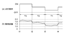
- FIG. 3 is a timing chart showing an operation example in which the lighting duty ratio is changed by changing the extinguishing time of intermittent lighting based on the signal from the distance sensor 32. Note that FIG. 3 shows a conceptual diagram, and the lighting (ON) time and the extinguishing (OFF) time are different from the times shown in Tables 1 and 2 described above.
- the control unit 16 of the ultraviolet irradiation device 100 measures the distance between the person and the light emitting surface 12 based on the signal from the distance sensor 32. Then, the period (time t1 to t2) in which a person exists within the range of the distance from the light emitting surface 12 within the range of 1.6 m-1.99 m is set as the period T3 for selecting the operation mode 3, and the operation modes in Table 2 are set. The lighting operation pattern of 3 is executed.
- the control unit 16 sets the distance from the light emitting surface 12 within the range of 1.3m-1.59m based on the signal from the distance sensor 32.
- the period (time t2 to t3) in which it is determined that a person exists is defined as the period T2 for selecting the operation mode 2. Then, during this period T2, the extinguishing time is made longer than that of the period T3 to reduce the lighting duty ratio of intermittent lighting. That is, the amount of ultraviolet rays radiated from the light source unit is reduced. Further, when a person moves within the range of 1.0 m-1.29 m, the control unit 16 has a distance of 1.0 m-1.29 m from the light emitting surface 12 based on the signal from the distance sensor 32.
- the period (time t3 to t4) in which it is determined that a person exists is defined as the period T1 for selecting the operation mode 1. Then, during this period T1, the extinguishing time is further lengthened as compared with the period T2 to reduce the lighting duty ratio of intermittent lighting. That is, the amount of ultraviolet rays radiated from the light source unit is further reduced.
- the operation pattern applied to the present invention is not limited to the above.
- the lighting duty ratio may be variably controlled by changing the lighting time.
- Table 3 shows the lighting operation in this case.
- FIG. 4 is a timing chart showing an operation example in which the lighting duty ratio is changed by changing the lighting time of intermittent lighting based on the signal from the distance sensor 32.
- FIG. 4 shows a conceptual diagram, and the lighting (ON) time and the extinguishing (OFF) time are different from the times shown in Table 3 described above.
- the control unit 16 of the ultraviolet irradiation device 100 executes the lighting operation pattern of the operation mode 3 in Table 3 during the period T3 (time t1 to t2). Then, during the period T2 (time t2 to t3), the control unit 16 shortens the lighting time as compared with the period T3 to reduce the lighting duty ratio of intermittent lighting. Further, the control unit 16 further shortens the lighting time during the period T1 (time t3 to t4) as compared with the period T2 to reduce the lighting duty ratio of intermittent lighting.
- the present invention is not limited to this, and the amount of ultraviolet rays emitted may be controlled according to a predetermined section by varying the illuminance of the ultraviolet rays on the light emitting surface 12 (Table 4).
- Table 4 the illuminance of ultraviolet rays on the light emitting surface 12
- the voltage applied to the light emitting body (excimer lamp) provided in the light source unit is adjusted, and the voltage is applied to the light emitting body (excimer lamp) provided in the light source unit.
- There are methods such as adjusting the frequency of the voltage.
- the illuminance shown in Table 4 is the illuminance of ultraviolet rays at a position, for example, 20 mm away from the light emitting surface 12 in the direction orthogonal to the light emitting surface 12.
- the illuminance shown in Table 4 is set so that the illuminance on the surface irradiated with ultraviolet rays (the surface receiving ultraviolet rays) in each section is substantially the same.
- FIG. 5 is a timing chart showing an operation example in which the amount of ultraviolet rays is changed by changing the illuminance of intermittent lighting based on the signal from the distance sensor 32.
- the lighting duty ratio of intermittent lighting is constant.
- the vertical axis of FIG. 5A shows the ON-OFF lighting operation and the illuminance on the light emitting surface 12 during the lighting (ON) time.
- FIG. 5 shows a conceptual diagram, and the illuminance value in each mode is different from the illuminance value shown in Table 4 described above.
- the control unit 16 of the ultraviolet irradiation device 100 executes the lighting operation of the operation mode 3 in Table 4 during the period T3 (time t1 to t2).
- control unit 16 sets the illuminance of the intermittent lighting to be lower than that of the period T3 during the period T2 (time t2 to t3). Further, the control unit 16 sets the illuminance of the intermittent lighting to be lower than that of the period T2 during the period T1 (time t3 to t4).
- the illuminance shown in FIG. 5 may be reduced in addition to the reduction of the lighting duty ratio shown in FIGS. 3 and 4.
- the control unit 16 of the ultraviolet irradiation device 100 changes the illuminance of the ultraviolet rays radiated from the light source unit on the light emitting surface 12 based on the signal from the distance sensor 32.
- FIG. 6 is a timing chart showing an operation example in which the amount of ultraviolet rays is changed by changing the illuminance of continuous lighting based on the signal from the distance sensor 32.
- the vertical axis of FIG. 6A shows the ON-OFF lighting operation and the illuminance on the light emitting surface 12 during the lighting (ON) time.
- the control unit 16 of the ultraviolet irradiation device 100 executes the lighting operation of the operation mode 3 during the period T3 (time t1 to t2). Then, the control unit 16 sets the illuminance of continuous lighting to be lower than that of the period T3 during the period T2 (time t2 to t3). Further, the control unit 16 sets the continuous lighting to a lower illuminance than the period T2 during the period T1 (time t3 to t4).
- a moving object enters the space by setting a predetermined distance width in the section (distance width) set by the distance from the light emitting surface 12.
- the lighting operation mode is prevented from reacting sensitively due to the movement of the moving object.
- the distance width of this section is appropriately set according to the place where it is used and the scene where it is used.
- the distance width can be appropriately changed in the range of 10 cm to 2 m.
- a pyroelectric type motion sensor is used as the detection unit 31
- the present invention is not limited to this.
- a reflector is installed at an arbitrary position (for example, a wall, a floor, a desk, etc.) in the space where the ultraviolet irradiation device 100 is arranged, and the detection unit 31 radiates light toward the reflector.
- the configuration may be such that the location of a person in the space is detected depending on whether or not the light reflected by the reflector can be detected. In this case, the detection unit 31 determines that a person exists in the space when the reflected light from the reflector cannot be detected.
- the ultraviolet irradiation device 100 may include a driving unit that changes the direction of the light emitting surface 12.
- the distance sensor 32 measures the distance from the object facing the light emitting surface 12 according to the direction of the light emitting surface 12.
- the ultraviolet irradiation device 100 includes a light source unit with a swing function, changes the swing angle in a predetermined pattern or a pattern instructed by the user, and changes the irradiation position of ultraviolet rays in a wide range. Irradiate with ultraviolet rays.
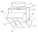
- FIG. 7 is a schematic diagram showing an example of an ultraviolet irradiation device 100 having a variable ultraviolet irradiation direction.
- the ultraviolet irradiation device 100 is supported by a support portion 112 fixed to a mounting portion 111 mounted on, for example, a ceiling or the like.
- the support portion 112 is rotatably fixed to the mounting portion 111 with the rotation shaft 113 as the center.
- the ultraviolet irradiation device 100 is rotatably supported with respect to the support portion 112 around the rotation shaft 114.
- the ultraviolet irradiation device 100 can swing up, down, left and right.
- the configuration of the ultraviolet irradiation device 100 having a swing function is not limited to the configuration shown in FIG. 7.
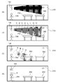
- FIG. 8A when the ultraviolet irradiation device 100 points the light emitting surface 12 (not shown in FIG. 8A) in the horizontal direction, the control unit 16 receives a signal from the distance sensor 32. Based on this, it is determined that the objects facing the light emitting surface 12 are sufficiently separated, and a relatively high amount of ultraviolet rays is emitted from the light source unit. As a result, sterilization and inactivation in the space 210 can be strongly performed.
- the ultraviolet irradiation device 100 turns the light emitting surface 12 (not shown in FIG. 8 (b)) slightly downward from the horizontal direction, the light emitting surface is determined by the distance sensor 32.
- the desk 202 is detected in the section H relatively far from 12.
- the operation mode is selected according to the distance from the light emitting surface 12 to the desk 202, and the amount of ultraviolet rays emitted from the light source unit is reduced as compared with the state shown in FIG. 8A.
- the distance sensor 32 compares the light emitting surface 12 with the light emitting surface 12.
- the desk 203 is detected in the section D close to the target. Then, the operation mode is selected according to the distance from the light emitting surface 12 to the desk 203, and the amount of ultraviolet rays emitted from the light source unit is reduced as compared with the state shown in FIG. 8 (b).
- the surface of the desk 203 may be deteriorated by the ultraviolet rays.
- the ultraviolet irradiation device 100 turns the light emitting surface 12 (not shown in FIG. 8D) downward in the vertical direction, the distance sensor 32 is used to move the light emitting surface 12 most from the light emitting surface 12.
- the operation mode corresponding to the distance from the light emitting surface 12 to the person 204 is selected, and the amount of ultraviolet rays emitted from the light source unit is set to the lowest. In this way, even when the direction of the light emitting surface 12 fluctuates, it is possible to appropriately measure the distance between the light emitting surface 12 and the object and switch to a suitable lighting operation mode for control.
- the swing angle is changed according to a predetermined pattern or a pattern instructed by the user, but the swing angle is fixed at the swing angle instructed by the user and ultraviolet irradiation is performed. May be good.
- the user can use a remote controller, a smartphone, or the like to instruct the swing angle so that the area where sterilization and inactivation are to be intensively performed is irradiated with ultraviolet rays.
- the distance between the light emitting surface 12 and the object can be appropriately measured at the swing angle instructed by the user, and the operation can be performed in an appropriate lighting operation mode.
- the magnitude of the amount of ultraviolet rays in each lighting operation mode can be determined by whether or not the "integrated amount of ultraviolet rays in a unit time" is relatively low.
- the light source unit is periodically controlled by the control unit 16
- it refers to a value obtained by dividing the integrated radiation amount of ultraviolet rays in each lighting cycle (1 cycle) by the time of the lighting cycle. ..
- the integrated radiation amount of the ultraviolet rays emitted during the lighting cycle is the sum of the lighting time and the extinguishing time.
- the value is divided by the value. That is, the "integrated amount of ultraviolet rays per unit time" corresponds to the average value of the integrated amount of radiation in each lighting cycle.
- the integrated radiation amount of ultraviolet rays within an arbitrarily set time (for example, 5 minutes, 10 minutes, etc.) is set to the above-mentioned set time (5 minutes, 10 minutes in the above example).
- the "integrated amount of ultraviolet rays per unit time” is set by the value divided by (minutes, etc.). In this case, the "integrated amount of ultraviolet rays per unit time" corresponds to the average value of the accumulated radiation amount during the continuous lighting operation.
Landscapes
- Health & Medical Sciences (AREA)
- Epidemiology (AREA)
- Life Sciences & Earth Sciences (AREA)
- Animal Behavior & Ethology (AREA)
- General Health & Medical Sciences (AREA)
- Public Health (AREA)
- Veterinary Medicine (AREA)
- Circuit Arrangement For Electric Light Sources In General (AREA)
- Apparatus For Disinfection Or Sterilisation (AREA)
- Disinfection, Sterilisation Or Deodorisation Of Air (AREA)
- Physical Or Chemical Processes And Apparatus (AREA)
Abstract
Description
ACGIH(American Conference of Governmental Industrial Hygienists:米国産業衛生専門家会議)やJIS Z 8812(有害紫外放射の測定方法)によれば、人体への1日(8時間)あたりの紫外線照射量は、波長ごとに許容限界値(TLV:Threshold Limit Value)が定められており、許容限界値を超えない程度に所定時間当たりに照射される紫外線の照度と照射量を決定することが求められている。この許容限界値は、今後は改定されてゆく可能性もあるが、何かしら紫外線照射量の上限値を定めておくことは、より安全な運用を行う上で好ましい。
また複数の点灯動作モードは、それぞれ前記光放射面からの離間距離で定められた区間に対応して定められており、点灯動作モードの切り替えは、光放射面からの離間距離で定められた区間(距離幅)から外れる場合に実行される。
これにより、所定の区間(距離幅)の範囲内に物体が存在する場合は同じ点灯動作モードを実行することで、離間距離が僅かに変動する場合に点灯動作モードの切り替えが実行されることが無い。そのため、紫外線が照射される空間中で物体が移動する環境下であっても、点灯動作モードを適切に切り替えることができ、また装置の誤動作を防ぐことができる。
これにより、光源からの離間距離の大小に応じて、照射される紫外線量を適切に制御することができる。
これにより、光源からの離間距離の大小に応じて、照射される紫外線量を適切に制御することができる。
これにより、光源からの離間距離の大小に応じて、照射される紫外線量を適切に制御することができる。
この場合、紫外線が照射される空間中で人が移動する環境下であっても、点灯動作モードを適切に切り替えることができる。また、人が光放射面に近づくにつれて光源部から放射される紫外線量が低くなるよう設定すれば、光源に対して近い距離にいる人に対して高いエネルギー量の光が照射されることを適切に抑制することができる。
この場合、微生物やウイルスの不活化を効果的に行うことができる。
これにより、紫外線が放射される向きが変動する場合においても、光放射面と物体との離間距離を適切に測定し、適した点灯動作モードに切り替え制御することができる。
また複数の点灯動作モードは、それぞれ前記光放射面からの離間距離で定められた区間に対応して定められており、点灯動作モードの切り替えは、光放射面からの離間距離で定められた区間(距離幅)から外れる場合に実行される。
これにより、所定の区間(距離幅)の範囲内に物体が存在する場合は同じ点灯動作モードを実行することで、離間距離が僅かに変動する場合に点灯動作モードの切り替えが実行されることが無い。そのため、紫外線が照射される空間中で物体が移動する環境下であっても、点灯動作モードを適切に切り替えることができ、また装置の誤動作を防ぐことができる。
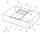
図1は、本実施形態における紫外線照射装置100の外観イメージ図である。
紫外線照射装置100は、人や動物が存在する空間内において紫外線照射を行い、当該空間や当該空間内の物体表面に存在する微生物やウイルスを不活化する装置である。
ここで、上記空間は、例えば、オフィス、商業施設、医療施設、駅施設、学校、役所、劇場、ホテル、飲食店等の施設内の空間や、自動車、電車、バス、タクシー、飛行機、船等の乗物内の空間を含む。なお、上記空間は、病室、会議室、トイレ、エレベータ内などの閉鎖された空間であってもよいし、閉鎖されていない空間であってもよい。
なお、ここでいう「不活化」とは、微生物やウイルスを死滅させる(又は感染力や毒性を失わせる)ことを指すものである。
また、紫外線照射装置100には、人の存在を検知するための検知部31と、光放射面12に対面する物体との離間距離を測定する距離センサ32とが設けられている。
筐体11内部には、紫外線光源として、エキシマランプ20が収容されている。エキシマランプ20は、例えば中心波長222nmの紫外線を放出するKrClエキシマランプとすることができる。なお、紫外線光源は、KrClエキシマランプに限定されるものではなく、190nm~235nmの波長範囲にある紫外線を放射する光源であればよい。
なお、筐体11と紫外線光源(エキシマランプ20)とで光源部を構成している。
例えば、約200nmといった短波長のUV放射線は、非常に効率良く水を通過するものの、ヒト細胞の外側部分(細胞質)による吸収が大きく、UV放射線に敏感なDNAを含む細胞核に到達するのに十分なエネルギーを有さない場合がある。そのため、上記の短波長のUV放射は、ヒト細胞に対する悪影響が少ない。一方で、波長240nmを超える紫外線は、ヒトの細胞核中のDNAにダメージを与えうる。また、波長190nm未満の紫外線は、オゾンを発生させることが知られている。
そこで、本実施形態では、紫外線光源として、人体への悪影響が少なく、不活化効果が得られる波長域190nm~235nmの紫外線を放射し、それ以外のUVCを実質的に放射しない紫外線光源を用いる。また、さらに安全性の高い波長帯域として、波長域200nm~230nmにピーク波長を有する紫外線光源を用いてもよい。
なお、発光ガスは上記に限定されない。例えば、発光ガスとして臭化クリプトン(KrBr)ガス等を用いることもできる。KrBrエキシマランプの場合、得られる放射光のピーク波長は207nmである。
また、図1では、紫外線照射装置100が複数(3本)の放電容器21を備えているが、放電容器21の数は特に限定されない。
そして、放電容器21は、これら2つの電極22、22に接触しながら跨るように配置されている。具体的には、2つの電極22、23には凹溝が形成されており、放電容器21は、電極22、23の凹溝に嵌め込まれている。
ここで、電極22、23は、エキシマランプ21から放射される光に対して反射性を有する金属部材により構成されていてもよい。この場合、放電容器21から-Z方向に放射された光を反射して+Z方向に進行させることができる。
電源部15は、電源からの電力が供給されるインバータ等の電源部材や、電源部材を冷却するためのヒートシンク等の冷却部材を含む。また、制御部16は、光源部を構成するエキシマランプ20の点灯を制御する。
距離センサ32は、例えば、赤外LEDなどの赤外線発光素子とフォトダイオードなどの受光素子とを有し、赤外線発光素子から放射され対象物によって反射された赤外線を受光素子により受光することで対象物までの距離を検知する赤外線センサとすることができる。距離センサ32は、光放射面12に対面する物体を検知している場合、検知信号を制御部16に発信する。
なお、距離センサ32は、光放射面12に対面する物体との離間距離を測定できればよく、上記の赤外線センサに限定されるものではない。
制御部16が備える複数の点灯動作モードは、光照射面12からの離間距離で定められた区間(区間A、区間B、区間C)に対応して定められ、区間毎に異なる点灯動作モードが設定されている。これにより、物体200がどの区間に存在するかによって光源部の点灯動作モードが切り替えられる。
第一の実施形態は、距離センサ32からの信号に基づき、光放射面12と物体200との離間距離を判定するものである。また光放射面12からの離間距離として4つの区間が設定され、各区間にそれぞれ異なる点灯動作モード(動作モード1~4)が設定されている。表1に具体的な点灯動作が示されている。
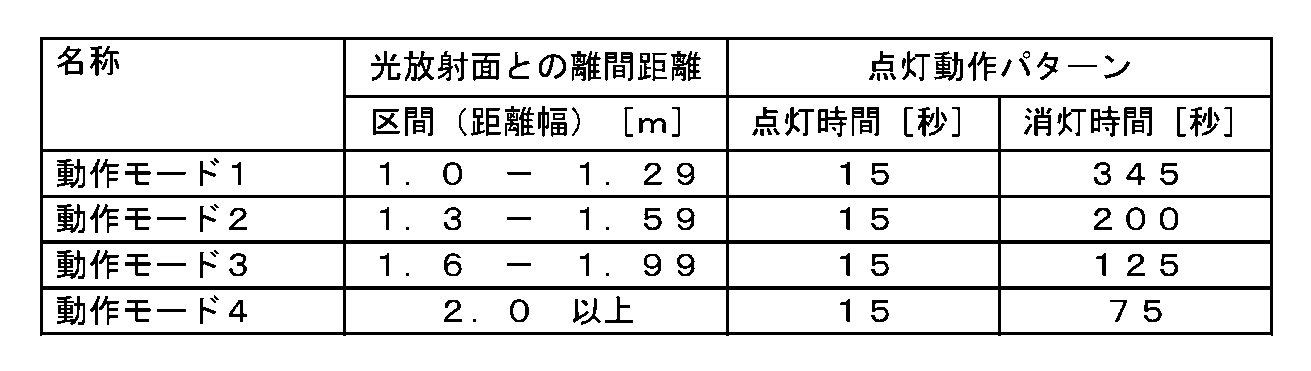
なお、光放射面12に対面する物体200が人であることも想定されるので、物体200に照射される紫外線照射量が、ACGIHの許容限界値(TLV)を超えないように点灯動作パターンを設定することが好ましい。

また人感センサ31により人の存在を検知する場合は、動作モード1~4が設定されており、各動作モード1~4は光放射面12からの離間距離に対応して定められた4つの区間にそれぞれ対応している。そして距離センサ32からの信号に基づき、所定区間に物体200が存在すると判定した場合に、その区間に対応する動作モードが選択される。例えば、光放射面12との離間距離が1.4mの場所に物体200が存在すると判定される場合は、動作モード2が選択され、15秒点灯-200秒消灯の点灯動作パターンが実行される。また物体200が離間距離1.2mの場所に存在すると判定される場合は、動作モード1に切り替え制御され、15秒点灯-345秒消灯の点灯動作パターンが実行される。
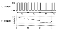
図3は、距離センサ32からの信号に基づき、間欠点灯の消灯時間を変更することで点灯デューティ比を変更する場合の動作例を示すタイミングチャートである。なお、図3は概念図を示しており、点灯(ON)時間および消灯(OFF)時間は上述した表1や表2に示す時間とは異なる。
そして、光放射面12との離間距離が1.6m-1.99mの範囲内に人が存在する期間(時刻t1~t2)を、動作モード3を選択する期間T3とし、表2の動作モード3の点灯動作パターンを実行する。
人が1.3m-1.59mの範囲内に移動すると、制御部16は、距離センサ32からの信号に基づき、光放射面12との離間距離が1.3m-1.59mの範囲内に人が存在すると判定している期間(時刻t2~t3)を、動作モード2を選択する期間T2とする。そして、この期間T2の間は、期間T3よりも消灯時間を長くして間欠点灯の点灯デューティ比を低減させる。つまり、光源部から放射される紫外線量を低くする。
また、人が1.0m-1.29mの範囲内に移動すると、制御部16は、距離センサ32からの信号に基づき、光放射面12との離間距離が1.0m-1.29mの範囲内に人が存在すると判定している期間(時刻t3~t4)を、動作モード1を選択する期間T1とする。そして、この期間T1の間は、期間T2よりもさらに消灯時間を長くして間欠点灯の点灯デューティ比を低減させる。つまり、光源部から放射される紫外線量をさらに低くする。
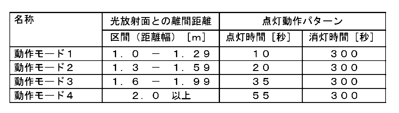
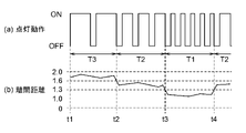
この場合、紫外線照射装置100の制御部16は、期間T3(時刻t1~t2)においては、表3の動作モード3の点灯動作パターンを実行する。そして、制御部16は、期間T2の間(時刻t2~t3)は、期間T3よりも点灯時間を短くして間欠点灯の点灯デューティ比を低減させる。さらに、制御部16は、期間T1の間(時刻t3~t4)は、期間T2よりもさらに点灯時間を短くして間欠点灯の点灯デューティ比を低減させる。
またこれに限らず、光放射面12における紫外線の照度を可変させることによって、所定の区間に応じて放射される紫外線量を制御するものであってもよい(表4)。光放射面12における紫外線の照度を可変させる方法としては、光源部に設けられた発光体(エキシマランプ)への印加電圧を調整する、光源部に設けられた発光体(エキシマランプ)への印加電圧の周波数を調整する、などの方法がある。
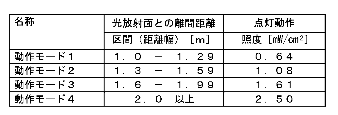
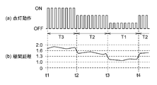
この場合、紫外線照射装置100の制御部16は、期間T3(時刻t1~t2)においては、表4の動作モード3の点灯動作を実行する。そして、制御部16は、期間T2の間(時刻t2~t3)は、期間T3よりも間欠点灯を低照度とする。さらに、制御部16は、期間T1の間(時刻t3~t4)は、期間T2よりもさらに間欠点灯を低照度とする。
また、上記においては、光源部による紫外線照射方式が間欠点灯方式である場合について説明したが、光源部による紫外線照射が連続的に行われる連続点灯方式を適用することもできる。この場合、紫外線照射装置100の制御部16は、距離センサ32からの信号に基づき、光源部から放射される紫外線の光放射面12での照度を変更する。
この場合、紫外線照射装置100の制御部16は、期間T3(時刻t1~t2)においては、動作モード3の点灯動作を実行する。そして、制御部16は、期間T2の間(時刻t2~t3)は、期間T3よりも連続点灯を低照度とする。さらに、制御部16は、期間T1の間(時刻t3~t4)は、期間T2よりもさらに連続点灯を低照度とする。
例えば、紫外線照射装置100が配置された空間内の任意の位置(例えば、壁、床、机など)に反射板を設置しておき、検知部31は、反射板に向けて光を放射し、当該反射板により反射された光を検出できたか否かによって、当該空間内の人の所在を検知する構成であってもよい。この場合、検知部31は、反射板からの反射光が検出できない場合に、当該空間内に人が存在すると判定する。
例えば、紫外線照射装置100は、首振り機能付きの光源部を備え、予め決められたパターンで、もしくは、ユーザにより指示されたパターンで首振り角度を変化させ、紫外線の照射位置を変えながら広範囲に紫外線を照射する。
この図7に示すように、紫外線照射装置100は、例えば天井等に取り付けられる取付部111に固定された支持部112によって支持される。ここで、支持部112は、回転軸113を中心として、取付部111に対して回動可能に固定されている。また、紫外線照射装置100は、回転軸114を中心として、支持部112に対して回動可能に支持されている。
このような構成により、紫外線照射装置100は、上下左右に首振りを行うことが可能である。なお、首振り機能を有する紫外線照射装置100の構成は、図7に示す構成に限定されない。
紫外線照射装置100は、壁201により区画された空間210内に設置されており、空間210内には、机202、203が配置され、人204が存在するものとする。
図8(a)に示すように、紫外線照射装置100が光放射面12(図8(a)では不図示)を水平方向に向けている場合、制御部16は、距離センサ32からの信号に基づき、光放射面12に対面する物体が十分に離れていると判定し、光源部から比較的高い紫外線量の紫外線を放射する。これにより、空間210内の殺菌、不活化を強力に行うことができる。
その後、図8(c)に示すように、紫外線照射装置100が光放射面12(図8(c)では不図示)をさらに下方向に向けると、距離センサ32によって、光放射面12から比較的近い区間Dにおいて机203が検知される。すると、光放射面12から机203までの距離に応じた動作モードが選択され、図8(b)に示す状態よりも光源部から放射される紫外線量が低減される。
その後、図8(d)に示すように、紫外線照射装置100が光放射面12(図8(d)では不図示)を鉛直方向下向きに向けると、距離センサ32によって、光放射面12から最も近い区間Aにおいて人204が検知される。すると、光放射面12から人204までの距離に応じた動作モードが選択され、光源部から放射される紫外線量が最も低く設定される。
このように、光放射面12の向きが変動する場合においても、光放射面12と物体との離間距離を適切に測定し、適した点灯動作モードに切り替え制御することができる。
Claims (8)
- 波長帯域が190nm~235nmの紫外線を放射する光放射面を備えた光源部と、
前記光源部の点灯を制御する制御部と、
前記光放射面に対面する物体との離間距離を測定する距離センサと、を備え、
前記制御部は、
複数の点灯動作モードを備え、前記複数の点灯動作モードは、それぞれ前記光放射面からの離間距離で定められた区間に対応して定められ、前記複数の点灯動作モードは、前記光源部から放射される紫外線量がそれぞれ異なるよう設定されており、
前記距離センサからの信号に基づき、前記点灯動作モードを切り替え制御することを特徴とする紫外線照射装置。 - 前記複数の点灯動作モードは、前記光放射面からの離間距離が相対的に近い区間になると、
前記光源部から放射される紫外線量が低くなるよう設定されていることを特徴とする請求項1に記載の紫外線照射装置。 - 前記複数の点灯動作モードは、前記光放射面からの離間距離が相対的に近い区間になると、
前記光源部から放射される紫外線の前記光放射面における照度が低くなるよう設定されていることを特徴とする請求項2に記載の紫外線照射装置。 - 前記複数の点灯動作モードは、前記光放射面からの離間距離が相対的に近い区間になると、
前記光源部の点灯デューティ比を低減するように、前記光源部の点灯を制御することを特徴とする請求項2に記載の紫外線照射装置。 - 前記光放射面に対面する人の所在を検知する人感センサをさらに備え、
前記制御部は、
前記人感センサにより人の所在を検知している場合に、前記距離センサからの信号に基づき、前記点灯動作モードを切り替え制御することを特徴とする請求項1から4のいずれか1項に記載の紫外線照射装置。 - 前記制御部は、
前記人感センサにより人の所在を検知していない場合、前記人感センサにより人の所在を検知している場合と比較して、前記光源部から放射される紫外線量が高くなるよう設定されていることを特徴とする請求項5に記載の紫外線照射装置。 - 前記光放射面の向きを変動させる駆動部を備え、
前記距離センサは、前記光放射面の向きに対応して、前記光放射面に対面する物体との離間距離を測定することを特徴とする請求項1~4のいずれか1項に記載の紫外線照射装置。
- 波長帯域が190nm~235nmの紫外線を放射する光放射面を有する光源部の点灯を制御する紫外線照射方法であって、
前記光放射面に対面する物体との離間距離を測定する距離センサからの信号を受信するステップと、
それぞれ前記光放射面からの離間距離で定められた区間に対応して定められるとともに、前記光源部から放射される紫外線量がそれぞれ異なるよう設定された複数の点灯動作モードを、前記距離センサからの信号に基づいて切り替えて、前記光源部の点灯を制御するステップと、を含むことを特徴とする紫外線照射方法。
Priority Applications (3)
| Application Number | Priority Date | Filing Date | Title |
|---|---|---|---|
| EP21900430.6A EP4238585A4 (en) | 2020-12-01 | 2021-11-19 | ULTRAVIOLET IRRADIATION DEVICE AND ULTRAVIOLET IRRADIATION METHOD |
| US18/037,068 US20240024524A1 (en) | 2020-12-01 | 2021-11-19 | Ultraviolet light irradiation device and ultraviolet light irradiation method |
| CN202180075758.XA CN116528915A (zh) | 2020-12-01 | 2021-11-19 | 紫外线照射装置及紫外线照射方法 |
Applications Claiming Priority (4)
| Application Number | Priority Date | Filing Date | Title |
|---|---|---|---|
| JP2020199935 | 2020-12-01 | ||
| JP2020-199935 | 2020-12-01 | ||
| JP2021-004239 | 2021-01-14 | ||
| JP2021004239A JP6977898B1 (ja) | 2020-12-01 | 2021-01-14 | 紫外線照射装置および紫外線照射方法 |
Publications (1)
| Publication Number | Publication Date |
|---|---|
| WO2022118675A1 true WO2022118675A1 (ja) | 2022-06-09 |
Family
ID=78815531
Family Applications (1)
| Application Number | Title | Priority Date | Filing Date |
|---|---|---|---|
| PCT/JP2021/042536 Ceased WO2022118675A1 (ja) | 2020-12-01 | 2021-11-19 | 紫外線照射装置および紫外線照射方法 |
Country Status (5)
| Country | Link |
|---|---|
| US (1) | US20240024524A1 (ja) |
| EP (1) | EP4238585A4 (ja) |
| JP (1) | JP6977898B1 (ja) |
| CN (1) | CN116528915A (ja) |
| WO (1) | WO2022118675A1 (ja) |
Cited By (1)
| Publication number | Priority date | Publication date | Assignee | Title |
|---|---|---|---|---|
| WO2023099161A1 (en) * | 2021-11-30 | 2023-06-08 | Ams-Osram International Gmbh | Method for operating a radiation emitting device |
Families Citing this family (3)
| Publication number | Priority date | Publication date | Assignee | Title |
|---|---|---|---|---|
| JP7181483B2 (ja) * | 2021-03-31 | 2022-12-01 | ダイキン工業株式会社 | 紫外線照射装置 |
| US20230398244A1 (en) * | 2022-06-08 | 2023-12-14 | B/E Aerospace | Proximity based ultraviolet dosage control |
| WO2025179375A2 (en) * | 2025-02-24 | 2025-09-04 | Uvx Inc. | Sealed high-voltage ultraviolet light sanitizer |
Citations (6)
| Publication number | Priority date | Publication date | Assignee | Title |
|---|---|---|---|---|
| WO2016061303A1 (en) * | 2014-10-15 | 2016-04-21 | Sensor Electronic Technology, Inc. | Ultraviolet-based detection and sterilization |
| JP6025756B2 (ja) | 2011-03-07 | 2016-11-16 | ザ トラスティーズ オブ コロンビア ユニバーシティ イン ザ シティ オブ ニューヨーク | 殺菌装置、及び、殺菌装置の作動方法 |
| JP2018517488A (ja) * | 2015-06-03 | 2018-07-05 | ザ トラスティーズ オブ コロンビア ユニバーシティ イン ザ シティ オブ ニューヨーク | 選択的にウイルスに影響を及ぼすかおよび/またはそれを死滅させるための装置、方法およびシステム |
| WO2018131582A1 (ja) * | 2017-01-10 | 2018-07-19 | ウシオ電機株式会社 | 紫外線殺菌装置 |
| WO2019164810A1 (en) * | 2018-02-20 | 2019-08-29 | Freestyle Partners, LLC | Portable and disposable far-uvc device |
| WO2019186880A1 (ja) * | 2018-03-29 | 2019-10-03 | サンエナジー株式会社 | 紫外線照射装置、紫外線照射方法、照明装置および紫外線照射システム |
Family Cites Families (3)
| Publication number | Priority date | Publication date | Assignee | Title |
|---|---|---|---|---|
| KR101298733B1 (ko) * | 2012-12-04 | 2013-08-21 | (주)대영인테리어 | 싱크대 살균장치 |
| US9095633B1 (en) * | 2014-10-30 | 2015-08-04 | Daylight Medical | Object decontamination apparatus with an adjustable ultraviolet source |
| WO2018124713A1 (ko) * | 2016-12-29 | 2018-07-05 | 서울바이오시스주식회사 | 포충기 |
-
2021
- 2021-01-14 JP JP2021004239A patent/JP6977898B1/ja active Active
- 2021-11-19 US US18/037,068 patent/US20240024524A1/en active Pending
- 2021-11-19 WO PCT/JP2021/042536 patent/WO2022118675A1/ja not_active Ceased
- 2021-11-19 EP EP21900430.6A patent/EP4238585A4/en not_active Withdrawn
- 2021-11-19 CN CN202180075758.XA patent/CN116528915A/zh not_active Withdrawn
Patent Citations (6)
| Publication number | Priority date | Publication date | Assignee | Title |
|---|---|---|---|---|
| JP6025756B2 (ja) | 2011-03-07 | 2016-11-16 | ザ トラスティーズ オブ コロンビア ユニバーシティ イン ザ シティ オブ ニューヨーク | 殺菌装置、及び、殺菌装置の作動方法 |
| WO2016061303A1 (en) * | 2014-10-15 | 2016-04-21 | Sensor Electronic Technology, Inc. | Ultraviolet-based detection and sterilization |
| JP2018517488A (ja) * | 2015-06-03 | 2018-07-05 | ザ トラスティーズ オブ コロンビア ユニバーシティ イン ザ シティ オブ ニューヨーク | 選択的にウイルスに影響を及ぼすかおよび/またはそれを死滅させるための装置、方法およびシステム |
| WO2018131582A1 (ja) * | 2017-01-10 | 2018-07-19 | ウシオ電機株式会社 | 紫外線殺菌装置 |
| WO2019164810A1 (en) * | 2018-02-20 | 2019-08-29 | Freestyle Partners, LLC | Portable and disposable far-uvc device |
| WO2019186880A1 (ja) * | 2018-03-29 | 2019-10-03 | サンエナジー株式会社 | 紫外線照射装置、紫外線照射方法、照明装置および紫外線照射システム |
Non-Patent Citations (1)
| Title |
|---|
| See also references of EP4238585A4 |
Cited By (1)
| Publication number | Priority date | Publication date | Assignee | Title |
|---|---|---|---|---|
| WO2023099161A1 (en) * | 2021-11-30 | 2023-06-08 | Ams-Osram International Gmbh | Method for operating a radiation emitting device |
Also Published As
| Publication number | Publication date |
|---|---|
| US20240024524A1 (en) | 2024-01-25 |
| JP6977898B1 (ja) | 2021-12-08 |
| CN116528915A (zh) | 2023-08-01 |
| EP4238585A4 (en) | 2024-05-22 |
| EP4238585A1 (en) | 2023-09-06 |
| JP2022087780A (ja) | 2022-06-13 |
Similar Documents
| Publication | Publication Date | Title |
|---|---|---|
| JP6977898B1 (ja) | 紫外線照射装置および紫外線照射方法 | |
| US20230414805A1 (en) | Inactivation method and inactivation system | |
| US20230302172A1 (en) | Inactivation device | |
| JP2021029502A (ja) | 殺菌装置および室内殺菌システム | |
| JP6897853B1 (ja) | 不活化装置および不活化方法 | |
| WO2022234813A1 (ja) | 紫外線照射装置および紫外線照射方法 | |
| US20220241444A1 (en) | Inactivation apparatus and inactivation method | |
| US20230248860A1 (en) | Inactivation device for bacteria and/or viruses and method of inactivation treatment for bacteria and/or viruses | |
| JP6977899B1 (ja) | 紫外線照射装置および紫外線照射方法 | |
| JP6973603B1 (ja) | 紫外線照射装置および紫外線照射方法 | |
| JP6977903B1 (ja) | 不活化装置および不活化方法 | |
| JP6912014B1 (ja) | 不活化方法および不活化システム | |
| JP2022043880A (ja) | スポットライト型光源、及びスポットライト型照明用光源 | |
| JP6885504B1 (ja) | 不活化装置および不活化方法 | |
| JP7099595B2 (ja) | 不活化装置 | |
| JP7537319B2 (ja) | 不活化装置および不活化方法 | |
| JP7095786B2 (ja) | 不活化装置 | |
| JP2022054721A (ja) | 紫外線照射装置 | |
| JP2022134282A (ja) | 不活化装置および不活化方法 | |
| JP2023119620A (ja) | 不活化処理方法、不活化処理システム |
Legal Events
| Date | Code | Title | Description |
|---|---|---|---|
| 121 | Ep: the epo has been informed by wipo that ep was designated in this application |
Ref document number: 21900430 Country of ref document: EP Kind code of ref document: A1 |
|
| WWE | Wipo information: entry into national phase |
Ref document number: 202180075758.X Country of ref document: CN |
|
| WWE | Wipo information: entry into national phase |
Ref document number: 18037068 Country of ref document: US |
|
| ENP | Entry into the national phase |
Ref document number: 2021900430 Country of ref document: EP Effective date: 20230601 |
|
| NENP | Non-entry into the national phase |
Ref country code: DE |