WO2022123736A1 - 冷凍サイクル装置 - Google Patents
冷凍サイクル装置 Download PDFInfo
- Publication number
- WO2022123736A1 WO2022123736A1 PCT/JP2020/046094 JP2020046094W WO2022123736A1 WO 2022123736 A1 WO2022123736 A1 WO 2022123736A1 JP 2020046094 W JP2020046094 W JP 2020046094W WO 2022123736 A1 WO2022123736 A1 WO 2022123736A1
- Authority
- WO
- WIPO (PCT)
- Prior art keywords
- refrigerant
- pipe
- control device
- gas
- solenoid valve
- Prior art date
- Legal status (The legal status is an assumption and is not a legal conclusion. Google has not performed a legal analysis and makes no representation as to the accuracy of the status listed.)
- Ceased
Links
Images


Classifications
-
- F—MECHANICAL ENGINEERING; LIGHTING; HEATING; WEAPONS; BLASTING
- F25—REFRIGERATION OR COOLING; COMBINED HEATING AND REFRIGERATION SYSTEMS; HEAT PUMP SYSTEMS; MANUFACTURE OR STORAGE OF ICE; LIQUEFACTION SOLIDIFICATION OF GASES
- F25B—REFRIGERATION MACHINES, PLANTS OR SYSTEMS; COMBINED HEATING AND REFRIGERATION SYSTEMS; HEAT PUMP SYSTEMS
- F25B41/00—Fluid-circulation arrangements
- F25B41/30—Expansion means; Dispositions thereof
- F25B41/39—Dispositions with two or more expansion means arranged in series, i.e. multi-stage expansion, on a refrigerant line leading to the same evaporator
-
- F—MECHANICAL ENGINEERING; LIGHTING; HEATING; WEAPONS; BLASTING
- F25—REFRIGERATION OR COOLING; COMBINED HEATING AND REFRIGERATION SYSTEMS; HEAT PUMP SYSTEMS; MANUFACTURE OR STORAGE OF ICE; LIQUEFACTION SOLIDIFICATION OF GASES
- F25B—REFRIGERATION MACHINES, PLANTS OR SYSTEMS; COMBINED HEATING AND REFRIGERATION SYSTEMS; HEAT PUMP SYSTEMS
- F25B31/00—Compressor arrangements
- F25B31/006—Cooling of compressor or motor
- F25B31/008—Cooling of compressor or motor by injecting a liquid
-
- F—MECHANICAL ENGINEERING; LIGHTING; HEATING; WEAPONS; BLASTING
- F25—REFRIGERATION OR COOLING; COMBINED HEATING AND REFRIGERATION SYSTEMS; HEAT PUMP SYSTEMS; MANUFACTURE OR STORAGE OF ICE; LIQUEFACTION SOLIDIFICATION OF GASES
- F25B—REFRIGERATION MACHINES, PLANTS OR SYSTEMS; COMBINED HEATING AND REFRIGERATION SYSTEMS; HEAT PUMP SYSTEMS
- F25B41/00—Fluid-circulation arrangements
-
- F—MECHANICAL ENGINEERING; LIGHTING; HEATING; WEAPONS; BLASTING
- F25—REFRIGERATION OR COOLING; COMBINED HEATING AND REFRIGERATION SYSTEMS; HEAT PUMP SYSTEMS; MANUFACTURE OR STORAGE OF ICE; LIQUEFACTION SOLIDIFICATION OF GASES
- F25B—REFRIGERATION MACHINES, PLANTS OR SYSTEMS; COMBINED HEATING AND REFRIGERATION SYSTEMS; HEAT PUMP SYSTEMS
- F25B49/00—Arrangement or mounting of control or safety devices
- F25B49/02—Arrangement or mounting of control or safety devices for compression type machines, plants or systems
-
- F—MECHANICAL ENGINEERING; LIGHTING; HEATING; WEAPONS; BLASTING
- F25—REFRIGERATION OR COOLING; COMBINED HEATING AND REFRIGERATION SYSTEMS; HEAT PUMP SYSTEMS; MANUFACTURE OR STORAGE OF ICE; LIQUEFACTION SOLIDIFICATION OF GASES
- F25B—REFRIGERATION MACHINES, PLANTS OR SYSTEMS; COMBINED HEATING AND REFRIGERATION SYSTEMS; HEAT PUMP SYSTEMS
- F25B2400/00—General features or devices for refrigeration machines, plants or systems, combined heating and refrigeration systems or heat-pump systems, i.e. not limited to a particular subgroup of F25B
- F25B2400/13—Economisers
-
- F—MECHANICAL ENGINEERING; LIGHTING; HEATING; WEAPONS; BLASTING
- F25—REFRIGERATION OR COOLING; COMBINED HEATING AND REFRIGERATION SYSTEMS; HEAT PUMP SYSTEMS; MANUFACTURE OR STORAGE OF ICE; LIQUEFACTION SOLIDIFICATION OF GASES
- F25B—REFRIGERATION MACHINES, PLANTS OR SYSTEMS; COMBINED HEATING AND REFRIGERATION SYSTEMS; HEAT PUMP SYSTEMS
- F25B2400/00—General features or devices for refrigeration machines, plants or systems, combined heating and refrigeration systems or heat-pump systems, i.e. not limited to a particular subgroup of F25B
- F25B2400/23—Separators
-
- F—MECHANICAL ENGINEERING; LIGHTING; HEATING; WEAPONS; BLASTING
- F25—REFRIGERATION OR COOLING; COMBINED HEATING AND REFRIGERATION SYSTEMS; HEAT PUMP SYSTEMS; MANUFACTURE OR STORAGE OF ICE; LIQUEFACTION SOLIDIFICATION OF GASES
- F25B—REFRIGERATION MACHINES, PLANTS OR SYSTEMS; COMBINED HEATING AND REFRIGERATION SYSTEMS; HEAT PUMP SYSTEMS
- F25B2600/00—Control issues
- F25B2600/05—Refrigerant levels
-
- F—MECHANICAL ENGINEERING; LIGHTING; HEATING; WEAPONS; BLASTING
- F25—REFRIGERATION OR COOLING; COMBINED HEATING AND REFRIGERATION SYSTEMS; HEAT PUMP SYSTEMS; MANUFACTURE OR STORAGE OF ICE; LIQUEFACTION SOLIDIFICATION OF GASES
- F25B—REFRIGERATION MACHINES, PLANTS OR SYSTEMS; COMBINED HEATING AND REFRIGERATION SYSTEMS; HEAT PUMP SYSTEMS
- F25B2600/00—Control issues
- F25B2600/25—Control of valves
- F25B2600/2509—Economiser valves
-
- F—MECHANICAL ENGINEERING; LIGHTING; HEATING; WEAPONS; BLASTING
- F25—REFRIGERATION OR COOLING; COMBINED HEATING AND REFRIGERATION SYSTEMS; HEAT PUMP SYSTEMS; MANUFACTURE OR STORAGE OF ICE; LIQUEFACTION SOLIDIFICATION OF GASES
- F25B—REFRIGERATION MACHINES, PLANTS OR SYSTEMS; COMBINED HEATING AND REFRIGERATION SYSTEMS; HEAT PUMP SYSTEMS
- F25B2600/00—Control issues
- F25B2600/25—Control of valves
- F25B2600/2513—Expansion valves
-
- F—MECHANICAL ENGINEERING; LIGHTING; HEATING; WEAPONS; BLASTING
- F25—REFRIGERATION OR COOLING; COMBINED HEATING AND REFRIGERATION SYSTEMS; HEAT PUMP SYSTEMS; MANUFACTURE OR STORAGE OF ICE; LIQUEFACTION SOLIDIFICATION OF GASES
- F25B—REFRIGERATION MACHINES, PLANTS OR SYSTEMS; COMBINED HEATING AND REFRIGERATION SYSTEMS; HEAT PUMP SYSTEMS
- F25B2700/00—Sensing or detecting of parameters; Sensors therefor
- F25B2700/19—Pressures
- F25B2700/193—Pressures of the compressor
- F25B2700/1931—Discharge pressures
-
- F—MECHANICAL ENGINEERING; LIGHTING; HEATING; WEAPONS; BLASTING
- F25—REFRIGERATION OR COOLING; COMBINED HEATING AND REFRIGERATION SYSTEMS; HEAT PUMP SYSTEMS; MANUFACTURE OR STORAGE OF ICE; LIQUEFACTION SOLIDIFICATION OF GASES
- F25B—REFRIGERATION MACHINES, PLANTS OR SYSTEMS; COMBINED HEATING AND REFRIGERATION SYSTEMS; HEAT PUMP SYSTEMS
- F25B2700/00—Sensing or detecting of parameters; Sensors therefor
- F25B2700/21—Temperatures
- F25B2700/2116—Temperatures of a condenser
- F25B2700/21163—Temperatures of a condenser of the refrigerant at the outlet of the condenser
Definitions
- This disclosure relates to a refrigeration cycle device.
- an intermediate injection type refrigeration cycle device for the purpose of reducing power consumption and improving capacity of the refrigeration cycle.
- This refrigeration cycle device divides a part of the refrigerant circulating in the main circuit into the injection circuit and injects it into the intermediate pressure portion of the compressor.
- Patent Document 1 provides a gas-liquid separator in an injection circuit, and freezes a flow having a large amount of gas phase and a flow having a large amount of liquid phase in the first and second injection paths, respectively. Cycle devices are disclosed. As a result, the mass flow rate of the refrigerant flowing through the second injection path increases.
- the amount of refrigerant in the main circuit is adjusted by storing excess liquid refrigerant in the receiver tank provided in the main circuit. Since a receiver tank is provided in addition to the gas-liquid separator as a member for storing the refrigerant, the refrigeration cycle device becomes large.
- the present disclosure has been made to solve the above problems, and an object thereof is to provide an intermediate injection type refrigeration cycle apparatus capable of miniaturization.
- the refrigerating cycle device of one aspect of the present disclosure is a main circuit in which the refrigerant circulates in the order of a compressor, a condenser, a decompression device, and an evaporator, and a part of the refrigerant flowing from the condenser to the decompression device is divided into a compressor. It is equipped with an injection circuit for inflow.
- the injection circuit includes a gas-liquid separator that separates a part of the refrigerant into gas-liquid.
- the injection circuit merges the first pipe that discharges the liquid refrigerant from the gas-liquid separator, the second pipe that discharges the gas refrigerant from the gas-liquid separator, and the refrigerant that flows through the first pipe and the refrigerant that flows through the second pipe. It includes a third pipe that is allowed to flow into the injection port of the compressor. Further, the injection circuit includes a flow rate adjusting valve provided in the first pipe and a first solenoid valve provided in the second pipe. The refrigeration cycle device further includes a control device that adjusts the amount of refrigerant in the main circuit by controlling the opening degree of the flow rate adjusting valve and the open / closed state of the first solenoid valve.
- the amount of refrigerant in the main circuit is adjusted by using the gas-liquid separator provided in the injection circuit.
- the gas-liquid separator provided in the injection circuit.
- FIG. It is a figure which shows the internal structure of the refrigerating cycle apparatus which concerns on Embodiment 1.
- FIG. It is a figure which shows the structure of the gas-liquid separator schematically. It is a flowchart which shows an example of the processing flow of the control apparatus which concerns on Embodiment 1.
- FIG. It is a figure which shows the internal structure of the refrigerating cycle apparatus which concerns on Embodiment 2. It is a flowchart which shows an example of the processing flow of the control apparatus which concerns on Embodiment 2.
- FIG. It is a figure which shows an example of the internal structure of the refrigerating cycle apparatus which concerns on Embodiment 3.
- FIG. It is a flowchart which shows an example of the processing flow of the control apparatus which concerns on Embodiment 3.
- FIG. It is a flowchart which shows an example of the processing flow of the control apparatus which concerns on Embodiment 3.
- FIG. 1 It is a figure which shows an example of the internal structure of the refrigerating cycle apparatus which concerns on Embodiment 4.
- FIG. It is a figure which shows an example of the correspondence table stored in the control apparatus which concerns on Embodiment 4.
- FIG. It is a figure which shows an example of the height range set with respect to the gas-liquid separator in Embodiment 4.
- FIG. It is a figure which shows the state of a gas-liquid separator when a liquid level reaches a reference height.
- It is a flowchart which shows the flow of steps S31 to S37 among the processing of the control apparatus which concerns on Embodiment 4.
- FIG. It is a flowchart which shows the flow of steps S38-S44 among the processing of the control apparatus which concerns on Embodiment 4.
- FIG. It is a flowchart which shows the flow of steps S45 to S47 in the process of the control apparatus which concerns on Embodiment 4.
- FIG. It is a figure which shows an example of the internal structure of the refrigerating cycle apparatus which concerns on Embodiment 5. It is a figure which shows an example of the correspondence table stored in the control apparatus which concerns on Embodiment 5. It is a figure which shows an example of the height range set with respect to the gas-liquid separator in Embodiment 5. It is a flowchart which shows the flow of steps S51-S59 in the process of the control apparatus which concerns on Embodiment 5. It is a flowchart which shows the flow of steps S60 to S66 among the processing of the control apparatus which concerns on Embodiment 5.
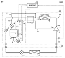
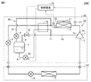
- FIG. 1 is a diagram showing an internal configuration of the refrigeration cycle apparatus 100 according to the first embodiment.
- the refrigerating cycle device 100 shown in FIG. 1 cools a cooling target space such as a room, a warehouse, a showcase, or a refrigerator.
- the refrigeration cycle device 100 includes a heat source side unit 80 and a user side unit 90.
- the heat source side unit 80 and the user side unit 90 are connected by a liquid pipe 91 and a gas pipe 92.
- a supercooled liquid refrigerant flows from the heat source side unit 80 toward the user side unit 90 in the liquid pipe 91.
- a gas refrigerant flows from the user-side unit 90 toward the heat source-side unit 80 in the gas pipe 92.
- the lengths of the liquid pipe 91 and the gas pipe 92 are adjusted according to the installation positions of the heat source side unit 80 and the user side unit 90. In the example shown in FIG. 1, one heat source side unit 80 and one user side unit 90 are shown, but the number of these units is not limited. At least one of the heat source side unit 80 and the user side unit 90 may be two or more.
- the refrigeration cycle device 100 separates a part of the refrigerant flowing from the condenser 2 to the decompression device 3 and a main circuit 50 in which the refrigerant circulates in the order of the compressor 1, the condenser 2, the decompression devices 3 and 4, and the evaporator 5. It is provided with an injection circuit 60 for flowing into the compressor 1.
- the compressor 1, the condenser 2, the decompression device 3, and the injection circuit 60 are provided in the heat source side unit 80.
- the decompression device 4 and the evaporator 5 are provided in the user-side unit 90.
- the refrigerant is, for example, a CO 2 refrigerant.
- the compressor 1 is, for example, a scroll compressor, and has a suction port 1i and a discharge port 1o.
- the compressor 1 compresses the refrigerant sucked from the suction port 1i and discharges it from the discharge port 1o.
- the compressor 1 is a positive displacement compressor driven by a drive motor (not shown) controlled by an inverter, and has a variable operating capacity. Further, the compressor 1 has an injection port 1p leading to an intermediate pressure portion of the compression chamber.
- the condenser 2 is connected to the discharge port 1o of the compressor 1 via a pipe, and condenses the refrigerant discharged from the compressor 1.
- the condenser 2 exchanges heat between the refrigerant discharged from the compressor 1 and the outside air sent by the fan 17. As a result, the heat of the refrigerant is dissipated to the outside air, and the refrigerant is cooled.
- the condenser 2 is, for example, a fin-and-tube heat exchanger having a heat transfer tube and a plurality of fins.
- the pressure reducing devices 3 and 4 are composed of an electronic expansion valve, a temperature type expansion valve, and the like, and reduce the pressure of the refrigerant that has passed through the condenser 2. Specifically, the decompression devices 3 and 4 decompress and expand the refrigerant, and adjust the flow rate of the refrigerant flowing through the main circuit 50.
- the evaporator 5 heat-exchanges the refrigerant decompressed and expanded by the depressurizing devices 3 and 4 with the air in the user-side unit 90 to evaporate the refrigerant.
- the evaporator 5 is, for example, a fin-and-tube heat exchanger having a heat transfer tube and a plurality of fins.
- the injection circuit 60 includes pipes 8, 9, 10 and 16, flow rate adjusting valves 6 and 13, a gas-liquid separator 7, and a solenoid valve 14.
- the pipe 16 connects the branch point 15 between the condenser 2 and the decompression device 3 in the main circuit 50 and the gas-liquid separator 7.
- the pipe 16 divides a part of the refrigerant flowing from the condenser 2 to the decompression device 3 and flows it into the gas-liquid separator 7.
- the flow rate adjusting valve 6 is provided in the pipe 16 and adjusts the amount of the refrigerant flowing through the injection circuit 60.
- the flow rate adjusting valve 6 is, for example, an electronic expansion valve, and the opening degree is controlled by a control device 70 described later to adjust the flow rate of the refrigerant branched to the injection circuit 60.
- the opening degree of the flow rate adjusting valve 6 is controlled to increase as the discharge temperature, which is the temperature of the refrigerant discharged from the compressor 1, increases, and decreases as the discharge temperature decreases.
- the gas-liquid separator 7 separates the refrigerant that has passed through the flow rate adjusting valve 6 into a liquid refrigerant (hereinafter referred to as “liquid refrigerant”) and a gaseous refrigerant (hereinafter referred to as “gas refrigerant”). ..
- the pipe 8 is provided to discharge the liquid refrigerant from the gas / liquid separator 7.
- the pipe 9 is provided to discharge the gas refrigerant from the gas-liquid separator 7.
- the pipe 10 merges the refrigerant flowing through the pipe 8 and the refrigerant flowing through the pipe 9 and flows them into the injection port 1p of the compressor 1. That is, the pipe 10 connects the confluence 11 of the pipes 8 and 9 with the injection port 1p.
- the pipe 8 connects the liquid refrigerant discharge port of the gas-liquid separator 7 and the confluence point 11.
- the pipe 9 connects the gas refrigerant discharge port of the gas-liquid separator 7 and the confluence point 11.
- the flow rate adjusting valve 13 is provided in the pipe 8 and adjusts the flow rate of the refrigerant in the pipe 8.
- the opening degree of the flow rate adjusting valve 13 can be changed and is controlled to a designated opening degree among a plurality of stages.
- the minimum opening is the closed state.
- the solenoid valve 14 is provided in the pipe 9 and is controlled to either an open state or a closed state.
- the refrigeration cycle device 100 includes an economizer 12, a pressure sensor 31, a temperature sensor 32, and a control device 70.
- the economizer 12 exchanges heat between the refrigerant flowing through the pipe 10 and the refrigerant flowing out of the condenser 2, and supercools the refrigerant flowing out of the condenser 2.
- the economizer 12 is, for example, a double tube heat exchanger or a plate heat exchanger. In the example shown in FIG. 1, the economizer 12 is arranged between the branch point 15 and the decompression device 3. However, the economizer 12 may be arranged between the condenser 2 and the branch point 15.
- the pressure sensor 31 measures the discharge pressure P1 which is the pressure of the refrigerant discharged from the compressor 1. The pressure sensor 31 outputs the measurement result to the control device 70.
- the temperature sensor 32 measures the temperature T of the refrigerant that has passed through the condenser 2. The temperature sensor 32 outputs the measurement result to the control device 70.
- the control device 70 controls the operation of each part provided in the refrigeration cycle device 100.
- the control device 70 adjusts the amount of refrigerant in the main circuit 50 by controlling the opening degree of the flow rate adjusting valve 13 and the open / closed state of the solenoid valve 14. That is, the amount of the refrigerant in the main circuit 50 is adjusted by using the gas-liquid separator 7 provided in the injection circuit 60. Therefore, it is not necessary to provide a receiver tank or the like in addition to the gas-liquid separator 7, and the refrigeration cycle device 100 can be downsized.
- the gas-liquid separator 7 stores the refrigerant separated from the main circuit 50.
- the gas refrigerant is not discharged from the gas-liquid separator 7, and the gas refrigerant is stored in the gas-liquid separator 7.
- the discharge of the liquid refrigerant from the gas-liquid separator 7 to the pipe 8 is promoted, and the amount of the refrigerant in the main circuit 50 increases.
- the control device 70 opens the solenoid valve 14 when the amount of the refrigerant in the main circuit 50 is excessive.
- the gas refrigerant is discharged from the gas-liquid separator 7, and the liquid refrigerant is likely to be stored in the gas-liquid separator 7.
- the amount of the liquid refrigerant stored in the gas-liquid separator 7 increases, and the amount of the refrigerant in the main circuit 50 decreases.
- the control device 70 may determine the excess or deficiency of the amount of the refrigerant in the main circuit 50 based on, for example, the discharge pressure P1 measured by the pressure sensor 31 and the temperature T measured by the temperature sensor 32. The details of this determination method will be described later.
- the control device 70 further controls the opening degrees of the pressure reducing devices 3 and 4 and the flow rate adjusting valve 6.
- a known method can be adopted as a method for controlling the opening degree of the pressure reducing devices 3 and 4 and the flow rate adjusting valve 6. Therefore, detailed description of the method of controlling the opening degree of the pressure reducing devices 3 and 4 and the flow rate adjusting valve 6 will be omitted.
- the control device 70 is composed of hardware such as a circuit device that realizes its function.
- the control device 70 may also be configured by an arithmetic unit such as a CPU (Central Processing Unit) and a memory in which software executed by the arithmetic unit is stored.
- an arithmetic unit such as a CPU (Central Processing Unit) and a memory in which software executed by the arithmetic unit is stored.
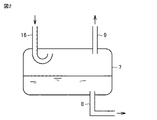
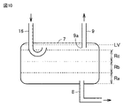
- FIG. 2 is a diagram schematically showing the configuration of the gas-liquid separator 7.
- the refrigerant is stored in the internal space of the gas-liquid separator 7.
- One end of the pipe 16 penetrates the upper wall of the gas-liquid separator 7 and is located in the internal space.
- the refrigerant that has passed through the pipe 16 is temporarily stored in the internal space of the gas-liquid separator 7.
- one end of the pipe 8 penetrates the lower wall of the gas-liquid separator 7 and is located at the lower part of the internal space.
- the liquid refrigerant accumulates in the lower part of the internal space. Therefore, the liquid refrigerant is discharged from the pipe 8.
- One end of the pipe 9 penetrates the upper wall of the gas-liquid separator 7 and is located at the upper part of the internal space.
- the gas refrigerant accumulates in the upper part of the internal space. Therefore, the gas refrigerant is discharged from the pipe 9.
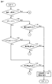
- FIG. 3 is a flowchart showing an example of the processing flow of the control device 70 according to the first embodiment.
- the control device 70 can determine the excess or deficiency of the amount of the refrigerant in the main circuit 50 based on the degree of supercooling of the refrigerant at the outlet of the condenser 2.
- the control device 70 calculates the degree of supercooling SC of the refrigerant at the outlet of the condenser 2 based on the discharge pressure P1 measured by the pressure sensor 31 and the temperature T measured by the temperature sensor 32. Specifically, the control device 70 specifies the saturation temperature CT of the refrigerant discharged from the compressor 1 based on the discharge pressure P1 of.
- control device 70 may define the temperature on the enthalpy of the critical point as the saturation temperature CT, and calculate the supercooling degree SC according to the above equation (1). That is, when the discharge pressure P1 exceeds the pressure at the critical point, the control device 70 determines the temperature at the critical point as the saturation temperature CT.
- the control device 70 compares the supercooling degree SC with the predetermined threshold value Th1 and determines whether or not SC ⁇ Th1 is satisfied (step S1).
- the threshold value Th1 for example, a value of the degree of supercooling when the compression ratio of the compressor 1 is near the lower limit of the allowable range can be adopted.
- the compression ratio is represented by a value obtained by dividing the pressure of the refrigerant at the discharge port 1o (that is, the discharge pressure P1) by the suction pressure which is the pressure of the refrigerant at the suction port 1i.
- the control device 70 compares the supercooling degree SC with the predetermined threshold value Th2, and determines whether or not SC> Th2 is satisfied (step S2).
- the threshold Th2 is larger than the threshold Th1.
- the threshold value Th2 is set so that supercooling can be ensured even with a pressure loss at the assumed maximum length of the liquid pipe 91 shown in FIG.
- step S2 When SC> Th2 is not satisfied (NO in step S2), that is, when Th2 ⁇ SC ⁇ Th1, the control device 70 determines that the amount of the refrigerant in the main circuit 50 is appropriate, and determines that the amount of the refrigerant in the main circuit 50 is appropriate, and the flow rate adjusting valve 13 and the electromagnetic wave. The valve 14 is maintained as it is and the process returns to step S1.
- step S2 the control device 70 determines that the amount of the refrigerant in the main circuit 50 is excessive, and steps S3 to S6 as a process for reducing the amount of the refrigerant in the main circuit 50. To execute.
- step S3 the control device 70 determines whether or not the opening degree of the flow rate adjusting valve 13 is the minimum, that is, whether or not the flow rate adjusting valve 13 is in the closed state.
- step S4 the control device 70 reduces the opening degree of the flow rate adjusting valve 13 by one step (step S4). As a result, the amount of the refrigerant flowing through the pipe 8 is reduced, and the liquid refrigerant is likely to accumulate in the gas-liquid separator 7. As a result, the amount of refrigerant in the main circuit 50 is reduced. After step S4, the control device 70 returns the process to step S1.
- the control device 70 determines whether or not the time T1 has elapsed since the opening degree of the flow rate adjusting valve 13 became the minimum (step S5). ).
- the time T1 is predetermined and is, for example, 10 minutes.
- the control device 70 has an internal timer for executing step S5, and counts the internal timer when it is determined that the opening degree of the flow rate adjusting valve 13 is the minimum in a state where the internal timer is reset. To start.
- the control device 70 may determine that the time T1 has elapsed since the opening degree of the flow rate adjusting valve 13 became the minimum because the count value of the internal timer reached the time T1.
- control device 70 When the time T1 has not elapsed since the opening degree of the flow rate adjusting valve 13 became the minimum (NO in step S5), the control device 70 returns the process to step S1 while maintaining the opening degree of the flow rate adjusting valve 13. ..
- step S5 When the time T1 has elapsed since the opening degree of the flow rate adjusting valve 13 became the minimum (YES in step S5), the control device 70 resets the internal timer for executing step S5 and opens the solenoid valve 14 (YES in step S5). Step S6). Even if the opening degree of the flow rate adjusting valve 13 is the minimum for the time T1, if SC> Th2 is still satisfied, the control response is poor with the flow rate adjusting valve 13 alone, and the liquid refrigerant is stored in the gas-liquid separator 7. Need to be promoted. By opening the solenoid valve 14, the gas refrigerant stored in the gas-liquid separator 7 is discharged to the pipe 9. As a result, the storage of the liquid refrigerant in the gas-liquid separator 7 is promoted, and the amount of the refrigerant in the main circuit 50 can be reduced. After step S6, the control device 70 returns the process to step S1.
- step S1 When SC ⁇ Th1 is not satisfied (NO in step S1), the control device 70 determines that the amount of refrigerant in the main circuit 50 is insufficient, and steps S7 to increase the amount of refrigerant in the main circuit 50. Execute S10.
- step S7 the control device 70 determines whether or not the opening degree of the flow rate adjusting valve 13 is the maximum.
- step S8 When the opening degree of the flow rate adjusting valve 13 is not the maximum (NO in step S7), the control device 70 raises the opening degree of the flow rate adjusting valve 13 by one step (step S8). As a result, the amount of the refrigerant flowing through the pipe 8 increases, and the liquid refrigerant is easily discharged from the gas-liquid separator 7. As a result, the amount of refrigerant in the main circuit 50 increases. After step S8, the control device 70 returns the process to step S1.
- the control device 70 determines whether or not the time T2 has elapsed since the opening degree of the flow rate adjusting valve 13 became the maximum (step S9). ).
- the time T2 is predetermined and is, for example, 10 minutes.
- the control device 70 has an internal timer for executing step S9, and counts the internal timer when it is determined that the opening degree of the flow rate adjusting valve 13 is the maximum in a state where the internal timer is reset. To start.
- the control device 70 may determine that the time T2 has elapsed since the opening degree of the flow rate adjusting valve 13 became maximum because the count value of the internal timer reached the time T2.
- step S9 If the time T2 has not elapsed since the opening of the flow rate adjusting valve 13 became maximum (NO in step S9), the control device 70 returns the process to step S1 while maintaining the opening of the flow rate adjusting valve 13. ..
- step S10 When the time T2 has elapsed from the maximum opening of the flow rate adjusting valve 13 (YES in step S9), the control device 70 resets the internal timer for executing step S9 and closes the solenoid valve 14 (YES in step S9). Step S10). Even if the opening degree of the flow rate adjusting valve 13 is maximum for the time T2, if SC ⁇ Th1, the control response is poor with the flow rate adjusting valve 13 alone, and the liquid refrigerant is discharged from the gas / liquid separator 7. Need to promote. By closing the solenoid valve 14, the gas refrigerant is stored in the gas-liquid separator 7, and the discharge of the liquid refrigerant is promoted. As a result, the rate of increase in the amount of refrigerant in the main circuit 50 can be increased. After step S10, the control device 70 returns the process to step S1.
- the control device 70 closes the solenoid valve 14 according to the degree of supercooling being less than the threshold value Th1 and the opening degree of the flow rate adjusting valve 13 being the maximum.
- the control device 70 opens the solenoid valve 14 according to the supercooling degree SC of the refrigerant flowing through the outlet of the condenser 2 exceeding the threshold value Th2 and the opening degree of the flow rate adjusting valve 13 being the minimum.
- the threshold Th2 is larger than the threshold Th1. That is, in the case of SC ⁇ Th1 or SC> Th2, first, the amount of refrigerant in the main circuit 50 is adjusted by controlling the opening degree of the flow rate adjusting valve 13.
- the opening degree of the flow rate adjusting valve 13 is controlled to the limit value, if the control response is poor, the open / closed state of the solenoid valve 14 is controlled.
- a refrigerant that can take a supercritical state such as a CO 2 refrigerant
- the pressure range that the refrigerant can take becomes wide, and the range that the amount of the refrigerant of the main circuit 50 should take becomes wide. Even in such a case, according to the refrigeration cycle apparatus 100 according to the first embodiment, the amount of the refrigerant in the main circuit 50 can be appropriately adjusted.
- Embodiment 2 In the transient operation until the stable state is reached, the discharge pressure P1 of the compressor 1 may rise sharply. Transient operation typically includes operation immediately after startup.
- the refrigerating cycle apparatus according to the second embodiment appropriately adjusts the amount of the refrigerant in the main circuit 50 in order to avoid such an increase in the discharge pressure P1.
- FIG. 4 is a diagram showing an internal configuration of the refrigeration cycle device 100A according to the second embodiment. As shown in FIG. 4, the refrigeration cycle device 100A differs from the refrigeration cycle device 100 shown in FIG. 1 in that it includes a pressure sensor 33.
- the pressure sensor 33 measures the intermediate pressure P2, which is the pressure of the injection port 1p of the compressor 1, and outputs the measurement result to the control device 70.
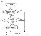
- FIG. 5 is a flowchart showing an example of the processing flow of the control device 70 according to the second embodiment.
- the control device 70 executes the flow shown in FIG. 5 in parallel with the flow shown in FIG.
- control device 70 determines whether or not the solenoid valve 14 is in the closed state (step S11). When the solenoid valve 14 is in the open state (NO in step S11), the control device 70 returns the process to step S11.
- the control device 70 compares the discharge pressure P1 of the compressor 1 with the threshold value Th3, and also compares the intermediate pressure P2 of the compressor 1 with the threshold value Th4. do.
- the control device 70 determines whether or not at least one of the following conditions (1) and (2) is satisfied (step S12).
- the threshold values Th3 and Th4 are set in advance according to the type of the refrigerant used and the like.
- the threshold Th3 is, for example, 10 MPa.
- the threshold Th4 is smaller than the threshold Th3, for example, 8.5 MPa.
- control device 70 If neither the condition (1) nor the condition (2) is satisfied (NO in step S12), the control device 70 returns the process to step S11.
- the control device 70 opens the solenoid valve 14 (step S13).
- the solenoid valve 14 By opening the solenoid valve 14, the gas refrigerant is discharged from the gas-liquid separator 7, and the storage of the liquid refrigerant in the gas-liquid separator 7 is promoted.
- the amount of refrigerant in the main circuit 50 decreases, and the discharge pressure P1 and the intermediate pressure P2 decrease.
- Embodiment 3 When the outside air temperature becomes low, the discharge pressure P1 of the compressor 1 decreases. When the discharge pressure P1 decreases, a compressed state (hereinafter, referred to as “overcompression”) in which the intermediate pressure P2 at the injection port 1p becomes higher than the discharge pressure P1 may occur in the compressor 1.
- overcompression a compressed state in which the intermediate pressure P2 at the injection port 1p becomes higher than the discharge pressure P1 may occur in the compressor 1.
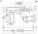
- FIG. 6 is a diagram showing an example of the internal configuration of the refrigeration cycle apparatus 100B according to the third embodiment.
- the refrigerating cycle device 100B has a pipe 18, a solenoid valve 19, 20, a capillary tube 22, a pressure sensor 34, and a temperature sensor as compared with the refrigerating cycle device 100 shown in FIG. It differs from 35 in that it is provided.
- the pipe 18, the solenoid valves 19, 20 and the capillary tube 22 are included in the injection circuit 60.
- the pipe 18 connects the branch point 21 of the pipe 10 and the suction port 1i of the compressor 1 in the main circuit 50. That is, the pipe 18 causes a part of the refrigerant flowing through the pipe 10 to flow to the suction side of the compressor 1.
- the branch point 21 is located between the economizer 12 and the injection port 1p.
- the solenoid valve 19 is provided between the branch point 21 and the injection port 1p in the pipe 10.
- the solenoid valve 20 is provided in the pipe 18.
- the solenoid valves 19 and 20 take either an open state or a closed state.
- the capillary tube 22 is provided between the branch point 21 and the solenoid valve 20 in the pipe 18.
- the capillary tube 22 decompresses the refrigerant separated from the pipe 10.
- the pressure sensor 34 measures the suction pressure P3, which is the pressure of the refrigerant on the suction side of the compressor 1, and outputs the measurement result to the control device 70.
- the temperature sensor 35 measures the outside air temperature AT and outputs the measurement result to the control device 70.
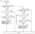
- FIG. 7 is a flowchart showing an example of the processing flow of the control device 70 according to the third embodiment.
- the control device 70 executes the flow shown in FIG. 7 in parallel with the flow shown in FIG.
- control device 70 determines whether or not the solenoid valve 14 is in the open state (step S21).
- the control device 70 determines whether or not the outside air temperature AT is less than the threshold value Th5 (step S22).
- the threshold Th5 is, for example, 0 ° C.
- the control device 70 compares the compression ratio P1 / P3, which is the value obtained by dividing the discharge pressure P1 by the suction pressure P3, with the threshold value Th6, and sets P1 / P3 ⁇ Th6. It is determined whether or not the condition is satisfied (step S23).
- the threshold Th6 is predetermined to be slightly larger than the compression ratio when overcompression occurs, and is, for example, 1.4. If AT ⁇ Th5 is not satisfied (NO in step S22) or P1 / P3 ⁇ Th6 is not satisfied (NO in step S23), the control device 70 returns the process to step S21.
- the control device 70 closes the solenoid valves 14 and 19 and opens the solenoid valve 20 (step S24).
- the solenoid valve 14 By closing the solenoid valve 14, the gas refrigerant is not discharged from the gas-liquid separator 7, and the discharge of the liquid refrigerant from the gas-liquid separator 7 is promoted.
- the solenoid valve 19 even if overcompression occurs due to the low outside air temperature AT, it is possible to prevent the backflow of the refrigerant from the injection port 1p to the gas-liquid separator 7.
- the solenoid valve 20 is opened, the refrigerant discharged from the gas-liquid separator 7 is returned to the main circuit 50 through the pipe 18. As a result, the amount of refrigerant in the main circuit 50 increases, and the occurrence of overcompression can be suppressed.
- the refrigerant passing through the pipe 18 is depressurized by the capillary tube 22. Therefore, the pressure difference of the refrigerant at the confluence of the pipe 18 and the pipe constituting the main circuit 50 can be reduced.
- the solenoid valve 20 is opened to open the main circuit 50 from the pipe 18. Refrigerant flows rapidly into the pipe. When such a rapid inflow of the refrigerant occurs, foaming may occur in the liquid refrigerant stored in the gas-liquid separator 7.
- the liquid refrigerant may be discharged from the pipe 9 provided in the upper part of the gas-liquid separator 7.
- the capillary tube 22 By providing the capillary tube 22, such bubbling and discharge of the liquid refrigerant from the pipe 9 are suppressed. If the difference between the pressure of the refrigerant at the branch point 21 and the suction pressure P3 of the compressor 1 is within the allowable range, the capillary tube 22 may be omitted.
- step S21 When the solenoid valve 14 is in the closed state (NO in step S21), the control device 70 determines whether or not the solenoid valve 20 is in the open state (step S25). When the solenoid valve 20 is in the closed state (NO in step S25), the control device 70 returns the process to step S21.
- the control device 70 determines whether or not the outside air temperature AT is less than the threshold value Th5 (step S26). When AT ⁇ Th5 is satisfied (YES in step S26), the control device 70 compares the compression ratio P1 / P3 with the threshold value Th6, and determines whether or not P1 / P3 ⁇ Th6 is satisfied (step S27). When P1 / P3 ⁇ Th6 is satisfied (YES in step S27), the control device 70 returns the process to step S21.
- the control device 70 opens the solenoid valves 14 and 19 and closes the solenoid valve 20 (step). S28). If NO in step S26 or NO in step S27, it is unlikely that overcompression due to the low outside air temperature AT will occur. Therefore, when the solenoid valve 14 is opened, the gas refrigerant is discharged from the gas-liquid separator 7. When the solenoid valve 19 is opened and the solenoid valve 20 is closed, the refrigerant flows into the injection port 1p, the power consumption is reduced, and the capacity is improved.
- Embodiment 4 The refrigeration cycle apparatus according to the first embodiment determines the excess or deficiency of the amount of the refrigerant in the main circuit 50 by using the supercooling degree SC of the refrigerant that has passed through the condenser 2.
- the evaporation temperature ET of the refrigerant sucked into the compressor 1 and the liquid level of the gas-liquid separator 7 are used to exceed the amount of the refrigerant in the main circuit 50. Judge the shortage.
- FIG. 8 is a diagram showing an example of the internal configuration of the refrigeration cycle apparatus 100C according to the fourth embodiment.
- the refrigerating cycle apparatus 100C includes a pressure sensor 34 and a liquid level sensor 36 instead of the pressure sensor 31 and the temperature sensor 32 as compared with the refrigerating cycle apparatus 100 shown in FIG. It's different.
- the pressure sensor 34 measures the suction pressure P3 of the compressor 1 as described in the third embodiment, and outputs the measurement result to the control device 70.
- the liquid level sensor 36 is a sensor that detects the liquid level (the height of the liquid level) of the gas-liquid separator 7.
- the liquid level sensor 36 outputs the detection result to the control device 70.
- the control device 70 calculates the evaporation temperature ET of the refrigerant sucked into the compressor 1 based on the suction pressure P3.
- the control device 70 stores in advance a correspondence table in which a plurality of evaporation temperature zones and a plurality of height ranges are associated with each other.
- the control device 70 specifies the evaporation temperature zone to which the evaporation temperature ET belongs among the plurality of evaporation temperature zones, and determines the height range corresponding to the specified evaporation temperature zone among the plurality of height ranges as the target height range. ..
- the control device 70 controls the opening degree of the flow rate adjusting valve 13 and the open / closed state of the solenoid valve 14 so that the liquid level of the gas-liquid separator 7 falls within the target height range.
- FIG. 9 is a diagram showing an example of a corresponding table 45 stored in the control device 70 according to the fourth embodiment.
- the corresponding table 45 associates the evaporation temperature zone below ⁇ 30 ° C. with the height range Rc, and sets the evaporation temperature zone below ⁇ 30 ° C. and below ⁇ 10 ° C. and the height range Rb.
- the evaporation temperature zone of -10 ° C or higher and the height range Ra are associated.
- FIG. 10 is a diagram showing an example of a height range set for the gas-liquid separator 7 in the fourth embodiment.
- the height range Rb corresponding to the evaporation temperature zone of ⁇ 30 ° C. or higher and lower than ⁇ 10 ° C. is set higher than the height range Ra corresponding to the evaporation temperature zone of ⁇ 10 ° C. or higher.
- the height range corresponding to the lower temperature evaporation temperature zone of any two evaporation temperature zones selected from the plurality of evaporation temperature zones is the higher temperature evaporation temperature zone of the two evaporation temperature zones. It is set higher than the height range corresponding to.
- the amount of refrigerant in the main circuit 50 is an appropriate amount. Is adjusted to.
- the refrigerant discharged from the compressor 1 includes the refrigerating machine oil of the compressor 1. Therefore, the refrigerating machine oil is also contained in the liquid refrigerant stored in the gas-liquid separator 7. It is preferable that the refrigerating machine oil discharged from the compressor 1 is recovered by the compressor 1. When the refrigerating machine oil is dissolved in the refrigerant, the liquid refrigerant is discharged from the gas-liquid separator 7 through the pipe 8, and the refrigerating machine oil is recovered in the compressor 1.
- the refrigerating machine oil is stored in the lower part of the gas-liquid separator 7.
- the refrigerating machine oil stationed in the lower part of the gas-liquid separator 7 is discharged through the pipe 8 and collected in the compressor 1.
- the refrigerating machine oil is accumulated in a layer on the liquid refrigerant in the gas-liquid separator 7. In this case, the liquid refrigerant is mainly discharged from the pipe 8, and the refrigerating machine oil is not easily discharged. Therefore, the refrigerating machine oil in the gas-liquid separator 7 is difficult to be recovered by the compressor 1.
- the control device 70 pipes the liquid level of the gas-liquid separator 7 to the compressor 1 at predetermined intervals in order to allow the compressor 1 to recover the refrigerating machine oil that is insoluble in the refrigerant and has a lighter specific density than the refrigerant.
- the reference height LV (see FIG. 10) higher than one end 9a of the above is reached.
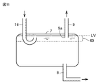
- FIG. 11 is a diagram showing the state of the gas-liquid separator 7 when the liquid level reaches the reference height LV.
- one end 9a of the pipe 9 is located in the gas-liquid separator 7. Since the liquid level reaches the reference height LV higher than the one end 9a of the pipe 9, the one end 9a of the pipe 9 is located in the layer 40 of the refrigerating machine oil stored above the liquid refrigerant. As a result, the refrigerating machine oil can be recovered in the compressor 1 through the pipe 9.
- FIG. 12 is a flowchart showing the flow of steps S31 to S37 in the processing of the control device 70 according to the fourth embodiment.
- FIG. 13 is a flowchart showing the flow of steps S38 to S44 in the processing of the control device 70 according to the fourth embodiment.
- FIG. 14 is a flowchart showing the flow of steps S45 to S47 in the processing of the control device 70 according to the fourth embodiment.
- the control device 70 determines whether or not the time T3 has elapsed since the control device 70 was started or the liquid level level reached the reference height LV last time (step S31).
- the time T3 is a predetermined cycle, for example, 60 minutes.
- the control device 70 has an internal timer for executing step S31, resets the internal timer when the refrigeration cycle device 100C is started, and starts counting the internal timer.
- the control device 70 may determine YES in step S31 according to the fact that the count value of the internal timer has reached the time T3.
- the control device 70 calculates the evaporation temperature ET based on the suction pressure P3 and determines whether or not ET ⁇ -30 ° C. is satisfied (step S32). ). When ET ⁇ -30 ° C. is not satisfied (NO in step S32), the control device 70 determines whether or not ⁇ 30 ° C. ⁇ ET ⁇ -10 ° C. is satisfied (step S33).
- the control device 70 covers the height range Rc corresponding to the evaporation temperature zone below -30 ° C from the corresponding table 45 shown in FIG. Read as.
- the control device 70 determines whether or not the liquid level level detected by the liquid level sensor 36 belongs to the target height range (step S34).
- the control device 70 When ⁇ 30 ° C. ⁇ ET ⁇ -10 ° C. is satisfied (YES in step S33), the control device 70 indicates the height corresponding to the evaporation temperature zone of ⁇ 30 ° C. or higher and lower than ⁇ 10 ° C. from the corresponding table 45 shown in FIG.
- the range Rb is read out as the target height range.
- the control device 70 determines whether or not the liquid level level detected by the liquid level sensor 36 belongs to the target height range (step S35).
- the control device 70 sets the height range Ra corresponding to the evaporation temperature zone of ⁇ 10 ° C. or higher from the corresponding table 45 shown in FIG. Read as the target height range.
- the control device 70 determines whether or not the liquid level level detected by the liquid level sensor 36 belongs to the target height range (step S36).
- step S37 the control device 70 maintains the opening degree of the flow rate adjusting valve 13 as it is (step S37). After step S37, the control device 70 returns the process to step S31.
- control device 70 determines whether or not the liquid level level exceeds the upper limit of the target height range (step S38).
- step S39 the control device 70 determines whether or not the opening degree of the flow rate adjusting valve 13 is the maximum (step S39).
- step S40 the control device 70 increases the opening degree of the flow rate adjusting valve 13 by one step (step S40).
- step S41 When the opening degree of the flow rate adjusting valve 13 is maximum (YES in step S39), the control device 70 closes the solenoid valve 14 (step S41). By closing the solenoid valve 14, the gas refrigerant is stored in the gas-liquid separator 7, and the discharge of the liquid refrigerant is promoted. As a result, as the liquid level approaches the target height range, the amount of refrigerant in the main circuit 50 increases. After step S41, the control device 70 returns the process to step S31.
- step S38 When the liquid level does not exceed the upper limit of the target height range (NO in step S38), that is, when the liquid level level is less than the lower limit of the target height range, the control device 70 controls the opening degree of the flow rate adjusting valve 13. Is the minimum (step S42). When the opening degree of the flow rate adjusting valve 13 is not the minimum (NO in step S42), the control device 70 reduces the opening degree of the flow rate adjusting valve 13 by one step (step S43). As a result, the amount of the refrigerant flowing through the pipe 8 is reduced, and the liquid refrigerant is likely to be stored in the gas-liquid separator 7. As a result, the liquid level approaches the target height range, and the amount of the refrigerant in the main circuit 50 decreases. After step S43, the control device 70 returns the process to step S31.
- step S43 the control device 70 opens the solenoid valve 14 (step S43).
- the solenoid valve 14 By opening the solenoid valve 14, the gas refrigerant is discharged from the gas-liquid separator 7, and the liquid refrigerant is more likely to be stored in the gas-liquid separator 7.
- the control device 70 returns the process to step S31.
- the control device 70 opens the solenoid valve 14 and adjusts the flow rate until the liquid level reaches the reference height LV.
- the opening degree of the valve 13 is set to the minimum (that is, closed) (step S45).
- the flow rate adjusting valve 13 is closed, so that the discharge of the liquid refrigerant from the gas-liquid separator 7 is stopped.
- the solenoid valve 14 is opened, the gas refrigerant is discharged from the gas-liquid separator 7, and the storage of the liquid refrigerant in the gas-liquid separator 7 is promoted.
- the reference height LV is higher than one end of the pipe 9.
- the layer 40 of the refrigerating machine oil is discharged from the pipe 9 and the refrigerating machine oil is recovered in the compressor 1 between the time when the liquid level reaches one end of the pipe 9 and the time when the liquid level reaches the reference height LV.
- the control device 70 may wait for a certain period of time after the liquid level reaches the reference height LV. As a result, the refrigerating machine oil in the gas-liquid separator 7 is more reliably recovered in the compressor 1.
- step S46 the control device 70 returns the opening / closing state of the flow rate adjusting valve 13 and the open / closed state of the solenoid valve 14 to the states before the start of step S45 (step S46).
- step S47 the control device 70 resets the internal timer used for executing step S31 (step S47).
- step S45 is executed each time the time T3 elapses, and the refrigerating machine oil in the gas-liquid separator 7 is periodically collected in the compressor 1.
- Embodiment 5 The refrigerating cycle apparatus 100C according to the fourth embodiment determines the excess or deficiency of the amount of the refrigerant in the main circuit 50 by using the evaporation temperature ET of the refrigerant sucked into the compressor 1 and the liquid level height of the gas-liquid separator 7. do.
- the excess or deficiency of the amount of the refrigerant in the main circuit 50 is determined by using the outside air temperature, the evaporation temperature ET, and the liquid level height of the gas-liquid separator 7.
- control device 70 determines the target height range according to the outside air temperature AT and the evaporation temperature ET, and adjusts the flow rate so that the liquid level of the gas-liquid separator 7 falls within the target height range.
- the opening degree of the valve 13 and the open / closed state of the solenoid valve 14 are controlled.
- FIG. 15 is a diagram showing an example of the internal configuration of the refrigeration cycle apparatus 100D according to the fifth embodiment.
- the refrigeration cycle device 100D differs from the refrigeration cycle device 100C shown in FIG. 8 in that it further includes a temperature sensor 35.
- the temperature sensor 35 measures the outside air temperature AT as described in the third embodiment, and outputs the measurement result to the control device 70.
- the control device 70 stores in advance a correspondence table in which a plurality of evaporation temperature zones and a plurality of height ranges are associated with each of the plurality of outside air temperature zones.
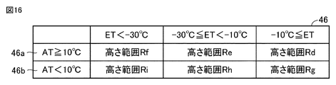
- FIG. 16 is a diagram showing an example of a corresponding table 46 stored in the control device 70 according to the fifth embodiment.
- the corresponding table 46 includes a record 46a corresponding to an outside air temperature zone of 10 ° C. or higher and a record 46b corresponding to an outside air temperature zone of less than 10 ° C.
- Each of the records 46a and 46b associates the evaporation temperature zone of less than -30 ° C, the evaporation temperature zone of -30 ° C or more and less than -10 ° C, and the evaporation temperature zone of -10 ° C or more with the height range. That is, each of the records 46a and 46b is correspondence information in which a plurality of evaporation temperature zones and a plurality of height ranges are associated with each other.
- the record 46a associates the evaporation temperature zone of less than -30 ° C with the height range Rf, associates the evaporation temperature zone of -30 ° C or more and less than -10 ° C with the height range Re, and evaporates at -10 ° C or more.
- the record 46b associates the evaporation temperature zone of less than -30 ° C with the height range Ri, associates the evaporation temperature zone of -30 ° C or more and less than -10 ° C with the height range Rh, and evaporates at -10 ° C or more.
- FIG. 17 is a diagram showing an example of a height range set for the gas-liquid separator 7 in the fifth embodiment.
- the height range Re Corresponding to the evaporation temperature zone of -30 ° C or higher and lower than -10 ° C.
- Rh is set higher than the height ranges Rd and Rg corresponding to the evaporation temperature zone of ⁇ 10 ° C. or higher, respectively.
- the height ranges Rf, Re, and Rd corresponding to the outside air temperature zone of 10 ° C. or higher are set lower than the height ranges Ri, Rh, Rg corresponding to the outside air temperature zone of less than 10 ° C.
- the plurality of height ranges included in the record corresponding to the high temperature outside air temperature zone among any two outside air temperature zones selected from the plurality of outside air temperature zones are the two outside air temperature zones. It is set lower than the height range contained in the record corresponding to the cold outside air temperature zone.
- the amount of refrigerant in the main circuit 50 is controlled by controlling the opening degree of the flow rate adjusting valve 13 and the open / closed state of the solenoid valve 14 so that the liquid level level falls within the target height range corresponding to the outside air temperature AT and the evaporation temperature ET. Is adjusted to the appropriate amount.
- FIG. 18 is a flowchart showing the flow of steps S51 to S59 in the processing of the control device 70 according to the fifth embodiment.
- step S51 the control device 70 determines whether or not the time T3 has elapsed since the control device 70 was started or the liquid level level reached the reference height LV last time (step S51).
- the details of step S51 are the same as those of step S31 shown in FIG.
- control device 70 determines whether or not the outside air temperature AT received from the temperature sensor 35 satisfies AT ⁇ 10 ° C. (step S52).
- control device 70 When AT ⁇ 10 ° C. is not satisfied (NO in step S52), that is, when AT ⁇ 10 ° C. is satisfied, the control device 70 corresponds to the outside air temperature zone of less than 10 ° C. in the corresponding table 46 shown in FIG. Read the record 46b (S53).
- control device 70 calculates the evaporation temperature ET based on the suction pressure P3, and determines whether or not ET ⁇ -30 ° C. is satisfied (step S54). When ET ⁇ -30 ° C. is not satisfied (NO in step S54), the control device 70 determines whether or not ⁇ 30 ° C. ⁇ ET ⁇ -10 ° C. is satisfied (step S55).
- the control device 70 covers the height range Ri corresponding to the evaporation temperature zone below -30 ° C from the record 46b read in step S53. Read as. The control device 70 determines whether or not the liquid level level detected by the liquid level sensor 36 belongs to the target height range (step S56).
- the control device 70 When -30 ° C ⁇ ET ⁇ -10 ° C is satisfied (YES in step S55), the control device 70 has a height corresponding to the evaporation temperature zone of ⁇ 30 ° C. or higher and lower than ⁇ 10 ° C. from the record 46b read in step S53. The range Rh is read out as the target height range. The control device 70 determines whether or not the liquid level level detected by the liquid level sensor 36 belongs to the target height range (step S57).
- the control device 70 obtains a height range Rg corresponding to the evaporation temperature zone of ⁇ 10 ° C. or higher from the record 46b read in step S53. Read as the target height range. The control device 70 determines whether or not the liquid level level detected by the liquid level sensor 36 belongs to the target height range (step S58).
- step S59 the control device 70 returns the process to step S51.
- FIG. 19 is a flowchart showing the flow of steps S60 to S66 in the processing of the control device 70 according to the fifth embodiment.
- control device 70 corresponds to the outside air temperature zone of 10 ° C. or higher in the corresponding table 46 shown in FIG. Read the record 46a (S60).
- control device 70 calculates the evaporation temperature ET based on the suction pressure P3, and determines whether or not ET ⁇ -30 ° C. is satisfied (step S61). When ET ⁇ -30 ° C. is not satisfied (NO in step S61), the control device 70 determines whether or not ⁇ 30 ° C. ⁇ ET ⁇ -10 ° C. is satisfied (step S62).
- the control device 70 covers the height range Rf corresponding to the evaporation temperature zone below -30 ° C from the record 46a read in step S60. Read as. The control device 70 determines whether or not the liquid level level detected by the liquid level sensor 36 belongs to the target height range (step S63).
- the control device 70 When ⁇ 30 ° C. ⁇ ET ⁇ -10 ° C. is satisfied (YES in step S62), the control device 70 indicates the height corresponding to the evaporation temperature zone of ⁇ 30 ° C. or higher and lower than ⁇ 10 ° C. from the record 46a read in step S59. Read the range Re as the target height range. The control device 70 determines whether or not the liquid level level detected by the liquid level sensor 36 belongs to the target height range (step S64).
- the control device 70 sets the height range Rd corresponding to the evaporation temperature zone of ⁇ 10 ° C. or higher from the record 46a read in step S59. Read as the target height range.
- the control device 70 determines whether or not the liquid level level detected by the liquid level sensor 36 belongs to the target height range (step S65).
- step S66 the control device 70 returns the process to step S51.
- control device 70 executes steps S38 to S44 shown in FIG. 13 and then returns the process to step S51, as in the fourth embodiment.
- step S51 If YES in step S51, the process is returned to step S51 after executing steps S45 to S47 shown in FIG. 14 as in the fourth embodiment.
- Embodiment 6 In the above embodiments 1 to 5, the economizer 12 exchanges heat between the refrigerant flowing through the pipe 10 and the refrigerant flowing out of the condenser 2. On the other hand, in the refrigerating cycle apparatus according to the sixth embodiment, the economizer 12 exchanges heat between the refrigerant flowing through the pipe 9 and the refrigerant flowing out of the condenser 2.
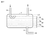
- FIG. 20 is a diagram showing an internal configuration of the refrigeration cycle apparatus 100E according to the sixth embodiment.
- the economizer 12 is arranged between the solenoid valve 14 and the confluence point 11 in the pipe 9.
- the pipe 8 joins the pipe 9 at the confluence 11 without passing through the economizer 12.
- the wetness of the refrigerant in the gas-liquid two-phase state flowing into the injection port 1p of the compressor 1 increases, and the ability to lower the temperature of the refrigerant discharged from the compressor 1 can be enhanced. ..
- the wetness of the refrigerant in the gas-liquid two-phase state is adjusted by the opening degree of the flow rate adjusting valve 13 provided in the pipe 8.
- Embodiment 7 In the refrigeration cycle apparatus according to the seventh embodiment, the economizer 12 exchanges heat between the refrigerant flowing through the pipe 8 and the refrigerant flowing out of the condenser 2.
- FIG. 21 is a diagram showing an internal configuration of the refrigeration cycle device 100F according to the seventh embodiment.
- the economizer 12 is arranged between the flow rate adjusting valve 13 and the confluence point 11 in the pipe 8.
- the pipe 9 joins the pipe 8 at the confluence 11 without passing through the economizer 12.
- the economizer 12 can improve the efficiency of heat exchange by utilizing the latent heat of vaporization of the liquid refrigerant flowing through the pipe 8.
- Embodiment 8 The refrigeration cycle apparatus according to the eighth embodiment can switch the path of the injection circuit 60 shown in FIGS. 1, 20 and 21.
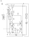
- FIG. 22 is a diagram showing an internal configuration of the refrigeration cycle device 100G according to the eighth embodiment. As shown in FIG. 22, the refrigerating cycle device 100G differs from the refrigerating cycle device 100 shown in FIG. 1 in that it includes pipes 23 to 30 and three-way valves 47 and 48.
- the three-way valve 47 has three ports 47a, 47b, 47c, and switches between a state in which the port 47a and the port 47b communicate with each other and a state in which the port 47a and the port 47c communicate with each other.
- the three-way valve 48 has three ports 48a, 48b, and 48c, and switches between a state in which the port 48a and the port 48b communicate with each other and a state in which the port 48a and the port 48c communicate with each other.
- the pipe 23 is provided to discharge the liquid refrigerant from the gas / liquid separator 7.
- the pipe 23 connects the gas-liquid separator 7 and the port 47a of the three-way valve 47.
- the flow rate adjusting valve 13 is provided in the pipe 23.
- One end of the pipe 24 is connected to the port 47b of the three-way valve 47.
- One end of the pipe 25 is connected to the port 47c of the three-way valve 47.
- the pipe 26 is provided to discharge the gas refrigerant from the gas-liquid separator 7.
- the pipe 26 connects the gas-liquid separator 7 and the port 48a of the three-way valve 48.
- the solenoid valve 14 is provided in the pipe 26.
- One end of the pipe 27 is connected to the port 48b of the three-way valve 48.
- One end of the pipe 28 is connected to the port 48c of the three-way valve 48.
- the other end of the pipe 24 is connected to the other end of the pipe 27.
- the other end of the pipe 25 is connected to the other end of the pipe 28.
- the pipe 29 connects the connection point 11a of the pipes 24 and 27 and the connection point 11b of the pipes 25 and 28.
- the pipe 29 passes through the economizer 12. Therefore, heat exchange is performed between the refrigerant flowing through the pipe 29 and the refrigerant passing through the condenser 2.
- the pipe 30 connects the connection points 11b of the pipes 25 and 28 and the injection port 1p of the compressor 1.
- the control device 70 switches the three-way valves 47 and 48 to one of the following first to third states.
- First state A state in which the port 47a and the port 47b of the three-way valve 47 are communicated with each other, and the port 48a and the port 48b of the three-way valve 48 are communicated with each other.
- Second state A state in which the port 47a and the port 47c of the three-way valve 47 are communicated with each other, and the port 48a and the port 48b of the three-way valve 48 are communicated with each other.
- Third state A state in which the port 47a and the port 47b of the three-way valve 47 are communicated with each other, and the port 48a and the port 48c of the three-way valve 48 are communicated with each other.
- connection point 11a When the three-way valves 47 and 48 are switched to the first state, the refrigerant that has passed through the flow rate adjusting valve 13 is flowed to the connection point 11a, and the refrigerant that has passed through the solenoid valve 14 is flowed to the connection point 11a.
- the refrigerant merged at the connection point 11a flows through the pipes 29 and 30 to the compressor 1 after heat exchange with the refrigerant passing through the condenser 2 by the economizer 12.
- the path of the injection circuit 60 of the first embodiment is realized. That is, the pipes 23 and 24 constitute the pipe 8 of FIG. 1, the pipes 26 and 27 form the pipe 9 of FIG. 1, and the pipes 29 and 30 form the pipe 10 of FIG.
- the connection point 11a corresponds to the confluence point 11 in FIG.
- the refrigerant that has passed through the flow rate adjusting valve 13 is flowed to the connection point 11b.
- the refrigerant that has passed through the solenoid valve 14 flows through the pipes 27 and 29 to the connection point 11b. That is, the refrigerant that has passed through the solenoid valve 14 exchanges heat with the refrigerant that has passed through the condenser 2 in the economizer 12, and then merges with the refrigerant that has passed through the flow rate adjusting valve 13 at the connection point 11b.
- the refrigerant that has passed through the flow rate adjusting valve 13 does not pass through the economizer 12.
- connection point 11b The refrigerant merged at the connection point 11b flows to the compressor 1 through the pipe 30.
- the path of the injection circuit 60 of the sixth embodiment is realized. That is, the pipes 23 and 25 constitute the pipe 8 of FIG. 20, the pipes 26, 27 and 29 form the pipe 9 of FIG. 20, and the pipe 30 constitutes the pipe 10 of FIG. 20.
- the connection point 11b corresponds to the confluence point 11 in FIG.
- the refrigerant that has passed through the solenoid valve 14 is flowed to the connection point 11b.
- the refrigerant that has passed through the flow rate adjusting valve 13 flows through the pipes 24 and 29 to the connection point 11b. That is, the refrigerant that has passed through the flow control valve 13 exchanges heat with the refrigerant that has passed through the condenser 2 in the economizer 12, and then merges with the refrigerant that has passed through the solenoid valve 14 at the connection point 11b.
- the refrigerant that has passed through the solenoid valve 14 does not pass through the economizer 12.
- the refrigerant merged at the connection point 11b flows to the compressor 1 through the pipe 30.
- the path of the injection circuit 60 of the seventh embodiment is realized. That is, the pipes 23, 24, and 29 constitute the pipe 8 in FIG. 21, the pipes 26 and 28 form the pipe 9 in FIG. 21, and the pipe 30 constitutes the pipe 10 in FIG.
- the connection point 11b corresponds to the confluence point 11 in FIG.
- the three-way valves 47 and 48 switch the pipe passing through the economizer 12 to any of the pipe 8, the pipe 9, and the pipe 10.
- the three-way valves 47 and 48 When the three-way valves 47 and 48 are in the first state, the refrigerant flowing through the main circuit 50 is efficiently supercooled, and the performance of the refrigeration cycle device 100G is enhanced.
- the liquid refrigerant that has passed through the flow rate adjusting valve 13 is directly sent to the compressor 1 without passing through the economizer 12. Therefore, it becomes easy to lower the discharge temperature of the compressor 1.
- the three-way valves 47 and 48 are in the third state, only the liquid refrigerant that has passed through the flow rate adjusting valve 13 passes through the economizer 12, so that the gas refrigerant is sent to the compressor 1. Therefore, it becomes easy to raise the discharge temperature of the compressor 1.
- the control device 70 may set the three-way valves 47 and 48 to the first state except when the discharge temperature of the compressor 1 changes transiently. Then, the control device 70 may switch the three-way valves 47 and 48 to the second state when the discharge temperature of the compressor 1 rises sharply (for example, when the temperature reaches 115 ° C. or higher). Further, if the discharge temperature drops and the degree of superheat of the discharged refrigerant cannot be secured (for example, when the degree of superheat is 20 K or less), the control device 70 can switch the three-way valves 47 and 48 to the third state. good.
- the injection circuit 60 may be provided with the pipe 18, the solenoid valves 19, 20 and the capillary tube 22 as in the third embodiment.
- the liquid level sensor 36 detects the liquid level of the gas-liquid separator 7. Therefore, in order to accurately detect the liquid level, it is preferable that the liquid level is stable in the gas-liquid separator 7.
- the capillary tube 22 is provided between the branch point 21 and the solenoid valve 20 in the pipe 18.
Landscapes
- Engineering & Computer Science (AREA)
- Physics & Mathematics (AREA)
- Mechanical Engineering (AREA)
- Thermal Sciences (AREA)
- General Engineering & Computer Science (AREA)
- Air Conditioning Control Device (AREA)
Abstract
インジェクション回路(60)は、冷媒の一部を気液分離する気液分離器(7)と、記気液分離器(7)から液冷媒を排出する第1配管(8)と、気液分離器(7)からガス冷媒を排出する第2配管(9)と、第1配管(8)および第2配管(9)を流れる冷媒を合流させて、圧縮機(1)のインジェクションポート(1p)に流入させる第3配管(10)と、第1配管(8)に設けられた流量調整弁(13)と、第2配管(9)に設けられた電磁弁(14)と、を含む。冷凍サイクル装置(100)は、流量調整弁(13)の開度と電磁弁(14)の開閉状態とを制御することにより、主回路(50)内の冷媒量を調整する制御装置(70)を備える。
Description
本開示は、冷凍サイクル装置に関する。
従来、冷凍サイクルの消費電力削減および能力向上などを目的として、中間インジェクション方式の冷凍サイクル装置が知られている。この冷凍サイクル装置は、主回路を循環している冷媒の一部をインジェクション回路に分流させ、圧縮機の中間圧部へインジェクションさせる。
特開2016-156557号公報(特許文献1)には、インジェクション回路に気液分離器を設け、気相の多い流れと液相の多い流れとを第1,第2のインジェクション経路にそれぞれ流す冷凍サイクル装置が開示されている。これにより、第2のインジェクション経路を流れる冷媒の質量流量が大きくなる。
特許文献1に開示の冷凍サイクル装置では、主回路に設けられたレシーバタンクに余剰な液冷媒を溜めることにより、主回路の冷媒量が調整される。冷媒を貯めるための部材として気液分離器の他にレシーバタンクが設けられるため、冷凍サイクル装置が大型化する。
本開示は、上記課題を解決するためになされたものであって、その目的は、小型化の可能な中間インジェクション方式の冷凍サイクル装置を提供することである。
本開示のある局面の冷凍サイクル装置は、冷媒が圧縮機、凝縮器、減圧装置および蒸発器の順に循環する主回路と、凝縮器から減圧装置へ流れる冷媒の一部を分流して圧縮機に流入させるインジェクション回路と、を備える。インジェクション回路は、冷媒の一部を気液分離する気液分離器を含む。インジェクション回路は、気液分離器から液冷媒を排出する第1配管と、気液分離器からガス冷媒を排出する第2配管と、第1配管を流れる冷媒と第2配管を流れる冷媒とを合流させて、圧縮機のインジェクションポートに流入させる第3配管と、を含む。さらに、インジェクション回路は、第1配管に設けられた流量調整弁と、第2配管に設けられた第1電磁弁と、を含む。冷凍サイクル装置は、さらに、流量調整弁の開度と第1電磁弁の開閉状態とを制御することにより、主回路内の冷媒量を調整する制御装置を備える。
本開示によれば、インジェクション回路に設けられた気液分離器を用いて、主回路内の冷媒量が調整される。これにより、特許文献1のように気液分離器の他にレシーバタンクを設ける必要がなく、冷凍サイクル装置の小型化が可能となる。
実施の形態1.
<冷凍サイクル装置の構成>
図1は、実施の形態1に係る冷凍サイクル装置100の内部構成を示す図である。図1に示す冷凍サイクル装置100は、たとえば部屋、倉庫、ショーケース、または冷蔵庫などの冷却対象空間の冷却を行う。
<冷凍サイクル装置の構成>
図1は、実施の形態1に係る冷凍サイクル装置100の内部構成を示す図である。図1に示す冷凍サイクル装置100は、たとえば部屋、倉庫、ショーケース、または冷蔵庫などの冷却対象空間の冷却を行う。
冷凍サイクル装置100は、熱源側ユニット80と利用側ユニット90とを含んでいる。熱源側ユニット80と利用側ユニット90とは、液配管91およびガス配管92によって接続される。液配管91には、熱源側ユニット80から利用側ユニット90に向けて過冷却の液冷媒が流れる。ガス配管92には、利用側ユニット90から熱源側ユニット80に向けてガス冷媒が流れる。液配管91およびガス配管92の長さは、熱源側ユニット80および利用側ユニット90の設置位置に応じて調整される。なお、図1に示す例では、1台の熱源側ユニット80と1台の利用側ユニット90とが示されるが、これらの台数は限定されない。熱源側ユニット80および利用側ユニット90の少なくとも一方が2台以上であってもよい。
冷凍サイクル装置100は、冷媒が圧縮機1、凝縮器2、減圧装置3,4および蒸発器5の順に循環する主回路50と、凝縮器2から減圧装置3へ流れる冷媒の一部を分流して圧縮機1に流入させるインジェクション回路60と、を備える。圧縮機1、凝縮器2、減圧装置3およびインジェクション回路60は、熱源側ユニット80に設けられる。減圧装置4および蒸発器5は、利用側ユニット90に設けられる。冷媒は、たとえばCO2冷媒である。
圧縮機1は、たとえばスクロール圧縮機であり、吸入口1iと吐出口1oとを有する。圧縮機1は、吸入口1iから吸入された冷媒を圧縮して、吐出口1oから吐出する。圧縮機1は、インバータにより制御される駆動モータ(図示せず)によって駆動される容積式圧縮機であり、運転容量が可変となっている。さらに、圧縮機1は、圧縮室の中間圧部に通じるインジェクションポート1pを有する。
凝縮器2は、配管を介して圧縮機1の吐出口1oに接続され、圧縮機1から吐出された冷媒を凝縮させる。凝縮器2は、圧縮機1から吐出された冷媒とファン17によって送られる外気との間で熱交換を行なう。これにより、冷媒の熱が外気に放散し、冷媒が冷却される。凝縮器2は、たとえば伝熱管と複数のフィンとを有するフィンアンドチューブ型熱交換器である。
減圧装置3,4は、電子膨張弁、温度式膨張弁などによって構成され、凝縮器2を通過した冷媒を減圧する。具体的に、減圧装置3,4は、冷媒を減圧し膨張させるとともに、主回路50を流れる冷媒の流量を調整する。
蒸発器5は、減圧装置3,4によって減圧され膨張した冷媒と利用側ユニット90内の空気とを熱交換し、冷媒を蒸発させる。蒸発器5は、たとえば伝熱管と複数のフィンとを有するフィンアンドチューブ型熱交換器である。
インジェクション回路60は、配管8,9,10,16と、流量調整弁6,13と、気液分離器7と、電磁弁14と、を含む。
配管16は、主回路50における凝縮器2と減圧装置3との間の分岐点15と気液分離器7とを接続する。配管16は、凝縮器2から減圧装置3へ流れる冷媒の一部を分流して、気液分離器7に流入させる。
流量調整弁6は、配管16に設けられ、インジェクション回路60を流れる冷媒量を調整する。流量調整弁6は、たとえば電子膨張弁であり、後述する制御装置70により開度が制御され、インジェクション回路60へ分岐する冷媒の流量を調整する。流量調整弁6の開度は、圧縮機1から吐出される冷媒の温度である吐出温度が高いことに応じて大きくなるように制御され、吐出温度が低いことに応じて小さくなるように制御される。
気液分離器7は、流量調整弁6を通過した冷媒を液状の冷媒(以下、「液冷媒」と称する。)とガス状の冷媒(以下、「ガス冷媒」と称する。)とに分離する。
配管8は、気液分離器7から液冷媒を排出するために設けられる。配管9は、気液分離器7からガス冷媒を排出するために設けられる。配管10は、配管8を流れる冷媒と配管9を流れる冷媒とを合流させて、圧縮機1のインジェクションポート1pに流入させる。つまり、配管10は、配管8,9の合流点11とインジェクションポート1pとを接続する。配管8は、気液分離器7の液冷媒の排出口と合流点11とを接続する。配管9は、気液分離器7のガス冷媒の排出口と合流点11とを接続する。
流量調整弁13は、配管8に設けられ、配管8における冷媒の流量を調整する。流量調整弁13の開度は、変更可能であり、複数段階のうちの指定された1つの開度に制御される。最小の開度は、閉状態である。電磁弁14は、配管9に設けられ、開状態および閉状態のいずれかに制御される。
さらに、冷凍サイクル装置100は、エコノマイザ12と、圧力センサ31と、温度センサ32と、制御装置70と、を備える。
エコノマイザ12は、配管10を流れる冷媒と凝縮器2から流出した冷媒との間で熱交換を行ない、凝縮器2から流出した冷媒を過冷却する。エコノマイザ12は、たとえば二重管式熱交換器又はプレート式熱交換器である。図1に示す例では、エコノマイザ12は、分岐点15と減圧装置3との間に配置される。しかしながら、エコノマイザ12は、凝縮器2と分岐点15との間に配置されてもよい。
圧力センサ31は、圧縮機1から吐出された冷媒の圧力である吐出圧力P1を計測する。圧力センサ31は、計測結果を制御装置70に出力する。
温度センサ32は、凝縮器2を通過した冷媒の温度Tを計測する。温度センサ32は、計測結果を制御装置70に出力する。
制御装置70は、冷凍サイクル装置100に備えられる各部の動作を制御する。本実施の形態では、制御装置70は、流量調整弁13の開度と電磁弁14の開閉状態とを制御することにより、主回路50内の冷媒量を調整する。すなわち、インジェクション回路60に設けられた気液分離器7を用いて、主回路50内の冷媒量が調整される。そのため、気液分離器7の他にレシーバタンク等を設ける必要がなく、冷凍サイクル装置100の小型化が可能となる。
気液分離器7には、主回路50から分流された冷媒が貯まる。気液分離器7に貯留される液冷媒の量が多いほど、主回路50内の冷媒量が少なくなる。そのため、制御装置70は、主回路50内の冷媒量が不足のとき電磁弁14を閉じる。これにより、気液分離器7からガス冷媒が排出されず、気液分離器7にガス冷媒が貯まる。その結果、気液分離器7から配管8への液冷媒の排出が促進され、主回路50内の冷媒量が多くなる。
逆に、気液分離器7に貯留される液冷媒の量が少ないほど、主回路50内の冷媒量が多くなる。そのため、制御装置70は、主回路50内の冷媒量が過剰のときに電磁弁14を開く。これにより、気液分離器7からガス冷媒が排出され、気液分離器7に液冷媒が貯まりやすくなる。その結果、気液分離器7に貯留される液冷媒の量が増大し、主回路50内の冷媒量が少なくなる。
制御装置70は、たとえば圧力センサ31によって計測された吐出圧力P1および温度センサ32によって計測された温度Tに基づいて、主回路50内の冷媒量の過不足を判断すればよい。この判断方法の詳細については後述する。
制御装置70は、さらに、減圧装置3,4および流量調整弁6の開度を制御する。減圧装置3,4および流量調整弁6の開度の制御方法として、公知の手法が採用され得る。そのため、減圧装置3,4および流量調整弁6の開度の制御方法の詳細な説明を省略する。
制御装置70は、その機能を実現する回路デバイスのようなハードウェアによって構成される。あるいは、制御装置70は、CPU(Central Processing Unit)のような演算装置および当該演算装置によって実行されるソフトウェアが記憶されるメモリによっても構成されてもよい。
図2は、気液分離器7の構成を模式的に示す図である。図2に示されるように、気液分離器7の内部空間に冷媒が貯まる。配管16の一端は、気液分離器7の上壁を貫通し、内部空間に位置する。これにより、配管16を通過した冷媒は、気液分離器7の内部空間に一時的に貯まる。
さらに、配管8の一端は、気液分離器7の下壁を貫通し、内部空間の下部に位置する。液冷媒は、内部空間の下部に貯まる。そのため、配管8から液冷媒が排出される。配管9の一端は、気液分離器7の上壁を貫通し、内部空間の上部に位置する。ガス冷媒は、内部空間の上部に貯まる。そのため、配管9からガス冷媒が排出される。
<制御装置の処理の流れ>
図3は、実施の形態1に係る制御装置70の処理の流れの一例を示すフローチャートである。
図3は、実施の形態1に係る制御装置70の処理の流れの一例を示すフローチャートである。
主回路50内の冷媒量が多い場合、圧縮機1の吐出圧力P1が上昇し、凝縮器2の出口における冷媒の過冷却度が増加する。一方、主回路50内の冷媒量が少ない場合、圧縮機1の吐出圧力P1が低下し、凝縮器2の出口における冷媒の過冷却度が減少する。このように、凝縮器2の出口における冷媒の過冷却度は、主回路50内の冷媒量に依存する。そのため、制御装置70は、凝縮器2の出口における冷媒の過冷却度に基づいて、主回路50内の冷媒量の過不足を判断できる。
制御装置70は、圧力センサ31によって計測された吐出圧力P1および温度センサ32によって計測された温度Tに基づいて、凝縮器2の出口における冷媒の過冷却度SCを演算する。具体的には、制御装置70は、の吐出圧力P1に基づいて、圧縮機1から吐出された冷媒の飽和温度CTを特定する。制御装置70は、吐出圧力と飽和温度との対応関係を示す関数またはテーブルを予め記憶しており、当該関数またはテーブルを用いて、飽和温度CTを特定すればよい。それから、制御装置70は、以下の式(1)に従って、過冷却度SCを演算する。
SC=CT-T・・・式(1)
なお、冷媒が超臨界状態である場合、飽和温度CTが定義されない。そのため、制御装置70は、臨界点のエンタルピー上の温度を飽和温度CTとして定義し、上記の式(1)に従って、過冷却度SCを演算すればよい。すなわち、吐出圧力P1が臨界点の圧力を超える場合、制御装置70は、臨界点の温度を飽和温度CTとして決定する。
SC=CT-T・・・式(1)
なお、冷媒が超臨界状態である場合、飽和温度CTが定義されない。そのため、制御装置70は、臨界点のエンタルピー上の温度を飽和温度CTとして定義し、上記の式(1)に従って、過冷却度SCを演算すればよい。すなわち、吐出圧力P1が臨界点の圧力を超える場合、制御装置70は、臨界点の温度を飽和温度CTとして決定する。
図3に示されるように、制御装置70は、過冷却度SCと予め定められた閾値Th1とを比較し、SC≧Th1を満たすか否かを判断する(ステップS1)。閾値Th1として、たとえば、圧縮機1の圧縮比が許容範囲の下限付近となるときの過冷却度の値が採用され得る。圧縮比は、吐出口1oにおける冷媒の圧力(つまり、吐出圧力P1)を吸入口1iにおける冷媒の圧力である吸入圧力で除算した値で表される。
SC≧Th1を満たす場合(ステップS1でYES)、制御装置70は、過冷却度SCと予め定められた閾値Th2とを比較し、SC>Th2を満たすか否かを判断する(ステップS2)。閾値Th2は、閾値Th1より大きい。閾値Th2は、図1に示す液配管91の想定される最大長さにおける圧損でも過冷却が確保できるように設定される。
SC>Th2を満たさない場合(ステップS2でNO)、すなわち、Th2≧SC≧Th1の場合、制御装置70は、主回路50内の冷媒量が適切であると判断し、流量調整弁13および電磁弁14を現状のまま維持して、処理をステップS1に戻す。
SC>Th2を満たす場合(ステップS2でYES)、制御装置70は、主回路50内の冷媒量が過剰であると判断し、主回路50の冷媒量を減少させるための処理としてステップS3~S6を実行する。
ステップS3において、制御装置70は、流量調整弁13の開度が最小であるか否か、つまり、流量調整弁13が閉状態であるか否かを判断する。
流量調整弁13の開度が最小でない場合(ステップS3でNO)、制御装置70は、流量調整弁13の開度を1段階だけ下げる(ステップS4)。これにより、配管8を流れる冷媒量が減少し、気液分離器7に液冷媒が溜りやすくなる。その結果、主回路50の冷媒量が減少する。ステップS4の後、制御装置70は、処理をステップS1に戻す。
流量調整弁13の開度が最小である場合(ステップS3でYES)、制御装置70は、流量調整弁13の開度が最小となってから時間T1経過したか否かを判断する(ステップS5)。時間T1は、予め定められており、たとえば10分である。制御装置70は、ステップS5を実行するための内部タイマを有しており、内部タイマがリセットされている状態において、流量調整弁13の開度が最小であると判断したときに内部タイマのカウントを開始させる。制御装置70は、内部タイマのカウント値が時間T1に到達したことにより、流量調整弁13の開度が最小となってから時間T1経過したと判断すればよい。
流量調整弁13の開度が最小となってから時間T1経過していない場合(ステップS5でNO)、制御装置70は、流量調整弁13の開度を維持したまま、処理をステップS1に戻す。
流量調整弁13の開度が最小となってから時間T1経過した場合(ステップS5でYES)、制御装置70は、ステップS5を実行するための内部タイマをリセットするとともに、電磁弁14を開く(ステップS6)。流量調整弁13の開度が時間T1だけ最小であっても、依然としてSC>Th2が満たされる場合、流量調整弁13だけでは制御応答性が悪く、さらに気液分離器7への液冷媒の貯留を促進させる必要がある。電磁弁14を開くことにより、気液分離器7に貯まっているガス冷媒が配管9に排出される。その結果、気液分離器7への液冷媒の貯留が促進され、主回路50内の冷媒量を減少させることができる。ステップS6の後、制御装置70は、処理をステップS1に戻す。
SC≧Th1を満たさない場合(ステップS1でNO)、制御装置70は、主回路50内の冷媒量が不足であると判断し、主回路50の冷媒量を増大させるための処理としてステップS7~S10を実行する。
ステップS7において、制御装置70は、流量調整弁13の開度が最大であるか否かを判断する。
流量調整弁13の開度が最大でない場合(ステップS7でNO)、制御装置70は、流量調整弁13の開度を1段階だけ上げる(ステップS8)。これにより、配管8を流れる冷媒量が増大し、気液分離器7から液冷媒が排出されやすくなる。その結果、主回路50の冷媒量が増大する。ステップS8の後、制御装置70は、処理をステップS1に戻す。
流量調整弁13の開度が最大である場合(ステップS7でYES)、制御装置70は、流量調整弁13の開度が最大となってから時間T2経過したか否かを判断する(ステップS9)。時間T2は、予め定められており、たとえば10分である。制御装置70は、ステップS9を実行するための内部タイマを有しており、内部タイマがリセットされている状態において、流量調整弁13の開度が最大であると判断したときに内部タイマのカウントを開始させる。制御装置70は、内部タイマのカウント値が時間T2に到達したことにより、流量調整弁13の開度が最大となってから時間T2経過したと判断すればよい。
流量調整弁13の開度が最大となってから時間T2経過していない場合(ステップS9でNO)、制御装置70は、流量調整弁13の開度を維持したまま、処理をステップS1に戻す。
流量調整弁13の開度が最大となってから時間T2経過した場合(ステップS9でYES)、制御装置70は、ステップS9を実行するための内部タイマをリセットするとともに、電磁弁14を閉じる(ステップS10)。流量調整弁13の開度が時間T2だけ最大であっても、依然としてSC<Th1である場合、流量調整弁13だけでは制御応答性が悪く、さらに気液分離器7からの液冷媒の排出を促進させる必要がある。電磁弁14を閉じることにより、気液分離器7にガス冷媒が貯まり、液冷媒の排出が促進される。その結果、主回路50内の冷媒量の増加速度を高めることができる。ステップS10の後、制御装置70は、処理をステップS1に戻す。
このように、制御装置70は、過冷却度が閾値Th1未満であり、かつ、流量調整弁13の開度が最大であることに応じて、電磁弁14を閉じる。制御装置70は、凝縮器2の出口を流れる冷媒の過冷却度SCが閾値Th2を超え、かつ、流量調整弁13の開度が最小であることに応じて、電磁弁14を開く。閾値Th2は、閾値Th1よりも大きい。すなわち、SC<Th1またはSC>Th2の場合、まず流量調整弁13の開度の制御により主回路50の冷媒量が調整される。流量調整弁13の開度を限界値まで制御した場合であっても制御応答性が悪い場合には、電磁弁14の開閉状態が制御される。これにより、主回路50の冷媒量を広範囲に亘って調整可能となる。CO2冷媒のように超臨界状態を取りうる冷媒を用いる場合、冷媒の取りうる圧力範囲が広くなり、主回路50の冷媒量の取るべき範囲も広くなる。このような場合であっても、実施の形態1に係る冷凍サイクル装置100によれば、主回路50の冷媒量を適切に調整できる。
実施の形態2.
安定状態に達するまでの過渡的な運転において、圧縮機1の吐出圧力P1が急激に上昇することが有り得る。過渡的な運転は、典型的には起動直後の運転を含む。実施の形態2に係る冷凍サイクル装置は、このような吐出圧力P1の上昇を回避するために、主回路50内の冷媒量を適切に調整する。
安定状態に達するまでの過渡的な運転において、圧縮機1の吐出圧力P1が急激に上昇することが有り得る。過渡的な運転は、典型的には起動直後の運転を含む。実施の形態2に係る冷凍サイクル装置は、このような吐出圧力P1の上昇を回避するために、主回路50内の冷媒量を適切に調整する。
図4は、実施の形態2に係る冷凍サイクル装置100Aの内部構成を示す図である。図4に示されるように、冷凍サイクル装置100Aは、図1に示す冷凍サイクル装置100と比較して、圧力センサ33を備える点で相違する。
圧力センサ33は、圧縮機1のインジェクションポート1pの圧力である中間圧力P2を計測し、計測結果を制御装置70に出力する。
図5は、実施の形態2に係る制御装置70の処理の流れの一例を示すフローチャートである。制御装置70は、図3に示すフローと並行して図5に示すフローを実行する。
まず、制御装置70は、電磁弁14が閉状態であるか否かを判断する(ステップS11)。電磁弁14が開状態である場合(ステップS11でNO)、制御装置70は、処理をステップS11に戻す。
電磁弁14が閉状態である場合(ステップS11でYES)、制御装置70は、圧縮機1の吐出圧力P1と閾値Th3とを比較するとともに、圧縮機1の中間圧力P2と閾値Th4とを比較する。制御装置70は、以下の条件(1)および条件(2)の少なくとも一方が満たされるか否かを判断する(ステップS12)。
条件(1):P1>Th3
条件(2):P2>Th4
閾値Th3,Th4は、使用される冷媒の種類等に応じて予め設定される。閾値Th3は、たとえば10MPaである。閾値Th4は、閾値Th3よりも小さく、たとえば8.5MPaである。
条件(1):P1>Th3
条件(2):P2>Th4
閾値Th3,Th4は、使用される冷媒の種類等に応じて予め設定される。閾値Th3は、たとえば10MPaである。閾値Th4は、閾値Th3よりも小さく、たとえば8.5MPaである。
条件(1)および条件(2)のいずれも満たされない場合(ステップS12でNO)、制御装置70は、処理をステップS11に戻す。
条件(1)および条件(2)の少なくとも一方が満たされる場合(ステップS12でYES)、制御装置70は、電磁弁14を開く(ステップS13)。電磁弁14が開かれることにより、気液分離器7からガス冷媒が排出され、気液分離器7への液冷媒の貯留が促進される。これにより、主回路50の冷媒量が減少し、吐出圧力P1および中間圧力P2が低下する。その結果、安定状態に達するまでの過渡的な運転であっても、主回路50の冷媒の圧力の急激な上昇を抑制できる。
実施の形態3.
外気温度が低くなると、圧縮機1の吐出圧力P1が低下する。吐出圧力P1が低下すると、圧縮機1において、インジェクションポート1pにおける中間圧力P2が吐出圧力P1よりも高くなる圧縮状態(以下、「過圧縮」と称する。)が発生し得る。
外気温度が低くなると、圧縮機1の吐出圧力P1が低下する。吐出圧力P1が低下すると、圧縮機1において、インジェクションポート1pにおける中間圧力P2が吐出圧力P1よりも高くなる圧縮状態(以下、「過圧縮」と称する。)が発生し得る。
図1に示す冷凍サイクル装置100において過圧縮が発生すると、インジェクションポート1pから気液分離器7への冷媒の逆流が生じ得る。その結果、主回路50の冷媒量がさらに低下し、圧縮機1の吐出圧力P1がさらに低下する。実施の形態3に係る冷凍サイクル装置は、このような問題も解決する。
図6は、実施の形態3に係る冷凍サイクル装置100Bの内部構成の一例を示す図である。図6に示されるように、冷凍サイクル装置100Bは、図1に示す冷凍サイクル装置100と比較して、配管18と、電磁弁19,20と、キャピラリチューブ22と、圧力センサ34と、温度センサ35と、を備える点で相違する。配管18、電磁弁19,20およびキャピラリチューブ22は、インジェクション回路60に含まれる。
配管18は、配管10の分岐点21と、主回路50における圧縮機1の吸入口1iとを接続する。すなわち、配管18は、配管10を流れる冷媒の一部を圧縮機1の吸入側へ流す。分岐点21は、エコノマイザ12とインジェクションポート1pとの間に位置する。
電磁弁19は、配管10において、分岐点21とインジェクションポート1pとの間に設けられる。電磁弁20は、配管18に設けられる。電磁弁19,20は、開状態および閉状態のいずれかを取る。
キャピラリチューブ22は、配管18において、分岐点21と電磁弁20との間に設けられる。キャピラリチューブ22は、配管10から分流された冷媒を減圧する。
圧力センサ34は、圧縮機1の吸入側の冷媒の圧力である吸入圧力P3を計測し、計測結果を制御装置70へ出力する。温度センサ35は、外気温度ATを計測し、計測結果を制御装置70へ出力する。
図7は、実施の形態3に係る制御装置70の処理の流れの一例を示すフローチャートである。制御装置70は、図3に示すフローと並行して図7に示すフローを実行する。
まず、制御装置70は、電磁弁14が開状態であるか否かを判断する(ステップS21)。
電磁弁14が開状態である場合(ステップS21でYES)、制御装置70は、外気温度ATが閾値Th5未満であるか否かを判断する(ステップS22)。閾値Th5は、たとえば0℃である。AT<Th5を満たす場合(ステップS22でYES)、制御装置70は、吐出圧力P1を吸入圧力P3で除算した値である圧縮比P1/P3と閾値Th6とを比較し、P1/P3<Th6を満たすか否かを判断する(ステップS23)。閾値Th6は、過圧縮が発生するときの圧縮比よりもわずかに大きくなるように予め定められ、たとえば1.4である。AT<Th5を満たさない場合(ステップS22でNO)またはP1/P3<Th6を満たさない場合(ステップS23でNO)、制御装置70は、処理をステップS21に戻す。
P1/P3<Th6を満たす場合(ステップS23でYES)、制御装置70は、電磁弁14,19を閉じるとともに、電磁弁20を開く(ステップS24)。電磁弁14が閉じられることにより、気液分離器7からガス冷媒が排出されなくなり、気液分離器7からの液冷媒の排出が促進される。電磁弁19が閉じられることにより、低い外気温度ATに起因する過圧縮が生じたとしても、インジェクションポート1pから気液分離器7への冷媒の逆流を防止できる。さらに、電磁弁20が開かれることにより、気液分離器7から排出される冷媒は、配管18を通って、主回路50に戻される。これにより、主回路50の冷媒量が増大し、過圧縮の発生を抑制できる。
配管18を通る冷媒は、キャピラリチューブ22によって減圧される。そのため、配管18と主回路50を構成する配管との合流点における冷媒の圧力差を小さくすることができる。配管18における電磁弁20よりも上流側の冷媒の圧力と、圧縮機1に吸入される冷媒の圧力との差が大きい場合、電磁弁20を開状態にすることにより、配管18から主回路50へ冷媒が急激に流れ込む。このような急激な冷媒の流れ込みが発生すると、気液分離器7に貯留している液冷媒に泡立ちが発生し得る。さらに、このような泡立ちにより、気液分離器7の上部に設けられる配管9から液冷媒が排出される可能性がある。しかしながら、キャピラリチューブ22が設けられることにより、このような泡立ち、配管9からの液冷媒の排出が抑制される。なお、分岐点21における冷媒の圧力と圧縮機1の吸入圧力P3との差が許容範囲内である場合、キャピラリチューブ22が省略されてもよい。
電磁弁14が閉状態である場合(ステップS21でNO)、制御装置70は、電磁弁20が開状態であるか否かを判断する(ステップS25)。電磁弁20が閉状態である場合(ステップS25でNO)、制御装置70は、処理をステップS21に戻す。
電磁弁20が開状態である場合(ステップS25でYES)、制御装置70は、外気温度ATが閾値Th5未満か否かを判断する(ステップS26)。AT<Th5を満たす場合(ステップS26でYES)、制御装置70は、圧縮比P1/P3と閾値Th6とを比較し、P1/P3<Th6を満たすか否かを判断する(ステップS27)。P1/P3<Th6を満たす場合(ステップS27でYES)、制御装置70は、処理をステップS21に戻す。
AT<Th5を満たさない場合(ステップS26でNO)またはP1/P3<Th6を満たさない場合(ステップS27でNO)、制御装置70は、電磁弁14,19を開き、電磁弁20を閉じる(ステップS28)。ステップS26でNOの場合またはステップS27でNOの場合、低い外気温度ATに起因する過圧縮が発生する可能性が低い。そのため、電磁弁14が開かれることにより、気液分離器7からガス冷媒が排出される。電磁弁19が開かれ、かつ、電磁弁20が閉じられることにより、インジェクションポート1pに冷媒が流入し、消費電力が削減され、能力が向上する。
実施の形態4.
実施の形態1に係る冷凍サイクル装置は、凝縮器2を通過した冷媒の過冷却度SCを用いて、主回路50の冷媒量の過不足を判断する。これに対し、実施の形態4に係る冷凍サイクル装置は、圧縮機1に吸入される冷媒の蒸発温度ETと気液分離器7の液面レベルとを用いて、主回路50の冷媒量の過不足を判断する。
実施の形態1に係る冷凍サイクル装置は、凝縮器2を通過した冷媒の過冷却度SCを用いて、主回路50の冷媒量の過不足を判断する。これに対し、実施の形態4に係る冷凍サイクル装置は、圧縮機1に吸入される冷媒の蒸発温度ETと気液分離器7の液面レベルとを用いて、主回路50の冷媒量の過不足を判断する。
図8は、実施の形態4に係る冷凍サイクル装置100Cの内部構成の一例を示す図である。図8に示されるように、冷凍サイクル装置100Cは、図1に示す冷凍サイクル装置100と比較して、圧力センサ31および温度センサ32の代わりに、圧力センサ34および液面センサ36を備える点で相違する。圧力センサ34は、実施の形態3で説明したように圧縮機1の吸入圧力P3を計測し、計測結果を制御装置70に出力する。
液面センサ36は、気液分離器7の液面レベル(液面の高さ)を検知するセンサである。液面センサ36は、検知結果を制御装置70に出力する。
制御装置70は、吸入圧力P3に基づき、圧縮機1に吸入される冷媒の蒸発温度ETを演算する。制御装置70は、複数の蒸発温度帯と複数の高さ範囲とがそれぞれ対応付けられた対応テーブルを予め記憶している。制御装置70は、複数の蒸発温度帯のうち蒸発温度ETの属する蒸発温度帯を特定し、複数の高さ範囲のうち特定した蒸発温度帯に対応する高さ範囲を対象高さ範囲として決定する。制御装置70は、気液分離器7の液面レベルが対象高さ範囲内に収まるように、流量調整弁13の開度および電磁弁14の開閉状態を制御する。
図9は、実施の形態4に係る制御装置70の記憶する対応テーブル45の一例を示す図である。図9に示されるように、対応テーブル45は、-30℃未満の蒸発温度帯と高さ範囲Rcとを対応付け、-30℃以上-10℃未満の蒸発温度帯と高さ範囲Rbとを対応付け、-10℃以上の蒸発温度帯と高さ範囲Raとを対応付ける。
図10は、実施の形態4において気液分離器7に対して設定される高さ範囲の一例を示す図である。蒸発温度ETが低いほど、主回路50における適切な冷媒量は少ない。そのため、-30℃未満の蒸発温度帯に対応する高さ範囲Rcは、-30℃以上-10℃未満の蒸発温度帯に対応する高さ範囲Rbよりも高く設定される。同様に、-30℃以上-10℃未満の蒸発温度帯に対応する高さ範囲Rbは、-10℃以上の蒸発温度帯に対応する高さ範囲Raよりも高く設定される。このように、複数の蒸発温度帯から選択される任意の2つの蒸発温度帯のうち温度の低い蒸発温度帯に対応する高さ範囲は、当該2つの蒸発温度帯のうち温度の高い蒸発温度帯に対応する高さ範囲よりも高く設定される。高さ範囲が高く設定されることにより、気液分離器7に貯留される液冷媒の量が増え、主回路50の冷媒量が少なくなる。
蒸発温度ETに応じた対象高さ範囲内に液面レベルが収まるように流量調整弁13の開度および電磁弁14の開閉状態が制御されることにより、主回路50の冷媒量が適切な量に調整される。
圧縮機1から吐出される冷媒には、圧縮機1の冷凍機油が含まれる。そのため、気液分離器7に貯留される液冷媒の中にも冷凍機油が含まれる。圧縮機1から吐出された冷凍機油は、圧縮機1に回収されることが好ましい。冷凍機油が冷媒に溶ける場合には、気液分離器7から配管8を通じて液冷媒が排出されることにより、冷凍機油は、圧縮機1に回収される。あるいは、冷凍機油が冷媒に溶けない場合であっても、冷凍機油の比重が冷媒の比重よりも重ければ、冷凍機油は、気液分離器7の下部に貯留される。気液分離器7の下部に駐留された冷凍機油は、配管8を通じて排出され、圧縮機1に回収される。これに対し、冷媒に溶けず、かつ、冷凍機油の比重が冷媒の比重よりも軽い場合、冷凍機油は、気液分離器7において液冷媒の上に層状に貯まる。この場合、配管8からは、主に液冷媒が排出され、冷凍機油が排出されにくい。そのため、気液分離器7内の冷凍機油は、圧縮機1に回収されにくい。
制御装置70は、冷媒に溶けず、かつ、冷媒よりも比重の軽い冷凍機油を圧縮機1に回収させるために、予め定められた周期ごとに、気液分離器7の液面レベルを配管9の一端9aよりも高い基準高さLV(図10参照)に到達させる。
図11は、液面レベルが基準高さLVに到達したときの気液分離器7の状態を示す図である。図11に示されるように、配管9の一端9aは、気液分離器7内に位置している。液面レベルが配管9の一端9aよりも高い基準高さLVに到達しているため、配管9の一端9aは、液冷媒よりも上に貯まる冷凍機油の層40内に位置する。これにより、冷凍機油は、配管9を通じて圧縮機1に回収可能となる。
図12から図14を参照して、実施の形態4に係る制御装置の処理の流れを説明する。図12は、実施の形態4に係る制御装置70の処理のうちステップS31~S37の流れを示すフローチャートである。図13は、実施の形態4に係る制御装置70の処理のうちステップS38~S44の流れを示すフローチャートである。図14は、実施の形態4に係る制御装置70の処理のうちステップS45~S47の流れを示すフローチャートである。
まず、制御装置70は、起動してから、あるいは、前回に液面レベルを基準高さLVに到達させてから時間T3経過したか否かを判断する(ステップS31)。時間T3は、予め定められた周期であり、たとえば60分である。制御装置70は、ステップS31を実行するための内部タイマを有しており、冷凍サイクル装置100Cの起動時に内部タイマをリセットするとともに、内部タイマのカウントを開始させる。制御装置70は、内部タイマのカウント値が時間T3に到達したことに応じて、ステップS31でYESと判断すればよい。
時間T3が経過していない場合(ステップS31でNO)、制御装置70は、吸入圧力P3に基づいて蒸発温度ETを演算し、ET<-30℃が満たされるか否かを判断する(ステップS32)。ET<-30℃が満たされない場合(ステップS32でNO)、制御装置70は、-30℃≦ET<-10℃が満たされるか否かを判断する(ステップS33)。
ET<-30℃が満たされる場合(ステップS32でYES)、制御装置70は、図9に示す対応テーブル45から、-30℃未満の蒸発温度帯に対応する高さ範囲Rcを対象高さ範囲として読み出す。制御装置70は、液面センサ36によって検知された液面レベルが対象高さ範囲に属するか否かを判断する(ステップS34)。
-30℃≦ET<-10℃が満たされる場合(ステップS33でYES)、制御装置70は、図9に示す対応テーブル45から、-30℃以上-10℃未満の蒸発温度帯に対応する高さ範囲Rbを対象高さ範囲として読み出す。制御装置70は、液面センサ36によって検知された液面レベルが対象高さ範囲に属するか否かを判断する(ステップS35)。
-30℃≦ET<-10℃が満たされない場合(ステップS33でNO)、制御装置70は、図9に示す対応テーブル45から、-10℃以上の蒸発温度帯に対応する高さ範囲Raを対象高さ範囲として読み出す。制御装置70は、液面センサ36によって検知された液面レベルが対象高さ範囲に属するか否かを判断する(ステップS36)。
ステップS34,S35,S36でYESの場合、制御装置70は、流量調整弁13の開度を現状のまま維持する(ステップS37)。ステップS37の後、制御装置70は、処理をステップS31に戻す。
ステップS34,S35,S36でNOの場合、図13に示されるように、制御装置70は、液面レベルが対象高さ範囲の上限を超えるか否かを判断する(ステップS38)。
液面レベルが対象高さ範囲の上限を超える場合(ステップS38でYES)、制御装置70は、流量調整弁13の開度が最大であるか否かを判断する(ステップS39)。流量調整弁13の開度が最大でない場合(ステップS39でNO)、制御装置70は、流量調整弁13の開度を1段階だけ上げる(ステップS40)。これにより、配管8を流れる冷媒量が増大し、気液分離器7から液冷媒が排出されやすくなる。その結果、液面レベルが対象高さ範囲に近づくとともに、主回路50の冷媒量が増大する。ステップS40の後、制御装置70は、処理をステップS31に戻す。
流量調整弁13の開度が最大である場合(ステップS39でYES)、制御装置70は、電磁弁14を閉じる(ステップS41)。電磁弁14を閉じることにより、気液分離器7にガス冷媒が貯まり、液冷媒の排出が促進される。その結果、液面レベルが対象高さ範囲に近づくとともに、主回路50内の冷媒量が増大する。ステップS41の後、制御装置70は、処理をステップS31に戻す。
液面レベルが対象高さ範囲の上限を超えない場合(ステップS38でNO)、つまり、液面レベルが対象高さ範囲の下限未満である場合、制御装置70は、流量調整弁13の開度が最小であるか否かを判断する(ステップS42)。流量調整弁13の開度が最小でない場合(ステップS42でNO)、制御装置70は、流量調整弁13の開度を1段階だけ下げる(ステップS43)。これにより、配管8を流れる冷媒量が減少し、気液分離器7に液冷媒が貯まりやすくなる。その結果、液面レベルが対象高さ範囲に近づくとともに、主回路50の冷媒量が減少する。ステップS43の後、制御装置70は、処理をステップS31に戻す。
流量調整弁13の開度が最小である場合(ステップS42でYES)、制御装置70は、電磁弁14を開く(ステップS43)。電磁弁14を開くことにより、気液分離器7からガス冷媒が排出され、気液分離器7に液冷媒がさらに貯まりやすくなる。その結果、液面レベルが対象高さ範囲に近づくとともに、主回路50内の冷媒量が増大する。ステップS43の後、制御装置70は、処理をステップS31に戻す。
図12,14に示されるように、時間T3が経過した場合(ステップS31でYES)、制御装置70は、液面レベルが基準高さLVに到達するまで、電磁弁14を開くとともに、流量調整弁13の開度の最小とする(つまり閉じる)(ステップS45)。これにより、流量調整弁13が閉じられることにより、気液分離器7からの液冷媒の排出が停止される。さらに、電磁弁14が開かれることにより、気液分離器7からガス冷媒が排出され、気液分離器7への液冷媒の貯留が促進される。図11に示されるように、基準高さLVは、配管9の一端よりも高い。そのため、液面レベルが配管9の一端に到達してから基準高さLVに到達するまでの間に、冷凍機油の層40が配管9から排出され、冷凍機油が圧縮機1に回収される。
なお、制御装置70は、液面レベルが基準高さLVに到達してから一定時間待機してもよい。これにより、気液分離器7内の冷凍機油は、圧縮機1へより確実に回収される。
次に、制御装置70は、流量調整弁13の開度および電磁弁14の開閉状態をステップS45の開始前の状態に戻す(ステップS46)。次に、制御装置70は、ステップS31の実行のために使用される内部タイマをリセットする(ステップS47)。これにより、時間T3が経過するたびにステップS45が実行され、気液分離器7内の冷凍機油が定期的に圧縮機1に回収される。
実施の形態5.
実施の形態4に係る冷凍サイクル装置100Cは、圧縮機1に吸入される冷媒の蒸発温度ETと気液分離器7の液面高さとを用いて、主回路50の冷媒量の過不足を判断する。これに対し、実施の形態5に係る冷凍サイクル装置は、外気温度と蒸発温度ETと気液分離器7の液面高さとを用いて、主回路50の冷媒量の過不足を判断する。具体的には、制御装置70は、外気温度ATおよび蒸発温度ETに応じて対象高さ範囲を決定し、気液分離器7の液面レベルが対象高さ範囲内に収まるように、流量調整弁13の開度および電磁弁14の開閉状態を制御する。
実施の形態4に係る冷凍サイクル装置100Cは、圧縮機1に吸入される冷媒の蒸発温度ETと気液分離器7の液面高さとを用いて、主回路50の冷媒量の過不足を判断する。これに対し、実施の形態5に係る冷凍サイクル装置は、外気温度と蒸発温度ETと気液分離器7の液面高さとを用いて、主回路50の冷媒量の過不足を判断する。具体的には、制御装置70は、外気温度ATおよび蒸発温度ETに応じて対象高さ範囲を決定し、気液分離器7の液面レベルが対象高さ範囲内に収まるように、流量調整弁13の開度および電磁弁14の開閉状態を制御する。
図15は、実施の形態5に係る冷凍サイクル装置100Dの内部構成の一例を示す図である。図15に示されるように、冷凍サイクル装置100Dは、図8に示す冷凍サイクル装置100Cと比較して、温度センサ35をさらに備える点で相違する。温度センサ35は、実施の形態3で説明したように外気温度ATを計測し、計測結果を制御装置70に出力する。
制御装置70は、複数の外気温度帯の各々について、複数の蒸発温度帯と複数の高さ範囲とがそれぞれ対応付けられた対応テーブルを予め記憶している。
図16は、実施の形態5に係る制御装置70の記憶する対応テーブル46の一例を示す図である。図16に示されるように、対応テーブル46は、10℃以上の外気温度帯に対応するレコード46aと、10℃未満の外気温度帯に対応するレコード46bとを含む。
レコード46a,46bの各々は、-30℃未満の蒸発温度帯、-30℃以上-10℃未満の蒸発温度帯および-10℃以上の蒸発温度帯の各々と高さ範囲とを対応付ける。すなわち、レコード46a,46bの各々は、複数の蒸発温度帯と複数の高さ範囲とがそれぞれ対応付けられた対応情報である。
レコード46aは、-30℃未満の蒸発温度帯と高さ範囲Rfとを対応付け、-30℃以上-10℃未満の蒸発温度帯と高さ範囲Reとを対応付け、-10℃以上の蒸発温度帯と高さ範囲Rdとを対応付ける。レコード46bは、-30℃未満の蒸発温度帯と高さ範囲Riとを対応付け、-30℃以上-10℃未満の蒸発温度帯と高さ範囲Rhとを対応付け、-10℃以上の蒸発温度帯と高さ範囲Rgとを対応付ける。
図17は、実施の形態5において気液分離器7に対して設定される高さ範囲の一例を示す図である。蒸発温度ETが低いほど、主回路50における適切な冷媒量は少ない。そのため、-30℃未満の蒸発温度帯に対応する高さ範囲Rf,Riは、-30℃以上-10℃未満の蒸発温度帯に対応する高さ範囲Re,Rhよりもそれぞれ高く設定される。同様に、-30℃以上-10℃未満の蒸発温度帯に対応する高さ範囲Re.Rhは、-10℃以上の蒸発温度帯に対応する高さ範囲Rd,Rgよりもそれぞれ高く設定される。高さ範囲が高く設定されることにより、気液分離器7に貯留される液冷媒の量が増え、主回路50の冷媒量が少なくなる。
さらに、外気温度ATが高くなるほど、冷却対象空間を冷却するために高い能力が必要となる。そのため、外気温度ATが高くなるほど、主回路50の冷媒量を増やす必要がある。したがって、10℃以上の外気温度帯に対応する高さ範囲Rf,Re,Rdは、10℃未満の外気温度帯に対応する高さ範囲Ri,Rh,Rgよりも低く設定される。このように、複数の外気温度帯から選択される任意の2つの外気温度帯のうち温度の高い外気温度帯に対応するレコードに含まれる複数の高さ範囲は、当該2つの外気温度帯のうち温度の低い外気温度帯に対応するレコードに含まれる複数の高さ範囲よりも低く設定される。
外気温度ATおよび蒸発温度ETに応じた対象高さ範囲内に液面レベルが収まるように流量調整弁13の開度および電磁弁14の開閉状態が制御されることにより、主回路50の冷媒量が適切な量に調整される。
図18は、実施の形態5に係る制御装置70の処理のうちステップS51~S59の流れを示すフローチャートである。
まず、制御装置70は、起動してから、あるいは、前回に液面レベルを基準高さLVに到達させてから時間T3経過したか否かを判断する(ステップS51)。ステップS51の詳細は、図12に示すステップS31と同じである。
時間T3が経過していない場合(ステップS51でNO)、制御装置70は、温度センサ35から受けた外気温度ATがAT≧10℃を満たすか否かを判断する(ステップS52)。
AT≧10℃が満たされない場合(ステップS52でNO)、つまり、AT<10℃が満たされる場合、制御装置70は、図16に示す対応テーブル46のうち10℃未満の外気温度帯に対応するレコード46bを読み出す(S53)。
次に、制御装置70は、吸入圧力P3に基づいて蒸発温度ETを演算し、ET<-30℃が満たされるか否かを判断する(ステップS54)。ET<-30℃が満たされない場合(ステップS54でNO)、制御装置70は、-30℃≦ET<-10℃が満たされるか否かを判断する(ステップS55)。
ET<-30℃が満たされる場合(ステップS54でYES)、制御装置70は、ステップS53において読み出したレコード46bから、-30℃未満の蒸発温度帯に対応する高さ範囲Riを対象高さ範囲として読み出す。制御装置70は、液面センサ36によって検知された液面レベルが対象高さ範囲に属するか否かを判断する(ステップS56)。
-30℃≦ET<-10℃が満たされる場合(ステップS55でYES)、制御装置70は、ステップS53において読み出したレコード46bから、-30℃以上-10℃未満の蒸発温度帯に対応する高さ範囲Rhを対象高さ範囲として読み出す。制御装置70は、液面センサ36によって検知された液面レベルが対象高さ範囲に属するか否かを判断する(ステップS57)。
-30℃≦ET<-10℃が満たされない場合(ステップS54でNO)、制御装置70は、ステップS53において読み出したレコード46bから、-10℃以上の蒸発温度帯に対応する高さ範囲Rgを対象高さ範囲として読み出す。制御装置70は、液面センサ36によって検知された液面レベルが対象高さ範囲に属するか否かを判断する(ステップS58)。
ステップS56~S58でYESの場合、制御装置70は、流量調整弁13の開度を現状のまま維持する(ステップS59)。ステップS59の後、制御装置70は、処理をステップS51に戻す。
図19は、実施の形態5に係る制御装置70の処理のうちステップS60~S66の流れを示すフローチャートである。
図18および図19に示されるように、AT≧10℃が満たされる場合(ステップS52でYES)、制御装置70は、図16に示す対応テーブル46のうち10℃以上の外気温度帯に対応するレコード46aを読み出す(S60)。
次に、制御装置70は、吸入圧力P3に基づいて蒸発温度ETを演算し、ET<-30℃が満たされるか否かを判断する(ステップS61)。ET<-30℃が満たされない場合(ステップS61でNO)、制御装置70は、-30℃≦ET<-10℃が満たされるか否かを判断する(ステップS62)。
ET<-30℃が満たされる場合(ステップS61でYES)、制御装置70は、ステップS60において読み出したレコード46aから、-30℃未満の蒸発温度帯に対応する高さ範囲Rfを対象高さ範囲として読み出す。制御装置70は、液面センサ36によって検知された液面レベルが対象高さ範囲に属するか否かを判断する(ステップS63)。
-30℃≦ET<-10℃が満たされる場合(ステップS62でYES)、制御装置70は、ステップS59において読み出したレコード46aから、-30℃以上-10℃未満の蒸発温度帯に対応する高さ範囲Reを対象高さ範囲として読み出す。制御装置70は、液面センサ36によって検知された液面レベルが対象高さ範囲に属するか否かを判断する(ステップS64)。
-30℃≦ET<-10℃が満たされない場合(ステップS62でNO)、制御装置70は、ステップS59において読み出したレコード46aから、-10℃以上の蒸発温度帯に対応する高さ範囲Rdを対象高さ範囲として読み出す。制御装置70は、液面センサ36によって検知された液面レベルが対象高さ範囲に属するか否かを判断する(ステップS65)。
ステップS63~S65でYESの場合、制御装置70は、流量調整弁13の開度を現状のまま維持する(ステップS66)。ステップS66の後、制御装置70は、処理をステップS51に戻す。
ステップS56~S58,S63~S65でNOの場合、制御装置70は、実施の形態4と同様に、図13に示すステップS38~S44を実行した後、処理をステップS51に戻す。
ステップS51でYESの場合、実施の形態4と同様に、図14に示すステップS45~S47を実行した後、処理をステップS51に戻す。
実施の形態6.
上記の実施の形態1~5では、エコノマイザ12は、配管10を流れる冷媒と凝縮器2から流出した冷媒との間で熱交換を行なう。これに対し、実施の形態6に係る冷凍サイクル装置では、エコノマイザ12は、配管9を流れる冷媒と凝縮器2から流出した冷媒との間で熱交換を行なう。
上記の実施の形態1~5では、エコノマイザ12は、配管10を流れる冷媒と凝縮器2から流出した冷媒との間で熱交換を行なう。これに対し、実施の形態6に係る冷凍サイクル装置では、エコノマイザ12は、配管9を流れる冷媒と凝縮器2から流出した冷媒との間で熱交換を行なう。
図20は、実施の形態6に係る冷凍サイクル装置100Eの内部構成を示す図である。図20に示されるように、冷凍サイクル装置100Eにおいて、エコノマイザ12は、配管9において、電磁弁14と合流点11との間に配置される。配管8は、エコノマイザ12を通ることなく、合流点11で配管9と合流する。
実施の形態6によれば、圧縮機1のインジェクションポート1pに流入される気液二相状態の冷媒の湿りが多くなり、圧縮機1から吐出される冷媒の温度を下げる能力を高めることができる。気液二相状態の冷媒の湿り度は、配管8に設けられる流量調整弁13の開度によって調整される。
実施の形態7.
実施の形態7に係る冷凍サイクル装置では、エコノマイザ12は、配管8を流れる冷媒と凝縮器2から流出した冷媒との間で熱交換を行なう。
実施の形態7に係る冷凍サイクル装置では、エコノマイザ12は、配管8を流れる冷媒と凝縮器2から流出した冷媒との間で熱交換を行なう。
図21は、実施の形態7に係る冷凍サイクル装置100Fの内部構成を示す図である。図21に示されるように、冷凍サイクル装置100Fにおいて、エコノマイザ12は、配管8において、流量調整弁13と合流点11との間に配置される。配管9は、エコノマイザ12を通ることなく、合流点11で配管8と合流する。
実施の形態7によれば、エコノマイザ12は、配管8を流れる液冷媒の蒸発潜熱を利用して、熱交換の効率を高めることができる。
実施の形態8.
実施の形態8に係る冷凍サイクル装置は、図1、図20および図21に示されるインジェクション回路60の経路を切り替え可能である。
実施の形態8に係る冷凍サイクル装置は、図1、図20および図21に示されるインジェクション回路60の経路を切り替え可能である。
図22は、実施の形態8に係る冷凍サイクル装置100Gの内部構成を示す図である。図22に示されるように、冷凍サイクル装置100Gは、図1に示す冷凍サイクル装置100と比較して、配管23~30と三方弁47,48とを備える点で相違する。
三方弁47は、3つのポート47a,47b,47cを有し、ポート47aとポート47bとが連通した状態と、ポート47aとポート47cとが連通した状態とを切り替える。
三方弁48は、3つのポート48a,48b,48cを有し、ポート48aとポート48bとが連通した状態と、ポート48aとポート48cとが連通した状態とを切り替える。
配管23は、気液分離器7から液冷媒を排出するために設けられる。配管23は、気液分離器7と三方弁47のポート47aとを接続する。流量調整弁13は、配管23に設けられる。
配管24の一方端は、三方弁47のポート47bに接続される。配管25の一方端は、三方弁47のポート47cに接続される。
配管26は、気液分離器7からガス冷媒を排出するために設けられる。配管26は、気液分離器7と三方弁48のポート48aとを接続する。電磁弁14は、配管26に設けられる。
配管27の一方端は、三方弁48のポート48bに接続される。配管28の一方端は、三方弁48のポート48cに接続される。
配管24の他方端は、配管27の他方端と接続される。配管25の他方端は、配管28の他方端と接続される。
配管29は、配管24,27の接続点11aと配管25,28の接続点11bとを接続する。配管29は、エコノマイザ12を通る。そのため、配管29を流れる冷媒と凝縮器2を通過した冷媒との間で熱交換が行なわれる。
配管30は、配管25,28の接続点11bと圧縮機1のインジェクションポート1pとを接続する。
制御装置70は、三方弁47,48を以下の第1~第3の状態のいずれかに切り替える。
第1の状態:三方弁47のポート47aとポート47bとが連通され、三方弁48のポート48aとポート48bとが連通された状態。
第2の状態:三方弁47のポート47aとポート47cとが連通され、三方弁48のポート48aとポート48bとが連通された状態。
第3の状態:三方弁47のポート47aとポート47bとが連通され、三方弁48のポート48aとポート48cとが連通された状態。
第1の状態:三方弁47のポート47aとポート47bとが連通され、三方弁48のポート48aとポート48bとが連通された状態。
第2の状態:三方弁47のポート47aとポート47cとが連通され、三方弁48のポート48aとポート48bとが連通された状態。
第3の状態:三方弁47のポート47aとポート47bとが連通され、三方弁48のポート48aとポート48cとが連通された状態。
三方弁47,48が第1の状態に切り替えられると、流量調整弁13を通過した冷媒が接続点11aに流され、電磁弁14を通過した冷媒が接続点11aに流される。接続点11aで合流した冷媒は、配管29,30を通過することにより、エコノマイザ12によって凝縮器2を通過した冷媒と熱交換を行なった後に、圧縮機1に流れる。このようにして、実施の形態1のインジェクション回路60の経路が実現される。すなわち、配管23,24が図1の配管8を構成し、配管26,27が図1の配管9を構成し、配管29,30が図1の配管10を構成する。接続点11aは、図1の合流点11に対応する。
三方弁47,48が第2の状態に切り替えられると、流量調整弁13を通過した冷媒が接続点11bに流される。電磁弁14を通過した冷媒は、配管27,29を通って、接続点11bに流される。すなわち、電磁弁14を通過した冷媒は、エコノマイザ12において、凝縮器2を通過した冷媒と熱交換を行なった後に、接続点11bで流量調整弁13を通過した冷媒と合流する。流量調整弁13を通過した冷媒は、エコノマイザ12を通らない。接続点11bで合流した冷媒は、配管30を通って圧縮機1に流れる。このようにして、実施の形態6のインジェクション回路60の経路が実現される。すなわち、配管23,25が図20の配管8を構成し、配管26,27,29が図20の配管9を構成し、配管30が図20の配管10を構成する。接続点11bは、図20の合流点11に対応する。
三方弁47,48が第3の状態に切り替えられると、電磁弁14を通過した冷媒が接続点11bに流される。流量調整弁13を通過した冷媒は、配管24,29を通って、接続点11bに流される。すなわち、流量調整弁13を通過した冷媒は、エコノマイザ12において、凝縮器2を通過した冷媒と熱交換を行なった後に、接続点11bで電磁弁14を通過した冷媒と合流する。電磁弁14を通過した冷媒は、エコノマイザ12を通らない。接続点11bで合流した冷媒は、配管30を通って圧縮機1に流れる。このようにして、実施の形態7のインジェクション回路60の経路が実現される。すなわち、配管23,24,29が図21の配管8を構成し、配管26,28が図21の配管9を構成し、配管30が図21の配管10を構成する。接続点11bは、図21の合流点11に対応する。
このように、三方弁47,48は、エコノマイザ12を通る配管を、配管8、配管9および配管10のいずれかに切り替える。
三方弁47,48が第1の状態である場合、主回路50を流れる冷媒が効率的に過冷却され、冷凍サイクル装置100Gの性能が高まる。三方弁47,48が第2の状態である場合、流量調整弁13を通過した液冷媒は、エコノマイザ12を通過せずに、直接圧縮機1に送り込まれる。そのため、圧縮機1の吐出温度を低下させやすくなる。三方弁47,48が第3の状態である場合、流量調整弁13を通過した液冷媒のみがエコノマイザ12を通過するため、ガス冷媒が圧縮機1に送り込まれる。そのため、圧縮機1の吐出温度を上昇させやすくなる。したがって、制御装置70は、圧縮機1の吐出温度が過渡的に変化した場合を除き、三方弁47,48を第1の状態に設定すればよい。そして、制御装置70は、圧縮機1の吐出温度が急上昇した場合(たとえば115℃以上になった場合)に、三方弁47,48を第2の状態に切り替えればよい。さらに、制御装置70は、吐出温度が低下し、吐出冷媒の過熱度が確保できていない場合(たとえば、過熱度が20K以下の場合)に、三方弁47,48を第3の状態に切り替えればよい。
変形例.
上記の実施の形態1~8は、適宜組み合わせてもよい。たとえば、実施の形態2,4~8において、実施の形態3のように、インジェクション回路60に配管18、電磁弁19,20およびキャピラリチューブ22を設けてもよい。
上記の実施の形態1~8は、適宜組み合わせてもよい。たとえば、実施の形態2,4~8において、実施の形態3のように、インジェクション回路60に配管18、電磁弁19,20およびキャピラリチューブ22を設けてもよい。
実施の形態4,5では、液面センサ36によって気液分離器7の液面レベルが検知される。そのため、液面レベルを精度良く検知するためには、気液分離器7において液面が安定していることが好ましい。実施の形態4,5に実施の形態3を組み合わせる場合、配管18において、キャピラリチューブ22が分岐点21と電磁弁20との間に設けられる。キャピラリチューブ22が設けられることにより、上述したように、気液分離器7に貯留している液冷媒の泡立ちを抑制できる。その結果、気液分離器7において液面が安定し、液面センサ36は、液面レベルを精度良く検知できる。
本明細書において、「超える」は「以上」に、「以下」は「未満」に置き換えられてもよい。逆に、「以上」は「超える」に、「未満」は「以下」に置き換えられてもよい。
今回開示された実施の形態は、すべての点で例示であって制限的なものではないと考えられるべきである。本開示の範囲は、上記した実施の形態の説明ではなくて請求の範囲によって示され、請求の範囲と均等の意味及び範囲内でのすべての変更が含まれることが意図される。
1 圧縮機、1i 吸入口、1o 吐出口、1p インジェクションポート、2 凝縮器、3,4 減圧装置、5 蒸発器、6,13 流量調整弁、7 気液分離器、8~10,16,18,23~30 配管、11 合流点、11a,11b 接続点、12 エコノマイザ、14,19,20 電磁弁、15,21 分岐点、17 ファン、22 キャピラリチューブ、31,33,34 圧力センサ、32,35 温度センサ、36 液面センサ、40 層、45,46 対応テーブル、46a,46b レコード、47,48 三方弁、47a~47c,48a~48c ポート、50 主回路、60 インジェクション回路、70 制御装置、80 熱源側ユニット、90 利用側ユニット、91 液配管、92 ガス配管、100,100A~100G 冷凍サイクル装置、Ra~Ri 高さ範囲。
Claims (13)
- 冷凍サイクル装置であって、
冷媒が圧縮機、凝縮器、減圧装置および蒸発器の順に循環する主回路と、
前記凝縮器から前記減圧装置へ流れる冷媒の一部を分流して前記圧縮機に流入させるインジェクション回路と、を備え、
前記インジェクション回路は、
前記冷媒の一部を気液分離する気液分離器と、
前記気液分離器から液冷媒を排出する第1配管と、
前記気液分離器からガス冷媒を排出する第2配管と、
前記第1配管を流れる冷媒と前記第2配管を流れる冷媒とを合流させて、前記圧縮機のインジェクションポートに流入させる第3配管と、
前記第1配管に設けられた流量調整弁と、
前記第2配管に設けられた第1電磁弁と、を含み、
前記冷凍サイクル装置は、さらに、
前記流量調整弁の開度と前記第1電磁弁の開閉状態とを制御することにより、前記主回路内の冷媒量を調整する制御装置を備える、冷凍サイクル装置。 - 前記制御装置は、前記主回路内の冷媒量が不足のとき前記第1電磁弁を閉じ、前記主回路内の冷媒量が過剰のときに前記第1電磁弁を開く、請求項1に記載の冷凍サイクル装置。
- 前記制御装置は、
前記凝縮器の出口を流れる冷媒の過冷却度が第1閾値未満であり、かつ、前記流量調整弁の開度が最大であることに応じて、前記第1電磁弁を閉じ、
前記過冷却度が前記第1閾値よりも大きい第2閾値を超え、かつ、前記流量調整弁の開度が最小であることに応じて、前記第1電磁弁を開く、請求項1に記載の冷凍サイクル装置。 - 前記制御装置は、前記圧縮機から吐出される冷媒の圧力が第3閾値を超える第1条件および前記インジェクションポートの冷媒の圧力が第4閾値を超える第2条件の少なくとも一方が満たされることに応じて、前記第1電磁弁を開く、請求項1から3のいずれか1項に記載の冷凍サイクル装置。
- 前記インジェクション回路は、さらに、
前記第3配管に設けられた分岐点と前記圧縮機の吸入口とを接続する第4配管と、
前記第3配管における前記分岐点と前記インジェクションポートとの間に設けられた第2電磁弁と、
前記第4配管に設けられた第3電磁弁と、を含み、
前記制御装置は、外気温度が第5閾値未満であり、かつ、前記圧縮機から吐出される冷媒の圧力を前記圧縮機に吸入される冷媒の圧力で除算した値が第6閾値未満であることに応じて、前記第2電磁弁を閉じるとともに、前記第3電磁弁を開く、請求項1から4のいずれか1項に記載の冷凍サイクル装置。 - 前記気液分離器の液面レベルを検知するセンサをさらに備え、
前記制御装置は、前記圧縮機に吸入される冷媒の蒸発温度に応じて定められる対象高さ範囲内に前記液面レベルが収まるように、前記流量調整弁の開度と前記第1電磁弁の開閉状態とを制御する、請求項1に記載の冷凍サイクル装置。 - 前記制御装置は、
複数の蒸発温度帯と複数の高さ範囲とがそれぞれ対応付けられた対応情報を記憶し、
前記複数の蒸発温度帯のうち前記蒸発温度の属する蒸発温度帯を特定し、
前記複数の高さ範囲のうち特定した蒸発温度帯に対応する高さ範囲を前記対象高さ範囲として決定し、
前記複数の蒸発温度帯から選択される任意の2つの蒸発温度帯のうち温度の低い蒸発温度帯に対応する高さ範囲は、前記2つの蒸発温度帯のうち温度の高い蒸発温度帯に対応する高さ範囲よりも高く設定される、請求項6に記載の冷凍サイクル装置。 - 前記制御装置は、
複数の外気温度帯の各々について前記対応情報を記憶し、
前記複数の外気温度帯のうち外気温度の属する外気温度帯を特定し、
特定した外気温度帯に対応する前記対応情報を用いて前記対象高さ範囲を決定し、
前記複数の外気温度帯から選択される任意の2つの外気温度帯のうち温度の高い外気温度帯に対応する前記対応情報に含まれる前記複数の高さ範囲は、前記2つの外気温度帯のうち温度の低い外気温度帯に対応する前記対応情報に含まれる前記複数の高さ範囲よりも低く設定される、請求項7に記載の冷凍サイクル装置。 - 前記気液分離器の液面レベルを検知するセンサをさらに備え、
前記第2配管の一端は、前記気液分離器内に位置し、
前記制御装置は、予め定められた周期ごとに、前記液面レベルが前記第2配管の前記一端よりも高い基準高さに到達するまで、前記流量調整弁を閉じ、かつ、前記第1電磁弁を開く、請求項1に記載の冷凍サイクル装置。 - 前記第3配管を流れる冷媒と前記凝縮器から流出した冷媒との間で熱交換を行なうエコノマイザをさらに備える、請求項1から9のいずれか1項に記載の冷凍サイクル装置。
- 前記第1配管を流れる冷媒と前記凝縮器から流出した冷媒との間で熱交換を行なうエコノマイザをさらに備える、請求項1から9のいずれか1項に記載の冷凍サイクル装置。
- 前記第2配管を流れる冷媒と前記凝縮器から流出した冷媒との間で熱交換を行なうエコノマイザをさらに備える、請求項1から9のいずれか1項に記載の冷凍サイクル装置。
- 前記凝縮器から流出した冷媒を過冷却するエコノマイザと、
前記エコノマイザを通る配管を、前記第1配管、前記第2配管および前記第3配管のいずれかに切り替える切替器と、をさらに備える、請求項1から9のいずれか1項に記載の冷凍サイクル装置。
Priority Applications (3)
| Application Number | Priority Date | Filing Date | Title |
|---|---|---|---|
| PCT/JP2020/046094 WO2022123736A1 (ja) | 2020-12-10 | 2020-12-10 | 冷凍サイクル装置 |
| JP2022567979A JP7433476B2 (ja) | 2020-12-10 | 2020-12-10 | 冷凍サイクル装置 |
| EP20965118.1A EP4261475A4 (en) | 2020-12-10 | 2020-12-10 | REFRIGERATION CYCLE DEVICE |
Applications Claiming Priority (1)
| Application Number | Priority Date | Filing Date | Title |
|---|---|---|---|
| PCT/JP2020/046094 WO2022123736A1 (ja) | 2020-12-10 | 2020-12-10 | 冷凍サイクル装置 |
Publications (1)
| Publication Number | Publication Date |
|---|---|
| WO2022123736A1 true WO2022123736A1 (ja) | 2022-06-16 |
Family
ID=81973422
Family Applications (1)
| Application Number | Title | Priority Date | Filing Date |
|---|---|---|---|
| PCT/JP2020/046094 Ceased WO2022123736A1 (ja) | 2020-12-10 | 2020-12-10 | 冷凍サイクル装置 |
Country Status (3)
| Country | Link |
|---|---|
| EP (1) | EP4261475A4 (ja) |
| JP (1) | JP7433476B2 (ja) |
| WO (1) | WO2022123736A1 (ja) |
Cited By (3)
| Publication number | Priority date | Publication date | Assignee | Title |
|---|---|---|---|---|
| CN115264643A (zh) * | 2022-07-18 | 2022-11-01 | 青岛海信日立空调系统有限公司 | 一种空调系统及其控制方法 |
| WO2024204176A1 (ja) * | 2023-03-31 | 2024-10-03 | ダイキン工業株式会社 | 冷凍装置 |
| CN119778898A (zh) * | 2024-12-30 | 2025-04-08 | 哈尔滨工业大学 | 一种蒸气压缩式热泵系统控制及蒸气压缩式热泵系统 |
Citations (3)
| Publication number | Priority date | Publication date | Assignee | Title |
|---|---|---|---|---|
| JP2010127531A (ja) * | 2008-11-27 | 2010-06-10 | Mitsubishi Electric Corp | 冷凍空調装置 |
| JP2016156557A (ja) | 2015-02-24 | 2016-09-01 | ジョンソンコントロールズ ヒタチ エア コンディショニング テクノロジー(ホンコン)リミテッド | 冷凍サイクル装置 |
| WO2017037788A1 (ja) * | 2015-08-28 | 2017-03-09 | 三菱電機株式会社 | 冷凍サイクル装置 |
Family Cites Families (3)
| Publication number | Priority date | Publication date | Assignee | Title |
|---|---|---|---|---|
| CN101688696B (zh) * | 2007-04-24 | 2012-05-23 | 开利公司 | 制冷剂蒸气压缩系统及跨临界运行方法 |
| US8671703B2 (en) * | 2007-05-14 | 2014-03-18 | Carrier Corporation | Refrigerant vapor compression system with flash tank economizer |
| US11473814B2 (en) * | 2019-05-13 | 2022-10-18 | Heatcraft Refrigeration Products Llc | Integrated cooling system with flooded air conditioning heat exchanger |
-
2020
- 2020-12-10 WO PCT/JP2020/046094 patent/WO2022123736A1/ja not_active Ceased
- 2020-12-10 EP EP20965118.1A patent/EP4261475A4/en active Pending
- 2020-12-10 JP JP2022567979A patent/JP7433476B2/ja active Active
Patent Citations (3)
| Publication number | Priority date | Publication date | Assignee | Title |
|---|---|---|---|---|
| JP2010127531A (ja) * | 2008-11-27 | 2010-06-10 | Mitsubishi Electric Corp | 冷凍空調装置 |
| JP2016156557A (ja) | 2015-02-24 | 2016-09-01 | ジョンソンコントロールズ ヒタチ エア コンディショニング テクノロジー(ホンコン)リミテッド | 冷凍サイクル装置 |
| WO2017037788A1 (ja) * | 2015-08-28 | 2017-03-09 | 三菱電機株式会社 | 冷凍サイクル装置 |
Non-Patent Citations (1)
| Title |
|---|
| See also references of EP4261475A4 |
Cited By (5)
| Publication number | Priority date | Publication date | Assignee | Title |
|---|---|---|---|---|
| CN115264643A (zh) * | 2022-07-18 | 2022-11-01 | 青岛海信日立空调系统有限公司 | 一种空调系统及其控制方法 |
| WO2024204176A1 (ja) * | 2023-03-31 | 2024-10-03 | ダイキン工業株式会社 | 冷凍装置 |
| JP2024145993A (ja) * | 2023-03-31 | 2024-10-15 | ダイキン工業株式会社 | 冷凍装置 |
| JP7670996B2 (ja) | 2023-03-31 | 2025-05-01 | ダイキン工業株式会社 | 冷凍装置 |
| CN119778898A (zh) * | 2024-12-30 | 2025-04-08 | 哈尔滨工业大学 | 一种蒸气压缩式热泵系统控制及蒸气压缩式热泵系统 |
Also Published As
| Publication number | Publication date |
|---|---|
| JP7433476B2 (ja) | 2024-02-19 |
| EP4261475A4 (en) | 2023-12-27 |
| JPWO2022123736A1 (ja) | 2022-06-16 |
| EP4261475A1 (en) | 2023-10-18 |
Similar Documents
| Publication | Publication Date | Title |
|---|---|---|
| JP5595245B2 (ja) | 冷凍装置 | |
| JP6292480B2 (ja) | 冷凍装置 | |
| JP6134477B2 (ja) | 冷凍装置及び冷凍機ユニット | |
| US20110174005A1 (en) | Refrigerating apparatus | |
| JP4167196B2 (ja) | 自然循環併用式空気調和機及び自然循環併用式空気調和機の制御方法 | |
| KR20110092146A (ko) | 공기조화기 및 그 제어방법 | |
| WO2022123736A1 (ja) | 冷凍サイクル装置 | |
| JP4479828B2 (ja) | 冷凍装置 | |
| JP2009109065A (ja) | 冷凍装置 | |
| JP6052456B2 (ja) | 冷凍装置 | |
| JP6712766B2 (ja) | 二元冷凍システム | |
| JP4868049B2 (ja) | 冷凍装置 | |
| JP4608790B2 (ja) | 冷蔵庫 | |
| JP6112388B2 (ja) | 冷凍装置 | |
| JP7367222B2 (ja) | 冷凍サイクル装置 | |
| JP2014105962A (ja) | 冷凍装置 | |
| JP2018173195A (ja) | 冷凍装置 | |
| JP2018179383A (ja) | 冷凍サイクル装置 | |
| JP6323508B2 (ja) | 冷凍装置 | |
| KR102494567B1 (ko) | 냉장고 및 그 제어방법 | |
| JP2006300341A (ja) | 冷凍装置 | |
| JP2018173194A (ja) | 冷凍装置 | |
| JP6184158B2 (ja) | 冷凍空調装置 | |
| JP2020201001A (ja) | 熱源ユニット | |
| JP2011043328A (ja) | 冷凍装置 |
Legal Events
| Date | Code | Title | Description |
|---|---|---|---|
| 121 | Ep: the epo has been informed by wipo that ep was designated in this application |
Ref document number: 20965118 Country of ref document: EP Kind code of ref document: A1 |
|
| ENP | Entry into the national phase |
Ref document number: 2022567979 Country of ref document: JP Kind code of ref document: A |
|
| NENP | Non-entry into the national phase |
Ref country code: DE |
|
| ENP | Entry into the national phase |
Ref document number: 2020965118 Country of ref document: EP Effective date: 20230710 |