WO2022123972A1 - 作業機械、作業機械の制御装置、および作業機械の制御方法 - Google Patents
作業機械、作業機械の制御装置、および作業機械の制御方法 Download PDFInfo
- Publication number
- WO2022123972A1 WO2022123972A1 PCT/JP2021/040694 JP2021040694W WO2022123972A1 WO 2022123972 A1 WO2022123972 A1 WO 2022123972A1 JP 2021040694 W JP2021040694 W JP 2021040694W WO 2022123972 A1 WO2022123972 A1 WO 2022123972A1
- Authority
- WO
- WIPO (PCT)
- Prior art keywords
- work
- work machine
- vehicle body
- automatic brake
- brake holding
- Prior art date
- Legal status (The legal status is an assumption and is not a legal conclusion. Google has not performed a legal analysis and makes no representation as to the accuracy of the status listed.)
- Ceased
Links
Images






Classifications
-
- E—FIXED CONSTRUCTIONS
- E02—HYDRAULIC ENGINEERING; FOUNDATIONS; SOIL SHIFTING
- E02F—DREDGING; SOIL-SHIFTING
- E02F9/00—Component parts of dredgers or soil-shifting machines, not restricted to one of the kinds covered by groups E02F3/00 - E02F7/00
- E02F9/20—Drives; Control devices
- E02F9/2058—Electric or electro-mechanical or mechanical control devices of vehicle sub-units
- E02F9/2083—Control of vehicle braking systems
-
- B—PERFORMING OPERATIONS; TRANSPORTING
- B60—VEHICLES IN GENERAL
- B60T—VEHICLE BRAKE CONTROL SYSTEMS OR PARTS THEREOF; BRAKE CONTROL SYSTEMS OR PARTS THEREOF, IN GENERAL; ARRANGEMENT OF BRAKING ELEMENTS ON VEHICLES IN GENERAL; PORTABLE DEVICES FOR PREVENTING UNWANTED MOVEMENT OF VEHICLES; VEHICLE MODIFICATIONS TO FACILITATE COOLING OF BRAKES
- B60T13/00—Transmitting braking action from initiating means to ultimate brake actuator with power assistance or drive; Brake systems incorporating such transmitting means, e.g. air-pressure brake systems
- B60T13/10—Transmitting braking action from initiating means to ultimate brake actuator with power assistance or drive; Brake systems incorporating such transmitting means, e.g. air-pressure brake systems with fluid assistance, drive, or release
- B60T13/66—Electrical control in fluid-pressure brake systems
- B60T13/662—Electrical control in fluid-pressure brake systems characterised by specified functions of the control system components
-
- B—PERFORMING OPERATIONS; TRANSPORTING
- B60—VEHICLES IN GENERAL
- B60T—VEHICLE BRAKE CONTROL SYSTEMS OR PARTS THEREOF; BRAKE CONTROL SYSTEMS OR PARTS THEREOF, IN GENERAL; ARRANGEMENT OF BRAKING ELEMENTS ON VEHICLES IN GENERAL; PORTABLE DEVICES FOR PREVENTING UNWANTED MOVEMENT OF VEHICLES; VEHICLE MODIFICATIONS TO FACILITATE COOLING OF BRAKES
- B60T7/00—Brake-action initiating means
- B60T7/12—Brake-action initiating means for automatic initiation; for initiation not subject to will of driver or passenger
-
- E—FIXED CONSTRUCTIONS
- E02—HYDRAULIC ENGINEERING; FOUNDATIONS; SOIL SHIFTING
- E02F—DREDGING; SOIL-SHIFTING
- E02F3/00—Dredgers; Soil-shifting machines
- E02F3/04—Dredgers; Soil-shifting machines mechanically-driven
- E02F3/76—Graders, bulldozers, or the like with scraper plates or ploughshare-like elements; Levelling scarifying devices
- E02F3/80—Component parts
- E02F3/84—Drives or control devices therefor, e.g. hydraulic drive systems
- E02F3/841—Devices for controlling and guiding the whole machine, e.g. by feeler elements and reference lines placed exteriorly of the machine
-
- E—FIXED CONSTRUCTIONS
- E02—HYDRAULIC ENGINEERING; FOUNDATIONS; SOIL SHIFTING
- E02F—DREDGING; SOIL-SHIFTING
- E02F3/00—Dredgers; Soil-shifting machines
- E02F3/04—Dredgers; Soil-shifting machines mechanically-driven
- E02F3/76—Graders, bulldozers, or the like with scraper plates or ploughshare-like elements; Levelling scarifying devices
- E02F3/7636—Graders with the scraper blade mounted under the tractor chassis
Definitions
- This disclosure relates to a work machine, a control device for the work machine, and a control method for the work machine.
- Patent Document 1 Japanese Patent Application Laid-Open No. 2000-33859 includes a switch means that can be operated by a driver and a brake holding means that holds the brake state of the vehicle, the wheels are stopped, and the operation state of the switch means is ON. Disclosed is a stopped brake device that permits the operation of the brake holding means when the brake holding means is operated and prohibits the operation of the brake holding means when the operating state of the switch means is OFF.
- This disclosure proposes a work machine, a control device for the work machine, and a control method for the work machine, which can realize an automatic brake holding function without disturbing the work.
- the present inventors have found that when applying the automatic brake holding function to a work machine, simply incorporating the same function as a passenger car becomes a limiting factor for work while traveling at a very low speed.
- the present inventors further studied so that the work can be smoothly executed even with a work machine having an automatic brake holding function, and devised the following configuration.
- a traveling vehicle body, a working machine supported by the vehicle body, an accelerator operating device operated to increase the traveling speed of the vehicle body, and an accelerator operating device operated to reduce the traveling speed of the vehicle body are operated.
- a work machine equipped with a brake operating device and a controller is proposed.
- the controller maintains the braking force when the traveling speed of the vehicle body becomes equal to or lower than the threshold value by operating the brake operating device to maintain the traveling stopped state of the vehicle body, and releases the holding of the braking force by operating the accelerator operating device.
- Executes automatic brake holding control The controller determines whether or not the work is being performed by the work machine, and if the work is being performed, the automatic brake holding control is invalidated.
- FIG. 1 is a perspective view schematically showing the configuration of the motor grader 1 based on the embodiment.
- FIG. 2 is a side view of the motor grader 1 shown in FIG.
- the motor grader 1 based on the embodiment includes a front wheel 11 which is a traveling wheel, a rear wheel 12 which is a traveling wheel, a vehicle body frame 2, a cab 3, and a working machine 4. Mainly equipped with.
- the front wheel 11 has one wheel on each of the left and right sides.
- the rear wheel 12 has two wheels on each of the left and right sides.
- the figure shows a total of six traveling wheels consisting of two front wheels 11 on each side and four rear wheels 12 on each side, but the number and arrangement of front and rear wheels is limited to this. I can't.
- the motor grader 1 includes components such as an engine arranged in the engine chamber 6.
- the working machine 4 includes a blade 42.
- the motor grader 1 can perform operations such as leveling work, snow removal work, light cutting, and material mixing with the blade 42.
- the direction in which the motor grader 1 travels straight is referred to as the front-rear direction of the motor grader 1.
- the front-rear direction of the motor grader 1 the side where the front wheels 11 are arranged with respect to the working machine 4 is defined as the front direction.
- the front-rear direction of the motor grader 1 the side on which the rear wheel 12 is arranged with respect to the working machine 4 is defined as the rear direction.
- the left-right direction or the side of the motor grader 1 is a direction orthogonal to the front-rear direction in a plan view. Looking forward, the right and left sides of the left and right directions are the right and left directions, respectively.
- the vertical direction of the motor grader 1 is a direction orthogonal to a plane defined by the front-rear direction and the left-right direction. In the vertical direction, the side with the ground is the lower side, and the side with the sky is the upper side.
- the front-back direction is indicated by the arrow X in the figure
- the left-right direction is indicated by the arrow Y in the figure
- the vertical direction is indicated by the arrow Z in the figure.
- the vehicle body frame 2 shown in FIGS. 1 and 2 extends in the front-rear direction (the left-right direction in the figure in FIG. 2).
- the vehicle body frame 2 includes a rear frame 21 and a front frame 22.
- the rear frame 21 is arranged behind the front frame 22.
- the rear frame 21 supports the exterior cover 25 and components such as an engine arranged in the engine chamber 6.
- the exterior cover 25 covers the engine chamber 6.
- Each of the above-mentioned rear wheels 12 having two wheels on one side, for example, is attached to the rear frame 21.
- Each of the four rear wheels 12 can be rotationally driven by a driving force from the engine.
- the front frame 22 is arranged in front of the rear frame 21.
- the front wheel 11 having one wheel on one side is rotatably attached to the front frame 22.
- the rear end portion of the front frame 22 is connected to the front end portion of the rear frame 21 by a connecting shaft (not shown) arranged below the cab 3 and extending in the vertical direction.
- the rear frame 21 is rotatably connected to the front frame 22.
- the motor grader 1 is capable of an articulating operation in which the front frame 22 is rotated in both directions with respect to the rear frame 21.
- An articulated cylinder 54 is connected between the front frame 22 and the rear frame 21. The rotation of the front frame 22 with respect to the rear frame 21 is performed by expanding and contracting the articulated cylinder 54 by operating from the cab 3.
- the turning radius of the motor grader 1 when turning can be made smaller, and grooving and method cutting work can be performed by offset running.
- the offset running means that the motor grader 1 is driven straight by setting the direction in which the front frame 22 is rotated with respect to the rear frame 21 and the direction in which the front wheels 11 are rotated with respect to the front frame 22 in opposite directions. Say that.
- a counterweight 51 is attached to the front end of the vehicle body frame 2.
- the counterweight 51 is an example of an attachment attached to the front frame 22.
- the counterweight 51 is mounted on the front frame 22 in order to increase the downward load applied to the front wheels 11 to enable steering and increase the pressing load of the blade 42.
- the cab 3 is mounted on the front frame 22.
- the cab 3 has an interior space for an operator to board, and is arranged at the rear end of the front frame 22.
- the cab 3 may be mounted on the rear frame 21.
- a driver's seat 31 is arranged for the operator boarding the cab 3 to sit down.
- the driver's seat 31 is arranged substantially in the center of the cab 3 in the front-rear direction and the left-right direction.
- the cab 3 has a roof portion 3R that covers the driver's seat 31 from above, and a plurality of pillars that support the roof portion 3R.
- the roof portion 3R is arranged above the driver's seat 31.
- Each pillar is connected to the floor portion and the roof portion 3R of the cab 3.
- the cab 3 has a highly rigid structure conforming to ROPS (fall protection structure) standardized as ISO3471 and FOPS (falling object protection structure) standardized as ISO3449. Deformation of the cab 3 is effectively suppressed so that the operator on the cab 3 is protected even when the motor grader 1 falls or a falling object comes into the cab 3.
- ROPS fall protection structure
- FOPS falling object protection structure
- the working machine 4 mainly has a drawbar 40, a swivel circle 41, a blade 42, a swivel motor 49, and various hydraulic cylinders.
- the drawbar 40 is arranged below the front frame 22.
- the front end portion of the drawbar 40 is swingably connected to the tip end portion of the front frame 22 by using a ball shaft portion.
- the rear end of the drawbar 40 is supported by the front frame 22 by a pair of lift cylinders 44, 45.
- the synchronous expansion and contraction of the pair of lift cylinders 44 and 45 allows the rear end of the drawbar 40 to move up and down with respect to the front frame 22. Due to the different expansion and contraction of the lift cylinders 44 and 45, the drawbar 40 can swing up and down about an axis along the vehicle traveling direction.
- a drawbar shift cylinder 46 is attached to the front frame 22 and the side ends of the drawbar 40. Due to the expansion and contraction of the drawbar shift cylinder 46, the rear end portion of the drawbar 40 can be moved to the left and right with respect to the front frame 22.
- the turning circle 41 is arranged below the front frame 22.
- the swivel circle 41 is arranged below the drawbar 40.
- the swivel circle 41 is supported by the rear end of the drawbar 40.
- the swivel motor 49 is, for example, a hydraulic motor.
- the swivel circle 41 can be swiveled and driven clockwise or counterclockwise with respect to the drawbar 40 by the swivel motor 49 when viewed from above the vehicle.
- the swivel circle 41 can rotate relative to the drawbar 40.
- the turning drive of the turning circle 41 adjusts the tilt angle of the blade 42 with respect to the front frame 22 in a plan view.
- the swivel joint 43 is arranged at the turning center of the turning circle 41. Hydraulic pressure is sent from the drawbar 40 to the swivel circle 41 via the swivel joint 43.
- the blade 42 is supported by the swivel circle 41.
- the blade 42 is supported by the front frame 22 via the swivel circle 41 and the drawbar 40.
- a blade shift cylinder (not shown) is attached to the swivel circle 41 and the blade 42, and is arranged along the longitudinal direction of the blade 42.
- the blade shift cylinder allows the blade 42 to move in the longitudinal direction of the blade 42 with respect to the swivel circle 41.
- the tilt cylinder 48 is attached to the swivel circle 41 and the blade 42. By expanding and contracting the tilt cylinder 48, the blade 42 swings about a shaft extending in the longitudinal direction of the blade 42 with respect to the swivel circle 41, and the direction can be changed in the vertical direction.
- the tilt cylinder 48 can change the tilt angle of the blade 42 with respect to the vehicle traveling direction.
- the blade 42 moves up and down with respect to the vehicle, swings around the axis along the vehicle traveling direction, changes the inclination angle in the front-rear direction, and the blade 42 via the drawbar 40 and the turning circle 41. It is configured to be able to move in the longitudinal direction of the blade 42 and swing around an axis extending in the longitudinal direction of the blade 42.
- FIG. 3 is a plan view showing the internal configuration of the cab 3 of the motor grader 1 based on the embodiment.
- the motor grader 1 includes a right console 32R, a left console 32L, an operation lever, a right armrest 33R, and a left armrest 33L.
- the accelerator pedal 36 and the brake pedal 37 are mainly provided.
- a steering wheel 34 for the operator to operate the traveling direction of the motor grader 1 is arranged in front of the driver's seat 31 of the cab 3.
- the steering wheel 34 is attached to the steering console 32F and is supported by the steering console 32F.
- the direction of the front wheels 11 is changed by the operator rotating the steering wheel 34, and the motor grader 1 can change the traveling direction.
- Each of the right console 32R and the left console 32L is arranged on the side of the driver's seat 31. Specifically, the right console 32R is arranged on the right side of the driver's seat 31, and the left console 32L is arranged on the left side of the driver's seat 31.
- An operation lever is supported on the upper part of each of the right console 32R and the left console 32L.
- the operating lever is an electric lever.
- the operating lever supported on top of the right console 32R has at least one working machine lever 35R.
- the operating lever supported on the upper part of the left console 32L has at least one working machine lever 35L and a steering operating lever 5.
- the steering operating lever 5 is arranged behind the working machine lever 35L.
- Each of the work machine levers 35L and 35R can be operated, for example, by moving them back and forth.
- the steering operation lever 5 is, for example, a joystick lever.
- the operating direction of the steering operating lever 5 is a direction intersecting with each operating direction of the working machine levers 35L and 35R (for example, a direction orthogonal to each other).
- the steering operation lever 5 can be operated, for example, by moving it left or right.
- the work machine levers 35L and 35R correspond to the work machine operation unit of the embodiment for the operator to operate the work machine 4. Similar to the steering wheel 34, the steering operation lever 5 is used by the operator to operate the traveling direction of the motor grader 1.
- the steering wheel 34 and the steering operation lever 5 form the steering operation unit of the embodiment.
- the steering operation lever 5 is mainly used for steering while operating the working machine 4, that is, for steering during work, and the steering wheel 34 is mainly used for steering during non-working (forwarding). Used.
- the right armrest 33R is located on the right side of the driver's seat 31.
- the right armrest 33R is a portion on which the operator seated in the driver's seat 31 rests his / her right elbow.
- the left armrest 33L is arranged on the left side of the driver's seat 31.
- the left armrest 33L is a portion on which the operator seated in the driver's seat 31 rests his / her left elbow.
- Each of the right armrest 33R and the left armrest 33L is located on both sides of the seat and backrest of the driver's seat 31.
- the right armrest 33R is located on the right console 32R and is supported by the right console 32R.
- the left armrest 33L is arranged on the left console 32L and is supported by the left console 32L.
- the accelerator pedal 36, the brake pedal 37, and the footrest 38 are arranged on the floor surface 30 of the cab 3. As shown in FIG. 3, the accelerator pedal 36 and the brake pedal 37 are arranged on the right side of the steering console 32F. The footrest 38 is arranged on the left side of the steering console 32F.
- the accelerator pedal 36 is an operating tool that the operator steps on with his right foot in order to set the engine speed to a desired speed.
- the accelerator pedal 36 corresponds to the accelerator operating device of the embodiment operated to increase the traveling speed of the motor grader 1.
- the brake pedal 37 is an operating tool that the operator steps on with his right foot to brake the rear wheel 12.
- the brake pedal 37 corresponds to the brake operating device of the embodiment operated to reduce the traveling speed of the motor grader 1.
- the footrest 38 is a platform on which the operator rests his left foot.
- a work machine lock switch 61 and a brake holding switch 62 are attached to the inner wall of the cab 3.
- the work equipment lock switch 61 and the brake holding switch 62 are attached to the right pillar of the pair of left and right pillars (so-called B pillars) arranged at the center of the cab 3 in the front-rear direction. ..
- the work equipment lock switch 61 and the brake holding switch 62 may be provided in the switch box integrally with other types of switches such as a switch for locking the steering operation lever 5, and the switch box is on the right side. It may be attached to the B pillar of.
- the work machine lock switch 61 is a switch operated by an operator to limit the operation of the work machine 4.
- the work equipment lock switch 61 When the work equipment lock switch 61 is turned on, the control of the hydraulic pressure supplied to the hydraulic actuator used for the operation of the work equipment 4 is limited. As a result, even if the work machine levers 35L and 35R are operated, the hydraulic pressure supplied to the hydraulic actuator is not changed, and the operation of the work machine 4 is restricted.
- the work machine lock switch 61 corresponds to the work machine lock device of the embodiment.
- the motor grader 1 of the embodiment maintains the braking force and maintains the running stop state even if the operator takes his / her foot off the brake pedal 37 when the running speed becomes equal to or lower than the threshold value due to the operation of the brake pedal 37 by the operator. , Has an automatic brake holding function. The braking force is maintained until the operator operates the accelerator pedal 36. By operating the accelerator pedal 36 by the operator, the holding of the braking force is released.
- the brake holding switch 62 is a switch operated by the operator to select whether to enable or disable the automatic brake holding function. When the brake holding switch 62 is turned on, the automatic brake holding function is enabled. When the brake holding switch 62 is turned off, the automatic brake holding function is disabled.
- the brake holding switch 62 may be arranged on the right console 32R or near the steering wheel 34. If the brake holding switch 62 is arranged on the B pillar, the operator seated in the driver's seat 31 needs to reach out to operate the brake holding switch 62, which is preferable in that erroneous operation of the brake holding switch 62 is suppressed. ..
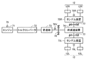
- FIG. 4 is a diagram schematically showing a configuration related to drive control of traveling wheels in the motor grader 1 based on the embodiment.
- the motor grader 1 of the embodiment is a rear wheel drive vehicle in which the driving force of the engine 71 is transmitted to the rear wheels 12 and the rear wheels 12 are used as the driving wheels.
- the engine 71 is supported by the rear frame 21.
- the rotation speed of the engine 71 is controlled by controlling the amount of fuel supplied to the engine 71 according to the operation of the accelerator pedal 36 by the operator.
- the rotation speed of the engine 71 is detected by the engine rotation speed sensor 79.
- the power transmission devices for transmitting the driving force from the engine 71 to the rear wheels 12 include a torque converter 72, a transmission 73, a final deceleration device 74, and tandem devices 75L and 75R. have.
- the torque converter 72 is connected to the output side of the engine 71.
- the torque converter 72 is a fluid clutch that transmits a driving force from the engine 71 using oil as a medium.
- the torque converter 72 may be provided with a lockup clutch that directly connects the input side and the output side of the torque converter 72. Depending on the operator's choice, the transmission of power may be switched between the fluid clutch and the lockup clutch.
- the transmission 73 has a plurality of clutches corresponding to a plurality of speed stages. By switching between the engaged state and the disengaged state of each clutch, the transmission 73 can switch the reduction ratio in a plurality of stages.
- a speed sensor 76V is provided on the output shaft of the transmission 73. The speed sensor 76V detects the rotation speed of the output shaft of the transmission 73.
- the final deceleration device 74 is connected to the output shaft of the transmission 73.
- the driving force output from the transmission 73 is transmitted to the left and right tandem devices 75L and 75R via the final deceleration device 74.
- a pair of left rear wheels 12L are connected to the left tandem device 75L.
- a pair of right rear wheels 12R are connected to the right tandem device 75R.
- the engine 71 rotationally drives the left rear wheel 12L and the right rear wheel 12R via a torque converter 72, a transmission 73, a final deceleration device 74, and tandem devices 75L and 75R.
- the rotation speed sensor 76L detects the rotation speed of the left rear wheel 12L.
- the rotation speed sensor 76L measures the rotation speed of the left rear wheel 12L, for example, by measuring the rotation speed of the rotation shaft in the tandem device 75L.
- the rotation speed sensor 76R detects the rotation speed of the right rear wheel 12R.
- the rotation speed sensor 76R measures the rotation speed of the right rear wheel 12R, for example, by measuring the rotation speed of the rotation shaft in the tandem device 75R.
- a parking brake 78 is provided on the output shaft of the transmission 73.
- the parking brake is a brake used to maintain the running stop state of the motor grader 1.
- the parking brake 78 is, for example, a negative type brake.
- the operator operates the parking brake switch arranged in the cab 3 to switch between the braking state and the non-braking state of the parking brake 78.
- the parking brake switch may be provided on the right console 32R.
- the parking brake switch may be located behind the work equipment lever 35R.
- a service brake 77 driven by the operation of the brake pedal 37 by the operator is provided between the final deceleration device 74 and the tandem devices 75L and 75R.
- the service brake 77 is a brake used to reduce the traveling speed while the motor grader 1 is traveling.
- the braking force of the service brake 77 can be adjusted according to the amount of operation of the brake pedal 37.
- the service brake 77 is, for example, a positive type brake.
- FIG. 5 is a block diagram showing the system configuration of the motor grader 1.
- the motor grader 1 of the embodiment includes a controller 80.
- the controller 80 is a controller that controls the operation of the entire motor grader 1, and is composed of a CPU (Central Processing Unit), a non-volatile memory, a timer, and the like.
- CPU Central Processing Unit
- the steering operation lever 5 and the steering wheel 34 constituting the steering operation unit, the work machine levers 35L and 35R corresponding to the work machine operation unit, the accelerator pedal 36, and the brake pedal 37 are arranged in the cab 3. , Operated by the operator on board the cab 3. Sensors for detecting the operation direction and operation amount of each of the steering operation lever 5, the steering wheel 34, the work equipment levers 35L and 35R, the accelerator pedal 36, and the brake pedal 37 are provided. The detection signal detected by the sensor is input to the controller 80.
- the work equipment lock switch 61, the brake holding switch 62, and the parking brake switch 63 are arranged in the cab 3 and are operated by the operator boarding the cab 3.
- a sensor for detecting the operating state of each of the work equipment lock switch 61, the brake holding switch 62, and the parking brake switch 63 is provided. The detection signal detected by the sensor is input to the controller 80.
- the speed sensor 76V detects the moving speed (running speed of the motor grader 1) when the motor grader 1 is moving (running) by detecting the rotation speed of the output shaft of the transmission 73.
- the speed sensor 76V may detect the moving speed of the motor grader 1 by using, for example, GNSS (Global Navigation Satellite System).
- the rotation speed sensors 76L and 76R detect the rotation speeds of the left rear wheel 12L and the right rear wheel 12R, respectively.
- the engine rotation speed sensor 79 detects the rotation speed of the engine 71.
- the detection signals detected by the speed sensor 76V, the rotation speed sensors 76L, 76R and the engine rotation speed sensor 79 are input to the controller 80.
- the controller 80 has a brake control unit 82.
- the brake control unit 82 executes automatic brake holding control.
- a threshold value related to the traveling speed of the motor grader 1 is stored in the memory.
- the traveling speed of the motor grader 1 becomes equal to or less than the threshold value by the operation of the brake pedal 37 by the operator in a state where the brake holding switch 62 is operated to enable the automatic brake holding function.
- the braking force is maintained to maintain the running stop state of the motor grader 1.
- the brake control unit 82 releases the holding of the braking force.
- the controller 80 has an invalidation unit 84.
- the invalidation unit 84 determines whether or not the motor grader 1 is being operated by the working machine 4.
- the invalidation unit 84 invalidates the automatic brake holding control when the motor grader 1 is working by the work machine 4.
- the controller 80 sets various hydraulic actuators, specifically, lift cylinders 44, 45, drawbar shift cylinder 46, tilt cylinder 48, and swivel motor 49 according to the operation of the work machine operation unit (work machine lever 35L, 35R) by the operator. Outputs the control signal to operate. By controlling the hydraulic actuator, the operation of the working machine 4 is controlled.
- the motor grader 1 includes a hydraulic pump (not shown) driven by the driving force of the engine 71 and a main valve (not shown), and various hydraulic oils discharged from the hydraulic pump are supplied via the main valve. It is configured to be supplied to the hydraulic actuator of.
- the main valve is a spool type valve that adjusts the amount of hydraulic oil supplied to the hydraulic actuator by moving a rod-shaped spool in the axial direction.
- the controller 80 transmits a control signal for moving the spool of the main valve to the main valve. This controls the operation of various hydraulic actuators.
- the controller 80 also outputs a control signal for locking the work machine 4 according to the operation of the work machine lock switch 61 by the operator.
- the controller 80 stops the spool of the main valve and controls so that the amount of hydraulic oil supplied to the hydraulic actuator does not fluctuate, so that the work machine 4 does not operate even if the operator operates the work machine levers 35L and 35R. Locked.
- the controller 80 transmits a control signal according to the operation of the steering operation unit and the accelerator pedal 36 by the operator to the engine 71 and the transmission 73.
- the traveling operation of the motor grader 1 is controlled.
- the controller 80 transmits a control signal according to the operation of the parking brake switch 63 by the operator to the parking brake 78.
- the motor grader 1 is maintained in the running stop state, or the motor grader 1 is in a running state.
- the controller 80 transmits a control signal according to the operation of the brake pedal 37 by the operator to the service brake 77.
- the service brake 77 is activated, the traveling speed of the motor grader 1 is reduced.
- the controller 80 transmits a control signal to the notification unit 90.
- the notification unit 90 notifies the operator of information regarding the operating state of the motor grader 1.
- the notification unit 90 may include, for example, a work machine lock indicator light that lights up when the work machine 4 is locked by the operation of the work machine lock switch 61 and turns off when the work machine 4 is unlocked.
- the notification unit 90 may include, for example, an automatic brake holding indicator light that lights up when the automatic brake holding function is enabled and turns off when the automatic brake holding function is disabled by operating the brake holding switch 62.
- the work machine lock indicator light and the automatic brake hold indicator light may be provided on the work machine lock switch 61 and the brake hold switch 62, respectively.
- the notification unit 90 may include a monitor, and the work equipment lock indicator light and the automatic brake holding indicator light may be displayed on the monitor. It may pop up on the monitor when the work equipment lock indicator and the automatic brake hold indicator are on.
- the monitor may display vehicle body information such as the traveling speed of the motor grader 1, the remaining amount of fuel, and the hydraulic oil temperature.
- vehicle body information such as the traveling speed of the motor grader 1, the remaining amount of fuel, and the hydraulic oil temperature.
- an image pickup device such as a rear view camera for viewing the rear of the vehicle body
- the image captured by the image pickup device may be displayed on the monitor.
- FIG. 6 is a schematic diagram showing an example of a control logic for switching ON and OFF of the automatic brake holding function.
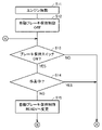
- FIG. 7 is a flow chart showing a processing flow in a state where the automatic brake holding control is OFF.
- step S11 When the engine 71 is started (step S11), the automatic brake holding control is turned off (step S12). In the state where the automatic brake holding control is OFF, the controller 80 determines whether or not the first condition is satisfied.
- the first condition is that the brake holding switch 62 is turned on and that the work machine 4 is not working, all of which are satisfied. It can be said that the fact that the first condition is satisfied indicates the operator's intention to enable the automatic brake holding function and not to work with the work machine 4. If the brake holding switch 62 is ON (YES in step S13) and the work by the working machine 4 is not in progress (NO in step S14), the first condition is satisfied and the automatic brake holding control is automatically turned off. The state is changed to the brake holding control READY state (step S15).
- the controller 80 may determine, for example, whether or not the work is being performed by the work machine 4 based on the operating state of the work machine lock switch 61. Specifically, since the working machine 4 is locked during the forwarding running of the motor grader 1, if the working machine lock switch 61 is turned on and the working machine 4 is in the locked state, it is not during work but during running. If it is determined that there is, the work machine lock switch 61 is turned off, and the work machine 4 is unlocked, it may be determined that the work is in progress.
- the controller 80 may determine, for example, whether or not the work is being performed by the work machine 4 based on the operation state of the work machine operation unit (work machine levers 35L, 35R). Since the operator operates the work machine levers 35L and 35R during work, if an electric signal indicating that one or more work machine levers 35L and 35R are being operated is input to the controller 80, It may be determined that the work is in progress. A touch sensor for detecting that the operator is touching the work equipment levers 35L and 35R is provided, and if the touch sensor detects that the operator is touching the work equipment levers 35L and 35R, it is determined that the work is in progress. You may.
- the controller 80 may determine whether or not the work is being performed by the work machine 4 based on the operation state of the steering operation unit in addition to the operation state of the work machine levers 35L and 35R. For example, an electric signal indicating that the operator does not operate the work equipment levers 35L and 35R for a certain period of time (60 seconds as an example) and that the steering operation unit is operated after the certain time has elapsed is transmitted to the controller 80. If it is input, it may be determined that the work is not in progress.
- step S13 If the brake holding switch 62 is OFF (NO in step S13) or the work is being performed by the working machine 4 (YES in step S14), the first condition is not satisfied, and the determination in step S13 is returned to automatic.
- the brake holding control is left in the OFF state.
- FIG. 8 is a flow chart showing a processing flow in the state of automatic brake holding control READY.
- the automatic brake holding control READY state is a control for maintaining the running stopped state of the motor grader 1 because the condition related to the work and the condition related to the brake holding switch 62 are satisfied but the motor grader 1 has not stopped running. Although it has not been executed, it can be said that the control for maintaining the traveling stopped state of the motor grader 1 can be executed immediately when the motor grader 1 stops traveling.
- the controller 80 In the state of the automatic brake holding control READY, the controller 80 first determines whether or not the second condition is satisfied.
- the second condition is that either the brake holding switch 62 is turned off or the work machine 4 is working. It can be said that the satisfaction of the second condition indicates the operator's intention to release the brake holding function by any operation of the operator. If the brake holding switch 62 is OFF (YES in step S21) or the work is being performed by the working machine 4 (YES in step S22), the second condition is satisfied, and the automatic brake holding control READY state is set. The state shifts to the state where the automatic brake holding control is OFF (step S23), and the automatic brake holding control is canceled. When it is determined that the work is being performed by the work machine 4, the automatic brake holding control is invalidated.
- step S21 If the brake holding switch 62 is ON (NO in step S21) and the work by the working machine 4 is not in progress (NO in step S22), the second condition is not satisfied, and the controller 80 subsequently performs the third condition. Is determined whether or not is satisfied.
- the third condition is that the traveling speed of the motor grader 1 is determined to be equal to or less than a predetermined threshold value (1.0 km / h as an example) and the vehicle is stopped, and the operation of the brake pedal 37 is performed for a predetermined time (3 seconds as an example) or more. It is satisfied that it is continued and that the operation amount of the accelerator pedal 36 is equal to or less than a predetermined threshold value (0% as an example). It can be said that the satisfaction of the third condition indicates the intention of the operator to stop the running of the motor grader 1.
- the threshold value of the traveling speed may be 0 km / h, and the automatic brake holding control may be turned on only when the motor grader 1 is completely stopped.
- step S24 When the operator operates the brake pedal 37, the traveling speed becomes equal to or lower than the threshold value (YES in step S24), the operation time of the brake pedal 37 is continued for a predetermined time (YES in step S25), and the accelerator pedal 36 is operated. If the amount is equal to or less than the threshold value (YES in step S26), the third condition is satisfied, and the state of the automatic brake holding control READY is changed to the state of the automatic brake holding control ON (step S27).
- step S24 If the traveling speed is higher than the threshold value (NO in step S24), the operation time of the brake pedal 37 does not continue for a predetermined time (NO in step S25), or the operation amount of the accelerator pedal 36 is larger than the threshold value (NO in step S26). NO), the third condition is not satisfied, and the process returns to the determination in step S21, and the state of the automatic brake holding control READY remains.
- the controller 80 keeps the braking force and maintains the running stop state of the motor grader 1 by putting the parking brake 78 in the braking state or the service brake 77 in the braking state. .. At this time, the controller 80 may shift the transmission 73 to neutral in order to improve fuel efficiency and protect the brakes.
- the speed stage setting is displayed on the monitor, even if the setting of the transmission 73 is changed to neutral due to the automatic brake holding control, the display of the monitor remains unchanged and the original speed stage setting is displayed. You may do it.
- the brake light that lights up when the operator operates the brake pedal 37 may remain lit even if the operator takes his / her foot off the brake pedal 37. The operator may be notified that the automatic brake holding function is effective, such as by displaying it on a monitor.
- FIG. 9 is a flow chart showing a processing flow in a state where the automatic brake holding control is ON.
- the controller 80 first determines whether or not the second condition is satisfied.
- step S31 If the brake holding switch 62 is OFF (YES in step S31) or the work is being performed by the working machine 4 (YES in step S32), the second condition is satisfied and the automatic brake holding control is automatically turned on. The brake holding control is turned off, and the automatic brake holding control is canceled. If the brake holding switch 62 is ON (NO in step S31) and the work by the working machine 4 is not in progress (NO in step S32), the second condition is not satisfied, and the controller 80 subsequently performs the fourth condition. Is determined whether or not is satisfied.
- the fourth condition is that the brake holding switch 62 is turned on, that the work machine 4 is not working, and that the operation amount of the accelerator pedal 36 is equal to or more than a predetermined threshold value. Is. It can be said that the fact that the fourth condition is satisfied indicates the intention of the operator to drive the motor grader 1 while the automatic brake holding function is enabled. Of the three conditions included in the fourth condition, the fact that the work machine 4 is not working and that the brake holding switch 62 is turned on are conditions that are also included in the first condition.
- Step S34 the fourth condition is satisfied, and the state of the automatic brake holding control ON is changed to the state of the automatic brake holding control READY (YES in step S34).
- Step S35 That is, when the operator operates the accelerator pedal 36, the holding of the braking force is released, and the motor grader 1 is in a state in which the motor grader 1 can travel.
- step S27 When the controller 80 shifts the transmission 73 to neutral in step S27, the controller 80 is based on the transmission 73 when the fourth condition is satisfied and the automatic brake holding control READY state is entered. It returns to the speed stage setting of.
- step S34 If the operation amount of the accelerator pedal 36 is smaller than the threshold value (NO in step S34), the fourth condition is not satisfied, the judgment is returned to step S31, and the automatic brake holding control is left in the ON state.
- the controller 80 has a brake control unit 82 and an invalidation unit 84.
- the brake control unit 82 maintains the braking force when the traveling speed of the motor grader 1 becomes equal to or less than the threshold value by operating the brake pedal 37, maintains the traveling stopped state of the motor grader 1, and controls by operating the accelerator pedal 36. Executes automatic brake holding control to release the holding of power.
- the invalidation unit 84 determines whether or not the motor grader 1 is working by the working machine 4, and invalidates the automatic brake holding control when the motor grader 1 is working.
- the automatic brake holding control By applying the automatic brake holding control to the motor grader 1, the fatigue of the operator who operates the motor grader 1 can be reduced.
- the automatic brake holding control is disabled, so that the work while the motor grader 1 is traveling at a very low speed is not hindered. Therefore, the operability of the motor grader 1 can be improved.
- the motor grader 1 further includes a work machine lock switch 61 that limits the operation of the work machine 4.
- the controller 80 may determine whether or not the motor grader 1 is working by the working machine 4 based on the operating state of the working machine lock switch 61. Since the working machine 4 is locked during the forwarding running of the motor grader 1, if the working machine lock switch 61 is turned on and the working machine 4 is in the locked state, it is determined that the working machine 4 is running, not working. If the work machine lock switch 61 is turned off and the work machine 4 is unlocked, it may be determined that the work is in progress. Thereby, it is possible to accurately determine whether or not the motor grader 1 is working by the working machine 4.
- the motor grader 1 further includes working machine levers 35L and 35R for the operator to operate the working machine 4.
- the controller 80 may determine whether or not the motor grader 1 is working by the working machine 4 based on the operating state of the working machine levers 35L and 35R. Since the operator operates the work machine levers 35L and 35R during the work, if it is detected that the operator is operating the work machine levers 35L and 35R or the operator is touching the work machine levers 35L and 35R. , It may be determined that the work is in progress. Thereby, it is possible to accurately determine whether or not the motor grader 1 is working by the working machine 4.
- the motor grader 1 further includes a steering operation unit for the operator to operate the traveling direction of the motor grader 1.
- the controller 80 may determine whether or not the motor grader 1 is working by the working machine 4 based on the operating state of the steering operation unit. For example, it may be determined that the work is in progress when the frequency of operation of the steering wheel 34 within a predetermined period is significantly lower than the frequency of operation of the steering operation lever 5. Alternatively, if it is detected that the operator does not operate the work equipment levers 35L and 35R and the steering wheel 34 is operated, it may be determined that the work is not being performed but the vehicle is being forwarded. Thereby, it is possible to accurately determine whether or not the motor grader 1 is working by the working machine 4.
- the motor grader 1 further includes a brake hold switch 62 operated to select a setting for enabling automatic brake hold control. As shown in FIG. 9, whether or not the motor grader 1 is being operated by the working machine 4 in a state where the controller 80 is set to enable the automatic brake holding control by operating the brake holding switch 62. Is determined, and when it is determined that the work is not in progress, the automatic brake holding control is executed. As a result, the automatic brake holding function can be used without affecting the work of the motor grader 1.
- any other means may be applied, such as enabling or disabling the automatic brake holding function by operating a monitor as a touch panel.
- the operation lever for the operator to operate the work machine 4 may be a hydraulic lever.
- the operating state of the lever can be determined by detecting with the pressure sensor that the hydraulic pressure fluctuates due to the operation of the lever. Based on the result of the determination, it may be determined whether or not the work is being performed by the working machine 4.
- the power transmission device for transmitting the driving force from the engine 71 to the rear wheels 12 has a mechanical transmission 73 .
- the power transmission device generates pressure oil by driving a hydraulic pump with the engine 71, and the hydraulic motor is driven by the pressure oil discharged from the hydraulic pump to generate rotational force again.
- HST Hydrophilic Static Transmission
- the motor grader 1 is not limited to the rear-wheel drive vehicle, but may be an all-wheel drive vehicle.
- the power transmission device from the engine 71 to the rear wheels 12 may have a mechanical transmission 73 or an HST.
- the power transmission device from the engine 71 to the front wheels 11 may have an HST.
- the motor grader 1 is mentioned as an example of the work machine, but the motor grader 1 is not limited to the motor grader 1, and it can be applied to other types of work machines such as wheel loaders that work while running. Further, the idea of the embodiment may be applied to other drive systems such as a diesel electric vehicle in which a generator is driven by an engine, a battery-powered electric vehicle (BEV), and a fuel cell-powered vehicle (FCV).
- BEV battery-powered electric vehicle
- FCV fuel cell-powered vehicle
Landscapes
- Engineering & Computer Science (AREA)
- Mining & Mineral Resources (AREA)
- Civil Engineering (AREA)
- General Engineering & Computer Science (AREA)
- Structural Engineering (AREA)
- Mechanical Engineering (AREA)
- Transportation (AREA)
- Regulating Braking Force (AREA)
- Operation Control Of Excavators (AREA)
Abstract
Description
Claims (7)
- 走行する車体と、
前記車体に支持された作業機と、
前記車体の走行速度を増加するために操作されるアクセル操作装置と、
前記車体の走行速度を減少するために操作されるブレーキ操作装置と、
コントローラとを備え、
前記コントローラは、
前記ブレーキ操作装置の操作により前記車体の走行速度が閾値以下となったときに制動力を保持して前記車体の走行停止状態を維持し、前記アクセル操作装置の操作により制動力の保持を解除する、自動ブレーキ保持制御を実行し、
前記作業機による作業中であるか否かを判別し、作業中の場合には前記自動ブレーキ保持制御を無効とする、
作業機械。 - 前記作業機の動作を制限する作業機ロック装置をさらに備え、
前記コントローラは、前記作業機ロック装置の操作状態に基づいて作業中であるか否かを判別する、請求項1に記載の作業機械。 - オペレータが前記作業機を操作するための作業機操作部をさらに備え、
前記コントローラは、前記作業機操作部の操作状態に基づいて作業中であるか否かを判別する、請求項1に記載の作業機械。 - オペレータが前記車体の走行方向を操作するためのステアリング操作部をさらに備え、
前記コントローラは、前記ステアリング操作部の操作状態に基づいて作業中であるか否かを判別する、請求項3に記載の作業機械。 - 前記自動ブレーキ保持制御を有効にする設定を選択するために操作されるスイッチをさらに備え、
前記コントローラは、前記スイッチの操作により前記自動ブレーキ保持制御を有効にする設定がされている状態で、前記作業機による作業中でないと判別した場合に、前記自動ブレーキ保持制御を実行する、請求項1から請求項4のいずれか1項に記載の作業機械。 - 走行する車体と、
前記車体に支持された作業機と、
前記車体の走行速度を増加するために操作されるアクセル操作装置と、
前記車体の走行速度を減少するために操作されるブレーキ操作装置と、
を備える作業機械の制御装置であって、
前記ブレーキ操作装置の操作により前記車体の走行速度が閾値以下となったときに制動力を保持して前記車体の走行停止状態を維持し、前記アクセル操作装置の操作により制動力の保持を解除する、自動ブレーキ保持制御を実行し、
前記作業機による作業中であるか否かを判別し、作業中の場合には前記自動ブレーキ保持制御を無効とする、作業機械の制御装置。 - 走行する車体と、
前記車体に支持された作業機と、
前記車体の走行速度を増加するために操作されるアクセル操作装置と、
前記車体の走行速度を減少するために操作されるブレーキ操作装置と、
を備える作業機械の制御方法であって、
前記ブレーキ操作装置の操作により前記車体の走行速度が閾値以下となったときに制動力を保持して前記車体の走行停止状態を維持し、前記アクセル操作装置の操作により制動力の保持を解除する、自動ブレーキ保持制御を実行することと、
前記作業機による作業中であるか否かを判別し、作業中の場合には前記自動ブレーキ保持制御を無効とすることと、を備える、作業機械の制御方法。
Priority Applications (3)
| Application Number | Priority Date | Filing Date | Title |
|---|---|---|---|
| EP21903076.4A EP4206406A4 (en) | 2020-12-10 | 2021-11-05 | WORKING MACHINE, DEVICE FOR CONTROLLING THE WORKING MACHINE AND METHOD FOR CONTROLLING THE WORKING MACHINE |
| CN202180071584.XA CN116368277A (zh) | 2020-12-10 | 2021-11-05 | 作业机械、作业机械的控制装置以及作业机械的控制方法 |
| US18/036,448 US12590441B2 (en) | 2020-12-10 | 2021-11-05 | Work machine, controller for work machine, and method of controlling work machine |
Applications Claiming Priority (2)
| Application Number | Priority Date | Filing Date | Title |
|---|---|---|---|
| JP2020-204927 | 2020-12-10 | ||
| JP2020204927A JP7504012B2 (ja) | 2020-12-10 | 2020-12-10 | 作業機械、作業機械の制御装置、および作業機械の制御方法 |
Publications (1)
| Publication Number | Publication Date |
|---|---|
| WO2022123972A1 true WO2022123972A1 (ja) | 2022-06-16 |
Family
ID=81973662
Family Applications (1)
| Application Number | Title | Priority Date | Filing Date |
|---|---|---|---|
| PCT/JP2021/040694 Ceased WO2022123972A1 (ja) | 2020-12-10 | 2021-11-05 | 作業機械、作業機械の制御装置、および作業機械の制御方法 |
Country Status (5)
| Country | Link |
|---|---|
| US (1) | US12590441B2 (ja) |
| EP (1) | EP4206406A4 (ja) |
| JP (1) | JP7504012B2 (ja) |
| CN (1) | CN116368277A (ja) |
| WO (1) | WO2022123972A1 (ja) |
Families Citing this family (2)
| Publication number | Priority date | Publication date | Assignee | Title |
|---|---|---|---|---|
| US12359396B2 (en) * | 2021-07-16 | 2025-07-15 | Caterpillar Inc. | Damage avoidance systems and methods for motor grader scarifiers |
| WO2025205826A1 (ja) * | 2024-03-26 | 2025-10-02 | 株式会社小松製作所 | 作業機械、作業機械のシステムおよび作業機械の制御方法 |
Citations (5)
| Publication number | Priority date | Publication date | Assignee | Title |
|---|---|---|---|---|
| JPH08142819A (ja) * | 1994-11-22 | 1996-06-04 | Fujitsu Ten Ltd | ブレーキホールド制御装置 |
| JPH09142270A (ja) * | 1995-11-22 | 1997-06-03 | Honda Motor Co Ltd | 車両の制動力保持装置 |
| JP2000033859A (ja) | 1998-07-17 | 2000-02-02 | Mitsubishi Electric Corp | 停車ブレーキ装置 |
| JP2001341624A (ja) * | 2000-06-05 | 2001-12-11 | Mitsubishi Electric Corp | 停車ブレーキ装置 |
| JP2005299102A (ja) * | 2004-04-07 | 2005-10-27 | Kobelco Contstruction Machinery Ltd | 旋回式作業機械 |
Family Cites Families (12)
| Publication number | Priority date | Publication date | Assignee | Title |
|---|---|---|---|---|
| JPS6092117A (ja) | 1983-10-26 | 1985-05-23 | Fujitsu Ten Ltd | 自動車の制動装置 |
| JP2003184808A (ja) | 2001-12-14 | 2003-07-03 | Hitachi Constr Mach Co Ltd | 旋回用駐車ブレーキ油圧回路 |
| JP3977697B2 (ja) | 2002-07-05 | 2007-09-19 | コベルコ建機株式会社 | 作業機械の旋回制御装置 |
| KR100674516B1 (ko) | 2002-05-09 | 2007-01-26 | 코벨코 겐키 가부시키가이샤 | 작업 기계의 선회 제어 장치 |
| WO2005007472A1 (en) * | 2003-07-08 | 2005-01-27 | Orscheln Products Llc | Pedal assembly |
| JP4846359B2 (ja) * | 2005-12-22 | 2011-12-28 | 株式会社小松製作所 | 作業車両の制御装置 |
| JP5079424B2 (ja) * | 2007-08-27 | 2012-11-21 | アルパイン株式会社 | 車載機器制御装置及び車載機器制御方法 |
| KR101523279B1 (ko) * | 2011-03-30 | 2015-05-27 | 스미토모 겐키 가부시키가이샤 | 쇼벨 |
| JP5705755B2 (ja) * | 2012-01-19 | 2015-04-22 | 日立建機株式会社 | 作業機械の油圧制御装置 |
| JP5092059B1 (ja) * | 2012-03-29 | 2012-12-05 | 株式会社小松製作所 | 作業車両及び作業車両の制御方法 |
| JP6495729B2 (ja) | 2015-04-28 | 2019-04-03 | 日立建機株式会社 | 建設機械の制御装置 |
| JP2019002233A (ja) | 2017-06-19 | 2019-01-10 | 株式会社小松製作所 | モータグレーダ |
-
2020
- 2020-12-10 JP JP2020204927A patent/JP7504012B2/ja active Active
-
2021
- 2021-11-05 EP EP21903076.4A patent/EP4206406A4/en not_active Withdrawn
- 2021-11-05 CN CN202180071584.XA patent/CN116368277A/zh active Pending
- 2021-11-05 US US18/036,448 patent/US12590441B2/en active Active
- 2021-11-05 WO PCT/JP2021/040694 patent/WO2022123972A1/ja not_active Ceased
Patent Citations (5)
| Publication number | Priority date | Publication date | Assignee | Title |
|---|---|---|---|---|
| JPH08142819A (ja) * | 1994-11-22 | 1996-06-04 | Fujitsu Ten Ltd | ブレーキホールド制御装置 |
| JPH09142270A (ja) * | 1995-11-22 | 1997-06-03 | Honda Motor Co Ltd | 車両の制動力保持装置 |
| JP2000033859A (ja) | 1998-07-17 | 2000-02-02 | Mitsubishi Electric Corp | 停車ブレーキ装置 |
| JP2001341624A (ja) * | 2000-06-05 | 2001-12-11 | Mitsubishi Electric Corp | 停車ブレーキ装置 |
| JP2005299102A (ja) * | 2004-04-07 | 2005-10-27 | Kobelco Contstruction Machinery Ltd | 旋回式作業機械 |
Non-Patent Citations (1)
| Title |
|---|
| See also references of EP4206406A4 |
Also Published As
| Publication number | Publication date |
|---|---|
| JP2022092241A (ja) | 2022-06-22 |
| US12590441B2 (en) | 2026-03-31 |
| US20230417021A1 (en) | 2023-12-28 |
| CN116368277A (zh) | 2023-06-30 |
| EP4206406A1 (en) | 2023-07-05 |
| JP7504012B2 (ja) | 2024-06-21 |
| EP4206406A4 (en) | 2024-10-23 |
Similar Documents
| Publication | Publication Date | Title |
|---|---|---|
| WO2022176991A1 (ja) | 作業機械の制御システム、作業機械の制御方法、および作業機械 | |
| JP5705755B2 (ja) | 作業機械の油圧制御装置 | |
| JP7490127B2 (ja) | モータグレーダおよび表示制御方法 | |
| WO2022123972A1 (ja) | 作業機械、作業機械の制御装置、および作業機械の制御方法 | |
| JP6670268B2 (ja) | トラクタ | |
| JP6577433B2 (ja) | ホイール式油圧ショベル | |
| US11794577B2 (en) | Work machine and control method thereof | |
| JP2019206873A (ja) | ホイール式作業機械 | |
| JP4361422B2 (ja) | 作業車両 | |
| JP2021024293A (ja) | 作業車両 | |
| JP2009083612A (ja) | 作業車 | |
| CN105189155B (zh) | 用于操作移动式挖掘机的行车制动器并锁定其摆动轴的装置 | |
| JP5070788B2 (ja) | 作業車 | |
| JP4996429B2 (ja) | 作業車両の独立型サスペンション | |
| CN116867944B (zh) | 工程机械的控制系统、工程机械的控制方法、及工程机械 | |
| JP6852257B2 (ja) | 作業車両 | |
| JP7794657B2 (ja) | ホイール式作業車両 | |
| JP4730551B2 (ja) | 作業車両 | |
| JP2003095599A (ja) | 作業用車両の安全装置 | |
| JP4354890B2 (ja) | 作業車両の操向装置 | |
| JP2022095411A (ja) | 作業車の走行制御装置 | |
| JP2008082124A (ja) | トラクタ | |
| WO2024128214A1 (ja) | 作業機械、作業機械の制動システムおよび作業機械の制御方法 | |
| JP2022047169A (ja) | 乗用型農作業車 | |
| JP2021116905A (ja) | 作業車両 |
Legal Events
| Date | Code | Title | Description |
|---|---|---|---|
| 121 | Ep: the epo has been informed by wipo that ep was designated in this application |
Ref document number: 21903076 Country of ref document: EP Kind code of ref document: A1 |
|
| ENP | Entry into the national phase |
Ref document number: 2021903076 Country of ref document: EP Effective date: 20230328 |
|
| WWE | Wipo information: entry into national phase |
Ref document number: 18036448 Country of ref document: US |
|
| NENP | Non-entry into the national phase |
Ref country code: DE |
|
| WWG | Wipo information: grant in national office |
Ref document number: 18036448 Country of ref document: US |