WO2022126335A1 - Adjustment mechanism for circuit breaker and corresponding circuit breaker - Google Patents
Adjustment mechanism for circuit breaker and corresponding circuit breaker Download PDFInfo
- Publication number
- WO2022126335A1 WO2022126335A1 PCT/CN2020/136228 CN2020136228W WO2022126335A1 WO 2022126335 A1 WO2022126335 A1 WO 2022126335A1 CN 2020136228 W CN2020136228 W CN 2020136228W WO 2022126335 A1 WO2022126335 A1 WO 2022126335A1
- Authority
- WO
- WIPO (PCT)
- Prior art keywords
- linkage
- pin
- terminal
- adjustment mechanism
- circuit breaker
- Prior art date
- Legal status (The legal status is an assumption and is not a legal conclusion. Google has not performed a legal analysis and makes no representation as to the accuracy of the status listed.)
- Ceased
Links
Images




Classifications
-
- H—ELECTRICITY
- H01—ELECTRIC ELEMENTS
- H01H—ELECTRIC SWITCHES; RELAYS; SELECTORS; EMERGENCY PROTECTIVE DEVICES
- H01H83/00—Protective switches, e.g. circuit-breaking switches, or protective relays operated by abnormal electrical conditions otherwise than solely by excess current
- H01H83/02—Protective switches, e.g. circuit-breaking switches, or protective relays operated by abnormal electrical conditions otherwise than solely by excess current operated by earth fault currents
-
- H—ELECTRICITY
- H01—ELECTRIC ELEMENTS
- H01H—ELECTRIC SWITCHES; RELAYS; SELECTORS; EMERGENCY PROTECTIVE DEVICES
- H01H83/00—Protective switches, e.g. circuit-breaking switches, or protective relays operated by abnormal electrical conditions otherwise than solely by excess current
- H01H83/02—Protective switches, e.g. circuit-breaking switches, or protective relays operated by abnormal electrical conditions otherwise than solely by excess current operated by earth fault currents
- H01H83/04—Protective switches, e.g. circuit-breaking switches, or protective relays operated by abnormal electrical conditions otherwise than solely by excess current operated by earth fault currents with testing means for indicating the ability of the switch or relay to function properly
-
- H—ELECTRICITY
- H02—GENERATION; CONVERSION OR DISTRIBUTION OF ELECTRIC POWER
- H02B—BOARDS, SUBSTATIONS OR SWITCHING ARRANGEMENTS FOR THE SUPPLY OR DISTRIBUTION OF ELECTRIC POWER
- H02B11/00—Switchgear having carriage withdrawable for isolation
- H02B11/12—Switchgear having carriage withdrawable for isolation with isolation by horizontal withdrawal
- H02B11/127—Withdrawal mechanism
-
- H—ELECTRICITY
- H01—ELECTRIC ELEMENTS
- H01H—ELECTRIC SWITCHES; RELAYS; SELECTORS; EMERGENCY PROTECTIVE DEVICES
- H01H71/00—Details of the protective switches or relays covered by groups H01H73/00 - H01H83/00
- H01H71/10—Operating or release mechanisms
Definitions
- Example embodiments of the present disclosure generally relate to the field of electrical equipment, and in particular, to an adjustment mechanism for a circuit breaker and the corresponding circuit breaker.
- a circuit breaker In the field of electrical equipment, a circuit breaker is typically connected to a main circuit so as to cut off the main circuit when the current in the circuit exceeds a threshold.
- the conventional circuit breaker only has two operating positions, i.e., a connection position and a disconnection position.
- the conventional circuit breaker does not have a test position at which a test of the circuit breaker can be carried out to reflect an overall operating state of the circuit breaker.
- the circuit breaker needs to be pulled out for maintenance on a regular basis. Since there is no test position, the conventional circuit breaker must include an additional test circuit to carry out the test operation. When the circuit breaker is pulled out, terminals of the test circuit would have to be pulled out as well, which brings inconvenience to the maintenance work.
- how to add a test position for the circuit breaker and switch the circuit breaker among the test position, the connection position and the disconnection position in a straightforward manner remains a challenge.
- example embodiments of the present disclosure provide a solution for switching the circuit breaker among the test position, the connection position and the disconnection position conveniently.
- an adjustment mechanism for a circuit breaker comprises a pin adapted to move with respect to a base part of the circuit breaker along a predefined path; a first linkage coupled to the base part and adapted to drive a first terminal of the circuit breaker to move towards or away from the base part, the first linkage comprising a groove in which the pin moves; and a second linkage coupled to a second terminal of the circuit breaker and adapted to be actuated by the pin to drive the second terminal to move towards or away from the base part, the groove comprises a first segment; and the second linkage is actuated by the pin and the first linkage is not actuated by the pin when the pin moves within the first segment in a first direction along the predefined path.
- the groove further comprises a second segment in communication with the first segment; and the first linkage is actuated by the pin and the second linkage is not actuated by the pin when the pin moves within the second segment in the first direction along the predefined path.
- the first terminal is arranged on a frame and the second terminal is arranged on a terminal support; and the second linkage is hinged to the terminal support.
- the adjustment mechanism further comprises a third linkage coupled to the frame at one end and hinged to the second linkage at the other end.
- the terminal support comprises a bending part along which the pin moves in a second direction opposite to the first direction; and the first linkage is actuated by the pin and the second linkage is not actuated by the pin when the pin moves along the bending part in the second direction.
- the adjustment mechanism further comprises a fourth linkage hinged to the base part at one end, and a fifth linkage hinged to the fourth linkage at one end and hinged to the first linkage at the other end, when the pin moves within the second segment in the first direction along the predefined path, the first linkage drives the fifth linkage to cause the fourth linkage to rotate with respect to the base part.
- the fourth linkage and the fifth linkage are hinged to each other by a lever
- the frame comprises two hooks coupled to both ends of the lever respectively, and when the first linkage moves, the fifth linkage 205 is actuated, such that the lever moves to actuate the frame to move towards or away from the base part.
- the second linkage comprises a protrusion, and when the pin moves within the first segment in the first direction along the predefined path, the pin pushes the protrusion to actuate the second linkage.
- the first linkage further comprises a recessed part between the first and second segments, when the pin moves to an end position in the first direction along the predefined path, the recessed part provides a space for accommodating the pin.
- the frame further comprises a protruding part;
- the adjustment mechanism further comprises an indicating part adjacent to the protruding part configured to indicate whether the hook is coupled to the lever; and when the hook is coupled to the lever, the protruding part detaches from the indicating part.
- the pin is provided at an end face of a worm gear meshed to a worm.
- the adjustment mechanism further comprises a stop nut provided at the worm and adapted to limit the range of movement of the worm.
- the pin is provided at an end face of a worm gear meshed to a worm and the first linkage, the worm gear and the fifth linkage are arranged such that when the pin moves to an end position of the first segment in the first direction along the predefined path, the fifth linkage is provided approximately tangent to the worm gear.
- the first terminal is a terminal for electrical connection
- the second terminal is a terminal for testing.
- a circuit breaker In a second aspect, a circuit breaker is provided.
- the circuit breaker comprises an adjustment mechanism of the first aspect.
- Figs. 1A-1C illustrate different adjustment stages of the circuit breaker in accordance with an example embodiment of the present disclosure
- Figs. 2A-2D illustrate different adjustment stages of the adjustment mechanism in accordance with an example embodiment of the present disclosure
- Figs. 3A-3D illustrate different adjustment stages for the first terminal in accordance with an example embodiment of the present disclosure
- Fig. 4 illustrates a perspective view of a first linkage in accordance with an example embodiment of the present disclosure
- Fig. 5 illustrates a perspective view of the first and terminal supports in accordance with an example embodiment of the present disclosure
- Fig. 6 illustrates a perspective view of the terminal support in accordance with an example embodiment of the present disclosure, which shows a bending part
- Fig. 7 illustrates an explosive view of components of the adjustment mechanism for adjusting the first terminal in accordance with an example embodiment of the present disclosure.
- Fig. 8 illustrates an indicating part in accordance with an example embodiment of the present disclosure.
- references in the present disclosure to “one embodiment, ” “an embodiment, ” “an example embodiment, ” and the like indicate that the embodiment described may include a particular feature, structure, or characteristic, but it is not necessary that every embodiment includes the particular feature, structure, or characteristic. Moreover, such phrases are not necessarily referring to the same embodiment. Further, when a particular feature, structure, or characteristic is described in connection with an embodiment, it is submitted that it is within the knowledge of one skilled in the art to apply such feature, structure, or characteristic in connection with other embodiments whether or not explicitly described.
- first and second etc. may be used herein to describe various elements, these elements should not be limited by these terms. These terms are only used to distinguish one element from another. For example, a first element could be termed a second element, and similarly, a second element could be termed a first element, without departing from the scope of example embodiments. As used herein, the term “and/or” includes any and all combinations of one or more of the listed terms.
- the existing circuit breaker does not have a test position at which a test of the circuit breaker can be carried out to reflect an overall operating state of the circuit breaker, which brings great inconvenience for the user.
- a test position is provided in the circuit breaker.
- the circuit breaker When the user operates the circuit breaker with a tool, the circuit breaker will be first put into the test position. Then, if the user further operates the circuit breaker with the tool, the circuit breaker will be further put into a connection position. In this way, the user can operate the circuit breaker in a straightforward manner without the need of altering the operating manner.
- Figs. 1A-1C illustrate different adjustment stages of the circuit breaker 1 in accordance with an example embodiment of the present disclosure.
- the circuit breaker 1 as illustrated generally includes a base part 100, a first terminal 34 and a second terminal 36.
- the first terminal 34 may be a terminal for electrical connection.
- the second terminal 36 may be a terminal for testing.
- the first terminal 34 is adapted to move towards the base part 100 along a sliding direction L to establish an electrical connection between the first terminal 34 and the base part 100.
- the first terminal 34 is also adapted to move away from the base part 100 in a direction opposite to the sliding direction L so as to be disconnected from the base part 100.
- the second terminal 36 is adapted to move towards the base part 100 along the sliding direction L to establish an electrical connection for testing between the second terminal 36 and the base part 100.
- the second terminal 36 is also adapted to move away from the base part 100 in the direction opposite to the sliding direction L so as to be disconnected from the base part 100.
- Fig. 1A illustrates that both the first and second terminals 34, 36 are disconnected from the base part 100.
- the circuit breaker 1 as illustrated is in a disconnection position.
- the first and second terminals 34, 36 can be moved to different working positions, as illustrated in Figs. 1B-1C.
- Fig. 1B the second terminal 36 is connected to the base part 100, and the first terminal 34 is disconnected from the base part 100.
- both the first and second terminals 34, 36 are connected to the base part 100.
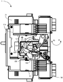
- Figs. 2A-2D illustrate different adjustment stages of an adjustment mechanism 10 in accordance with an example embodiment of the present disclosure.
- the adjustment mechanism 10 generally includes a pin 102, a first linkage 104 and a second linkage 106.
- the pin 102 can move with respect to the base part 100 of the circuit breaker 1 along a predefined path.
- the first linkage 104 is coupled to the base part 100 and can drive the first terminal 34 of the circuit breaker 1 to move towards or away from the base part 100.
- the second linkage 106 is coupled to the second terminal 36 of the circuit breaker 1 and can be actuated by the pin 102 to drive the second terminal 36 to move towards or away from the base part 100.
- the specific adjustment stages of the adjustment mechanism 10 would be described in detail hereinafter.
- Figs. 3A-3D illustrate different adjustment stages for the first terminal 34 in accordance with an example embodiment of the present disclosure.
- Figs. 3A-3C generally correspond to Figs. 2A-2C.
- the second linkage 106 is omitted so as to clearly illustrate the operation of the first linkage 104 and other components of the adjustment mechanism 10.
- Fig. 4 illustrates a perspective view of the first linkage 104 in accordance with an example embodiment of the present disclosure.
- the first linkage 104 includes a groove 105.
- the pin 102 is adapted to move in the groove 105.
- the groove 105 includes a first segment 1051.
- both the first and second terminals 34, 36 are disconnected from the base part 100. That is, the circuit breaker 1 is in the disconnection position.
- the pin 102 moves within the first segment 1051 in a first direction R1 along the predefined path, the pin 102 pushes the second linkage 106 to move.
- the pin 102 moves along the first direction R1 within the first segment 1051 to a position illustrated in Fig. 2B.
- the second terminal 36 is connected to the base part 100, and the first terminal 34 is disconnected from the base part 100. That is, the adjustment mechanism 10 is in a test position.
- the shape of the first segment 1051 of the groove 105 of the first linkage 104 is designed to be consistent with a part of the predefined path of the pin 102.
- the first segment 1051 may have a generally circular profile. It is to be understood that this is merely an example, without suggesting any limitation as to the scope of the disclosure.
- the first linkage 104 is not actuated by the pin 102 when the pin 102 moves within the first segment 1051 in the first direction R1.
- the second terminal 36 will be actuated to move towards the base part 100 while the first terminal 34 will not be actuated to move towards the base part 100.
- the connection between the second terminal 36 and the base part 100 will first be established while the first terminal 34 and the base part 100 are still kept disconnected.
- the test position is added to the circuit breaker 1 to allow the circuit breaker 1 to carry out a test operation prior to establishing the electrical connection. Since the users are allowed to inspect and repair the second terminal 36 at the test position when the first terminal 34 is disconnected from the base part 100, the maintenance of the second terminal 36 can be carried out in a convenient and safe manner for the users.
- the first terminal 34 is a terminal for electrical connection and the second terminal 36 is a terminal for test
- the maintenance of a test circuit formed by the terminal for testing can be carried out conveniently and safely.
- the groove 105 may further include a second segment 1052 in communication with the first segment 1051.
- the pin 102 may be actuated to further move to a position illustrated in Figs. 2C and 3C within the second segment 1052 along the predefined path in the first direction R1. Since the pin 102 starts to detach from the second linkage 106, as illustrated in Fig. 2B, the further movement of the pin 102 along the first direction will not exert a force on the second linkage 106. As a result, the second terminal 36 is kept in contact with the base part 100, as illustrated.
- both the first and second terminals 34, 36 are connected to the base part 100. That is, the adjustment mechanism 10 is in a connection position.
- the shape of the second segment 1052 may be designed to be inconsistent with the predefined path of the pin 102.
- the second segment 1052 may have a generally straight profile. It is to be understood that this is merely an example, without suggesting any limitation as to the scope of the disclosure.
- the second terminal 36 when actuating the pin 102 in the first direction R1, the second terminal 36 will be first actuated towards the base part 100 to connect to the base part 100 while the first terminal 34 remains disconnected from the base part 100. As the pin 102 moves further in the first direction R1, the first terminal 34 starts to be actuated towards base part 100 to connect to the base part 100 while the second terminal 36 remains connected to the base part 100.
- the movements of the first and second terminals 34, 36 would not interfere with each other. Moreover, since the first terminal 34 is locked when actuating the second terminal 36, the operation of the first terminal 34 will not be affected by other external factors, e.g., the vibration of the circuit breaker 1. Likewise, the operation of the second terminal 36 will also not be affected.
- the first terminal 34 is arranged on a moving part of the circuit breaker 1, which is supported by a frame 304.
- the second terminal 36 is arranged on a terminal support 306.
- the movement of the frame 304 would drive the moving part and the first terminal 34 to move.
- the movement of the terminal support 306 would drive the second terminal 36 to move.
- Fig. 5 illustrates a perspective view of the frame 304 and terminal support 306 in accordance with an example embodiment of the present disclosure.
- the first terminal 34 (not shown in Fig. 5) may be provided on the moving part of the circuit breaker 1 and the second terminal 36 (not shown in Fig. 5) may be provided on the terminal support 306.
- Fig. 6 illustrates a perspective view of the terminal support 306 in accordance with an example embodiment of the present disclosure.
- the second linkage 106 may be hinged to the terminal support 306.
- the adjustment mechanism 10 may further include a third linkage 203.
- the third linkage 203 may be coupled to the frame 304 at one end and coupled to the second linkage 106 at the other end.
- the movement of the second linkage 106 can be controlled in a stable manner.
- the pin 102 moves along the predefined path discussed above but in a second direction R2 opposite to the first direction R1. Not all figures of the detaching process are shown for brevity.
- the movement of the pin 102 along the second segment 1052 in the second direction R2 is exemplarily illustrated in Fig. 3D.
- the movement of the pin 102 along the first segment 1051 in the second direction R2 is exemplarily illustrated in Fig. 2D.
- the terminal support 306 includes a bending part 3062. While the pin 102 moves to an end position of the predefined path along the first direction R1, the pin 102 is pushed at the highest position or an end position of the bending part 3062. Next, the pin 102 will be actuated along the second direction R2 to pull out the first terminal 34. When the pin 102 is actuated along the second direction R2, the pin 102 may move along the bending part 3062. Due to the contact between the pin 102 and the bending part 3062, the terminal support 306 is kept stationary and will not be actuated by the pin 102. As a result, the second terminal 36 will remain in contact with the base part 100.
- the pin 102 moves in the second segment 1052 of the first linkage 104. As illustrated in Fig. 2D, the movement of the pin 102 will cause the first linkage 104 to drive the first terminal 34 to move away from the base part 100. In other words, when the pin 102 moves along the bending part 3062 in the second direction R2, the first linkage 104 would be actuated by the pin 102 and the second linkage 106 would not be actuated by the pin 102. Accordingly, the movements of the first and second terminals 34, 36 do not interfere with each other. The risk of misoperation can thus be greatly reduced.
- the adjustment mechanism 10 may further include a fourth linkage 204 and a fifth linkage 205.
- the fourth linkage 204 may be hinged to the base part 100 at one end.
- the fifth linkage 205 may be hinged to the fourth linkage 204 at one end and hinged to the first linkage 104 at the other end. While the pin 102 moves within the second segment 1052 along the predefined path, the first linkage 104 drives the fifth linkage 205 to cause the fourth linkage 204 to rotate with respect to the base part 100.
- Fig. 7 illustrates an exploded view of components of the adjustment mechanism for adjusting the first terminal in accordance with an example embodiment of the present disclosure.
- the fourth linkage 204 and the fifth linkage 205 are hinged to each other by a lever 206.
- the frame 304 may include two hooks 207. Each hook 207 is coupled to a respective end of the lever 206. The movement of the lever 206 will cause the hook 207 to pull the frame 304 to move.
- the fifth linkage 205 is actuated accordingly, such that the lever 206 moves to actuate the frame 304 to move towards or away from the base part 100.
- the second linkage 106 includes a protrusion 1062.
- the pin 102 moves within the first segment 1051 in the first direction R1 along the predefined path, the pin 102 pushes the protrusion 1062 to actuate the second linkage 106.
- the control of the second linkage 106 can be made rather accurately by designing the profile of the protrusion 1062.
- the first linkage 104 further includes a recessed part 110 between the first and second segments 1051, 1052.
- the recessed part 110 provides a relatively large space for accommodating the pin 102, which can be clearly seen from Fig. 3C.
- the pin 102 may fall into the recessed part 110 at the end position, which will produce a tactile indication to the user to allow the user to be aware of that the pin 102 has moved to the end position in the first direction R1. In this way, the state of the pin 102 within the circuit breaker can be indicated to the user.
- Fig. 8 illustrates such an indicating mechanism in accordance with an example embodiment of the present disclosure.
- the frame 304 as illustrated includes a protruding part 209.
- the adjustment mechanism 10 further includes an indicating part 208 which is adjacent to the protruding part 209.
- the indicating part 208 is configured to indicate whether the hook 207 is coupled to the lever 206.
- the lever 206, the hook 207, the indicating part 208 and the protruding part 209 are configured such that when the hook 207 is coupled to the lever 206, the protruding part 209 detaches from the indicating part 208. In this way, the indicating part 208 is allowed to move in a direction opposite to the sliding direction L.
- a front surface 2082 of the indicating part 208 can be made to be aligned with a front face 1002 of the adjustment mechanism 10. In this way, the user can see the alignment of the two surfaces and then know that the hook 207 and the lever 206 are correctly coupled to each other.
- the pin 102 is provided at an end face of a worm gear 107 meshed to a worm 108.
- the pin 102 can be controlled accordingly. In this way, only by twisting the worm 108 with a tool, the worm gear 107 will be actuated. Accordingly, the pin 102 on the end face of the worm gear 107 will be rotated in rotational directions R1 or R2.
- the worm gear 107 is coupled to the base part 100 and the rotation of the worm gear 107 will cause the pin 102 to rotate either in the first direction R1 or in the second direction R2.
- the fifth linkage 205 is provided approximately tangent to the worm gear 107. Accordingly, when the pin 102 moves to the position as shown in Fig. 3B, the linear velocity of the pin 102 is nearly parallel to that of the fifth linkage 205. In this way, the pin 102 can exert a considerable force on the fifth linkage 205, which effectively reduces the external force required for rotating the pin 102. Therefore, the user can operate the circuit breaker 1 in a much easier manner.
- the adjustment mechanism 10 may further include a stop nut 109 provided at the worm 108.
- the stop nut 109 is adapted to limit the range of movement of the worm 108. In this way, the stroke of the worm 108 and thus the stroke of the pin 102 can be predefined and easily controlled.
- the pin 102 may be actuated along the first segment 1051 in a smooth manner. In other words, the pin 102 can reach the position shown in Fig. 3B in a fast manner. Therefore, the user does not have to twist the worm 108 by too many rotations, which allows the user to operate the circuit breaker 1 in an effective manner.
- the circuit breaker 1 Compared with the conventional solution, the circuit breaker 1 according to example embodiments of the present disclosure incorporates the test function and the connection function of the circuit breaker 1 together to allow the user to operate the circuit breaker 1 in an effective way.
Landscapes
- Engineering & Computer Science (AREA)
- Power Engineering (AREA)
- Breakers (AREA)
Abstract
Description
Claims (15)
- An adjustment mechanism (10) for a circuit breaker (1) , comprising:a pin (102) adapted to move with respect to a base part (100) of the circuit breaker (1) along a predefined path;a first linkage (104) coupled to the base part (100) and adapted to drive a first terminal (34) of the circuit breaker (1) to move towards or away from the base part (100) , the first linkage (104) comprising a groove (105) in which the pin (102) moves; anda second linkage (106) coupled to a second terminal (36) of the circuit breaker (1) and adapted to be actuated by the pin (102) to drive the second terminal (36) to move towards or away from the base part (100) ,wherein the groove (105) comprises a first segment (1051) ; andwherein the second linkage (106) is actuated by the pin (102) and the first linkage (104) is not actuated by the pin (102) when the pin (102) moves within the first segment (1051) in a first direction (R1) along the predefined path.
- The adjustment mechanism (10) of claim 1,wherein the groove (105) further comprises a second segment (1052) in communication with the first segment (1051) ; andwherein the first linkage (104) is actuated by the pin (102) and the second linkage (106) is not actuated by the pin (102) when the pin (102) moves within the second segment (1052) in the first direction (R1) along the predefined path.
- The adjustment mechanism (10) of claim 1,wherein the first terminal (34) is arranged on a frame (304) and the second terminal (36) is arranged on a terminal support (306) ; andwherein the second linkage (106) is hinged to the terminal support (306) .
- The adjustment mechanism (10) of claim 3, further comprising:a third linkage (203) coupled to the frame (304) at one end and hinged to the second linkage (106) at the other end.
- The adjustment mechanism (10) of claim 4,wherein the terminal support (306) comprises a bending part (3062) along which the pin (102) moves in a second direction (R2) opposite to the first direction (R1) ; andwherein the first linkage (104) is actuated by the pin (102) and the second linkage (106) is not actuated by the pin (102) when the pin (102) moves along the bending part (3062) in the second direction (R2) .
- The adjustment mechanism (10) of claim 2, further comprising:a fourth linkage (204) hinged to the base part (100) at one end, anda fifth linkage (205) hinged to the fourth linkage (204) at one end and hinged to the first linkage (104) at the other end,wherein when the pin (102) moves within the second segment (1052) in the first direction (R1) along the predefined path, the first linkage (104) drives the fifth linkage (205) to cause the fourth linkage (204) to rotate with respect to the base part (100) .
- The adjustment mechanism (10) of claim 6, wherein the fourth linkage (204) and the fifth linkage (205) are hinged to each other by a lever (206) ,wherein the frame (304) comprises two hooks (207) coupled to both ends of the lever (206) respectively, andwherein when the first linkage (104) moves, the fifth linkage 205 is actuated, such that the lever (206) moves to actuate the frame (304) to move towards or away from the base part (100) .
- The adjustment mechanism (10) of claim 1,wherein the second linkage (106) comprises a protrusion (1062) , andwherein when the pin (102) moves within the first segment (1051) in the first direction (R1) along the predefined path, the pin (102) pushes the protrusion (1062) to actuate the second linkage (106) .
- The adjustment mechanism (10) of claim 2, wherein the first linkage (104) further comprises a recessed part (110) between the first and second segments (1051, 1052) , wherein when the pin (102) moves to an end position in the first direction (R1) along the predefined path, the recessed part (110) provides a space for accommodating the pin (102) .
- The adjustment mechanism (10) of claim 7, wherein the frame (304) further comprises a protruding part (209) ;wherein the adjustment mechanism (10) further comprises an indicating part (208) adjacent to the protruding part (209) configured to indicate whether the hook (207) is coupled to the lever (206) ; andwherein when the hook (207) is coupled to the lever (206) , the protruding part (209) detaches from the indicating part (208) .
- The adjustment mechanism (10) of claim 1, wherein the pin (102) is provided at an end face of a worm gear (107) meshed to a worm (108) .
- The adjustment mechanism (10) of claim 11, further comprising:a stop nut (109) provided at the worm (108) and adapted to limit the range of movement of the worm (108) .
- The adjustment mechanism (10) of claim 6,wherein the pin (102) is provided at an end face of a worm gear (107) meshed to a worm (108) ; andwherein the first linkage (104) , the worm gear (107) and the fifth linkage (205) are arranged such that when the pin (102) moves to an end position of the first segment (1051) in the first direction (R1) along the predefined path, the fifth linkage (205) is provided approximately tangent to the worm gear (107) .
- The adjustment mechanism (10) of claim 1, wherein the first terminal (34) is a terminal for electrical connection, and the second terminal (36) is a terminal for testing.
- A circuit breaker (1) comprising an adjustment mechanism (10) of any of claims 1-14.
Priority Applications (4)
| Application Number | Priority Date | Filing Date | Title |
|---|---|---|---|
| CN202080107353.5A CN116569298B (en) | 2020-12-14 | 2020-12-14 | Adjustment mechanism for circuit breaker and corresponding circuit breaker |
| PCT/CN2020/136228 WO2022126335A1 (en) | 2020-12-14 | 2020-12-14 | Adjustment mechanism for circuit breaker and corresponding circuit breaker |
| US18/254,791 US12374516B2 (en) | 2020-12-14 | 2020-12-14 | Adjustment mechanism for circuit breaker and corresponding circuit breaker |
| EP20965353.4A EP4260355A4 (en) | 2020-12-14 | 2020-12-14 | Adjustment mechanism for circuit breaker and corresponding circuit breaker |
Applications Claiming Priority (1)
| Application Number | Priority Date | Filing Date | Title |
|---|---|---|---|
| PCT/CN2020/136228 WO2022126335A1 (en) | 2020-12-14 | 2020-12-14 | Adjustment mechanism for circuit breaker and corresponding circuit breaker |
Publications (1)
| Publication Number | Publication Date |
|---|---|
| WO2022126335A1 true WO2022126335A1 (en) | 2022-06-23 |
Family
ID=82058774
Family Applications (1)
| Application Number | Title | Priority Date | Filing Date |
|---|---|---|---|
| PCT/CN2020/136228 Ceased WO2022126335A1 (en) | 2020-12-14 | 2020-12-14 | Adjustment mechanism for circuit breaker and corresponding circuit breaker |
Country Status (4)
| Country | Link |
|---|---|
| US (1) | US12374516B2 (en) |
| EP (1) | EP4260355A4 (en) |
| CN (1) | CN116569298B (en) |
| WO (1) | WO2022126335A1 (en) |
Citations (9)
| Publication number | Priority date | Publication date | Assignee | Title |
|---|---|---|---|---|
| EP0688034A1 (en) * | 1994-06-15 | 1995-12-20 | ABBPATENT GmbH | Test button device |
| US6291783B1 (en) | 1998-08-24 | 2001-09-18 | Square D. Company | Electrical switchgear apparatus comprising a plug-in circuit breaker and a device indicating the state of the circuit breaker |
| EP2015413A2 (en) | 2007-07-12 | 2009-01-14 | LS Industrial Systems Co., Ltd | Draw in-out apparatus for air circuit breaker |
| KR20100080050A (en) | 2008-12-31 | 2010-07-08 | 엘에스산전 주식회사 | The position switch in circuit breaker |
| CN204577387U (en) * | 2015-05-23 | 2015-08-19 | 温州金旭电气有限公司 | A kind of residual current circuit breaker mechanism for testing |
| JP2016149377A (en) * | 2016-05-23 | 2016-08-18 | テンパール工業株式会社 | Circuit breaker |
| CN110021503A (en) * | 2019-01-04 | 2019-07-16 | 兰溪市雁洲智能科技有限公司 | A kind of Internet of Things intelligent switch remotely controlled |
| CN210325660U (en) * | 2019-07-31 | 2020-04-14 | 浙江亚泰电力科技有限公司 | Electric leakage testing device of circuit breaker with indicating function |
| CN211578663U (en) * | 2019-11-26 | 2020-09-25 | 浙江正泰电器股份有限公司 | Circuit breaker |
Family Cites Families (11)
| Publication number | Priority date | Publication date | Assignee | Title |
|---|---|---|---|---|
| FR2616583B1 (en) * | 1987-06-09 | 1995-01-06 | Merlin Gerin | CONTROL MECHANISM OF A MINIATURE ELECTRIC CIRCUIT BREAKER |
| FR2773648B1 (en) | 1998-01-15 | 2000-03-10 | Schneider Electric Ind Sa | DEVICE FOR LOCKING A CONNECTING AND DISCONNECTING MECHANISM OF A CIRCUIT BREAKER |
| ATE407444T1 (en) * | 2004-07-05 | 2008-09-15 | Abb Schweiz Ag | MOVABLE CONTACT UNIT FOR A CONTACT ARRANGEMENT OF A CIRCUIT SWITCH |
| KR101068757B1 (en) * | 2009-12-31 | 2011-09-28 | 엘에스산전 주식회사 | Plug interlock device for circuit breaker |
| US8247716B2 (en) | 2010-05-11 | 2012-08-21 | Eaton Corporation | Electrical switching apparatus, and levering assembly and position indicator assembly therefor |
| DE102012203511A1 (en) | 2012-03-06 | 2013-09-12 | Siemens Aktiengesellschaft | Plug-in rack for e.g. electromagnetic self switch, has switching actuator that is operated upon detection of that module switching device is in connected position, such that display device is moved into connected display position |
| EP2672591B1 (en) * | 2012-06-08 | 2018-01-10 | ABB Schweiz AG | Shutter device for an electrical switchgear panel, and related switchgear panel |
| CN104701775B (en) | 2013-12-10 | 2017-03-01 | 施耐德电器工业公司 | For showing the lever position indicator of the drawer operating position of power distribution cabinet |
| KR101810472B1 (en) * | 2016-07-22 | 2017-12-19 | 엘에스산전 주식회사 | Coupling Structure of Mechanism of Molded Case Circuit Breaker |
| CN113257634A (en) * | 2016-08-05 | 2021-08-13 | 立维腾制造有限公司 | Circuit breaker combined with reset locking mechanism |
| CN208142678U (en) * | 2018-04-26 | 2018-11-23 | Abb股份公司 | Pull-out type base module for switch |
-
2020
- 2020-12-14 EP EP20965353.4A patent/EP4260355A4/en active Pending
- 2020-12-14 CN CN202080107353.5A patent/CN116569298B/en active Active
- 2020-12-14 WO PCT/CN2020/136228 patent/WO2022126335A1/en not_active Ceased
- 2020-12-14 US US18/254,791 patent/US12374516B2/en active Active
Patent Citations (9)
| Publication number | Priority date | Publication date | Assignee | Title |
|---|---|---|---|---|
| EP0688034A1 (en) * | 1994-06-15 | 1995-12-20 | ABBPATENT GmbH | Test button device |
| US6291783B1 (en) | 1998-08-24 | 2001-09-18 | Square D. Company | Electrical switchgear apparatus comprising a plug-in circuit breaker and a device indicating the state of the circuit breaker |
| EP2015413A2 (en) | 2007-07-12 | 2009-01-14 | LS Industrial Systems Co., Ltd | Draw in-out apparatus for air circuit breaker |
| KR20100080050A (en) | 2008-12-31 | 2010-07-08 | 엘에스산전 주식회사 | The position switch in circuit breaker |
| CN204577387U (en) * | 2015-05-23 | 2015-08-19 | 温州金旭电气有限公司 | A kind of residual current circuit breaker mechanism for testing |
| JP2016149377A (en) * | 2016-05-23 | 2016-08-18 | テンパール工業株式会社 | Circuit breaker |
| CN110021503A (en) * | 2019-01-04 | 2019-07-16 | 兰溪市雁洲智能科技有限公司 | A kind of Internet of Things intelligent switch remotely controlled |
| CN210325660U (en) * | 2019-07-31 | 2020-04-14 | 浙江亚泰电力科技有限公司 | Electric leakage testing device of circuit breaker with indicating function |
| CN211578663U (en) * | 2019-11-26 | 2020-09-25 | 浙江正泰电器股份有限公司 | Circuit breaker |
Non-Patent Citations (1)
| Title |
|---|
| See also references of EP4260355A4 |
Also Published As
| Publication number | Publication date |
|---|---|
| EP4260355A1 (en) | 2023-10-18 |
| CN116569298B (en) | 2024-06-21 |
| US12374516B2 (en) | 2025-07-29 |
| EP4260355A4 (en) | 2024-09-04 |
| CN116569298A (en) | 2023-08-08 |
| US20240029986A1 (en) | 2024-01-25 |
Similar Documents
| Publication | Publication Date | Title |
|---|---|---|
| EP3561975B1 (en) | Base module for withdrawable switch | |
| EP3739608B1 (en) | Mechanical interlock apparatus, panel assembly and operation assembly for electrical device and electrical device | |
| WO2015098142A1 (en) | Bypass switch | |
| CN220233001U (en) | Stop gear and knife switch | |
| EP3683815B1 (en) | Switch apparatus | |
| US12374516B2 (en) | Adjustment mechanism for circuit breaker and corresponding circuit breaker | |
| AU2017332969B2 (en) | Circuit breaker | |
| US20220384124A1 (en) | Method of mounting an interlock module between two contactors and an interlock module | |
| CN110880428A (en) | Contact structure of dual-power switch | |
| CN107845513B (en) | Electric operating mechanism and switch device | |
| CN114883139A (en) | Ablation-resistant isolating switch with polished contact piece | |
| EP2874172B1 (en) | Circuit breaker with input load increasing means | |
| CN111446131B (en) | State indication structure of power distribution electric appliance | |
| CN117831975B (en) | Vacuum circuit breaker assembly positioning fixture and assembly positioning method | |
| CN109361166B (en) | Drawer cabinet interlocking operating mechanism of circuit breaker | |
| CN217386986U (en) | Interlocking mechanism and isolating switch | |
| CN209747375U (en) | Dual power automatic transfer switch | |
| CN209896015U (en) | Contact structure of circuit breaker | |
| CN110189940B (en) | Dual-power automatic transfer switch | |
| CN118335572B (en) | Switching-on and switching-off operating mechanism | |
| CN112735872B (en) | Switch transmission device | |
| CN110931320A (en) | Breaker opening and closing device | |
| CN119716531B (en) | Novel complete test device for handcart type circuit breaker | |
| CN223598649U (en) | A manual closing and opening protection mechanism, circuit breaker and switchgear | |
| CN222507383U (en) | Transmission mechanism and load switch |
Legal Events
| Date | Code | Title | Description |
|---|---|---|---|
| 121 | Ep: the epo has been informed by wipo that ep was designated in this application |
Ref document number: 20965353 Country of ref document: EP Kind code of ref document: A1 |
|
| WWE | Wipo information: entry into national phase |
Ref document number: 202080107353.5 Country of ref document: CN |
|
| WWE | Wipo information: entry into national phase |
Ref document number: 18254791 Country of ref document: US |
|
| NENP | Non-entry into the national phase |
Ref country code: DE |
|
| ENP | Entry into the national phase |
Ref document number: 2020965353 Country of ref document: EP Effective date: 20230714 |
|
| WWG | Wipo information: grant in national office |
Ref document number: 18254791 Country of ref document: US |