WO2022130997A1 - 灯具ユニット - Google Patents
灯具ユニット Download PDFInfo
- Publication number
- WO2022130997A1 WO2022130997A1 PCT/JP2021/044226 JP2021044226W WO2022130997A1 WO 2022130997 A1 WO2022130997 A1 WO 2022130997A1 JP 2021044226 W JP2021044226 W JP 2021044226W WO 2022130997 A1 WO2022130997 A1 WO 2022130997A1
- Authority
- WO
- WIPO (PCT)
- Prior art keywords
- light
- distribution pattern
- light distribution
- projection lens
- guide body
- Prior art date
- Legal status (The legal status is an assumption and is not a legal conclusion. Google has not performed a legal analysis and makes no representation as to the accuracy of the status listed.)
- Ceased
Links
Images







Classifications
-
- F—MECHANICAL ENGINEERING; LIGHTING; HEATING; WEAPONS; BLASTING
- F21—LIGHTING
- F21S—NON-PORTABLE LIGHTING DEVICES; SYSTEMS THEREOF; VEHICLE LIGHTING DEVICES SPECIALLY ADAPTED FOR VEHICLE EXTERIORS
- F21S41/00—Illuminating devices specially adapted for vehicle exteriors, e.g. headlamps
- F21S41/20—Illuminating devices specially adapted for vehicle exteriors, e.g. headlamps characterised by refractors, transparent cover plates, light guides or filters
- F21S41/24—Light guides
-
- F—MECHANICAL ENGINEERING; LIGHTING; HEATING; WEAPONS; BLASTING
- F21—LIGHTING
- F21S—NON-PORTABLE LIGHTING DEVICES; SYSTEMS THEREOF; VEHICLE LIGHTING DEVICES SPECIALLY ADAPTED FOR VEHICLE EXTERIORS
- F21S41/00—Illuminating devices specially adapted for vehicle exteriors, e.g. headlamps
- F21S41/10—Illuminating devices specially adapted for vehicle exteriors, e.g. headlamps characterised by the light source
- F21S41/14—Illuminating devices specially adapted for vehicle exteriors, e.g. headlamps characterised by the light source characterised by the type of light source
- F21S41/141—Light emitting diodes [LED]
- F21S41/143—Light emitting diodes [LED] the main emission direction of the LED being parallel to the optical axis of the illuminating device
-
- F—MECHANICAL ENGINEERING; LIGHTING; HEATING; WEAPONS; BLASTING
- F21—LIGHTING
- F21S—NON-PORTABLE LIGHTING DEVICES; SYSTEMS THEREOF; VEHICLE LIGHTING DEVICES SPECIALLY ADAPTED FOR VEHICLE EXTERIORS
- F21S41/00—Illuminating devices specially adapted for vehicle exteriors, e.g. headlamps
- F21S41/20—Illuminating devices specially adapted for vehicle exteriors, e.g. headlamps characterised by refractors, transparent cover plates, light guides or filters
- F21S41/25—Projection lenses
-
- F—MECHANICAL ENGINEERING; LIGHTING; HEATING; WEAPONS; BLASTING
- F21—LIGHTING
- F21S—NON-PORTABLE LIGHTING DEVICES; SYSTEMS THEREOF; VEHICLE LIGHTING DEVICES SPECIALLY ADAPTED FOR VEHICLE EXTERIORS
- F21S41/00—Illuminating devices specially adapted for vehicle exteriors, e.g. headlamps
- F21S41/20—Illuminating devices specially adapted for vehicle exteriors, e.g. headlamps characterised by refractors, transparent cover plates, light guides or filters
- F21S41/25—Projection lenses
- F21S41/27—Thick lenses
-
- F—MECHANICAL ENGINEERING; LIGHTING; HEATING; WEAPONS; BLASTING
- F21—LIGHTING
- F21S—NON-PORTABLE LIGHTING DEVICES; SYSTEMS THEREOF; VEHICLE LIGHTING DEVICES SPECIALLY ADAPTED FOR VEHICLE EXTERIORS
- F21S41/00—Illuminating devices specially adapted for vehicle exteriors, e.g. headlamps
- F21S41/20—Illuminating devices specially adapted for vehicle exteriors, e.g. headlamps characterised by refractors, transparent cover plates, light guides or filters
- F21S41/28—Cover glass
-
- F—MECHANICAL ENGINEERING; LIGHTING; HEATING; WEAPONS; BLASTING
- F21—LIGHTING
- F21S—NON-PORTABLE LIGHTING DEVICES; SYSTEMS THEREOF; VEHICLE LIGHTING DEVICES SPECIALLY ADAPTED FOR VEHICLE EXTERIORS
- F21S41/00—Illuminating devices specially adapted for vehicle exteriors, e.g. headlamps
- F21S41/20—Illuminating devices specially adapted for vehicle exteriors, e.g. headlamps characterised by refractors, transparent cover plates, light guides or filters
- F21S41/2805—Cover glass
-
- F—MECHANICAL ENGINEERING; LIGHTING; HEATING; WEAPONS; BLASTING
- F21—LIGHTING
- F21S—NON-PORTABLE LIGHTING DEVICES; SYSTEMS THEREOF; VEHICLE LIGHTING DEVICES SPECIALLY ADAPTED FOR VEHICLE EXTERIORS
- F21S41/00—Illuminating devices specially adapted for vehicle exteriors, e.g. headlamps
- F21S41/30—Illuminating devices specially adapted for vehicle exteriors, e.g. headlamps characterised by reflectors
- F21S41/32—Optical layout thereof
-
- F—MECHANICAL ENGINEERING; LIGHTING; HEATING; WEAPONS; BLASTING
- F21—LIGHTING
- F21S—NON-PORTABLE LIGHTING DEVICES; SYSTEMS THEREOF; VEHICLE LIGHTING DEVICES SPECIALLY ADAPTED FOR VEHICLE EXTERIORS
- F21S41/00—Illuminating devices specially adapted for vehicle exteriors, e.g. headlamps
- F21S41/30—Illuminating devices specially adapted for vehicle exteriors, e.g. headlamps characterised by reflectors
- F21S41/32—Optical layout thereof
- F21S41/322—Optical layout thereof the reflector using total internal reflection
-
- F—MECHANICAL ENGINEERING; LIGHTING; HEATING; WEAPONS; BLASTING
- F21—LIGHTING
- F21S—NON-PORTABLE LIGHTING DEVICES; SYSTEMS THEREOF; VEHICLE LIGHTING DEVICES SPECIALLY ADAPTED FOR VEHICLE EXTERIORS
- F21S41/00—Illuminating devices specially adapted for vehicle exteriors, e.g. headlamps
- F21S41/40—Illuminating devices specially adapted for vehicle exteriors, e.g. headlamps characterised by screens, non-reflecting members, light-shielding members or fixed shades
- F21S41/43—Illuminating devices specially adapted for vehicle exteriors, e.g. headlamps characterised by screens, non-reflecting members, light-shielding members or fixed shades characterised by the shape thereof
-
- F—MECHANICAL ENGINEERING; LIGHTING; HEATING; WEAPONS; BLASTING
- F21—LIGHTING
- F21S—NON-PORTABLE LIGHTING DEVICES; SYSTEMS THEREOF; VEHICLE LIGHTING DEVICES SPECIALLY ADAPTED FOR VEHICLE EXTERIORS
- F21S41/00—Illuminating devices specially adapted for vehicle exteriors, e.g. headlamps
- F21S41/10—Illuminating devices specially adapted for vehicle exteriors, e.g. headlamps characterised by the light source
- F21S41/14—Illuminating devices specially adapted for vehicle exteriors, e.g. headlamps characterised by the light source characterised by the type of light source
- F21S41/141—Light emitting diodes [LED]
- F21S41/151—Light emitting diodes [LED] arranged in one or more lines
-
- F—MECHANICAL ENGINEERING; LIGHTING; HEATING; WEAPONS; BLASTING
- F21—LIGHTING
- F21W—INDEXING SCHEME ASSOCIATED WITH SUBCLASSES F21K, F21L, F21S and F21V, RELATING TO USES OR APPLICATIONS OF LIGHTING DEVICES OR SYSTEMS
- F21W2102/00—Exterior vehicle lighting devices for illuminating purposes
- F21W2102/10—Arrangement or contour of the emitted light
- F21W2102/13—Arrangement or contour of the emitted light for high-beam region or low-beam region
- F21W2102/135—Arrangement or contour of the emitted light for high-beam region or low-beam region the light having cut-off lines, i.e. clear borderlines between emitted regions and dark regions
- F21W2102/155—Arrangement or contour of the emitted light for high-beam region or low-beam region the light having cut-off lines, i.e. clear borderlines between emitted regions and dark regions having inclined and horizontal cutoff lines
Definitions
- the invention of the present application relates to a lamp unit provided with a projection lens.
- a lamp unit configured to irradiate light from a light source toward the front of the unit via a projection lens has been known.
- Patent Document 1 As a configuration of such a lamp unit, a light guide body configured to guide light emitted from a light source and incident on a projection lens between a light source and a projection lens is provided. The ones that have been placed are listed.
- the lighting unit described in "Patent Document 1" forms a high beam light distribution pattern by simultaneously lighting a first light source for forming a low beam light distribution pattern and the first light source as its light source.
- the structure is provided with a second light source for the purpose, and as the light guide, the first light source for guiding the light emitted from the first light source and the light emitted from the second light source are provided. It is configured to include a second light guide body for guiding light.
- the lamp unit described in "Patent Document 1" is configured to form a cut-off line of a low beam light distribution pattern by the shape of the lower end edge of the emission surface of the first light guide body. 1 It is configured to totally reflect a part of the light from the first light source incident on the light guide on the lower surface thereof.
- the number of parts of the lamp unit can be reduced, which makes it possible to reduce the cost of the lamp unit.
- a first emission surface for emitting light for a low beam light distribution pattern and an additional arrangement added to the low beam light distribution pattern when forming a high beam light distribution pattern is provided with a second emission surface for emitting light for an optical pattern, and the second emission surface is formed at a position displaced rearward of the unit with respect to the first emission surface. For example, it is possible to form a cut-off line of the low beam light distribution pattern by the lower end edge of the first emission surface.
- the light guide body is formed with a connection surface extending toward the rear of the unit from the lower end edge of the first emission surface to the upper end edge of the second emission surface. 2
- the light from the second light source that is emitted from the exit surface and reaches the connection surface is re-incidentally incident on the light guide from this connection surface, so that the luminous flux utilization rate for the light emitted from the second light source is reduced. It ends up. As a result, the brightness of the additional light distribution pattern is lowered, so that the high beam light distribution pattern cannot be formed with the desired luminous intensity distribution.
- the present invention has been made in view of such circumstances.
- a lamp unit provided with a projection lens the light distribution pattern for low beam and the arrangement for high beam are arranged while reducing the cost by reducing the number of parts thereof. It is an object of the present invention to provide a lamp unit capable of appropriately forming each of the light patterns.
- the present invention is intended to achieve the above object by devising the configuration of the light guide body arranged between the light source and the projection lens.
- the lamp unit according to the present invention is In a lamp unit configured to irradiate light from a light source toward the front of the unit through a projection lens.
- a light guide body configured to guide the light emitted from the light source and make it enter the projection lens is arranged between the light source and the projection lens.
- the light source includes a first light source for forming a low beam light distribution pattern and a second light source for forming a high beam light distribution pattern by simultaneously lighting the first light source.
- the light guide has a first emission surface for emitting light for the low beam light distribution pattern and an addition added to the low beam light distribution pattern when forming the high beam light distribution pattern. It is equipped with a second emission surface for emitting light for the light distribution pattern.
- the second emission surface is formed at a position displaced rearward of the unit with respect to the first emission surface on the lower side of the first emission surface.
- the light guide has a connection surface extending rearward of the unit from the lower end edge of the first emission surface to the upper end edge of the second emission surface. It is characterized in that a mirror surface portion is provided on the connection surface.
- connection surface is formed so as to extend from the lower end edge of the first exit surface to the upper end edge of the second emission surface toward the rear of the unit, its specific arrangement, surface shape, etc. are particularly limited. It's not something.
- mirror surface portion may be provided in the entire area of the connection surface, or may be provided only in a part of the area.
- mirror surface portion is not particularly limited, and for example, one formed by vacuum-depositing aluminum or one formed by pasting an aluminum foil can be adopted. ..
- the lighting unit according to the present invention is configured to irradiate the light from the light source toward the front of the unit via the projection lens, and guides the light emitted from the light source between the light source and the projection lens. Since a light guide body configured to illuminate and enter the projection lens is arranged, the light distribution pattern having a desired shape can be formed by controlling the incident light to the projection lens by the light source body. Can be done.
- the light source includes a first light source for forming a low beam light distribution pattern and a second light source for forming a high beam light distribution pattern by simultaneously lighting the first light source.
- the light guide is added to the first emission surface for emitting light for the low beam light distribution pattern and the low beam light distribution pattern when forming the high beam light distribution pattern. Since the second emission surface for emitting the light for the light distribution pattern is provided, the low beam light distribution pattern and the high beam light distribution pattern can be selectively formed.
- the low beam arrangement is made according to the shape of the lower end edge of the first emission surface.
- a cut-off line of light patterns can be formed.
- the light guide has a connecting surface extending from the lower end edge of the first emitting surface to the upper end edge of the second emitting surface toward the rear of the unit, and the connecting surface is provided with a mirror surface portion. Therefore, the following effects can be obtained.
- the luminous flux utilization rate with respect to the emitted light from the second light source decreases.
- the brightness of the additional light distribution pattern is lowered, so that the high beam light distribution pattern cannot be formed with the desired light intensity distribution.
- the mirror surface portion is provided on the connection surface of the light guide body, the light from the second light source emitted from the second emission surface and reaching the connection surface is regenerated from the connection surface to the light guide body. It is possible to prevent or suppress incidental incidents, which makes it possible to form a high beam light distribution pattern with a desired luminous intensity distribution.
- the light guide body is composed of a single member, the above-mentioned effect can be obtained after reducing the cost by reducing the number of parts of the lamp unit.
- each of the low beam light distribution pattern and the high beam light distribution pattern is appropriately formed after reducing the cost by reducing the number of parts thereof. be able to.
- a region located near the rear focal point of the projection lens is further configured as a light transmitting portion as a connecting surface of the light guide body, the following effects can be obtained. ..
- the portion near the focal point located near the rear focal point of the projection lens may become hot due to the concentration of sunlight or the like incident from the outside of the lamp unit via the projection lens.
- the material of the light guide body it is likely to be melted.
- the mirror surface portion is provided in the entire region of the connection surface of the light guide body, heat is likely to be trapped in the portion near the focal point of the light guide body, so that melting damage is more likely to occur.
- the light guide body has a region located near the rear focal point of the projection lens on the connection surface as a light transmitting portion, sunlight incident on the focal point vicinity portion of the light guide body is assumed. It is possible to emit a part of the light to the lower space without reflecting it on the connecting surface, which makes it difficult for heat to be trapped in the vicinity of the focal point, so that the occurrence of melting damage can be effectively suppressed. can.
- the region near the front end edge of the connecting surface of the light guide is further configured as a light transmitting portion, the following effects can be obtained.
- the light emitted from the second emitting surface and reaching the region near the front end edge of the connection surface is re-incidented into the light guide body from the light transmitting portion in the region near the front end edge, and the light is incident on the light guide body.
- the light is emitted toward the front of the unit from the region near the lower end edge of the exit surface.
- the emitted light is irradiated toward the front of the unit via the projection lens, so that the lower end edge thereof partially overlaps with the cut-off line vicinity region of the low beam light distribution pattern as an additional light distribution pattern.
- the high beam light distribution pattern can be formed as a substantially uniform light distribution pattern in which the low beam light distribution pattern and the additional light distribution pattern are smoothly connected.
- the high-beam light distribution pattern is formed with a more preferable luminous intensity distribution. be able to.
- the portion near the focal point is easily melted by sunlight or the like incident from the outside of the lamp unit via the projection lens, so that the connection surface is formed. It is particularly effective to configure a region located near the posterior focal point of the projection lens in the above as a light transmitting portion.
- the configuration is further provided with a plurality of first light sources, and the light guide body is provided with a plurality of incident portions for incident light emitted from each of the plurality of first light sources. Then, it becomes possible to easily form the low beam light distribution pattern in a desired shape.
- FIG. 3 is a sectional view taken along line IV-IV.
- FIG. 3 is a sectional view taken along line VV.
- VI-VI line sectional view of FIG. An exploded perspective view showing the above lamp unit as viewed diagonally from the front.
- Detailed view of the main part of FIG. Detailed view of part X in FIG. (A) is a cross-sectional view taken along the line XIa-XIa of FIG.
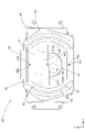
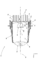
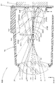
- FIG. 1 is a side sectional view showing a vehicle lamp 100 provided with a lamp unit 10 according to an embodiment of the present invention. Further, FIG. 2 is a view taken along the line II in FIG. 1.
- the direction indicated by X is the "front of the unit”
- the direction indicated by Y is the “left direction” orthogonal to the "front of the unit” ("right direction” when viewed from the front of the unit)
- the direction indicated by Z Is "upward”. The same applies to figures other than these.
- the vehicle lamp 100 is a headlamp provided at the front end of the vehicle, and the lamp unit 10 is in the front-rear direction (that is, the unit front-rear direction) in the lamp chamber formed by the lamp body 102 and the translucent cover 104. It is configured to be housed in a state where the optical axis is adjusted so as to substantially match the front-rear direction of the vehicle.
- the lamp unit 10 is a projector-type lamp unit, and by irradiating the light from the light source 20 toward the front of the unit via the projection lens 30, a low beam light distribution pattern and a high beam light distribution pattern (this). Will be described later).
- the projection lens 30 has an optical axis Ax extending in the front-rear direction of the unit, and the light distribution pattern is formed by reverse-projecting a projection image formed on the rear focal plane.
- a light guide body 40 configured to guide the light emitted from the light source 20 and make it enter the projection lens 30 is arranged. There is. Then, the light guide body 40 forms the projection image.
- FIG. 3 is a side sectional view showing the lamp unit 10 as a single item.
- 4 is a sectional view taken along line IV-IV of FIG. 3
- FIG. 5 is a sectional view taken along line VV of FIG. 3
- FIG. 6 is a sectional view taken along line VI-VI of FIG.
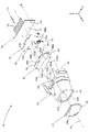
- FIG. 7 is an exploded perspective view showing the lamp unit 10 when viewed from diagonally forward
- FIG. 8 is an exploded perspective view showing the lamp unit 10 when viewed from diagonally rearward.
- the projection lens 30 is a biconvex aspherical lens having an outer peripheral flange portion 32, and is made of a colorless and transparent acrylic resin member.
- the projection lens 30 is supported by the lens holder 50 at its outer peripheral flange portion 32.
- the lens holder 50 is a tubular member extending in the front-rear direction of the unit, and is made of an opaque polycarbonate resin member, and an annular lens support portion 52 is formed at the front end portion thereof.
- the projection lens 30 is fixed to the lens holder 50 by laser welding in a state where the outer peripheral flange portion 32 is pressed against the lens support portion 52 of the lens holder 50 from the front side of the unit.
- a pair of upper and lower positioning pins 52a and 52b formed on the lens support portion 52 of the lens holder 50 have positioning holes 32a and positioning grooves 32b formed on the upper and lower portions of the outer peripheral flange portion 32 of the projection lens 30.
- the light source 20 is composed of four light emitting elements 22A, 22B, 22C, and 22D mounted on a common substrate 24.
- the four light emitting elements 22A to 22D are all white light emitting diodes having a horizontally long rectangular light emitting surface, and are arranged in a state where the light emitting surface faces the front of the unit.
- three light emitting elements 22A to 22D are lit when forming a low beam light distribution pattern, and the remaining one light emitting element 22D forms a high beam light distribution pattern. It is designed to light up additionally when you do.
- the three light emitting elements 22A to 22C are arranged at a position directly above the optical axis Ax of the projection lens 30 and at positions separated by a certain amount on both the left and right sides thereof, and the light emitting element 22D is arranged at a position directly below the optical axis Ax. Has been done.
- the substrate 24 is supported by the lens holder 50 in a state of being arranged so as to extend along a vertical plane orthogonal to the optical axis Ax of the projection lens 30 (this will be described later).
- a connector 26 electrically connected to four light emitting elements 22A to 22D via a conductive pattern (not shown) is mounted.
- a power supply side connector (not shown) to the connector 26
- electric power is supplied to the four light emitting elements 22A to 22D.
- the light guide body 40 is made of a colorless and transparent polycarbonate resin member.
- the light guide body 40 has a first emission surface 42A for emitting light for a low beam light distribution pattern, and additional light distribution added to the low beam light distribution pattern when forming a high beam light distribution pattern. It is provided with a second emission surface 42B for emitting light for a pattern.
- the first exit surface 42A is located at the upper part of the front surface of the light guide body 40, and is formed so as to extend along the rear focal surface of the projection lens 30. As shown in FIG. 7, the first exit surface 42A has a substantially horizontally long rectangular outer shape in which the left and right upper corners are chamfered. Then, as shown in FIGS. Has been done.
- the second emission surface 42B is located at the lower part of the front surface of the light guide body 40, and is located at a position separated by a certain amount from the rear focal plane of the projection lens 30 to the rear side of the unit, and is aligned with the optical axis Ax of the projection lens 30. It is formed so as to extend along a plane slightly tilted backward with respect to the orthogonal vertical planes.
- the second exit surface 42B is located directly below the optical axis Ax, and has a substantially oblong elliptical outer shape with an upper portion missing.
- the light guide body 40 includes a block portion 42 extending toward the rear of the unit while substantially maintaining the outer shape of the first exit surface 42A.
- the lower surface of the block portion 42 is formed as a connecting surface 42C extending horizontally from the lower end edge 42Aa of the first exit surface 42A to the upper end edge 42Ba of the second exit surface 42B toward the rear of the unit.
- a mirror surface portion 42C1 is provided on the connection surface 42C (this will be described later).
- the light guide body 40 includes four incident portions 44A, 44B, 44C, 44D for incident light emitted from each of the four light emitting elements 22A, 22B, 22C, 22D.
- the three incident portions 44A to 44C are formed so as to be located on the front side of the unit with respect to each of the three light emitting elements 22A to 22C and on the rear side of the unit with respect to the block portion 42.
- the remaining one incident portion 44D is formed so as to be located on the front side of the unit with respect to the light emitting element 22D and on the rear side of the unit with respect to the second emission surface 42B.
- the three incident portions 44A to 44C are configured so that the emitted light from each of the three light emitting elements 22A to 22C is incident and then directly or totally reflected before being guided into the block portion 42.
- the block portion 42 is configured to guide the incident light from the three incident portions 44A to 44C to the first exit surface 42A, and at that time, the light that reaches the connection surface 42C is totally reflected by the connection surface 42C. After that, it is configured to lead to the first exit surface 42A.
- the incident portion 44D is configured to incident the emitted light from the light emitting element 22D, directly or totally reflect it, and then guide the emitted light to the second emitting surface 42B.
- the light from the light emitting element 22B incident on the light guide body 40 from the incident portion 44B located directly above the optical axis Ax is emitted from the first emission surface 42A toward the projection lens 30.
- the light is emitted from the projection lens 30 toward the front of the unit as light that is substantially downward.
- the light from the light emitting element 22D incident on the light guide body 40 from the incident portion 44D is emitted from the second emission surface 42B toward the projection lens 30, and is directed toward the front of the unit as light substantially upward from the projection lens 30. Be irradiated.
- outer peripheral flange portions 46 extending along a vertical surface orthogonal to the optical axis Ax are formed on the upper portion and the left and right side portions at the rear end portion of the block portion 42. ing.
- the light guide body 40 is supported by the lens holder 50 at the outer peripheral flange portion 46 in a state of being accommodated in the internal space of the lens holder 50.
- the lens holder 50 is formed with a light guide body support portion 54 extending along the outer peripheral flange portion 46 of the light guide body 40.
- the light guide body 40 is fixed to the lens holder 50 by laser welding in a state where the outer peripheral flange portion 46 is pressed against the rear surface of the light guide body support portion 54 of the lens holder 50 from the rear side of the unit. There is.
- the pair of left and right positioning holes 46a formed in the outer peripheral flange portion 46 of the light guide body 40 engage with the pair of left and right positioning pins 54a formed in the light guide body support portion 54 of the lens holder 50.
- the light guide body 40 is positioned with respect to the lens holder 50 in a direction orthogonal to the front-rear direction of the unit.
- the lamp unit 10 includes a metal (for example, aluminum) heat sink 70 for dissipating heat generated by the four light emitting elements 22A, 22B, 22C, and 22D.
- a metal for example, aluminum
- the heat sink 70 includes a main body portion 72 extending along a vertical plane orthogonal to the optical axis Ax of the projection lens 30, and a plurality of heat radiation fins 74 extending along the vertical plane from the main body portion 72 toward the rear of the unit. ing.
- the heat sink 70 is supported by the lens holder 50 together with the substrate 24 in a state where the heat sink 70 is in surface contact with the rear surface of the substrate 24 on the front surface of the main body 72.
- the substrate 24 and the heat sink 70 are supported by the lens holder 50 by mechanical fastening. Specifically, the substrate 24 and the heat sink 70 are fixed to the lens holder 50 by being screwed to the lens holder 50 at two locations on the left and right sides thereof.
- a pair of left and right screw tightening bosses 56 are formed in the lens holder 50, and a pair of left and right screw insertion holes for inserting the co-tightening screws 76 into the main body 72 of the substrate 24 and the heat sink 70. 24a and 72a are formed, respectively.
- the lens holder 50 is formed with stepped positioning pins 58 extending toward the rear of the unit at three locations, the central upper end portion and the left and right lower end portions. Further, the substrate 24 is formed with positioning holes 24b at three locations, a central upper end portion and a left and right lower end portions. Then, the small diameter portion 58a at the tip of each stepped positioning pin 58 is inserted into each positioning hole 24b of the substrate 24, and the substrate 24 comes into contact with the tip flat portion 58b of each stepped positioning pin 58 with respect to the lens holder 50. The substrate 24 is positioned in the front-rear direction of the unit and in the direction orthogonal to the unit.
- a reinforcing rib 60 formed in a substantially U shape so as to be connected to the base end portion of the stepped positioning pin 58 is formed on the upper wall portion of the lens holder 50.
- the lens holder 50 is formed with a pair of left and right positioning portions 62 for positioning the heat sink 70 in a direction orthogonal to the front-rear direction of the unit. These positioning portions 62 are formed so as to extend toward the rear of the unit in a shape that wraps around the upper and lower end faces of the main body 72 at positions close to the left and right end faces of the main body 72 of the heat sink 70.
- L-shaped notches 62a are formed at the upper and lower ends of the pair of left and right positioning portions 62.
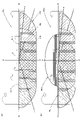
- FIG. 9 is a detailed view of the main part of FIG. Further, FIG. 10 is a detailed view of the X portion of FIG. Further, FIG. 11A is a sectional view taken along line XIa-XIa of FIG.
- the connecting surface 42C constituting the lower surface of the block portion 42 in the light guide body 40 is provided with a mirror surface portion 42C1 over the entire region thereof.
- the mirror surface portion 42C1 is formed by vacuum-depositing aluminum on the surface of the connection surface 42C.
- the first emission surface 42A directly.
- the light is emitted from the first emission surface 42A toward the projection lens 30 as diagonally downward light, but some of the light is totally reflected by the connection surface 42C and then reaches the first emission surface 42A, and the first emission surface 42A is reached. Is emitted toward the projection lens 30 as light obliquely upward.
- the light from the light emitting element 22D incident on the light guide body 40 from the incident portion 44D is emitted from the second emission surface 42B toward the projection lens 30, and then most of the light reaches the projection lens 30 as it is. Some light reaches the connection surface 42C.
- the mirror surface portion 42C1 is not provided on the connection surface 42C, the light that reaches the connection surface 42C is transmitted from the connection surface 42C to the block portion 42 as shown by the two-dot chain line in the figure.
- the light is emitted from the first emission surface 42A in a direction deviating from the projection lens 30 as obliquely upward light.
- the mirror surface portion 42C1 is provided over the entire area of the connection surface 42C, the light that reaches the connection surface 42C is reflected by the mirror surface portion 42C1 and reaches the projection lens 30 as diagonally downward light. do.
- FIG. 12 is a perspective view showing a light distribution pattern formed on a virtual vertical screen arranged at a position 25 m in front of the vehicle by the light emitted from the lamp unit 10 of the vehicle lamp 100 toward the front of the unit.
- 12A is a diagram showing a low beam light distribution pattern PL
- FIG. 12B is a diagram showing a high beam light distribution pattern PH1.
- the low beam light distribution pattern PL is a left light distribution low beam light distribution pattern, and has cut-off lines CL1 and CL2 on the upper end edge thereof.
- the cut-off lines CL1 and CL2 extend horizontally with a VV line that passes vertically through the HV, which is the vanishing point in the front direction of the lamp, in a horizontal step, and are on the right side of the VV line.
- the oncoming lane side portion is formed as a lower cut-off line CL1
- the own lane side portion on the left side of the VV line is formed as an upper cut-off line CL2 which is stepped up from this lower cut-off line CL1 via an inclined portion. It is formed.
- the elbow point E which is the intersection of the lower cut-off line CL1 and the VV line, is located about 0.5 to 0.6 ° below the HV.
- the low beam light distribution pattern PL is formed as a composite light distribution pattern of three light distribution patterns PA, PB, and PC.
- Each light distribution pattern PA, PB, PC is formed as an inverted projection image of a projection image formed on the first emission surface 42A of the light guide body 40 by the emission light from each light emitting element 22A, 22B, 22C. It is a light pattern.
- the low beam light distribution pattern PL formed as these combined light distribution patterns has an outer shape substantially corresponding to the outer shape of the first emission surface 42A of the light guide body 40.
- the low beam light distribution pattern PL includes the cut-off lines CL1 and CL2. It is clearly formed.
- the high beam light distribution pattern PH1 has an additional light distribution pattern PD1 extending above the cut-off line CL1 and CL2 added to the low beam light distribution pattern PL. ing.
- This additional light distribution pattern PD1 is formed as an inverted projection image of a projection image formed on the rear focal plane of the projection lens 30 by the light emitted from the light emitting element 22D emitted from the second emission surface 42B of the light guide body 40. It is a light distribution pattern to be performed.
- the upper end position of the projection image is defined by the lower end edge 42Aa of the first emission surface 42A
- the lower end position of the additional light distribution pattern PD1 is defined by the cut-off line CL1 and CL2. Become. Therefore, the high beam light distribution pattern PH1 is such that the low beam light distribution pattern PL and the additional light distribution pattern PD1 are connected without a gap.
- the lighting equipment unit 10 is configured to irradiate the light from the light source 20 toward the front of the unit via the projection lens 30, but there is a light source between the light source 20 and the projection lens 30. Since the light guide body 40 configured to guide the light emitted from the 20 and incident on the projection lens 30, the light source 40 controls the incident light to the projection lens 30. A light distribution pattern having a desired shape can be formed.
- the light source 20 is arranged for a high beam by simultaneously lighting three light emitting elements 22A, 22B, 22C (first light source) for forming a low beam light distribution pattern PL and these light emitting elements 22A to 22C.
- a light emitting element 22D (second light source) for forming the light pattern PH1 is provided, and the light guide body 40 has a first light emitting surface 42A for emitting light for the low beam light distribution pattern PL.
- the low beam is provided with a second emission surface 42B for emitting light for the additional light distribution pattern PD1 added to the low beam light distribution pattern PL when the high beam light distribution pattern PH1 is formed.
- the light distribution pattern PL for light distribution and the light distribution pattern PH1 for high beam can be selectively formed.
- the cut-off line CL1 and CL2 of the low beam light distribution pattern PL can be formed by the shape of 42Aa.
- the light guide body 40 includes a connection surface 42C extending toward the rear of the unit from the lower end edge 42Aa of the first emission surface 42A to the upper end edge 42Ba of the second emission surface 42B, and the connection surface 42C is provided with the connection surface 42C. Since the mirror surface portion 42C1 is provided, the following effects can be obtained.
- the light flux is used for the emitted light from the light emitting element 22D. Since the rate is lowered and the brightness of the additional light distribution pattern PD1 is lowered, the high beam light distribution pattern PH1 cannot be formed with the desired luminous intensity distribution.
- the mirror surface portion 42C1 is provided in the entire region of the connection surface 42C of the light guide body 40, the light from the light emitting element 22D emitted from the second emission surface 42B and reached the connection surface 42C. Can be prevented from re-entering the light guide body 40 from the connection surface 42C. Then, the light from the light emitting element 22D that has reached the connection surface 42C can be reflected by the mirror surface portion 42C1 and used as light for forming the additional light distribution pattern PD1, whereby the light distribution for the high beam can be used.
- the pattern PH1 can be formed with the desired light intensity distribution.
- the light guide body 40 is composed of a single member, the above-mentioned effects can be obtained while reducing the cost by reducing the number of parts of the lamp unit 10.
- each of the low beam light distribution pattern PL and the high beam light distribution pattern PH1. can be formed appropriately.
- the lamp unit 10 includes three light emitting elements 22A, 22B, 22C as a first light source for forming a low beam light distribution pattern PL, and three light emitting elements as a light guide body 40. Since the three incident portions 44A to 44C for incident the emitted light from each of the elements 22A, 22B, and 22C are provided, the low beam light distribution pattern PL can be clearly formed in a desired shape.
- the light guide body 40 has been described as being composed of a colorless and transparent polycarbonate resin member, but is composed of a colorless and transparent acrylic resin member, a colorless and transparent glass member, and the like. It is also possible to.
- the mirror surface portion 42C1 is provided over the entire region of the connection surface 42C, but the light guide body 40 includes a region in which the mirror surface portion 42C1 is not partially provided. It is also possible to have a different configuration.
- the four light emitting elements 22A to 22D have been described as having a horizontally long rectangular light emitting surface, but have other external shapes (for example, a square shape, a vertically long rectangular shape, etc.). It is also possible to configure it.
- the first light source is composed of three light emitting elements 22A, 22B, and 22C
- the second light source is composed of one light emitting element 22D.
- the first and second light sources have been described. It is also possible to set the number of each of the light sources to a number different from that of the above embodiment.
- FIG. 11 (b) is a diagram similar to FIG. 11 (a) showing a main part of the lamp unit according to this modified example.
- the basic configuration of this modification is the same as that of the above embodiment, but a part of the configuration of the light guide body 140 is different from that of the above embodiment.
- the light guide body 140 of this modification also has a configuration in which the mirror surface portion 142C1 is provided on the connection surface 142C constituting the lower surface of the block portion 142, but a part of the connection surface 142C is a light transmitting portion. It differs from the case of the above embodiment in that it is configured as 142C2.
- the region located in the vicinity of the rear focal point F of the projection lens 30 (see FIG. 1) on the connection surface 142C is not provided with the mirror surface portion 142C1 (that is, vacuum deposition of aluminum or the like is not performed). ) It is configured as a light transmitting portion 142C2 having a transparent surface shape.
- the light transmitting portion 142C2 is set as a semi-circular region having a radius R centered on the rear focal point F of the projection lens 30 in a plan view.
- the value of the radius R is 1/3 or less (for example, the width from the lower end edge 142Aa of the first exit surface 142A to the upper end edge 142Ba of the second exit surface 142B) D of the connection surface 142C. It is set to a value of about 1/10 to 1/4).
- the portion near the focal point located near the rear focal point F of the projection lens 30 is focused by sunlight or the like incident from the outside of the lamp unit via the projection lens 30. It may become hot.
- the light guide body 140 of this modification is made of a resin member, it is easily melted by the light collecting action of sunlight or the like. If 142C is provided, heat is likely to be trapped in a portion near the focal point of the light guide body 140, so that melting damage is more likely to occur.
- the block portion of the light guide body 140 A part of the sunlight or the like incident on the portion near the focal point in 142 can be emitted to the lower space without being reflected by the connecting surface 142C.
- the light transmitting portion 142C2 has been described as being set as a semi-circular region, but it is also possible to configure the region as a region having a shape other than this.
- FIG. 13 is a diagram similar to FIG. 9 showing the lamp unit 210 according to this modification
- FIG. 14 is a detailed view of the XIV portion of FIG.
- FIG. 11 (c) is a sectional view taken along line XIc-XIc of FIG. 14 (that is, a diagram similar to that of FIG. 11 (a)).
- the basic configuration of this modification is the same as that of the above embodiment, but a part of the configuration of the light guide body 240 is different from that of the above embodiment.
- the light guide body 240 of this modification also has a configuration in which a mirror surface portion 242C1 having a transparent surface is provided on the connection surface 242C constituting the lower surface of the block portion 242, but near the front end edge of the connection surface 242C.
- the region is different from the case of the above embodiment in that the region is configured as the light transmitting portion 242C2.
- connection surface 242C is not provided with a mirror surface portion 242C1 in a band-shaped region having a certain front-rear width from the lower end edge 242Aa of the first exit surface 242A (that is,). It is configured as a light-transmitting portion 242C2 having a transparent surface (without vacuum deposition of aluminum).
- FIG. 15 is a diagram similar to FIG. 12 showing a light distribution pattern formed by irradiation light from the lamp unit 210 according to the present modification.
- the low beam light distribution pattern PL shown in FIG. 15A is the same as that of the above embodiment, but the high beam light distribution pattern PH2 shown in FIG. 15B is different from that of the above embodiment.
- the high beam light distribution pattern PH2 has an additional light distribution pattern PD2 added to the low beam light distribution pattern PL, and the additional light distribution pattern PD2 has a low beam at its lower end edge PD2a. It is formed in a state where it partially overlaps with the vicinity region of the cut-off line CL1 and CL2 in the light distribution pattern PL.
- the lower end edge portion PD2a is formed as the additional light distribution pattern PD2 in a state of partially overlapping the vicinity regions of the cut-off line CL1 and CL2 in the low beam light distribution pattern PL. Therefore, the high beam light distribution pattern PH2 can be formed as a substantially uniform light distribution pattern in which the low beam light distribution pattern PL and the additional light distribution pattern PD2 are smoothly connected.
- the front-rear width D2 of the light transmitting portion 242C2 is set to a value of 1/3 or less with respect to the front-rear width D of the connection surface 42C, so that the light distribution pattern for high beam is set.
- PH2 can be formed with a more preferable light intensity distribution.
- connection surface 242C of the light guide body 240 has a region located in the vicinity of the rear focal point F of the projection lens 30 as a light transmitting portion 242C2, so that the block portion of the light guide body 240 is formed.
- a part of sunlight or the like incident on the portion near the focal point in 242 can be emitted to the lower space without being reflected by the connecting surface 242C.
- heat can be prevented from being trapped in the vicinity of the focal point, so that the occurrence of melting damage can be effectively suppressed.
- the light transmitting portion 242C2 of the connecting surface 242C has been described as being configured as a band-shaped region having a constant front-rear width D1 from the lower end edge 242Aa of the first exit surface 242A.
- a band-shaped region whose front-rear width changes depending on the position of the light transmitting portion 242C2 in the left-right direction, or a position slightly distant from the lower end edge 242Aa of the first exit surface 242A to the rear side of the unit is used as the front end edge. It is possible to adopt a band-shaped region having a certain front-back width.
- FIG. 11 (d) is a diagram similar to FIG. 11 (a) showing a main part of the lamp unit according to this modified example.
- the basic configuration of this modification is the same as that of the second modification, but a part of the configuration of the light transmitting portion 342C2 is the same as that of the second modification. It's different.
- the region near the front end edge of the connecting surface 342C constituting the lower surface of the block portion 342 is configured as the light transmitting portion 342C2, but the light transmitting portion 342C2 is a transparent surface. It is different from the case of the second modification in that it is composed of a semi-transmissive surface.
- the light transmitting portion 342C2 of the present modification is set as a band-shaped region having the same shape as the light transmitting portion 242C2 of the second modification, but the strip-shaped region is configured by half-deposited aluminum. .. As a result, the light transmitting portion 342C2 is configured not to transmit all the light that has reached the connection surface 342C but to reflect some percentage of the light.
- the reflectance of the mirror surface portion 342C1 is set to a value of 90% or more, whereas the reflectance of the light transmitting portion 342C2 is set to a value of 50% or less (for example, about 30 to 40%). Value) is set.
- the additional light distribution pattern formed by the irradiation light from the lamp unit according to the present modification is in the lower vicinity of the cut-off line CL1 and CL2 at the lower end edge portion PD2a of the additional light distribution pattern PD2 shown in FIG.
- the brightness of the region is slightly reduced, but the brightness of the region in the upper vicinity of the cut-off line CL1 and CL2 is increased by that amount. Therefore, as the high beam light distribution pattern, after maintaining the state of being formed as a substantially uniform light distribution pattern in which the low beam light distribution pattern PL and the additional light distribution pattern are smoothly connected, the high beam light distribution pattern PH2 Can also be excellent in distant visibility.
- Lamp unit 20 Light source 22A, 22B, 22C Light emitting element (first light source) 22D light emitting element (second light source) 24 Substrate 24a, 72a Screw insertion hole 24b, 32a, 46a Positioning hole 26 Connector 30 Projection lens 32 Outer peripheral flange part 32b Positioning groove 40, 140, 240, 340 Light guide body 42, 142, 242, 342 Block part 42A, 142A, 242A First exit surface 42Aa, 142Aa, 242Aa Lower edge 42B, 142B Second emission surface 42Ba, 142Ba Upper edge 42C, 142C, 242C, 342C Connection surface 42C1, 142C1, 242C1, 342C1 Mirror surface 44A, 44B, 44C, 44D Part 46 Outer peripheral flange part 50 Lens holder 52 Lens support part 52a, 52b, 54a Positioning pin 54 Light guide body support part 56 Screw tightening boss 58 Stepped positioning pin 58a Tip small diameter part 58b Tip flat
Landscapes
- Engineering & Computer Science (AREA)
- General Engineering & Computer Science (AREA)
- Physics & Mathematics (AREA)
- Microelectronics & Electronic Packaging (AREA)
- Optics & Photonics (AREA)
- Non-Portable Lighting Devices Or Systems Thereof (AREA)
Abstract
Description
光源からの光を、投影レンズを介してユニット前方へ向けて照射するように構成された灯具ユニットにおいて、
上記光源と上記投影レンズとの間に、上記光源からの出射光を導光して上記投影レンズに入射させるように構成された導光体が配置されており、
上記光源として、ロービーム用配光パターンを形成するための第1光源と、上記第1光源との同時点灯によってハイビーム用配光パターンを形成するための第2光源とを備えており、
上記導光体は、上記ロービーム用配光パターン用の光を出射するための第1出射面と、上記ハイビーム用配光パターンを形成する際に上記ロービーム用配光パターンに対して付加される付加配光パターン用の光を出射するための第2出射面とを備えており、
上記第2出射面は、上記第1出射面の下方側において上記第1出射面に対してユニット後方側に変位した位置に形成されており、
上記導光体は、上記第1出射面の下端縁から上記第2出射面の上端縁までユニット後方へ向けて延びる接続面を備えており、
上記接続面に鏡面部が設けられている、ことを特徴とするものである。
20 光源
22A、22B、22C 発光素子(第1光源)
22D 発光素子(第2光源)
24 基板
24a、72a ネジ挿通孔
24b、32a、46a 位置決め孔
26 コネクタ
30 投影レンズ
32 外周フランジ部
32b 位置決め溝
40、140、240、340 導光体
42、142、242、342 ブロック部
42A、142A、242A 第1出射面
42Aa、142Aa、242Aa 下端縁
42B、142B 第2出射面
42Ba、142Ba 上端縁
42C、142C、242C、342C 接続面
42C1、142C1、242C1、342C1 鏡面部
44A、44B、44C、44D 入射部
46 外周フランジ部
50 レンズホルダ
52 レンズ支持部
52a、52b、54a 位置決めピン
54 導光体支持部
56 ネジ締め用ボス
58 段付き位置決めピン
58a 先端小径部
58b 先端平面部
60 補強リブ
62 位置決め部
62a 切欠き部
70 ヒートシンク
72 本体部
74 放熱フィン
76 ネジ
100 車両用灯具
102 ランプボディ
104 透光カバー
142C2、242C2、342C2 光透過部
Ax 光軸
CL1 下段カットオフライン
CL2 上段カットオフライン
D 接続面の前後幅
D1 光透過部の前後幅
E エルボ点
F 後側焦点
PA、PB、PC 配光パターン
PD1、PD2 付加配光パターン
PD2a 下端縁部
PH1、PH2 ハイビーム用配光パターン
PL ロービーム用配光パターン
R 光透過部の半径
Claims (6)
- 光源からの光を、投影レンズを介してユニット前方へ向けて照射するように構成された灯具ユニットにおいて、
上記光源と上記投影レンズとの間に、上記光源からの出射光を導光して上記投影レンズに入射させるように構成された導光体が配置されており、
上記光源として、ロービーム用配光パターンを形成するための第1光源と、上記第1光源との同時点灯によってハイビーム用配光パターンを形成するための第2光源とを備えており、
上記導光体は、上記ロービーム用配光パターン用の光を出射するための第1出射面と、上記ハイビーム用配光パターンを形成する際に上記ロービーム用配光パターンに対して付加される付加配光パターン用の光を出射するための第2出射面とを備えており、
上記第2出射面は、上記第1出射面の下方側において上記第1出射面に対してユニット後方側に変位した位置に形成されており、
上記導光体は、上記第1出射面の下端縁から上記第2出射面の上端縁までユニット後方へ向けて延びる接続面を備えており、
上記接続面に鏡面部が設けられている、ことを特徴とする灯具ユニット。 - 上記接続面は、上記投影レンズの後側焦点の近傍に位置する領域が光透過部として構成されている、ことを特徴とする請求項1記載の灯具ユニット。
- 上記接続面は、上記接続面の前端縁近傍領域が光透過部として構成されている、ことを特徴とする請求項1または2記載の灯具ユニット。
- 上記前端縁近傍領域の前後幅は、上記接続面の前後幅に対して1/3以下の値に設定されている、ことを特徴とする請求項3記載の灯具ユニット。
- 上記導光体は樹脂製部材で構成されている、ことを特徴とする請求項2~4いずれか記載の灯具ユニット。
- 上記第1光源を複数個備えており、
上記導光体は、上記複数の第1光源の各々からの出射光を入射させるための複数の入射部を備えている、ことを特徴とする請求項1~5いずれか記載の灯具ユニット。
Priority Applications (3)
| Application Number | Priority Date | Filing Date | Title |
|---|---|---|---|
| EP21906360.9A EP4265959A4 (en) | 2020-12-15 | 2021-12-02 | LAMP UNIT |
| CN202180082464.XA CN116601427A (zh) | 2020-12-15 | 2021-12-02 | 灯具单元 |
| US18/256,255 US12013093B2 (en) | 2020-12-15 | 2021-12-02 | Lamp unit |
Applications Claiming Priority (2)
| Application Number | Priority Date | Filing Date | Title |
|---|---|---|---|
| JP2020-207632 | 2020-12-15 | ||
| JP2020207632A JP7530281B2 (ja) | 2020-12-15 | 2020-12-15 | 灯具ユニット |
Publications (1)
| Publication Number | Publication Date |
|---|---|
| WO2022130997A1 true WO2022130997A1 (ja) | 2022-06-23 |
Family
ID=82057529
Family Applications (1)
| Application Number | Title | Priority Date | Filing Date |
|---|---|---|---|
| PCT/JP2021/044226 Ceased WO2022130997A1 (ja) | 2020-12-15 | 2021-12-02 | 灯具ユニット |
Country Status (5)
| Country | Link |
|---|---|
| US (1) | US12013093B2 (ja) |
| EP (1) | EP4265959A4 (ja) |
| JP (1) | JP7530281B2 (ja) |
| CN (1) | CN116601427A (ja) |
| WO (1) | WO2022130997A1 (ja) |
Families Citing this family (5)
| Publication number | Priority date | Publication date | Assignee | Title |
|---|---|---|---|---|
| JP7749496B2 (ja) * | 2022-03-14 | 2025-10-06 | スタンレー電気株式会社 | 車両用灯具 |
| JP2024101856A (ja) * | 2023-01-18 | 2024-07-30 | スタンレー電気株式会社 | 車両用灯具 |
| KR20250026630A (ko) * | 2023-08-17 | 2025-02-25 | 현대모비스 주식회사 | 차량용 램프 |
| JP2025182912A (ja) * | 2024-06-04 | 2025-12-16 | スタンレー電気株式会社 | 車両用灯具 |
| WO2026048571A1 (ja) * | 2024-08-30 | 2026-03-05 | 株式会社小糸製作所 | 灯具ユニット |
Citations (2)
| Publication number | Priority date | Publication date | Assignee | Title |
|---|---|---|---|---|
| JP2017199660A (ja) | 2016-04-11 | 2017-11-02 | ヴァレオ ビジョンValeo Vision | 光ビームを放出するための自動車両ヘッドライト・モジュール |
| JP2019160805A (ja) * | 2014-07-08 | 2019-09-19 | 三菱電機株式会社 | 前照灯モジュール |
Family Cites Families (12)
| Publication number | Priority date | Publication date | Assignee | Title |
|---|---|---|---|---|
| DE102009008631B4 (de) | 2009-02-12 | 2016-11-03 | Automotive Lighting Reutlingen Gmbh | Projektionsmodul für einen Kraftfahrzeugscheinwerfer |
| DE102010023360A1 (de) | 2009-10-05 | 2011-04-07 | Automotive Lighting Reutlingen Gmbh | Zur Erzeugung verschiedener Lichtverteilungen eingerichteter Kraftfahrzeugscheinwerfer mit Halbleiterlichtquellen |
| FR2995967B1 (fr) * | 2012-09-24 | 2019-09-06 | Valeo Vision | Module d'eclairage, notamment pour vehicule automobile |
| JP6214446B2 (ja) * | 2014-03-26 | 2017-10-18 | 三菱電機株式会社 | 車載用前照灯 |
| JP6448250B2 (ja) | 2014-08-11 | 2019-01-09 | 株式会社小糸製作所 | 車両用灯具 |
| WO2016162921A1 (ja) * | 2015-04-06 | 2016-10-13 | 三菱電機株式会社 | 前照灯用光源および前照灯 |
| CN104832859B (zh) * | 2015-05-29 | 2018-08-07 | 奇瑞汽车股份有限公司 | 一种远近光一体的前照灯 |
| DE102016008422A1 (de) * | 2016-07-11 | 2018-01-11 | GM Global Technology Operations LLC (n. d. Ges. d. Staates Delaware) | Leuchte für ein Kraftfahrzeug |
| DE202017106281U1 (de) * | 2017-10-17 | 2019-01-18 | Automotive Lighting Reutlingen Gmbh | Lichtleiter-Anordnung und Kraftfahrzeug-Beleuchtungseinrichtung mit einer solchen Lichtleiter-Anordnung |
| KR102463275B1 (ko) * | 2017-12-28 | 2022-11-04 | 에스엘 주식회사 | 차량용 램프 |
| DE102018110793B4 (de) | 2018-05-04 | 2026-02-05 | HELLA GmbH & Co. KGaA | Projektionsscheinwerfer |
| CN212132312U (zh) | 2020-03-09 | 2020-12-11 | 华域视觉科技(上海)有限公司 | 初级光学元件组件、车辆照明装置、车灯和车辆 |
-
2020
- 2020-12-15 JP JP2020207632A patent/JP7530281B2/ja active Active
-
2021
- 2021-12-02 CN CN202180082464.XA patent/CN116601427A/zh active Pending
- 2021-12-02 US US18/256,255 patent/US12013093B2/en active Active
- 2021-12-02 EP EP21906360.9A patent/EP4265959A4/en not_active Withdrawn
- 2021-12-02 WO PCT/JP2021/044226 patent/WO2022130997A1/ja not_active Ceased
Patent Citations (2)
| Publication number | Priority date | Publication date | Assignee | Title |
|---|---|---|---|---|
| JP2019160805A (ja) * | 2014-07-08 | 2019-09-19 | 三菱電機株式会社 | 前照灯モジュール |
| JP2017199660A (ja) | 2016-04-11 | 2017-11-02 | ヴァレオ ビジョンValeo Vision | 光ビームを放出するための自動車両ヘッドライト・モジュール |
Non-Patent Citations (1)
| Title |
|---|
| See also references of EP4265959A4 |
Also Published As
| Publication number | Publication date |
|---|---|
| EP4265959A1 (en) | 2023-10-25 |
| US12013093B2 (en) | 2024-06-18 |
| JP7530281B2 (ja) | 2024-08-07 |
| CN116601427A (zh) | 2023-08-15 |
| EP4265959A4 (en) | 2024-05-15 |
| US20240019094A1 (en) | 2024-01-18 |
| JP2022094635A (ja) | 2022-06-27 |
Similar Documents
| Publication | Publication Date | Title |
|---|---|---|
| WO2022130997A1 (ja) | 灯具ユニット | |
| JP4970136B2 (ja) | 車両用前照灯の灯具ユニット | |
| CN108351080B (zh) | 车辆用灯具 | |
| JP4684952B2 (ja) | 車両用前照灯の灯具ユニット | |
| KR100645863B1 (ko) | 차량용 전조등 | |
| JP4360191B2 (ja) | 車両用前照灯 | |
| JP4044024B2 (ja) | 車両用前照灯 | |
| US7131758B2 (en) | Vehicle headlamp with light-emitting unit shifted from optical axis of lens | |
| KR100934425B1 (ko) | 차량용 전조등의 등기구 유닛 | |
| KR100934682B1 (ko) | 차량용 전조등의 등기구 유닛 | |
| US20050162857A1 (en) | Lamp unit for vehicle and illumination lamp for vehicle | |
| JP2017204400A (ja) | 車両用灯具 | |
| JP5206364B2 (ja) | 車両用灯具 | |
| KR102109910B1 (ko) | 차량용 전조등 | |
| CN108224352B (zh) | 灯具 | |
| JP5935507B2 (ja) | 車両用前照灯 | |
| KR20220045827A (ko) | 차량용 발광 모듈 및 이를 포함하는 램프 장치 | |
| JP2008258001A (ja) | 車両用前照灯の灯具ユニット | |
| JP6322931B2 (ja) | 車両用灯具 | |
| JP4809635B2 (ja) | 車両用前照灯 | |
| JP5982986B2 (ja) | 車両用前照灯 | |
| JP7028618B2 (ja) | 車両用灯具 | |
| JP7628050B2 (ja) | 車両用灯具 | |
| JP7449939B2 (ja) | 車両用灯具 | |
| WO2014207817A1 (ja) | 車両用前照灯 |
Legal Events
| Date | Code | Title | Description |
|---|---|---|---|
| 121 | Ep: the epo has been informed by wipo that ep was designated in this application |
Ref document number: 21906360 Country of ref document: EP Kind code of ref document: A1 |
|
| WWE | Wipo information: entry into national phase |
Ref document number: 202180082464.X Country of ref document: CN Ref document number: 18256255 Country of ref document: US |
|
| NENP | Non-entry into the national phase |
Ref country code: DE |
|
| ENP | Entry into the national phase |
Ref document number: 2021906360 Country of ref document: EP Effective date: 20230717 |