WO2022138109A1 - 圧力測定装置および医療装置 - Google Patents
圧力測定装置および医療装置 Download PDFInfo
- Publication number
- WO2022138109A1 WO2022138109A1 PCT/JP2021/044720 JP2021044720W WO2022138109A1 WO 2022138109 A1 WO2022138109 A1 WO 2022138109A1 JP 2021044720 W JP2021044720 W JP 2021044720W WO 2022138109 A1 WO2022138109 A1 WO 2022138109A1
- Authority
- WO
- WIPO (PCT)
- Prior art keywords
- flow path
- blood
- pressure
- joint
- circuit
- Prior art date
- Legal status (The legal status is an assumption and is not a legal conclusion. Google has not performed a legal analysis and makes no representation as to the accuracy of the status listed.)
- Ceased
Links
Images





Classifications
-
- A—HUMAN NECESSITIES
- A61—MEDICAL OR VETERINARY SCIENCE; HYGIENE
- A61M—DEVICES FOR INTRODUCING MEDIA INTO, OR ONTO, THE BODY; DEVICES FOR TRANSDUCING BODY MEDIA OR FOR TAKING MEDIA FROM THE BODY; DEVICES FOR PRODUCING OR ENDING SLEEP OR STUPOR
- A61M1/00—Suction or pumping devices for medical purposes; Devices for carrying-off, for treatment of, or for carrying-over, body-liquids; Drainage systems
- A61M1/36—Other treatment of blood in a by-pass of the natural circulatory system, e.g. temperature adaptation, irradiation ; Extra-corporeal blood circuits
- A61M1/3621—Extra-corporeal blood circuits
- A61M1/3639—Blood pressure control, pressure transducers specially adapted therefor
-
- A—HUMAN NECESSITIES
- A61—MEDICAL OR VETERINARY SCIENCE; HYGIENE
- A61M—DEVICES FOR INTRODUCING MEDIA INTO, OR ONTO, THE BODY; DEVICES FOR TRANSDUCING BODY MEDIA OR FOR TAKING MEDIA FROM THE BODY; DEVICES FOR PRODUCING OR ENDING SLEEP OR STUPOR
- A61M1/00—Suction or pumping devices for medical purposes; Devices for carrying-off, for treatment of, or for carrying-over, body-liquids; Drainage systems
- A61M1/36—Other treatment of blood in a by-pass of the natural circulatory system, e.g. temperature adaptation, irradiation ; Extra-corporeal blood circuits
- A61M1/3621—Extra-corporeal blood circuits
- A61M1/3639—Blood pressure control, pressure transducers specially adapted therefor
- A61M1/3641—Pressure isolators
-
- A—HUMAN NECESSITIES
- A61—MEDICAL OR VETERINARY SCIENCE; HYGIENE
- A61M—DEVICES FOR INTRODUCING MEDIA INTO, OR ONTO, THE BODY; DEVICES FOR TRANSDUCING BODY MEDIA OR FOR TAKING MEDIA FROM THE BODY; DEVICES FOR PRODUCING OR ENDING SLEEP OR STUPOR
- A61M1/00—Suction or pumping devices for medical purposes; Devices for carrying-off, for treatment of, or for carrying-over, body-liquids; Drainage systems
- A61M1/36—Other treatment of blood in a by-pass of the natural circulatory system, e.g. temperature adaptation, irradiation ; Extra-corporeal blood circuits
- A61M1/3621—Extra-corporeal blood circuits
- A61M1/3622—Extra-corporeal blood circuits with a cassette forming partially or totally the blood circuit
- A61M1/36222—Details related to the interface between cassette and machine
- A61M1/362223—Details related to the interface between cassette and machine the interface being evacuated interfaces to enhance contact
-
- A—HUMAN NECESSITIES
- A61—MEDICAL OR VETERINARY SCIENCE; HYGIENE
- A61M—DEVICES FOR INTRODUCING MEDIA INTO, OR ONTO, THE BODY; DEVICES FOR TRANSDUCING BODY MEDIA OR FOR TAKING MEDIA FROM THE BODY; DEVICES FOR PRODUCING OR ENDING SLEEP OR STUPOR
- A61M1/00—Suction or pumping devices for medical purposes; Devices for carrying-off, for treatment of, or for carrying-over, body-liquids; Drainage systems
- A61M1/36—Other treatment of blood in a by-pass of the natural circulatory system, e.g. temperature adaptation, irradiation ; Extra-corporeal blood circuits
- A61M1/3621—Extra-corporeal blood circuits
- A61M1/3622—Extra-corporeal blood circuits with a cassette forming partially or totally the blood circuit
- A61M1/36224—Extra-corporeal blood circuits with a cassette forming partially or totally the blood circuit with sensing means or components thereof
-
- A—HUMAN NECESSITIES
- A61—MEDICAL OR VETERINARY SCIENCE; HYGIENE
- A61M—DEVICES FOR INTRODUCING MEDIA INTO, OR ONTO, THE BODY; DEVICES FOR TRANSDUCING BODY MEDIA OR FOR TAKING MEDIA FROM THE BODY; DEVICES FOR PRODUCING OR ENDING SLEEP OR STUPOR
- A61M1/00—Suction or pumping devices for medical purposes; Devices for carrying-off, for treatment of, or for carrying-over, body-liquids; Drainage systems
- A61M1/36—Other treatment of blood in a by-pass of the natural circulatory system, e.g. temperature adaptation, irradiation ; Extra-corporeal blood circuits
- A61M1/3621—Extra-corporeal blood circuits
- A61M1/3622—Extra-corporeal blood circuits with a cassette forming partially or totally the blood circuit
- A61M1/36226—Constructional details of cassettes, e.g. specific details on material or shape
- A61M1/362265—Details of valves
-
- A—HUMAN NECESSITIES
- A61—MEDICAL OR VETERINARY SCIENCE; HYGIENE
- A61M—DEVICES FOR INTRODUCING MEDIA INTO, OR ONTO, THE BODY; DEVICES FOR TRANSDUCING BODY MEDIA OR FOR TAKING MEDIA FROM THE BODY; DEVICES FOR PRODUCING OR ENDING SLEEP OR STUPOR
- A61M1/00—Suction or pumping devices for medical purposes; Devices for carrying-off, for treatment of, or for carrying-over, body-liquids; Drainage systems
- A61M1/36—Other treatment of blood in a by-pass of the natural circulatory system, e.g. temperature adaptation, irradiation ; Extra-corporeal blood circuits
- A61M1/3621—Extra-corporeal blood circuits
- A61M1/3627—Degassing devices; Buffer reservoirs; Drip chambers; Blood filters
-
- G—PHYSICS
- G01—MEASURING; TESTING
- G01L—MEASURING FORCE, STRESS, TORQUE, WORK, MECHANICAL POWER, MECHANICAL EFFICIENCY, OR FLUID PRESSURE
- G01L19/00—Details of, or accessories for, apparatus for measuring steady or quasi-steady pressure of a fluent medium insofar as such details or accessories are not special to particular types of pressure gauges
- G01L19/0007—Fluidic connecting means
-
- A—HUMAN NECESSITIES
- A61—MEDICAL OR VETERINARY SCIENCE; HYGIENE
- A61M—DEVICES FOR INTRODUCING MEDIA INTO, OR ONTO, THE BODY; DEVICES FOR TRANSDUCING BODY MEDIA OR FOR TAKING MEDIA FROM THE BODY; DEVICES FOR PRODUCING OR ENDING SLEEP OR STUPOR
- A61M2205/00—General characteristics of the apparatus
- A61M2205/02—General characteristics of the apparatus characterised by a particular materials
- A61M2205/0216—Materials providing elastic properties, e.g. for facilitating deformation and avoid breaking
-
- A—HUMAN NECESSITIES
- A61—MEDICAL OR VETERINARY SCIENCE; HYGIENE
- A61M—DEVICES FOR INTRODUCING MEDIA INTO, OR ONTO, THE BODY; DEVICES FOR TRANSDUCING BODY MEDIA OR FOR TAKING MEDIA FROM THE BODY; DEVICES FOR PRODUCING OR ENDING SLEEP OR STUPOR
- A61M2205/00—General characteristics of the apparatus
- A61M2205/33—Controlling, regulating or measuring
- A61M2205/3331—Pressure; Flow
Definitions
- the present invention relates to a pressure measuring device and a medical device that detachably connect a pressure sensor to a space where pressure fluctuates.
- a space where the pressure fluctuates according to the fluid flowing in the fluid flow path is arranged in the middle of the fluid flow path, and a pressure measuring device for detecting and measuring the pressure in the space is installed. , Adjustment of fluid flow, etc. are performed.
- a so-called dialysis treatment device that purifies and treats blood
- the flow of blood is detected and adjusted by a pressure sensor in a blood circuit that circulates blood outside the body (for example, Patent Document 1). See).
- the pressure measuring device is manufactured in a structure that can be attached to and detached from the blood circuit. ..
- One aspect of the invention of the pressure measuring device for solving the above-mentioned problems is a pressure measuring device in which a detachable member provided with a fluid flow path through which a gas can flow is attached and detached, and the pressure is measured with the detachable member as a measurement target.
- the connected portion of the detachable member so that the communication flow path installed so that gas can flow between the fluid flow path and the fluid flow path and the communication flow path are in a communication state or a communication elimination state.
- a pressure sensor to be measured a pressurizing / depressurizing section that pressurizes or depressurizes the inside of the communication flow path so as to release or suck gas to the outside, and a first contact surface of the connecting section that is in close contact with the connected portion.
- the first contact surface is formed at a place where a gas is released or a place where a gas is sucked by pressurization or depressurization of the pressurizing / depressurizing portion.
- One aspect of the invention of the medical device for solving the above-mentioned problems is to have the above-mentioned pressure measuring device, and the detachable member includes a blood flow path through which blood can flow as the fluid flow path, and is one of the blood flow paths.
- a chamber capable of storing blood and gas is provided, and the measurement target is the internal space of the chamber.
- the pressure measuring device can be connected to the space where the pressure fluctuates with high quality, and the pressure can be measured with high accuracy. Therefore, the purpose is to realize highly reliable adjustment of fluid flow.
- FIG. 1 is a perspective view showing the appearance of a blood purification device which is an example of a medical device including a pressure measuring device according to an embodiment of the present invention.
- FIG. 2 is a circuit diagram schematically showing a path through which blood, which is a fluid, flows.
- FIG. 3 is a perspective view showing the main body side and the cover of the blood pump.
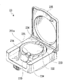
- FIG. 4A is a perspective view showing a circuit chamber forming a part of a blood circuit and a joint that realizes a connection to a pressure measuring device
- FIG. 4B is a perspective view showing the joint.
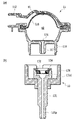
- FIG. 5 (a) is a vertical cross-sectional view showing a circuit chamber constituting a part of a blood circuit
- FIG. 5 (b) is a vertical cross-sectional view showing a joint that realizes connection of the circuit chamber to a pressure measuring device. ..
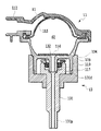
- FIG. 6 is a vertical sectional view showing a state in which a joint is connected to the circuit chamber shown in FIG.
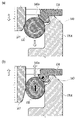
- FIG. 7 (a) is a vertical cross-sectional view of a main part for explaining a situation in which the circuit chamber shown in FIG. 5 is connected to a joint
- FIG. 7 (b) is a main point for explaining a situation when the circuit chamber is disconnected from the joint. It is a vertical sectional view of a section.
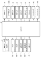
- FIG. 8 is a block diagram illustrating a connection configuration of a controller that controls the entire device.
- FIG. 9 is a schematic diagram showing a configuration of a main part during a connection work operation of a blood circuit.
- FIG. 10 is a schematic diagram showing a main configuration of another circuit chamber in a blood circuit.
- 11A and 11B are views showing another structure for connecting a joint to the circuit chamber, FIG. 11A is a cross-sectional view showing a state at the time of preparation for connection, and FIG. 11B is a cross-sectional view showing a state during connection operation.
- FIG. 1 to 9 are views showing a blood purification device which is an example of a medical device including the pressure measuring device according to the first embodiment of the present invention.
- the blood purification device M includes two sets of pressure measuring devices 1, a blood circuit 2, and a dialysis circuit 3, and responds to an input operation from an operation panel (operation unit) P. It is constructed in a medical device for performing dialysis treatment (blood purification treatment) of a patient by driving each part of the device including the blood circuit 2 and the dialysis circuit 3 based on the measurement result of each pressure measuring device 1.
- the blood circuit 2 includes an arterial side blood circuit 21 and a venous side blood circuit 22, and the blood pump 23 circulates the patient's blood so as to pass through the dialyzer 31.
- the dialysis circuit 3 is a dual pump together with a dialyzer 31 connecting the arterial side blood circuit 21 and the venous side blood circuit 22 of the blood circuit 2, and a dialysate introduction line 34 and a dialysate discharge line 35 connected to the dialyzer 31. 36 is provided to allow the dialysate in these lines 34, 35 to flow.
- the blood purification device M is manufactured in a structure in which the pressure measuring device 1 is detachably provided together with the dialysate introduction line 34, the dialysate discharge line 35, and the double pump 36 of the dialysis circuit 3, and is manufactured on the arterial side of the blood circuit 2.
- the dialyzer 31 of the dialysis circuit 3 is detachably attached and constructed so as to be used as a disposable item.
- the dialyzer 31 connects the dialysate introduction line 34 to the dialysate introduction port 31c and the dialysate discharge line 35 to the dialysate outlet 31d to supply the dialysate to the hollow thread (not shown) inside.
- a flow path to be flowed is formed, and the blood purification membrane of the hollow thread is used to perform dialysis treatment while passing the blood of the patient flowing through the blood circuit 2.
- the compound pump 36 is arranged so as to straddle both the dialysate introduction line 34 and the dialysate discharge line 35, and pumps the dialysate in both the introduction direction and the drainage direction so that the dialysate stably passes through the dialyzer 31. Drive to do.
- the dialysate introduction line 34 is connected to a dialysate supply device (not shown) at one end, and supplies the dialysate to the dialyzer 31 via the dialysate introduction port 31c on the other end while adjusting the concentration of the dialysate.
- the discharge line 35 is connected to one end side of the drainage means (not shown) and feeds out the dialysate that has been dialyzed through the dialysate outlet 31d on the other end side. Further, in the dialysate discharge line 35, a water removal pump 37 is arranged so as to bypass the double pump 36 so as to remove water from the patient's blood flowing through the dialyzer 31.
- the arterial blood circuit 21 of the blood circuit 2 is communicated by connecting one end side to the blood inlet 31a of the dialyzer 31 of the dialysis circuit 3 and piercing the patient's blood vessel with the arterial puncture needle 210 on the other end side.
- the blood to be dialyzed by the dialyzer 31 is processedly received (so-called blood removal).
- a pressure measuring device 1 and a blood pump 23 are installed in the middle of the circuit, and the pressure measuring device 1 measures the pressure according to the flow of blood in the circuit, while the blood pump 23 measures the pressure. Pump the blood so that it flows stably in the circuit.
- a connector 211 for connecting and connecting the arterial puncture needle 210 and a clamp 212 for adjusting and controlling the flow of blood in the circuit by opening and closing a valve are arranged.
- the blood circuit 2 (21, 22) is composed of an elastically deformable tube that fluidly accommodates fluid blood in an internal fluid flow path.
- the blood pump 23 pushes the blood in the fluid flow path to the downstream side by moving the portion of the blood circuit 2 that crushes the arterial blood circuit 21 in the form of a tube in the forward and reverse directions. It is configured as a so-called tube pump (ironing pump), and the fluid on the upstream side is continuously drawn by the negative pressure generated by the pumping of the fluid to the downstream side thereof.
- the blood pump 23 is manufactured in a structure in which a rotor 232 having a substantially disk shape is rotatably housed in a stator 231 having a circular concave shape, and is wound around the circular outer peripheral side of the rotor 232.
- the setting is such that the tubular arterial blood circuit 21 is sandwiched between the stator 231 and the circular inner wall surface 231s.
- a pair of rollers 233 are rotatably arranged in parallel with the rotation axis at symmetrical positions on the opposite side in the orthogonal direction (opposite side in the radial direction) of the axis of the disk-shaped rotor 232.
- the pair of rollers 233 presses the arterial blood circuit 21 against the circular inner wall surface 231s of the stator 231 to crush the inner surface of the tube so as to be closed tightly, and the blood pump 23 is driven to rotate along with the rotational drive of the rotor 232. It has become.
- the blood pump 23 can rotate the rotor 232 to pump the blood in the tube of the arterial blood circuit 21 to the downstream side, and in a state where the rotation of the rotor 232 is stopped, the inside of the circle of the stator 231.
- the roller 233 can crush the arterial blood circuit 21 on the wall surface 231s in a liquid-tight manner to stop the flow of blood in the tube.
- the blood pump 23 is provided with a cover 235 that covers the outer surface of the stator 231 and limits interference with the rotating rotor 232, the set arterial blood circuit 21, and the like, and is a cover that detects the opening and closing of the cover 235. It has a detection sensor 235s (shown in FIG. 8) to prevent the occurrence of an accident.
- guides 234 extending in the orthogonal direction (diameter direction) of the axis of the disk-shaped rotor 232 are installed at a total of four locations above and below the vicinity of the pair of rollers 233, and are wound around the rotor 232.
- the tubular arterial blood circuit 21 to be hung is prevented from coming off from the inside of the stator 231.
- the venous side blood circuit 22 of the blood circuit 2 is communicated by connecting one end side to the blood outlet 31b of the dialyzer 31 of the dialysis circuit 3 and piercing the patient's blood vessel with the venous side puncture needle 220 on the other end side.
- the blood after the dialysis treatment by the dialyzer 31 is returned to the patient side (so-called blood return).
- a pressure measuring device 1 and a venous chamber 225 are installed in the middle of the circuit, and the pressure measuring device 1 measures the pressure according to the flow of blood in the circuit while flowing by the blood pump 23.
- the venous chamber 225 separates the bubbles mixed in the blood on the venous side blood circuit 22 side (pumped) and returns normal blood safely to the patient.
- the vein-side blood circuit 22 has a connector 221 that connects and connects the vein-side puncture needle 220, a blood discrimination unit 222 that determines whether the fluid flowing in the circuit is blood, and a valve that controls the flow of blood in the circuit.
- a clamp 223 that is adjusted and controlled by opening and closing, and a bubble detection unit 224 that detects bubbles mixed in blood flowing in the circuit are arranged.
- the blood discrimination unit 222 may be provided on the arterial side blood circuit 21 side, or may be arranged on both of the blood circuits 21 and 22.
- the two sets of the pressure measuring device 1 are separately installed in each of the arterial side blood circuit 21 and the venous side blood circuit 22 of the blood circuit 2, depending on the flow of the patient's blood in the blood circuit 2. By detecting and measuring the fluctuating pressure as described later, it is possible to stably pump (flow) the blood of the patient on the arterial side and the venous side at the optimum pressure.
- the pressure measuring device 1 measures the pressure in the circuit chamber (detachable member) 11 detachably installed so as to be located in the middle of each flow path of the arterial blood circuit 21 and the venous blood circuit 22 of the blood circuit 2.
- the joint 13 is detachably attached to the circuit chamber 11 and the pressure sensor 15 is connected to the circuit chamber 11 for measurement.
- the circuit chamber 11 and the joint 13 are shown in a schematic diagram in FIG. 2 in a separated and connected state, they have a detachable structure so as to be integrated with the filter 116 interposed therebetween, as will be described later. It is made in.
- the joint 13 detects (measures) the pressure at which the spatial pressure in the circuit chamber 11 reaches the pressure sensor 15 and fluctuates due to the flow of blood in the blood circuit 2 by connecting the connecting tube 14C to the cylindrical protrusion 131p described later. )to enable.
- the circuit chamber 11 includes connection ports 112 and 113 communicating with the space S formed in the housing 111, and the blood circuit 2 (21, 22). ), The connection ports 112 and 113 are connected so that the space S is interposed in the middle thereof, thereby forming a part of a continuous fluid flow path via the dialyzer 31.
- This circuit chamber 11 is manufactured so that the diaphragm 115 is installed in the housing 111 and the space S is divided into the communication space S1 and the pressure space S2.
- the communication space S1 functions as a fluid flow path (blood flow path through which blood flows) communicating between the connection ports 112 and 113, and the pressure space S2 has a diaphragm according to the flow of blood in the communication space S1. It functions so that the volume varies as the 115 is deformed.
- the circuit chamber 11 includes an output port 117 that communicates with the pressure space S2 via the filter 116.
- the circuit chamber 11 is connected and fixed by inserting a cylindrical insertion joint 119 formed around the output port 117 into the cylindrical receiving joint 139 of the joint 13 described later, and the output port (connected portion) thereof. ) 117 is connected to the joint flow path (connection portion) 131 of the joint 13 to form an integrated structure.
- the filter 116 of the circuit chamber 11 prevents blood in the communication space S1 from flowing into the pressure space S2 and flowing out from the output port 117 into the joint 13 on the pressure sensor 15 side due to damage to the diaphragm 115 or the like. To prevent.
- the joint 13 is inserted by accommodating an O-ring 132 made of an elastic material in a large diameter portion 131d formed on one end side of a joint flow path (connection portion) 131.
- the O-ring 132 (the first contact surface of the circuit chamber 11) is closely sandwiched between the output port (connected portion) 117 and the outer surface of the circuit chamber 11 so as to be airtightly connected and connected (FIG. 7).
- a cap 134 made of an elastic material formed in a flat ring shape is installed on the end surface of the large diameter portion 131d on one end side of the joint flow path 131, and the cap 134 has a ring-shaped peripheral edge.
- a short flange 143 is formed and has an inner peripheral side slope 143s located on the inner peripheral side of the large diameter portion 131d of the joint flow path 131.
- the joint 13 is an O-ring that moves in the direction of the arrow F1 while being deformed between them when the insertion joint 119 of the circuit chamber 11 is pulled out from the joint flow path 131.
- the 132 is manufactured so as to prevent the flange 143 from coming off by abutting against the inner peripheral side slope 143s of the cap 134 and pressing the flange 143 against the inner surface of the large diameter portion 131d in the arrow F2 direction.
- the cap 134 can function as a stopper for the O-ring 132 from the large diameter portion 131d when the insertion joint 119 of the circuit chamber 11 is pulled out from the joint flow path 131.
- a cylindrical receiving joint 139 into which the insertion joint 119 of the circuit chamber 11 is inserted and fitted is fixed to the outside of the large diameter portion 131d on one end side of the joint flow path 131.
- a cylindrical protrusion 131p for connecting the connection tube 14C communicating with the pressure sensor 15 is formed on the other end side of the joint flow path 131.
- the joint 13 is integrated with the circuit chamber 11, and the output port 117 of the circuit chamber 11 is connected to the joint flow path 131 and communicated with the pressure sensor 15 via the connection tube (communication flow path) 14C. Has been realized.
- an engaging protrusion 118 is formed on the outer surface of the cylindrical insertion joint 119, and the joint 13 has an L-shaped crank groove 138 continuous from the opening side end side of the cylindrical receiving joint 139. It is formed.
- the circuit chamber 11 and the joint 13 have a cylindrical shaft by inserting the engagement protrusion 118 into the crank groove 138 and rotating the joint 13 relative to each other at the fitting position. It can be locked so that it cannot be pulled out just by moving it in the direction.
- the connecting tubes 14C1 and 14C2 are communicated and connected to the joint flow path 131 of the joint 13 integrated into the circuit chamber 11 of each blood circuit 2 (21, 22), respectively.
- a pair of branch tubes 14D1 and 14D2 and a common tube 14G are communicated with each other.
- one end side of the pair of branch tubes 14D1 and 14D2 is communicated and connected to the pair of connecting tubes 14C1 and 14C2 that are communicated and connected to the joint flow path 131 of the joint 13, and the branch tube is branched.
- the other ends of 14D1 and 14D2 are assembled and connected to one end of the common tube 14G to join them.
- the branch tube 14D1 is branched from the connection tube 14C1 in which the pressure sensor 15 is operably communicated and connected to the joint 13 integrated with the circuit chamber 11 on the arterial side blood circuit 21 side, and the branch tube 14D1 communicates with the common tube 14G on the way.
- a solenoid valve (opening / closing part) 161 that opens / closes the road is installed.
- the branch tube 14D2 is branched from the connection tube 14C in which the pressure sensor 15 on the venous side blood circuit 22 side is installed, and a solenoid valve 162 that opens and closes the communication flow path is installed on the way to the common tube 14G. ing.
- the common tube 14G has a pressurizing pump (pressurizing / depressurizing section) 17 that introduces pressurized air to the joint 13 side via the connecting tubes 14C1 and 14C2 on the opposite side (the other end side) of the branch tubes 14D1 and 14D2 on one end side.
- a pressure sensor 18 is operably installed in the middle of the flow path.
- the pressurizing pump 17 is provided with a filter 17f that prevents dust and the like from being mixed into the introduced air.
- the pressurizing pump 17 has a function of being driven in both forward rotation and reverse rotation to pressurize and depressurize the joint 13 side, but the present invention is not limited to this, and forward rotation (pressurization) or reverse rotation (decompression).
- a dedicated machine with only one function may be used. For example, when driving under reduced pressure, the fluid (air) to be flowed by the suction operation can be blown to a desired location in the same manner as the pressurized air described later.
- the pressurizing pump 17 is composed of a tube pump having the same function as the blood pump 23, and the roller 17r on the rotor side rotates while sandwiching the common tube 14G with the stator 17s and crushing the common tube 14G.
- pressurized air is sent to the joint 13 side of the blood circuit 2 (21, 22) via the branch tubes 14D1 and 14D2 and the connecting tubes 14C1 and 14C2.
- the blood pump 23 has the rotor side rollers 233 arranged at two equal intervals in the diametrical direction, whereas the rotor side rollers 17r are arranged at four equal intervals in the common tube.
- the 14G is crushed so as to be airtight on the stator 17s side.
- the pressurizing pump 17 pumps the air in the common tube 14G to the branch tubes 14D1 and 14D2 by rotating the rotor side roller 17r, and does not provide a valve when the rotation of the roller 17r is stopped.
- the common tube 14G can be closed so that it cannot be distributed.
- the blood of the patient is discharged through the arterial blood circuit 21 and the venous blood circuit 22, and the dialysate is dialyzed through the dialysate introduction line 34 and the dialysate discharge line 35.
- the dialysis treatment for purifying the blood of the patient is executed by controlling each part of the device including the blood pump 23, the compound pump 36, and the like by the controller 50 shown in FIG. 8 so as to pass through the 31 in parallel.
- the controller 50 is configured to include various memories such as RAM and ROM together with the CPU, and is based on detection information and storage parameters for acquiring a control program stored in advance in response to an input operation from the operation panel P. By executing it, various control processes including dialysis process are executed.
- the controller 50 is connected to the dialysis circuit 3 together with the clamp 212 and 223 installed in the blood circuit 2, the blood discrimination unit 222, the bubble detection unit 224, and the blood pump 23.
- Each part of the device including the installed double pump 36 and the water removal pump 37 is connected together with the operation panel P and the motion sensor 51 so that control signals and the like can be exchanged.
- the controller 50 controls the drive of each part of these devices based on the input operation from the operation panel P to control the patient's blood and dialysate.
- the patient is treated by performing a dialysis treatment for purifying the blood via the dialyzer 31 at a constant flow rate and pressure.
- the operation panel P includes various input operations of the blood purification device M, for example, an operation area for inputting and setting driving conditions and the like, and a display area for outputting and notifying the driving time and the like, together with a message prompting various operations.
- a user such as a nurse can operate a preparation button Pb or the like for starting / stopping a preparatory operation to be performed before starting the dialysis process described later.
- the controller 50 is also connected to the pressure sensors 15 and 18, the solenoid valves 161 and 162, and the pressurizing pump 17 so as to be able to exchange various signals and the like.
- the controller 50 detects the pressure in the pressure space (measurement target) S2 of the circuit chamber 11 communicating via the connecting tubes 14C1 and 14C2 by closing the solenoid valves 161 and 162, respectively, by the pressure sensor 15. Then, the pressure fluctuation in the communication space S1 of the circuit chamber 11 is acquired. Thereby, the controller 50 can grasp the blood flow quality of the patient in each of the arterial side blood circuit 21 and the venous side blood circuit 22 of the blood circuit 2, and for example, various messages are displayed and output on the operation panel P. Therefore, the dialysis treatment can be carried out safely and appropriately.
- the controller 50 opens the solenoid valves 161 and 162 while continuing the dialysis process in which the pressure in the pressure space S2 of the circuit chamber 11 is detected by the pressure sensor 15 and the pressure fluctuation in the communication space S1 is acquired. It also functions as a drive unit for driving the pressurizing pump 17.
- the controller 50 pressurizes the inside of the pressure space S2 of the circuit chamber 11 (pressurizes the outside air) through the branch tubes 14D1 and 14D2 and the common tube 14G by the pressure pump 17, and the amount of fluid (pressure) in the communication space S1. By changing the pressure, the flow amount and speed of the patient's blood are adjusted and controlled.
- the controller 50 detects the pressure in the common tube 14G by the pressure sensor 18 and pressurizes the pressure in the pressure space S2 of the circuit chamber 11 where the pressure sensor 15 detects the pressure, in other words, the circuit chamber 11.
- the pressurizing effect in the communication space S1 is acquired, and the pressurizing pump 17 is adjusted and controlled so as to be optimally driven.
- a set of pressure pumps 17 is installed to adjust and control the flow amount and speed of the patient's blood in the communication space S1 of the circuit chamber 11 will be described as an example, but the present invention is limited to this. Needless to say, it may be installed in each of the arterial side blood circuit 21 and the venous side blood circuit 22 of the blood circuit 2 so that it can be adjusted and controlled separately.
- the controller 50 when preparing the dialysis process of the blood flowing through the blood circuit 2 (21, 22), the controller 50 follows a preparation button according to a message prompting the preparation operation of the operation panel P before connecting the circuit chamber 11 to the joint 13.
- a circuit connection preparation operation described later is performed to blow off foreign matter adhering to the O-ring 132 of the joint flow path 131 of the joint 13.
- the controller 50 opens the solenoid valves 161 and 162 and drives the pressurizing pump 17 in response to the pressing of the preparation button Pb, for example, as schematically shown in FIG. 9, the various tubes 14C1 and the like.
- the inside of the pressure space S2 of the circuit chamber 11 communicating via 14C2, 14D1, 14D2, 14G is pressurized to a desired pressure (outside air is pumped).
- the controller 50 closes the solenoid valves 161 and 162 and stops driving the pressurizing pump 17 to stand by.
- the controller 50 can perform a circuit connection preparation operation for ejecting air from the joint flow path 131 of the joint 13 before connecting the circuit chamber 11.
- the controller 50 presses the pressure pump 17 so that the pressure sensor 18 detects and measures the pressure in the common tube 14G, which is pressurized to the extent that foreign matter adhering to the O-ring 132 of the joint flow path 131 of the joint 13 is blown away. Is designed to drive. As described above, since the pressure sensor 18 is different from the pressure sensor 15 that detects and measures the pressure in the pressure space S2 that fluctuates due to the flow of blood flowing in the communication space S1 of the circuit chamber 11, the controller 50 is the pressure sensor 15. , 18 measurement ranges are appropriately adjusted to measure pressure.
- the pressure measuring device 1 presses the preparation button Pb of the operation panel P when performing the preparatory work for connecting the circuit chamber 11 to the joint 13 in order to carry out the dialysis process of the patient's blood flowing through the blood circuit 2.
- the pressure pump 17 is driven to eject air from the joint flow path 131 of the joint 13, and the receiving joint 139 is inserted into the insertion joint 119 to be airtightly connected.
- the blood purification device M can blow the pressurized air of the pressurizing pump 17 to the O-ring 132 in the large diameter portion 131d of the joint flow path 131 of the joint 13 to blow off the adhering foreign matter.
- the blood purification device M sandwiches a foreign substance between the O-ring 132 of the joint flow path 131 of the joint 13 and the outer surface of the output port 117 of the circuit chamber 11, and a leak occurs in the pressure space S2, so that the circuit chamber 11 It is possible to prevent the pressure fluctuation according to the flow of blood flowing in the communication space S1 from becoming unmeasurable.
- the joint 13 of the pressure measuring device 1 is continuously connected to the circuit chamber 11, and the pressure fluctuation in the pressure space S2 of the circuit chamber 11 is highly accurate by the pressure sensor 15. Can be detected and measured.
- the blood purification device M can adjust the blood flow in the blood circuit 2 with high accuracy, and can purify the patient's blood by dialysis treatment with a reliable and stable flow.
- the circuit chamber 11 is liquidtightly divided into a communication space S1 communicating with the blood circuit 2 and a pressure space S2 communicating with the joint flow path 131 of the joint 13 by the diaphragm 115 of the diaphragm.
- the type (so-called pressure pod) will be described as an example, but the description is not limited to this.
- a so-called air trap type circuit chamber 1011 in which the diaphragm 115 is omitted and has one internal space S is a blood circuit 21 on the arterial side and a blood circuit 22 on the venous side, respectively. It can also be applied to the blood circuit 2 installed in.
- the circuit chamber 1011 constitutes a part of the blood circuit 2 in such a form that the flowing blood flows in from the gas phase side in the upper part of the internal space S and flows out from the liquid phase side in the lower part of the internal space S. It is made in.
- the circuit chamber 1011 has an output port 117 and a plug-in joint 119 located on the upper side of the internal space S, and is inserted into the receiving joint 139 of the joint 13 so as to communicate with the joint flow path 131.
- the pressure in the internal space S of the circuit chamber 1011 without the diaphragm 115 may be detected by the pressure sensor 15 to acquire the pressure fluctuation in the blood circuit 2 (21, 22). It is possible to grasp the flow quality of the patient's blood and carry out the dialysis treatment safely and appropriately.
- the gas phase pressure in the internal space S of the circuit chamber 1011 is detected by the pressure sensor 15 while the dialysis process is continued, and the pressurizing pump 17 is driven according to the pressure fluctuation.
- the inside of the internal space S can be pressurized (outside air is pumped) to change the liquid level at the boundary between the gas phase and the liquid phase, and the flow amount and speed of the patient's blood can be adjusted and controlled.
- the cover 235 of the blood pump 23 is opened and closed instead of pressing the preparation button Pb of the operation panel P in the above-described embodiment, and the arterial blood circuit.
- the circuit connection preparation operation in the above-described embodiment is performed.
- the controller 50 starts driving the pressurizing pump 17 with the opening of the solenoid valves 161 and 162 at the timing when the cover 235 of the blood pump 23 is opened and closed and the setting of the arterial blood circuit 21 is completed. After this, the controller 50 measures the elapsed time from the start time, and confirms the elapsed drive time, for example, the working time that can sufficiently perform the work of connecting the circuit chamber 11 to the joint 13. At the same timing, the solenoid valves 161 and 162 are closed and the pressurizing pump 17 is stopped.
- the pressure measuring device 1 can surely perform the preparatory work for airtightly connecting the circuit chamber 11 of the blood circuit 2 to the joint 13 with high quality and high reliability, and after the preparatory work.
- the pressure pump 17 can be automatically stopped to prevent the common tube 14G and the like from being consumed by the narrowing operation of the roller 17r.
- the pressure pump 17 of the pressure measuring device 1 can reduce the load due to the circuit connection preparation operation, and is around the pressure pump 17 including the common tube 14G. It is possible to reduce the consumption of various parts and drive them stably.
- a blood purification device which is an example of a medical device including the pressure measuring device according to the third embodiment of the present invention will be described.
- the motion sensor 51 operates the operation panel P or the blood pump instead of pressing the preparation button Pb of the operation panel P in the above-described embodiment.
- the circuit connection preparation operation in the above-described embodiment is performed.
- the controller 50 starts driving the pressurizing pump 17 with the opening of the solenoid valves 161 and 162 at the timing when the human sensor 51 detects the user in front of the blood purification device M, as in the above embodiment.
- the solenoid valves 161 and 162 are closed and added at the timing when it is confirmed that the elapsed time measured from the start time exceeds, for example, the work time sufficient for connecting the circuit chamber 11 to the joint 13.
- the drive of the pressure pump 17 is stopped.
- the pressure pump 17 of the pressure measuring device 1 can reduce the load due to the circuit connection preparation operation as in the above-described embodiment, and the common tube 14G can be used. It is possible to reduce the consumption of various parts around the pressurizing pump 17 including the pressurizing pump 17 and stably drive the pump.
- the controller 50 of the blood purification device M drives the pressurizing pump 17 in a shutoff state in which the solenoid valves 161 and 162 are closed when the circuit connection preparation operation in the above embodiment is performed.
- the solenoid valves 161 and 162 are closed. Open and switch to the communication state.
- the controller 50 closes the solenoid valves 161 and 162 at the timing when it is confirmed that the pressurizing pressure in the pressure space S2 of the circuit chamber 11 detected by the pressure sensor 15 has reached the preset end pressure.
- the drive of the pressurizing pump 17 is stopped.
- the pressure measuring device 1 drives the pressurizing pump 17 to eject the compressed air stored in the common tube 14G from the joint flow path 131 of the joint 13, and the O-ring 132. Foreign matter adhering to the air can be effectively blown off, and the pressurizing pump 17 is automatically stopped by reliably judging the completion of connection to prevent the common tube 14G and the like from being consumed by the narrowing operation of the roller 17r. Can be done.
- a blood purification device which is an example of a medical device including the pressure measuring device according to the fifth embodiment of the present invention will be described.
- the solenoid valves 161 and 162 are opened and the pressurizing pump 17 rotates in the forward direction (addition). Pressure) drive and reverse (decompression) drive are repeated at regular intervals. After that, the controller 50 closes the solenoid valves 161 and 162 and stops the driving of the pressurizing pump 17 at the timing when the lapse of the set working time (driving time) is confirmed from the start time.
- the pressure measuring device 1 repeats the forward rotation drive and the reverse rotation drive of the pressurizing pump 17 in addition to the operation according to the above-described embodiment, and intermittently applies compressed air to the O-ring 132 of the joint flow path 131 of the joint 13. While spraying, the vicinity of the O-ring 132 can be sucked intermittently, and foreign matter adhering to the O-ring 132 can be effectively peeled off.
- the blood purification device M enables the pressure measuring device 1 to function by communicating the joint 13 with the circuit chamber 11 installed in the blood circuit 2.
- the communication structure is formed so that the joint flow path 1131 of the joint 13 is inserted into the output port 1117 communicating with the pressure space S2 of the circuit chamber 11.
- the joint flow path 1131 of the joint 13 is formed in a conical base shape, and the output port 1117 of the circuit chamber 11 replaces the receiving joint 139 of the above-described embodiment with the conical base of the joint flow path 1131. It is formed in the shape of a joint having an inner surface into which the is fitted.
- the joint flow path 1131 and the output port 1117 are formed so as to sandwich the O-ring 1132 between the conical bases on the outer surface and the inner surface to be fitted to each other so as to be airtightly connected and joined.
- the pressurized air of the pressurizing pump 17 can be blown to the output port 1117 side and the O-ring 1132 side of the joint flow path 1131 to blow off the adhering foreign matter.
- the pressurized air pumped by the pressurizing pump 17 is blown into the output port 1117 immediately before the connection with the output port 1117 of the circuit chamber 11 while being ejected from the joint flow path 1131 side of the joint 13. It can be blown back, and foreign matter adhering to the O-ring 1132 can be strongly blown off through a narrow gap between the joint flow path 1131 and the joint flow path 1131.
- the blood purification device M sandwiches a foreign substance between the O-ring 132 of the joint flow path 1131 of the joint 13 and the output port 1117 of the circuit chamber 11, and a leak occurs in the pressure space S2, so that the circuit chamber 11 communicates with the blood purification device M. It is possible to more effectively prevent the pressure fluctuation according to the flow of blood flowing in the space S1 from becoming unmeasurable.
- the joint 13 of the pressure measuring device 1 can be connected and connected with high quality without sandwiching foreign matter in the circuit chamber 11, and the pressure fluctuation in the pressure space S2 of the circuit chamber 11 is detected and measured with high accuracy by the pressure sensor 15. can do.
- the blood purification device M can adjust the blood flow in the blood circuit 2 with high accuracy, and can purify the patient's blood by dialysis treatment with a reliable and stable flow.
- a communication installed so that gas can flow between the detachable member (circuit chamber 11) provided with a fluid flow path (blood circuit 2) through which fluid can flow, and the fluid flow path of the detachable member as a measurement target.
- Pressure measurement including a flow path 131) and a pressure sensor (15, 18) for measuring the pressure in the fluid flow path and the communication flow path when the fluid flow path and the communication flow path are in a communication state.
- a pressurizing / depressurizing unit (pressurizing pump 17) that pressurizes or depressurizes the inside of the communication flow path via branch tubes 14D1 and 14D2 and a common tube 14G so as to release or suck gas to the outside. And, at the timing when the first contact surface (O-ring 132) of the connecting portion that is in close contact with the connected portion of the detachable member is separated from the connected portion, the pressurizing / depressurizing portion is manually or automatically driven.
- connection portion has a drive unit (controller 50) to be operated, and the connection portion is attracted to a place where gas is released or a gas is sucked by pressurization or depressurization of the pressurization / depressurization portion in a state of eliminating communication away from the connected portion.
- a pressure measuring device in which a first contact surface is formed at a location where a first contact surface is formed.
- the communication flow path includes an opening / closing section (sodium valves 161 and 162) that switches between the pressurizing / depressurizing section and the measurement target in a communicating state or a shut-off state, and the opening / closing section is in the shut-off state.
- the pressure measuring device according to "1" or "2", wherein after pressurizing or depressurizing the inside of the flow path, the communication state is switched and gas is blown onto the first contact surface of the connection portion.
- the pressurizing / depressurizing unit has a function of reverse driving to depressurize the inside of the communication flow path in addition to the forward rotation drive to pressurize the inside of the communication flow path, any one of "1" to "3".
- the pressure measuring device according to the section.
- the pressure measuring device according to any one of “1" to “4" above is provided, and the detachable member is a blood flow path (blood circuit 2) through which blood can flow as the fluid flow path.
- a medical device comprising a chamber (circuit chamber 11) capable of storing blood and gas as a part of the blood flow path, and the measurement target is the internal space (pressure space S2) of the chamber.
- Purifier M The pressure measuring device according to any one of “1" to “4" above is provided, and the detachable member is a blood flow path (blood circuit 2) through which blood can flow as the fluid flow path.
- a medical device comprising a chamber (circuit chamber 11) capable of storing blood and gas as a part of the blood flow path, and the measurement target is the internal space (pressure space S2) of the chamber.
- Purifier M Purifier
- the pressurizing / depressurizing portion is formed on the first contact surface of the connecting portion and the second contact surface of the connected portion immediately before the connecting portion approaches the connected portion on the chamber side.
- the medical device according to any one of "5" to "7", wherein the gas is released or sucked toward both sides.
- pressure air or suction is applied to the first contact surface in contact with the connected portion before connecting the fluid flow path whose pressure fluctuates and the communication flow path. It can blow air to effectively blow off foreign matter, and can connect with high quality and reliability.
- pressure air or suction air is effectively applied to the first contact surface in contact with the connected portion before connecting the fluid flow path whose pressure fluctuates and the communication flow path. It is possible to blow off foreign matter more reliably by spraying it on the air, and it is possible to connect with high quality and reliability.
- the operation unit can be operated to drive the pressurizing / depressurizing unit to stop, and it is possible to prevent the parts from being unnecessarily consumed.
- the pressurizing / depressurizing unit can be automatically stopped, and it is possible to more reliably prevent the parts from being consumed.
- compressed air or suction air can be blown into the narrow gap between the connecting part and the connected part on the chamber side, and foreign matter can be blown off more reliably to communicate with high quality and reliability. You can connect.
- the medical device described above will be described as an example of a blood purification device (dialysis device) for flowing a fluid (liquid) of blood, but the present invention is not limited to this, and for example, breathing air (gas) is described. It goes without saying that it can also be applied to an artificial heart-lung machine that supplies and exhausts fluids such as).
- a blood purification device dialysis device
- breathing air gas
- the circuit connection preparation operation when connecting the joint 13 to the circuit chamber 11 will be mainly described, but in addition to or in place of this operation, the joint flow of the joint 13 will be described in advance.
- the operation of ejecting (or sucking) air from the road 131 may be performed regularly or irregularly. In this case, even in a state where the circuit chamber 11 is connected and the blood circuit 2 is not attached, it is possible to prevent foreign matter from adhering to and accumulating at the connecting portion of the joint 13 connected to the circuit chamber 11. It is possible to maintain and maintain the state of the device soundly.
Landscapes
- Health & Medical Sciences (AREA)
- Heart & Thoracic Surgery (AREA)
- Vascular Medicine (AREA)
- Life Sciences & Earth Sciences (AREA)
- General Health & Medical Sciences (AREA)
- Anesthesiology (AREA)
- Biomedical Technology (AREA)
- Hematology (AREA)
- Cardiology (AREA)
- Animal Behavior & Ethology (AREA)
- Engineering & Computer Science (AREA)
- Public Health (AREA)
- Veterinary Medicine (AREA)
- Physics & Mathematics (AREA)
- General Physics & Mathematics (AREA)
- External Artificial Organs (AREA)
- Measuring Fluid Pressure (AREA)
Abstract
Description
図1および図2において、血液浄化装置Mは、2組の圧力測定装置1と、血液回路2と、透析回路3と、を備えて、操作パネル(操作部)Pからの入力操作に応じて圧力測定装置1毎の測定結果に基づいて血液回路2および透析回路3を含む装置各部を駆動して患者の透析治療(血液浄化処理)を行う医療装置に構築されている。血液回路2は、動脈側血液回路21と、静脈側血液回路22と、を備えて、血液ポンプ23によって、ダイアライザ31を経由するように患者の血液を循環させる。透析回路3は、血液回路2の動脈側血液回路21および静脈側血液回路22を接続するダイアライザ31と、このダイアライザ31に接続する透析液導入ライン34および透析液排出ライン35の2系統と共に複式ポンプ36を備えて、これらライン34、35内の透析液を流動させる。この血液浄化装置Mは、透析回路3の透析液導入ライン34、透析液排出ライン35および複式ポンプ36と共に、圧力測定装置1を着脱不能に備える構造に作製されており、血液回路2の動脈側血液回路21および静脈側血液回路22と共に、透析回路3のダイアライザ31を着脱可能に装着して使い捨て使用されるように構築されている。
このように、本実施形態の血液浄化装置Mにおいては、圧力測定装置1のジョイント13を回路チャンバ11に連通接続して、その回路チャンバ11の圧力空間S2における圧力変動を圧力センサ15により高精度に検出測定することができる。
ここで、本実施形態においては、回路チャンバ11が血液回路2に連通する連通空間S1とジョイント13の継手流路131に連通する圧力空間S2とに隔膜のダイヤフラム115により液密に区分されているタイプ(所謂、圧ポッド)を一例に説明するがこれに限るものではない。例えば、図10に他の態様として示すように、ダイヤフラム115が省略されて1つの内部空間Sを備える、所謂、エアトラップタイプの回路チャンバ1011が動脈側血液回路21および静脈側血液回路22のそれぞれに設置される血液回路2に適用することもできる。
次に、本発明の第2実施形態に係る圧力測定装置を備える医療装置の一例である血液浄化装置を説明する。ここで、本実施形態は、上述実施形態と略同様に構成されていることから図面を流用して、同様の構成には同一の符号を付して特徴部分を説明する(以下で説明する他の実施形態においても同様)。
このように、本実施形態の血液浄化装置Mにおいては、圧力測定装置1の加圧ポンプ17が回路接続準備動作に伴う負荷を低減することができ、共通チューブ14Gを含む加圧ポンプ17周りの各種部品の消耗を低減して安定駆動させることができる。
次に、本発明の第3実施形態に係る圧力測定装置を備える医療装置の一例である血液浄化装置を説明する。
このように、本実施形態の血液浄化装置Mにおいても、上述実施形態と同様に、圧力測定装置1の加圧ポンプ17が回路接続準備動作に伴う負荷を低減することができ、共通チューブ14Gを含む加圧ポンプ17周りの各種部品の消耗を低減して安定駆動させることができる。
次に、本発明の第4実施形態に係る圧力測定装置を備える医療装置の一例である血液浄化装置を説明する。
このように、本実施形態の血液浄化装置Mにおいては、上述実施形態による効果に加えて、血液回路2における回路チャンバ11の出力ポート117をジョイント13の継手流路131に連通接続する作業を高品質かつ信頼性高く行うことができ、共通チューブ14Gを含む加圧ポンプ17周りの各種部品の消耗を低減して安定駆動させることができる。
次に、本発明の第5実施形態に係る圧力測定装置を備える医療装置の一例である血液浄化装置を説明する。
このように、本実施形態の血液浄化装置Mにおいては、上述実施形態による効果に加えて、血液回路2における回路チャンバ11の出力ポート117をジョイント13の継手流路131に連通接続する作業を高品質かつ信頼性高く行うことができる。
次に、図11を加えて、本発明の第6実施形態に係る圧力測定装置を備える医療装置の一例である血液浄化装置を説明する。
このように、本実施形態の血液浄化装置Mにおいても、上述実施形態と同様の作用効果を得ることができ、回路チャンバ11の出力ポート1117とジョイント13の継手流路1131との間の狭い隙間から圧力空気を噴出させてOリング1132(第1の接触面)と共に、そのOリング1132が密接する出力ポート1117の円錐台内面(第2の接触面)にも付着する異物を強力に吹き飛ばすことができる。
次に、以上説明した実施形態における符号などを援用して、本件発明を構成する発明特定事項を連記する。なお、下記の各符号などは、特許請求の範囲における構成要素を実施形態の記載を援用して説明するに過ぎず、その構成要素を具体的な部材等に限定するものではないことは言うまでもない。
2……血液回路
3……透析回路
11、1011……回路チャンバ
13……ジョイント
14C、14C1、14C2……接続チューブ
14D1、14D2……分岐チューブ
14G……共通チューブ
15、18……圧力センサ
17……加圧ポンプ
17r、233……ローラ
17s、231……ステータ
21……動脈側血液回路
22……静脈側血液回路
23……血液ポンプ
31……ダイアライザ
50……コントローラ
51……人感センサ
115……ダイヤフラム
116……フィルタ
117、1117……出力ポート
119……差込継手
131、1131……継手流路
132、1132……Oリング
134……キャップ
139……受け継手
143……フランジ
143s……内周側斜面
161、162……ソレノイドバルブ
210……動脈側穿刺針
220……静脈側穿刺針
235……カバー
235s……カバー検出センサ
M……血液浄化装置
P……操作パネル
Pb……準備ボタン
S……内部空間
S1……連通空間
S2……圧力空間
Claims (9)
- 流体が流通可能な流体流路を備える着脱部材が着脱されると共に、当該着脱部材を測定対象として圧力を測定する圧力測定装置であって、
前記流体流路との間で気体を流通可能に設置される連通流路と、
前記流体流路および前記連通流路が連通状態または連通解消状態になるように、前記着脱部材の被接続部が接続される接続部と、
前記被接続部が前記接続部に接続されて前記流体流路および前記連通流路が前記連通状態であるとき、前記流体流路および前記連通流路内の圧力を測定する圧力センサと、
外部に気体を放出または吸引させるように前記連通流路内を加圧または減圧する加減圧部と、
前記被接続部に気密に接触させる前記接続部の第1の接触面が前記被接続部から離間しているタイミングに、手動または自動で前記加減圧部を駆動させる駆動部と、を有し、
前記接続部は、前記被接続部から離間する前記連通解消状態で前記加減圧部の加圧または減圧により気体が放出される箇所または気体が吸引される箇所に前記第1の接触面が形成されている、圧力測定装置。 - 前記接続部は、前記第1の接触面が前記被接続部に気密に密着可能である弾性材料で作製されている、請求項1に記載の圧力測定装置。
- 前記連通流路は、前記加減圧部と前記測定対象との間を連通状態または遮断状態に切り替える開閉部を備え、
前記開閉部は、遮断状態で前記連通流路内を加圧または減圧した後に連通状態に切り替えて前記接続部の前記第1の接触面に気体を吹き付ける、請求項1または請求項2に記載の圧力測定装置。 - 前記加減圧部は、前記連通流路内を加圧する正転駆動に加えて、前記連通流路内を減圧する逆転駆動する機能を備える、請求項1から請求項3のいずれか1項に記載の圧力測定装置。
- 請求項1から請求項4のいずれか1項に記載の圧力測定装置を有し、
前記流体流路は、血液が流通可能な血液流路であり、
前記着脱部材は、前記血液流路の一部として、血液および気体を貯留可能なチャンバを備え、
前記測定対象が、前記チャンバの内部空間である、医療装置。 - 前記加減圧部の駆動を操作する操作部を有する、請求項5に記載の医療装置。
- 前記駆動部は、操作するユーザの検知または前記ユーザによる操作の検知を確認したときに、前記加減圧部の駆動を自動的に開始させる、請求項5または請求項6に記載の医療装置。
- 前記駆動部は、前記圧力センサの測定値が予め設定されている所定圧力に達したタイミングに前記加減圧部の駆動を自動的に停止させる、請求項5から請求項7のいずれか1項に記載の医療装置。
- 前記加減圧部は、前記接続部が前記被接続部に接近する接続直前に、前記接続部の前記第1の接触面および前記被接続部の第2の接触面の双方との間で気体を放出または吸引する、請求項5から請求項7のいずれか1項に記載の医療装置。
Priority Applications (3)
| Application Number | Priority Date | Filing Date | Title |
|---|---|---|---|
| US18/257,354 US20240100235A1 (en) | 2020-12-21 | 2021-12-06 | Pressure measuring device and medical device |
| CN202180084404.1A CN116669783B (zh) | 2020-12-21 | 2021-12-06 | 压力测定装置和医疗装置 |
| EP21910259.7A EP4265282B1 (en) | 2020-12-21 | 2021-12-06 | Pressure measuring device and medical device |
Applications Claiming Priority (2)
| Application Number | Priority Date | Filing Date | Title |
|---|---|---|---|
| JP2020-211632 | 2020-12-21 | ||
| JP2020211632A JP7189925B2 (ja) | 2020-12-21 | 2020-12-21 | 圧力測定装置および医療装置 |
Publications (1)
| Publication Number | Publication Date |
|---|---|
| WO2022138109A1 true WO2022138109A1 (ja) | 2022-06-30 |
Family
ID=82159575
Family Applications (1)
| Application Number | Title | Priority Date | Filing Date |
|---|---|---|---|
| PCT/JP2021/044720 Ceased WO2022138109A1 (ja) | 2020-12-21 | 2021-12-06 | 圧力測定装置および医療装置 |
Country Status (5)
| Country | Link |
|---|---|
| US (1) | US20240100235A1 (ja) |
| EP (1) | EP4265282B1 (ja) |
| JP (2) | JP7189925B2 (ja) |
| CN (1) | CN116669783B (ja) |
| WO (1) | WO2022138109A1 (ja) |
Families Citing this family (1)
| Publication number | Priority date | Publication date | Assignee | Title |
|---|---|---|---|---|
| CN116999041B (zh) * | 2023-09-07 | 2024-05-03 | 南京汉科明德医疗科技有限公司 | 一种无接触回输压监测系统及监测方法 |
Citations (4)
| Publication number | Priority date | Publication date | Assignee | Title |
|---|---|---|---|---|
| JP2017504389A (ja) * | 2013-12-23 | 2017-02-09 | フレセニウス メディカル ケア ホールディングス インコーポレーテッド | 圧力ポッドダイヤフラムの自動検出及び調整 |
| JP2019124636A (ja) * | 2018-01-18 | 2019-07-25 | 日機装株式会社 | 圧力検出器の調整装置 |
| JP2020089588A (ja) | 2018-12-06 | 2020-06-11 | 日機装株式会社 | シール部材の押さえ構造、血液浄化装置及びキャップ |
| WO2020250839A1 (ja) * | 2019-06-12 | 2020-12-17 | 日機装株式会社 | 圧力検出装置及びそれを用いた血液浄化装置 |
Family Cites Families (9)
| Publication number | Priority date | Publication date | Assignee | Title |
|---|---|---|---|---|
| JPH10297618A (ja) * | 1997-04-25 | 1998-11-10 | Snow Brand Milk Prod Co Ltd | 異物除去装置及びこれを備えた充填機 |
| JP2002085295A (ja) * | 2000-09-16 | 2002-03-26 | Masayoshi Furuichi | 循環気流型、電気掃除機 |
| JP5778004B2 (ja) * | 2011-11-14 | 2015-09-16 | 日機装株式会社 | 血液浄化装置 |
| TWD163865S (zh) * | 2013-06-19 | 2014-11-01 | 李辰筠 | 瓶子 |
| DE102015102040A1 (de) * | 2015-02-12 | 2016-08-18 | Fresenius Medical Care Deutschland Gmbh | Verfahren zum Überprüfen eines Verbindungszustandes einer Blutbehandlungsvorrichtung mit einem Blutschlauchsatz, sowie Vorrichtungen |
| JP6685089B2 (ja) * | 2015-06-01 | 2020-04-22 | 日機装株式会社 | 医療用液圧検出装置 |
| WO2017039213A1 (ko) * | 2015-09-04 | 2017-03-09 | 주식회사 포스코 | 이물질 제거장치 |
| CN206998733U (zh) * | 2017-07-11 | 2018-02-13 | 青岛安装建设股份有限公司 | 一种燃气管道法兰安装工装 |
| KR101992083B1 (ko) * | 2019-02-20 | 2019-10-02 | 장현실 | 스마트 도로결빙방지시스템 및 그 설치공법 |
-
2020
- 2020-12-21 JP JP2020211632A patent/JP7189925B2/ja active Active
-
2021
- 2021-12-06 WO PCT/JP2021/044720 patent/WO2022138109A1/ja not_active Ceased
- 2021-12-06 EP EP21910259.7A patent/EP4265282B1/en active Active
- 2021-12-06 US US18/257,354 patent/US20240100235A1/en active Pending
- 2021-12-06 CN CN202180084404.1A patent/CN116669783B/zh active Active
-
2022
- 2022-12-02 JP JP2022193371A patent/JP7690442B2/ja active Active
Patent Citations (4)
| Publication number | Priority date | Publication date | Assignee | Title |
|---|---|---|---|---|
| JP2017504389A (ja) * | 2013-12-23 | 2017-02-09 | フレセニウス メディカル ケア ホールディングス インコーポレーテッド | 圧力ポッドダイヤフラムの自動検出及び調整 |
| JP2019124636A (ja) * | 2018-01-18 | 2019-07-25 | 日機装株式会社 | 圧力検出器の調整装置 |
| JP2020089588A (ja) | 2018-12-06 | 2020-06-11 | 日機装株式会社 | シール部材の押さえ構造、血液浄化装置及びキャップ |
| WO2020250839A1 (ja) * | 2019-06-12 | 2020-12-17 | 日機装株式会社 | 圧力検出装置及びそれを用いた血液浄化装置 |
Non-Patent Citations (1)
| Title |
|---|
| See also references of EP4265282A4 |
Also Published As
| Publication number | Publication date |
|---|---|
| CN116669783B (zh) | 2026-03-10 |
| EP4265282A4 (en) | 2024-12-25 |
| JP2022098218A (ja) | 2022-07-01 |
| JP7189925B2 (ja) | 2022-12-14 |
| US20240100235A1 (en) | 2024-03-28 |
| JP2023016916A (ja) | 2023-02-02 |
| EP4265282B1 (en) | 2026-02-25 |
| EP4265282A1 (en) | 2023-10-25 |
| JP7690442B2 (ja) | 2025-06-10 |
| CN116669783A (zh) | 2023-08-29 |
Similar Documents
| Publication | Publication Date | Title |
|---|---|---|
| US9821107B2 (en) | Dialysis systems and methods | |
| US9220832B2 (en) | Dialysis systems and methods | |
| CN101511404B (zh) | 血液处理装置和用于排空血液处理装置的血液软管组的方法 | |
| US7981280B2 (en) | Recirculation of blood in an extracorporeal blood treatment system | |
| US9872951B2 (en) | Blood purification apparatus and priming method for the same | |
| US9844620B2 (en) | Blood set component connection detection | |
| US10314957B2 (en) | Blood purification apparatus | |
| US10357600B2 (en) | Extracorporeal blood treatment system, disposable set and valve unit for pre/post infusion | |
| US10058692B2 (en) | Connector for dialyzer | |
| CN107614032B (zh) | 医疗用液压检测装置 | |
| JPS61203973A (ja) | 血液透析ろ過装置 | |
| US10406273B2 (en) | Blood purification apparatus | |
| US10576197B2 (en) | Blood purification device and priming method | |
| US12161786B2 (en) | Dialysis transfer set having filter integrity testing | |
| JP7690442B2 (ja) | 圧力測定装置および医療装置 | |
| US11554202B2 (en) | Blood purification apparatus and method of discharging bubbles therefrom | |
| US20240115779A1 (en) | Apparatus for extracorporeal blood treatment | |
| US20190231959A1 (en) | Dialysis device | |
| JPH0244760Y2 (ja) |
Legal Events
| Date | Code | Title | Description |
|---|---|---|---|
| 121 | Ep: the epo has been informed by wipo that ep was designated in this application |
Ref document number: 21910259 Country of ref document: EP Kind code of ref document: A1 |
|
| WWE | Wipo information: entry into national phase |
Ref document number: 18257354 Country of ref document: US Ref document number: 202180084404.1 Country of ref document: CN |
|
| WWE | Wipo information: entry into national phase |
Ref document number: 2021910259 Country of ref document: EP |
|
| NENP | Non-entry into the national phase |
Ref country code: DE |
|
| ENP | Entry into the national phase |
Ref document number: 2021910259 Country of ref document: EP Effective date: 20230721 |
|
| WWG | Wipo information: grant in national office |
Ref document number: 2021910259 Country of ref document: EP |