WO2022138128A1 - 表示装置 - Google Patents
表示装置 Download PDFInfo
- Publication number
- WO2022138128A1 WO2022138128A1 PCT/JP2021/044864 JP2021044864W WO2022138128A1 WO 2022138128 A1 WO2022138128 A1 WO 2022138128A1 JP 2021044864 W JP2021044864 W JP 2021044864W WO 2022138128 A1 WO2022138128 A1 WO 2022138128A1
- Authority
- WO
- WIPO (PCT)
- Prior art keywords
- display panel
- woofer
- display device
- actuator
- vibration
- Prior art date
- Legal status (The legal status is an assumption and is not a legal conclusion. Google has not performed a legal analysis and makes no representation as to the accuracy of the status listed.)
- Ceased
Links
Images




Classifications
-
- H—ELECTRICITY
- H04—ELECTRIC COMMUNICATION TECHNIQUE
- H04R—LOUDSPEAKERS, MICROPHONES, GRAMOPHONE PICK-UPS OR LIKE ACOUSTIC ELECTROMECHANICAL TRANSDUCERS; ELECTRIC HEARING AIDS; PUBLIC ADDRESS SYSTEMS
- H04R1/00—Details of transducers, loudspeakers or microphones
- H04R1/02—Casings; Cabinets ; Supports therefor; Mountings therein
- H04R1/025—Arrangements for fixing loudspeaker transducers, e.g. in a box, furniture
-
- H—ELECTRICITY
- H04—ELECTRIC COMMUNICATION TECHNIQUE
- H04R—LOUDSPEAKERS, MICROPHONES, GRAMOPHONE PICK-UPS OR LIKE ACOUSTIC ELECTROMECHANICAL TRANSDUCERS; ELECTRIC HEARING AIDS; PUBLIC ADDRESS SYSTEMS
- H04R5/00—Stereophonic arrangements
- H04R5/02—Spatial or constructional arrangements of loudspeakers
-
- H—ELECTRICITY
- H04—ELECTRIC COMMUNICATION TECHNIQUE
- H04R—LOUDSPEAKERS, MICROPHONES, GRAMOPHONE PICK-UPS OR LIKE ACOUSTIC ELECTROMECHANICAL TRANSDUCERS; ELECTRIC HEARING AIDS; PUBLIC ADDRESS SYSTEMS
- H04R1/00—Details of transducers, loudspeakers or microphones
- H04R1/20—Arrangements for obtaining desired frequency or directional characteristics
- H04R1/22—Arrangements for obtaining desired frequency or directional characteristics for obtaining desired frequency characteristic only
- H04R1/24—Structural combinations of separate transducers or of two parts of the same transducer and responsive respectively to two or more frequency ranges
-
- H—ELECTRICITY
- H04—ELECTRIC COMMUNICATION TECHNIQUE
- H04R—LOUDSPEAKERS, MICROPHONES, GRAMOPHONE PICK-UPS OR LIKE ACOUSTIC ELECTROMECHANICAL TRANSDUCERS; ELECTRIC HEARING AIDS; PUBLIC ADDRESS SYSTEMS
- H04R1/00—Details of transducers, loudspeakers or microphones
- H04R1/20—Arrangements for obtaining desired frequency or directional characteristics
- H04R1/22—Arrangements for obtaining desired frequency or directional characteristics for obtaining desired frequency characteristic only
- H04R1/26—Spatial arrangements of separate transducers responsive to two or more frequency ranges
-
- H—ELECTRICITY
- H04—ELECTRIC COMMUNICATION TECHNIQUE
- H04N—PICTORIAL COMMUNICATION, e.g. TELEVISION
- H04N5/00—Details of television systems
- H04N5/64—Constructional details of receivers, e.g. cabinets or dust covers
- H04N5/642—Disposition of sound reproducers
-
- H—ELECTRICITY
- H04—ELECTRIC COMMUNICATION TECHNIQUE
- H04R—LOUDSPEAKERS, MICROPHONES, GRAMOPHONE PICK-UPS OR LIKE ACOUSTIC ELECTROMECHANICAL TRANSDUCERS; ELECTRIC HEARING AIDS; PUBLIC ADDRESS SYSTEMS
- H04R1/00—Details of transducers, loudspeakers or microphones
- H04R1/02—Casings; Cabinets ; Supports therefor; Mountings therein
- H04R1/028—Casings; Cabinets ; Supports therefor; Mountings therein associated with devices performing functions other than acoustics, e.g. electric candles
-
- H—ELECTRICITY
- H04—ELECTRIC COMMUNICATION TECHNIQUE
- H04R—LOUDSPEAKERS, MICROPHONES, GRAMOPHONE PICK-UPS OR LIKE ACOUSTIC ELECTROMECHANICAL TRANSDUCERS; ELECTRIC HEARING AIDS; PUBLIC ADDRESS SYSTEMS
- H04R1/00—Details of transducers, loudspeakers or microphones
- H04R1/20—Arrangements for obtaining desired frequency or directional characteristics
- H04R1/22—Arrangements for obtaining desired frequency or directional characteristics for obtaining desired frequency characteristic only
- H04R1/28—Transducer mountings or enclosures modified by provision of mechanical or acoustic impedances, e.g. resonator, damping means
- H04R1/2807—Enclosures comprising vibrating or resonating arrangements
- H04R1/2815—Enclosures comprising vibrating or resonating arrangements of the bass reflex type
- H04R1/2819—Enclosures comprising vibrating or resonating arrangements of the bass reflex type for loudspeaker transducers
-
- H—ELECTRICITY
- H04—ELECTRIC COMMUNICATION TECHNIQUE
- H04R—LOUDSPEAKERS, MICROPHONES, GRAMOPHONE PICK-UPS OR LIKE ACOUSTIC ELECTROMECHANICAL TRANSDUCERS; ELECTRIC HEARING AIDS; PUBLIC ADDRESS SYSTEMS
- H04R2499/00—Aspects covered by H04R or H04S not otherwise provided for in their subgroups
- H04R2499/10—General applications
- H04R2499/15—Transducers incorporated in visual displaying devices, e.g. televisions, computer displays, laptops
-
- H—ELECTRICITY
- H04—ELECTRIC COMMUNICATION TECHNIQUE
- H04R—LOUDSPEAKERS, MICROPHONES, GRAMOPHONE PICK-UPS OR LIKE ACOUSTIC ELECTROMECHANICAL TRANSDUCERS; ELECTRIC HEARING AIDS; PUBLIC ADDRESS SYSTEMS
- H04R7/00—Diaphragms for electromechanical transducers; Cones
- H04R7/02—Diaphragms for electromechanical transducers; Cones characterised by the construction
- H04R7/04—Plane diaphragms
- H04R7/045—Plane diaphragms using the distributed mode principle, i.e. whereby the acoustic radiation is emanated from uniformly distributed free bending wave vibration induced in a stiff panel and not from pistonic motion
Definitions
- This disclosure relates to a display device.
- Patent Document 1 discloses a display device including a display panel and an actuator and a woofer provided behind the display panel. Actuators and woofers are used to generate sound waves.
- Phase shift may occur between the sound wave generated by the actuator and the sound wave generated by the woofer, and the sound quality may deteriorate.
- One aspect of the present disclosure is to provide a display device capable of suppressing deterioration of sound quality.
- the display device includes a display panel, an actuator provided so as to come into contact with the back surface of the display panel, and a display device provided so as to generate sound waves from the back of the display panel toward the back surface of the display panel. Equipped with a woofer.
- actuators and woofers may be used to generate sound waves.
- sound waves in the mid-high range are generated.
- the diaphragm of the woofer vibrates, sound waves in the mid-low range (rough and dense waves of air) are generated.
- the woofer is provided behind the display panel for reasons such as making the bezel look thinner when the display device is viewed from the front.
- the woofer was provided to generate sound waves in directions other than the front (rear, side, etc.) so that the sound generated by the woofer wraps around the display panel and reaches the front. In this case, the following problems may occur.
- phase shift occurs between the sound wave generated by the actuator and the sound wave generated by the woofer.
- sound deterioration occurs due to a change in the phase component from the original sound.
- the size (volume) of the rear cover that covers the woofer and the like is larger than that in the case where the woofer is provided near the center of the screen.
- the display device When hanging on the wall, it is necessary to install it at a certain distance from the wall so that the wraparound of the sound wave generated by the woofer is not blocked by the wall. Therefore, the display device cannot be provided in close contact with the wall. It is also necessary to avoid the position of the wall mount and install the woofer so that the woofer is not covered with the wall mount. This also causes the problem of increasing the rear cover size.
- the woofer (eg, a diaphragm) is provided to generate sound waves towards the display panel.
- the sound wave generated by the woofer propagates to the display panel, and the display panel vibrates.
- a hole is provided in the back chassis located between the display panel and the woofer.
- the sound waves generated by the woofer propagate to the display panel by air.
- the vibration of the display panel causes (substantially) the same sound waves as those generated by the woofer toward the front of the display panel. Since the actuator and the woofer vibrate the same display panel, the phase of the sound wave generated by the actuator and the phase of the sound wave generated by the woofer can be easily aligned. Therefore, the deterioration of the sound quality due to the phase shift described above is suppressed.
- the woofer Since the sound wave generated by the woofer goes forward through the display panel, it is not essential to wrap the sound wave around.
- the woofer does not have to be close to the edge of the screen or separated from the wall when hung on the wall.
- the degree of freedom in the layout of the woofer is increased, and the size of the rear cover can be suppressed from becoming large.
- a part of the sound wave generated by the woofer may be circulated.
- a sound path, an opening, or the like for propagating a sound wave generated by the woofer through a path different from the hole in the back chassis described above is also provided.
- the enclosure partitions the display panel into a vibration region by actuators for Lch and Rch and a vibration region by a woofer.
- the display device according to the embodiment will be described with reference to FIGS. 1 to 10.
- the XYZ coordinate system is shown.
- the X-axis direction and the Y-axis direction correspond to the horizontal direction and the vertical direction (width direction and height direction) of the display device.
- the Z-axis direction corresponds to the front-back direction (thickness direction) of the display device.
- the Z-axis positive direction corresponds to the forward direction of the display device.
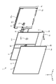
- the display device 1 includes a display panel 2, an enclosure EC (FIG. 2), a back chassis 3, an actuator 4, a woofer 5, and a rear cover 6.
- the actuator 4 includes a pair of actuators 4L and an actuator 4R.
- the actuator 4L is located on the left side (X-axis negative direction side), and the actuator 4R is located on the right side (X-axis positive direction side).
- the enclosure EC is shown in a state where it is provided in the back chassis 3.
- the front and back surfaces of the display panel 2 are referred to as front surface 2a and back surface 2b and are shown.
- the front surface and the back surface of the back chassis 3 are referred to as front surface 3a and back surface 3b and are shown.
- the inner side surface and the outer side surface of the rear cover 6 are referred to as an inner side surface 6a and an outer side surface 6b and are shown.
- the display panel 2 has a form (thickness, flexibility, etc.) that allows vibration so that sound waves can be generated, propagated, and the like.
- An example of such a display panel 2 is an OLED (Organic Light Emitting Diode) cell.
- the outer frame of the display panel 2 is referred to as a bezel B and is illustrated.
- the bezel B is not provided with other elements such as the woofer 5, and the bezel B is designed to be considerably thinner than the other parts of the display panel 2.
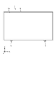
- FIG. 3 is a front view showing an example of a schematic configuration of a display device.
- the front surface 2a of the display panel 2 mainly constitutes the appearance of the display device 1 when viewed from the front.
- the bezel B of the display panel 2 looks quite thin.
- the enclosure EC will be described with reference to FIGS. 1 and 2 (particularly FIG. 2).
- the enclosure EC is a partition member that partitions the display panel 2 so that a plurality of independent vibration regions are formed on the display panel 2.
- the enclosure EC fixes the boundary portion between the plurality of vibration regions on the back surface 2b of the display panel 2 to the back chassis 3.
- the enclosure EC is, for example, an adhesive member.
- An example of an adhesive region is a double-sided tape having cushioning properties (elasticity).
- the enclosure EC may have a thickness (length in the Z-axis direction) of about several millimeters or less.
- the enclosure EC is a double-sided tape in which one side is in contact with the back surface 2b of the display panel 2 and the other side is in contact with the front surface 3a of the back chassis 3.
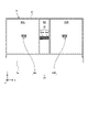
- FIG. 4 is a rear view showing an example of a schematic configuration of a display panel including an enclosure.
- the enclosure EC is shown by hatching.
- the enclosure EC is provided on the back surface 2b of the display panel 2 so that the vibration region R1L, the vibration region R1R, and the vibration region R2 are formed on the display panel 2.
- the enclosure EC is provided so as to surround each of the vibration region R1L, the vibration region R1R, and the vibration region R2.
- a part of the enclosure EC is located in the boundary region between adjacent vibration regions.
- the vibration region R1L and the vibration region R1R are the first vibration regions (a pair of first vibration regions) vibrated by the actuator 4L and the actuator 4R.
- the vibration region R2 is a second vibration region that is vibrated by the woofer 5.
- the back chassis 3 will be described with reference to FIGS. 1 and 2 again.
- the back chassis 3 is provided behind the display panel 2.
- the back chassis 3 supports the display panel 2 from behind the display panel 2.
- An example of the material of the back chassis 3 is a metal such as aluminum.
- the back chassis 3 has a plate shape having an area similar to that of the display panel 2 except for the pair of chassis stands S provided at the lower part. As a result, the display panel 2 is steadily supported throughout.
- FIG. 5 is a front view showing an example of a schematic configuration of a back chassis including an enclosure.
- the reference numerals thereof are shown at the positions corresponding to the vibration region R1L, the vibration region R1R and the vibration region R2 of the display panel 2 described above.
- the enclosure EC is provided on the front surface 3a of the back chassis 3 so that the vibration region R1L, the vibration region R1R, and the vibration region R2 are formed on the display panel 2.
- FIG. 6 is a partial rear view showing an example of the schematic configuration of the back chassis.
- the back chassis 3 includes an opening 34 and an opening 35.
- the opening 34 and the opening 35 expose a part of the back surface 2b of the display panel 2.
- the opening 34 is provided corresponding to the actuator 4. Since the actuator 4 includes the actuator 4L and the actuator 4R as described above, the opening 34 includes the opening 34L corresponding to the actuator 4L and the opening 34R corresponding to the actuator 4R.
- the opening 35 is provided corresponding to the woofer 5.
- the opening 35 includes a plurality of holes 35a.
- the hole 35a is provided so as to penetrate the back chassis 3 by, for example, punching.
- the actuator 4 and the woofer 5 will be described with reference to FIGS. 1 and 2 again.
- the actuator 4 and the woofer 5 are used to generate sound waves.
- the woofer 5 is configured to generate a sound wave having a frequency (for example, a frequency in the mid-low range) lower than the vibration frequency of the actuator 4 (for example, a frequency in the mid-high range).
- the woofer 5 is also referred to as a subwoofer or the like.
- the actuator 4 is provided so as to come into contact with the back surface 2b of the display panel 2.
- the actuator 4 is provided so that at least a part thereof is located in the opening 34 of the back chassis 3.
- the woofer 5 is provided so as to generate sound waves from behind the display panel 2 toward the back surface 2b of the display panel 2.
- the woofer 5 is provided so as to face the back surface 2b of the display panel 2 via the opening 35 of the back chassis 3.
- FIG. 7 is a partial rear view showing an example of a schematic configuration of a back chassis provided with an actuator and a woofer.
- the woofer 5 is located in the center of the display panel 2 in the lateral direction.
- the actuator 4L and the actuator 4R are located on opposite sides of the center of the display panel 2 (with the woofer 5 in between).
- the actuator 4L is located on the left side of the center of the display panel 2.
- the actuator 4R is located on the right side of the center of the display panel 2.
- the woofer 5 is located between the actuator 4R and the actuator 4L.
- the actuator 4L, the actuator 4R and the woofer 5 are located slightly above the center of the display panel 2 (Y-axis positive direction side). However, in the vertical direction, the actuator 4L, the actuator 4R, and the woofer 5 may be located at the center of the display panel 2 or may be located below the center.
- the actuator 4L includes a vibrating portion 41L and a housing 42L.
- the vibrating unit 41L comes into contact with the back surface 2b of the display panel 2 and vibrates the vibration region R1L of the display panel 2.
- the housing 42L is attached to the back chassis 3 so that at least a part of the vibrating portion 41L is located in the opening 34L of the back chassis 3. Installation is done by screwing or the like.
- the actuator 4L provided in this way can vibrate the vibration region R1L of the display panel 2.
- the actuator 4R includes a vibrating portion 41R and a housing 42R.
- the vibrating unit 41R contacts the back surface 2b of the vibrating region R1R of the display panel 2 and vibrates the vibrating region R1R of the display panel 2.
- the housing 42R is attached to the back chassis 3 so that at least a part of the vibrating portion 41R is located in the opening 34R of the back chassis 3.
- the actuator 4R provided in this way can vibrate the vibration region R1R of the display panel 2.
- the woofer 5 includes a speaker unit 51 and a housing 52.
- the speaker unit 51 includes a diaphragm that vibrates so as to generate sound waves in a predetermined direction.
- the housing 52 is attached to the back chassis 3 so that the diaphragm of the speaker unit 51 generates sound waves toward the back surface 2b of the vibration region R2 of the display panel 2 through the opening 35 of the back chassis 3.
- the diaphragm of the speaker unit 51 of the woofer 5 is separated from the back surface 2b of the display panel 2.
- the separation distance may correspond to the depth (length in the Z-axis direction) of the hole 35a of the opening 35.
- the sound wave generated by the woofer 5 propagates air to the back surface 2b of the display panel 2 through the opening 35.
- the vibration region R2 of the display panel 2 can be vibrated by the woofer 5 provided in this way.
- FIG. 8 is a partially enlarged view showing an example of a schematic configuration of a woofer attached to a back chassis.
- the housing 52 of the woofer 5 has a duct 52a.
- the duct 52a guides a part of the sound waves generated by the woofer 5 (due to the vibration of the diaphragm of the speaker unit 51) in a direction other than the direction toward the back surface 2b of the display panel 2 (Z-axis positive direction).
- the duct 52a is a plurality of ducts having an opening at the upper part of the housing 52 so as to guide a part of the sound waves upward (Y-axis positive direction) and provided at both ends of the housing 52. ..
- the duct 52a has, for example, a pipe shape extending in the vertical direction.
- a structure provided with such a duct 52a is also called a bass reflex type speaker structure or the like.
- various other elements may be provided on the back surface 3b of the back chassis 3.
- An example of another element is a control circuit board of the display panel 2.
- the rear cover 6 will be described with reference to FIGS. 1 and 2 again.
- the rear cover 6 covers the elements provided on the back surface 3b of the back chassis 3 from behind so as to be accommodated between the back chassis 3 and the rear cover 6.
- the rear cover 6 covers at least the woofer 5 from behind and covers the actuator 4 and the woofer 5 in the illustrated example.
- the rear cover 6 may have a box shape having an opening on the back chassis 3 side at least.
- the upper side wall portion of the four side wall portions constituting the box shape is referred to as a side wall portion 61 and is illustrated.
- a slit 61a is formed in the side wall portion 61.
- the slit 61a is an aspect of the duct 52a of the woofer 5 and an opening for outputting a part of the sound wave guided by the space between the woofer 5 and the back chassis 3 to the outside of the rear cover 6.
- the space between the woofer 5 and the back chassis 3 is formed, for example, by providing a member M (FIG. 9) described later so as to close the space between the woofer 5 and the back chassis 3.
- FIG. 9 is a partial cross-sectional view schematically showing an example of the path of the sound wave generated by the woofer.
- the traveling direction of the sound wave is schematically indicated by a white arrow or the like.
- the display panel 2 and the back chassis 3 are separated from each other by, for example, about 0.9 mm via an enclosure EC (not shown in FIG. 9), whereby a vibration space for the display panel 2 is secured.
- the sound wave generated by the woofer 5 (due to the vibration of the diaphragm of the speaker unit 51) mainly passes through the hole 35a of the opening 35 and reaches the back surface 2b of the display panel 2.
- the display panel 2 (vibration region R2) vibrates, and substantially the same sound wave as the sound wave generated by the woofer 5 is generated and heads toward the front of the display panel 2.
- the sound wave generated by the actuator 4 also goes to the front of the display panel 2. Therefore, the phase of the sound wave generated by the actuator 4 and the phase of the sound wave generated by the woofer 5 are likely to be aligned at the position in front of the display panel 2.
- a part of the sound wave generated by the woofer 5 passes through the duct 52a and the slit 61a described above and is output to the outside of the rear cover 6. Further, in the example shown in FIG. 9, a member M (for example, a cushioning member) is provided between the woofer 5 and the back chassis 3, thereby forming a space between the woofer 5 and the back chassis 3. .. A part of the sound wave generated by the woofer 5 is output even through this space. A part of the output sound wave goes around the display panel 2 and heads forward. This also causes the sound wave to move toward the front of the display panel 2. By providing another path for the sound wave generated by the woofer 5 in this way, it becomes easy to secure the sound pressure, the reproduction band, and the like.
- FIG. 10 is a rear view showing an example of a schematic configuration of a display device. As shown in FIG. 10, the outer surface 6b of the rear cover 6 mainly constitutes the appearance of the display device 1 when viewed from the rear.
- the display device 1 includes a display panel 2 (for example, an OLED cell), an actuator 4 provided so as to contact the back surface 2b of the display panel 2, and a display panel.
- a woofer 5 provided so as to generate a sound wave from behind the display panel 2 toward the back surface 2b of the display panel 2 is provided.
- the sound wave generated by the woofer 5 vibrates the display panel 2.
- the phase of the sound wave generated by the actuator 4 and the phase of the sound wave generated by the woofer 5 can be easily aligned. Therefore, deterioration of sound quality due to the phase shift of both sound waves can be suppressed.
- the display device 1 includes a back chassis 3 that supports the display panel 2 from behind the display panel 2, and the back chassis 3 displays. It has an opening 35 (for example, a plurality of holes 35a) that exposes a part of the back surface 2b of the panel 2, and the woofer 5 faces the back surface 2b of the display panel 2 via the opening 35 of the back chassis 3. It may be provided in. As a result, the sound wave generated by the woofer 5 can be air-propagated to the back surface 2b of the display panel 2 through the opening 35.
- the woofer 5 has a diaphragm (inside the speaker unit 51) that vibrates so as to generate the sound wave in a predetermined direction, and a diaphragm. It may include a housing 52 having a duct 52a that guides a part of the sound waves generated by the display panel 2 in a direction other than the direction toward the back surface 2b of the display panel 2 (Z-axis positive direction).
- the display device 1 includes a rear cover that covers at least the woofer 5 from behind, and the rear cover 6 may have an opening (slit 61a) that outputs a part of the sound waves guided by the duct 52a to the outside of the rear cover 6.
- the sound wave generated by the woofer 5 can be output forward even in a path different from that of the opening 35. As a result, for example, it becomes easier to secure the sound pressure, the reproduction band, and the like as compared with the case of using only the sound wave generated by the vibration of the display panel 2 by the woofer 5.
- the display device 1 is an enclosure EC (partition member) that partitions the display panel 2 so that a plurality of independent vibration regions are formed on the display panel 2.
- the plurality of vibration regions include a first vibration region (vibration region R1L and vibration region R1R) vibrated by the actuator 4, and a second vibration region (vibration region R2) vibrated by the sound wave generated by the woofer 5.
- the enclosure EC may be an adhesive member that fixes a boundary portion between a plurality of vibration regions on the back surface 2b of the display panel 2 to the back chassis 3.
- the actuator 4 is a pair of actuators 4L and 4R provided on both sides of the central portion of the display panel 2, and the first vibration region is formed by the corresponding actuators of the pair of actuators 4L and 4R, respectively.
- a pair of vibrating first vibration regions (vibration region R1L and vibration region R1L) may be included.
- the woofer 5 may be located between the pair of actuators 4L and 4R.
- the woofer 5 may generate a sound wave having a frequency lower than the vibration frequency of the actuator 4. Thereby, for example, it is possible to generate a sound wave having a wider range as a whole than when only the actuator 4 is used.
- the panel 21 of the display panel 2 is an OLED cell
- any display panel that can be vibrated by the actuator 4 and can be vibrated by the sound wave generated by the woofer 5 may be used.
- the opening 35 has a plurality of holes 35a
- the number of holes may be one, and the shape of the holes and the like are not limited to the illustrated examples.
- the actuator 4 a pair of actuators 4L and actuators 4R arranged on both sides of the woofer 5 will be described as an example.
- the number of actuators may be one or three or more.
- an example in which one woofer 5 is arranged in the center of the display panel 2 has been described.
- two or more woofers may be provided.
- a pair of woofers for Lch and Rch may be provided on both sides of the central portion of the display panel 2.
- the enclosure EC may also be provided to partition the corresponding vibration regions. Thereby, for example, it is possible to provide a stereo feeling of sound in a wider range. This merit becomes apparent especially when many vibration regions having a large screen size of the display panel 2 can be formed.
- the duct 52a of the housing 52 of the woofer 5 may be provided to guide some sound waves in all directions except the front.
- the number of ducts is also not limited to the examples shown.
- a slit may be formed in a portion other than the side wall portion 61 of the rear cover 6.
- the present technology can also have the following configurations.
- Display panel and An actuator provided so as to come into contact with the back surface of the display panel, A woofer provided to generate sound waves from the back of the display panel toward the back of the display panel, and To prepare Display device.
- a back chassis that supports the display panel from behind the display panel is provided.
- the back chassis has an opening that exposes a portion of the back surface of the display panel.
- the woofer is provided so as to face the back surface of the display panel via the opening of the back chassis.
- the opening comprises a plurality of holes.
- the woofer is A diaphragm that vibrates to generate the sound wave in a predetermined direction, A housing having a duct that guides a part of the sound waves generated by the diaphragm in a direction other than the direction toward the back surface of the display panel. including, The display device according to (2) or (3). (5) With a rear cover that covers at least the woofer from behind The rear cover has an opening that outputs a part of the sound wave guided by the duct to the outside of the rear cover. The display device according to (4). (6) A partition member for partitioning the display panel is provided so that a plurality of independent vibration regions are formed on the display panel.
- the plurality of vibration regions are The first vibration region vibrated by the actuator and A second vibration region vibrated by the sound wave generated by the woofer, and including, The display device according to any one of (1) to (5).
- the partition member is an adhesive member that fixes a boundary portion between the plurality of vibration regions on the back surface of the display panel to a back chassis that supports the display panel from the back surface.
- the actuators are a pair of actuators provided on both sides of a central portion of the display panel.
- the first vibration region includes a pair of first vibration regions, each vibrating by the corresponding actuator of the pair of actuators.
- the woofer is located between the pair of actuators.
- the woofer generates sound waves at a frequency lower than the vibration frequency of the actuator.
- the display panel is an OLED cell.
Landscapes
- Physics & Mathematics (AREA)
- Engineering & Computer Science (AREA)
- Acoustics & Sound (AREA)
- Signal Processing (AREA)
- Health & Medical Sciences (AREA)
- Otolaryngology (AREA)
- Details Of Audible-Bandwidth Transducers (AREA)
- Devices For Indicating Variable Information By Combining Individual Elements (AREA)
Abstract
Description
1.はじめに
2.実施形態
3.効果
OLEDセルのような表示パネルを備える表示装置では、音波を発生するためにアクチュエータ及びウーファが用いられることがある。例えば、アクチュエータが表示パネルを振動させることにより、中高域の音波が発生する。ウーファの振動板が振動することにより、中低域の音波(空気の粗密波)が発生する。
実施形態に係る表示装置について、図1~図10を参照して説明する。図において、XYZ座標系が示される。X軸方向及びY軸方向は、表示装置の横方向及び縦方向(幅方向及び高さ方向)に対応する。Z軸向は、表示装置の前後方向(厚さ方向)に対応する。Z軸正方向は、表示装置の前方方向に対応する。
以上説明した表示装置1は、例えば次のように説明される。図1及び図2等を参照して説明したように、表示装置1は、表示パネル2(例えばOLEDセル)と、表示パネル2の背面2bに接触するように設けられたアクチュエータ4と、表示パネル2の背後から表示パネル2の背面2bに向かって音波を発生するように設けられたウーファ5と、を備える。
(1)
表示パネルと、
前記表示パネルの背面に接触するように設けられたアクチュエータと、
前記表示パネルの背後から前記表示パネルの背面に向かって音波を発生するように設けられたウーファと、
を備える、
表示装置。
(2)
前記表示パネルの背後から前記表示パネルを支持するバックシャーシを備え、
前記バックシャーシは、前記表示パネルの背面の一部を露出させる開口部を有し、
前記ウーファは、前記バックシャーシの前記開口部を介して、前記表示パネルの前記背面と対向するように設けられる、
(1)に記載の表示装置。
(3)
前記開口部は、複数の孔を含む、
(2)に記載の表示装置。
(4)
前記ウーファは、
所定の方向に前記音波を発生するように振動する振動板と、
前記振動板によって発生した前記音波の一部の音波を前記表示パネルの背面に向かう方向以外の方向に導くダクトを有する筐体と、
を含む、
(2)又は(3)に記載の表示装置。
(5)
少なくとも前記ウーファを背後から覆うリアカバーを備え、
前記リアカバーは、前記ダクトによって導かれた前記一部の音波を前記リアカバーの外部に出力する開口部を有する、
(4)に記載の表示装置。
(6)
独立した複数の振動領域が前記表示パネルに形成されるように前記表示パネルを仕切る仕切部材を備え、
前記複数の振動領域は、
前記アクチュエータによって振動する第1の振動領域と、
前記ウーファによって発生した音波によって振動する第2の振動領域と、
を含む、
(1)~(5)のいずれかに記載の表示装置。
(7)
前記仕切部材は、前記表示パネルの背面における前記複数の振動領域どうしの境界部分を、前記表示パネルを背面から支持するバックシャーシに固定する接着部材である、
(6)に記載の表示装置。
(8)
前記アクチュエータは、前記表示パネルの中央部分の両側部分に設けられた一対のアクチュエータであり、
前記第1の振動領域は、各々が前記一対のアクチュエータのうちの対応するアクチュエータによって振動する一対の第1の振動領域を含む、
(6)又は(7)に記載の表示装置。
(9)
前記ウーファは、前記一対のアクチュエータの間に位置している、
(8)に記載の表示装置。
(10)
前記ウーファは、少なくとも前記アクチュエータの振動周波数よりも低い周波数の音波を発生する、
(1)~(9)のいずれかに記載の表示装置。
(11)
前記表示パネルは、OLEDセルである、
(1)~(10)のいずれかに記載の表示装置。
2 表示パネル
3 バックシャーシ
4 アクチュエータ
5 ウーファ
6 リアカバー
34 開口部
35 開口部
35a 孔
52 筐体
52a ダクト
61a スリット(開口部)
EC エンクロージャ(仕切部材)
M 部材
R1L 振動領域
R1R 振動領域
R2 振動領域
Claims (11)
- 表示パネルと、
前記表示パネルの背面に接触するように設けられたアクチュエータと、
前記表示パネルの背後から前記表示パネルの背面に向かって音波を発生するように設けられたウーファと、
を備える、
表示装置。 - 前記表示パネルの背後から前記表示パネルを支持するバックシャーシを備え、
前記バックシャーシは、前記表示パネルの背面の一部を露出させる開口部を有し、
前記ウーファは、前記バックシャーシの前記開口部を介して、前記表示パネルの前記背面と対向するように設けられる、
請求項1に記載の表示装置。 - 前記開口部は、複数の孔を含む、
請求項2に記載の表示装置。 - 前記ウーファは、
所定の方向に前記音波を発生するように振動する振動板と、
前記振動板によって発生した前記音波の一部の音波を前記表示パネルの背面に向かう方向以外の方向に導くダクトを有する筐体と、
を含む、
請求項2に記載の表示装置。 - 少なくとも前記ウーファを背後から覆うリアカバーを備え、
前記リアカバーは、前記ダクトによって導かれた前記一部の音波を前記リアカバーの外部に出力する開口部を有する、
請求項4に記載の表示装置。 - 独立した複数の振動領域が前記表示パネルに形成されるように前記表示パネルを仕切る仕切部材を備え、
前記複数の振動領域は、
前記アクチュエータによって振動する第1の振動領域と、
前記ウーファによって発生した音波によって振動する第2の振動領域と、
を含む、
請求項1に記載の表示装置。 - 前記仕切部材は、前記表示パネルの背面における前記複数の振動領域どうしの境界部分を、前記表示パネルを背面から支持するバックシャーシに固定する接着部材である、
請求項6に記載の表示装置。 - 前記アクチュエータは、前記表示パネルの中央部分の両側部分に設けられた一対のアクチュエータであり、
前記第1の振動領域は、各々が前記一対のアクチュエータのうちの対応するアクチュエータによって振動する一対の第1の振動領域を含む、
請求項6に記載の表示装置。 - 前記ウーファは、前記一対のアクチュエータの間に位置している、
請求項8に記載の表示装置。 - 前記ウーファは、少なくとも前記アクチュエータの振動周波数よりも低い周波数の音波を発生する、
請求項1に記載の表示装置。 - 前記表示パネルは、OLEDセルである、
請求項1に記載の表示装置。
Priority Applications (4)
| Application Number | Priority Date | Filing Date | Title |
|---|---|---|---|
| US18/267,228 US20240015426A1 (en) | 2020-12-21 | 2021-12-07 | Display Device |
| CN202180080537.1A CN116530096A (zh) | 2020-12-21 | 2021-12-07 | 显示装置 |
| JP2022572084A JP7764864B2 (ja) | 2020-12-21 | 2021-12-07 | 表示装置 |
| EP21910277.9A EP4266696A4 (en) | 2020-12-21 | 2021-12-07 | Display apparatus |
Applications Claiming Priority (2)
| Application Number | Priority Date | Filing Date | Title |
|---|---|---|---|
| JP2020210931 | 2020-12-21 | ||
| JP2020-210931 | 2020-12-21 |
Publications (1)
| Publication Number | Publication Date |
|---|---|
| WO2022138128A1 true WO2022138128A1 (ja) | 2022-06-30 |
Family
ID=82159628
Family Applications (1)
| Application Number | Title | Priority Date | Filing Date |
|---|---|---|---|
| PCT/JP2021/044864 Ceased WO2022138128A1 (ja) | 2020-12-21 | 2021-12-07 | 表示装置 |
Country Status (5)
| Country | Link |
|---|---|
| US (1) | US20240015426A1 (ja) |
| EP (1) | EP4266696A4 (ja) |
| JP (1) | JP7764864B2 (ja) |
| CN (1) | CN116530096A (ja) |
| WO (1) | WO2022138128A1 (ja) |
Cited By (1)
| Publication number | Priority date | Publication date | Assignee | Title |
|---|---|---|---|---|
| JP2024007538A (ja) * | 2022-07-05 | 2024-01-18 | エルジー ディスプレイ カンパニー リミテッド | 装置 |
Families Citing this family (4)
| Publication number | Priority date | Publication date | Assignee | Title |
|---|---|---|---|---|
| USD1058526S1 (en) * | 2021-01-08 | 2025-01-21 | Sony Group Corporation | Television receiver |
| EP4401422A4 (en) * | 2021-11-30 | 2025-01-08 | Samsung Electronics Co., Ltd. | DISPLAY DEVICE FOR FRONT AUDIO RADIATION |
| KR20230100821A (ko) * | 2021-12-28 | 2023-07-06 | 삼성디스플레이 주식회사 | 표시 장치 |
| US12538076B2 (en) * | 2022-09-16 | 2026-01-27 | Denso Ten Limited | Sound device and control method |
Citations (3)
| Publication number | Priority date | Publication date | Assignee | Title |
|---|---|---|---|---|
| JP2004187271A (ja) * | 2002-11-20 | 2004-07-02 | Sharp Corp | 表示装置 |
| WO2018123288A1 (ja) | 2016-12-27 | 2018-07-05 | ソニー株式会社 | 表示装置 |
| US20190191240A1 (en) * | 2017-12-20 | 2019-06-20 | Lg Display Co., Ltd. | Display apparatus |
Family Cites Families (6)
| Publication number | Priority date | Publication date | Assignee | Title |
|---|---|---|---|---|
| JPH10262293A (ja) * | 1997-03-19 | 1998-09-29 | Sony Corp | 機器の音響装置 |
| KR101629822B1 (ko) * | 2009-07-27 | 2016-06-13 | 삼성전자주식회사 | 저음 증폭용 엔클로저, 상기 엔클로저를 구비한 우퍼, 및 상기 우퍼를 구비한 전자기기 |
| US9553960B1 (en) * | 2015-09-04 | 2017-01-24 | Intel Corporation | Loudspeaker with laminate panel for mobile computing platforms |
| KR101817103B1 (ko) * | 2016-06-30 | 2018-01-10 | 엘지디스플레이 주식회사 | 패널 진동형 음향 발생 표시 장치 |
| CN110913319B (zh) * | 2018-09-18 | 2021-10-01 | 乐金显示有限公司 | 显示设备 |
| CN111383563B (zh) * | 2018-12-31 | 2022-07-08 | 乐金显示有限公司 | 显示装置 |
-
2021
- 2021-12-07 CN CN202180080537.1A patent/CN116530096A/zh active Pending
- 2021-12-07 JP JP2022572084A patent/JP7764864B2/ja active Active
- 2021-12-07 WO PCT/JP2021/044864 patent/WO2022138128A1/ja not_active Ceased
- 2021-12-07 EP EP21910277.9A patent/EP4266696A4/en active Pending
- 2021-12-07 US US18/267,228 patent/US20240015426A1/en not_active Abandoned
Patent Citations (3)
| Publication number | Priority date | Publication date | Assignee | Title |
|---|---|---|---|---|
| JP2004187271A (ja) * | 2002-11-20 | 2004-07-02 | Sharp Corp | 表示装置 |
| WO2018123288A1 (ja) | 2016-12-27 | 2018-07-05 | ソニー株式会社 | 表示装置 |
| US20190191240A1 (en) * | 2017-12-20 | 2019-06-20 | Lg Display Co., Ltd. | Display apparatus |
Non-Patent Citations (1)
| Title |
|---|
| See also references of EP4266696A4 |
Cited By (2)
| Publication number | Priority date | Publication date | Assignee | Title |
|---|---|---|---|---|
| JP2024007538A (ja) * | 2022-07-05 | 2024-01-18 | エルジー ディスプレイ カンパニー リミテッド | 装置 |
| JP7673126B2 (ja) | 2022-07-05 | 2025-05-08 | エルジー ディスプレイ カンパニー リミテッド | 装置 |
Also Published As
| Publication number | Publication date |
|---|---|
| US20240015426A1 (en) | 2024-01-11 |
| JPWO2022138128A1 (ja) | 2022-06-30 |
| CN116530096A (zh) | 2023-08-01 |
| EP4266696A4 (en) | 2024-05-22 |
| JP7764864B2 (ja) | 2025-11-06 |
| EP4266696A1 (en) | 2023-10-25 |
Similar Documents
| Publication | Publication Date | Title |
|---|---|---|
| JP7764864B2 (ja) | 表示装置 | |
| EP3334182B1 (en) | Directional speaker and display apparatus having the same | |
| KR102874535B1 (ko) | 디스플레이 장치 | |
| US20140193005A1 (en) | Audio Speaker System with Semi-Shared Passive Radiators | |
| JP7552590B2 (ja) | スピーカ装置、スピーカ、及び構造体 | |
| EP3684077A1 (en) | Diffuser | |
| CN113994712B (zh) | 显示设备 | |
| US10477317B2 (en) | Speaker structure | |
| US20220329932A1 (en) | Loudspeaker | |
| JP5166973B2 (ja) | スピーカ装置及びその駆動方法 | |
| JPWO2020141581A1 (ja) | 表示装置及びスピーカー | |
| US10939196B2 (en) | Loudspeaker and electronic apparatus including the same | |
| EP4304195A1 (en) | Speaker device | |
| JP2006237826A (ja) | 平面表示機器用スピーカ装置及び平面表示装置 | |
| JP7142198B2 (ja) | スピーカ装置 | |
| JP7709132B2 (ja) | スピーカユニットおよび言語学習支援装置 | |
| KR20070006808A (ko) | 분산형 음향 캐비넷 | |
| JPWO2020137177A1 (ja) | 表示装置 | |
| JP7775697B2 (ja) | 放音装置及び電子楽器 | |
| CN109525925B (zh) | 扬声器装置以及具备扬声器装置的设备 | |
| JP3816016B2 (ja) | バスレフ型スピーカー装置 | |
| JP2018129685A (ja) | 表示装置及びテレビジョン受像機 | |
| TW202134748A (zh) | 顯示器及其出音裝置 | |
| WO2022186307A1 (ja) | 電子楽器 | |
| WO2025022701A1 (ja) | スピーカ装置 |
Legal Events
| Date | Code | Title | Description |
|---|---|---|---|
| 121 | Ep: the epo has been informed by wipo that ep was designated in this application |
Ref document number: 21910277 Country of ref document: EP Kind code of ref document: A1 |
|
| ENP | Entry into the national phase |
Ref document number: 2022572084 Country of ref document: JP Kind code of ref document: A |
|
| WWE | Wipo information: entry into national phase |
Ref document number: 202180080537.1 Country of ref document: CN |
|
| WWE | Wipo information: entry into national phase |
Ref document number: 18267228 Country of ref document: US |
|
| WWE | Wipo information: entry into national phase |
Ref document number: 2021910277 Country of ref document: EP |
|
| NENP | Non-entry into the national phase |
Ref country code: DE |
|
| ENP | Entry into the national phase |
Ref document number: 2021910277 Country of ref document: EP Effective date: 20230721 |