WO2022145013A1 - ギヤスカイビング加工法 - Google Patents
ギヤスカイビング加工法 Download PDFInfo
- Publication number
- WO2022145013A1 WO2022145013A1 PCT/JP2020/049239 JP2020049239W WO2022145013A1 WO 2022145013 A1 WO2022145013 A1 WO 2022145013A1 JP 2020049239 W JP2020049239 W JP 2020049239W WO 2022145013 A1 WO2022145013 A1 WO 2022145013A1
- Authority
- WO
- WIPO (PCT)
- Prior art keywords
- skiving
- work
- tooth
- cutters
- cutter
- Prior art date
- Legal status (The legal status is an assumption and is not a legal conclusion. Google has not performed a legal analysis and makes no representation as to the accuracy of the status listed.)
- Ceased
Links
Images


Classifications
-
- B—PERFORMING OPERATIONS; TRANSPORTING
- B23—MACHINE TOOLS; METAL-WORKING NOT OTHERWISE PROVIDED FOR
- B23F—MAKING GEARS OR TOOTHED RACKS
- B23F5/00—Making straight gear teeth involving moving a tool relatively to a workpiece with a rolling-off or an enveloping motion with respect to the gear teeth to be made
- B23F5/12—Making straight gear teeth involving moving a tool relatively to a workpiece with a rolling-off or an enveloping motion with respect to the gear teeth to be made by planing or slotting
- B23F5/16—Making straight gear teeth involving moving a tool relatively to a workpiece with a rolling-off or an enveloping motion with respect to the gear teeth to be made by planing or slotting the tool having a shape similar to that of a spur wheel or part thereof
- B23F5/163—Making straight gear teeth involving moving a tool relatively to a workpiece with a rolling-off or an enveloping motion with respect to the gear teeth to be made by planing or slotting the tool having a shape similar to that of a spur wheel or part thereof the tool and workpiece being in crossed axis arrangement, e.g. skiving, i.e. "Waelzschaelen"
-
- B—PERFORMING OPERATIONS; TRANSPORTING
- B23—MACHINE TOOLS; METAL-WORKING NOT OTHERWISE PROVIDED FOR
- B23F—MAKING GEARS OR TOOTHED RACKS
- B23F5/00—Making straight gear teeth involving moving a tool relatively to a workpiece with a rolling-off or an enveloping motion with respect to the gear teeth to be made
- B23F5/12—Making straight gear teeth involving moving a tool relatively to a workpiece with a rolling-off or an enveloping motion with respect to the gear teeth to be made by planing or slotting
- B23F5/16—Making straight gear teeth involving moving a tool relatively to a workpiece with a rolling-off or an enveloping motion with respect to the gear teeth to be made by planing or slotting the tool having a shape similar to that of a spur wheel or part thereof
- B23F5/166—Making straight gear teeth involving moving a tool relatively to a workpiece with a rolling-off or an enveloping motion with respect to the gear teeth to be made by planing or slotting the tool having a shape similar to that of a spur wheel or part thereof with plural tools
Definitions
- the present invention is a gear skiving processing method in which a skiving cutter (gear-type tool) is used to perform gear cutting on one of the outer peripheral surface and the inner peripheral surface of a cylindrical workpiece (gear). Regarding.
- the gear skiving processing method is known as a gear cutting method for internal gears and external gears.
- the tool is rotated in the axial direction of the work while the rotation shaft of the work (work gear) and the rotation shaft of the tool are given an axial angle and both are rotated at a rotation ratio according to the number of teeth ratio. Process by sending to.
- FIG. 4A is an explanatory diagram showing an example of a machining state of a workpiece for an internal gear by a skiving cutter in gear skiving machining.
- the skiving cutter 1 is arranged so that its rotation axis 1a has a predetermined intersection angle (axis intersection angle) with the rotation axis 3a of the work 3 (internal gear to be machined).
- the skiving cutter 1 is positioned at a predetermined machining position in the circumferential direction on the work surface 31 (circular inner peripheral surface) of the work 3.
- the work 3 and the skiving cutter 1 are rotated synchronously in the same direction. In this state, the skiving cutter 1 is fed along the work surface 31 of the work 3 in the direction of the rotation axis 3a of the work.
- the internal teeth 32 are formed on the work surface 31 of the work 3 by the cutting blade 1b of the skiving cutter 1.
- the shape and twist angle of the cutting edge of the skiving cutter 1, the axial crossing angle between the skiving cutter 1 and the work 3, and each of the skiving cutter 1 and the work 3. Processing conditions such as the rotation speed of the skiving cutter 1, the feed speed of the skiving cutter 1, and the depth of cut are appropriately set.
- FIG. 4B is a schematic diagram showing the skiving cutter 1 and the work 3 shown in FIG. 4A in a simplified manner. Similarly, in each of the figures (FIGS. 1 to 3) described below, the skiving cutter and the work are shown in a simplified manner.
- the same skiving tool is used to perform gear cutting twice on the workpiece to finish the right tooth surface and the left tooth surface to be created. Processing is performed in a separate process.
- a tooth profile in which the tooth surface shape changes in the tooth muscle direction by performing gear cutting while moving the skiving cutter along the axial direction and the circumferential direction of the work material. It makes it possible to create a tooth profile whose tooth length changes in the direction of the tooth muscle.
- an object of the present invention is gear skiving capable of efficiently performing gear cutting of a gear having a tooth profile that changes along the tooth trace direction, a tooth profile that has different tooth surfaces on the left and right, and the like. It is to propose a processing method.
- the present invention relates to a gear skiving processing method in which gear cutting is performed on one of the outer peripheral surface and the inner peripheral surface of a cylindrical workpiece.
- the first skiving cutter is positioned at the first machining position in the circumferential direction on the work surface of the work so as to have a predetermined depth of cut.
- the second skiving cutter is positioned at the second machining position on the work surface, which is separated from the first machining position by a predetermined angle in the circumferential direction, so as to have a predetermined depth of cut.
- the first skiving cutter is arranged with respect to the work so as to have the first axis crossing angle
- the second skiving cutter is arranged with respect to the work so as to have the second axis crossing angle.
- the first and second skiving cutters While synchronously rotating the work and the first and second skiving cutters, the first and second skiving cutters are simultaneously sent in the direction of the rotation axis of the work to perform gear cutting of the work surface.
- gear cutting process one of the left tooth surface and the right tooth surface of the tooth created on the work surface is cut by the first skiving cutter, and the second skiving cutter is used.
- the left tooth surface and the right tooth surface are characterized by cutting the other tooth surface.
- the work is geared using two skiving cutters.
- the tooth cutting process is performed in one step, one of the left and right tooth surfaces of the tooth to be created is processed by the first skiving cutter, and the other is processed by the second skiving cutter.
- the tooth cutting process consisting of one process, it is possible to efficiently cut teeth having an asymmetric tooth surface on the left and right.
- the tooth cutting process can be performed in two steps.
- the cutting edge of the first skiving cutter is processed so as to have an acute rake angle with respect to one of the tooth surfaces on both sides of the tooth created on the work surface of the work.
- the processing conditions are set so that the cutting edge of the second skiving cutter has an acute rake angle with respect to the other tooth surface, and the other tooth surface is cut.
- the left and right tooth surfaces can be processed into different tooth profiles.
- the pressure angle can be changed from the middle of the tooth muscle direction.
- a three-dimensional tooth profile having a symmetrical tooth surface in which the pressure angle changes along the direction of the tooth muscle or a left-right asymmetric tooth surface can be obtained.
- a tapered tooth profile in which the tooth length changes along the tooth muscle direction can be obtained.
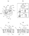
- (A) is an explanatory diagram showing an example of the machining state of the work by the first and second skiving cutters in the roughing process of the work for the internal gear, and (b) is an axial crossing angle, a rotation direction and a left tooth. It is explanatory drawing which shows the surface and the right tooth surface, (c) shows the arrangement relation of the 1st skiving cutter with respect to the work surface when viewed from the direction along the diameter line of the work which passes through the center of the 1st skiving cutter. It is explanatory drawing which shows, (d) is explanatory drawing which shows the arrangement relation of the 2nd skiving cutter with respect to the work surface when seen from the direction along the diameter line of the work which passes through the center of the 2nd skiving cutter.
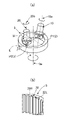
- (A) is an explanatory view showing an example of the processing state of the work by the first and second skiving cutters in the finishing processing process, and (b) is the right tooth surface and the left of the internal teeth formed on the work surface of the work. It is explanatory drawing which shows the tooth surface.
- (A) is an explanatory diagram showing an example of the machining state of the work by the first and second skiving cutters in the roughing process of the work for the internal gear, and (b) is the main machining conditions and the right tooth surface.
- FIG. 3D is an explanatory diagram showing the arrangement relationship of the second skiving cutter with respect to the work surface when viewed from the direction along the diameter line of the work passing through the center of the second skiving cutter.
- A is an explanatory diagram showing an example of a machining state of a work for an internal gear by a skiving cutter
- (b) is an explanatory diagram showing a simplified skiving cutter and a work.
- the work for the internal gear is obtained, for example, through a material forging process and a turning process.
- the work is subjected to a roughing step (first gear cutting step), and internal teeth (tooth grooves) are machined on the circular inner peripheral surface which is the work surface thereof.
- the work is subjected to a finishing process on the left tooth surface and the right tooth surface of the internal teeth in the finishing step (second gear cutting step) after undergoing a step such as heat treatment.
- the gear skiving process of the present invention is used in the roughing process and the finishing process.
- the first skiving cutter 10 is positioned at the first machining position P1 (1) in the circumferential direction on the work surface 31 of the work 3.
- the second skiving cutter 20 is positioned at the second machining position P2 (1) separated from the first machining position P1 on the work surface 31 by an angle of 180 ° in the circumferential direction. That is, the first and second skiving cutters 10 and 20 are arranged at opposite positions facing each other with the rotation shaft 3a of the work 3 interposed therebetween.
- first and second skiving cutters 10 and 20 cutters having the same configuration are used. Further, the rotation shafts 10a and 20a of the first and second skiving cutters 10 and 20 are tilted in the same direction by the same angle with respect to the rotation shaft 3a of the work 3. That is, assuming that the axis crossing angle (first axis crossing angle) between the first skiving cutter 10 and the work 3 is ⁇ , the axis crossing angle (second axis) between the second skiving cutter 20 and the work 3 (Cross angle) is also ⁇ . The rotation direction of the work 3, the first and second skiving cutters 10 and 20 is clockwise.
- the portion where the right tooth surface 32R of the internal tooth 32 is formed is mainly cut by the cutting edge portion of the cutting edge that hits the work surface 31 of the work 3 at an acute rake angle.
- the portion where the left tooth surface 32L of the internal tooth 32 is formed is mainly cut by the cutting edge portion of the cutting edge that hits the work surface 31 at the obtuse rake angle.
- the first and second skiving cutters 10 and 20 rotate from the work surface 31 with respect to the first and second machining positions P1 (1) and P2 (2) on the diameter line L in the work circumferential direction. It is located off the axis 3a in the direction.
- the first and second skiving cutters 10 and 20 are rotated synchronously in the same direction as the rotation direction of the work 3.
- the first and second skiving cutters 10 and 20 are positioned in the work diameter direction so as to have a predetermined depth of cut.
- the work surface 31 is cut at a predetermined speed in the direction along the rotation axis 3a of the work 3 with respect to the work surface 31 of the work 3 to create a tooth groove of the internal teeth 32.
- the first skiving cutter 10 mainly cuts the portion of the internal tooth 32 that becomes the right tooth surface 32R
- the second skiving cutter 20 mainly cuts the portion of the internal tooth 32 that becomes the left tooth surface 32L. ..
- the tooth surface finishing process which is the second tooth cutting process, will be described with reference to FIGS. 2 (a) and 2 (b).
- the tooth surface finishing step the right tooth surface 32R of each internal tooth 32 created on the machined surface 31 by the roughing step is mainly finished by using the first skiving cutter 10.
- the other left tooth surface 32L is mainly finished by using the second skiving cutter 20.
- the shaft crossing angle between the first skiving cutter 10 and the work 3 is set to ⁇
- the shaft crossing angle between the second skiving cutter 20 and the work is also set to the same ⁇ . ..
- the processing position of the first skiving cutter 10 is set from the first processing position P1 (1) on the diameter line L in the first gear cutting step to the right clock.
- the position is changed to the first processing position P1 (2), which is moved around by a minute angle ⁇ .
- the machining position of the second skiving cutter 20 is moved by the same angle ⁇ counterclockwise in the circumferential direction from the second machining position P2 (1) of the diameter line L in the first gear cutting step. Change to P2 (2).
- the amount of movement (angle) is very small, but it is exaggerated in the figure.
- FIG. 2B is an enlarged explanatory view showing the internal teeth 32 formed on the work surface 31 of the work 3.
- the finishing process of the right tooth surface 32R of the internal tooth 32 is mainly performed by the first skiving cutter 10.
- the finishing process of the left tooth surface 32L on the opposite side is mainly performed by the second skiving cutter 20.
- the feed rate, depth of cut, etc. of the first and second skiving cutters 10 and 20 can be controlled independently. Therefore, it is possible to process an internal tooth having an asymmetric tooth surface on the left and right.
- the axis crossing angles of the first and second skiving cutters 10 and 20 are changed during the processing, so that the pressure angles of the left and right tooth surfaces are changed from the middle of the tooth muscle direction. Can be changed. This makes it possible to process a three-dimensional tooth profile in which the pressure angles of the left and right tooth surfaces change symmetrically along the direction of the tooth muscle.
- the processing time can be shortened as compared with the case of using a single cutter. Further, it is possible to suppress the wear of the cutting edge of the cutters 10 and 20 and extend the life of the cutters 10 and 20.
- the work surface 31 of the work 3 is simultaneously processed by the first and second skiving cutters 10 and 20.
- Each step may be divided into two steps, that is, processing by the first skiving cutter 10 and processing by the second skiving cutter 20.
- FIG. 3 is an explanatory diagram showing gear cutting of the internal gear in the case of two steps.
- the first skiving cutter 10 in the roughing step, is positioned at the first machining position P1 (1) in the circumferential direction on the work surface 31 of the work 3.
- the second skiving cutter 20 is positioned at the second machining position P2 (1) separated from the first machining position P1 on the work surface 31 by an angle of 180 ° in the circumferential direction. That is, the first and second skiving cutters 10 and 20 are arranged at opposite positions facing each other with the rotation shaft 3a of the work 3 interposed therebetween.
- cutters having opposite helix angles are used as the first and second skiving cutters 10 and 20.
- the axis crossing angle (first axis crossing angle) between the first skiving cutter 10 and the work 3 is + ⁇
- the axis crossing angle (second axis) between the second skiving cutter 20 and the work 3 is set.
- (Cross angle) is ⁇ . That is, as shown in FIG. 3C, the axis crossing angle between the rotation axis 3a of the work 3 and the rotation axis 10a of the first skiving cutter 10 is clockwise around the rotation axis 3a of the work 3. When the direction of is positive, it is + ⁇ .
- FIG. 3C the axis crossing angle between the rotation axis 3a of the work 3 and the rotation axis 10a of the first skiving cutter 10 is clockwise around the rotation axis 3a of the work 3.
- the direction of is positive, it is + ⁇ .
- the axis crossing angle between the rotation axis 3a of the work 3 and the rotation axis 20a of the second skiving cutter 20 is ⁇ .
- the rotation directions of the work 3, the first, and the second skiving cutters 10 and 20 are clockwise.
- the rotation directions of the work 3, the first, and the second skiving cutters 10 and 20 are counterclockwise.
- the right tooth surface 32R of the internal tooth 32 is mainly formed by the cutting edge portion of the cutting edge that hits the work surface 31 of the work 3 at an acute rake angle in the first skiving cutter 10 that rotates clockwise.
- the part where is formed is cut.
- the cutting edge of the cutting edge moves along the surface of the portion cut by the first skiving cutter 10, and the cutting surface 31 is cut. I can't.
- the left tooth surface 32L of the internal tooth 32 is mainly formed by the cutting edge portion of the cutting edge that hits the work surface 31 of the work 3 at an acute rake angle in the second skiving cutter 20 that rotates counterclockwise.
- the part where is formed is cut.
- the cutting edge of the cutting edge moves along the surface of the portion cut by the second skiving cutter 20, and the cutting surface 31 is cut. Not done.
- the first and second skiving cutters 10 and 20 are used with respect to the first and second processing positions P1 (1) and P2 (2) on the diameter line L in the work circumferential direction. , Each is positioned at a position deviated from the work surface 31 in the direction along the rotation axis 3a.
- the workpieces 3, 1 and 2 skiving cutters 10 and 20 are rotated clockwise synchronously, and the 1st and 2nd skiving cutters 10 and 20 have a workpiece diameter so as to have a predetermined cutting amount.
- the work surface 31 is cut at a predetermined speed in the direction along the rotation axis 3a of the work 3 with respect to the work surface 31 of the work 3 to create a tooth groove of the internal teeth 32.
- the portion of the internal tooth 32 on which the right tooth surface 32R is formed is mainly cut by the first skiving cutter 10.
- the second skiving cutter 20 is substantially not involved in cutting.
- the workpieces 3, 1 and 2 skiving cutters 10 and 20 are rotated synchronously around the countermeter, and the 1st and 2nd skiving cutters 10 and 20 are worked so as to have a predetermined cutting amount.
- the work surface 31 is cut at a predetermined speed in the direction along the rotation axis 3a of the work 3 with respect to the work surface 31 of the work 3 to create a tooth groove of the internal teeth 32.
- the portion of the internal tooth 32 on which the left tooth surface 32L is formed is mainly cut by the second skiving cutter 20.
- the first skiving cutter 10 is substantially not involved in cutting.
- the machining conditions are set in the same manner as in the above rough machining step, and the first step and the second step are performed.
- the right tooth surface 32R of each internal tooth 32 created on the machined surface 31 by the first gear cutting step is mainly finished by the first skiving cutter 10.
- the other left tooth surface 32L is mainly finished by the second skiving cutter 20.
- the cutting edge of the cutting edge of the first skiving cutter 10 hits the right tooth surface 32R with an acute rake angle
- the second skiving cutter 20 has the left tooth surface.
- the rake angle hits 32L in an acute angle. Therefore, the left and right tooth surfaces can be processed with high accuracy.
- the feed rate, the depth of cut, etc. of the first and second skiving cutters 10 and 20 can be independently controlled, the internal teeth having different tooth surfaces on the left and right tooth surfaces are similar to those shown in FIGS. 1 and 2. Can be processed. Further, since the two first and second skiving cutters 10 and 20 are used, it is possible to suppress the wear of the cutting edge of each cutting edge as compared with the case of using a single cutter.
Landscapes
- Engineering & Computer Science (AREA)
- Mechanical Engineering (AREA)
- Gear Processing (AREA)
Abstract
Description
前記ワークの前記被削面における円周方向の第1加工位置に、所定の切込み量となるように、第1スカイビングカッタを位置決めし、
前記被削面における前記第1加工位置から前記円周方向に所定の角度だけ離れた第2加工位置に、所定の切込み量となるように、第2スカイビングカッタを位置決めし、
前記ワークに対して第1スカイビングカッタを第1軸交差角となるように配置し、前記ワークに対して第2スカイビングカッタを第2軸交差角となるように配置し、
前記ワーク、前記第1、第2スカイビングカッタを同期回転させながら、前記第1、第2スカイビングカッタを前記ワークの回転軸の方向に同時に送って前記被削面の歯切り加工を行い、
前記歯切り加工においては、前記第1スカイビングカッタによって、前記被削面に創成される歯の左歯面および右歯面のうちの一方の歯面の切削を行い、前記第2スカイビングカッタによって、前記左歯面および右歯面のうちの他方の歯面の切削を行うことを特徴としている。
上記の例では、粗加工工程および仕上げ工程のそれぞれにおいて、第1、第2スカイビングカッタ10、20により、ワーク3の被削面31に同時加工を施している。各工程を、第1スカイビングカッタ10による加工と、第2スカイビングカッタ20による加工との2工程とすることもできる。
上記の例は、内歯車の歯切り加工に関するものであるが、本発明は、外歯車の歯切り加工にも同様に適用できることは勿論である。
Claims (3)
- 円筒形状のワークの外周面および内周面のうちの一方の面である被削面に、歯切り加工を行うギヤスカイビング加工方法において、
前記ワークの前記被削面における円周方向の第1加工位置に、所定の切込み量となるように、第1スカイビングカッタを位置決めし、
前記被削面における前記第1加工位置から前記円周方向に180°離れた第2加工位置に、所定の切込み量となるように、第2スカイビングカッタを位置決めし、
前記ワークに対して第1スカイビングカッタを第1軸交差角となるように配置し、前記ワークに対して第2スカイビングカッタを第2軸交差角となるように配置し、
前記ワーク、前記第1、第2スカイビングカッタを同期回転させながら、前記第1、第2スカイビングカッタを前記ワークの回転軸に沿った方向に同時に送って、前記第1、第2スカイビングカッタの一方あるいは双方により、前記被削面の歯切り加工を行うことを特徴とするギヤスカイビング加工法。 - 請求項1において、
前記第1スカイビングカッタと前記第2スカイビングカッタは、同一構成のカッタであり、
前記第1軸交差角と第2軸交差角は同一であり、
前記被削面の歯切り加工においては、前記第1スカイビングカッタにより、前記被削面に創成される歯の左歯面および右歯面のうちの一方の歯面となる部分を切削し、前記第2スカイビングカッタにより、前記左歯面および右歯面にうちの他方の歯面となる部分を切削するギヤスカイビング加工法。 - 請求項1において、
前記第1スカイビングカッタと前記第2スカイビングカッタは、ねじれ角が逆のカッタであり、
前記第1軸交差角と前記第2軸交差角は、ワーク回転軸に対して、相互に、逆方向に同一量だけ傾斜した角度であり、
前記被削面の歯切り加工は、第1工程および第2工程の2工程を含み、
前記第1工程では、前記ワーク、前記第1、第2スカイビングカッタを、それぞれの回転軸回りに、第1方向に、同期回転させながら、前記第1、第2スカイビングカッタをワーク中心軸線に沿った方向に同時に送って、前記第1スカイビングカッタにより、前記被削面に創成される歯の左歯面および右歯面のうちの一方の歯面となる部分を切削し、前記第2スカイビングカッタは前記被削面の切削に関与しない状態とし、
前記第2工程では、前記ワーク、前記第1、第2スカイビングカッタを、それぞれの回転軸回りに、前記第1方向とは逆の第2方向に、同期回転させながら、前記第1、第2スカイビングカッタをワーク中心軸線に沿った方向に同時に送って、前記第2スカイビングカッタにより、前記被削面に創成される歯の左歯面および右歯面のうちの他方の歯面となる部分を切削し、前記第1スカイビングカッタは前記被削面の切削に関与しない状態とするギヤスカイビング加工法。
Priority Applications (7)
| Application Number | Priority Date | Filing Date | Title |
|---|---|---|---|
| JP2022572856A JP7430824B2 (ja) | 2020-12-28 | 2020-12-28 | ギヤスカイビング加工法 |
| US18/027,153 US12491571B2 (en) | 2020-12-28 | 2020-12-28 | Gear skiving process method |
| PCT/JP2020/049239 WO2022145013A1 (ja) | 2020-12-28 | 2020-12-28 | ギヤスカイビング加工法 |
| EP20968024.8A EP4269010A4 (en) | 2020-12-28 | 2020-12-28 | GEAR SKEWING PROCESS |
| CN202080106575.5A CN116490312A (zh) | 2020-12-28 | 2020-12-28 | 齿轮旋刮加工法 |
| KR1020237014207A KR102758036B1 (ko) | 2020-12-28 | 2020-12-28 | 기어 스카이빙 가공법 |
| TW110127299A TWI888606B (zh) | 2020-12-28 | 2021-07-26 | 齒輪刮滾加工法 |
Applications Claiming Priority (1)
| Application Number | Priority Date | Filing Date | Title |
|---|---|---|---|
| PCT/JP2020/049239 WO2022145013A1 (ja) | 2020-12-28 | 2020-12-28 | ギヤスカイビング加工法 |
Publications (1)
| Publication Number | Publication Date |
|---|---|
| WO2022145013A1 true WO2022145013A1 (ja) | 2022-07-07 |
Family
ID=82259137
Family Applications (1)
| Application Number | Title | Priority Date | Filing Date |
|---|---|---|---|
| PCT/JP2020/049239 Ceased WO2022145013A1 (ja) | 2020-12-28 | 2020-12-28 | ギヤスカイビング加工法 |
Country Status (7)
| Country | Link |
|---|---|
| US (1) | US12491571B2 (ja) |
| EP (1) | EP4269010A4 (ja) |
| JP (1) | JP7430824B2 (ja) |
| KR (1) | KR102758036B1 (ja) |
| CN (1) | CN116490312A (ja) |
| TW (1) | TWI888606B (ja) |
| WO (1) | WO2022145013A1 (ja) |
Cited By (1)
| Publication number | Priority date | Publication date | Assignee | Title |
|---|---|---|---|---|
| JP2025036326A (ja) * | 2023-09-04 | 2025-03-14 | 有限会社芹沢製作所 | スカイビング加工工具、装置及び方法 |
Families Citing this family (1)
| Publication number | Priority date | Publication date | Assignee | Title |
|---|---|---|---|---|
| EP4049786A1 (de) * | 2021-02-26 | 2022-08-31 | PITTLER T&S GmbH | Vorrichtung und verfahren zur bearbeitung eines werkstücks |
Citations (6)
| Publication number | Priority date | Publication date | Assignee | Title |
|---|---|---|---|---|
| US2121840A (en) * | 1935-06-26 | 1938-06-28 | Fellows Gear Shaper Co | Method of gear generation and apparatus for performing such method |
| JPS6379120U (ja) * | 1986-11-14 | 1988-05-25 | ||
| JP2013063506A (ja) | 2011-09-15 | 2013-04-11 | Klingenberg Ag | 半完結スカイビング法を実行するための対応するスカイビングツールを有する半完結スカイビング加工の方法および装置 |
| DE102016113512A1 (de) * | 2016-07-21 | 2018-01-25 | Profilator Gmbh & Co. Kg | Verfahren zur Fertigung eines einsatzgehärteten Zahnrades, insbesondere mit einer Innenverzahnung |
| DE102018004241A1 (de) * | 2018-05-28 | 2019-11-28 | EMAG GmbH & Co. KG | Verfahren und Vorrichtung zum Herstellen einer Fase an einer Verzahnung und/oder Entgraten von Verzahnungen |
| JP2020019096A (ja) | 2018-08-01 | 2020-02-06 | 株式会社不二越 | 歯車加工方法 |
Family Cites Families (21)
| Publication number | Priority date | Publication date | Assignee | Title |
|---|---|---|---|---|
| GB582748A (en) * | 1945-01-18 | 1946-11-26 | Brown David & Sons Ltd | An improvement in or relating to the finishing of gear teeth |
| US3455139A (en) * | 1965-02-05 | 1969-07-15 | Edward J Flowers | Machines for forming and/or finishing metal workpieces and gears |
| SU804262A1 (ru) * | 1979-01-22 | 1981-02-15 | Предприятие П/Я М-5671 | Способ отделочной обработки зубчатыхКОлЕС |
| JP2772535B2 (ja) * | 1989-02-28 | 1998-07-02 | マツダ株式会社 | ヘリカルギヤの仕上加工方法 |
| RU2314183C1 (ru) * | 2006-06-06 | 2008-01-10 | Государственное образовательное учреждение высшего профессионального образования "Тульский государственный университет" (ТулГУ) | Способ финишной обработки цилиндрических зубчатых колес |
| JP5473735B2 (ja) * | 2010-04-06 | 2014-04-16 | 三菱重工業株式会社 | 内歯車研削用ねじ状砥石のドレッシング方法 |
| ITRM20100228A1 (it) | 2010-05-10 | 2011-11-10 | Bayer Materialscience Ag | Composizione polimerica con caratteristiche di assorbimento del calore e migliorate caratteristiche di colore. |
| JP2012143821A (ja) * | 2011-01-07 | 2012-08-02 | Aisin Seiki Co Ltd | 歯車製造方法 |
| JP6212876B2 (ja) * | 2013-02-15 | 2017-10-18 | アイシン精機株式会社 | 歯車加工方法及び歯車加工用カッター |
| DE102013012797A1 (de) * | 2013-07-31 | 2015-02-19 | Gleason-Pfauter Maschinenfabrik Gmbh | Verfahren zum Bearbeiten von Zahnkanten und dazu ausgelegte Bearbeitungsstation |
| SE1350983A1 (sv) * | 2013-08-27 | 2015-02-28 | Sandvik Intellectual Property | Verktyg och skär för skalfräsning |
| JP6140585B2 (ja) * | 2013-09-19 | 2017-05-31 | 三菱重工工作機械株式会社 | 内歯車加工機械及び内歯車加工方法 |
| DE102014218082B4 (de) * | 2014-09-10 | 2016-11-10 | Felsomat Gmbh & Co. Kg | Vorrichtung zur Wälzschälbearbeitung eines Werkstücks zur Fertigung einer Fase und zugehöriges Betriebsverfahren |
| DE102015120556A1 (de) * | 2015-03-24 | 2016-09-29 | Profilator Gmbh & Co. Kg | Verfahren und Vorrichtung zum Feinbearbeiten verzahnter und gehärteter Werkräder |
| US20170014922A1 (en) * | 2015-07-15 | 2017-01-19 | Caterpillar Inc. | Power Skiving Assembly and Method of Operation of Same |
| EP3357618A4 (en) * | 2015-09-28 | 2019-05-22 | Mitsubishi Electric Corporation | SCREW ROTOR PROCESSING, MACHINING DEVICE AND MACHINING TOOL AND METHOD FOR PRODUCING A SCREW COMPRESSOR |
| DE102016004112A1 (de) * | 2016-04-05 | 2017-10-05 | Gleason-Pfauter Maschinenfabrik Gmbh | Verfahren zur erzeugung einer abtragung an einer zahnstirnkante und dazu ausgelegte vorrichtung |
| CN108015361B (zh) * | 2016-11-04 | 2021-02-26 | 株式会社捷太格特 | 齿轮加工装置和齿轮加工方法 |
| DE102017006651A1 (de) * | 2017-07-13 | 2019-01-17 | Gleason-Pfauter Maschinenfabrik Gmbh | Verfahren zum Erzeugen eines verzahnten Werkstücks |
| DE102018213635B4 (de) | 2018-08-13 | 2020-11-05 | Infineon Technologies Ag | Halbleitervorrichtung |
| CN111992818A (zh) * | 2020-07-31 | 2020-11-27 | 江麓机电集团有限公司 | 联动旋转工作平台齿轮加工方法 |
-
2020
- 2020-12-28 WO PCT/JP2020/049239 patent/WO2022145013A1/ja not_active Ceased
- 2020-12-28 KR KR1020237014207A patent/KR102758036B1/ko active Active
- 2020-12-28 US US18/027,153 patent/US12491571B2/en active Active
- 2020-12-28 EP EP20968024.8A patent/EP4269010A4/en active Pending
- 2020-12-28 CN CN202080106575.5A patent/CN116490312A/zh active Pending
- 2020-12-28 JP JP2022572856A patent/JP7430824B2/ja active Active
-
2021
- 2021-07-26 TW TW110127299A patent/TWI888606B/zh active
Patent Citations (6)
| Publication number | Priority date | Publication date | Assignee | Title |
|---|---|---|---|---|
| US2121840A (en) * | 1935-06-26 | 1938-06-28 | Fellows Gear Shaper Co | Method of gear generation and apparatus for performing such method |
| JPS6379120U (ja) * | 1986-11-14 | 1988-05-25 | ||
| JP2013063506A (ja) | 2011-09-15 | 2013-04-11 | Klingenberg Ag | 半完結スカイビング法を実行するための対応するスカイビングツールを有する半完結スカイビング加工の方法および装置 |
| DE102016113512A1 (de) * | 2016-07-21 | 2018-01-25 | Profilator Gmbh & Co. Kg | Verfahren zur Fertigung eines einsatzgehärteten Zahnrades, insbesondere mit einer Innenverzahnung |
| DE102018004241A1 (de) * | 2018-05-28 | 2019-11-28 | EMAG GmbH & Co. KG | Verfahren und Vorrichtung zum Herstellen einer Fase an einer Verzahnung und/oder Entgraten von Verzahnungen |
| JP2020019096A (ja) | 2018-08-01 | 2020-02-06 | 株式会社不二越 | 歯車加工方法 |
Non-Patent Citations (1)
| Title |
|---|
| See also references of EP4269010A4 |
Cited By (2)
| Publication number | Priority date | Publication date | Assignee | Title |
|---|---|---|---|---|
| JP2025036326A (ja) * | 2023-09-04 | 2025-03-14 | 有限会社芹沢製作所 | スカイビング加工工具、装置及び方法 |
| JP7814775B2 (ja) | 2023-09-04 | 2026-02-17 | 有限会社芹沢製作所 | スカイビング加工工具、装置及び方法 |
Also Published As
| Publication number | Publication date |
|---|---|
| JPWO2022145013A1 (ja) | 2022-07-07 |
| KR20230073323A (ko) | 2023-05-25 |
| KR102758036B1 (ko) | 2025-01-21 |
| TW202224818A (zh) | 2022-07-01 |
| TWI888606B (zh) | 2025-07-01 |
| EP4269010A1 (en) | 2023-11-01 |
| EP4269010A4 (en) | 2024-09-18 |
| US12491571B2 (en) | 2025-12-09 |
| US20230330763A1 (en) | 2023-10-19 |
| JP7430824B2 (ja) | 2024-02-13 |
| CN116490312A (zh) | 2023-07-25 |
Similar Documents
| Publication | Publication Date | Title |
|---|---|---|
| CN103328145B (zh) | 用于加工工件的方法和设计用于该方法的加工工具 | |
| KR101976847B1 (ko) | 세미 컴플리팅 스카이빙 방법 및 세미 컴플리팅 스카이빙 방법을 실행하기 위한 대응하는 스카이빙 공구를 갖춘 장치 | |
| CN108602144B (zh) | 用于在有齿的工件轮上制造倒棱的设备和方法 | |
| CN107530803B (zh) | 齿精整的制齿方法及其组合刀具 | |
| CN106687241A (zh) | 用于滚削加工工件以制造倒棱的方法 | |
| JP6531021B2 (ja) | エルボ | |
| JP2013000879A (ja) | 複数の異なるかさ歯車の予備歯切り方法および同一のフライス工具の使用方法 | |
| JP2017534472A (ja) | 多回転刃部を持ったアキシャルホブ | |
| JP2019524468A (ja) | 工具形状の変更を伴わないパワースカイビングの圧力角補正 | |
| WO2017199911A1 (ja) | 回転切削工具を用いたディンプル加工方法 | |
| CN114867573A (zh) | 用于加工工件的工具和方法 | |
| WO2017057026A1 (ja) | スクリューロータの加工方法、加工装置及び加工用工具並びにスクリュー圧縮機の製造方法 | |
| JP7430824B2 (ja) | ギヤスカイビング加工法 | |
| CN110234454B (zh) | 用于加工等速接头的内滚道的滚珠轨道的方法 | |
| JP6565399B2 (ja) | 歯車加工装置 | |
| JP6819099B2 (ja) | 歯車加工方法 | |
| JPWO2022145013A5 (ja) | ||
| KR102670318B1 (ko) | 내부 톱니가 있는 공작물을 디버링하는 방법 및 장치 | |
| CN109014439A (zh) | 用于圆柱齿轮齿廓倒棱的盘状锉齿齿轮倒棱刀及制造方法 | |
| JP2588353B2 (ja) | 歯車加工装置 | |
| RU2504459C1 (ru) | Способ чистовой обработки зубьев эвольвентных шлицевых валов | |
| RU2456124C2 (ru) | Способ обработки изделий строганием | |
| RU2631576C1 (ru) | Способ обработки эксцентриковых валов | |
| JP2004130434A (ja) | 曲り歯かさ歯車の加工方法 | |
| JP2026507968A (ja) | ホブピーリング、ハードピーリング、又は歯車成形による歯車加工、及び対応する歯車切削工具 |
Legal Events
| Date | Code | Title | Description |
|---|---|---|---|
| 121 | Ep: the epo has been informed by wipo that ep was designated in this application |
Ref document number: 20968024 Country of ref document: EP Kind code of ref document: A1 |
|
| ENP | Entry into the national phase |
Ref document number: 2022572856 Country of ref document: JP Kind code of ref document: A |
|
| WWE | Wipo information: entry into national phase |
Ref document number: 202080106575.5 Country of ref document: CN |
|
| ENP | Entry into the national phase |
Ref document number: 20237014207 Country of ref document: KR Kind code of ref document: A |
|
| WWE | Wipo information: entry into national phase |
Ref document number: 2020968024 Country of ref document: EP |
|
| NENP | Non-entry into the national phase |
Ref country code: DE |
|
| ENP | Entry into the national phase |
Ref document number: 2020968024 Country of ref document: EP Effective date: 20230728 |