WO2022149193A1 - 撮影補助治具及び肌撮影装置 - Google Patents
撮影補助治具及び肌撮影装置 Download PDFInfo
- Publication number
- WO2022149193A1 WO2022149193A1 PCT/JP2021/000128 JP2021000128W WO2022149193A1 WO 2022149193 A1 WO2022149193 A1 WO 2022149193A1 JP 2021000128 W JP2021000128 W JP 2021000128W WO 2022149193 A1 WO2022149193 A1 WO 2022149193A1
- Authority
- WO
- WIPO (PCT)
- Prior art keywords
- skin
- photographing
- mobile terminal
- main body
- shooting
- Prior art date
- Legal status (The legal status is an assumption and is not a legal conclusion. Google has not performed a legal analysis and makes no representation as to the accuracy of the status listed.)
- Ceased
Links
Images




Classifications
-
- G—PHYSICS
- G03—PHOTOGRAPHY; CINEMATOGRAPHY; ANALOGOUS TECHNIQUES USING WAVES OTHER THAN OPTICAL WAVES; ELECTROGRAPHY; HOLOGRAPHY
- G03B—APPARATUS OR ARRANGEMENTS FOR TAKING PHOTOGRAPHS OR FOR PROJECTING OR VIEWING THEM; APPARATUS OR ARRANGEMENTS EMPLOYING ANALOGOUS TECHNIQUES USING WAVES OTHER THAN OPTICAL WAVES; ACCESSORIES THEREFOR
- G03B15/00—Special procedures for taking photographs; Apparatus therefor
- G03B15/02—Illuminating scene
-
- A—HUMAN NECESSITIES
- A61—MEDICAL OR VETERINARY SCIENCE; HYGIENE
- A61B—DIAGNOSIS; SURGERY; IDENTIFICATION
- A61B5/00—Measuring for diagnostic purposes; Identification of persons
- A61B5/0059—Measuring for diagnostic purposes; Identification of persons using light, e.g. diagnosis by transillumination, diascopy, fluorescence
- A61B5/0077—Devices for viewing the surface of the body, e.g. camera, magnifying lens
-
- A—HUMAN NECESSITIES
- A61—MEDICAL OR VETERINARY SCIENCE; HYGIENE
- A61B—DIAGNOSIS; SURGERY; IDENTIFICATION
- A61B5/00—Measuring for diagnostic purposes; Identification of persons
- A61B5/44—Detecting, measuring or recording for evaluating the integumentary system, e.g. skin, hair or nails
- A61B5/441—Skin evaluation, e.g. for skin disorder diagnosis
- A61B5/442—Evaluating skin mechanical properties, e.g. elasticity, hardness, texture, wrinkle assessment
-
- A—HUMAN NECESSITIES
- A61—MEDICAL OR VETERINARY SCIENCE; HYGIENE
- A61B—DIAGNOSIS; SURGERY; IDENTIFICATION
- A61B5/00—Measuring for diagnostic purposes; Identification of persons
- A61B5/68—Arrangements of detecting, measuring or recording means, e.g. sensors, in relation to patient
- A61B5/6887—Arrangements of detecting, measuring or recording means, e.g. sensors, in relation to patient mounted on external non-worn devices, e.g. non-medical devices
- A61B5/6898—Portable consumer electronic devices, e.g. music players, telephones, tablet computers
-
- G—PHYSICS
- G03—PHOTOGRAPHY; CINEMATOGRAPHY; ANALOGOUS TECHNIQUES USING WAVES OTHER THAN OPTICAL WAVES; ELECTROGRAPHY; HOLOGRAPHY
- G03B—APPARATUS OR ARRANGEMENTS FOR TAKING PHOTOGRAPHS OR FOR PROJECTING OR VIEWING THEM; APPARATUS OR ARRANGEMENTS EMPLOYING ANALOGOUS TECHNIQUES USING WAVES OTHER THAN OPTICAL WAVES; ACCESSORIES THEREFOR
- G03B11/00—Filters or other obturators specially adapted for photographic purposes
-
- G—PHYSICS
- G03—PHOTOGRAPHY; CINEMATOGRAPHY; ANALOGOUS TECHNIQUES USING WAVES OTHER THAN OPTICAL WAVES; ELECTROGRAPHY; HOLOGRAPHY
- G03B—APPARATUS OR ARRANGEMENTS FOR TAKING PHOTOGRAPHS OR FOR PROJECTING OR VIEWING THEM; APPARATUS OR ARRANGEMENTS EMPLOYING ANALOGOUS TECHNIQUES USING WAVES OTHER THAN OPTICAL WAVES; ACCESSORIES THEREFOR
- G03B11/00—Filters or other obturators specially adapted for photographic purposes
- G03B11/04—Hoods or caps for eliminating unwanted light from lenses, viewfinders or focusing aids
- G03B11/045—Lens hoods or shields
-
- G—PHYSICS
- G03—PHOTOGRAPHY; CINEMATOGRAPHY; ANALOGOUS TECHNIQUES USING WAVES OTHER THAN OPTICAL WAVES; ELECTROGRAPHY; HOLOGRAPHY
- G03B—APPARATUS OR ARRANGEMENTS FOR TAKING PHOTOGRAPHS OR FOR PROJECTING OR VIEWING THEM; APPARATUS OR ARRANGEMENTS EMPLOYING ANALOGOUS TECHNIQUES USING WAVES OTHER THAN OPTICAL WAVES; ACCESSORIES THEREFOR
- G03B15/00—Special procedures for taking photographs; Apparatus therefor
- G03B15/02—Illuminating scene
- G03B15/03—Combinations of cameras with lighting apparatus; Flash units
- G03B15/05—Combinations of cameras with electronic flash apparatus; Electronic flash units
-
- G—PHYSICS
- G03—PHOTOGRAPHY; CINEMATOGRAPHY; ANALOGOUS TECHNIQUES USING WAVES OTHER THAN OPTICAL WAVES; ELECTROGRAPHY; HOLOGRAPHY
- G03B—APPARATUS OR ARRANGEMENTS FOR TAKING PHOTOGRAPHS OR FOR PROJECTING OR VIEWING THEM; APPARATUS OR ARRANGEMENTS EMPLOYING ANALOGOUS TECHNIQUES USING WAVES OTHER THAN OPTICAL WAVES; ACCESSORIES THEREFOR
- G03B15/00—Special procedures for taking photographs; Apparatus therefor
- G03B15/14—Special procedures for taking photographs; Apparatus therefor for taking photographs during medical operations
-
- G—PHYSICS
- G03—PHOTOGRAPHY; CINEMATOGRAPHY; ANALOGOUS TECHNIQUES USING WAVES OTHER THAN OPTICAL WAVES; ELECTROGRAPHY; HOLOGRAPHY
- G03B—APPARATUS OR ARRANGEMENTS FOR TAKING PHOTOGRAPHS OR FOR PROJECTING OR VIEWING THEM; APPARATUS OR ARRANGEMENTS EMPLOYING ANALOGOUS TECHNIQUES USING WAVES OTHER THAN OPTICAL WAVES; ACCESSORIES THEREFOR
- G03B17/00—Details of cameras or camera bodies; Accessories therefor
- G03B17/56—Accessories
-
- A—HUMAN NECESSITIES
- A61—MEDICAL OR VETERINARY SCIENCE; HYGIENE
- A61B—DIAGNOSIS; SURGERY; IDENTIFICATION
- A61B2560/00—Constructional details of operational features of apparatus; Accessories for medical measuring apparatus
- A61B2560/04—Constructional details of apparatus
- A61B2560/0443—Modular apparatus
-
- A—HUMAN NECESSITIES
- A61—MEDICAL OR VETERINARY SCIENCE; HYGIENE
- A61B—DIAGNOSIS; SURGERY; IDENTIFICATION
- A61B2576/00—Medical imaging apparatus involving image processing or analysis
Definitions
- the present invention relates to a photographing assisting jig and a skin photographing apparatus used for photographing the skin.
- Cited Document 1 As an application that is installed and executed on a smartphone, an application that analyzes the condition of the skin using image data obtained by photographing the skin with a smartphone owned by the user is known.
- Cited Document 1 there is an application in which a dedicated attachment for performing analysis with high accuracy is attached to a smartphone and executed.
- Cited Document 1 images taken in the same shooting environment can be acquired by using a dedicated attachment.
- a lens or a lighting device for close-up photography as in Cited Document 1, is likely to have a high selling price and may be a resistance for the user to introduce from the viewpoint of cost.
- it is difficult for attachments with a specific shape to correspond to the shapes of various smartphones, and since smartphones are generally used by covering them with a case or cover, the case or the case is used every time the skin is photographed. There is also the problem of having to remove the cover.
- the present invention provides a photography assistance jig and a skin imaging device that can easily capture the necessary images when photographing the skin using a smartphone application that analyzes the skin, and are easy for the user to introduce.
- the purpose is to provide.
- the present invention solves the above-mentioned problems, and the photographing assist jig of the present invention is used for photographing the skin with a mobile terminal having an photographing means and an illuminating means, and has a front plate, a back plate, and a plurality of sides.
- the imaging assist jig that constitutes the main body by the face plate includes a skin imaging window, an insertion port, a partition portion, and a mobile terminal holding portion.
- the main body is configured to form an internal space by a front plate, a back plate, and a plurality of side plates.
- the skin photography window is formed on the front plate.
- the partition portion is provided inside the main body in parallel with the front plate, and has an opening for photographing means and an opening for lighting means provided at a position facing the photographing window. Insert the mobile terminal into the main body from the insertion slot.
- the mobile terminal holding portion holds the mobile terminal inserted inside the main body in the space formed between the partition portion and the back plate.
- the opening for the photographing means is formed long in the direction perpendicular to the insertion direction of the mobile terminal at the position far from the insertion port, and the opening for the lighting means is formed in the center. Is preferable.
- a polarizing filter for photographing for the photographing means and a polarizing filter for illumination for the lighting means for using the flash as the polarized illumination light when the display of the mobile terminal functions as a flash.
- the polarizing filter for photography is arranged so as to overlap the opening for the photographing means, and the polarizing filter for illumination is arranged so as to overlap the opening for the lighting means.
- an insertion guide When inserting the mobile terminal into the main body, it is preferable to have an insertion guide to be used along with the mobile terminal.
- a sebum reaction sheet for measuring the amount of sebum on the skin is attached to the attachment.
- the skin photographing apparatus of the present invention is a skin photographing apparatus provided with a photographing assist jig, and in a used state in which the mobile terminal is held by the mobile terminal holding portion, the contour of the photographing window formed on the front plate comes into contact with the skin. It is preferable to let the skin surface be photographed.
- the inside of the main body is in a light-shielded state in which the light outside the main body is blocked by bringing the outline of the shooting window into contact with the skin, and it is preferable to take a picture of the skin surface using only the flash of the display in the light-shielded state.
- the shooting mode includes a first shooting mode using a shooting polarizing filter and a lighting polarizing filter, and a second shooting mode using only a shooting polarizing filter. Is preferable.
- the imaging assist jig and the skin imaging device of the present invention can easily capture the necessary images when photographing the skin using the application of the smartphone that analyzes the skin, so that highly accurate analysis can be performed. Further, since the structure is simple and the manufacturing cost is low, it can be provided to the user at low cost.
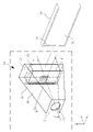
- FIG. 1 It is a perspective view which shows the skin imaging apparatus which uses the imaging assistance jig of this invention. It is an external view which shows the photographing auxiliary jig of this invention. It is a schematic diagram which shows the internal structure seen from the width direction of a photographing auxiliary jig. It is explanatory drawing of the partition plate.
- A is an explanatory diagram of a filter pad used in the first shooting mode.
- B is an explanatory diagram of a filter pad used in the second shooting mode. It is sectional drawing which follows the AA line of FIG. It is sectional drawing which follows the BB line of FIG. It is explanatory drawing of the color palette provided in the front plate. It is explanatory drawing of the insertion guide.
- the photographing assist jig 10 of the present invention is used together with a smartphone (mobile terminal) 30 owned by the user, photographs the user's own skin, and is a skin analysis application installed in the smartphone 30. It is used to easily analyze the state of.
- the smartphone 30 in the present specification also includes the smartphone 30 covered with a case or a cover.
- the main body 11 forming the outer shape of the photographing assist jig 10 has a space inside due to a plurality of side plates 14 connecting the front plate 12, the back plate 13, and the front plate 12 and the back plate 13. Is configured to form.
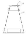
- the main body 11 is configured in a tapered shape that tapers toward the front (direction of the front plate 12) along the longitudinal direction.
- the front plate 12 is formed with a skin photographing window 12a hollowed out in a circular shape.
- a smartphone insertion slot 15a for inserting the smartphone 30 into the main body 11 is formed on the side surface of the main body 11. As shown in FIG.
- the direction indicated by the arrow x is the width direction of the photographing auxiliary jig 10 (the insertion direction of the smartphone 30), and similarly, the direction indicated by the arrow y is the longitudinal direction and the direction indicated by the arrow z is the longitudinal direction. In the height direction.
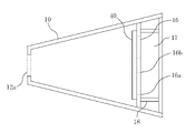
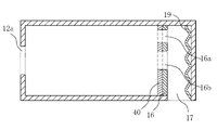
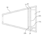
- FIG. 3 schematically shows the internal structure of the main body 11.
- the main body 11 is provided with a partition plate 16.
- the partition plate 16 is parallel to the front plate 12 and the back plate 13. Further, between the partition plate 16 and the back plate 13, a support member for supporting the smartphone 30 in the center with respect to the height direction of the main body 11 of the photographing assist jig 10 when the smartphone 30 is inserted.
- 18s are provided at the top and bottom, and the partition plate 16, the back plate 13, and the upper and lower support members 18 form a smartphone holding portion (portable terminal holding portion) 17 which is a space for holding the smartphone 30.
- the smartphone 30 inserted from the smartphone insertion slot 15a is held in this space.
- the dimension of the photographing auxiliary jig 10 is, for example, about 70 to 140 mm in the longitudinal direction corresponding to the total length.
- the front plate 12 has a square shape with a side of about 50 mm, and a circular skin photographing window 12a having a diameter of about 30 mm is provided in the center of the front plate 12. Further, the depth length (dimension in the insertion direction) of the smartphone holding portion 17 is about 60 mm. Inside the main body 11, the distance between the front plate 12 and the partition plate 16 is about 50 to 120 mm.
- the insertion port 15a has a generous size so as to be compatible with various types of smartphones 30, and has an opening having a width of about 20 mm and an opening of about 90 mm in the height direction. These dimensions can be arbitrarily determined according to the change in the form of the smartphone 30.
- the smartphone 30 currently in widespread use has a pseudo-flash function by making the display 31 emit light brighter than usual when shooting with the inner camera (see FIG. 2) 32 as a shooting means.
- the flash of the display 31 is used as a lighting means.
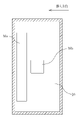
- the partition plate 16 has an opening 16a for photographing means and an opening 16b for lighting means.
- the opening 16a for the photographing means is formed in a long rectangular shape in a direction perpendicular to the insertion direction at a position far from the smartphone insertion slot 15a into which the smartphone 30 is inserted.
- the opening 16b for the lighting means is formed in the center of the partition plate 16 in a square shape having a side of about 15 mm.
- the mounting position of the inner camera 32 of the smartphone 30 varies depending on each model in the left-right direction, but in the vertical direction, it is often within a range of about 15 mm at the top, so the width is wide enough to support these many models.
- the opening is formed. Further, the opening 16b for the lighting means and the skin photographing window 12a are formed so as to face each other so that when the main body 11 is viewed from the front, the opening 16b for the lighting means fits within the contour of the skin photographing window 12a. appear.
- the position of the inner camera 32 of the smartphone 30 is different for each model, so when the smartphone 30 is inserted into the smartphone holding unit 17, shooting is performed so that the difference in camera positions different for each model can be widely absorbed.
- the position and size of the opening 16a for the means are determined.
- the position of the opening 16b for the lighting means is used so as to illuminate the skin photographing window 12a from the opposite position regardless of the model.
- the size is fixed.
- the photographing assisting jig 10 has a symmetrical shape in order to enable photographing from the left-right direction, and the photographing assisting jig 10 can be used by inverting the top and bottom in the height direction. In this way, even when the skin is inverted and used, the skin photographing window 12a can be illuminated at an appropriate position or range.
- a filter pad 40 adhered to the partition plate 16 is provided inside the main body 11 of the photographing auxiliary jig 10.
- the filter pad 40 is for illuminating a polarizing filter 41 for photographing for acquiring a polarized image with the inner camera 32 of the smartphone 30 and a flash of the display 31 of the smartphone 30 as polarized illumination light. It has a polarizing filter 42.
- the polarizing filter portion (not shown) of the polarizing filter 41 for imaging and the polarizing filter 42 for illumination is arranged so that the phase difference of the polarization is 90 degrees.
- the polarizing filter 41 for photography is fixed to the inside of the filter pad 40, and the polarizing filter 42 for illumination is enclosed in a state of being movable along the direction of the arrow. Further, the polarizing filter 42 for illumination is formed in a T-shape at both ends in the moving direction, the outer end serves as a stopper in the pushing direction with respect to the insertion direction, and the inner end in the pulling direction. The end becomes a stopper. As a result, the illumination polarizing filter 42 moves only within a predetermined range.
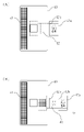
- the filter pad 40 is used in two forms according to the shooting mode. FIG.
- FIG. 5A shows a form used for performing non-reflective photographing in which reflection of illumination light on the skin surface is suppressed, and a polarizing filter 41 for imaging and a polarizing filter 42 for illumination are applied to the filter pad 40.
- a polarizing filter 41 for imaging and a polarizing filter 42 for illumination are applied to the filter pad 40.
- it is mainly used when performing spot / brightness / color shooting (first shooting mode) for analyzing skin spots, brightness, or color.
- FIG. 5B is a mode used for photographing the reflection of the illumination light on the skin surface, and only the polarizing filter 41 for photographing is applied to the filter pad 40, and the central portion is open.
- This is mainly used for texture / wrinkle photography (second photography mode) for analyzing skin texture or wrinkles.
- the polarizing filter portions of the polarizing filter 41 for imaging and the polarizing filter 42 for lighting can be suitable for capturing an image necessary for analysis, and the type, characteristics, or polarization direction of the polarizing filter portion can be determined. It can be set arbitrarily.
- the polarizing filter 42 for lighting is composed of a polarizing filter (not shown) and a knob 42a that makes the polarizing filter portion movable inside the filter pad 40.
- the knob 42a is provided with two dividing lines 42b. Using these dividing lines 42b as markers, the dividing lines 42b are aligned so that the first line is used for spot / brightness / color shooting, and the second line is used for texture / wrinkle shooting.
- the position of the filter 42 can be adjusted to switch between the first shooting mode and the second shooting mode. Further, a crease is provided so that the display 31 of the smartphone 30 can be folded at the dividing line 42b so as not to interfere with the operation of the display 31.
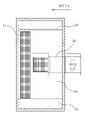
- FIG. 6 is a cross-sectional view taken along the line AA of FIG.
- a corrugated holding member 19 is provided on the back plate 13 side.
- the smartphone 30 is pressed against the partition plate 16 by the holding member 19, and the display 31 surface of the smartphone 30 and the partition plate 16 come into contact with each other without a gap, resulting in a flush state. Therefore, when shooting with the skin photographing device 20 described later, the inner side surface of the opening of the partition plate 16 and the filter pad 40 is not photographed.
- the holding member 19 can have any shape, it is preferable that the holding member 19 has a shape having a high restoring force for repeated use in addition to having a high holding force. Further, as the holding member 19, a material such as an elastic sponge may be used.
- FIG. 7 is a cross-sectional view taken along the line BB of FIG.
- the polarizing filter of the filter pad 40 is adhered so as to overlap the position of the opening of the partition plate 16.
- the polarizing filter 41 for photographing overlaps the position of the opening 16a for the photographing means
- the polarizing filter 42 for illumination overlaps the position of the opening 16b for the lighting means.
- FIG. 7 is an example of shooting spots, brightness, and color.
- the polarizing filter portion of the filter pad 40 is formed so that when the filter pad 40 is adhered to the partition plate 16, the entire surface of each corresponding opening is covered without a gap.
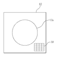
- a color palette 50 is provided inside the front plate 12 of the photographing auxiliary jig 10.
- the color palette 50 performs color correction and brightness correction of the photographed image by being photographed together with the skin.
- By providing the color palette 50 it is possible to reduce the influence of the color difference / brightness difference of the captured image caused by the difference in the camera lens, the image sensor, the display that emits the illumination light, etc., which differ depending on the model of the smartphone 30.
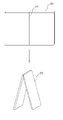
- the photographing assist jig 10 includes an insertion guide 60.
- the insertion guide 60 is used along with the back side when the smartphone 30 is inserted into the main body 11.
- the photographing assist jig 10 can be used without any inconvenience according to various usage forms of the smartphone 30.
- the insertion guide 60 is provided with a bending line 61 so that the insertion guide 60 can be bent in half from the center position.
- the dimension in the longitudinal direction of the insertion guide 60 is formed to be larger than the depth dimension of the smartphone holding portion 17 even in the folded state, and when the thickness of the smartphone 30 is thin, the insertion guide 60 can be folded and used.
- the holding power of the smartphone holding portion 17 can be increased.
- the inner surface of the main body 11 is painted black in order to reduce the reflection of the inner surface by the lighting means.
- the main body 11 may be painted with another dark color, or may be made of a material close to black. That is, it suffices if the inner side surface of the main body 11 has a structure that does not easily reflect light. In this way, by blackening the inner surface of the main body 11, the light blocking effect of the main body 11 can be improved, and the light reflected on the inner surface, which hinders the analysis of the skin, can be reduced, so that highly accurate skin analysis can be performed. can do.
- each member constituting the photographing auxiliary jig 10 a material such as wood or metal can be appropriately used in addition to a plate-shaped material such as paper or plastic such as corrugated cardboard. Moreover, it may be a combination thereof. As a matter of course, it is preferable to use a material having excellent processability from the viewpoint of manufacturing.
- the main body 11 of the photographing auxiliary jig 10 has a tapered front portion, but may have other structures.
- a structure such as a rectangular cuboid that can be manufactured more easily, or a structure that is familiar to the user such as a cylinder or a triangular injection can be used. That is, any shape can be used as long as the skin photographing window 12a and the smartphone 30 are held in parallel and the photographing distance can be kept constant.
- the photographing assist jig 10 of the first embodiment is used as the skin photographing apparatus 20
- the smartphone 30 is inserted into the main body 11 of the photographing assist jig 10, and the smartphone 30 is held by the smartphone holding portion 17 (used state). It is to be used.
- the skin photographing apparatus 20 takes a picture of the skin surface by bringing the front plate 12 into contact with the skin so as to press it against the skin in the state of use.
- the inside of the main body 11 of the shooting auxiliary jig 10 is in a light-shielded state in which the light outside the main body 11 is blocked, and the flash of the display 31 of the smartphone 30 which is the illumination light is used for the lighting means. Only the light that is applied to the skin in the skin photographing window 12a through the opening 16b and reflected on the surface of the skin or the surface layer portion of the skin is incident on the inner camera 32 of the smartphone 30 through the opening 16a for the photographing means. become.
- the skin photographing apparatus 20 can take an image in a state of being in contact with the skin so that the ambient light, which is the external light of the photographing assisting jig 10, does not enter the inside of the photographing assisting jig 10, the display 31 can be used. It is possible to prevent unnecessary light other than the light of the above from being photographed by the inner camera 32. Then, the skin analysis application of the smartphone 30 uses the image data captured in this way to perform analysis corresponding to the photographing mode.
- the photographing assist jig 10 is used. After the filter pad 40 is in the form of (A) of FIG. 5, the first shooting mode is executed. Further, when it is desired to know the state of the texture or wrinkles of the skin, the filter pad 40 of the photographing auxiliary jig 10 is made into the form of FIG. 5B, and then the second photographing mode is executed.
- the skin analysis application uses different images for each shooting mode to analyze the skin corresponding to the shooting mode.
- non-reflective shooting is performed by irradiating the skin of the face with polarized illumination light polarized in a certain direction, and the brightness of the skin surface and the stains / brightness caused by the pigment contained in the skin surface layer are taken. The state of color can be analyzed.
- the skin is photographed by irradiating the skin with illumination light that does not pass through the polarizing filter, and the degree of reflection of the illumination light caused by the fine unevenness of the skin surface is photographed. The condition of wrinkles can be analyzed.
- the skin analysis by the skin analysis application of the smartphone 30 can be performed by, for example, the method described in Japanese Patent Publication No. 3-125322, which is a known technique.
- the skin photographing apparatus 20 of the present invention acquires an image of the skin used for skin analysis by using only the necessary illumination light in a state where the photographing space is shielded, and the image data photographed in this way. Is used for analysis. Therefore, even if the shooting location and time zone are different, the shooting environment does not change for each shooting, and highly accurate analysis can be performed. Then, the user can meaningfully manage the skin and select cosmetics in daily life by using the analysis result by the skin photographing apparatus 20.
- the main body 11 of the photographing assist jig 10 is made symmetrical, it is easy to use regardless of whether the skin on the left or right side of the face is photographed when the skin photographing device 20 is used.
- the orientation can be selected according to the user's taste and dominant arm.
- the skin photographing device 20 can be used not only for the skin of the face but also for other parts. For example, by using the skin imaging device 20 for the head, arms, and the like, it is possible to analyze the skin surface of the imaging site. Since the skin photographing apparatus 20 of the present invention can keep the shooting distance and the shooting area constant, for example, when shooting the head of the scalp, even if it is difficult to directly operate the display 31, timer shooting is performed on the application side. It is easy to take the necessary image by performing.
- the image taken by the skin photographing device 20 may be transmitted to a server such as a cloud, and a program for performing skin analysis may be executed on the cloud.
- the skin photographing apparatus 20 of the third embodiment is used by attaching the attachment 70 to the imaging assisting jig 10 as shown in FIG. 10, and the amount of sebum on the skin is used. This is to perform sebum photography (third photography mode) to analyze.
- the attachment 70 is formed in a cap shape along the shape of the tip portion of the main body 11.
- the attachment 70 has a sebum reaction sheet 71 that is used by inserting it into an insertion portion (not shown) on the front surface of the attachment 70.
- the sebum reaction sheet 71 is used by being attached to the attachment 70 when executing the third photographing mode.
- the inner surface of the front surface of the attachment 70 is open at the center so that the sebum reaction portion 71a of the sebum reaction sheet 71 is exposed when the sebum reaction sheet 71 is attached.
- the third photographing mode when the attachment 70 to which the sebum reaction sheet 71 is attached is put on the main body 11, the sebum reaction portion 71a of the sebum reaction sheet 71 exposed on the inner surface of the front surface of the attachment 70 is photographed.
- the shape of the insertion portion of the attachment 70 is such that the whole is shaped like a so-called pocket, and the sebum reaction portion 71a is formed so as to be arranged exactly in the center when the sebum reaction sheet 71 is inserted. There is.
- the width of the insertion portion is formed to be slightly wider than the width of the sebum reaction sheet 71, and the inner side surface in the width direction of the insertion portion serves as a guide when inserting the sebum reaction sheet 71, so that the sebum reaction sheet 71 can be smoothly inserted. Can be inserted into.
- the user contacts the sebum reaction sheet 71 with the skin for a few seconds before executing the third shooting mode in the application of the smartphone 30, and the sebum reaction sheet 71 reacts with the sebum of the skin to change the color.
- the sebum reaction sheet 71 is attached to the attachment 70.
- the attachment 70 is put on the tip of the photographing auxiliary jig 10, and in the skin analysis application of the smartphone 30, a third photographing mode, which is the same non-reflective photographing as the first photographing mode, is executed.
- the sebum reaction portion 71a of the sebum reaction sheet 71 is photographed in a form in which the reflection on the surface is reduced, and the amount of sebum can be analyzed based on the photographed image.
- the inside of the photographing assisting jig 10 is similarly similar to the skin photographing apparatus 20 of the second embodiment. Is shielded from light, so that unnecessary light other than the light from the display 31 is not photographed, and the amount of sebum can be analyzed with high accuracy.
- the partition plate 16 constituting the smartphone holding portion 17 with the back plate 13 is one, but in the fourth embodiment shown in FIG. 12, the partition plate 16 is configured as two. ..
- a partition portion is composed of two partition plates 16 having the same shape, and the partition plates 16 are arranged in parallel with each other so as to form a narrow space.
- the filter pad 40 is detachably stored in this space.
- the opening of the photographing means and the opening for the lighting means of each of the partition plates 16 are formed at positions facing the openings of one of the partition plates, and form the openings of the two partition plates 16.
- the filter pad 40 of the present embodiment uses two different filter pads 40.
- FIG. 13A is used in the first photographing mode, and has a built-in polarizing filter for photographing means and a polarizing filter for lighting means. Further, FIG. 13B is used in the second photographing mode, has a built-in polarizing filter for photographing means, and has an open central portion.
- a filter pad insertion port 15b for inserting the filter pad 40 is formed on the side surface of the main body 11 of the photographing assist jig 10 of the present embodiment. Further, although omitted in FIG. 13, the filter pad insertion port 15b is provided with a cover to prevent external light from entering.
- the user switches the filter pad 40 between the first shooting mode and the second shooting mode, and uses the filter pad 40 corresponding to the shooting mode as the shooting assist jig 10. It is inserted inside the main body 11.
- the photographing assist jig 10 and the skin photographing apparatus 20 of each of the above embodiments are configured to use the inner camera 32 of the smartphone 30, but may be configured to use the outer camera (not shown) of the smartphone 30. Since the performance of the outer camera is generally higher than that of the inner camera 32 of the smartphone 30, there is an advantage that the use of the outer camera enables highly accurate skin analysis using high-quality images. In this case, in order to support various smartphones 30, it is desirable to provide a filter pad 40 different from the filter pad 40 of each embodiment.
- the skin photographing apparatus 20 uses a smartphone 30, but a terminal such as a tablet may be used as long as it has the same functions as the smartphone 30 in the present specification. Since the photographing auxiliary jig 10 has a simple structure and can be easily manufactured to an arbitrary size, it can be manufactured according to the size of the tablet. Even in this case, since the skin photographing apparatus 20 has the necessary functions as in each of the above-described embodiments, it is possible to easily perform imaging for skin analysis.
- each member of the photographing auxiliary jig 10 may be joined and integrated with an adhesive or the like as described above, or may have an assembled structure that can be partially disassembled. If it can be stored compactly as an assembled structure, for example, it can be used on the go, and the user can use the skin photographing apparatus 20 of the present invention every day in order to manage the condition of the skin. ..
Landscapes
- Health & Medical Sciences (AREA)
- Life Sciences & Earth Sciences (AREA)
- Physics & Mathematics (AREA)
- General Physics & Mathematics (AREA)
- Engineering & Computer Science (AREA)
- Surgery (AREA)
- General Health & Medical Sciences (AREA)
- Heart & Thoracic Surgery (AREA)
- Medical Informatics (AREA)
- Molecular Biology (AREA)
- Pathology (AREA)
- Animal Behavior & Ethology (AREA)
- Biomedical Technology (AREA)
- Public Health (AREA)
- Veterinary Medicine (AREA)
- Biophysics (AREA)
- Multimedia (AREA)
- Dermatology (AREA)
- Measuring And Recording Apparatus For Diagnosis (AREA)
- Measurement Of The Respiration, Hearing Ability, Form, And Blood Characteristics Of Living Organisms (AREA)
- Closed-Circuit Television Systems (AREA)
Abstract
Description
本発明の撮影補助治具10は、図1に示すように、ユーザが所有するスマートフォン(携帯端末)30とともに用いられ、ユーザ自身の肌を撮影し、スマートフォン30にインストールされた肌分析アプリケーションで肌の状態を簡易に分析するために用いられる。なお、本明細書におけるスマートフォン30には、ケースやカバーで覆われているスマートフォン30も含まれる。
図1及び図2に戻り、上記第1実施形態の撮影補助治具10を肌撮影装置20として使用する場合を説明する。図1及び図2に示すように、肌撮影装置20は、スマートフォン30を撮影補助治具10の本体11の内部に挿入し、スマートフォン30がスマートフォン保持部17に保持された状態(使用状態)で使用するものである。肌撮影装置20は、使用状態において、正面板12を肌に押し当てるように接触させて肌表面を撮影する。すなわち、撮影の際には、撮影補助治具10の本体11の内部が、本体11の外部の光を遮断した遮光状態となり、照明光であるスマートフォン30のディスプレイ31のフラッシュが、照明手段用の開口16bを介して肌撮影窓12a内の肌に照射され、肌の表面或いは肌の表層部分で反射した光のみが、撮影手段用の開口16aを介してスマートフォン30の内側カメラ32に入射することになる。このように、肌撮影装置20は、撮影補助治具10の外部の光である環境光が撮影補助治具10の内部に侵入しないように肌に接触させた状態で撮影できるため、ディスプレイ31からの光以外の不要な光を内側カメラ32で撮影してしまうことを防ぐことができる。そして、スマートフォン30の肌分析アプリケーションは、このように撮影された画像データを用いて、撮影モードに対応する分析を行う。
第3実施形態の肌撮影装置20は、第2実施形態の肌撮影装置20とは異なり、図10に示すように、アタッチメント70を撮影補助治具10に装着して使用し、肌の皮脂量を分析する皮脂撮影(第3の撮影モード)を行うものである。図10及び図11に示すように、アタッチメント70は、本体11の先端部の形状に沿ってキャップ状に形成されている。また、アタッチメント70は、アタッチメント70の前面の挿入部(図示しない)に挿入して使用する皮脂反応シート71を有している。皮脂反応シート71は、第3の撮影モードを実行する際にアタッチメント70に装着して使用する。アタッチメント70の前面の内側面は、皮脂反応シート71を装着したときに、皮脂反応シート71の皮脂反応部71aが露出するように、中央部が開口している。第3の撮影モードでは、皮脂反応シート71が装着されたアタッチメント70を本体11に被せたときに、アタッチメント70の前面の内側面に露出した皮脂反応シート71の皮脂反応部71aを撮影する。なお、アタッチメント70の挿入部の形状は、全体がいわゆるポケットのような形状をしており、皮脂反応シート71を挿入したときに、皮脂反応部71aがちょうど中央に配置されるように形成されている。また、挿入部の幅は、皮脂反応シート71の幅より僅かに広く形成され、挿入部の幅方向の内側面が皮脂反応シート71を挿入する際のガイドとなるため、皮脂反応シート71をスムーズに挿入できる。
上記実施形態では、背面板13との間でスマートフォン保持部17を構成する仕切り板16を1枚としているが、図12に示す第4実施形態では、仕切り板16を2枚とした構成としている。図12では、同一形状の2枚の仕切り板16によって、仕切り部が構成されており、それらの仕切り板16は幅の狭い空間をなすように互いに平行に配置されている。フィルタパッド40は、この空間に着脱自在に収納される。また、それぞれの仕切り板16の撮影手段の開口と照明手段用の開口は、一方の仕切り板の開口と対向する位置に形成されており、2枚の仕切り板16の開口部を構成する。本実施形態のフィルタパッド40は、図13に示すように、2つの異なるフィルタパッド40を使用する。図13の(A)は、第1の撮影モードで使用されるものであり、撮影手段用の偏光フィルタと照明手段用の偏光フィルタが内蔵されている。また、図13の(B)は、第2の撮影モードで使用されるものであり、撮影手段用の偏光フィルタが内蔵され、中央部は開口されている。
11 本体
12 正面板
12a 肌撮影窓
13 背面板
14 側面板
15a スマートフォン挿入口
15b フィルタパッド挿入口
16 仕切り板
16a 撮影手段用の開口
16b 照明手段用の開口
17 スマートフォン保持部
18 支持部材
19 保持部材
20 肌撮影装置
30 スマートフォン
31 ディスプレイ
32 内側カメラ
40 フィルタパッド
41 撮影用偏光フィルタ
42 照明用偏光フィルタ
42a つまみ
42b 区切り線
50 カラーパレット
60 挿入ガイド
61 折り曲げ線
70 アタッチメント
71 皮脂反応シート
71a 皮脂反応部
Claims (10)
- 撮影手段と照明手段とを有する携帯端末で肌を撮影するために用いられ、正面板と背面板と複数の側面板とにより本体を構成する撮影補助治具において、
前記正面板に形成される肌撮影窓と、
前記本体の内部には空間が形成されており、前記携帯端末を前記本体の内部に挿入するための挿入口と、
前記本体の内部には、前記撮影手段用の開口部と前記撮影窓と対向する位置に設けられた前記照明手段用の開口部とを有する仕切り部が、前記正面板と平行に設けられており、前記仕切り部及び前記背面板との間に形成される空間において、前記本体の内部に挿入された前記携帯端末を保持する携帯端末保持部と、
を備える撮影補助治具。 - 前記仕切り部において、
前記撮影手段用の開口部は、前記挿入口から遠い側の位置に、前記携帯端末の挿入方向に対して垂直な方向に長く形成され、
前記照明手段用の開口部は、中央に形成される請求項1に記載の撮影補助治具。 - 前記撮影手段用の撮影用偏光フィルタと、
前記携帯端末のディスプレイがフラッシュとして機能する場合に、前記フラッシュを偏光照明光として用いるための、前記照明手段用の照明用偏光フィルタとを備え、
前記撮影用偏光フィルタは、前記撮影手段用の開口部と重なるように配置され、
前記照明用偏光フィルタは、前記照明手段用の開口部と重なるように配置される請求項2に記載の撮影補助治具。 - 前記本体の前記正面板の内側に設けられ、前記携帯端末で撮影された画像の色補正及び明るさ補正を行うためのカラーパレットを備える請求項3に記載の撮影補助治具。
- 前記携帯端末を前記本体の内部に挿入する際に、前記携帯端末に添えて使用する挿入ガイドを備える請求項3または4に記載の撮影補助治具。
- 前記本体の前記正面板側に取り付けるアタッチメントを備え、
前記アタッチメントには、肌の皮脂量を測定するための皮脂反応シートが装着される請求項3から5のいずれか1項に記載の撮影補助治具。 - 請求項3から5のいずれか1項に記載の撮影補助治具を備える肌撮影装置であって、
前記携帯端末が前記携帯端末保持部に保持された使用状態において、前記撮影窓の輪郭を肌に接触させて肌表面を撮影する肌撮影装置。 - 前記本体の内部は、前記撮影窓の輪郭を肌に接触させることにより、前記本体の外部の光を遮断した遮光状態となり、前記遮光状態において、前記ディスプレイのフラッシュのみを用いて前記肌表面を撮影する請求項7に記載の肌撮影装置。
- 少なくとも2つの異なる撮影モードを備え、前記撮影モードには、前記撮影用偏光フィルタ及び前記照明用偏光フィルタを用いた第1の撮影モードと、前記撮影用偏光フィルタのみを用いた第2の撮影モードとが含まれる請求項7または8に記載の肌撮影装置。
- 請求項6に記載の撮影補助治具を備える肌撮影装置であって、
前記携帯端末が前記携帯端末保持部に保持され、かつ、前記本体にアタッチメントを取り付けた状態において、前記撮影用偏光フィルタ及び前記照明用偏光フィルタを用いた第3の撮影モードを実行する肌撮影装置。
Priority Applications (7)
| Application Number | Priority Date | Filing Date | Title |
|---|---|---|---|
| MX2023008037A MX2023008037A (es) | 2021-01-05 | 2021-01-05 | Herramienta de ayuda para la fotografía y dispositivo para fotografiar la piel. |
| JP2021507087A JP6891360B1 (ja) | 2021-01-05 | 2021-01-05 | 撮影補助治具及び肌撮影装置 |
| AU2021416750A AU2021416750A1 (en) | 2021-01-05 | 2021-01-05 | Imaging assistance tool and skin imaging device |
| PCT/JP2021/000128 WO2022149193A1 (ja) | 2021-01-05 | 2021-01-05 | 撮影補助治具及び肌撮影装置 |
| EP21917421.6A EP4276529B1 (en) | 2021-01-05 | 2021-01-05 | Imaging assistance tool and skin imaging device |
| CN202180094128.7A CN116897319A (zh) | 2021-01-05 | 2021-01-05 | 拍摄辅助夹具及皮肤拍摄装置 |
| US18/218,113 US12346003B2 (en) | 2021-01-05 | 2023-07-05 | Photography aid tool and skin photographing device |
Applications Claiming Priority (1)
| Application Number | Priority Date | Filing Date | Title |
|---|---|---|---|
| PCT/JP2021/000128 WO2022149193A1 (ja) | 2021-01-05 | 2021-01-05 | 撮影補助治具及び肌撮影装置 |
Related Child Applications (1)
| Application Number | Title | Priority Date | Filing Date |
|---|---|---|---|
| US18/218,113 Continuation US12346003B2 (en) | 2021-01-05 | 2023-07-05 | Photography aid tool and skin photographing device |
Publications (1)
| Publication Number | Publication Date |
|---|---|
| WO2022149193A1 true WO2022149193A1 (ja) | 2022-07-14 |
Family
ID=76429648
Family Applications (1)
| Application Number | Title | Priority Date | Filing Date |
|---|---|---|---|
| PCT/JP2021/000128 Ceased WO2022149193A1 (ja) | 2021-01-05 | 2021-01-05 | 撮影補助治具及び肌撮影装置 |
Country Status (7)
| Country | Link |
|---|---|
| US (1) | US12346003B2 (ja) |
| EP (1) | EP4276529B1 (ja) |
| JP (1) | JP6891360B1 (ja) |
| CN (1) | CN116897319A (ja) |
| AU (1) | AU2021416750A1 (ja) |
| MX (1) | MX2023008037A (ja) |
| WO (1) | WO2022149193A1 (ja) |
Families Citing this family (2)
| Publication number | Priority date | Publication date | Assignee | Title |
|---|---|---|---|---|
| JP7827597B2 (ja) * | 2022-09-21 | 2026-03-10 | 富士フイルムメディカル株式会社 | 撮影補助装置及び撮影補助方法 |
| WO2024196840A1 (en) * | 2023-03-20 | 2024-09-26 | Un Haluk | Support device for close-up photography with adjustable lighting and fixed focus distance |
Citations (5)
| Publication number | Priority date | Publication date | Assignee | Title |
|---|---|---|---|---|
| JP2013257518A (ja) | 2012-06-14 | 2013-12-26 | Hitachi Maxell Ltd | レンズモジュールおよび撮影方法 |
| US9427187B2 (en) * | 2011-01-04 | 2016-08-30 | L'oreal | System for analysing the skin and associated method |
| JP2016532512A (ja) * | 2013-08-28 | 2016-10-20 | センスブレス・アクチボラゲットSensebreath Ab | 呼吸分析およびトレーニングアセンブリ |
| WO2019163373A1 (ja) * | 2018-02-21 | 2019-08-29 | ヤーマン株式会社 | 撮像システム、撮像方法、カメラアダプタ及びプログラム |
| WO2020162262A1 (ja) * | 2019-02-08 | 2020-08-13 | 富士フイルム富山化学株式会社 | 薬剤識別システム、薬剤識別装置、薬剤識別方法及びプログラム |
Family Cites Families (5)
| Publication number | Priority date | Publication date | Assignee | Title |
|---|---|---|---|---|
| CN103181154A (zh) * | 2010-10-29 | 2013-06-26 | 加利福尼亚大学董事会 | 用于成像的手机显微镜装置和方法 |
| US20140378810A1 (en) * | 2013-04-18 | 2014-12-25 | Digimarc Corporation | Physiologic data acquisition and analysis |
| JP6528396B2 (ja) * | 2014-12-10 | 2019-06-12 | 富士ゼロックス株式会社 | 撮影用ユニットおよび撮影システム |
| EP3313272A4 (en) * | 2015-06-23 | 2019-02-20 | Metaoptima Technology Inc. | APPARATUS FOR IMAGING THE SKIN |
| WO2019173121A1 (en) * | 2018-03-08 | 2019-09-12 | The Procter & Gamble Company | Tool for use with image capturing device for capturing quality image and method thereof |
-
2021
- 2021-01-05 MX MX2023008037A patent/MX2023008037A/es unknown
- 2021-01-05 CN CN202180094128.7A patent/CN116897319A/zh active Pending
- 2021-01-05 JP JP2021507087A patent/JP6891360B1/ja active Active
- 2021-01-05 AU AU2021416750A patent/AU2021416750A1/en active Pending
- 2021-01-05 EP EP21917421.6A patent/EP4276529B1/en active Active
- 2021-01-05 WO PCT/JP2021/000128 patent/WO2022149193A1/ja not_active Ceased
-
2023
- 2023-07-05 US US18/218,113 patent/US12346003B2/en active Active
Patent Citations (5)
| Publication number | Priority date | Publication date | Assignee | Title |
|---|---|---|---|---|
| US9427187B2 (en) * | 2011-01-04 | 2016-08-30 | L'oreal | System for analysing the skin and associated method |
| JP2013257518A (ja) | 2012-06-14 | 2013-12-26 | Hitachi Maxell Ltd | レンズモジュールおよび撮影方法 |
| JP2016532512A (ja) * | 2013-08-28 | 2016-10-20 | センスブレス・アクチボラゲットSensebreath Ab | 呼吸分析およびトレーニングアセンブリ |
| WO2019163373A1 (ja) * | 2018-02-21 | 2019-08-29 | ヤーマン株式会社 | 撮像システム、撮像方法、カメラアダプタ及びプログラム |
| WO2020162262A1 (ja) * | 2019-02-08 | 2020-08-13 | 富士フイルム富山化学株式会社 | 薬剤識別システム、薬剤識別装置、薬剤識別方法及びプログラム |
Non-Patent Citations (1)
| Title |
|---|
| See also references of EP4276529A4 |
Also Published As
| Publication number | Publication date |
|---|---|
| EP4276529A1 (en) | 2023-11-15 |
| US20240184184A1 (en) | 2024-06-06 |
| EP4276529B1 (en) | 2025-11-19 |
| JPWO2022149193A1 (ja) | 2022-07-14 |
| MX2023008037A (es) | 2023-09-18 |
| JP6891360B1 (ja) | 2021-06-18 |
| US12346003B2 (en) | 2025-07-01 |
| CN116897319A (zh) | 2023-10-17 |
| AU2021416750A1 (en) | 2023-08-17 |
| EP4276529A4 (en) | 2024-03-20 |
Similar Documents
| Publication | Publication Date | Title |
|---|---|---|
| US12346003B2 (en) | Photography aid tool and skin photographing device | |
| US9473653B2 (en) | Image reading apparatus | |
| KR20100036310A (ko) | 피사체 상에 내재한 불가시 이미지를 관측하면서 간이하게 촬영할 수 있는 장치 및 이를 이용하는 방법 | |
| JP2005181598A (ja) | 撮影補助装置及び撮影方法 | |
| WO2016017054A1 (ja) | 撮像装置 | |
| JP2021515640A (ja) | 良質画像を取込むための画像取込デバイスと共に使用するためのツール及びその方法 | |
| JPH0669948U (ja) | レンズ付きフィルム(カメラ)におけるキャラクタ画像表示装置 | |
| JP2015031901A (ja) | 補助レンズユニット | |
| JP2003270705A (ja) | カメラ | |
| JPH06338987A (ja) | スキャナ装置 | |
| CN201422133Y (zh) | 电子相框 | |
| JP2009063612A (ja) | カメラ | |
| JP2004325764A (ja) | 沈胴式レンズ鏡筒 | |
| JP2010049004A (ja) | 撮影補助器具 | |
| KR101473088B1 (ko) | 전자 확대경 | |
| KR20180002607U (ko) | 근접 촬영용 사진 촬영대 | |
| JP2017138510A (ja) | 画像読取補助装置 | |
| JP6546964B2 (ja) | 携帯型プリンタ | |
| CN101854449A (zh) | 电子相框 | |
| JPH0411131Y2 (ja) | ||
| JP3180980U (ja) | 工事写真用情報表示具 | |
| WO2010067879A1 (ja) | プリント写真撮像用器具、及びプリント写真撮像用器具セット | |
| JP4178298B2 (ja) | カメラ | |
| JP3759978B2 (ja) | レンズ付きフイルムユニット | |
| JP3123725B2 (ja) | レンズ付きフイルムユニット |
Legal Events
| Date | Code | Title | Description |
|---|---|---|---|
| ENP | Entry into the national phase |
Ref document number: 2021507087 Country of ref document: JP Kind code of ref document: A |
|
| 121 | Ep: the epo has been informed by wipo that ep was designated in this application |
Ref document number: 21917421 Country of ref document: EP Kind code of ref document: A1 |
|
| WWE | Wipo information: entry into national phase |
Ref document number: MX/A/2023/008037 Country of ref document: MX |
|
| REG | Reference to national code |
Ref country code: BR Ref legal event code: B01A Ref document number: 112023013428 Country of ref document: BR |
|
| WWE | Wipo information: entry into national phase |
Ref document number: 12023552158 Country of ref document: PH Ref document number: 202317052430 Country of ref document: IN |
|
| NENP | Non-entry into the national phase |
Ref country code: DE |
|
| ENP | Entry into the national phase |
Ref document number: 2021917421 Country of ref document: EP Effective date: 20230807 |
|
| ENP | Entry into the national phase |
Ref document number: 2021416750 Country of ref document: AU Date of ref document: 20210105 Kind code of ref document: A |
|
| WWE | Wipo information: entry into national phase |
Ref document number: 202180094128.7 Country of ref document: CN |
|
| ENP | Entry into the national phase |
Ref document number: 112023013428 Country of ref document: BR Kind code of ref document: A2 Effective date: 20230704 |
|
| WWE | Wipo information: entry into national phase |
Ref document number: 11202305864P Country of ref document: SG |
|
| WWG | Wipo information: grant in national office |
Ref document number: 2021917421 Country of ref document: EP |