WO2022149282A1 - 端末、無線通信方法及び基地局 - Google Patents
端末、無線通信方法及び基地局 Download PDFInfo
- Publication number
- WO2022149282A1 WO2022149282A1 PCT/JP2021/000569 JP2021000569W WO2022149282A1 WO 2022149282 A1 WO2022149282 A1 WO 2022149282A1 JP 2021000569 W JP2021000569 W JP 2021000569W WO 2022149282 A1 WO2022149282 A1 WO 2022149282A1
- Authority
- WO
- WIPO (PCT)
- Prior art keywords
- transmission
- information
- data
- unit
- resource
- Prior art date
- Legal status (The legal status is an assumption and is not a legal conclusion. Google has not performed a legal analysis and makes no representation as to the accuracy of the status listed.)
- Ceased
Links
Images









Classifications
-
- H—ELECTRICITY
- H04—ELECTRIC COMMUNICATION TECHNIQUE
- H04B—TRANSMISSION
- H04B7/00—Radio transmission systems, i.e. using radiation field
- H04B7/02—Diversity systems; Multi-antenna system, i.e. transmission or reception using multiple antennas
- H04B7/04—Diversity systems; Multi-antenna system, i.e. transmission or reception using multiple antennas using two or more spaced independent antennas
- H04B7/0404—Diversity systems; Multi-antenna system, i.e. transmission or reception using multiple antennas using two or more spaced independent antennas the mobile station comprising multiple antennas, e.g. to provide uplink diversity
-
- H—ELECTRICITY
- H04—ELECTRIC COMMUNICATION TECHNIQUE
- H04W—WIRELESS COMMUNICATION NETWORKS
- H04W4/00—Services specially adapted for wireless communication networks; Facilities therefor
- H04W4/70—Services for machine-to-machine communication [M2M] or machine type communication [MTC]
-
- H—ELECTRICITY
- H04—ELECTRIC COMMUNICATION TECHNIQUE
- H04B—TRANSMISSION
- H04B7/00—Radio transmission systems, i.e. using radiation field
- H04B7/02—Diversity systems; Multi-antenna system, i.e. transmission or reception using multiple antennas
- H04B7/022—Site diversity; Macro-diversity
- H04B7/024—Co-operative use of antennas of several sites, e.g. in co-ordinated multipoint or co-operative multiple-input multiple-output [MIMO] systems
-
- H—ELECTRICITY
- H04—ELECTRIC COMMUNICATION TECHNIQUE
- H04L—TRANSMISSION OF DIGITAL INFORMATION, e.g. TELEGRAPHIC COMMUNICATION
- H04L5/00—Arrangements affording multiple use of the transmission path
- H04L5/0001—Arrangements for dividing the transmission path
- H04L5/0014—Three-dimensional division
- H04L5/0023—Time-frequency-space
-
- H—ELECTRICITY
- H04—ELECTRIC COMMUNICATION TECHNIQUE
- H04L—TRANSMISSION OF DIGITAL INFORMATION, e.g. TELEGRAPHIC COMMUNICATION
- H04L5/00—Arrangements affording multiple use of the transmission path
- H04L5/003—Arrangements for allocating sub-channels of the transmission path
- H04L5/0032—Distributed allocation, i.e. involving a plurality of allocating devices, each making partial allocation
- H04L5/0035—Resource allocation in a cooperative multipoint environment
-
- H—ELECTRICITY
- H04—ELECTRIC COMMUNICATION TECHNIQUE
- H04L—TRANSMISSION OF DIGITAL INFORMATION, e.g. TELEGRAPHIC COMMUNICATION
- H04L5/00—Arrangements affording multiple use of the transmission path
- H04L5/003—Arrangements for allocating sub-channels of the transmission path
- H04L5/0044—Allocation of payload; Allocation of data channels, e.g. PDSCH or PUSCH
-
- H—ELECTRICITY
- H04—ELECTRIC COMMUNICATION TECHNIQUE
- H04L—TRANSMISSION OF DIGITAL INFORMATION, e.g. TELEGRAPHIC COMMUNICATION
- H04L5/00—Arrangements affording multiple use of the transmission path
- H04L5/003—Arrangements for allocating sub-channels of the transmission path
- H04L5/0048—Allocation of pilot signals, i.e. of signals known to the receiver
- H04L5/0051—Allocation of pilot signals, i.e. of signals known to the receiver of dedicated pilots, i.e. pilots destined for a single user or terminal
-
- H—ELECTRICITY
- H04—ELECTRIC COMMUNICATION TECHNIQUE
- H04W—WIRELESS COMMUNICATION NETWORKS
- H04W72/00—Local resource management
- H04W72/12—Wireless traffic scheduling
- H04W72/1263—Mapping of traffic onto schedule, e.g. scheduled allocation or multiplexing of flows
- H04W72/1268—Mapping of traffic onto schedule, e.g. scheduled allocation or multiplexing of flows of uplink data flows
-
- H—ELECTRICITY
- H04—ELECTRIC COMMUNICATION TECHNIQUE
- H04W—WIRELESS COMMUNICATION NETWORKS
- H04W72/00—Local resource management
- H04W72/20—Control channels or signalling for resource management
-
- H—ELECTRICITY
- H04—ELECTRIC COMMUNICATION TECHNIQUE
- H04W—WIRELESS COMMUNICATION NETWORKS
- H04W92/00—Interfaces specially adapted for wireless communication networks
- H04W92/16—Interfaces between hierarchically similar devices
- H04W92/18—Interfaces between hierarchically similar devices between terminal devices
Definitions
- This disclosure relates to terminals, wireless communication methods and base stations in next-generation mobile communication systems.
- LTE Long Term Evolution
- UMTS Universal Mobile Telecommunications System
- 3GPP Rel.10-14 LTE-Advanced (3GPP Rel.10-14) has been specified for the purpose of further increasing the capacity and sophistication of LTE (Third Generation Partnership Project (3GPP) Release (Rel.) 8, 9).
- a successor system to LTE for example, 5th generation mobile communication system (5G), 5G + (plus), 6th generation mobile communication system (6G), New Radio (NR), 3GPP Rel.15 or later, etc.
- 5G 5th generation mobile communication system
- 6G 6th generation mobile communication system
- NR New Radio
- the MIMO (Multi Input Multi Output) system is supported as a wireless communication technology that transmits and receives data with multiple antennas and improves the data rate (frequency utilization efficiency).
- a MIMO system a plurality of transmission / reception antennas are prepared in a transceiver, and different transmission information sequences are simultaneously transmitted from different transmission antennas.
- SU-MIMO Single User MIMO
- MU-MIMO Multiple User MIMO
- UL transmission of a certain terminal is performed using the antennas / antenna ports of a plurality of terminals including the terminal (UE cooperative MIMO).
- the present disclosure provides a terminal, a wireless communication method, and a base station capable of appropriately controlling communication even when communication is performed using antennas / antenna ports of a plurality of UEs. It is one of the purposes.
- the terminal is divided based on at least one of a receiving unit that receives information about a schedule and one of UL data, which is a transport block unit, a code word unit, a code block unit, and a bit unit. It has a transmission unit that transmits information about UL data of the unit to another terminal, and a control unit that controls to transmit the UL data in cooperation with the other terminal based on the information about the schedule. It is characterized by that.
- communication can be appropriately controlled even when communication is performed using the antennas / antenna ports of a plurality of UEs.
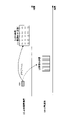
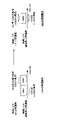
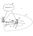
- FIG. 1A and 1B are diagrams showing an example of MU-MIMO and UE cooperative MIMO.
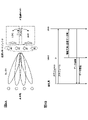
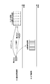
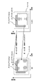
- FIG. 2 is a diagram showing an example of an antenna port of UE cooperative MIMO.
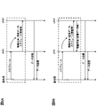
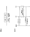
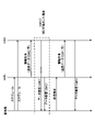
- FIG. 3 is a diagram showing an example of a synchronization signal in UE cooperative MIMO according to the first embodiment.
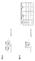
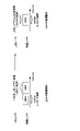
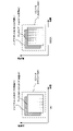
- 4A and 4B are diagrams showing an example of communication control in UE cooperative MIMO according to the second embodiment.
- FIG. 5 is a diagram showing another example of communication control in UE cooperative MIMO according to the second embodiment.
- FIG. 6 is a diagram showing an example of resource allocation in UE cooperative MIMO according to the third embodiment.
- 7A and 7B are diagrams showing an example of communication control in UE cooperative MIMO according to the fourth embodiment.
- FIG. 8A and 8B are diagrams showing other examples of communication control in UE-coordinated MIMO according to the fourth embodiment.
- 9A and 9B are diagrams showing other examples of communication control in UE-coordinated MIMO according to the fourth embodiment.
- 10A and 10B are diagrams showing an example of DCI used for UE cooperative MIMO according to the fourth embodiment.
- FIG. 11 is a diagram showing another example of communication control in UE cooperative MIMO according to the fourth embodiment.
- FIG. 12 is a diagram showing another example of communication control in UE cooperative MIMO according to the fourth embodiment.
- 13A and 13B are diagrams showing an example of control of information sharing between UEs in UE cooperative MIMO according to the fifth embodiment.
- FIG. 14 is a diagram showing another example of control of information sharing between UEs in UE cooperative MIMO according to the fifth embodiment.
- FIG. 15 is a diagram showing another example of control of information sharing between UEs in UE cooperative MIMO according to the fifth embodiment.
- 16A and 16B are diagrams showing another example of control of information sharing between UEs in UE cooperative MIMO according to the fifth embodiment.
- 17A and 17B are diagrams showing another example of control of information sharing between UEs in UE cooperative MIMO according to the fifth embodiment.
- 18A and 18B are diagrams showing an example of SRS transmission in UE cooperative MIMO according to the sixth embodiment.
- FIG. 19 is a diagram showing an example of SRS transmission and PUSCH transmission in UE cooperative MIMO according to the sixth embodiment.
- FIG. 20 is a diagram showing other examples of SRS transmission and PUSCH transmission in UE cooperative MIMO according to the sixth embodiment.
- FIG. 21 is a diagram showing other examples of SRS transmission and PUSCH transmission in UE cooperative MIMO according to the sixth embodiment.
- FIG. 22 is a diagram showing other examples of SRS transmission and PUSCH transmission in UE cooperative MIMO according to the sixth embodiment.
- FIG. 23 is a diagram showing an example of retransmission control in UE cooperative MIMO according to the seventh embodiment.
- FIG. 24 is a diagram showing another example of retransmission control in UE cooperative MIMO according to the seventh embodiment.
- FIG. 25 is a diagram showing an example of a schematic configuration of a wireless communication system according to an embodiment.
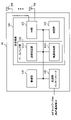
- FIG. 26 is a diagram showing an example of the configuration of the base station according to the embodiment.
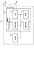
- FIG. 27 is a diagram showing an example of the configuration of the user terminal according to the embodiment.
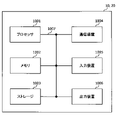
- FIG. 28 is a diagram showing an example of the hardware configuration of the base station and the user terminal according to the embodiment.
- MIMO expansion In future wireless communication systems, it is being considered to increase the number of antennas / antenna ports (hereinafter, also referred to as antenna ports) of terminals to improve the communication throughput. On the other hand, when increasing the number of antenna ports in the UE, the distance between the antenna ports is required, so that the increase in the number of antenna ports is limited by the size of the UE and the like.
- UE cooperative MIMO for example, UE corporate MIMO
- Tx / Rx diversity Tx / Rx diversity
- MU-MIMO enhancement multi-user MIMO
- UE cooperative MIMO When applying UE cooperative MIMO, it is possible to increase the apparent number of antenna ports by using the antenna ports of multiple UEs even if there is an upper limit to the number of antenna ports due to restrictions such as UE size. It becomes. It is also specified that the spatial correlation becomes smaller by using the antenna ports at different positions (or different antenna port numbers 9).
- UE cooperative MIMO is UE joint MIMO, UE corporate MIMO, and UE-to-UE cooperative transmission. It may be read as joint transmission between UEs, cooperative reception between UEs, joint reception between UEs, and the like.
- MU-MIMO is equivalent to rank 2 SU-MIMO per UE (see FIG. 1A).
- UE-coordinated MIMO it corresponds to rank 4 SU-MIMO (or virtual 4-port antenna) (see FIG. 1B).
- rank 4 data for UE # 1 (eg, DL data / DL-SCH) is transmitted to UE # 1-UE # 2 and UE # 2 to UE # 2.
- Data may be transferred to 1.
- UE # 1 can receive data equivalent to 4 antenna ports even when it has only 2 antenna ports.
- the data of UE # 1 may be transmitted from UE # 1-UE # 2.
- UE # 1 has only two antenna ports, it is possible to transmit data equivalent to four antenna ports (virtual four-port antenna).
- FIG. 2 shows an example of a case where UEs having two antenna ports cooperate with each other to perform communication using four antenna ports (virtual four antenna ports).
- how to match the synchronization between UEs becomes a problem.
- how to share data / control information between UEs becomes a problem.
- the problem is how to control the schedule / retransmission when transmitting using UE cooperative MIMO.
- the question is how to set the applied (or corresponding / related) beam / TCI state / spatial relationship to each antenna port.
- how to control the retransmission control when using UE cooperative MIMO becomes a problem.
- the present inventors examined the UE operation / base station operation that solves at least one of the above problems, and conceived the present embodiment.
- wireless communication method (or UE operation / base station operation) according to each embodiment may be applied individually or in combination.
- a / B” and “at least one of A and B” may be read interchangeably.
- a / B / C” and “at least one of A, B and C” may be read interchangeably.
- the cell, serving cell, CC, carrier, BWP, DL BWP, UL BWP, active DL BWP, active UL BWP, and band may be read as each other.
- the index, the ID, the indicator, and the resource ID may be read as each other.
- support, control, controllable, working, working may be read interchangeably.
- configuration, activate, update, indicate, enable, specify, and select may be read as each other.
- link, associate, correspond, and map may be read as each other.
- “allocate”, “assign”, “monitor”, and “map” may be read as interchangeable with each other.
- the upper layer signaling may be, for example, any one of Radio Resource Control (RRC) signaling, Medium Access Control (MAC) signaling, broadcast information, or a combination thereof.
- RRC Radio Resource Control
- MAC Medium Access Control
- RRC, RRC signaling, RRC parameters, higher layers, higher layer parameters, RRC information elements (IE), and RRC messages may be read interchangeably.
- MAC CE MAC Control Element
- PDU MAC Protocol Data Unit
- the broadcast information includes, for example, a master information block (Master Information Block (MIB)), a system information block (System Information Block (SIB)), a minimum system information (Remaining Minimum System Information (RMSI)), and other system information ( Other System Information (OSI)) may be used.
- MIB Master Information Block
- SIB System Information Block
- RMSI Minimum System Information
- OSI Other System Information
- delivery confirmation information HARQ-ACK, HARQ-ACK / NACK, HARQ-ACK information, HARQ, ACK / NACK, ACK, NACK, NACK only, UCI may be read as each other.
- common, shared, group-common, UE common, and UE shared may be read as each other.
- the UE individual DCI and the DCI having the CRC scrambled by the UE individual RNTI may be read as each other.
- the UE individual RNTI may be, for example, C-RNTI.
- the UE common DCI and the DCI having a CRC scrambled by the UE common RNTI may be read as each other.
- the UE common RNTI may be, for example, multicast-RNTI.
- the following description shows a case where two UEs (UE # 1 and UE # 2) cooperate to perform transmission, but the number of UEs performing cooperative transmission may be 3 or more. Further, in the following description, a case where each UE includes two antenna ports is shown, but the number of antenna ports included in each UE is not limited to this. UE # 1 and UE # 2 may contain the same number of antenna ports or may contain different numbers of antenna ports. Further, in the following description, the cooperative transmission in UL will be described as an example, but the present invention is not limited to this. A similar mechanism may be applied when DL data is transmitted cooperatively among a plurality of UEs.
- the UE may be controlled to synchronize between UEs / antenna ports based on a predetermined synchronization signal.
- the UE performing UE cooperative transmission may be read as a UE in which a predetermined upper layer parameter (for example, a parameter for UE cooperative MIMO) is set, or a UE that supports UE cooperative transmission.
- a predetermined upper layer parameter for example, a parameter for UE cooperative MIMO
- the predetermined synchronization signal may be transmitted / set periodically or may be transmitted / set aperiodically.
- a given sync signal may be transmitted in a resource or occasion (see Figure 3).
- the resource may be read as a transmit resource, a receive resource, or a measurement resource. Occasions may be read as transmit, receive, or measure.
- the resource / occasion of the synchronization signal may be notified / set from the base station to the UE by using higher layer signaling or the like.
- the UE may control the reception of a predetermined synchronization signal based on the resource / occasion notified from the base station.
- the predetermined synchronization signal may always be transmitted at a set resource / occasion, or may be transmitted at a part of a set resource / occasion (or a resource candidate / occasion candidate). May be good.
- the UE When the UE receives the synchronization signal, it may be controlled to perform synchronization (time / frequency synchronization) after a predetermined time has elapsed.
- the predetermined time may be defined in the specifications, may be notified / set from the base station to the UE by higher layer signaling, or may be determined based on the reported UE capability information.
- the UE may control synchronization by using a plurality of synchronization signals, or may control synchronization by using one synchronization signal. For example, when using a plurality of synchronization signals, the UE may control synchronization by applying an averaging process to the reception results of a plurality of synchronization signals received in the past. When using one synchronization signal, the UE may control synchronization each time the synchronization signal is received.
- the predetermined synchronization signal may be transmitted from a network (for example, a base station).
- the predetermined sync signal may be transmitted from the antenna port of the other UE / other UE.
- the other UE may be a UE that cooperates when performing cooperative transmission / reception between UEs / antenna ports, or a UE that is a pair.
- the channel / signal for example, SSB / TRS / CSI-RS
- the existing system for example, before Rel.16
- a new channel / signal may be applied.
- the synchronization signal used for synchronization between the base station and the UE and the synchronization signal used for synchronization between a plurality of UEs may be set in common or may be set separately.
- the UE uses the received / detected synchronization signal to coordinate transmission / reception timing between the UEs / antenna ports. May be determined.
- the synchronization signal resource / occasion may be a resource / occasion for synchronization between the base station and the UE, or a resource / occasion for synchronization between the UE and the UE (antenna port-antenna port). You may. Alternatively, both the resource / occasion for synchronization between the base station and the UE and the resource / occasion for synchronization between the UE and the UE (between the antenna port and the antenna port) may be set respectively.
- UE cooperative MIMO can be appropriately performed. Can be controlled.
- the UE may be controlled to share predetermined information with other UEs to which UE-coordinated MIMO is applied.
- the predetermined information may be at least one of transmission data, control information, and channel state information.
- the transmission data may be read as transmission data information, UL data, DL data, UL-SCH, or DL-SCH.
- transmission data (or PUSCH / UL data / UL-SCH) is transmitted in UE cooperative MIMO will be described as an example, but another UL signal / UL channel (for example, uplink control information) will be described.
- / PUCCH can be similarly applied to the case of cooperative transmission.
- FIG. 4A and 4B show an example of a case where the first UE (UE # 1) and the second UE (UE # 2) cooperate to perform UL transmission.
- FIG. 4A shows a case where UE # 1 uses antenna ports # 0 and # 1, UE # 2 uses antenna ports # 2 and # 3, and a virtual 4-port antenna is used for transmission.
- the number of antenna ports of each UE here, 2 each
- the number of ranks / layers used for cooperative transmission here, 4
- the number of UEs for cooperative transmission here, 2 are limited to this. I can't.
- the base station transmits information regarding the UL transmission instruction to the UE.
- the information regarding the UL transmission instruction may be read as information regarding the scheduling of UL transmission, information regarding the trigger of UL transmission, UL grant, and DL assignment (when cooperative reception is performed in DL).
- the transmission data of UE # 1 (for example, a part of the transmission data) is also transmitted from UE # 2 is shown.
- information about the transmission data of UE # 1 may be reported / notified / transferred / information shared (hereinafter, also referred to as transfer / information sharing) to UE # 2. That is, the information regarding the transmission data of UE # 1 is shared between UE # 1 and UE # 2.
- the transmission data of UE # 1 may be read as UL data / UL-SCH corresponding to UE # 1 and UL data / UL-SCH for UE # 1.
- the UL data / UL-SCH may be read as UL control information / UCI.
- Information may be shared between UE # 1 and UE # 2 by transmitting / notifying predetermined information from UE # 1 to UE # 2.
- existing communication methods such as unlicensed band (or shared spectrum), WiFi, and Bluetooth (registered trademark) may be applied.
- UE # 1 may transfer / share predetermined information to UE # 2 by using an upper layer. That is, higher layer signaling may be used in communication between UEs.
- the information sharing may be shared between UE # 1 and UE # 2 as a periodic report set by the base station.
- the information sharing may be shared between UEs # 1 and UE # 2 as an aperiodic report triggered by the base station.
- the information sharing may be configured to be voluntarily shared between UEs # 1 and UE # 2.
- each UE may be configured to be able to instruct / instruct other UEs to report or share predetermined information.
- information is shared between UEs using a channel for D2D or the like, and the shared information is used between a plurality of UEs. It may be controlled to perform cooperative transmission with.
- FIG. 4B shows a case where the transmission data of UE # 1 (for example, a part of the transmission data) is transmitted from UE # 2, but the present invention is not limited to this.
- the transmission data of UE # 2 (for example, a part of the transmission data) may be transmitted from UE # 1.
- information sharing / information provision may be performed from UE # 2 to UE # 1 (see FIG. 5).
- information about transmission data of UE # 1 (for example, a part of transmission data) is transferred from UE # 1 to UE # 2, and information about transmission data of UE # 2 (for example, a part of transmission data). Is transferred from UE # 2 to UE # 1.
- the method of transferring transmission data from UE # 2 to UE # 1 may be controlled in the same manner as the method of transferring transmission data from UE # 1 to UE # 2.
- predetermined parameters / configurations may be controlled to be shared between UEs / antenna ports.
- a certain parameter / configuration for example, the first parameter / configuration
- other parameters / configurations eg, second parameter / configuration
- Predetermined parameters / configurations include at least demodulation reference signal settings (eg DMRS settings or DMRS configurations), number of layers / ranks (eg MIMO layers / MIMO ranks), transmit signal resources, and DMRS resources. There may be one.
- the DMRS setting may be at least one of the DMRS symbol number in the time direction, the presence / absence of insertion of the additional DMRS (Additional DMRS), and the DMRS type (for example, type 1 or type 2) in the frequency direction.
- Additional DMRS additional DMRS
- DMRS type for example, type 1 or type 2
- the transmission signal resource may be at least one of time, frequency, CDM / quadrature code, series number, and cyclic shift number.
- the DMRS resource may be at least one of time, frequency, CDM / orthogonal code, series number, cyclic shift number, Comb index (for example, Comb index), and CDM group index (for example, CDM group index). ..
- Information about the transmission signal resource / DMRS resource may be dynamically notified from the base station to the UE by using DCI at the time of transmission instruction (or schedule).
- the network may set a predetermined parameter / configuration to a predetermined UE by using the upper layer / physical layer control information (for example, DCI).
- the predetermined UE may be a plurality of UEs that perform cooperative transmission, or some UEs among the UEs that perform cooperative transmission (for example, a UE corresponding to the data to be transmitted (or a UE that is a transfer source of the transmission data)). )) May be.
- Predetermined parameters / configurations may be set separately (eg, for coordinated transmission) from normal transmission (eg, UE-base station transmission).
- the UE is also the same in the UE / antenna port (for example, the paired UE / antenna port) that performs cooperative transmission when a predetermined parameter / configuration is set by the upper layer / physical layer control information (for example, DCI). It may be assumed that the contents of are set. Alternatively, the UE may assume that the same content is set for some parameters / configurations and different contents are set for different parameters / configurations.
- the UE may notify / instruct the same (or different) contents to the paired UE / antenna port when a predetermined parameter / configuration is set.
- the method used for information sharing between UEs in the second aspect may be applied.
- the DMRS symbol number and the like are set to be the same among the plurality of UEs (for example, between UE # 1 and UE # 2), and the DMRS Comb index / CDM group index and the like are set separately among the plurality of UEs (for example, for example). May be set differently).
- the transmitted signal resource may be set in duplicate in a plurality of UEs, or may be set separately (for example, differently).
- FIG. 6 is a diagram showing an example of resource setting / resource allocation for UE # 1 and UE # 2 that perform cooperative transmission.
- UE # 1 transmits using antenna ports # 0 and # 1
- UE # 2 transmits using antenna ports # 2 and # 3
- the same contents are set as the first parameter / configuration (here, DMRS symbol) for UE # 1 and UE # 2
- different contents are set as the second parameter / configuration (here, Comb index). Indicates the case where it is set.
- the contents of the first parameter / configuration and the second parameter / configuration are not limited to this.
- FIG. 6 shows a case where the transmission signal resources of UE # 1 and UE # 2 overlap, but the present invention is not limited to this, and the transmission signal resources of UE # 1 and UE # 2 do not overlap (or part of them). May be duplicated).
- the base station uses a predetermined DCI to transmit information about the schedule to at least one UE among a plurality of UEs that perform cooperative transmission.
- the information regarding the schedule may include at least one of the frequency resource, the time resource, the transmission timing, and the reception timing used for transmission / reception. Further, the information regarding the schedule may be read as the information regarding the UL transmission instruction or the information regarding the DL reception instruction.
- the transmission of information regarding the schedule may be controlled based on at least one of the following aspects 4-1 to 4-3. Which of aspects 4-1 to 4-3 is applied may be defined in the specifications, or may be switched and set by using upper layer signaling / DCI or the like.
- the configurable aspects may be limited based on the capability information of the UE (or the capability information reported by the UE).
- the DCI used for UL transmission instruction / schedule may be a UE-specific DCI. That is, the UEs may be scheduled in a separate DCI for each UE (see FIG. 7A).
- the UE uses the schedule information addressed to its own terminal to transmit data in cooperation with other UEs (for example, UL-to-UL cooperative MIMO transmission).
- the base station transmits schedule information to UE # 1 and UE # 2.
- the base station may transmit information about the schedule to UE # 1 by using the DCI corresponding to UE # 1 (for example, UE # 1 specific DCI).
- the base station may transmit information about the schedule to UE # 2 by using the DCI corresponding to UE # 2 (for example, UE # 2 specific DCI).
- UE # 1 notifies (information sharing) information such as transmission data to UE # 2. For example, UE # 1 may transfer / share information about transmission data to be transmitted using UE # 2 (or the antenna port of UE # 2) to UE # 2.
- UE # 1 / UE # 2 coordinately transmit based on the information about the schedule received from the base station.
- UL data corresponding to UE # 1 is transmitted from UE # 1 (or the antenna port of UE # 1) and UE # 2 (or the antenna port of UE # 2) is shown.
- the information to be transmitted in cooperation is not limited to UL data (or UL-SCH), but may be UL control information (for example, UCI).
- the schedule can be flexibly controlled for each UE.
- FIG. 7A shows a case where information such as transmission data is notified (information sharing) from UE # 1 to UE # 2, but the present invention is not limited to this.
- Information such as transmission data may be notified (information sharing) from UE # 2 to UE # 1 (see FIG. 7B).
- FIG. 7B shows a case where the base station notifies UE # 1 of the first schedule information and UE # 2 is notified of the second schedule information.
- the schedule information # 1 and # 2 are information about resources used for transmitting information (for example, information sharing 1) notified from UE # 1 to UE # 2, and notified from UE # 2 to UE # 1. At least one (eg, both) with information about the resource used to transmit the information (eg, information sharing 2) may be included.
- the DCI used for UL transmission instruction / schedule may be transmitted only to a part of UEs among a plurality of UEs. That is, only some UEs may be notified of schedule information by UE-specific DCI (see FIG. 8A).
- the information about the schedule may include information about the schedule for other terminals in addition to the information about the schedule for the UE to which the DCI is transmitted.
- the base station transmits schedule information to UE # 1.
- the base station may transmit information about the schedule to the UE # 1 by using the CRC scrambled DCI in the RNTI (for example, C-RNTI) corresponding to the UE # 1.
- the DCI may include information regarding scheduling for UE # 1 and information regarding scheduling for UE # 2.
- UE # 1 may notify UE # 2 of information about the schedule of UE # 2 as part of information sharing between UEs.
- UE # 2 may transmit UL data (for example, UL data notified from UE # 1) by using inter-UE cooperative MIMO based on the acquired scheduling information.
- the information to be transmitted in cooperation is not limited to UL data (or UL-SCH), but may be UL control information (for example, UCI).
- FIG. 8A shows a case where information such as transmission data is notified (information sharing) from UE # 1 to UE # 2, but the present invention is not limited to this.
- Information such as transmission data may be notified (information sharing) from UE # 2 to UE # 1 (see FIG. 8B).
- the schedule information notified from the base station to UE # 1 includes information regarding resources used for transmitting information notified from UE # 1 to UE # 2 (for example, information sharing 1). At least one (for example, both) of information about a resource used for transmission of information (for example, information sharing 2) notified from UE # 2 to UE # 1 may be included.
- the DCI used for UL transmission instruction / schedule may be a DCI common to a plurality of UEs (for example, a group common DCI). That is, the group common DCI may notify a plurality of UEs (eg, UEs # 1 and UE # 2) of schedule information (see FIG. 9A).
- a group common DCI may notify a plurality of UEs (eg, UEs # 1 and UE # 2) of schedule information (see FIG. 9A).
- the base station transmits schedule information to UE # 1 and UE # 2.
- the base station may transmit information about the schedule to a plurality of UEs (for example, a pair of UE # 1 and UE # 2) using a CRC scrambled DCI with a common RNTI.
- the DCI may include information regarding scheduling for UE # 1 and information regarding scheduling for UE # 2.
- Each UE may acquire information regarding scheduling addressed to its own terminal from the group common DCI.
- the common RNTI for a plurality of UEs may be notified / set from the base station to the UE by higher layer signaling or the like.
- UE # 1 notifies (information sharing) information such as transmission data to UE # 2. For example, UE # 1 may transfer / share information about transmission data to be transmitted using UE # 2 (or the antenna port of UE # 2) to UE # 2.
- UE # 1 / UE # 2 coordinately transmit based on the information about the schedule received from the base station.
- UL data corresponding to UE # 1 is transmitted from UE # 1 (or the antenna port of UE # 1) and UE # 2 (or the antenna port of UE # 2) is shown.
- the information to be transmitted in cooperation is not limited to UL data (or UL-SCH), but may be UL control information (for example, UCI).
- FIG. 9A shows a case where information such as transmission data is notified (information sharing) from UE # 1 to UE # 2, but the present invention is not limited to this.
- Information such as transmission data may be notified (information sharing) from UE # 2 to UE # 1 (see FIG. 9B).
- a resource used for transmitting information (for example, information sharing 1) notified from UE # 1 to UE # 2 in the schedule information notified from the base station to UE # 1 and UE # 2.
- each UE performs UL data (or UL-SCH) or PUSCH schedule (for example, resource control, etc.) transmitted by the own terminal by DCI addressed to the own terminal. ..
- UE # 1 may receive control information addressed to UE # 2.
- control information addressed to each UE can be transmitted using one DCI.
- a separate DCI field may be set for each UE in the DCI (option 4-1). .. Alternatively, a DCI field common to UEs may be set in the DCI, and a different value may be notified for each UE (option 4-2).
- FIG. 10A shows a case where the TPMI field is set for each UE in DCI.
- the TPMI field may be expanded to set a field capable of instructing a different TPMI for each UE.
- the DCI field for each UE may be only a predetermined (or predetermined type) DCI field.
- a common value may be assumed (or commonly applied among UEs).
- the DCI field set individually for each UE is a field related to at least one of a precoder for UL MIMO, a rank instruction, a UL beam instruction (for example, TPMI / SRI), and a TPC command (for example, a PUSCH TPC command). May be.
- the fields related to the DMRS Comb index may be set individually for each UE.
- the fields related to time resources / frequency resources may be set individually for each UE.
- the DCI field that is the same / commonly set for each UE may be a DCI format notification (DCI format indicator) field, a timing instruction (timing indicator) field, or the like.
- DCI format indicator DCI format indicator
- timing instruction timing indicator
- Option 4-2 A different value may be notified for each UE in a common DCI field among the UEs (see FIG. 10B). For example, information for each DCI code point (or each bit value of the DCI field) may be set for each UE by higher layer signaling or the like.
- FIG. 10B shows a case where the TPMI field corresponding to UE # 1 and UE # 2 is set in common in DCI, and the correspondence between the code point of the TMPI field and the TMPI index is set separately for each UE. This makes it possible to specify a different TPMI index for each UE by using a common TPMI field.
- a predetermined DCI format may be specified for UL transmission (eg, PUSCH transmission) that is transmitted cooperatively between UEs.
- a predetermined DCI format may be specified for resource allocation / scheduling used for signal transmission (eg, information sharing) between UEs.
- the predetermined DCI format may be configured by reading a bit in the existing DCI format or the like.
- a given DCI format indicates a field used for UL transmission (eg, PUSCH transmission) transmitted in concert and a resource used for signal transmission between UEs (eg, information sharing between UEs). At least one of the fields may be included.
- the base station uses a predetermined DCI format to at least set a schedule for PUSCH transmission (for example, UL coordinated PUSCH transmission) and a condition / schedule for signal transmission between UEs in communication between UEs (for example, resource allocation, etc.).
- a schedule for PUSCH transmission for example, UL coordinated PUSCH transmission
- a condition / schedule for signal transmission between UEs in communication between UEs for example, resource allocation, etc.
- Fields used for PUSCH transmission include recorders for UL MIMO, rank instructions, UL beam instructions (eg, TPMI / SRI), and TPC commands (eg, PUSCH TPC commands). It may be a field related to at least one.
- a field related to the DMRS Comb index may be set.
- a field related to time resource / frequency resource may be set.
- the field indicating the resource used for signal transmission between UEs may be a field related to a time resource / frequency resource or a field related to a TPC command. Fields for time resources / frequency resources may be set if different resource indications are supported across UEs.
- the field related to the TPC command may be set when the closed loop TPC (for example, CL-TPC) is performed in the signal transmission between UEs.
- a predetermined DCI (or a predetermined PDCCH) indicating at least one of resource allocation / schedule for inter-UE cooperative PUSCH transmission and inter-UE signal transmission is received / detected in a predetermined control resource set / search space. It may be configured.
- the predetermined control resource set / search space may be read as at least one of a predetermined time resource, a predetermined frequency resource, and a predetermined subcarrier interval.
- the UE may attempt to detect (for example, blind detection) the DCI instructing the UE cooperative PUSCH transmission in a predetermined control resource set / search space. In this case, it may be controlled so that the DCI (or PDCCH) corresponding to the UE cooperative PUSCH transmission is not detected in another control resource set / search space.
- the predetermined DCI (or predetermined PDCCH) may be configured to be received / detected in any control resource set / search space.
- the UE may attempt to detect (for example, blind detection) the DCI instructing the UE cooperative PUSCH transmission in the set control resource set / search space.
- the UE may determine whether the UE-coordinated PUSCH is scheduled based on whether the predetermined DCI (or the predetermined PDCCH) is CRC scrambled by the RNTI for UE-coordinated PUSCH transmission.
- the UE may determine if the UE cooperative PUSCH is scheduled based on a predetermined field of DCI.
- Operation 1 UE-coordinated PUSCH schedule and allocation of inter-UE signal transmission resources
- Operation 2 UE # 1 PUSCH (for example, PUSCH resource) schedule and UE # 2 PUSCH schedule
- the fourth embodiment is not limited to this, and DCI / PDCCH may be transmitted a plurality of times (for example, twice).
- the first DCI may transmit some information (eg, information about the schedule) and the second DCI may transmit the rest of the information.
- the number of DCI bits at one time can be reduced, the coding rate can be reduced, and the error rate can be improved.
- the UE shared information may be transmitted using the first DCI, and the UE individual information may be transmitted using the second DCI (see FIG. 12).
- the first DCI may be CRC scrambled with the RNTI corresponding to the predetermined group common.
- the first DCI may contain information about at least one of the resources, monitoring occasions, search space, and control resource set of the second DCI / PDCCH. In this case, the number of detections of the second DCI can be reduced.
- the first DCI may be configured to include a DCI field common to UEs.
- the first DCI may include a field that specifies a parameter that is commonly set among UEs.
- the field may be, for example, at least one of a PUSCH timing instruction (for example, Timing indicator) field, a PUSCH time / frequency resource instruction field, and a resource instruction field for inter-UE signal transmission.
- the second DCI may be CRC scrambled by the UE individual RNTI.
- the second DCI may be configured to include a UE-specific DCI field.
- the second DCI may include a field that specifies parameters that are set individually for the UE.
- the field may be, for example, at least one of a UL MIMO recorder / rank indicator field, a UL beam indicator (TPMI / SRI) field, a DMRS comb index (or CDM group index) field, and a TPC command field. ..
- first DCI is a group common and the second DCI is a UE individual is shown, but the present invention is not limited to this. Both the first DCI and the second DCI may be UE-individual. Further, the first DCI and the second DCI may be transmitted in the same slot / same CC / same BWP, or may be transmitted in different slots / different CC / different BWP.
- the first DCI / second DCI may include a DAI field (eg, counter DAI / total DAI).
- Kaunda DAI indicates the count value of DCI (or PDCCH)
- total DAI indicates the total number of DCI (or PDCCH).
- the UE When reception of a first DCI and a second DCI (or two-step DCI) is configured / defined, the UE has a first DCI (eg, a group common DCI) and a second DCI (eg, a UE). If only one of the individual DCIs) is received, the UE may detect a reception error in any of the DCIs.
- a first DCI eg, a group common DCI
- a second DCI eg, a UE
- the UE may assume that the first DCI and the second DCI containing the same HARQ process ID correspond to each other. If only one of the first DCI and the second DCI can be received for the same HARQ process ID (eg, in a predetermined time content), the UE may detect an error in either DCI.
- the order of transmission / reception of the first DCI and the second DCI may be specified.
- the configuration may be such that the second DCI is transmitted / received after the first DCI. This makes it possible to simplify the DCI error detection operation in the UE.
- the UE may control the UE to not perform inter-UE communication / UE cooperative PUSCH transmission.
- the base station may determine that the UE has missed the first DCI / second DCI and retransmit the DCI. ..
- the UE may control the UE to not perform inter-UE communication / UE cooperative PUSCH transmission. For example, when the first DCI is detected incorrectly and the second DCI is received, the UE may control the UE to perform inter-UE communication and not to perform UE cooperative PUSCH transmission. Further, when the first DCI is received and the second DCI is detected incorrectly, the UE may be controlled so as not to perform both the inter-UE communication and the UE cooperative PUSCH transmission. This makes it possible to appropriately use the DCI that has been correctly received.
- the UE When UL transmission is performed using UE cooperative MIMO, the UE reports / notifies / transfers / information sharing of data / control information including transmission data of the physical layer to other UEs based on a predetermined unit / predetermined unit. (Hereinafter, also referred to as transfer / information sharing) may be controlled.
- the UE may divide the UL data transmitted by its own terminal into predetermined units (see FIG. 13A) and transfer / share information to other UEs (see FIG. 13B).
- the predetermined unit may be at least one of a transport block (TB), a code word (CW), a code block (CB), and a bit unit.
- TB transport block
- CW code word
- CB code block
- bit unit a bit unit
- the UE By dividing a part of TB / CW / CB of the UL data transmitted by the own terminal, the UE divides the data transmitted by the UL-SCH of the own terminal into the data to be transferred / shared to other UEs. It may be divided. By dividing into TB / CW / CB units, error determination / retransmission can be appropriately performed.
- the division of UL data transmitted by the own terminal (for example, UE # 1) and UL data transmitted by another UE (for example, UE # 2) (for example, the boundary for dividing UL data) is set in a higher layer or the like. It may be determined or it may be determined based on a predetermined rule.
- the setting by the upper layer may be set based on the number of TB / CW / CB, may be set based on the number of bits of UL-SCH of each UE, or may be set based on the number of UL-SCH of each UE. It may be set based on the conversion rate.
- the predetermined rule may be to equalize the number of UL-SCH bits of a plurality of UEs (for example, UE # 1 and UE # 2).
- the UE has data corresponding to the own terminal (for example, data transmitted from the antenna port of the own terminal to the base station) and data corresponding to the other terminal (for example, the data corresponding to the antenna port of the other terminal to the base station).
- the data to be transmitted to may be divided.
- the UE may assign the first half portion of the divided data (for example, TB / CW / CB / bit) to the own terminal and the latter half portion to another terminal.
- a mechanism / mechanism of a communication system other than 3GPP may be used.
- UE # 1 may be controlled to transmit predetermined information to UE # 2 by using wireless RAN (for example, WiFi) and short-distance data communication (for example, Bluetooth) (see FIG. 14).
- Notifying predetermined information by the UE using the mechanism / mechanism of another communication system may correspond to transmitting the physical layer information to be transferred to the upper layer for the purpose of inter-UE communication.
- UE # 2 may be controlled to transmit the physical layer information received from the upper layer by UL-SCH.
- UE # 1 transmits CB # 2 of UL data (for example, CB # 1 + CB # 2) to UE # 2 by using an upper layer. Then, UE # 1 transmits CB # 1 as UL data (for example, in UL-SCH of UE # 1), and UE # 2 transmits CB # 2 as UL data (for example, in UL-SCH of UE # 2) CB # 2. Shows the case of sending.
- the inter-UE transmission / reception method of the physical layer may be used.
- UE # 1 may be controlled to transmit predetermined information to UE # 2 by using at least one of a channel for D2D and a side link (see FIG. 15).
- UE # 1 transmits CB # 2 of UL data (for example, CB # 1 + CB # 2) to UE # 2 using D2D / side link. Then, UE # 1 transmits CB # 1 as UL data (for example, in UL-SCH of UE # 1), and UE # 2 transmits CB # 2 as UL data (for example, in UL-SCH of UE # 2) CB # 2. Shows the case of sending.
- the base station may control the schedule.
- D2D / sidelink is applied in information sharing between UEs, a configuration in which resources are autonomously selected among a plurality of UEs and transmission is controlled (aspect 5-1), and a base station transmits among a plurality of UEs.
- At least one of the configurations (Aspects 5-2) in which transmission is controlled by selecting / scheduling resources may be applied.
- the base station may set a resource pool for each UE by using upper layer signaling.
- the UE may autonomously select a resource based on the resource pool and transmit it to another UE (see FIGS. 16A and 16B).
- UE # 1 utilizes some UL data (for example, CB # 1 + CB # 2) of UL data (for example, CB # 2) by using the resources included in the resource pool preset in the upper layer.
- CB # 2) is transmitted to UE # 2.
- UE # 1 transmits CB # 1 as UL data (for example, in UL-SCH of UE # 1)
- UE # 2 transmits CB # 2 as UL data (for example, in UL-SCH of UE # 2) CB # 2.
- the base station may schedule UL data for each UE and schedule for coordinated transmission between UEs at the same time.
- FIG. 16B shows a case where a UE-specific DCI is transmitted to each UE (Aspect 4-1), the method shown in Aspect 4-2 / Aspect 4-3 may be applied.
- a UE whose resource pool is set by the upper layer transmits a signal by communication between UEs, it may select a resource from the resource pool and transmit a signal to another terminal using the selected resource. ..
- the UE may autonomously perform carrier sense or the like to determine the state of the resource pool (for example, whether or not it is free), or based on the information known / notified / instructed by the base station. You may judge the state of the resource pool.
- the resource pool may be randomly selected by the UE based on a random number or the like, or may be selected based on a predetermined rule.
- the receiving UE (for example, UE # 2) may receive / measure the resource (or resource pool) set in the upper layer and receive the signal addressed to its own terminal. To determine whether the signal is addressed to the own terminal, for example, it is determined whether or not the CRC inserted in the data can be solved based on the ID (or C-RNTI) of the own terminal (for example, CRC check). You may.
- the UE does not have to use the resource pool for information sharing between UEs.
- WiFi CSMA / CA Carrier Sense Multiple Access / Collision Avoidance
- NRU NR unlicensed LBT (Listen Before Talk)
- it is controlled to send if resources are available, and the receiving side. May decode the received signal and determine whether or not it is signalized to its own terminal based on information such as a MAC header.
- the base station may instruct / schedule each UE a resource to be used for transmission between UE and UE.
- the UE may control the transmission between the UE and the UE by utilizing the resources scheduled from the base station (see FIGS. 17A and 17B).
- the data transfer source UE (here, UE # 1) to which the resource is allocated from the base station divides the physical layer data (TB / CW / CB) by using the allocated resource and partially data. (Here, CB # 2) is transmitted to another UE # 2.
- the data transfer destination UE (here, UE # 2) to which the resource is allocated from the base station measures / receives the allocated resource, receives the divided physical layer data (TB / CW / CB), and receives the allocated physical layer data (TB / CW / CB). Transmission may be performed to the base station using UL-SCH of UE2.
- UE # 1 uses a resource scheduled from the base station to obtain some UL data (for example, CB # 2) out of UL data (for example, CB # 1 + CB # 2). Send to UE # 2. Then, UE # 1 transmits CB # 1 as UL data (for example, in UL-SCH of UE # 1), and UE # 2 transmits CB # 2 as UL data (for example, in UL-SCH of UE # 2) CB # 2. Shows the case of sending.
- the base station may schedule UL data for each UE and schedule for coordinated transmission between UEs at the same time.
- FIG. 17B the case where the DCI of each UE is transmitted to each UE (Aspect 4-1) is shown, but the method shown in Aspect 4-2 / Aspect 4-3 may be applied.
- the base station may grasp the channel information between each UE and the base station based on the UL signal transmitted from the UE.
- the UL signal may be a predetermined reference signal (for example, SRS) or another signal.
- the base station instructs / sets each UE to transmit UL signal / RS (hereinafter, also referred to as SRS) before scheduling each UE (for example, schedule of UE cooperative MIMO transmission / schedule of signal transmission between UEs). / May be triggered.
- the base station may determine the TPMI / SRI of each UE based on the received SRS.
- SRS (here, SRS # 1 and SRS # 2) transmitted from each UE (for example, UE # 1 and UE # 2) may use different SRS resources (see FIG. 18A). ).
- the base station may set different SRS resources for UE # 1 and UE # 2 by using higher layer signaling or the like.
- the SRS transmission timing (for example, timing advance) may be different between the UEs.
- the base station may adjust the timing advance based on the reception result of the SRS.
- the UE may be controlled by the SRS transmitter Australia from the base station for timing advance.
- the UE may receive the timing advance command (TA command in MAC CE) included in the MAC CE transmitted by the PDSCH after the SRS transmission.
- the UE may adjust the timing advance (or UL transmission timing) based on the received information.
- the SRS (here, SRS # 1 and SRS # 2) transmitted from each UE (for example, UE # 1 and UE # 2) may use the same / common SRS resource.
- the base station may set a common SRS resource for UE # 1 and UE # 2 by using upper layer signaling or the like. Each UE cooperates to transmit SRS using one SRS resource.
- the SRS transmission timing (timing advance) between the UEs. Therefore, it may be controlled so that the timing advance is adjusted based on the UL transmission (for example, PRACH / SRS / PUSCH / PUCCH, etc.) before the SRS transmission.
- the UL transmission for example, PRACH / SRS / PUSCH / PUCCH, etc.
- the correspondence between the antenna ports may be the same at the time of SRS transmission and at the time of PUSCH transmission (for example, at the time of UE cooperative PUSCH transmission) (see FIG. 19).
- the antenna ports may not be interchanged between the UEs during SRS transmission and PUSCH transmission.
- the UL beam (for example, SRI / spatial relationship) may be configured to be the same during SRS transmission and PUSCH transmission.
- the UE may assume that the beam of each antenna port (for example, spatial relationship / TCI state / pseudo-collocation) in PUSCH transmission is equal to that at the time of recent SRS transmission.
- the antenna port (# 0, # 1) corresponding to UE # 1 at the time of SRS transmission, the spatial relationship (# 1), and the antenna port (# 0, # 1) corresponding to UE # 1 at the time of PUSCH transmission are shown.
- the case where the spatial relation (# 1) is equal is shown.
- the case where the spatial relations (# 2) are equal is shown.
- PUSCH transmission is taken as an example in FIG. 19, the same mechanism / rule is applied to the transmission of other UL signals / UL channels (for example, PUCCH) that are cooperatively transmitted between UEs. May be good.
- PUCCH UL signals / UL channels
- one or more UEs transmit UL signals / UL channels
- multiple beams or resources of one UL signal / UL channel
- one UL signal / UL channel or resources of one UL signal / UL channel.
- TCI states, spatial relationships, or pseudo-colocation (QCL) may be set.
- the UL signal / UL channel may be read as at least one of SRS, PUSCH, and PUCCH.
- the same antenna port may be mapped to the same physical antenna port (see FIG. 20). Further, the same beam (for example, TCI state, spatial relationship, or pseudo-collocation) may correspond between the channels of SRS / PUSCH / PUCCH (or between the signal and the channel) between the same antenna ports.
- the same beam for example, TCI state, spatial relationship, or pseudo-collocation
- the number at the antenna port at the time of SRS transmission and the number at the antenna port at the time of PUSCH transmission are made equal.
- the same beam for example, TCI state, spatial relation, or pseudo-collocation
- TCI state # 1 and TCI state # 2 may be set for a common SRS resource (for example, SRS resource # 1).
- the phase is continuous between antenna ports # 0 and # 1 (coherent), the phase is continuous between antenna ports # 2 and # 3 (coherent), and antenna ports # 0- # 1 and antenna port # 2 are continuous.
- the phase between # 3 may be non-continuous (not coherent).
- the TCI state / spatial relationship / QCL may be set separately (for example, different) for each antenna port (see FIG. 21).
- FIG. 21 shows a case where the TCI state # 1 and the TCI state # 2 are set for a common SRS resource (for example, SRS resource # 1).
- the TCI state may be mapped to each antenna port based on a predetermined rule.
- the case where the TCI state ID having a small index is mapped / corresponding to the antenna port number having a small number is shown.
- the antenna ports # 0 and # 1 of the SRS resource # 1 are set to the TCI state # 1, and the antenna ports # 2 and # 3 of the SRS resource # 1 are set to the TCI state # 2. Further, even in the transmission of different UL signals / UL channels (for example, PUSCH transmission), the case where the association between the antenna port and the TCI state is the same is shown. Specifically, the antenna ports # 0 and # 1 of the PUSCH resource # 1 are set to the TCI state # 1, and the antenna ports # 2 and # 3 of the PUSCH resource # 1 are set to the TCI state # 2.
- FIG. 21 shows a case where a plurality of beams (for example, spatial relation / TCI state / pseudo-collocation) are set in one UL signal / UL channel, but the present invention is not limited to this.
- One beam eg, spatial relationship / TCI state / pseudo-collocation
- the TCI state / spatial relationship / QCL may be set separately (for example, different) for each resource.
- the TCI state # 1 is set for the SRS resource # 1 (or the antenna ports # 0 and # 1 corresponding to the SRS resource # 1), and the SRS resource # 2 (or the SRS resource # 2 is supported).
- the association between the antenna port and the TCI state may be the same.
- the TCI state # 1 is set for the PUSCH resource # 1 (or the antenna ports # 0 and # 1 corresponding to the PUSCH resource # 1), and the antenna corresponding to the PUSCH resource # 2 (or the antenna corresponding to the PUSCH resource # 2) is set.
- the TCI state # 2 may be set for the ports # 2 and # 3).
- the UE may perform retransmission control based on at least one of aspects 7-1 and 7-2.
- the transmission data or UL data
- the present invention is not limited to this.
- the data source UE may be controlled to retransmit the UL data (FIG. 23).
- the data source UE for example, UE # 1
- CB # 1 is transmitted from UE # 1 (or the antenna port of UE # 1)
- CB # 2 is transmitted to UE # 2. (Or, the case of transmitting from the antenna port of UE # 2) is shown.
- UE # 1 may be controlled to retransmit CB from UE # 1 when at least one of CB # 1 and CB # 2 is erroneously transmitted. In this case, UE # 1 may be controlled to retransmit only the erroneous CB, or may be controlled to retransmit including the erroneous CB.
- the resource used for retransmission may be a resource different from the resource scheduled for UL data transmission (for example, a resource for retransmission).
- the retransmission resource may be defined in the specifications, or may be set from the base station to the UE by higher layer signaling or the like.
- the UE may transmit the PUSCH for retransmission by using a predetermined resource.
- the base station may detect UE # 1 (or UE # 1 and UE # 2). ) May be notified of information regarding the resend instruction. In this case, UE # 1 may be controlled to perform retransmission.
- the UE to be retransmitted may be determined / selected based on which UL data (or UL data transmitted by which UE) is incorrect.
- the UE (or the UE that missed the transmission) notified by the base station of the CB resend instruction (or the fact that the CB is incorrect) transmitted at the time of the first transmission may be controlled to retransmit the CB. ..
- the base station may schedule a PUSCH resource for transmitting retransmission data to the UE.
- the UE may transmit UL data instructed to be retransmitted using the scheduled resource from the base station.
- the UE may be controlled to retransmit only the erroneous CB, or may be controlled to retransmit including the erroneous CB.
- the resource used for retransmission may be a resource different from the resource scheduled for UL data transmission (for example, a resource for retransmission).
- the retransmission resource may be defined in the specifications, or may be set from the base station to the UE by higher layer signaling or the like.
- the UE may transmit the PUSCH for retransmission by using a predetermined resource.
- the base station may notify the UE of the transmission source of the UL data of the UL data retransmission instruction. For example, if an error is detected in the CB # 1 transmitted from the UE # 1, the base station may notify the UE # 1 of the information regarding the retransmission instruction. Further, when an error is detected in the CB # 2 transmitted from the UE # 2, the base station may notify the UE # 2 of the information regarding the retransmission instruction. In this way, by retransmitting the UL data transmission by the erroneous UE, it is possible to eliminate the need for new inter-UE transfer for retransmission.
- the base station If an error is detected in one of the CBs (for example, CB # 2 transmitted from UE # 2), the base station instructs both UEs (for example, UE # 1 and UE # 2) to retransmit. May be notified of information about. In this case, the retransmission may be performed only from the UE # 2, or the retransmission may be performed from both the UE # 1 and the UE # 2.
- Option B The UE (or the UE that made a mistake in transmission) notified by the base station of the CB resend instruction (or that the CB is incorrect) transmitted at the time of the first transmission does not retransmit the CB (another UE made a mistake). It may be controlled to transmit CB).
- the UE # 2 may be controlled to retransmit the CB # 1 (see FIG. 24).
- UE # 1 may transfer / share information with CB # 1 to UE # 2
- UE # 2 may transmit CB # 1 to the base station.
- the base station may notify UE # 1 of the information regarding the retransmission instruction, or may notify both UE # 1 and UE # 2 of the information regarding the retransmission instruction.
- the above embodiment (for example, the fifth embodiment) may be applied to the transfer control from UE # 1 to UE # 2.
- CB # 2 If an error is detected in CB # 2 transmitted from UE # 2, it may be controlled to retransmit CB # 2 from UE # 1. In this case, since UE # 1 knows the information of CB # 2, transfer between UEs is unnecessary.
- the base station may notify UE # 1 of the information regarding the retransmission instruction, or may notify both UE # 1 and UE # 2 of the information regarding the retransmission instruction.
- an error is detected in the CBs from both UEs, it may be controlled to retransmit from a specific UE (for example, UE # 1), or it may be controlled to retransmit from each UE. good.
- the above embodiment may be applied only to UEs for which UEs have reported support in UE capability signaling (eg, UE capability signaling). Further, in the above embodiment, the configuration in which a part of the data of UE # 1 is also transmitted from UE # 2 is shown, but based on the configuration, whether or not the data can be transferred from UE # 2 to U ## 1 (or , Bidirectional data transfer availability) may be reported by another UE capability signaling.
- UE capability signaling eg, UE capability signaling
- UE # 1 and UE # 2 may be read as a first UE and a second UE, a master UE and a slave UE, or a primary UE and a secondary UE.
- wireless communication system Wireless communication system
- communication is performed using any one of the wireless communication methods according to each of the above-described embodiments of the present disclosure or a combination thereof.
- FIG. 25 is a diagram showing an example of a schematic configuration of a wireless communication system according to an embodiment.
- the wireless communication system 1 may be a system that realizes communication using Long Term Evolution (LTE), 5th generation mobile communication system New Radio (5G NR), etc. specified by Third Generation Partnership Project (3GPP). ..
- the wireless communication system 1 may support dual connectivity (Multi-RAT Dual Connectivity (MR-DC)) between a plurality of Radio Access Technologies (RATs).
- MR-DC is a dual connectivity (E-UTRA-NR Dual Connectivity (EN-DC)) between LTE (Evolved Universal Terrestrial Radio Access (E-UTRA)) and NR, and a dual connectivity (NR-E) between NR and LTE.
- E-UTRA-NR Dual Connectivity Evolved Universal Terrestrial Radio Access (E-UTRA)
- NR-E dual connectivity
- NE-DC -UTRA Dual Connectivity
- the LTE (E-UTRA) base station (eNB) is the master node (Master Node (MN)), and the NR base station (gNB) is the secondary node (Secondary Node (SN)).
- the base station (gNB) of NR is MN
- the base station (eNB) of LTE (E-UTRA) is SN.
- the wireless communication system 1 has dual connectivity between a plurality of base stations in the same RAT (for example, dual connectivity (NR-NR Dual Connectivity (NN-DC)) in which both MN and SN are NR base stations (gNB). )) May be supported.
- a plurality of base stations in the same RAT for example, dual connectivity (NR-NR Dual Connectivity (NN-DC)) in which both MN and SN are NR base stations (gNB). )
- NR-NR Dual Connectivity NR-DC
- gNB NR base stations
- the wireless communication system 1 includes a base station 11 that forms a macrocell C1 having a relatively wide coverage, and a base station 12 (12a-12c) that is arranged in the macrocell C1 and forms a small cell C2 that is narrower than the macrocell C1. You may prepare.
- the user terminal 20 may be located in at least one cell. The arrangement, number, and the like of each cell and the user terminal 20 are not limited to the mode shown in the figure.
- the base stations 11 and 12 are not distinguished, they are collectively referred to as the base station 10.
- the user terminal 20 may be connected to at least one of a plurality of base stations 10.
- the user terminal 20 may use at least one of carrier aggregation (Carrier Aggregation (CA)) and dual connectivity (DC) using a plurality of component carriers (Component Carrier (CC)).
- CA Carrier Aggregation
- DC dual connectivity
- CC Component Carrier
- Each CC may be included in at least one of a first frequency band (Frequency Range 1 (FR1)) and a second frequency band (Frequency Range 2 (FR2)).
- the macrocell C1 may be included in FR1 and the small cell C2 may be included in FR2.
- FR1 may be in a frequency band of 6 GHz or less (sub 6 GHz (sub-6 GHz)), and FR 2 may be in a frequency band higher than 24 GHz (above-24 GHz).
- the frequency bands and definitions of FR1 and FR2 are not limited to these, and for example, FR1 may correspond to a frequency band higher than FR2.
- the user terminal 20 may perform communication using at least one of Time Division Duplex (TDD) and Frequency Division Duplex (FDD) in each CC.
- TDD Time Division Duplex
- FDD Frequency Division Duplex
- the plurality of base stations 10 may be connected by wire (for example, optical fiber compliant with Common Public Radio Interface (CPRI), X2 interface, etc.) or wirelessly (for example, NR communication).
- wire for example, optical fiber compliant with Common Public Radio Interface (CPRI), X2 interface, etc.
- NR communication for example, when NR communication is used as a backhaul between base stations 11 and 12, the base station 11 corresponding to the higher-level station is an Integrated Access Backhaul (IAB) donor, and the base station 12 corresponding to a relay station (relay) is IAB. It may be called a node.
- IAB Integrated Access Backhaul
- relay station relay station
- the base station 10 may be connected to the core network 30 via another base station 10 or directly.
- the core network 30 may include at least one such as Evolved Packet Core (EPC), 5G Core Network (5GCN), and Next Generation Core (NGC).
- EPC Evolved Packet Core
- 5GCN 5G Core Network
- NGC Next Generation Core
- the user terminal 20 may be a terminal compatible with at least one of communication methods such as LTE, LTE-A, and 5G.
- a wireless access method based on Orthogonal Frequency Division Multiplexing may be used.
- OFDM Orthogonal Frequency Division Multiplexing
- DL Downlink
- UL Uplink
- CP-OFDM Cyclic Prefix OFDM
- DFT-s-OFDM Discrete Fourier Transform Spread OFDM
- OFDMA Orthogonal Frequency Division Multiple. Access
- SC-FDMA Single Carrier Frequency Division Multiple Access
- the wireless access method may be called a waveform.
- another wireless access system for example, another single carrier transmission system, another multi-carrier transmission system
- the UL and DL wireless access systems may be used as the UL and DL wireless access systems.
- a downlink shared channel Physical Downlink Shared Channel (PDSCH)
- a broadcast channel Physical Broadcast Channel (PBCH)
- a downlink control channel Physical Downlink Control
- PDSCH Physical Downlink Control
- the uplink shared channel Physical Uplink Shared Channel (PUSCH)
- the uplink control channel Physical Uplink Control Channel (PUCCH)
- the random access channel shared by each user terminal 20 are used.
- Physical Random Access Channel (PRACH) Physical Random Access Channel or the like may be used.
- User data, upper layer control information, System Information Block (SIB), etc. are transmitted by PDSCH.
- User data, upper layer control information, and the like may be transmitted by the PUSCH.
- the Master Information Block (MIB) may be transmitted by the PBCH.
- Lower layer control information may be transmitted by PDCCH.
- the lower layer control information may include, for example, downlink control information (Downlink Control Information (DCI)) including scheduling information of at least one of PDSCH and PUSCH.
- DCI Downlink Control Information
- the DCI that schedules PDSCH may be called DL assignment, DL DCI, or the like, and the DCI that schedules PUSCH may be called UL grant, UL DCI, or the like.
- the PDSCH may be read as DL data, and the PUSCH may be read as UL data.
- a control resource set (COntrol REsource SET (CORESET)) and a search space (search space) may be used for PDCCH detection.
- CORESET corresponds to a resource for searching DCI.
- the search space corresponds to the search area and search method of PDCCH candidates (PDCCH candidates).
- One CORESET may be associated with one or more search spaces. The UE may monitor the CORESET associated with a search space based on the search space settings.
- One search space may correspond to PDCCH candidates corresponding to one or more aggregation levels.
- One or more search spaces may be referred to as a search space set.
- the "search space”, “search space set”, “search space setting”, “search space set setting”, “CORESET”, “CORESET setting”, etc. of the present disclosure may be read as each other.
- channel state information (Channel State Information (CSI)
- delivery confirmation information for example, it may be called Hybrid Automatic Repeat reQuest ACKnowledgement (HARQ-ACK), ACK / NACK, etc.
- scheduling request (Scheduling Request).
- Uplink Control Information including at least one of SR)
- the PRACH may transmit a random access preamble to establish a connection with the cell.
- downlinks, uplinks, etc. may be expressed without “links”. Further, it may be expressed without adding "Physical" to the beginning of various channels.
- a synchronization signal (Synchronization Signal (SS)), a downlink reference signal (Downlink Reference Signal (DL-RS)), and the like may be transmitted.
- the DL-RS includes a cell-specific reference signal (Cell-specific Reference Signal (CRS)), a channel state information reference signal (Channel State Information Reference Signal (CSI-RS)), and a reference signal for demodulation (DeModulation).
- CRS Cell-specific Reference Signal
- CSI-RS Channel State Information Reference Signal
- DMRS positioning reference signal
- PRS Positioning Reference Signal
- PTRS phase tracking reference signal
- the synchronization signal may be, for example, at least one of a primary synchronization signal (Primary Synchronization Signal (PSS)) and a secondary synchronization signal (Secondary Synchronization Signal (SSS)).
- PSS Primary Synchronization Signal
- SSS Secondary Synchronization Signal
- the signal block including SS (PSS, SSS) and PBCH (and DMRS for PBCH) may be referred to as SS / PBCH block, SS Block (SSB) and the like.
- SS, SSB and the like may also be called a reference signal.
- a measurement reference signal Sounding Reference Signal (SRS)
- a demodulation reference signal DMRS
- UL-RS Uplink Reference Signal
- UE-specific Reference Signal UE-specific Reference Signal
- FIG. 26 is a diagram showing an example of the configuration of the base station according to the embodiment.
- the base station 10 includes a control unit 110, a transmission / reception unit 120, a transmission / reception antenna 130, and a transmission line interface 140.
- the control unit 110, the transmission / reception unit 120, the transmission / reception antenna 130, and the transmission line interface 140 may each be provided with one or more.
- the functional block of the characteristic portion in the present embodiment is mainly shown, and it may be assumed that the base station 10 also has other functional blocks necessary for wireless communication. A part of the processing of each part described below may be omitted.
- the control unit 110 controls the entire base station 10.
- the control unit 110 can be composed of a controller, a control circuit, and the like described based on the common recognition in the technical field according to the present disclosure.
- the control unit 110 may control signal generation, scheduling (for example, resource allocation, mapping) and the like.
- the control unit 110 may control transmission / reception, measurement, and the like using the transmission / reception unit 120, the transmission / reception antenna 130, and the transmission line interface 140.
- the control unit 110 may generate data to be transmitted as a signal, control information, a sequence, and the like, and transfer the data to the transmission / reception unit 120.
- the control unit 110 may perform call processing (setting, release, etc.) of the communication channel, state management of the base station 10, management of radio resources, and the like.
- the transmission / reception unit 120 may include a baseband unit 121, a Radio Frequency (RF) unit 122, and a measurement unit 123.
- the baseband unit 121 may include a transmission processing unit 1211 and a reception processing unit 1212.
- the transmission / reception unit 120 includes a transmitter / receiver, an RF circuit, a baseband circuit, a filter, a phase shifter, a measurement circuit, a transmission / reception circuit, etc., which are described based on the common recognition in the technical field according to the present disclosure. be able to.
- the transmission / reception unit 120 may be configured as an integrated transmission / reception unit, or may be composed of a transmission unit and a reception unit.
- the transmission unit may be composed of a transmission processing unit 1211 and an RF unit 122.
- the receiving unit may be composed of a receiving processing unit 1212, an RF unit 122, and a measuring unit 123.
- the transmitting / receiving antenna 130 can be composed of an antenna described based on the common recognition in the technical field according to the present disclosure, for example, an array antenna.
- the transmission / reception unit 120 may transmit the above-mentioned downlink channel, synchronization signal, downlink reference signal, and the like.
- the transmission / reception unit 120 may receive the above-mentioned uplink channel, uplink reference signal, and the like.
- the transmission / reception unit 120 may form at least one of a transmission beam and a reception beam by using digital beamforming (for example, precoding), analog beamforming (for example, phase rotation), and the like.
- digital beamforming for example, precoding
- analog beamforming for example, phase rotation
- the transmission / reception unit 120 processes, for example, Packet Data Convergence Protocol (PDCP) layer processing and Radio Link Control (RLC) layer processing (for example, RLC) for data, control information, etc. acquired from control unit 110.
- PDCP Packet Data Convergence Protocol
- RLC Radio Link Control
- MAC Medium Access Control
- HARQ retransmission control HARQ retransmission control
- the transmission / reception unit 120 performs channel coding (may include error correction coding), modulation, mapping, filtering, and discrete Fourier transform (Discrete Fourier Transform (DFT)) for the bit string to be transmitted. Processing (if necessary), inverse Fast Fourier Transform (IFFT) processing, precoding, transmission processing such as digital-analog transformation may be performed, and the baseband signal may be output.
- channel coding may include error correction coding
- modulation modulation
- mapping mapping, filtering
- DFT discrete Fourier Transform
- IFFT inverse Fast Fourier Transform
- precoding coding
- transmission processing such as digital-analog transformation
- the transmission / reception unit 120 may perform modulation, filtering, amplification, etc. on the baseband signal to the radio frequency band, and transmit the signal in the radio frequency band via the transmission / reception antenna 130. ..
- the transmission / reception unit 120 may perform amplification, filtering, demodulation to a baseband signal, or the like on the signal in the radio frequency band received by the transmission / reception antenna 130.
- the transmission / reception unit 120 (reception processing unit 1212) performs analog-digital conversion, fast Fourier transform (FFT) processing, and inverse discrete Fourier transform (IDFT) for the acquired baseband signal. )) Processing (if necessary), filtering, decoding, demodulation, decoding (may include error correction decoding), MAC layer processing, RLC layer processing, PDCP layer processing, and other reception processing are applied. User data and the like may be acquired.
- FFT fast Fourier transform
- IDFT inverse discrete Fourier transform
- the transmission / reception unit 120 may perform measurement on the received signal.
- the measurement unit 123 may perform Radio Resource Management (RRM) measurement, Channel State Information (CSI) measurement, or the like based on the received signal.
- the measuring unit 123 has received power (for example, Reference Signal Received Power (RSRP)) and reception quality (for example, Reference Signal Received Quality (RSRQ), Signal to Interference plus Noise Ratio (SINR), Signal to Noise Ratio (SNR)).
- RSRP Reference Signal Received Power
- RSSQ Reference Signal Received Quality
- SINR Signal to Noise Ratio
- Signal strength for example, Received Signal Strength Indicator (RSSI)
- propagation path information for example, CSI
- the measurement result may be output to the control unit 110.
- the transmission line interface 140 transmits / receives signals (backhaul signaling) to / from a device included in the core network 30, another base station 10, etc., and user data (user plane data) for the user terminal 20 and a control plane. Data or the like may be acquired or transmitted.
- the transmission unit and the reception unit of the base station 10 in the present disclosure may be composed of at least one of the transmission / reception unit 120, the transmission / reception antenna 130, and the transmission line interface 140.
- the transmission / reception unit 120 may transmit information regarding the schedule to at least one of a plurality of terminals.
- the control unit 110 may control the reception of UL data coordinatedly transmitted from a plurality of terminals based on the information regarding the schedule.
- the transmission / reception unit 120 may transmit information regarding the schedule to at least one of a plurality of terminals by using the downlink control information unique to the terminal or the group common downlink control information.
- the control unit 110 may control the reception of UL data coordinatedly transmitted from the plurality of terminals based on the information regarding the schedule.
- the transmission / reception unit 120 may receive UL data to be cooperatively transmitted from the plurality of terminals based on information regarding a schedule to be transmitted to at least one of the plurality of terminals.
- the control unit 110 is a resource or resource used for transmitting information regarding a part of the UL data divided based on at least one of the transport block unit, the code word unit, the code block unit, and the bit unit of the UL data. You may set up a pool.
- the transmission / reception unit 120 may receive the sounding reference signal from a plurality of terminals.
- the control unit 110 may control to receive UL transmissions cooperatively transmitted from a plurality of terminals based on the information regarding the schedule.
- the antenna port used for transmitting the sounding reference signal and the antenna port used for UL transmission may be associated with each other.
- FIG. 27 is a diagram showing an example of the configuration of the user terminal according to the embodiment.
- the user terminal 20 includes a control unit 210, a transmission / reception unit 220, and a transmission / reception antenna 230.
- the control unit 210, the transmission / reception unit 220, and the transmission / reception antenna 230 may each be provided with one or more.
- the functional block of the feature portion in the present embodiment is mainly shown, and it may be assumed that the user terminal 20 also has other functional blocks necessary for wireless communication. A part of the processing of each part described below may be omitted.
- the control unit 210 controls the entire user terminal 20.
- the control unit 210 can be composed of a controller, a control circuit, and the like described based on the common recognition in the technical field according to the present disclosure.
- the control unit 210 may control signal generation, mapping, and the like.
- the control unit 210 may control transmission / reception, measurement, and the like using the transmission / reception unit 220 and the transmission / reception antenna 230.
- the control unit 210 may generate data to be transmitted as a signal, control information, a sequence, and the like, and transfer the data to the transmission / reception unit 220.
- the transmission / reception unit 220 may include a baseband unit 221, an RF unit 222, and a measurement unit 223.
- the baseband unit 221 may include a transmission processing unit 2211 and a reception processing unit 2212.
- the transmission / reception unit 220 can be composed of a transmitter / receiver, an RF circuit, a baseband circuit, a filter, a phase shifter, a measurement circuit, a transmission / reception circuit, and the like, which are described based on the common recognition in the technical field according to the present disclosure.
- the transmission / reception unit 220 may be configured as an integrated transmission / reception unit, or may be composed of a transmission unit and a reception unit.
- the transmission unit may be composed of a transmission processing unit 2211 and an RF unit 222.
- the receiving unit may be composed of a receiving processing unit 2212, an RF unit 222, and a measuring unit 223.
- the transmitting / receiving antenna 230 can be composed of an antenna described based on the common recognition in the technical field according to the present disclosure, for example, an array antenna.
- the transmission / reception unit 220 may receive the above-mentioned downlink channel, synchronization signal, downlink reference signal, and the like.
- the transmission / reception unit 220 may transmit the above-mentioned uplink channel, uplink reference signal, and the like.
- the transmission / reception unit 220 may form at least one of a transmission beam and a reception beam by using digital beamforming (for example, precoding), analog beamforming (for example, phase rotation), and the like.
- digital beamforming for example, precoding
- analog beamforming for example, phase rotation
- the transmission / reception unit 220 processes, for example, PDCP layer processing, RLC layer processing (for example, RLC retransmission control), and MAC layer processing (for example, for data, control information, etc. acquired from the control unit 210). , HARQ retransmission control), etc., to generate a bit string to be transmitted.
- the transmission / reception unit 220 (transmission processing unit 2211) performs channel coding (may include error correction coding), modulation, mapping, filtering processing, DFT processing (if necessary), and IFFT processing for the bit string to be transmitted. , Precoding, digital-to-analog conversion, and other transmission processing may be performed to output a baseband signal.
- Whether or not to apply the DFT process may be based on the transform precoding setting.
- the transmission / reception unit 220 transmits the channel using the DFT-s-OFDM waveform.
- the DFT process may be performed as the transmission process, and if not, the DFT process may not be performed as the transmission process.
- the transmission / reception unit 220 may perform modulation, filtering, amplification, etc. on the baseband signal to the radio frequency band, and transmit the signal in the radio frequency band via the transmission / reception antenna 230. ..
- the transmission / reception unit 220 may perform amplification, filtering, demodulation to a baseband signal, or the like on the signal in the radio frequency band received by the transmission / reception antenna 230.
- the transmission / reception unit 220 (reception processing unit 2212) performs analog-to-digital conversion, FFT processing, IDFT processing (if necessary), filtering processing, demapping, demodulation, and decoding (error correction) for the acquired baseband signal. Decoding may be included), MAC layer processing, RLC layer processing, PDCP layer processing, and other reception processing may be applied to acquire user data and the like.
- the transmission / reception unit 220 may perform measurement on the received signal.
- the measuring unit 223 may perform RRM measurement, CSI measurement, or the like based on the received signal.
- the measuring unit 223 may measure received power (for example, RSRP), reception quality (for example, RSRQ, SINR, SNR), signal strength (for example, RSSI), propagation path information (for example, CSI), and the like.
- the measurement result may be output to the control unit 210.
- the transmitting unit and the receiving unit of the user terminal 20 in the present disclosure may be configured by at least one of the transmission / reception unit 220 and the transmission / reception antenna 230.
- the transmission / reception unit 220 may receive information regarding the schedule.
- the transmission / reception unit 220 may transmit information regarding at least a part of UL data to another terminal.
- the transmission / reception unit 220 may receive a synchronization signal used for synchronization with another terminal.
- the control unit 110 may control to transmit the UL data in cooperation with other terminals based on the information regarding the schedule.
- UL data may be transmitted using a number of ranks or layers greater than the number of antenna ports supported by the terminal and at least one of the other terminals.
- the first demodulation reference signal corresponding to the first UL data transmitted by the terminal and the second demodulation reference signal corresponding to the second UL data transmitted by the other terminal are used.
- at least some parameters may be set in common.
- the transmission / reception unit 220 may receive information related to the schedule by the downlink control information peculiar to the terminal or the group common downlink control information.
- the control unit 110 may control to transmit UL data in cooperation with other terminals based on the information regarding the schedule.
- the terminal-specific downlink control information may include information regarding the schedule for the terminal and other terminals.
- the terminal-specific downlink control information or group common downlink control information is at least the first parameter information used for transmitting information regarding at least a part of UL data and the second parameter information used for transmitting UL data. One may be included.
- the transmission / reception unit 220 uses different downlink control information for the first parameter information used for transmitting information regarding at least a part of UL data and the second parameter information used for transmitting UL data. You may receive it.
- the control unit 110 may control to transmit UL data in cooperation with other terminals based on the information regarding the schedule.
- the transmission / reception unit 220 may transmit information about a part of UL data to another terminal by using an upper layer.
- the transmission / reception unit 220 may transmit information about a part of UL data to another terminal by using a channel used for inter-device communication (D2D) and a channel for side link.
- the transmission / reception unit 220 may transmit information about a part of UL data by using any resource included in the resource pool or a scheduled resource.
- the transmission / reception unit 220 may transmit a sounding reference signal.
- the transmission / reception unit 220 may receive information regarding the schedule.
- the control unit 110 may control to perform UL transmission in cooperation with other terminals based on the information regarding the schedule.
- the antenna port used for transmitting the sounding reference signal and the antenna port used for UL transmission may be associated with each other. At least one of different pseudocollocations, different transmission config indicators, and different spatial relationships may be set for each antenna port number. At least one of the same pseudo-collocation, the same transmission config index, and the same spatial relationship may be set for the same antenna port number in the transmission of the sounding reference signal and the UL transmission.
- control unit 110 may control so that the retransmission is performed from a predetermined terminal.
- each functional block is realized using one physically or logically coupled device, or two or more physically or logically separated devices can be directly or indirectly (eg, for example). , Wired, wireless, etc.) and may be realized using these plurality of devices.
- the functional block may be realized by combining the software with the one device or the plurality of devices.
- the functions include judgment, decision, judgment, calculation, calculation, processing, derivation, investigation, search, confirmation, reception, transmission, output, access, solution, selection, selection, establishment, comparison, assumption, expectation, and deemed. , Broadcasting, notifying, communicating, forwarding, configuring, reconfiguring, allocating, mapping, assigning, etc.
- a functional block (configuration unit) for functioning transmission may be referred to as a transmitting unit (transmitting unit), a transmitter (transmitter), or the like.
- the realization method is not particularly limited.
- the base station, user terminal, and the like in one embodiment of the present disclosure may function as a computer that processes the wireless communication method of the present disclosure.
- FIG. 28 is a diagram showing an example of the hardware configuration of the base station and the user terminal according to the embodiment.
- the base station 10 and the user terminal 20 described above may be physically configured as a computer device including a processor 1001, a memory 1002, a storage 1003, a communication device 1004, an input device 1005, an output device 1006, a bus 1007, and the like. ..
- the hardware configuration of the base station 10 and the user terminal 20 may be configured to include one or more of the devices shown in the figure, or may be configured not to include some of the devices.
- processor 1001 may be a plurality of processors. Further, the processing may be executed by one processor, or the processing may be executed simultaneously, sequentially, or by using other methods by two or more processors.
- the processor 1001 may be mounted by one or more chips.
- the processor 1001 For each function in the base station 10 and the user terminal 20, for example, by loading predetermined software (program) on hardware such as the processor 1001 and the memory 1002, the processor 1001 performs an operation and communicates via the communication device 1004. It is realized by controlling at least one of reading and writing of data in the memory 1002 and the storage 1003.
- predetermined software program
- the processor 1001 operates, for example, an operating system to control the entire computer.
- the processor 1001 may be configured by a central processing unit (CPU) including an interface with peripheral devices, a control device, an arithmetic unit, a register, and the like.
- CPU central processing unit
- control unit 110 210
- transmission / reception unit 120 220
- the like may be realized by the processor 1001.
- the processor 1001 reads a program (program code), a software module, data, etc. from at least one of the storage 1003 and the communication device 1004 into the memory 1002, and executes various processes according to these.
- a program program code
- the control unit 110 may be realized by a control program stored in the memory 1002 and operating in the processor 1001, and may be realized in the same manner for other functional blocks.
- the memory 1002 is a computer-readable recording medium, for example, at least a Read Only Memory (ROM), an Erasable Programmable ROM (EPROM), an Electrically EPROM (EEPROM), a Random Access Memory (RAM), or any other suitable storage medium. It may be composed of one.
- the memory 1002 may be referred to as a register, a cache, a main memory (main storage device), or the like.
- the memory 1002 can store a program (program code), a software module, or the like that can be executed to implement the wireless communication method according to the embodiment of the present disclosure.
- the storage 1003 is a computer-readable recording medium, and is, for example, a flexible disk, a floppy disk (registered trademark) disk, an optical magnetic disk (for example, a compact disk (Compact Disc ROM (CD-ROM), etc.), a digital versatile disk, etc.). At least one of Blu-ray® discs), removable discs, optical disc drives, smart cards, flash memory devices (eg cards, sticks, key drives), magnetic stripes, databases, servers and other suitable storage media. May be configured by.
- the storage 1003 may be referred to as an auxiliary storage device.
- the communication device 1004 is hardware (transmission / reception device) for communicating between computers via at least one of a wired network and a wireless network, and is also referred to as, for example, a network device, a network controller, a network card, a communication module, or the like.
- the communication device 1004 has, for example, a high frequency switch, a duplexer, a filter, a frequency synthesizer, etc. in order to realize at least one of frequency division duplex (Frequency Division Duplex (FDD)) and time division duplex (Time Division Duplex (TDD)). May be configured to include.
- FDD Frequency Division Duplex
- TDD Time Division Duplex
- the transmission / reception unit 120 (220), transmission / reception antenna 130 (230), and the like may be realized by the communication device 1004.
- the transmission / reception unit 120 (220) may be physically or logically separated from the transmission unit 120a (220a) and the reception unit 120b (220b).
- the input device 1005 is an input device (for example, a keyboard, a mouse, a microphone, a switch, a button, a sensor, etc.) that accepts an input from the outside.
- the output device 1006 is an output device (for example, a display, a speaker, a Light Emitting Diode (LED) lamp, etc.) that outputs to the outside.
- the input device 1005 and the output device 1006 may have an integrated configuration (for example, a touch panel).
- each device such as the processor 1001 and the memory 1002 is connected by the bus 1007 for communicating information.
- the bus 1007 may be configured by using a single bus, or may be configured by using a different bus for each device.
- the base station 10 and the user terminal 20 include a microprocessor, a digital signal processor (Digital Signal Processor (DSP)), an Application Specific Integrated Circuit (ASIC), a Programmable Logic Device (PLD), a Field Programmable Gate Array (FPGA), and the like. It may be configured to include hardware, and a part or all of each functional block may be realized by using the hardware. For example, processor 1001 may be implemented using at least one of these hardware.
- DSP Digital Signal Processor
- ASIC Application Specific Integrated Circuit
- PLD Programmable Logic Device
- FPGA Field Programmable Gate Array
- the terms described in the present disclosure and the terms necessary for understanding the present disclosure may be replaced with terms having the same or similar meanings.
- channels, symbols and signals may be read interchangeably.
- the signal may be a message.
- the reference signal may be abbreviated as RS, and may be referred to as a pilot, a pilot signal, or the like depending on the applied standard.
- the component carrier CC may be referred to as a cell, a frequency carrier, a carrier frequency, or the like.
- the wireless frame may be configured by one or more periods (frames) in the time domain.
- Each of the one or more periods (frames) constituting the radio frame may be referred to as a subframe.
- the subframe may be composed of one or more slots in the time domain.
- the subframe may have a fixed time length (eg, 1 ms) that does not depend on numerology.
- the numerology may be a communication parameter applied to at least one of transmission and reception of a signal or channel.
- Numerology includes, for example, subcarrier spacing (SubCarrier Spacing (SCS)), bandwidth, symbol length, cyclic prefix length, transmission time interval (Transmission Time Interval (TTI)), number of symbols per TTI, and wireless frame configuration.
- SCS subcarrier Spacing
- TTI Transmission Time Interval
- a specific filtering process performed by the transmitter / receiver in the frequency domain, a specific windowing process performed by the transmitter / receiver in the time domain, and the like may be indicated.
- the slot may be composed of one or more symbols in the time area (Orthogonal Frequency Division Multiplexing (OFDM) symbol, Single Carrier Frequency Division Multiple Access (SC-FDMA) symbol, etc.). Further, the slot may be a time unit based on numerology.
- OFDM Orthogonal Frequency Division Multiplexing
- SC-FDMA Single Carrier Frequency Division Multiple Access
- the slot may include a plurality of mini slots.
- Each minislot may be composed of one or more symbols in the time domain. Further, the mini-slot may be referred to as a sub-slot.
- a minislot may consist of a smaller number of symbols than the slot.
- the PDSCH (or PUSCH) transmitted in time units larger than the minislot may be referred to as PDSCH (PUSCH) mapping type A.
- the PDSCH (or PUSCH) transmitted using the minislot may be referred to as PDSCH (PUSCH) mapping type B.
- the wireless frame, subframe, slot, minislot and symbol all represent the time unit when transmitting a signal.
- the radio frame, subframe, slot, minislot and symbol may use different names corresponding to each.
- the time units such as frames, subframes, slots, minislots, and symbols in the present disclosure may be read as each other.
- one subframe may be referred to as TTI
- a plurality of consecutive subframes may be referred to as TTI
- one slot or one minislot may be referred to as TTI. That is, at least one of the subframe and TTI may be a subframe (1 ms) in existing LTE, a period shorter than 1 ms (eg, 1-13 symbols), or a period longer than 1 ms. May be.
- the unit representing TTI may be called a slot, a mini slot, or the like instead of a subframe.
- TTI refers to, for example, the minimum time unit of scheduling in wireless communication.
- the base station schedules each user terminal to allocate radio resources (frequency bandwidth that can be used in each user terminal, transmission power, etc.) in TTI units.
- the definition of TTI is not limited to this.
- the TTI may be a transmission time unit such as a channel-coded data packet (transport block), a code block, or a code word, or may be a processing unit such as scheduling or link adaptation.
- the time interval for example, the number of symbols
- the transport block, code block, code word, etc. may be shorter than the TTI.
- one or more TTIs may be the minimum time unit for scheduling. Further, the number of slots (number of mini-slots) constituting the minimum time unit of the scheduling may be controlled.
- a TTI having a time length of 1 ms may be referred to as a normal TTI (TTI in 3GPP Rel. 8-12), a normal TTI, a long TTI, a normal subframe, a normal subframe, a long subframe, a slot, or the like.
- a TTI shorter than a normal TTI may be referred to as a shortened TTI, a short TTI, a partial TTI (partial or fractional TTI), a shortened subframe, a short subframe, a minislot, a subslot, a slot, or the like.
- the long TTI (for example, normal TTI, subframe, etc.) may be read as a TTI having a time length of more than 1 ms
- the short TTI (for example, shortened TTI, etc.) may be read as a TTI less than the TTI length of the long TTI and 1 ms. It may be read as a TTI having the above TTI length.
- a resource block is a resource allocation unit in the time domain and the frequency domain, and may include one or a plurality of continuous subcarriers in the frequency domain.
- the number of subcarriers contained in the RB may be the same regardless of the numerology, and may be, for example, 12.
- the number of subcarriers contained in the RB may be determined based on numerology.
- the RB may include one or more symbols in the time domain, and may have a length of 1 slot, 1 mini slot, 1 subframe or 1 TTI.
- Each 1TTI, 1 subframe, etc. may be composed of one or a plurality of resource blocks.
- one or more RBs are a physical resource block (Physical RB (PRB)), a sub-carrier group (Sub-Carrier Group (SCG)), a resource element group (Resource Element Group (REG)), a PRB pair, and an RB. It may be called a pair or the like.
- PRB Physical RB
- SCG sub-carrier Group
- REG resource element group
- PRB pair an RB. It may be called a pair or the like.
- the resource block may be composed of one or a plurality of resource elements (Resource Element (RE)).
- RE Resource Element
- 1RE may be a radio resource area of 1 subcarrier and 1 symbol.
- Bandwidth Part (which may also be called partial bandwidth) represents a subset of consecutive common resource blocks (RBs) for a neurology in a carrier. May be good.
- the common RB may be specified by the index of the RB with respect to the common reference point of the carrier.
- PRBs may be defined in a BWP and numbered within that BWP.
- the BWP may include UL BWP (BWP for UL) and DL BWP (BWP for DL).
- BWP UL BWP
- BWP for DL DL BWP
- One or more BWPs may be set in one carrier for the UE.
- At least one of the configured BWPs may be active and the UE may not expect to send or receive a given signal / channel outside the active BWP.
- “cell”, “carrier” and the like in this disclosure may be read as “BWP”.
- the above-mentioned structures such as wireless frames, subframes, slots, mini-slots and symbols are merely examples.
- the number of subframes contained in a radio frame the number of slots per subframe or radioframe, the number of minislots contained within a slot, the number of symbols and RBs contained in a slot or minislot, included in the RB.
- the number of subcarriers, the number of symbols in the TTI, the symbol length, the cyclic prefix (CP) length, and the like can be changed in various ways.
- the information, parameters, etc. described in the present disclosure may be expressed using an absolute value, a relative value from a predetermined value, or another corresponding information. It may be represented.
- the radio resource may be indicated by a given index.
- the information, signals, etc. described in this disclosure may be represented using any of a variety of different techniques.
- data, instructions, commands, information, signals, bits, symbols, chips, etc. that may be referred to throughout the above description are voltages, currents, electromagnetic waves, magnetic fields or magnetic particles, light fields or photons, or any of these. It may be represented by a combination of.
- information, signals, etc. can be output from the upper layer to the lower layer and from the lower layer to at least one of the upper layers.
- Information, signals, etc. may be input / output via a plurality of network nodes.
- Input / output information, signals, etc. may be stored in a specific location (for example, memory) or may be managed using a management table. Input / output information, signals, etc. can be overwritten, updated, or added. The output information, signals, etc. may be deleted. The input information, signals, etc. may be transmitted to other devices.
- the notification of information is not limited to the embodiment / embodiment described in the present disclosure, and may be performed by using another method.
- the notification of information in the present disclosure includes physical layer signaling (for example, downlink control information (DCI)), uplink control information (Uplink Control Information (UCI))), and higher layer signaling (for example, Radio Resource Control). (RRC) signaling, broadcast information (Master Information Block (MIB), System Information Block (SIB), etc.), Medium Access Control (MAC) signaling), other signals or combinations thereof. May be carried out by.
- DCI downlink control information
- UCI Uplink Control Information
- RRC Radio Resource Control
- MIB Master Information Block
- SIB System Information Block
- MAC Medium Access Control
- the physical layer signaling may be referred to as Layer 1 / Layer 2 (L1 / L2) control information (L1 / L2 control signal), L1 control information (L1 control signal), and the like.
- the RRC signaling may be referred to as an RRC message, and may be, for example, an RRC Connection Setup message, an RRC Connection Reconfiguration message, or the like.
- MAC signaling may be notified using, for example, a MAC control element (MAC Control Element (CE)).
- CE MAC Control Element
- the notification of predetermined information is not limited to the explicit notification, but implicitly (for example, by not notifying the predetermined information or another information). May be done (by notification of).
- the determination may be made by a value represented by 1 bit (0 or 1), or by a boolean value represented by true or false. , May be done by numerical comparison (eg, comparison with a given value).
- software, instructions, information, etc. may be transmitted and received via a transmission medium.
- the software uses at least one of wired technology (coaxial cable, fiber optic cable, twisted pair, digital subscriber line (DSL), etc.) and wireless technology (infrared, microwave, etc.) on the website.
- wired technology coaxial cable, fiber optic cable, twisted pair, digital subscriber line (DSL), etc.
- wireless technology infrared, microwave, etc.
- the terms “system” and “network” used in this disclosure may be used interchangeably.
- the “network” may mean a device (eg, a base station) included in the network.
- precoding "precoding weight”
- QCL Quality of Co-Co-Location
- TCI state Transmission Configuration Indication state
- space "Spatial relation”, “spatial domain filter”, “transmission power”, “phase rotation”, "antenna port”, “antenna port group”, “layer”, “number of layers”
- Terms such as “rank”, “resource”, “resource set”, “resource group”, “beam”, “beam width”, “beam angle”, "antenna”, “antenna element", “panel” are compatible.
- base station BS
- wireless base station fixed station
- NodeB NodeB
- eNB eNodeB
- gNB gNodeB
- Access point "Transmission point (Transmission Point (TP))
- Reception point Reception Point
- TRP Transmission / Reception Point
- Panel , "Cell”, “sector”, “cell group”, “carrier”, “component carrier” and the like
- Base stations are sometimes referred to by terms such as macrocells, small cells, femtocells, and picocells.
- the base station can accommodate one or more (eg, 3) cells.
- a base station accommodates multiple cells, the entire base station coverage area can be divided into multiple smaller areas, each smaller area being a base station subsystem (eg, a small indoor base station (Remote Radio). Communication services can also be provided by Head (RRH))).
- RRH Head
- the term "cell” or “sector” refers to part or all of the coverage area of at least one of a base station and a base station subsystem that provides communication services in this coverage.
- MS mobile station
- UE user equipment
- terminal terminal
- Mobile stations include subscriber stations, mobile units, subscriber units, wireless units, remote units, mobile devices, wireless devices, wireless communication devices, remote devices, mobile subscriber stations, access terminals, mobile terminals, wireless terminals, remote terminals. , Handset, user agent, mobile client, client or some other suitable term.
- At least one of the base station and the mobile station may be called a transmitting device, a receiving device, a wireless communication device, or the like.
- At least one of the base station and the mobile station may be a device mounted on the mobile body, a mobile body itself, or the like.
- the moving body may be a vehicle (eg, car, airplane, etc.), an unmanned moving body (eg, drone, self-driving car, etc.), or a robot (manned or unmanned). ) May be.
- at least one of the base station and the mobile station includes a device that does not necessarily move during communication operation.
- at least one of the base station and the mobile station may be an Internet of Things (IoT) device such as a sensor.
- IoT Internet of Things
- the base station in the present disclosure may be read by the user terminal.
- communication between a base station and a user terminal has been replaced with communication between a plurality of user terminals (for example, it may be called Device-to-Device (D2D), Vehicle-to-Everything (V2X), etc.).
- D2D Device-to-Device
- V2X Vehicle-to-Everything
- Each aspect / embodiment of the present disclosure may be applied to the configuration.
- the user terminal 20 may have the function of the base station 10 described above.
- words such as "uplink” and "downlink” may be read as words corresponding to communication between terminals (for example, "sidelink”).
- the uplink channel, the downlink channel, and the like may be read as the side link channel.
- the user terminal in the present disclosure may be read as a base station.
- the base station 10 may have the functions of the user terminal 20 described above.
- the operation performed by the base station may be performed by its upper node (upper node) in some cases.
- various operations performed for communication with a terminal are a base station, one or more network nodes other than the base station (for example,).
- Mobility Management Entity (MME), Serving-Gateway (S-GW), etc. can be considered, but it is not limited to these), or it is clear that it can be performed by a combination thereof.
- Each aspect / embodiment described in the present disclosure may be used alone, in combination, or may be switched and used according to the execution. Further, the order of the processing procedures, sequences, flowcharts, etc. of each aspect / embodiment described in the present disclosure may be changed as long as there is no contradiction. For example, the methods described in the present disclosure present elements of various steps using exemplary order, and are not limited to the particular order presented.
- LTE Long Term Evolution
- LTE-A LTE-Advanced
- SUPER 3G IMT-Advanced
- 4G 4th generation mobile communication system
- 5G 5th generation mobile communication system
- 6G 6th generation mobile communication system
- xG xG (xG (x is, for example, an integer or a fraction)
- Future Radio Access FAA
- RAT New -Radio Access Technology
- NR New Radio
- NX New radio access
- FX Future generation radio access
- GSM registered trademark
- CDMA2000 Code Division Multiple Access
- UMB Ultra Mobile Broadband
- UMB Ultra Mobile Broadband
- LTE 802.11 Wi-Fi®
- LTE 802.16 WiMAX®
- LTE 802.20 Ultra-WideBand (UWB), Bluetooth®, and other suitable radios.
- UMB Ultra Mobile Broadband
- references to elements using designations such as “first” and “second” as used in this disclosure does not generally limit the quantity or order of those elements. These designations can be used in the present disclosure as a convenient way to distinguish between two or more elements. Thus, references to the first and second elements do not mean that only two elements can be adopted or that the first element must somehow precede the second element.
- determining used in this disclosure may include a wide variety of actions.
- judgment (decision) means judgment (judging), calculation (calculating), calculation (computing), processing (processing), derivation (deriving), investigation (investigating), search (looking up, search, inquiry) ( For example, searching in a table, database or another data structure), ascertaining, etc. may be considered to be "judgment”.
- judgment (decision) includes receiving (for example, receiving information), transmitting (for example, transmitting information), input (input), output (output), and access (for example). It may be regarded as “determining” such as accessing) (for example, accessing data in memory).
- judgment (decision) is regarded as “judgment (decision)” of solving, selecting, selecting, establishing, comparing, and the like. May be good. That is, “judgment (decision)” may be regarded as “judgment (decision)” of some action.
- the "maximum transmission power" described in the present disclosure may mean the maximum value of the transmission power, may mean the nominal UE maximum transmit power, or may mean the rated maximum transmission power (the). It may mean rated UE maximum transmit power).
- connection are any direct or indirect connections or connections between two or more elements. Means, and can include the presence of one or more intermediate elements between two elements that are “connected” or “bonded” to each other.
- the connection or connection between the elements may be physical, logical, or a combination thereof. For example, "connection” may be read as "access”.
- the radio frequency region when two elements are connected, one or more wires, cables, printed electrical connections, etc. are used, and as some non-limiting and non-comprehensive examples, the radio frequency region, microwaves. It can be considered to be “connected” or “coupled” to each other using electromagnetic energy having wavelengths in the region, light (both visible and invisible) regions, and the like.
- the term "A and B are different” may mean “A and B are different from each other”.
- the term may mean that "A and B are different from C”.
- Terms such as “separate” and “combined” may be interpreted in the same way as “different”.
Landscapes
- Engineering & Computer Science (AREA)
- Computer Networks & Wireless Communication (AREA)
- Signal Processing (AREA)
- Mobile Radio Communication Systems (AREA)
Abstract
Description
将来の無線通信システムにおいて、端末のアンテナ/アンテナポート(以下、アンテナポートとも記す)数を増やして通信のスループットの向上を図ることが検討されている。一方で、UEにおけるアンテナポート数を増やす場合、アンテナポート間の距離が必要となるため、アンテナポート数の増加はUEのサイズ等により制限される。
UEは、所定の同期信号に基づいて、UE間/アンテナポート間の同期を行うように制御してもよい。
UEは、UE協調MIMOを適用する他のUEと所定情報を共有するように制御してもよい。所定情報は、送信データ、制御情報、及びチャネル状態情報の少なくとも一つであってもよい。送信データは、送信データ情報、ULデータ、DLデータ、UL-SCH、又はDL-SCHと読み替えられてもよい。
UE協調MIMOを利用して送信/受信が行われる場合、所定のパラメータ/構成がUE間/アンテナポート間で共有されるように制御されてもよい。この場合、あるパラメータ/構成(例えば、第1のパラメータ/構成)は、UE間/アンテナポート間で共通に設定されてもよい。一方で、他のパラメータ/構成(例えば、第2のパラメータ/構成)は、UE間/アンテナポート間で別々に(例えば、異なって)設定されてもよい。
UE協調MIMOを利用して送信/受信が行われる場合、基地局は、所定のDCIを利用して、協調して送信を行う複数のUEのうち少なくとも一つのUEにスケジュールに関する情報を送信する。
UL送信指示/スケジュールに利用されるDCIは、UE固有のDCIであってもよい。つまり、UEは、UE毎に個別のDCIでスケジュールされてもよい(図7A参照)。UEは、自端末宛てのスケジュール情報を利用して、他のUEと協調してデータの送信(例えば、UL間協調MIMO送信)を行う。
図7Aでは、UE#1からUE#2に対して送信データ等の情報を通知(情報共有)する場合を示したが、これに限られない。UE#2からUE#1に対しても送信データ等の情報を通知(情報共有)してもよい(図7B参照)。
UL送信指示/スケジュールに利用されるDCIは、複数のUEのうち一部のUEに対してのみ送信されてもよい。つまり、一部のUEに対してのみUE個別のDCIでスケジュールに関する情報が通知されてもよい(図8A参照)。スケジュールに関する情報は、当該DCIが送信されるUEに対するスケジュールに関する情報に加えて、他の端末に対するスケジュールに関する情報が含まれていてもよい。
図8Aでは、UE#1からUE#2に対して送信データ等の情報を通知(情報共有)する場合を示したが、これに限られない。UE#2からUE#1に対しても送信データ等の情報を通知(情報共有)してもよい(図8B参照)。
UL送信指示/スケジュールに利用されるDCIは、複数UEに共通のDCI(例えば、グループコモンDCI)であってもよい。つまり、グループコモンDCIにより、複数のUE(例えば、UE#1とUE#2)に対してスケジュールに関する情報が通知されてもよい(図9A参照)。
図9Aでは、UE#1からUE#2に対して送信データ等の情報を通知(情報共有)する場合を示したが、これに限られない。UE#2からUE#1に対しても送信データ等の情報を通知(情報共有)してもよい(図9B参照)。
1つのDCIにおいて、UE毎に個別DCIフィールドが規定されてもよい(図10A参照)。図10Aでは、DCIにおいて、TPMIフィールドがUE毎に設定される場合を示している。例えば、既存のDCIフィールドにおいて、TPMIフィールドを拡張して、UE毎に異なるTPMIを指示可能となるフィールドが設定されてもよい。
UE間に共通のDCIフィールドにおいてUE毎に異なる値が通知されてもよい(図10B参照)。例えば、上位レイヤシグナリング等により各DCIのコードポイント(又は、DCIフィールドの各ビット値)に対する情報がUE毎に設定されてもよい。
UE間で協調して送信されるUL送信(例えば、PUSCH送信)用に所定のDCIフォーマットが規定されてもよい。あるいは、UE間の信号送信(例えば、情報共有)に利用するリソース割当て/スケジュール用に所定のDCIフォーマットが規定されてもよい。所定のDCIフォーマットは、既存のDCIフォーマットにおいてビットの読み替え等により構成されてもよい。
第4の実施形態では、1つのDCI(又は、PDCCH)を利用して、下記の動作1、動作2を行う場合を示した。
動作1:UE協調PUSCHのスケジュールとUE間信号送信リソースの割り当て
動作2:UE#1のPUSCH(例えば、PUSCHリソース)のスケジュールとUE#2のPUSCHのスケジュール
UE協調MIMOを利用してUL送信を行う場合、UEは、物理レイヤの送信データを含むデータ/制御情報を、所定単位/所定ユニットに基づいて、他のUEへ報告/通知/転送/情報共有(以下、転送/情報共有とも記す)するように制御してもよい。
UE(例えば、UE#1)が他UE(例えば、UE#2)への転送/情報共有を行う場合、3GPP以外の他の通信システムの仕組み/メカニズムを利用してもよい。例えば、UE#1は、無線RAN(例えば、WiFi)、近距離間データ通信(例えば、Bluetooth)を利用して、UE#2に所定情報を送信するように制御してもよい(図14参照)。UEが他の通信システムの仕組み/メカニズムを利用して所定情報を通知することは、UEがUE間通信を目的とした上位レイヤへ転送する物理レイヤ情報を送信することに相当してもよい。UE#2は、上位レイヤから受信した物理レイヤ情報をUL-SCHで送信するように制御してもよい。
UE-UE間で自律的にリソースを選択して送信が制御される場合、基地局が各UEに上位レイヤシグナリングを利用してリソースプールを設定してもよい。UEは、リソースプールに基づいて自律的にリソースを選択して他のUEへの送信を行ってもよい(図16A、図16B参照)。
基地局がUE-UE間の送信のリソースを選択する場合、基地局は、各UEにUE-UE間送信で利用するリソースを指示/スケジュールしてもよい。UEは、基地局からスケジュールされたリソースを利用してUE-UE間送信を制御してもよい(図17A、図17B参照)。
UE協調MIMOを利用して通信を行う場合、基地局は、UEから送信されるUL信号に基づいて、各UEと当該基地局間のチャネル情報を把握してもよい。UL信号は、所定の参照信号(例えば、SRS)であってもよいし、他の信号であってもよい。
図21では、1つのUL信号/ULチャネルに複数のビーム(例えば、空間関係/TCI状態/疑似コロケーション)を設定する場合を示したがこれに限られない。各UL信号/ULチャネルに1つのビーム(例えば、空間関係/TCI状態/疑似コロケーション)が設定されてもよい(図22参照)。つまり、リソース毎に別々に(例えば、異なる)TCI状態/空間関係/QCLが設定可能であってもよい。
UE協調MIMOを利用して通信を行う場合、各UEが送信するデータ(例えば、TB/CW/CB単位)について送信をミスした場合(例えば、基地局で誤りが検出された場合)、所定の再送制御を行ってもよい。基地局は、CRCチェック又は誤り判定符号に基づいて再送指示をUEに指示してもよい。
どちらのULデータ(又は、どちらのUEが送信したULデータ)が誤ったかに関わらず、データ送信元のUE(例えば、UE#1)がULデータを再送するように制御してもよい(図23参照)。図23では、UE#1のULデータ(例えば、CB#1+CB#2)のうち、CB#1をUE#1(又は、UE#1のアンテナポート)から送信し、CB#2をUE#2(又は、UE#2のアンテナポート)から送信する場合を示している。
どちらのULデータ(又は、どちらのUEが送信したULデータ)が誤ったかに基づいて、再送を行うUEが決定/選択されてもよい。
初回送信時に送信したCBの再送指示(又は、当該CBが誤りである旨)を基地局から通知されたUE(又は、送信をミスしたUE)は、CBを再送するように制御してもよい。
初回送信時に送信したCBの再送指示(又は、当該CBが誤りである旨)を基地局から通知されたUE(又は、送信をミスしたUE)は、CBを再送しない(他のUEが誤ったCBを送信する)ように制御してもよい。
上記実施形態は、UE能力シグナリング(例えば、UE capability signaling)でUEがサポートを報告したUEに限定して適用されてもよい。また、上記実施形態において、UE#1のデータの一部をUE#2からも送信させる構成を示したが、当該構成をベースとして、UE#2からU##1へのデータ転送可否(又は、双方向のデータ転送可否)については、別のUE能力シグナリングによりサポート可否が報告されてもよい。
以下、本開示の一実施形態に係る無線通信システムの構成について説明する。この無線通信システムでは、本開示の上記各実施形態に係る無線通信方法のいずれか又はこれらの組み合わせを用いて通信が行われる。
図26は、一実施形態に係る基地局の構成の一例を示す図である。基地局10は、制御部110、送受信部120、送受信アンテナ130及び伝送路インターフェース(transmission line interface)140を備えている。なお、制御部110、送受信部120及び送受信アンテナ130及び伝送路インターフェース140は、それぞれ1つ以上が備えられてもよい。
図27は、一実施形態に係るユーザ端末の構成の一例を示す図である。ユーザ端末20は、制御部210、送受信部220及び送受信アンテナ230を備えている。なお、制御部210、送受信部220及び送受信アンテナ230は、それぞれ1つ以上が備えられてもよい。
なお、上記実施形態の説明に用いたブロック図は、機能単位のブロックを示している。これらの機能ブロック(構成部)は、ハードウェア及びソフトウェアの少なくとも一方の任意の組み合わせによって実現される。また、各機能ブロックの実現方法は特に限定されない。すなわち、各機能ブロックは、物理的又は論理的に結合した1つの装置を用いて実現されてもよいし、物理的又は論理的に分離した2つ以上の装置を直接的又は間接的に(例えば、有線、無線などを用いて)接続し、これら複数の装置を用いて実現されてもよい。機能ブロックは、上記1つの装置又は上記複数の装置にソフトウェアを組み合わせて実現されてもよい。
なお、本開示において説明した用語及び本開示の理解に必要な用語については、同一の又は類似する意味を有する用語と置き換えてもよい。例えば、チャネル、シンボル及び信号(シグナル又はシグナリング)は、互いに読み替えられてもよい。また、信号はメッセージであってもよい。参照信号(reference signal)は、RSと略称することもでき、適用される標準によってパイロット(Pilot)、パイロット信号などと呼ばれてもよい。また、コンポーネントキャリア(Component Carrier(CC))は、セル、周波数キャリア、キャリア周波数などと呼ばれてもよい。
Claims (6)
- スケジュールに関する情報を受信する受信部と、
ULデータのうちトランスポートブロック単位、コードワード単位、コードブロック単位及びビット単位の少なくとも一つに基づいて分割された一部のULデータに関する情報を他の端末へ送信する送信部と、
前記スケジュールに関する情報に基づいて、前記他の端末と協調して前記ULデータの送信を行うように制御する制御部と、を有することを特徴とする端末。 - 前記送信部は、前記一部のULデータに関する情報を上位レイヤを利用して前記他の端末に送信することを特徴とする請求項1に記載の端末。
- 前記送信部は、前記一部のULデータに関する情報をデバイス間通信に利用されるチャネル、及びサイドリンク用のチャネルを利用して前記他の端末に送信することを特徴とする請求項1に記載の端末。
- 前記送信部は、前記一部のULデータに関する情報をリソースプールに含まれるいずれかのリソース、又はスケジュールされるリソースを利用して送信することを特徴とする請求項3に記載の端末。
- スケジュールに関する情報を受信する工程と、
ULデータのうちトランスポートブロック単位、コードワード単位、コードブロック単位及びビット単位の少なくとも一つに基づいて分割された一部のULデータに関する情報を他の端末へ送信する工程と、
前記スケジュールに関する情報に基づいて、前記他の端末と協調して前記ULデータの送信を行うように制御する工程と、を有することを特徴とする端末の無線通信方法。 - スケジュールに関する情報を複数の端末の少なくとも一つに送信する送信部と、
ULデータのうちトランスポートブロック単位、コードワード単位、コードブロック単位及びビット単位の少なくとも一つに基づいて分割された一部のULデータに関する情報の送信に利用されるリソース又はリソースプールを設定する制御部と、
前記スケジュールに関する情報に基づいて、前記複数の端末から協調して送信されるULデータを受信する受信部と、を有することを特徴とする基地局。
Priority Applications (5)
| Application Number | Priority Date | Filing Date | Title |
|---|---|---|---|
| US18/270,794 US12592749B2 (en) | 2021-01-08 | 2021-01-08 | Terminal, radio communication method, and base station |
| EP21917508.0A EP4277325A4 (en) | 2021-01-08 | 2021-01-08 | TERMINAL, WIRELESS COMMUNICATION METHOD AND BASE STATION |
| JP2022573894A JP7796052B2 (ja) | 2021-01-08 | 2021-01-08 | 端末、無線通信方法及び基地局 |
| PCT/JP2021/000569 WO2022149282A1 (ja) | 2021-01-08 | 2021-01-08 | 端末、無線通信方法及び基地局 |
| CN202180095449.9A CN117063506A (zh) | 2021-01-08 | 2021-01-08 | 终端、无线通信方法以及基站 |
Applications Claiming Priority (1)
| Application Number | Priority Date | Filing Date | Title |
|---|---|---|---|
| PCT/JP2021/000569 WO2022149282A1 (ja) | 2021-01-08 | 2021-01-08 | 端末、無線通信方法及び基地局 |
Publications (1)
| Publication Number | Publication Date |
|---|---|
| WO2022149282A1 true WO2022149282A1 (ja) | 2022-07-14 |
Family
ID=82357886
Family Applications (1)
| Application Number | Title | Priority Date | Filing Date |
|---|---|---|---|
| PCT/JP2021/000569 Ceased WO2022149282A1 (ja) | 2021-01-08 | 2021-01-08 | 端末、無線通信方法及び基地局 |
Country Status (5)
| Country | Link |
|---|---|
| US (1) | US12592749B2 (ja) |
| EP (1) | EP4277325A4 (ja) |
| JP (1) | JP7796052B2 (ja) |
| CN (1) | CN117063506A (ja) |
| WO (1) | WO2022149282A1 (ja) |
Families Citing this family (1)
| Publication number | Priority date | Publication date | Assignee | Title |
|---|---|---|---|---|
| US20250193947A1 (en) * | 2023-12-12 | 2025-06-12 | Qualcomm Incorporated | Rank augmentation using sidelink and companion devices |
Citations (3)
| Publication number | Priority date | Publication date | Assignee | Title |
|---|---|---|---|---|
| JP2007329928A (ja) * | 2006-06-06 | 2007-12-20 | Commiss Energ Atom | コヒーレント協調(coherentcooperative)uwb通信システム |
| JP2009517918A (ja) * | 2005-11-29 | 2009-04-30 | テレフオンアクチーボラゲット エル エム エリクソン(パブル) | 無線マルチホップ中継ネットワークにおけるスケジューリング |
| JP2009188551A (ja) * | 2008-02-04 | 2009-08-20 | Samsung Electronics Co Ltd | 無線通信システム、無線通信装置、及び無線通信方法 |
Family Cites Families (12)
| Publication number | Priority date | Publication date | Assignee | Title |
|---|---|---|---|---|
| US8488653B2 (en) | 2008-02-04 | 2013-07-16 | Samsung Electronics Co., Ltd. | Cooperative communication system and method using the same |
| US20130272174A1 (en) * | 2010-12-20 | 2013-10-17 | Lg Electronics Inc. | Method and device for configuring frames for device cooperation in wireless communication system |
| US20130027217A1 (en) * | 2011-07-29 | 2013-01-31 | General Electric Company | Systems, Methods, and Apparatus for Automatically Configuring a Utility Meter |
| US10547354B2 (en) * | 2015-12-30 | 2020-01-28 | Idac Holdings, Inc. | Methods, systems and devices for wireless transmit/receive unit cooperation |
| WO2017163543A1 (ja) * | 2016-03-23 | 2017-09-28 | 日本電気株式会社 | デバイス・ツー・デバイス通信に関するリソーススケジューリングのための装置及び方法 |
| JP6631351B2 (ja) * | 2016-03-23 | 2020-01-15 | 日本電気株式会社 | デバイス・ツー・デバイス通信に関するリソーススケジューリングのための装置及び方法 |
| HK1256684A1 (zh) * | 2016-04-25 | 2019-10-04 | Oppo广东移动通信有限公司 | 数据传输方法和设备 |
| EP3240354A1 (en) * | 2016-04-27 | 2017-11-01 | ASUSTek Computer Inc. | Method and apparatus for improving uplink transmission in a wireless communication system |
| US10608856B2 (en) * | 2016-06-16 | 2020-03-31 | Samsung Electronics Co., Ltd. | Transmission of reference signals in a communication system |
| US11206682B2 (en) * | 2017-07-04 | 2021-12-21 | Telefonaktiebolaget Lm Ericsson (Publ) | Methods and devices for scheduling group uplink communication |
| US11476899B2 (en) * | 2019-04-18 | 2022-10-18 | Huawei Technologies Co., Ltd. | Uplink multi-user equipment (UE) cooperative transmission |
| KR102929964B1 (ko) * | 2019-08-14 | 2026-02-24 | 삼성전자 주식회사 | 무선 협력 통신 시스템에서 다중 데이터를 송수신하는 방법 및 장치 |
-
2021
- 2021-01-08 WO PCT/JP2021/000569 patent/WO2022149282A1/ja not_active Ceased
- 2021-01-08 US US18/270,794 patent/US12592749B2/en active Active
- 2021-01-08 EP EP21917508.0A patent/EP4277325A4/en active Pending
- 2021-01-08 JP JP2022573894A patent/JP7796052B2/ja active Active
- 2021-01-08 CN CN202180095449.9A patent/CN117063506A/zh active Pending
Patent Citations (3)
| Publication number | Priority date | Publication date | Assignee | Title |
|---|---|---|---|---|
| JP2009517918A (ja) * | 2005-11-29 | 2009-04-30 | テレフオンアクチーボラゲット エル エム エリクソン(パブル) | 無線マルチホップ中継ネットワークにおけるスケジューリング |
| JP2007329928A (ja) * | 2006-06-06 | 2007-12-20 | Commiss Energ Atom | コヒーレント協調(coherentcooperative)uwb通信システム |
| JP2009188551A (ja) * | 2008-02-04 | 2009-08-20 | Samsung Electronics Co Ltd | 無線通信システム、無線通信装置、及び無線通信方法 |
Non-Patent Citations (2)
| Title |
|---|
| "Evolved Universal Terrestrial Radio Access (E-UTRA) and Evolved Universal Terrestrial Radio Access Network (E-UTRAN); Overall description; Stage 2 (Release 8", 3GPP TS 36.300, April 2010 (2010-04-01) |
| See also references of EP4277325A4 |
Also Published As
| Publication number | Publication date |
|---|---|
| US12592749B2 (en) | 2026-03-31 |
| EP4277325A1 (en) | 2023-11-15 |
| CN117063506A (zh) | 2023-11-14 |
| JPWO2022149282A1 (ja) | 2022-07-14 |
| US20240056131A1 (en) | 2024-02-15 |
| EP4277325A4 (en) | 2024-10-02 |
| JP7796052B2 (ja) | 2026-01-08 |
Similar Documents
| Publication | Publication Date | Title |
|---|---|---|
| JP7216113B2 (ja) | 端末及び無線通信方法 | |
| WO2021024494A1 (ja) | 端末及び無線通信方法 | |
| JPWO2020170398A1 (ja) | 端末、無線通信方法、基地局及びシステム | |
| WO2020090059A1 (ja) | ユーザ端末及び無線通信方法 | |
| EP3955674A1 (en) | User terminal and wireless communication method | |
| WO2020144871A1 (ja) | ユーザ端末及び無線通信方法 | |
| WO2020144774A1 (ja) | ユーザ端末及び無線通信方法 | |
| WO2020183723A1 (ja) | ユーザ端末及び無線通信方法 | |
| WO2020230243A1 (ja) | ユーザ端末及び無線通信方法 | |
| WO2020209282A1 (ja) | ユーザ端末及び無線通信方法 | |
| JP7773722B2 (ja) | 端末、無線通信方法、基地局及びシステム | |
| WO2020090060A1 (ja) | ユーザ端末及び無線通信方法 | |
| WO2022024378A1 (ja) | 端末、無線通信方法及び基地局 | |
| WO2021210108A1 (ja) | 端末、無線通信方法及び基地局 | |
| WO2021095265A1 (ja) | 端末及び無線通信方法 | |
| WO2020188666A1 (ja) | ユーザ端末及び無線通信方法 | |
| WO2020153210A1 (ja) | ユーザ端末及び無線通信方法 | |
| US20210385849A1 (en) | User terminal | |
| JP7818575B2 (ja) | 端末、無線通信方法及びシステム | |
| WO2022102605A1 (ja) | 端末、無線通信方法及び基地局 | |
| WO2022044276A1 (ja) | 端末、無線通信方法及び基地局 | |
| JP7730345B2 (ja) | 端末、無線通信方法及びシステム | |
| WO2022024377A1 (ja) | 端末、無線通信方法及び基地局 | |
| JP7796052B2 (ja) | 端末、無線通信方法及び基地局 | |
| WO2022149280A1 (ja) | 端末、無線通信方法及び基地局 |
Legal Events
| Date | Code | Title | Description |
|---|---|---|---|
| 121 | Ep: the epo has been informed by wipo that ep was designated in this application |
Ref document number: 21917508 Country of ref document: EP Kind code of ref document: A1 |
|
| ENP | Entry into the national phase |
Ref document number: 2022573894 Country of ref document: JP Kind code of ref document: A |
|
| WWE | Wipo information: entry into national phase |
Ref document number: 18270794 Country of ref document: US |
|
| NENP | Non-entry into the national phase |
Ref country code: DE |
|
| ENP | Entry into the national phase |
Ref document number: 2021917508 Country of ref document: EP Effective date: 20230808 |
|
| WWE | Wipo information: entry into national phase |
Ref document number: 202180095449.9 Country of ref document: CN |
|
| WWG | Wipo information: grant in national office |
Ref document number: 18270794 Country of ref document: US |