WO2022149543A1 - 鉛蓄電池用セパレータ - Google Patents
鉛蓄電池用セパレータ Download PDFInfo
- Publication number
- WO2022149543A1 WO2022149543A1 PCT/JP2021/048800 JP2021048800W WO2022149543A1 WO 2022149543 A1 WO2022149543 A1 WO 2022149543A1 JP 2021048800 W JP2021048800 W JP 2021048800W WO 2022149543 A1 WO2022149543 A1 WO 2022149543A1
- Authority
- WO
- WIPO (PCT)
- Prior art keywords
- separator
- rib
- breaking
- ribs
- lead
- Prior art date
- Legal status (The legal status is an assumption and is not a legal conclusion. Google has not performed a legal analysis and makes no representation as to the accuracy of the status listed.)
- Ceased
Links
Images


Classifications
-
- H—ELECTRICITY
- H01—ELECTRIC ELEMENTS
- H01M—PROCESSES OR MEANS, e.g. BATTERIES, FOR THE DIRECT CONVERSION OF CHEMICAL ENERGY INTO ELECTRICAL ENERGY
- H01M50/00—Constructional details or processes of manufacture of the non-active parts of electrochemical cells other than fuel cells, e.g. hybrid cells
- H01M50/40—Separators; Membranes; Diaphragms; Spacing elements inside cells
- H01M50/463—Separators, membranes or diaphragms characterised by their shape
-
- H—ELECTRICITY
- H01—ELECTRIC ELEMENTS
- H01M—PROCESSES OR MEANS, e.g. BATTERIES, FOR THE DIRECT CONVERSION OF CHEMICAL ENERGY INTO ELECTRICAL ENERGY
- H01M10/00—Secondary cells; Manufacture thereof
- H01M10/06—Lead-acid accumulators
-
- H—ELECTRICITY
- H01—ELECTRIC ELEMENTS
- H01M—PROCESSES OR MEANS, e.g. BATTERIES, FOR THE DIRECT CONVERSION OF CHEMICAL ENERGY INTO ELECTRICAL ENERGY
- H01M10/00—Secondary cells; Manufacture thereof
- H01M10/06—Lead-acid accumulators
- H01M10/12—Construction or manufacture
-
- H—ELECTRICITY
- H01—ELECTRIC ELEMENTS
- H01M—PROCESSES OR MEANS, e.g. BATTERIES, FOR THE DIRECT CONVERSION OF CHEMICAL ENERGY INTO ELECTRICAL ENERGY
- H01M10/00—Secondary cells; Manufacture thereof
- H01M10/06—Lead-acid accumulators
- H01M10/12—Construction or manufacture
- H01M10/14—Assembling a group of electrodes or separators
-
- H—ELECTRICITY
- H01—ELECTRIC ELEMENTS
- H01M—PROCESSES OR MEANS, e.g. BATTERIES, FOR THE DIRECT CONVERSION OF CHEMICAL ENERGY INTO ELECTRICAL ENERGY
- H01M50/00—Constructional details or processes of manufacture of the non-active parts of electrochemical cells other than fuel cells, e.g. hybrid cells
- H01M50/40—Separators; Membranes; Diaphragms; Spacing elements inside cells
- H01M50/46—Separators, membranes or diaphragms characterised by their combination with electrodes
-
- H—ELECTRICITY
- H01—ELECTRIC ELEMENTS
- H01M—PROCESSES OR MEANS, e.g. BATTERIES, FOR THE DIRECT CONVERSION OF CHEMICAL ENERGY INTO ELECTRICAL ENERGY
- H01M50/00—Constructional details or processes of manufacture of the non-active parts of electrochemical cells other than fuel cells, e.g. hybrid cells
- H01M50/40—Separators; Membranes; Diaphragms; Spacing elements inside cells
- H01M50/463—Separators, membranes or diaphragms characterised by their shape
- H01M50/466—U-shaped, bag-shaped or folded
-
- H—ELECTRICITY
- H01—ELECTRIC ELEMENTS
- H01M—PROCESSES OR MEANS, e.g. BATTERIES, FOR THE DIRECT CONVERSION OF CHEMICAL ENERGY INTO ELECTRICAL ENERGY
- H01M50/00—Constructional details or processes of manufacture of the non-active parts of electrochemical cells other than fuel cells, e.g. hybrid cells
- H01M50/40—Separators; Membranes; Diaphragms; Spacing elements inside cells
- H01M50/489—Separators, membranes, diaphragms or spacing elements inside the cells, characterised by their physical properties, e.g. swelling degree, hydrophilicity or shut down properties
- H01M50/491—Porosity
-
- H—ELECTRICITY
- H01—ELECTRIC ELEMENTS
- H01M—PROCESSES OR MEANS, e.g. BATTERIES, FOR THE DIRECT CONVERSION OF CHEMICAL ENERGY INTO ELECTRICAL ENERGY
- H01M50/00—Constructional details or processes of manufacture of the non-active parts of electrochemical cells other than fuel cells, e.g. hybrid cells
- H01M50/70—Arrangements for stirring or circulating the electrolyte
-
- Y—GENERAL TAGGING OF NEW TECHNOLOGICAL DEVELOPMENTS; GENERAL TAGGING OF CROSS-SECTIONAL TECHNOLOGIES SPANNING OVER SEVERAL SECTIONS OF THE IPC; TECHNICAL SUBJECTS COVERED BY FORMER USPC CROSS-REFERENCE ART COLLECTIONS [XRACs] AND DIGESTS
- Y02—TECHNOLOGIES OR APPLICATIONS FOR MITIGATION OR ADAPTATION AGAINST CLIMATE CHANGE
- Y02E—REDUCTION OF GREENHOUSE GAS [GHG] EMISSIONS, RELATED TO ENERGY GENERATION, TRANSMISSION OR DISTRIBUTION
- Y02E60/00—Enabling technologies; Technologies with a potential or indirect contribution to GHG emissions mitigation
- Y02E60/10—Energy storage using batteries
Definitions
- the present invention relates to a separator for a lead storage battery made of a microporous film with ribs, which is provided with a plurality of ribs at predetermined intervals, and a lead storage battery using the separator.
- the micro-hybrid method does not require a large-capacity rechargeable battery such as a fully electric vehicle (full EV) or a plug-in hybrid vehicle (PHEV), it is possible to improve fuel consumption efficiency at low cost. It is installed in many cars, mainly.
- full EV fully electric vehicle
- PHEV plug-in hybrid vehicle
- the output voltage of lead-acid batteries and the amount of charging electricity depend on the concentration of the electrolyte, and the amount of charge and the degree of deterioration of the battery are monitored with reference to the concentration of the electrolyte.
- the stratification causes a difference in the concentration of the electrolyte at the top and bottom of the lead-acid battery, which makes it impossible to normally determine the amount of charge and the degree of deterioration of the battery, resulting in a decrease in the reliability of battery control and a shortening of the life of the battery itself. ing.
- the present invention has been made in consideration of such circumstances, and suppresses stratification of the electrolytic solution, and improves the battery reliability of the lead-acid battery (longer life during idling stop operation, stability of charge amount detection). It is an object of the present invention to provide a separator for a lead storage battery which can be improved.
- the lead-acid battery separator of the present invention is a lead-acid battery separator having the following characteristics.
- a lead-acid battery separator used in a liquid-type lead-acid battery which is composed of a porous back web and a plurality of ribs extending from both sides of the back web, and is formed on a surface on the side in contact with a positive electrode plate.
- a rib is a break rib, the shape of which is a linear break rib that has two or more bending points and bends to the opposite side at two consecutive bending points, or one or more inflections.
- a separator for a lead-acid battery which is a curved breaking rib having curved points.
- breaking ribs include those having different bending angles or different lengths of line segments.
- breaking rib has two rotational symmetries.
- breaking rib is a linear breaking rib in which line segments located at both ends are substantially parallel to each other.
- breaking rib is a linear breaking rib having a bending angle of 90 degrees or more and smaller than 180 degrees at all bending points.
- the angle of the internal angle formed by the tangent line at the inflection point and the tangent line at the adjacent inflection point, or the angle between the tangent line at the inflection point and the tangent line at the tip of the rib is 90 degrees or more, 180 degrees.
- the broken rib has one inflection point, and the angle of the internal angle formed by the tangent line at the inflection point and the tangent line at the tip of the rib is 90 degrees or more and smaller than 180 degrees.
- the separator for a lead storage battery according to the above (7).
- the lead according to any one of (1) to (8) above, wherein the plurality of broken ribs are arranged substantially horizontally with respect to the horizontal direction (CD direction) of the separator. Separator for storage battery.
- the plurality of the breaking ribs, the breaking rib and the other breaking ribs adjacent to the breaking rib in the vertical direction (MD direction) of the separator are completely weighted in the vertical direction (MD direction) of the separator.
- the separator for a lead storage battery according to any one of (1) to (8) above which is arranged so as not to meet each other.
- the gap formed between a set of the breaking ribs adjacent to each other in the horizontal direction (CD direction) of the separator by the plurality of breaking ribs is the vertical direction (MD direction) of the separator.
- the separator for a lead storage battery according to any one of (1) to (8) above which is arranged so as not to completely overlap with each other.
- a plurality of the breaking ribs are located on the right side of the breaking rib and the horizontal direction (CD direction) of the separator, and a gap formed between the breaking rib and the nearest adjacent breaking rib. Is located on the right side of the horizontal direction (CD direction) of the separator of the break rib, and the gap formed between the break rib and the break rib adjacent to the second proximity, and the upper and lower sides of the separator.
- the said which is arranged so as not to overlap in the direction (MD direction), or is located on the left side of the horizontal direction (CD direction) of the broken rib and the separator, and is closest to the broken rib.
- the gap formed between the breaking rib and the breaking rib is located on the left side of the horizontal direction (CD direction) of the separator of the breaking rib, and is between the breaking rib and the breaking rib adjacent to the second closest.
- the separator for a lead storage battery according to any one of (1) to (8) above, which is arranged so as not to overlap with the gap formed in the separator in the vertical direction (MD direction) of the separator. .. (13) A lead storage battery using the separator according to any one of (1) to (12) above.
- the separator for a lead storage battery of the present invention has a breaking rib having a shape effective for controlling the movement of the electrolytic solution inside the electric tank, and the breaking rib can effectively control the movement of the electrolytic solution inside the electric tank. Since it is arranged in, it is possible to suppress the stratification of the electrolytic solution, and it is possible to suppress the decrease in the reliability of the battery control and the decrease in the battery life due to the stratification of the electrolytic solution.
- the lead-acid battery separator of the present invention is composed of a porous back web and a plurality of ribs extending from both sides of the back web, and has two or more ribs on the surface on the side in contact with the positive electrode plate. It shall be a linear breaking rib having a bending point and bending to the opposite side at two consecutive bending points, or a curved breaking rib having one or more inflection points. By doing so, it is possible to inhibit the movement of the electrolytic solution (sulfuric acid) having a high specific density generated during charging to the bottom (downward) of the battery and suppress the stratification of the electrolytic solution.
- the electrolytic solution sulfuric acid
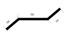
- FIG. 1 is an example of a linear breaking rib used in the separator for a lead storage battery of the present invention, which has two or more bending points and bends to the opposite side at two consecutive bending points.
- the linear fracture rib shown in FIG. 1 has two bending points, and in this case, (a), (b), and (c) each represent a line segment of the linear fracture rib.
- As the linear breaking rib having two or more bending points and bending to the opposite side at two consecutive bending points for example, a line segment (a) having two rotational symmetry.
- the angle of the internal angle formed by the line segment (b) (bending angle) is the same as the angle of the internal angle formed by the line segment (b) and the line segment (c) (bending angle), and the line segment (a) and the line segment are formed.
- Those having the same length in (c) are preferably used, but the angle (bending angle) of the internal angle formed by the line segment (a) and the line segment (b), and the line segment (b) and the line segment (c) are used.
- a line segment located at both ends for example, a line segment (a).
- the line segment (c) are substantially parallel to each other, that is, the angle (bending angle) of the internal angle formed by the linear segment (a) and the linear segment (b), and the angle of the internal angle formed by the linear segment (b) and the linear segment (c).
- the difference in (bending angle) is preferably within 10 degrees, more preferably within 5 degrees.
- the bending angle (internal angle angle) at all the bending points is set.
- Those having a temperature of 90 degrees or more and smaller than 180 degrees are preferable, and those having a temperature of 120 degrees or more and 150 degrees or less are more preferable. Further, those having an even number of bending points are preferable, and those having two bending points are more preferable.
- the line segment in the curved breaking rib having one or more inflection points used in the separator for a lead storage battery of the present invention is a line segment of an adjacent extreme value point and an extreme value point in the curved breaking rib. It means between, and between the end of the break rib and the adjacent extremum point.
- the curved breaking rib having one or more turning points has two rotational symmetry, for example, in the case of a curved breaking rib having one turning point, two adjacent poles.
- radius of curvature at one pole may be different, or the lengths of two line segments located between the ends of the two breaking ribs and the adjacent poles may be different.
- the curved breaking rib having one or more turning points is the angle of the internal angle formed by the tangent line at the turning point and the tangent line at the adjacent turning point, or the tangent line and the rib at the turning point.
- the angle of the internal angle formed by the tangent at the tip portion is preferably 90 degrees or more and smaller than 180 degrees, and more preferably 120 degrees or more and 150 degrees or less. Further, it is preferable to have an inflection point, and it is more preferable to have one inflection point.
- the angle of the internal angle formed by the tangent line at the inflection point and the tangent line at the rib tip portion is 90 degrees or more and 180 degrees. Smaller ones are preferable, and those having 120 degrees or more and 150 degrees or less are more preferable.
- the breaking rib used in the separator for a lead storage battery of the present invention has a total length (for example, in the linear breaking rib shown in FIG. 1, the lengths of the line segment (a), the line segment (b), and the line segment (c)).
- the total sum) is preferably 5 to 40 mm
- the height is preferably 0.05 to 1.20 mm
- the width is preferably 0.5 to 2.0 mm (preferably 0.5 mm to 1.0 mm).
- the vertical cross-sectional shape of the broken rib is square, trapezoidal, semicircular, rectangular with a dome-shaped top surface, trapezoidal shape with a dome-shaped top surface, and a trapezoidal shape with curved sides in the height direction.
- It is preferable that the corners of the top surface are chamfered in a rectangular shape or an isosceles triangle shape.
- sulfuric acid having a high specific density generated in the positive electrode plate during charging settles to the bottom (lower side) of the battery due to the difference in specific gravity, and causes stratification of the electrolytic solution.
- the lead-acid battery separator of the present invention by arranging a broken rib having a specific shape on the surface on the side in contact with the positive electrode plate, the movement of sulfuric acid having a high specific density generated during charging to the bottom (lower) of the battery is hindered. Therefore, the stratification of the electrolytic solution can be suppressed.
- Sulfuric acid with a high specific density generated in the positive electrode plate is settled to the bottom (lower side) of the battery along the surface of the separator on the side in contact with the positive electrode plate. At this time, the movement of sulfuric acid to the bottom (downward) of the battery is hindered by the breaking rib having the specific shape arranged on the surface on the side in contact with the positive electrode plate.
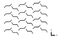
- Breaking ribs with a specific shape are arranged. That is, as in the arrangement example of the breaking ribs shown in FIGS. 2 to 5, in the lead storage battery separator of the present invention, the breaking ribs are arranged substantially horizontally with respect to the horizontal direction (CD direction) of the separator. , The movement of sulfuric acid to the bottom (downward) of the battery is hindered.
- the breaking ribs are arranged substantially horizontally with respect to the horizontal direction (CD direction) of the separator. .
- the movement of sulfuric acid to the bottom (downward) of the battery is hindered.
- the line segment (b), or the line segment (a) and / or the line segment (c) is within 90 degrees with respect to the horizontal direction (CD direction) of the separator. It is preferable that they are arranged at an inclination of 60 degrees or less, and more preferably they are arranged at an inclination of 60 degrees or less. Further, for example, in the case of a curved breaking rib having one inflection point, it is preferable that the tangent line at the inflection point is arranged with an inclination of 45 degrees or less with respect to the horizontal direction (CD direction) of the separator. It is more preferably arranged with an inclination of 30 degrees or less, and further preferably arranged with an inclination of 10 degrees or less.
- the break ribs generated during charging are prevented from moving linearly downward by the break ribs on which sulfuric acid is arranged, and the breaks adjacent to each other in the vertical direction (MD direction) of the separator so as to move downward in a zigzag manner. It is preferable that the ribs are arranged so that they do not completely overlap each other when viewed from the vertical direction (MD direction) of the separator.
- sulfuric acid generated during charging passes between the breaking rib and another breaking rib adjacent to the breaking rib in the horizontal direction (CD direction) of the separator, and the battery is used.
- a set of breaking ribs and breaking ribs adjacent to each other in the horizontal direction (CD direction) of the separator so as not to move downward linearly (parallel to the vertical direction of the separator) from the top to the bottom of the battery.
- the overlap with the formed gap from the vertical direction (MD direction) of the separator is preferably less than 50%, more preferably less than 20%, and even more preferably 0%.
- the gap formed between the set of breaking ribs adjacent to each other in the horizontal direction (CD direction) of the separator is as shown in the arrangement example of the breaking ribs in FIGS. 3 to 5.
- a gap formed between a set of adjacent breaking ribs arranged on the left side of the uppermost portion and the breaking ribs, and a gap downward in the vertical direction (MD direction) of the separator is preferably less than 50%, more preferably less than 20%, and even more preferably 0%.
- the gap formed between the set of breaking ribs adjacent to each other in the horizontal direction (CD direction) of the separator is as shown in the arrangement example of the breaking ribs in FIGS. 3 to 5.
- the gap formed between a set of adjacent breaking ribs arranged adjacently on the left side of the second row from the top and the breaking ribs is viewed from the vertical direction (MD direction) of the separator. There is no overlap (0% overlap).
- the breaking ribs shown in FIG. 2 for example, the breaking ribs arranged first from the top in the third row from the left and the breaking ribs arranged first from the top in the second row from the left. It is arranged first from the top in the second row from the left, which is a gap formed between the broken ribs and the gaps arranged adjacent to each other in the vertical direction (MD direction) of the separator.
- the gap formed between the breaking ribs and the breaking ribs arranged second from the top in the third row from the left does not overlap when viewed from the vertical direction (MD direction) of the separator. Not possible (0% overlap).
- the above-mentioned relationship (the gap formed between a set of adjacent breaking ribs and the breaking ribs and the separator is arranged adjacent to the bottom in the vertical direction (MD direction).
- the total amount of the broken ribs arranged on the surface of the separator on the side in contact with the positive electrode plate is preferably 50% or more.
- the breaking rib and the breaking rib in the horizontal direction (CD direction), and is closest to the breaking rib. It is located on the right side of the gap formed between the breaking rib and another breaking rib arranged adjacent to the breaking rib and the breaking rib and the separator of the breaking rib in the horizontal direction (CD direction).
- the overlap of the gap formed between the breaking rib and another breaking rib placed adjacent to the second closeness from the vertical direction (MD direction) of the separator is less than 50%. Is more preferable, less than 20% is more preferable, and 0% is even more preferable.
- the fracture rib and another fracture rib located on the right side of the separator of the fracture rib in the horizontal direction (CD direction) and located adjacent to the fracture rib closest to the fracture rib.
- the gap formed between the fracture ribs is, for example, the fracture ribs arranged second from the top in the second row from the left and the separator of the fracture ribs in the horizontal direction (in the example of arrangement of the fracture ribs in FIG. 2).
- the gap formed between the rib and the breaking rib (the shortest distance between the end of the breaking rib and another breaking rib adjacent to the rib).
- another breaking rib located on the right side of the breaking rib and the separator of the breaking rib in the horizontal direction (CD direction) and adjacent to the breaking rib and the second closest to the breaking rib.
- the gap formed between the fracture ribs is, for example, the fracture ribs arranged second from the top in the second row from the left in the arrangement example of the fracture ribs in FIG. 2, and the horizontal separator of the fracture ribs.
- the gap formed between the fractured ribs arranged (the shortest distance between the fractured ribs and the end of another fractured rib adjacent to the fractured ribs).
- the two gaps do not overlap when viewed from the vertical direction (MD direction) of the separator (overlap 0%).
- MD direction vertical direction
- CD direction horizontal direction
- it is located on the left side of the breaking rib and the breaking rib in the horizontal direction (CD direction) of the breaking rib and the most. It is located on the left side of the gap formed between another fractured rib located adjacent to each other and the fractured rib and the separator of the fractured rib in the horizontal direction (CD direction).
- the overlap of the gap formed between the breaking rib and another breaking rib arranged adjacent to the second closeness from the vertical direction (MD direction) of the separator is less than 50%. It is preferably less than 20%, more preferably 0%.
- the fracture rib and another fracture rib located on the left side of the separator of the fracture rib in the horizontal direction (CD direction) and located adjacent to the fracture rib closest to the fracture rib.
- the gap formed between the fracture ribs is, for example, the fracture ribs arranged third from the top in the second row from the right and the separator of the fracture ribs in the horizontal direction (in the example of arrangement of the fracture ribs in FIG. 2).
- Another breaking rib located on the left side of the direction (CD direction) and adjacent to the breaking rib second close to it, i.e., third from the top in the third row from the right. It means the gap formed between the fractured ribs arranged (the shortest distance between the end of the fractured rib and another adjacent fractured rib). In the example of arrangement of the breaking ribs in FIG. 2, the two gaps do not overlap when viewed from the vertical direction (MD direction) of the separator (overlap 0%).
- the fracture rib shown in the arrangement example of the fracture rib in FIG. 2 is a linear fracture rib having two bending points, and the line segments located at both ends are substantially parallel to each other, and the bending at all the bending points. It has a shape with an angle of 90 degrees or more and smaller than 180 degrees.
- the line segments (b) (see FIG. 1) of the breaking ribs are arranged so as to be substantially horizontal to each other with respect to the horizontal direction (CD direction) of the separator. Further, unless it is located at the top or bottom of the separator, it is located on the right side of the breaking rib and the breaking rib in the horizontal direction (CD direction) of the breaking rib and the most.
- the sulfuric acid that has moved along the shape of the breaking rib is transferred from the lower end end portion (the gap formed between the adjacent set of breaking ribs) in the vertical direction (MD direction) of the breaking rib separator to the battery.
- MD direction vertical direction
- another breaking rib arranged below the separator in the vertical direction (MD direction) hinders the linear downward movement of the breaking rib. Move along the shape.
- the sulfuric acid generated in the positive electrode plate is hindered from moving downward linearly from the top of the battery to the bottom of the battery, and moves downward in a zigzag manner due to the arranged breaking ribs and their shapes. It is considered that stratification can be made difficult to occur.
- the breaking rib shown in the arrangement example of the breaking rib in FIG. 3 is a linear breaking rib having two bending points, the line segments located at both ends are parallel to each other, and the bending angles at all the bending points. Has a shape of 90 degrees or more and smaller than 180 degrees. Then, the line segments (a) and the line segments (c) (see FIG. 1) of the breaking ribs are arranged so as to be horizontal to each other with respect to the horizontal direction (CD direction) of the separator. Further, a gap formed between a set of breaking ribs adjacent to each other in the horizontal direction (CD direction) of the separator and a separator arranged adjacent to the vertical direction (MD direction) of the separator.
- the fracture rib shown in the arrangement example of the fracture rib in FIG. 4 is a linear fracture rib having two bending points, the line segments located at both ends are parallel to each other, and the bending angles at all the bending points. Has a shape of 90 degrees.
- the line segments (b) (see FIG. 1) of the breaking ribs are arranged so as to be horizontal to each other with respect to the horizontal direction (CD direction) of the separator. Further, a gap formed between a set of breaking ribs adjacent to each other in the horizontal direction (CD direction) of the separator and a separator arranged adjacent to the vertical direction (MD direction) of the separator.
- the breaking rib shown in the arrangement example of the breaking rib in FIG. 5 is a curved breaking rib having one inflection point, and the angle of the internal angle formed by the tangent line at the inflection point and the tangent line at the rib tip portion is 90 degrees or more. It has a shape smaller than 180 degrees.
- the tangents at the inflection points of the breaking ribs are arranged so as to be substantially horizontal to each other with respect to the horizontal direction (CD direction) of the separator. Further, a gap formed between a set of breaking ribs adjacent to each other in the horizontal direction (CD direction) of the separator and a separator arranged adjacent to the vertical direction (MD direction) of the separator.
- the number of breaking ribs is 4 to 20 in the horizontal direction (CD direction) of the separator and in the vertical direction (MD direction) of the separator. It is preferable to arrange 10 to 20 pieces, and more preferably 5 to 10 pieces in the horizontal direction (CD direction) of the separator and 10 to 15 pieces in the vertical direction (MD direction) of the separator.
- the thickness of the separator is preferably 0.1 to 0.3 mm, excluding the height of the rib, and is 0.15 mm or more and 0.25 mm or less. It is more preferable to have. If the base thickness becomes too thick, the internal resistance of the lead-acid battery becomes high, which is not desirable as a lead-acid battery for an idling stop vehicle. On the other hand, if it is less than 0.15 mm, the strength of the separator is lowered, and the separator may be torn during vibration, which is not preferable. Further, it is preferable that the total thickness of the separator including the ribs on both sides is 1.4 mm or less.
- the porosity of the separator is preferably 50 to 90% by volume.
- the internal resistance electrical resistance
- the porosity of the separator is more preferably 60 to 90% by volume, more preferably 70 to 90% by volume.
- the breaking rib is made of the same material as the separator base portion which is the flat plate portion of the separator and is integrally molded together with the base portion.
- the separator can be advantageous in terms of productivity and manufacturing cost.
- the separator for a lead storage battery of the present invention is not particularly limited in terms of constituent materials, manufacturing method, etc., but for example, a raw material composition containing an appropriate amount of a thermoplastic resin, an inorganic powder, and a plasticizer is extruded in a biaxial manner. After being extruded into a sheet while being heated, melted and kneaded by a machine or the like, and formed into a sheet having a predetermined thickness and a predetermined shape through a pair of molding rolls in which a predetermined groove is pre-engraved so as to give a predetermined rib shape, the sheet is formed. Any product may be obtained by immersing in an appropriate solvent compatible with the plasticizer, extracting and removing a predetermined amount of the plasticizer, and drying.
- thermoplastic resin used in the separator for a lead storage battery of the present invention examples include polyvinyl chloride resins such as polyvinyl chloride (PVC); and polyolefin resins such as polyethylene, polypropylene and ethylene-butene copolymers.
- a polyolefin resin is preferably used, more preferably a polyethylene resin, and even more preferably a high molecular weight polyethylene resin.
- the high molecular weight polyethylene resin preferably has a molecular weight of at least 600,000, and more preferably an ultra high molecular weight polyethylene resin (UHMWPE) having a molecular weight of 5 million.
- UHMWPE ultra high molecular weight polyethylene resin
- Examples of the inorganic powder used in the separator for a lead storage battery of the present invention include silica such as precipitated silica and fumed silica, mica, montmorillonite, kaolinite, talc, silicate soil, vermiculite, natural and synthetic zeolite, calcium silicate, and clay.
- silica such as precipitated silica and fumed silica
- mica montmorillonite
- kaolinite kaolinite
- talc silicate soil
- vermiculite vermiculite
- natural and synthetic zeolite calcium silicate, and clay.
- silica such as precipitated silica and fumed silica is preferably used.
- the plasticizer used for the separator for a lead storage battery of the present invention it is preferable to select a material that can be a plasticizer for the polyolefin resin, and various organic substances that are compatible with the polyolefin resin and can be easily extracted with various solvents or the like.
- Liquid material can be used.
- mineral oils such as industrial lubricating oils made of saturated hydrocarbons (paraffin), higher alcohols such as stearyl alcohol, and ester plasticizers such as dioctyl phthalate can be used. Of these, mineral oil is preferable because it is easy to reuse.
- the plasticizer is preferably blended in the raw material composition in an amount of 30 to 70% by weight.
- a saturated hydrocarbon-based organic solvent such as hexane, heptane, octane, nonane, and decane can be used.
- antioxidants for the raw material composition or the separator after film formation, if necessary, antioxidants, UV absorbers, weather resistant agents, lubricants, antibacterial agents, fungicides, pigments, dyes, colorants, antifogging agents, matting agents.
- Additives such as agents may be added (blended) or contained within a range that does not impair the object and effect of the present invention.
- the lead storage battery of the present invention is not limited to the following embodiments.
- the electrolytic solution contains sulfuric acid in the aqueous solution.
- the electrolytic solution may be gelled if necessary.
- the electrolytic solution can contain additives used in lead-acid batteries, if necessary.
- the specific gravity of the electrolytic solution in a fully charged lead-acid battery after chemical conversion at 20 ° C. is, for example, 1.10 g / cm 3 or more and 1.35 g / cm 3 or less.
- the paste type positive electrode plate includes a positive electrode current collector and a positive electrode material.
- the positive electrode material is held in the positive current collector.
- the positive electrode material is the positive electrode plate minus the positive electrode current collector.
- the positive electrode current collector may be formed in the same manner as the negative electrode current collector, and can be formed by casting lead or a lead alloy or processing a lead or a lead alloy sheet.
- the clad type positive electrode plate has a plurality of porous tubes, a core metal inserted in each tube, a positive electrode material filled in the tube into which the core metal is inserted, and a collective punishment for connecting multiple tubes. Equipped with.
- the positive electrode material is the positive electrode plate excluding the tube, the core metal, and the collective punishment.
- the positive electrode current collector may have lead alloy layers having different compositions, and may have a plurality of alloy layers. It is preferable to use a Pb—Ca alloy or a Pb—Sb alloy for the core metal.
- the positive electrode material contains a positive electrode active material (lead dioxide or lead sulfate) that develops a capacity by a redox reaction.
- the positive electrode material may contain other additives, if necessary.
- the unchemical paste type positive electrode plate can be obtained by filling a positive electrode current collector with a positive electrode paste, aging and drying, as in the case of a negative electrode plate. After that, an unchemical positive electrode plate is formed.
- the positive electrode paste is prepared by kneading lead powder, additives, water and sulfuric acid.
- the clad type positive electrode plate is formed by filling a tube into which a core metal is inserted with lead powder or slurry-like lead powder, and connecting a plurality of tubes in a collective punishment.
- the negative electrode plate of a lead storage battery is composed of a negative electrode current collector and a negative electrode material.
- the negative electrode electrode material is obtained by removing the negative electrode current collector from the negative electrode plate.
- the negative electrode current collector may be formed by casting lead (Pb) or a lead alloy, or may be formed by processing a lead or lead alloy sheet. Examples of the processing method include expanding processing and punching processing. It is preferable to use a negative electrode grid as the negative electrode current collector because it is easy to support the negative electrode material.
- the lead alloy used for the negative electrode current collector may be any of Pb—Sb-based alloys, Pb-Ca-based alloys, and Pb-Ca—Sn-based alloys. These leads or lead alloys may further contain, as an additive element, at least one selected from the group consisting of Ba, Ag, Al, Bi, As, Se, Cu and the like.
- the negative electrode material contains a negative electrode active material (lead or lead sulfate) that develops capacity by a redox reaction, and may contain a shrink-proofing agent, a carbonaceous material such as carbon black, barium sulfate, or the like, if necessary. And may contain other additives.
- the negative electrode active material in the charged state is spongy lead, but the unchemical negative electrode plate is usually produced using lead powder.
- the negative electrode plate can be formed by filling a negative electrode current collector with a negative electrode paste, aging and drying to produce an unchemical negative electrode plate, and then forming an unchemical negative electrode plate.
- the negative electrode paste can be prepared by adding water and sulfuric acid to lead powder, an organic shrink-proofing agent and, if necessary, various additives, and kneading them. In the aging step, it is preferable to ripen the unchemical negative electrode plate at a temperature higher than room temperature and high humidity.
- Chemical formation can be performed by charging the electrode plate group in a state where the electrode plate group including the unchemical negative electrode plate is immersed in the electrolytic solution containing sulfuric acid in the electric tank of the lead storage battery. However, the chemical conversion may be performed before assembling the lead-acid battery or the electrode plate group. The formation produces spongy lead.
- Example 1 Preparation of Microporous Film Separator (Example 1) 30 parts by mass of ultra-high molecular weight polyethylene resin (UHMWPE) powder with an average molecular weight of 5 million as a thermoplastic resin, 70 parts by mass of fine silica powder with an average particle size of 15 ⁇ m as an inorganic powder, and one kind of mineral oil as a plasticizer. A paraffinic oil was mixed with a mixer. The obtained mixture is heated, melted and kneaded by a twin-screw extruder and extruded into a sheet shape from a T-die, and pressed through a pair of forming rolls composed of rolls having grooves corresponding to rib patterns on both sides of the sheet. Molded.
- UHMWPE ultra-high molecular weight polyethylene resin
- the main rib for contacting the positive electrode plate having a predetermined shape is on one surface of the sheet, and the negative electrode having a linear continuous shape parallel to the flow direction (Machine Direction: MD direction) of extrusion molding on the opposite surface.
- MD direction Machine Direction
- a non-porous film in which the mini ribs for abutting were integrally molded was produced. Then, a continuous non-porous film was passed through a liquid tank containing an organic solvent so as to be immersed in the liquid tank, and the paraffinic oil was extracted and removed leaving a part thereof. By passing this film through the drying oven, a microporous film separator having a total thickness of 0.70 mm and a base portion thickness of 0.20 mm was produced.
- the breaking rib for contacting the positive electrode has a linear breaking rib shape having two bending points as shown in FIG. 1, and each side of each breaking rib, a line segment (a). ,
- the length and angle of the line segment (b) and the line segment (c) are such that the length of the line segment (a) and the line segment (c) is 4.5 mm, and the length of the line segment (b) is 10 mm.
- the angle at which each of the line segment (a) and the line segment (c) forms with the line segment (b) is 135 degrees, and the line segment (b) is parallel to the horizontal direction (CD direction) of the separator. As shown in FIG.
- each breaking rib is arranged substantially horizontally, and the adjacent breaking ribs in the horizontal direction (CD direction) of the separator are aligned with respect to the axis parallel to the vertical direction (MD direction) of the separator.
- the relationship is like mirror image symmetry.
- the gap between the breaking ribs adjacent to each other in the horizontal direction (CD direction) of these separators and the closest to each other in the vertical direction (MD direction) of the separator in the horizontal direction (CD direction) of the separator in the horizontal direction (CD direction) of the separator.
- the gap between the adjacent breaking ribs (for example, in FIG. 2, the breaking rib arranged second from the top in the leftmost column and the breaking rib arranged second from the top in the second row from the left).
- the gap between them and the gap between the break ribs placed second from the top in the leftmost column and the break ribs placed first from the top in the second row from the left) are separators. When viewed from the vertical direction (MD direction) of, they do not overlap each other at all, and their gaps are all 3 mm.
- the breaking rib for positive electrode contact has a trapezoidal cross section perpendicular to the longitudinal direction of the rib, the height of the rib is 0.40 mm, the lower side width of the trapezoidal cross section of the rib is 0.80 mm, and the upper side. The width is 0.40 mm.
- the mini-rib for contacting the negative electrode has a rectangular cross-sectional shape perpendicular to the longitudinal direction of the mini-rib. The height of the mini ribs is 0.10 mm, the distance between the mini ribs is 0.55 mm, and the width of the mini ribs is 0.10 mm.
- Example 2 A microporous film separator similar to that in Example 1 was produced except that the length of the line segment (b) of the breaking rib for contacting the positive electrode was set to 7 mm.
- Comparative Example 1 The ribs for contacting the positive electrode were linearly continuous ribs in the vertical direction (MD direction) of the separator, and a microporous film separator similar to that in Example 1 was produced except that the width between the ribs was 10 mm.
- the rib for contacting the positive electrode is composed of a linear breaking rib having a length of 12 mm having no bending point, has an inclination of 75 degrees with respect to the horizontal direction (CD direction) of the separator, and is a separator. Two sets are arranged at equal intervals of 12 mm in the horizontal direction (CD direction), the arrangement (arrangement 1) arranged in the vertical direction (MD direction) of the separator, and the horizontal direction (CD direction) of the separator.
- Two sets of separators with an inclination of 105 degrees and arranged at equal intervals of 12 mm in the horizontal direction (CD direction) of the separator, and an array (array 2) arranged in the vertical direction (MD direction) of the separator are with array 1.
- a microporous film separator similar to that of Example 1 was prepared except that the arrangement 2 was arranged alternately in the vertical direction (MD direction) of the separator without any gap.
- the rib for contacting the positive electrode is composed of two types of linear breaking ribs (breaking rib A and breaking rib B) having a length of 25 mm and having no bending point, and the breaking rib A is a separator. It has an inclination of 45 degrees with respect to the horizontal direction (CD direction), is arranged at equal intervals of 30 mm in the horizontal direction (CD direction) and the vertical direction (MD direction) of the separator, and the breaking ribs B are arranged in the horizontal direction of the separator.
- a cell in which a microporous film separator is sandwiched between two acrylic plates is referred to as a cell.
- the bolt tightening was adjusted so that the gap between the acrylic plates of the cell was 0.65 mm.
- the prepared cell was placed in a water tank filled with water up to a height of 115 mm.
- the ribs for contacting the positive electrode are arranged linearly and continuously in the vertical direction (MD direction) of the separator, and the space between the positive electrode and the separator is relative to the vertical direction (MD direction) of the separator. Since the sections are separated by long sections, it is difficult for the electrolytic solution to flow between the sections corresponding to the horizontal direction (CD direction) of the separator. Therefore, the dropped colored sodium chloride aqueous solution settled in the region vertically separated by the ribs in the vertical direction (MD direction) of the separator, and reached the lower end of the separator 7 seconds later.
- the horizontal diffusion (CD direction) of the colored sodium chloride aqueous solution of the separator was limited to the range of 10 mm in width separated by the ribs for abutting the positive electrode.
- the diffusion effect of the separator in the horizontal direction (CD direction) is low, and it is used for positive electrode contact arranged in the vertical direction (MD direction) of the separator. Since the downward movement along the rib is fast, the shape is such that the stratification of the electrolytic solution is likely to occur.
- the ribs for contacting the positive electrode of Comparative Example 2 are linear breaking ribs arranged in the vertical direction (MD direction) of the separator, and are separated by long sections with respect to the vertical direction (MD direction) of the separator. Not done.
- the dropped colored sodium chloride aqueous solution spread 45 mm in the horizontal direction (CD direction) of the separator due to the inclined breaking rib, but reached the lower end of the separator after 5 seconds.
- the gap formed between the breaking ribs adjacent to each other in the horizontal direction (CD direction) of the separator is above and below the separator. Since they overlap in the direction (MD direction), the colored sodium chloride aqueous solution is linearly settled in the vertical direction (MD direction) of the separator, and the shape is such that stratification of the electrolytic solution is relatively easy to occur.
- Comparative Example 4 the time required for the colored sodium chloride aqueous solution to settle is shorter than in Examples 1 and 2.
- the shape of the breaking rib of Comparative Example 4 is a linear shape having a bending point, but the gap formed between the breaking ribs adjacent to each other in the horizontal direction (CD direction) of the separator is the vertical direction of the separator (the breaking rib). Since they are completely overlapped in the MD direction), the effect of suppressing the stratification of the electrolytic solution is smaller than that of Examples 1 and 2.
- the dropped colored sodium chloride aqueous solution sufficiently spreads in the horizontal direction (CD direction) of the separator, settles in the vertical direction (MD direction) of the separator, and reaches the lower end of the separator. It took 16 seconds and 17 seconds, respectively.
- the range (diffusion range) in which the liquid separator spreads in the horizontal direction (CD direction) is wide, and the sedimentation time in the vertical direction (MD direction) of the separator is also long. The effect of suppressing is great.
- the separator for a lead storage battery of the present invention has the shape of a breaking rib effective for controlling the movement of the electrolytic solution inside the electric tank, and the breaking rib can effectively control the movement of the electrolytic solution inside the electric tank. Since it is arranged in, it is possible to suppress the stratification of the electrolytic solution, and to provide an optimum separator capable of suppressing the decrease in the reliability of battery control and the decrease in the battery life due to the stratification of the electrolytic solution. Was done.
Landscapes
- Chemical & Material Sciences (AREA)
- Chemical Kinetics & Catalysis (AREA)
- Electrochemistry (AREA)
- General Chemical & Material Sciences (AREA)
- Engineering & Computer Science (AREA)
- Manufacturing & Machinery (AREA)
- Cell Separators (AREA)
- Secondary Cells (AREA)
Abstract
Description
(1)液式鉛蓄電池に用いられる鉛蓄電池用セパレータであって、多孔質バックウェブ及び前記バックウェブの両面それぞれから延びている複数のリブとから成り、正極極板に接触する側の面にあるリブが破断リブであって、該形状が、2か所以上の屈曲点を有し、連続する2つの屈曲点でそれぞれ逆側に屈曲する直線状の破断リブ、または1か所以上の変曲点を有する曲線状の破断リブであることを特徴とする鉛蓄電池用セパレータ。
(2)前記破断リブが、屈曲角度が互いに異なるもの、または線分の長さが互いに異なるものが含まれることを特徴とする上記(1)記載の鉛蓄電池用セパレータ。
(3)前記破断リブが、2回の回転対称性を有することを特徴とする上記(1)記載の鉛蓄電池用セパレータ。
(4)前記破断リブが、両端に位置する線分どうしが互いに略平行な直線状の破断リブであることを特徴とする上記(1)記載の鉛蓄電池用セパレータ。
(5)前記破断リブが、すべての屈曲点における屈曲角度が90度以上、180度より小さい形状を有する直線状の破断リブであることを特徴とする上記(1)~(4)のいずれかに記載の鉛蓄電池用セパレータ。
(6)前記破断リブが、屈曲点を2つ有する直線状の破断リブであることを特徴とする上記(1)~(5)のいずれかに記載の鉛蓄電池用セパレータ。
(7)前記破断リブが、変曲点における接線と隣接する変曲点における接線がなす内角の角度、もしくは変曲点における接線とリブ先端部分における接線がなす内角の角度が90度以上、180度より小さい形状を有する曲線状の破断リブであることを特徴とする上記(1)~(3)のいずれかに記載の鉛蓄電池用セパレータ。
(8)前記破断リブが、変曲点を1つ有し、変曲点における接線とリブ先端部分における接線がなす内角の角度が90度以上、180度より小さい形状を有する曲線状の破断リブであることを特徴とする上記(7)記載の鉛蓄電池用セパレータ。
(9)複数の前記破断リブが、セパレータの水平方向(CD方向)に対して、互いに略水平に配置されていることを特徴とする上記(1)~(8)のいずれかに記載の鉛蓄電池用セパレータ。
(10)複数の前記破断リブが、前記破断リブと、セパレータの上下方向(MD方向)において該破断リブと隣接する他の前記破断リブとが、セパレータの上下方向(MD方向)において完全に重りあうことのないように配置されていることを特徴とする上記(1)~(8)のいずれかに記載の鉛蓄電池用セパレータ。
(11)複数の前記破断リブが、セパレータの水平方向(CD方向)において互いに隣接する1組の前記破断リブと前記破断リブとの間に形成される隙間が、セパレータの上下方向(MD方向)に隣接して配置される、セパレータの水平方向(CD方向)において互いに隣接する他の1組の前記破断リブと前記破断リブとの間に形成される隙間と、セパレータの上下方向(MD方向)において完全に重りあうことのないように配置されていることを特徴とする上記(1)~(8)のいずれかに記載の鉛蓄電池用セパレータ。
(12)複数の前記破断リブが、前記破断リブとセパレータの水平方向(CD方向)に対して右側に位置し、該破断リブと最も近くに隣接する前記破断リブとの間に形成される隙間が、該破断リブのセパレータの水平方向(CD方向)に対して右側に位置し、該破断リブと2番目の近さに隣接する前記破断リブとの間に形成される隙間と、セパレータの上下方向(MD方向)において重りあうことのないように配置されているか、または、前記破断リブとセパレータの水平方向(CD方向)に対して左側に位置し、該破断リブと最も近くに隣接する前記破断リブとの間に形成される隙間が、該破断リブのセパレータの水平方向(CD方向)に対して左側に位置し、該破断リブと2番目の近さに隣接する前記破断リブとの間に形成される隙間と、セパレータの上下方向(MD方向)において重りあうことのないように配置されていることを特徴とする上記(1)~(8)のいずれかに記載の鉛蓄電池用セパレータ。
(13)上記(1)~(12)のいずれかに記載のセパレータを使用したことを特徴とする鉛蓄電池。
図1に示す直線状の破断リブは、屈曲点を2か所有しており、この場合の、(a)、(b)、(c)は、それぞれ直線状の破断リブの線分を表す。
前記2か所以上の屈曲点を有し、連続する2つの屈曲点でそれぞれ逆側に屈曲する直線状の破断リブとしては、2回の回転対称性を有するもの、例えば線分(a)と線分(b)がなす内角の角度(屈曲角度)と、線分(b)と線分(c)がなす内角の角度(屈曲角度)が同じであって、線分(a)と線分(c)の長さが同じであるもの、が好ましく用いられるが、線分(a)と線分(b)がなす内角の角度(屈曲角度)と、線分(b)と線分(c)がなす内角の角度(屈曲角度)が異なるもの、または線分(a)と線分(c)の長さが異なるものであってもよい。
また、偶数の屈曲点を有するものが好ましく、屈曲点を2つ有するものがより好ましい。
前記1か所以上の変曲点を有する曲線状の破断リブとしては、2回の回転対称性を有するもの、例えば変曲点を1つ有する曲線状の破断リブの場合、隣接する2つの極値点における曲率半径が同じであって、2つの破断リブ末端と隣接する極値点との間に位置する2つの線分の長さが同じであるもの、が好ましく用いられるが、隣接する2つの極値点における曲率半径が異なるもの、または2つの破断リブ末端と隣接する極値点との間に位置する2つの線分の長さが異なるものであってもよい。
また、奇数の変曲点を有することが好ましく、変曲点を1つ有することがより好ましく、変曲点における接線とリブ先端部分における接線がなす内角の角度が90度以上であって180度より小さいものが好ましく、120度以上であって150度以下であるものがより好ましい。
本発明の鉛蓄電池用セパレータは、特定の形状を有する破断リブを正極極板に接触する側の面に配置することによって、充電時に生じる高比重の硫酸の電池底部(下方)への移動を阻害して、電解液の成層化を抑制することができるものである。
すなわち、図2~5に示される破断リブの配置例のように、本発明の鉛蓄電池用セパレータでは、セパレータの水平方向(CD方向)に対して、互いに略水平に破断リブを配置することによって、硫酸の電池底部(下方)への移動が阻害される。
例えば、図1に示される直線状の破断リブの場合、線分(b)、もしくは線分(a)および/または線分(c)がセパレータの水平方向(CD方向)に対して90度以内の傾きで配置されていることが好ましく、60度以内の傾きで配置されていることがより好ましい。
また、例えば、変曲点を1つ有する曲線状の破断リブの場合、変曲点における接線がセパレータの水平方向(CD方向)に対して45度以内の傾きで配置されていることが好ましく、30度以内の傾きで配置されていることがより好ましく、10度以内の傾きで配置されていることがさらに好ましい。
この場合の、セパレータの水平方向(CD方向)において互いに隣接する1組の破断リブと破断リブとの間に形成される隙間とは、図3~5の破断リブの配置例に示されるような、セパレータの水平方向(CD方向)対して略平行に配置されている1組の隣接する破断リブと破断リブとの間に形成される隙間をいう。
例えば、図4の破断リブの配置例において最上部左側に配置されている1組の隣接する破断リブと破断リブとの間に形成される隙間と、セパレータの上下方向(MD方向)において下に隣接して配置されている、上から2列目左側に配置されている1組の隣接する破断リブと破断リブとの間に形成される隙間とは、セパレータの上下方向(MD方向)から見て、重なりは見られない(重なり0%)。
図3および図5に示される破断リブの配置例においても同様である。
また、図2に示される破断リブの配置例の場合では、例えば、左から3番目の列の上から1番目に配置されている破断リブと、左から2列目の上から1番目に配置されている破断リブとの間に形成される隙間と、セパレータの上下方向(MD方向)において下に隣接して配置されている隙間である、左から2列目の上から1番目に配置されている破断リブと、左から3番目の列の上から2番目に配置されている破断リブとの間に形成される隙間とは、セパレータの上下方向(MD方向)から見て、重なりは見られない(重なり0%)。
本発明の鉛蓄電池用セパレータにおいて、上記の関係(1組の隣接する破断リブと破断リブとの間に形成される隙間と、セパレータの上下方向(MD方向)において下に隣接して配置されている、別の1組の隣接する破断リブと破断リブとの間に形成される隙間との、セパレータの上下方向(MD方向)から見た重なり具合)を維持しながら配置されている破断リブが、セパレータの正極極板に接触する側の面に配置されている破断リブ全体で、50%以上であることが好ましい。
この場合において、破断リブと、該破断リブのセパレータの水平方向(CD方向)に対して向かって右側に位置し、該破断リブと最も近くに隣接して配置されている別の破断リブとの間に形成される隙間とは、例えば、図2の破断リブの配置例において、左から2番目の列の上から2番目に配置されている破断リブと、該破断リブのセパレータの水平方向(CD方向)に対して向かって右側に位置し、該破断リブと最も近くに隣接して配置されている別の破断リブ、すなわち、左から3列目の上から3番目に配置されている破断リブとの間に形成される隙間(該破断リブの端部と隣接する別の破断リブとの間の最短距離)を意味する。
また、該破断リブと、該破断リブのセパレータの水平方向(CD方向)に対して向かって右側に位置し、該破断リブと2番目の近さに隣接して配置されている別の破断リブとの間に形成される隙間とは、例えば、図2の破断リブの配置例において、左から2番目の列の上から2番目に配置されている破断リブと、該破断リブのセパレータの水平方向(CD方向)に対して向かって右側に位置し、該破断リブと2番目の近さに隣接して配置されている別の破断リブ、すなわち、左から3列目の上から2番目に配置されている破断リブとの間に形成される隙間(該破断リブと隣接する別の破断リブの端部との間の最短距離)を意味する。
そして、図2の破断リブの配置例においては、この2つの隙間は、セパレータの上下方向(MD方向)から見た場合に、重なりは見られない(重なり0%)。
同様に、セパレータの最上部もしくは最下部に配置されている場合を除き、破断リブと、該破断リブのセパレータの水平方向(CD方向)に対して向かって左側に位置し、該破断リブと最も近くに隣接して配置されている別の破断リブとの間に形成される隙間と、該破断リブと、該破断リブのセパレータの水平方向(CD方向)に対して向かって左側に位置し、該破断リブと2番目の近さに隣接して配置されている別の破断リブとの間に形成される隙間との、セパレータの上下方向(MD方向)から見た重なりが50%未満であることが好ましく、20%未満であることがより好ましく、0%であることがさらに好ましい。
この場合において、破断リブと、該破断リブのセパレータの水平方向(CD方向)に対して向かって左側に位置し、該破断リブと最も近くに隣接して配置されている別の破断リブとの間に形成される隙間とは、例えば、図2の破断リブの配置例において、右から2番目の列の上から3番目に配置されている破断リブと、該破断リブのセパレータの水平方向(CD方向)に対して向かって左側に位置し、該破断リブと最も近くに隣接して配置されている別の破断リブ、すなわち、右から3列目の上から2番目に配置されている破断リブとの間に形成される隙間(該破断リブと隣接する別の破断リブの端部との間の最短距離)を意味する。
また、該破断リブと、該破断リブのセパレータの水平方向(CD方向)に対して向かって左側に位置し、該破断リブと2番目の近さに隣接して配置されている別の破断リブとの間に形成される隙間とは、例えば、図2の破断リブの配置例において、右から2番目の列の上から3番目に配置されている破断リブと、該破断リブのセパレータの水平方向(CD方向)に対して向かって左側に位置し、該破断リブと2番目の近さに隣接して配置されている別の破断リブ、すなわち、右から3列目の上から3番目に配置されている破断リブとの間に形成される隙間(該破断リブの端部と隣接する別の破断リブとの間の最短距離)を意味する。
そして、図2の破断リブの配置例においては、この2つの隙間は、セパレータの上下方向(MD方向)から見た場合に、重なりは見られない(重なり0%)。
そして、破断リブの線分(b)(図1参照)が、セパレータの水平方向(CD方向)に対して、互いに略水平になるように配置されている。さらに、セパレータの最上部もしくは最下部に配置されている場合を除いて、破断リブと、該破断リブのセパレータの水平方向(CD方向)に対して向かって右側に位置し、該破断リブと最も近くに隣接して配置されている別の破断リブとの間に形成される隙間と、該破断リブと、該破断リブのセパレータの水平方向(CD方向)に対して向かって右側に位置し、該破断リブと2番目の近さに隣接して配置されている別の破断リブとの間に形成される隙間との、セパレータの上下方向(MD方向)から見た重なりがないよう(重なり0%)に配置されている。
このような配置とすることによって、正極極板で生じた硫酸は、セパレータの正極極板に接触する側の面を伝って電池底部(下方)に沈降するとき、配置されている破断リブによって直線的な下方移動が阻害され、破断リブの形状に沿うように移動する。そして、破断リブの形状に沿うように移動した硫酸は、破断リブのセパレータの上下方向(MD方向)における下端の端部(隣接する一組の破断リブの間に形成される隙間)より、電池底部(下方)に沈降することとなるが、セパレータの上下方向(MD方向)に対して下方に隣接して配置されている別の破断リブによって直線的な下方移動が阻害され、該破断リブの形状に沿うように移動する。このように、正極極板で生じた硫酸は、電池上部から電池底部へ直線的に下方移動することが阻害され、配置されている破断リブとその形状によってジグザグに下方移動するため、電解液の成層化を発生させにくくすることができるものと考えられる。
そして、破断リブの線分(a)および線分(c)(図1参照)が、セパレータの水平方向(CD方向)に対して、互いに水平になるように配置されている。さらに、セパレータの水平方向(CD方向)において互いに隣接する1組の破断リブと破断リブとの間に形成される隙間と、セパレータの上下方向(MD方向)に隣接して配置される、セパレータの水平方向(CD方向)において互いに隣接する他の1組の破断リブと破断リブとの間に形成される隙間との、セパレータの上下方向(MD方向)から見た重なりがないよう(重なり0%)に配置されている。
このような配置とすることによって、図2に示される配置例と同様に、正極極板で生じた硫酸は、電池上部から電池底部へ直線的に下方移動することが阻害され、配置されている破断リブとその形状によってジグザグに下方移動するため、電解液の成層化を発生させにくくすることができるものと考えられる。
そして、破断リブの線分(b)(図1参照)が、セパレータの水平方向(CD方向)に対して、互いに水平になるように配置されている。さらに、セパレータの水平方向(CD方向)において互いに隣接する1組の破断リブと破断リブとの間に形成される隙間と、セパレータの上下方向(MD方向)に隣接して配置される、セパレータの水平方向(CD方向)において互いに隣接する他の1組の破断リブと破断リブとの間に形成される隙間との、セパレータの上下方向(MD方向)から見た重なりがないよう(重なり0%)に配置されている。
このような配置とすることによって、図2に示される配置例と同様に、正極極板で生じた硫酸は、電池上部から電池底部へ直線的に下方移動することが阻害され、配置されている破断リブとその形状によってジグザグに下方移動するため、電解液の成層化を発生させにくくすることができるものと考えられる。
そして、破断リブの変曲点における接線が、セパレータの水平方向(CD方向)に対して、互いに略水平になるように配置されている。さらに、セパレータの水平方向(CD方向)において互いに隣接する1組の破断リブと破断リブとの間に形成される隙間と、セパレータの上下方向(MD方向)に隣接して配置される、セパレータの水平方向(CD方向)において互いに隣接する他の1組の破断リブと破断リブとの間に形成される隙間との、セパレータの上下方向(MD方向)から見た重なりがないよう(重なり0%)に配置されている。
このような配置とすることによって、図2に示される配置例と同様に、正極極板で生じた硫酸は、電池上部から電池底部へ直線的に下方移動することが阻害され、配置されている破断リブとその形状によってジグザグに下方移動するため、電解液の成層化を発生させにくくすることができるものと考えられる。
また、前記セパレータの前記両面のリブを含む総厚が1.4mm以下であることが好ましい。
このようにした場合は、生産性、製造コスト面でも有利なセパレータとすることができる。
本発明の鉛蓄電池用セパレータでは、ポリオレフィン樹脂が好ましく用いられ、より好ましくはポリエチレン樹脂、高分子量ポリエチレン樹脂がさらに好ましい。高分子量ポリエチレン樹脂は、少なくとも60万の分子量を有することが好ましく、分子量が500万の超高分子量ポリエチレン樹脂(UHMWPE)がより好ましい。
本発明の鉛蓄電池用セパレータでは、沈降シリカ、ヒュームドシリカなどのシリカが好ましく用いられる。
可塑剤は、原料組成物中に、30~70重量%配合されることが好ましい。
電解液は、水溶液に硫酸を含む。電解液は、必要に応じてゲル化させてもよい。電解液は、必要に応じて、鉛蓄電池に利用される添加剤を含むことができる。
化成後で満充電状態の鉛蓄電池における電解液の20℃における比重は、例えば、1.10g/cm3以上であって、1.35g/cm3以下である。
鉛蓄電池の正極板には、ペースト式とクラッド式がある。
ペースト式正極板は、正極集電体と、正極電極材料とを具備する。正極電極材料は、正極集電体に保持されている。ペースト式正極板では、正極電極材料は、正極板から正極集電体を除いたものである。正極集電体は、負極集電体と同様に形成すればよく、鉛または鉛合金の鋳造や、鉛または鉛合金シートの加工により形成することができる。
正極電極材料は、酸化還元反応により容量を発現する正極活物質(二酸化鉛または硫酸鉛)を含む。正極電極材料は、必要に応じて、他の添加剤を含んでいてもよい。
クラッド式正極板は、芯金が挿入されたチューブに鉛粉または、スラリー状の鉛粉を充填し、複数のチューブを連座で結合することにより形成される。
鉛蓄電池の負極板は、負極集電体と、負極電極材料とで構成されている。負極電極材料は、負極板から負極集電体を除いたものである。負極集電体は、鉛(Pb)または鉛合金の鋳造により形成してもよく、鉛または鉛合金シートを加工して形成してもよい。加工方法としては、例えば、エキスパンド加工や打ち抜き(パンチング)加工が挙げられる。負極集電体として負極格子を用いると、負極電極材料を担持させやすいため好ましい。
熱可塑性樹脂として重量平均分子量500万の超高分子量ポリエチレン樹脂(UHMWPE)粉末30質量部と、無機粉体として平均粒径15μmのシリカ微粉末70質量部と、可塑剤として鉱物オイルの1種であるパラフィン系オイルと、をミキサで混合した。得られた混合物を、2軸押出機にて加熱溶融混練したものをTダイからシート状に押し出し、シート両面にリブパターンに応じた溝を有するロールからなる一対の成形ロール間に通して加圧成形した。これにより、シートの一方の面に所定形状の正極板当接用の主リブが、その反対側の面に押し出し成型の流れ方向(Machine Direction:MD方向)に平行な直線連続的な形状の負極当接用のミニリブが、一体に成形加工された無孔質フィルムを作製した。
次いで、連続した無孔質フィルムを、有機溶剤を入れた液槽中に浸漬状態となるように通過させ、パラフィン系オイルを、一部を残して抽出除去した。このフィルムを、乾燥炉内を通過させることによって、総厚0.70mm、ベース部厚さ0.20mmの微多孔質フィルムセパレータを作製した。
なお、正極当接用の破断リブは、図1に示すような2か所の屈曲点を有する直線状の破断リブ形状を有しており、個々の破断リブの各辺、線分(a)、線分(b)、線分(c)の長さと角度は、線分(a)と線分(c)の長さは4.5mm、線分(b)の長さは10mmであり、線分(a)と線分(c)のそれぞれが線分(b)と成す角度は135度であって、線分(b)がセパレータの水平方向(CD方向)に対して平行である。複数の各破断リブは図2に示すように、略水平に複数配置し、セパレータの水平方向(CD方向)で隣接する破断リブ同士はセパレータの上下方向(MD方向)に平行な軸に対して鏡像対称のような関係となっている。また、これらのセパレータの水平方向(CD方向)において互いに隣接する破断リブ間の隙間と、セパレータの上下方向(MD方向)において最も近くに配置されている、セパレータの水平方向(CD方向)において互いに隣接する破断リブ間の隙間(例えば、図2において、最も左側の列の上から2番目に配置されている破断リブと、左から2列目の上から2番目に配置されている破断リブとの間の隙間と、最も左側の列の上から2番目に配置されている破断リブと、左から2列目の上から1番目に配置されている破断リブとの間の隙間)は、セパレータの上下方向(MD方向)から見た場合に互いに全く重なり合っておらず、それらの隙間はいずれも3mmである。
また、正極当接用の破断リブは、リブの長手方向に対して垂直な断面形状を台形状とし、リブの高さは0.40mm、リブの台形状断面の下辺幅は0.80mm、上辺幅は0.40mmである。
一方、負極当接用のミニリブは、ミニリブの長手方向に対して垂直な断面形状が長方形である。ミニリブの高さは0.10mmであり、ミニリブ間距離は0.55mmであって、ミニリブの幅は0.10mmである。
正極当接用の破断リブの線分(b)の長さを7mmとした以外、実施例1と同様の微多孔質フィルムセパレータを作製した。
正極当接用のリブを、セパレータの上下方向(MD方向)に直線連続的なリブとし、各リブ間の幅を10mmした以外、実施例1と同様の微多孔質フィルムセパレータを作製した。
図6に示す、正極当接用のリブが屈曲点を有さない長さ12mmの直線状の破断リブから成り、セパレータの水平方向(CD方向)に対して75度の傾きを有し、セパレータの水平方向(CD方向)に12mmの等間隔で配列したものが2組、セパレータの上下方向(MD方向)に並んだ配列(配列1)、および、セパレータの水平方向(CD方向)に対して105度の傾きを有し、セパレータの水平方向(CD方向)に12mmの等間隔で配列したものが2組、セパレータの上下方向(MD方向)に並んだ配列(配列2)が、配列1と配列2がセパレータの上下方向(MD方向)に対して隙間なく交互に配列した以外、実施例1と同様の微多孔質フィルムセパレータを作製した。
図7に示す、正極当接用のリブが屈曲点を有さない長さが25mmの2種類の直線状の破断リブ(破断リブA、および破断リブB)から成り、破断リブAはセパレータの水平方向(CD方向)に対して45度の傾きを有し、セパレータの水平方向(CD方向)および上下方向(MD方向)にそれぞれ30mmの等間隔で配列し、破断リブBはセパレータの水平方向(CD方向)に対して135度の傾きを有し、セパレータの水平方向(CD方向)および上下方向(MD方向)にそれぞれ30mmの等間隔で配列し、破断リブBの中点が、該中心点に最も近接して配置されている1組の破断リブAの端点と端点を結ぶ線上の中点に重なるように配置されていること以外、実施例1と同様の微多孔質フィルムセパレータを作製した。
セパレータの水平方向(CD方向)において互いに隣接する破断リブ間の隙間と、セパレータの上下方向(MD方向)において最も近くに配置されている、セパレータの水平方向(CD方向)において互いに隣接する破断リブ間の隙間が、セパレータの上下方向(MD方向)から見た場合に完全に重なっており(狭い方の隙間が広い方の隙間の範囲内に完全に重なっている)、それらの隙間は狭いもので3mm広いもので6mmであること以外、実施例1と同様の微多孔質フィルムセパレータを作製した。
幅125mm、高さ120mm、厚さ15mmのアクリル板2枚を対向させ、実施例1~2、比較例1~4で作製した微多孔質フィルムセパレータを幅115mm、長さ105mmに切断したものを挟み、アクリル板と微多孔質フィルムセパレータの上端の高さが一致するように配置した。アクリル板2枚にはそれぞれ左右両端に厚さ方向に貫通する穴を開けて、ボルトとナットを用いてアクリル板2枚を固定した。以下アクリル板2枚で微多孔質フィルムセパレータを挟んだものをセルと称する。セルのアクリル板間のギャップは0.65mmとなるようボルトの締め付けを調整した。高さ115mmまで水で満たした水槽の中に作製したセルを入れた。
セルのセパレータとアクリル板の間を水で満たした。セル上面から、着色塩化ナトリウム水溶液2mlをセパレータの正極当接面とアクリル板との間の水平方向の中央部へ10秒間かけて滴下した。着色塩化ナトリウム水溶液の沈降する様子を目視で観察し、滴下した着色塩化ナトリウム水溶液がセパレータ上端から下端までに、初めに一滴でも到達するために要する時間(沈降時間)と、着色塩化ナトリウム水溶液がセパレータの水平方向(CD方向)に広がる範囲について計測し、正極当接用のリブ形状の違いによる電解液の沈降抑制効果とセパレータの水平方向(CD方向)への拡散のしやすさ(拡散範囲)について評価した。
評価結果を表1にまとめて示した。

比較例1のリブ形状では、比重の重い電解液が発生した時、セパレータの水平方向(CD方向)への拡散効果は低く、セパレータの上下方向(MD方向)に配置された正極当接用のリブに沿った下方移動が速いため、電解液の成層化が起こりやすい形状となっている。
滴下した着色塩化ナトリウム水溶液は、傾斜した破断リブによってセパレータの水平方向(CD方向)に45mm広がったが、5秒後にはセパレータの下端に到達した。破断リブ間を広がりセパレータの水平方向(CD方向)への拡散効果があるものの、セパレータの水平方向(CD方向)において互いに隣接する破断リブと破断リブとの間に形成される隙間がセパレータの上下方向(MD方向)で重なっているため、セパレータの上下方向(MD方向)に直線的に着色塩化ナトリウム水溶液が沈降しており、比較的電解液の成層化が起こりやすい形状となっている。
(b) 屈曲点と隣接する屈曲点の間にある線分
(c) 屈曲点と隣接する破断リブ末端の間にある線分
X セパレータの水平方向(CD方向)
Y セパレータの上下方向(MD方向)
Claims (13)
- 液式鉛蓄電池に用いられる鉛蓄電池用セパレータであって、多孔質バックウェブ及び前記バックウェブの両面それぞれから延びている複数のリブとから成り、正極極板に接触する側の面にあるリブが破断リブであって、該形状が、2か所以上の屈曲点を有し、連続する2つの屈曲点でそれぞれ逆側に屈曲する直線状の破断リブ、または1か所以上の変曲点を有する曲線状の破断リブであることを特徴とする鉛蓄電池用セパレータ。
- 前記破断リブが、屈曲角度が互いに異なるもの、または線分の長さが互いに異なるものが含まれることを特徴とする請求項1記載の鉛蓄電池用セパレータ。
- 前記破断リブが、2回の回転対称性を有することを特徴とする請求項1記載の鉛蓄電池用セパレータ。
- 前記破断リブが、両端に位置する線分どうしが互いに略平行な直線状の破断リブであることを特徴とする請求項1記載の鉛蓄電池用セパレータ。
- 前記破断リブが、すべての屈曲点における屈曲角度が90度以上、180度より小さい形状を有する直線状の破断リブであることを特徴とする請求項1~4のいずれかに記載の鉛蓄電池用セパレータ。
- 前記破断リブが、屈曲点を2つ有する直線状の破断リブであることを特徴とする請求項1~5のいずれかに記載の鉛蓄電池用セパレータ。
- 前記破断リブが、変曲点における接線と隣接する変曲点における接線がなす内角の角度、もしくは変曲点における接線とリブ先端部分における接線がなす内角の角度が90度以上、180度より小さい形状を有する曲線状の破断リブであることを特徴とする請求項1~3のいずれかに記載の鉛蓄電池用セパレータ。
- 前記破断リブが、変曲点を1つ有し、変曲点における接線とリブ先端部分における接線がなす内角の角度が90度以上、180度より小さい形状を有する曲線状の破断リブであることを特徴とする請求項7記載の鉛蓄電池用セパレータ。
- 複数の前記破断リブが、セパレータの水平方向(CD方向)に対して、互いに略水平に配置されていることを特徴とする請求項1~8のいずれかに記載の鉛蓄電池用セパレータ。
- 複数の前記破断リブが、前記破断リブと、セパレータの上下方向(MD方向)において該破断リブと隣接する他の前記破断リブとが、セパレータの上下方向(MD方向)において完全に重りあうことのないように配置されていることを特徴とする請求項1~8のいずれかに記載の鉛蓄電池用セパレータ。
- 複数の前記破断リブが、セパレータの水平方向(CD方向)において互いに隣接する1組の前記破断リブと前記破断リブとの間に形成される隙間が、セパレータの上下方向(MD方向)に隣接して配置される、セパレータの水平方向(CD方向)において互いに隣接する他の1組の前記破断リブと前記破断リブとの間に形成される隙間と、セパレータの上下方向(MD方向)において完全に重りあうことのないように配置されていることを特徴とする請求項1~8のいずれかに記載の鉛蓄電池用セパレータ。
- 複数の前記破断リブが、前記破断リブとセパレータの水平方向(CD方向)に対して右側に位置し、該破断リブと最も近くに隣接する前記破断リブとの間に形成される隙間が、該破断リブのセパレータの水平方向(CD方向)に対して右側に位置し、該破断リブと2番目の近さに隣接する前記破断リブとの間に形成される隙間と、セパレータの上下方向(MD方向)において重りあうことのないように配置されているか、または、前記破断リブとセパレータの水平方向(CD方向)に対して左側に位置し、該破断リブと最も近くに隣接する前記破断リブとの間に形成される隙間が、該破断リブのセパレータの水平方向(CD方向)に対して左側に位置し、該破断リブと2番目の近さに隣接する前記破断リブとの間に形成される隙間と、セパレータの上下方向(MD方向)において重りあうことのないように配置されていることを特徴とする請求項1~8のいずれかに記載の鉛蓄電池用セパレータ。
- 請求項1~12のいずれかに記載のセパレータを使用したことを特徴とする鉛蓄電池。
Priority Applications (6)
| Application Number | Priority Date | Filing Date | Title |
|---|---|---|---|
| KR1020237026641A KR20230141791A (ko) | 2021-01-06 | 2021-12-28 | 납 축전지용 세퍼레이터 |
| JP2022559780A JP7248872B2 (ja) | 2021-01-06 | 2021-12-28 | 鉛蓄電池用セパレータ |
| US18/260,458 US20240120618A1 (en) | 2021-01-06 | 2021-12-28 | Separator for lead acid battery |
| CN202180094898.1A CN116918161A (zh) | 2021-01-06 | 2021-12-28 | 铅蓄电池用分隔体 |
| EP21917763.1A EP4276968A4 (en) | 2021-01-06 | 2021-12-28 | Separator for lead-acid battery |
| JP2022156332A JP7784365B2 (ja) | 2021-01-06 | 2022-09-29 | 鉛蓄電池用セパレータ |
Applications Claiming Priority (2)
| Application Number | Priority Date | Filing Date | Title |
|---|---|---|---|
| JP2021-000882 | 2021-01-06 | ||
| JP2021000882 | 2021-01-06 |
Publications (1)
| Publication Number | Publication Date |
|---|---|
| WO2022149543A1 true WO2022149543A1 (ja) | 2022-07-14 |
Family
ID=82357970
Family Applications (1)
| Application Number | Title | Priority Date | Filing Date |
|---|---|---|---|
| PCT/JP2021/048800 Ceased WO2022149543A1 (ja) | 2021-01-06 | 2021-12-28 | 鉛蓄電池用セパレータ |
Country Status (6)
| Country | Link |
|---|---|
| US (1) | US20240120618A1 (ja) |
| EP (1) | EP4276968A4 (ja) |
| JP (2) | JP7248872B2 (ja) |
| KR (1) | KR20230141791A (ja) |
| CN (1) | CN116918161A (ja) |
| WO (1) | WO2022149543A1 (ja) |
Cited By (1)
| Publication number | Priority date | Publication date | Assignee | Title |
|---|---|---|---|---|
| KR20250102616A (ko) | 2023-12-28 | 2025-07-07 | 한국전력공사 | 납 기반 에너지 저장장치를 위한 분리막 및 그 제조방법 |
Citations (5)
| Publication number | Priority date | Publication date | Assignee | Title |
|---|---|---|---|---|
| JP2001210302A (ja) * | 2000-01-27 | 2001-08-03 | Nippon Muki Co Ltd | 鉛蓄電池用袋状セパレータ |
| JP2005197145A (ja) * | 2004-01-09 | 2005-07-21 | Furukawa Battery Co Ltd:The | 鉛蓄電池用リブ付きセパレータおよびそのセパレータを用いた鉛蓄電池 |
| JP2006228637A (ja) * | 2005-02-18 | 2006-08-31 | Nippon Sheet Glass Co Ltd | 鉛蓄電池用セパレータ及び鉛蓄電池 |
| JP2013508917A (ja) * | 2009-10-20 | 2013-03-07 | ダラミック エルエルシー | 横断リブを有する電池セパレータおよび関連する方法 |
| JP2019517713A (ja) * | 2016-06-01 | 2019-06-24 | ダラミック エルエルシー | 鉛蓄電池用の改良されたセパレータ、改良された電池及び関連方法 |
Family Cites Families (8)
| Publication number | Priority date | Publication date | Assignee | Title |
|---|---|---|---|---|
| JPH0294253A (ja) | 1988-09-29 | 1990-04-05 | Aisin Seiki Co Ltd | 車輌用二次電池 |
| JP2007095419A (ja) * | 2005-09-28 | 2007-04-12 | Nippon Sheet Glass Co Ltd | 液式鉛蓄電池用セパレータ及び液式鉛蓄電池 |
| JP6198046B2 (ja) * | 2013-07-19 | 2017-09-20 | 株式会社Gsユアサ | 液式鉛蓄電池 |
| JP2016184710A (ja) * | 2015-03-27 | 2016-10-20 | Jmエナジー株式会社 | 蓄電デバイスおよび一軸延伸セパレータ |
| US10985428B2 (en) * | 2015-10-07 | 2021-04-20 | Daramic, Llc | Lead-acid battery separators with improved performance and batteries and vehicles with the same and related methods |
| KR102755380B1 (ko) | 2015-10-07 | 2025-01-17 | 다라믹 엘엘씨 | 개선된 성능의 납축전지 분리기, 이를 포함하는 전지 및 운송수단, 및 관련 방법 |
| WO2018147866A1 (en) * | 2017-02-10 | 2018-08-16 | Daramic, Llc | Improved separators with fibrous mat, lead acid batteries, and methods and systems associated therewith |
| JP7010772B2 (ja) * | 2018-06-20 | 2022-01-26 | 古河電池株式会社 | 鉛蓄電池用リブ付きセパレータ及びそのセパレータを用いた鉛蓄電池 |
-
2021
- 2021-12-28 WO PCT/JP2021/048800 patent/WO2022149543A1/ja not_active Ceased
- 2021-12-28 EP EP21917763.1A patent/EP4276968A4/en active Pending
- 2021-12-28 CN CN202180094898.1A patent/CN116918161A/zh active Pending
- 2021-12-28 US US18/260,458 patent/US20240120618A1/en active Pending
- 2021-12-28 JP JP2022559780A patent/JP7248872B2/ja active Active
- 2021-12-28 KR KR1020237026641A patent/KR20230141791A/ko active Pending
-
2022
- 2022-09-29 JP JP2022156332A patent/JP7784365B2/ja active Active
Patent Citations (5)
| Publication number | Priority date | Publication date | Assignee | Title |
|---|---|---|---|---|
| JP2001210302A (ja) * | 2000-01-27 | 2001-08-03 | Nippon Muki Co Ltd | 鉛蓄電池用袋状セパレータ |
| JP2005197145A (ja) * | 2004-01-09 | 2005-07-21 | Furukawa Battery Co Ltd:The | 鉛蓄電池用リブ付きセパレータおよびそのセパレータを用いた鉛蓄電池 |
| JP2006228637A (ja) * | 2005-02-18 | 2006-08-31 | Nippon Sheet Glass Co Ltd | 鉛蓄電池用セパレータ及び鉛蓄電池 |
| JP2013508917A (ja) * | 2009-10-20 | 2013-03-07 | ダラミック エルエルシー | 横断リブを有する電池セパレータおよび関連する方法 |
| JP2019517713A (ja) * | 2016-06-01 | 2019-06-24 | ダラミック エルエルシー | 鉛蓄電池用の改良されたセパレータ、改良された電池及び関連方法 |
Non-Patent Citations (1)
| Title |
|---|
| See also references of EP4276968A4 * |
Cited By (1)
| Publication number | Priority date | Publication date | Assignee | Title |
|---|---|---|---|---|
| KR20250102616A (ko) | 2023-12-28 | 2025-07-07 | 한국전력공사 | 납 기반 에너지 저장장치를 위한 분리막 및 그 제조방법 |
Also Published As
| Publication number | Publication date |
|---|---|
| CN116918161A (zh) | 2023-10-20 |
| US20240120618A1 (en) | 2024-04-11 |
| KR20230141791A (ko) | 2023-10-10 |
| JP2024036264A (ja) | 2024-03-15 |
| JP7784365B2 (ja) | 2025-12-11 |
| EP4276968A4 (en) | 2025-06-04 |
| JP7248872B2 (ja) | 2023-03-29 |
| EP4276968A1 (en) | 2023-11-15 |
| JPWO2022149543A1 (ja) | 2022-07-14 |
Similar Documents
| Publication | Publication Date | Title |
|---|---|---|
| US12113237B2 (en) | Separators with fibrous mat, lead acid batteries using the same, and methods and systems associated therewith | |
| EP2313940B1 (en) | Reinforced battery separator | |
| US10205157B2 (en) | Electrode for lead acid storage battery | |
| KR101780759B1 (ko) | 배터리 그리드 및 배터리 그리드 제조 방법 | |
| KR20130058753A (ko) | 개선된 납산 배터리 분리기, 배터리 및 그와 관련된 방법 | |
| BR112012025814B1 (pt) | bateria, conjunto de placa de bateria, e método de montagem | |
| JP7245168B2 (ja) | 鉛蓄電池用セパレータおよび鉛蓄電池 | |
| JP7784365B2 (ja) | 鉛蓄電池用セパレータ | |
| JP2007095419A (ja) | 液式鉛蓄電池用セパレータ及び液式鉛蓄電池 | |
| JP7010772B2 (ja) | 鉛蓄電池用リブ付きセパレータ及びそのセパレータを用いた鉛蓄電池 | |
| CN211182342U (zh) | 电池隔板、铅酸电池 |
Legal Events
| Date | Code | Title | Description |
|---|---|---|---|
| 121 | Ep: the epo has been informed by wipo that ep was designated in this application |
Ref document number: 21917763 Country of ref document: EP Kind code of ref document: A1 |
|
| ENP | Entry into the national phase |
Ref document number: 2022559780 Country of ref document: JP Kind code of ref document: A |
|
| WWE | Wipo information: entry into national phase |
Ref document number: 1020237026641 Country of ref document: KR |
|
| NENP | Non-entry into the national phase |
Ref country code: DE |
|
| ENP | Entry into the national phase |
Ref document number: 2021917763 Country of ref document: EP Effective date: 20230807 |
|
| WWE | Wipo information: entry into national phase |
Ref document number: 202180094898.1 Country of ref document: CN |