WO2022149559A1 - 流体噴射又は吸引装置 - Google Patents
流体噴射又は吸引装置 Download PDFInfo
- Publication number
- WO2022149559A1 WO2022149559A1 PCT/JP2021/048929 JP2021048929W WO2022149559A1 WO 2022149559 A1 WO2022149559 A1 WO 2022149559A1 JP 2021048929 W JP2021048929 W JP 2021048929W WO 2022149559 A1 WO2022149559 A1 WO 2022149559A1
- Authority
- WO
- WIPO (PCT)
- Prior art keywords
- fluid
- fluid chamber
- flow path
- short
- cylinder
- Prior art date
- Legal status (The legal status is an assumption and is not a legal conclusion. Google has not performed a legal analysis and makes no representation as to the accuracy of the status listed.)
- Ceased
Links
Images


Classifications
-
- F—MECHANICAL ENGINEERING; LIGHTING; HEATING; WEAPONS; BLASTING
- F15—FLUID-PRESSURE ACTUATORS; HYDRAULICS OR PNEUMATICS IN GENERAL
- F15B—SYSTEMS ACTING BY MEANS OF FLUIDS IN GENERAL; FLUID-PRESSURE ACTUATORS, e.g. SERVOMOTORS; DETAILS OF FLUID-PRESSURE SYSTEMS, NOT OTHERWISE PROVIDED FOR
- F15B15/00—Fluid-actuated devices for displacing a member from one position to another; Gearing associated therewith
- F15B15/20—Other details, e.g. assembly with regulating devices
- F15B15/22—Other details, e.g. assembly with regulating devices for accelerating or decelerating the stroke
-
- F—MECHANICAL ENGINEERING; LIGHTING; HEATING; WEAPONS; BLASTING
- F04—POSITIVE - DISPLACEMENT MACHINES FOR LIQUIDS; PUMPS FOR LIQUIDS OR ELASTIC FLUIDS
- F04B—POSITIVE-DISPLACEMENT MACHINES FOR LIQUIDS; PUMPS
- F04B5/00—Machines or pumps with differential-surface pistons
- F04B5/02—Machines or pumps with differential-surface pistons with double-acting pistons
-
- B—PERFORMING OPERATIONS; TRANSPORTING
- B05—SPRAYING OR ATOMISING IN GENERAL; APPLYING FLUENT MATERIALS TO SURFACES, IN GENERAL
- B05B—SPRAYING APPARATUS; ATOMISING APPARATUS; NOZZLES
- B05B15/00—Details of spraying plant or spraying apparatus not otherwise provided for; Accessories
-
- B—PERFORMING OPERATIONS; TRANSPORTING
- B05—SPRAYING OR ATOMISING IN GENERAL; APPLYING FLUENT MATERIALS TO SURFACES, IN GENERAL
- B05B—SPRAYING APPARATUS; ATOMISING APPARATUS; NOZZLES
- B05B9/00—Spraying apparatus for discharge of liquids or other fluent material, without essentially mixing with gas or vapour
- B05B9/03—Spraying apparatus for discharge of liquids or other fluent material, without essentially mixing with gas or vapour characterised by means for supplying liquid or other fluent material
- B05B9/04—Spraying apparatus for discharge of liquids or other fluent material, without essentially mixing with gas or vapour characterised by means for supplying liquid or other fluent material with pressurised or compressible container; with pump
- B05B9/0403—Spraying apparatus for discharge of liquids or other fluent material, without essentially mixing with gas or vapour characterised by means for supplying liquid or other fluent material with pressurised or compressible container; with pump with pumps for liquids or other fluent material
- B05B9/0409—Spraying apparatus for discharge of liquids or other fluent material, without essentially mixing with gas or vapour characterised by means for supplying liquid or other fluent material with pressurised or compressible container; with pump with pumps for liquids or other fluent material the pumps being driven by a hydraulic or a pneumatic fluid
-
- F—MECHANICAL ENGINEERING; LIGHTING; HEATING; WEAPONS; BLASTING
- F04—POSITIVE - DISPLACEMENT MACHINES FOR LIQUIDS; PUMPS FOR LIQUIDS OR ELASTIC FLUIDS
- F04B—POSITIVE-DISPLACEMENT MACHINES FOR LIQUIDS; PUMPS
- F04B19/00—Machines or pumps having pertinent characteristics not provided for in, or of interest apart from, groups F04B1/00 - F04B17/00
- F04B19/02—Machines or pumps having pertinent characteristics not provided for in, or of interest apart from, groups F04B1/00 - F04B17/00 having movable cylinders
- F04B19/022—Machines or pumps having pertinent characteristics not provided for in, or of interest apart from, groups F04B1/00 - F04B17/00 having movable cylinders reciprocating cylinders
-
- F—MECHANICAL ENGINEERING; LIGHTING; HEATING; WEAPONS; BLASTING
- F04—POSITIVE - DISPLACEMENT MACHINES FOR LIQUIDS; PUMPS FOR LIQUIDS OR ELASTIC FLUIDS
- F04B—POSITIVE-DISPLACEMENT MACHINES FOR LIQUIDS; PUMPS
- F04B9/00—Piston machines or pumps characterised by the driving or driven means to or from their working members
- F04B9/08—Piston machines or pumps characterised by the driving or driven means to or from their working members the means being fluid
- F04B9/10—Piston machines or pumps characterised by the driving or driven means to or from their working members the means being fluid the fluid being liquid
- F04B9/109—Piston machines or pumps characterised by the driving or driven means to or from their working members the means being fluid the fluid being liquid having plural pumping chambers
- F04B9/117—Piston machines or pumps characterised by the driving or driven means to or from their working members the means being fluid the fluid being liquid having plural pumping chambers the pumping members not being mechanically connected to each other
- F04B9/1172—Piston machines or pumps characterised by the driving or driven means to or from their working members the means being fluid the fluid being liquid having plural pumping chambers the pumping members not being mechanically connected to each other the movement of each pump piston in the two directions being obtained by a double-acting piston liquid motor
- F04B9/1174—Piston machines or pumps characterised by the driving or driven means to or from their working members the means being fluid the fluid being liquid having plural pumping chambers the pumping members not being mechanically connected to each other the movement of each pump piston in the two directions being obtained by a double-acting piston liquid motor with fluid-actuated inlet or outlet valve
-
- F—MECHANICAL ENGINEERING; LIGHTING; HEATING; WEAPONS; BLASTING
- F04—POSITIVE - DISPLACEMENT MACHINES FOR LIQUIDS; PUMPS FOR LIQUIDS OR ELASTIC FLUIDS
- F04F—PUMPING OF FLUID BY DIRECT CONTACT OF ANOTHER FLUID OR BY USING INERTIA OF FLUID TO BE PUMPED; SIPHONS
- F04F13/00—Pressure exchangers
-
- F—MECHANICAL ENGINEERING; LIGHTING; HEATING; WEAPONS; BLASTING
- F15—FLUID-PRESSURE ACTUATORS; HYDRAULICS OR PNEUMATICS IN GENERAL
- F15B—SYSTEMS ACTING BY MEANS OF FLUIDS IN GENERAL; FLUID-PRESSURE ACTUATORS, e.g. SERVOMOTORS; DETAILS OF FLUID-PRESSURE SYSTEMS, NOT OTHERWISE PROVIDED FOR
- F15B15/00—Fluid-actuated devices for displacing a member from one position to another; Gearing associated therewith
- F15B15/08—Characterised by the construction of the motor unit
- F15B15/14—Characterised by the construction of the motor unit of the straight-cylinder type
- F15B15/1423—Component parts; Constructional details
- F15B15/1433—End caps
-
- F—MECHANICAL ENGINEERING; LIGHTING; HEATING; WEAPONS; BLASTING
- F15—FLUID-PRESSURE ACTUATORS; HYDRAULICS OR PNEUMATICS IN GENERAL
- F15B—SYSTEMS ACTING BY MEANS OF FLUIDS IN GENERAL; FLUID-PRESSURE ACTUATORS, e.g. SERVOMOTORS; DETAILS OF FLUID-PRESSURE SYSTEMS, NOT OTHERWISE PROVIDED FOR
- F15B15/00—Fluid-actuated devices for displacing a member from one position to another; Gearing associated therewith
- F15B15/08—Characterised by the construction of the motor unit
- F15B15/14—Characterised by the construction of the motor unit of the straight-cylinder type
- F15B15/149—Fluid interconnections, e.g. fluid connectors, passages
-
- F—MECHANICAL ENGINEERING; LIGHTING; HEATING; WEAPONS; BLASTING
- F15—FLUID-PRESSURE ACTUATORS; HYDRAULICS OR PNEUMATICS IN GENERAL
- F15B—SYSTEMS ACTING BY MEANS OF FLUIDS IN GENERAL; FLUID-PRESSURE ACTUATORS, e.g. SERVOMOTORS; DETAILS OF FLUID-PRESSURE SYSTEMS, NOT OTHERWISE PROVIDED FOR
- F15B15/00—Fluid-actuated devices for displacing a member from one position to another; Gearing associated therewith
- F15B15/08—Characterised by the construction of the motor unit
- F15B15/14—Characterised by the construction of the motor unit of the straight-cylinder type
- F15B15/1423—Component parts; Constructional details
- F15B15/1457—Piston rods
Definitions
- the present invention relates to a fluid injection or suction device that injects or sucks a fluid.
- a nozzle communicating with the outside is provided in each of two spaces in which the inside of the cylinder is partitioned by an inserted piston, and between the two spaces and the outside of the cylinder.
- a method of injecting or sucking a fluid through two nozzles In this fluid injection or suction device, the piston is fixed and the fluid is sent from the high pressure source to one space at the time of fluid injection, or the fluid is sucked from one space to the low pressure source at the time of fluid suction, and the two spaces at this time.
- the cylinder is moved using the change in volume of.
- the cylinder movement speed can be reduced by adjusting the generated pressure of the high pressure source or low pressure source. However, if the pressure generated by the high-pressure source is reduced while the fluid is being injected to reduce the cylinder movement speed, the injection amount of the fluid is reduced, while the low-pressure source is generated when the fluid is being sucked. When the pressure is increased and the cylinder moving speed is decreased, the suction amount of the fluid is reduced.
- the cylinder moving speed can be reduced by designing to increase the maximum volume of the two spaces in the cylinder and designing to reduce the nozzle diameter.
- the diameter of the cylinder may be increased to limit the installation space, and if the nozzle diameter is reduced, the amount of fluid injection or suction may be reduced. ..
- the present invention provides a fluid injection or suction device capable of reducing the cylinder moving speed with a simple configuration while suppressing an increase in physique and a decrease in the amount of fluid injection or suction.
- the purpose is to provide.
- the fluid is injected into or sucks from the target space through a nozzle, and the cylinder is formed in a hollow tubular shape and the openings at both ends are closed by a closing member.
- It is inserted into the cylinder so as to be relatively movable between the openings at both ends, and penetrates the closing member from the piston that divides the inside of the cylinder into the first fluid chamber and the second fluid chamber and the piston inserted in the cylinder.
- the first internal flow that extends and is fixed to the outside of the cylinder, supports the piston, and guides the movement of the cylinder by sliding contact with the through hole of the closing member, and connects the first fluid chamber to the external first external pipe.
- a guide having a path and a second internal flow path for connecting the second fluid chamber to an external second external pipe, and having an outer outer area in the circumferential direction smaller than that of the piston, and the first fluid chamber and the target space of the nozzle.
- a fluid pressure source that is provided with a first nozzle that communicates with and a second nozzle that communicates with the second fluid chamber of the nozzle and the target space, and generates a fluid of a predetermined pressure among the first pipe and the second pipe.
- the flow path communicating with the fluid pressure source and the flow not communicating with the fluid pressure source are configured so that the pipes communicating with the fluid pressure source can be sequentially switched. It has a short-circuit flow path that short-circuits the path, and the short-circuit flow path is provided with a narrowing means for narrowing the flow path.
- the fluid injection or suction device According to the fluid injection or suction device according to the present invention, it is possible to reduce the cylinder moving speed with a simple configuration while suppressing an increase in physique and a decrease in the amount of fluid injection or suction.
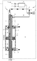
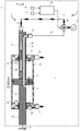
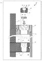
- FIG. 1 is a cross-sectional view showing a schematic configuration of a fluid injection or suction device according to a first embodiment.
- the fluid injection or suction device (hereinafter, simply referred to as “fluid device”) 1 is incorporated into the filtration device as a filter cleaning function, and is filtered by injecting the fluid into the filter or by sucking the fluid from the filter. It is used for the purpose of removing traps adhering to the filter by the filtration function of the device.
- the fluid device 1 includes a piston / cylinder mechanism 2, an external piping system 3 connected to the piston / cylinder mechanism 2, and a control system 4.
- the piston / cylinder mechanism 2 is a mechanism that injects a fluid while moving the injection position of the fluid, or sucks the fluid while moving the suction position of the fluid, and is a space that is the target of the injection or suction of the fluid (hereinafter,). , "Target space”) is placed in E.
- the piston / cylinder mechanism 2 is mainly composed of a moving cylinder 11, a piston 12, a first guide 13 and a second guide 14.
- the moving cylinder 11 is formed in a hollow tubular shape having a uniform cross section, and the piston 12 having a circumferential outer shape following the inner peripheral surface of the moving cylinder 11 is relative to the moving cylinder 11 between the openings at both ends thereof. It is inserted so that it can be moved.
- the first guide 13 and the second guide 14 are formed in the shape of a solid rod extending uniformly in cross section, and the area of their circumferential outer shape is smaller than the area of the peripheral outer shape of the piston 12, and the following states are obtained. It is connected to or integrally molded with the piston 12 as described above. That is, the first guide 13 extends outward from the portion of the inserted piston 12 facing the direction of the one end opening of the moving cylinder 11 through the one end opening.
- the second guide 14 extends outward from the portion of the inserted piston 12 facing the other end opening of the moving cylinder 11 via the other end opening. At least one of the first guide 13 and the second guide 14 (the second guide 14 in the illustrated example) is fixed to the external structure F outside the piston / cylinder mechanism 2 (may be the target space E; the same applies hereinafter). , The piston 12 is supported via at least one of the guides 13, 14. In this way, the piston / cylinder mechanism 2 is configured such that the moving cylinder 11 reciprocates while being guided by the guides 13 and 14 while being in sliding contact with the piston 12.
- the moving cylinder 11 is formed in a straight tubular shape, and the guides 13 and 14 follow the shape of the moving cylinder 11 from the piston 12 inserted in the moving cylinder 11 to the moving cylinder 11. It shall extend linearly outward through the rear part of the opening at both ends.
- the moving cylinder 11 linearly moves in the direction D1 from the piston 12 toward the first guide 13 or in the direction D2 from the piston 12 toward the second guide 14.
- various directions such as a vertical direction and a horizontal direction can be selected according to the installation posture of the piston / cylinder mechanism 2.
- the first guide 13 penetrates the first blocking member 15 so as to be relatively movable
- the second guide 14 penetrates the second blocking member 16 so as to be relatively movable.
- the guides 13 and 14 guide the movement of the moving cylinder 11 by the outer peripheral surface thereof slidingly contacting the inner peripheral surface of the through hole of the closing members 15 and 16.
- annular sealing member 17 such as an O-ring is held in a groove formed in a recessed shape over the entire circumference on the inner peripheral surface of the through hole of the first closing member 15 facing the outer peripheral surface of the first guide 13. Ru. Further, in the groove formed as a recess over the entire circumference on the inner peripheral surface of the through hole of the second closing member 16 facing the outer peripheral surface of the second guide 14, the annular seal member 18 similar to the seal member 17 is formed. Is retained.
- the sealing members 17 and 18 are configured to come into contact with the outer peripheral surfaces of the guides 13 and 14 to keep the inside and outside of the moving cylinder 11 liquidtight or airtight.
- the internal space of the moving cylinder 11 closed by the two closing members 15 and 16 is divided into two spaces of the first fluid chamber 19 and the second fluid chamber 20 by the inserted piston 12.
- the first fluid chamber 19 is defined by the piston 12, the first closing member 15, the moving cylinder 11, and the first guide 13, and the second fluid chamber 20 is the piston 12, the second closing member 16, and the moving. It is defined by the cylinder 11 and the second guide 14.
- the first fluid chamber 19 and the second fluid chamber 20 are cylindrical spaces.
- the first fluid chamber 19 and the target space E communicate with the moving body such as the moving cylinder 11 and the closing members 15 and 16 that move with respect to the relative stationary body such as the piston 12 and the guides 13 and 14.
- the first communication passage 22 is formed.
- the first communication passage 22 is bored in the first closing member 15.
- the moving body is formed with a second communication passage 23 that communicates the second fluid chamber 20 and the target space E.
- the second passage 23 is bored in the second closing member 16.
- the first connecting passage 22 is provided with a hollow tubular first nozzle 24 protruding into the target space E, and similarly, the second connecting passage 23 is provided with a hollow tubular second nozzle protruding into the target space E. 25 is provided.
- the first nozzle 24 and the second nozzle 25 transfer the fluid in the fluid chambers 19 and 20 to the target space E according to the type of the fluid pressure source (described later) of the external piping system 3 connected to the piston / cylinder mechanism 2. It is jetted or the fluid in the target space E is sucked into the fluid chambers 19 and 20.
- the first nozzle 24 is extremely smaller than the effective area (hereinafter, referred to as “first effective pressure receiving area”) in which the fluid pressure in the first fluid chamber 19 acts on the direction D1 on the inner surface of the first fluid chamber 19. It has a flow path cross-sectional area.
- the second nozzle 25 is extremely smaller than the effective area of the inner surface of the second fluid chamber 20 in which the fluid pressure in the second fluid chamber 20 acts in the direction D2 (hereinafter referred to as “second effective pressure receiving area”). It has a flow path cross-sectional area.
- the first effective pressure receiving area and the second effective pressure receiving area are common cylinder effective pressure receiving areas S, and the flow path cross-sectional area of the first nozzle 24 and the flow path of the second nozzle 25. It is assumed that the cross-sectional areas are common to each other.
- a first internal flow path 26 for communicating and connecting the first fluid chamber 19 and the external piping system 3 is formed inside the first guide 13.
- the first internal flow path 26 is formed at the extended end portion of the first guide 13 from the first inner opening 27 which faces the first fluid chamber 19 in the vicinity of the piston 12 of the first guide 13. It extends to a first outer opening 28 that faces the outside of the piston / cylinder mechanism 2.
- the first outer opening 28 is provided with a first connector 29 for communicating and connecting the first internal flow path 26 with the external piping system 3.
- a second internal flow path 30 for communicating and connecting the second fluid chamber 20 and the external piping system 3 is formed inside the first guide 13, the piston 12, and the second guide 14, a second internal flow path 30 for communicating and connecting the second fluid chamber 20 and the external piping system 3 is formed inside the first guide 13, the piston 12, and the second guide 14, a second internal flow path 30 for communicating and connecting the second fluid chamber 20 and the external piping system 3 is formed inside the first guide 13, the piston 12, and the second guide 14, a second internal flow path 30 for communicating and connecting the second fluid chamber 20 and the external piping system 3 is formed inside the first guide 13, the piston 12, and the second guide 14, a second internal flow path 30 for communicating and connecting the second fluid chamber 20 and the external piping system 3.
- the piston / cylinder mechanism 2 configured as described above has almost the same configuration as the fluid supply / suction means disclosed in Japanese Patent Application Laid-Open No. 2016-203111.
- this fluid supply / suction means is different from the piston / cylinder mechanism 2 in that it includes an orifice flow path 34 bored in the piston 12.
- the orifice flow path 34 has a short-circuited flow path that connects (short-circuits) the first fluid chamber 19 and the second fluid chamber 20 in communication, and an orifice (throttle) as a narrowing means for narrowing the short-circuited flow path.
- the flow path cross-sectional area of the orifice flow path 34 is set to an extremely small value as compared with the cylinder effective pressure receiving area S described above.
- the piston 12 comes into contact with the second closing member 16 when the moving cylinder 11 moves in the direction D1, or by contacting the first closing member 15 when the moving cylinder 11 moves in the direction D2. It also functions as a stopper that regulates the movement of the eleven.
- the position of the first closing member 15 when the movement of the moving cylinder 11 in the direction D1 is restricted is called the D1 restricted position, and the fluid when the movement of the moving cylinder 11 is restricted at such a position.
- the state of the device 1 is referred to as a D1 regulated state.
- the position of the second closing member 16 when the movement of the moving cylinder 11 in the direction D2 is restricted is called a D2 restricted position, and the fluid device when the movement of the moving cylinder 11 is restricted at such a position.
- the state of 1 is referred to as the D2 regulated state.
- the first closing member 15 closes the first inner opening 27, making fluid flow difficult between the target space E and the first internal flow path 26. Therefore, the first closing member 15 has a first protruding portion 35, a part of which protrudes toward the first fluid chamber 19. The amount of protrusion of the first protrusion 35 is such that when the first protrusion 35 comes into contact with the piston 12 in the D2 regulated state, the first closing member 15 does not completely close the first inner opening 27 of the piston 12. Is set to be separated from.
- the second closing member 16 closes the second inner opening 31 and fluid flow becomes difficult between the target space E and the second internal flow path 30. Therefore, the second closing member 16 has a second protruding portion 36 in which a part thereof protrudes toward the second fluid chamber 20. The amount of protrusion of the second protruding portion 36 is such that when the second protruding portion 36 comes into contact with the piston 12 in the D1 regulated state, the second closing member 16 does not completely close the second inner opening 31 of the piston 12. Is set to be separated from.
- the external piping system 3 includes a first external piping 37, a second external piping 38, a pressure connecting pipe 39, a flow path switching valve 40, and a fluid pressure source 41.
- One end of the first external pipe 37 is connected to the first connector 29, and the other end is connected to the flow path switching valve 40.
- One end of the second external pipe 38 is connected to the above-mentioned second connector 33, and the other end is connected to the flow path switching valve 40.
- One end of the pressure connection pipe 39 is connected to the flow path switching valve 40, and the other end is connected to the fluid pressure source 41.
- the flow path switching valve 40 includes a first port to which the first external pipe 37 is connected, a second port to which the second external pipe 38 is connected, and a pressure source port to which the pressure connection pipe 39 is connected.
- a three-way solenoid valve with is used.
- the three-way solenoid valve is configured to be able to block at least one of the first port and the second port by external control. By switching the port of the three-way solenoid valve, the fluid can flow through the piston / cylinder mechanism 2 between the fluid pressure source 41 and the target space E in either the first flow path system or the second flow path system. It will be possible.
- the first flow path system is composed of a first external pipe 37, a first internal flow path 26, a first fluid chamber 19, a first continuous passage 22, and a first nozzle 24.
- the second flow path system is composed of a second external pipe 38, a second internal flow path 30, a second fluid chamber 20, a second communication passage 23, and a second nozzle 25.
- two two-way solenoid valves may be used instead of the three-way solenoid valve.
- the pressure connection pipe 39 connected to the fluid pressure source 41 is used as a bifurcated pipe
- the first external pipe 37 is connected to one of the bifurcated pipes via a two-way solenoid valve to form a bifurcated pipe.
- a second external pipe 38 may be connected to the other branch port of the pipe via a two-way solenoid valve.
- the first flow path system enables the flow of fluid through the piston / cylinder mechanism 2 between them.
- the fluid pressure source 41 and the target space E are opened.
- the second flow path system enables the flow of fluid between the two and the piston / cylinder mechanism 2.
- the flow path switching valve 40 allows the flow of fluid through the piston / cylinder mechanism 2 between the fluid pressure source 41 and the target space E on either the first flow path system or the second flow path system. Any type of solenoid valve that can be externally controlled can be used.
- a high pressure source is used when injecting a fluid from the fluid chambers 19 and 20 to the target space E via the nozzles 24 and 25, while the fluid from the target space E via the nozzles 24 and 25.
- a low pressure source is used to aspirate the fluid into the chambers 19 and 20.
- the high pressure source generates a fluid having a pressure higher than the pressure of the target space E (hereinafter referred to as “target space pressure”) Ptgt .
- the generated pressure of the high-pressure source is ⁇ p such as the flow path loss from the high-pressure source to the nozzles 24 and 25 (first flow path system, second flow path system, etc.) with respect to the target space pressure Ptgt . It is set to a higher pressure than the considered pressure ( Ptgt + ⁇ p).
- the high-pressure source includes, for example, a fluid storage tank for storing the fluid, a pump for constantly pressurizing the fluid in the fluid storage tank, and may further include a regulator, a buffer tank, or the like to keep the pressure constant. ..
- the high pressure source is omitted and the pressure source is omitted.
- the port may be open to the atmosphere.
- the low pressure source produces a fluid lower than the target space pressure P tgt .
- the generated pressure of the low-voltage source is ⁇ p such as the flow path loss from the nozzles 24 and 25 to the low-pressure source (first flow path system, second flow path system, etc.) with respect to the target space pressure Ptgt . It is set to a lower pressure than the considered pressure ( Ptgt - ⁇ p).
- the low pressure source may include, for example, a vacuum pump, and may further include a regulator, a buffer tank, or the like in order to keep the pressure constant.
- the target space pressure P tgt is higher than the pressure obtained by adding ⁇ p such as the flow path loss from the nozzles 24 and 25 to the atmospheric pressure, the low pressure source is omitted and the pressure source port is opened to the atmosphere. You may do it.
- the control system 4 includes a first proximity detector 42, a second proximity detector 43, and a controller 44.
- the first proximity detector 42 is configured to output a detection signal when it detects that the moving cylinder 11 has moved to the D1 restricted position.
- the second proximity detector 43 is arranged and configured to output a detection signal when it detects that the moving cylinder 11 has moved to the D2 restricted position.
- various detection methods such as a contact type using a limit switch or the like and a non-contact type using a proximity sensor using light, magnetism, or electrostatic induction can be adopted.
- the controller 44 switches the port of the flow path switching valve 40 by outputting a control signal based on the two output signals of the first proximity detector 42 and the second proximity detector 43.
- the controller 44 includes a microcomputer having a processor such as a CPU (Central Processing Unit).
- This microcomputer has a ROM (ReadOnlyMemory), a RAM (RandomAccessMemory), an input / output interface, etc., which are communicably connected to the processor by an internal bus.
- the controller 44 controls the operation of the fluid device 1 by software processing in which the processor of the microcomputer reads the operation control program of the fluid device 1 from the ROM into the RAM and executes it.
- the operation control of the fluid device 1 in the controller 44 does not exclude that a part or the whole thereof is executed by the hardware configuration.
- various fluids may be used according to the application of the fluid device 1.
- various fluids may be used according to the application of the fluid device 1.
- can for example, in the case of cleaning use, in addition to water, an aqueous solution of detergent, an organic solvent, oil, etc., and as a gas, air or various gases can be used, and in the case of painting use, various paints are used.
- various spraying liquids can be used.
- the viscosity is preferably 0.2 cP to 1000 cP.
- an injection mode which is an operation method of the fluid device 1 when injecting fluid from the fluid chambers 19 and 20 to the target space E via the nozzles 24 and 25, will be described.
- the fluid pressure source 41 a high pressure source having a generated pressure PH higher than the target space pressure P tgt and a sending flow rate Q H is used.
- the first flow path system and the second flow path system are filled with the fluid. Unless otherwise specified, the potential energy and pressure loss of the fluid shall not be considered.
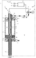
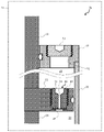
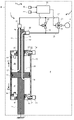
- FIG. 2 shows a state in which the moving cylinder 11 is moving in the direction D1 in the injection mode.
- the controller 44 outputs a control signal for closing the second port to the three-way solenoid valve in order to move the moving cylinder 11 in the direction D1.
- the controller 44 outputs a control signal for closing the second port to the three-way solenoid valve in order to move the moving cylinder 11 in the direction D1.
- the high-pressure source and the first external pipe 37 are communicated with each other via the first port of the three-way solenoid valve, whereby the fluid from the high-pressure source to the first fluid chamber 19 is connected. Is sent out.
- the fluid in the first fluid chamber 19 When the fluid is sent from the high pressure source to the first fluid chamber 19, the fluid in the first fluid chamber 19 is ejected to the target space E through the first nozzle 24 due to the increase in the internal pressure of the first fluid chamber 19, and the first fluid chamber 19 is used. 1
- the volume of the fluid chamber 19 is increased to move the moving cylinder 11 in the direction D1. Then, since the volume of the second fluid chamber 20 is reduced, the fluid in the second fluid chamber 20 is injected into the target space E through the second nozzle 25.
- the balance of the forces acting on the moving cylinder 11 moving in the direction D1 at a constant speed V1 in the injection mode is the generated pressure PH of the high pressure source, the internal pressure P B1 of the second fluid chamber 20, and the frictional force R (>. It is represented by the following equation (1) using 0) and the cylinder effective pressure receiving area S.
- the left side is the force acting on the direction D1 of the moving cylinder 11
- the right side is the force acting on the direction D2 of the moving cylinder 11.
- the generated pressure PH of the high voltage source is used as the internal pressure PA1 of the first fluid chamber 19 without considering the pressure loss as described above.
- the frictional force R1 is a frictional force generated between the moving cylinder 11 and the piston 12 (or the sealing member 21) or between the closing members 15, 16 (or the sealing members 17, 18) and the guides 13, 14. be.
- PH x S P B1 x S + R 1 ... (1)
- the above equation (1) is modified and expressed by the following equation (2). From this, it can be seen that the internal pressure PA1 of the first fluid chamber 19 has a higher pressure than the internal pressure PB1 of the second fluid chamber 20 ( PA1 > PB1 ).
- the balance between the inflow rate and the outflow rate in the moving cylinder 11 is calculated by the following equation (3) using the transmission flow rate QH of the high pressure source, the injection flow rate QA1 of the first nozzle 24, and the injection flow rate QB1 of the second nozzle 25. ).
- the left side is the inflow rate to the moving cylinder 11
- the right side is the outflow rate from the moving cylinder 11.
- Q H Q A1 + Q B1 ...
- the volume of the second fluid chamber 20 decreases at the volume reduction rate [m 3 / s] indicated by the product of the speed V 1 of the moving cylinder 11 and the cylinder effective pressure receiving area S.
- the second fluid chamber 20 since the internal pressure PA1 of the first fluid chamber 19 is higher than the internal pressure PB1 of the second fluid chamber 20, the second fluid chamber 20 has a minute flow rate q 1 via the orifice flow path 34.
- the fluid (> 0) flows in from the first fluid chamber 19.
- the speed V1 of the moving cylinder 11 can be obtained by the following equation ( 5 ).
- V 1 (Q B1 -q 1 ) / S ... (5)
- the balance between the inflow flow rate and the outflow flow rate in the moving cylinder 11 is the same as in the above equation (3), that is, the transmission flow rate QH of the high pressure source, the injection flow rate QA1'of the first nozzle 24, and the injection of the second nozzle 25. It is expressed by the following equation (7) using the flow rate Q B1 '.
- the left side is the inflow rate to the moving cylinder 11, and the right side is the outflow rate from the moving cylinder 11.
- Q H Q A1 '+ Q B1 '... (7)
- the volume of the second fluid chamber 20 decreases at the volume decrease rate [m 3 / s] indicated by the product of the speed V 1'of the moving cylinder 11 and the cylinder effective pressure receiving area S, similarly to the above.
- the piston / cylinder mechanism 2 does not include the orifice flow path 34, no fluid flow occurs between the first fluid chamber 19 and the second fluid chamber 20. Therefore, since the second nozzle 25 injects the fluid at a flow rate equal to the volume reduction rate of the second fluid chamber 20, the following equation (8) is established for the injection flow rate Q B1 '.
- Q B1 ' S ⁇ V 1 '... (8)
- the injection flow rate of the first nozzle 24 and the injection flow rate of the second nozzle 25 are reduced. It is possible to reduce the speed of the moving cylinder 11 while suppressing the pressure.
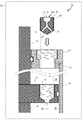
- FIG. 3 shows the D1 regulation state of the moving cylinder 11 in the injection mode.
- the volume of the first fluid chamber 19 becomes the maximum and the volume of the second fluid chamber 20 becomes the minimum, and the volume change stops.
- the moving cylinder 11 is stopped at the D1 regulated position, the fluid is still sent from the high pressure source to the first fluid chamber 19, so that the fluid injection from the first nozzle 24 continues.
- the volume change of the second fluid chamber 20 is stopped, a small flow rate of fluid flowing from the first fluid chamber 19 to the second fluid chamber 20 through the orifice flow path 34 flows from the second nozzle 25 to the target space E. It just leaks to.
- the controller 44 When the controller 44 detects that the moving cylinder 11 has stopped at the D1 restricted position based on the output signal of the first proximity detector 42, the controller 44 is a three-way solenoid valve in order to switch the moving direction of the moving cylinder 11 to the direction D2. On the other hand, a control signal for closing the first port is output.
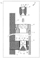
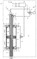
- FIG. 4 shows a state in which the moving cylinder 11 is moving in the direction D2 in the injection mode.
- the controller 44 controls the closing of the first port of the three-way solenoid valve, so that the high-voltage source and the second external pipe 38 are communicated with each other via the second port of the three-way solenoid valve, whereby the high-voltage source is connected.
- the fluid is sent out from the second fluid chamber 20 to the second fluid chamber 20.
- the fluid in the second fluid chamber 20 is injected into the target space E through the second nozzle 25 due to the increase in the internal pressure P B1 of the second fluid chamber 20.
- the volume of the second fluid chamber 20 is increased to move the moving cylinder 11 in the direction D2. Then, the volume of the first fluid chamber 19 decreases, the internal pressure PA1 rises, and the fluid in the first fluid chamber 19 is injected into the target space E through the first nozzle 24.
- the above equations (1) to (13) are established by the following. That is, in the above equations (1) to (13), the internal pressures PA1 and PA1'of the first fluid chamber 19 and the internal pressures PB1 and PB1'of the second fluid chamber 20 are interchanged with each other, and the first nozzle 24 It is established by exchanging the injection flow rates Q A1 and Q A1'of the second nozzle 25 and the injection flow rates Q B1 and Q B1'of the second nozzle 25, respectively.
- the speed of the moving cylinder 11 in the direction D2 is reduced while suppressing the decrease in the injection flow rate of the first nozzle 24 and the injection flow rate of the second nozzle 25. Can be done.
- FIG. 5 shows the D2 regulation state of the moving cylinder 11 in the injection mode.
- the volume of the first fluid chamber 19 becomes the minimum and the volume of the second fluid chamber 20 becomes the maximum, and the volume change stops.
- the moving cylinder 11 is stopped at the D2 regulated position, the fluid is still sent from the high pressure source to the second fluid chamber 20, so that the fluid injection from the second nozzle 25 continues.
- the volume change of the first fluid chamber 19 is stopped, a small flow rate of fluid flowing from the second fluid chamber 20 to the first fluid chamber 19 through the orifice flow path 34 flows from the first nozzle 24 to the target space E. It just leaks to.
- the controller 44 When the controller 44 detects that the moving cylinder 11 has stopped at the D2 restricted position based on the output signal of the second proximity detector 43, the controller 44 is a three-way solenoid valve in order to switch the moving direction of the moving cylinder 11 to the direction D1. On the other hand, a control signal for closing the second port is output. As a result, as shown in FIG. 2, the moving cylinder 11 moves in the direction D1 again.
- a suction mode which is an operation method of the fluid device 1 when the fluid is sucked from the target space E to the fluid chambers 19 and 20 via the nozzles 24 and 25, will be described.
- the fluid pressure source 41 a low pressure source having a generated pressure PL lower than the target space pressure P tgt and a suction flow rate QL is used.
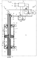
- FIG. 6 shows a state in which the moving cylinder 11 is moving in the direction D1 in the suction mode.
- the controller 44 outputs a control signal for closing the first port of the three-way solenoid valve.
- the low pressure source and the second external pipe 38 are communicated with each other via the second port of the three-way solenoid valve, whereby the fluid from the second fluid chamber 20 to the low pressure source is connected. Is sucked in.
- the fluid in the target space E is sucked into the second fluid chamber 20 through the second nozzle 25 due to the decrease in the internal pressure of the second fluid chamber 20, and the second fluid chamber 20 is sucked into the second fluid chamber 20.
- the volume of the fluid chamber 20 is reduced to move the moving cylinder 11 in the direction D1.
- the volume of the first fluid chamber 19 increases, and the fluid in the target space E is sucked into the first fluid chamber 19 through the first nozzle 24.
- the balance of the forces acting on the moving cylinder 11 moving in the direction D1 at a constant speed V2 in the suction mode is the generated pressure PL of the low pressure source, the internal pressure PA2 of the first fluid chamber 19, and the frictional force R2 ( > 0) and the cylinder effective pressure receiving area S are represented by the following equation (14).
- the left side is the force acting on the direction D1 of the moving cylinder 11
- the right side is the force acting on the direction D2 of the moving cylinder 11.
- the generated pressure PL of the low pressure source is used as the internal pressure P B2 of the second fluid chamber 20 without considering the pressure loss as described above.
- PA2 x S PL x S + R 2 ... (14)
- the above equation (14) is modified and shown by the following equation (15). From this, it can be seen that the internal pressure PA2 of the first fluid chamber 19 has a higher pressure than the internal pressure PB2 of the second fluid chamber 20 ( PA2 > PB2 ).
- the balance between the inflow rate and the outflow rate in the moving cylinder 11 is calculated by the following equation (16) using the suction flow rate QL of the low pressure source, the suction flow rate QA2 of the first nozzle 24, and the suction flow rate QB2 of the second nozzle 25. ).
- the left side is the outflow flow rate from the moving cylinder 11
- the right side is the inflow flow rate to the moving cylinder 11.
- Q L Q A2 + Q B2 ...
- the volume of the first fluid chamber 19 increases at the volume increase rate [m 3 / s] indicated by the product of the speed V 2 of the moving cylinder 11 and the cylinder effective pressure receiving area S.
- the minute flow rate q 2 from the first fluid chamber 19 is passed through the orifice flow path 34.
- the fluid (> 0) flows out to the second fluid chamber 20.
- the balance between the inflow flow rate and the outflow flow rate in the moving cylinder 11 is the suction flow rate QL of the low pressure source, the suction flow rate QA2'of the first nozzle 24, and the suction of the second nozzle 25, as in the above equation (16). It is expressed by the following equation (20) using the flow rate Q B2 '.
- Q L Q A2 '+ Q B2 '... (20)
- the volume of the first fluid chamber 19 increases at the volume increasing speed [m 3 / s] indicated by the product of the speed V 2'of the moving cylinder 11 and the cylinder effective pressure receiving area S, similarly to the above.
- the piston / cylinder mechanism 2 does not include the orifice flow path 34, no fluid flow occurs between the first fluid chamber 19 and the second fluid chamber 20. Therefore, since the first nozzle 24 sucks the fluid at a flow rate equal to the volume increase rate of the first fluid chamber 19, the following equation (21) is established for the suction flow rate QA2 '.
- Q A2 ' S ⁇ V 2 '... (21)
- the suction flow rate of the first nozzle 24 and the suction flow rate of the second nozzle 25 are reduced. It is possible to reduce the speed of the moving cylinder 11 while suppressing the pressure.
- FIG. 7 shows the D1 regulation state of the moving cylinder 11 in the suction mode.
- the volume of the first fluid chamber 19 becomes the maximum and the volume of the second fluid chamber 20 becomes the minimum, and the volume change stops.
- the moving cylinder 11 is stopped at the D1 regulated position, the fluid is still sucked from the second fluid chamber 20 to the low pressure source, so that the fluid suction through the second nozzle 25 continues.
- the volume change of the first fluid chamber 19 is stopped, a small flow rate of fluid flowing out from the first fluid chamber 19 to the second fluid chamber 20 through the orifice flow path 34 flows from the target space E to the first fluid. It only flows into the chamber 19 through the first nozzle 24.
- the controller 44 When the controller 44 detects that the moving cylinder 11 has stopped at the D1 restricted position based on the output signal of the first proximity detector 42, the controller 44 is a three-way solenoid valve in order to switch the moving direction of the moving cylinder 11 to the direction D2. On the other hand, a control signal for closing the second port is output.
- FIG. 8 shows a state in which the moving cylinder 11 is moving in the direction D2 in the suction mode.
- the low voltage source and the first external pipe 37 are communicated and connected to each other via the first port of the three-way solenoid valve by the closing control of the second port of the three-way solenoid valve by the controller 44, whereby the first one.
- the fluid is sucked from the fluid chamber 19 into the low pressure source.
- the fluid in the target space E is sucked into the first fluid chamber 19 through the first nozzle 24 due to the decrease in the internal pressure PA2 of the first fluid chamber 19.
- the volume of the first fluid chamber 19 is reduced to move the moving cylinder 11 in the direction D2.
- the volume of the second fluid chamber 20 increases, the internal pressure P B2 decreases, and the fluid in the target space E is sucked into the second fluid chamber 20 through the second nozzle 25.
- the above equations (14) to (26) are established by the following. That is, in the above equations (14) to (26), the internal pressures PA2 and PA2'of the first fluid chamber 19 and the internal pressures PB2 and PB2'of the second fluid chamber 20 are interchanged with each other, and the internal pressures P B2 and P B2'of the second fluid chamber 20 are exchanged with each other. It is established by exchanging the suction flow rates Q A2 and Q A2'and the suction flow rates Q B2 and Q B2'of the second nozzle 25.
- the speed of the moving cylinder 11 in the direction D2 is reduced while suppressing a decrease in the suction flow rate of the first nozzle 24 and the suction flow rate of the second nozzle 25. Can be done.
- FIG. 9 shows the D2 regulation state of the moving cylinder 11 in the suction mode.
- the volume of the first fluid chamber 19 becomes the minimum and the volume of the second fluid chamber 20 becomes the maximum, and the volume change stops.
- the moving cylinder 11 is stopped at the D2 restricted position, the fluid is still sucked from the first fluid chamber 19 to the low pressure source, so that the fluid suction through the first nozzle 24 continues.
- the volume change of the second fluid chamber 20 is stopped, a small flow rate of fluid flowing out from the second fluid chamber 20 to the first fluid chamber 19 through the orifice flow path 34 flows from the target space E to the second fluid. It only flows into the chamber 20 through the second nozzle 25.
- the controller 44 When the controller 44 detects that the moving cylinder 11 has stopped at the D2 restricted position based on the output signal of the second proximity detector 43, the controller 44 is a three-way solenoid valve in order to switch the moving direction of the moving cylinder 11 to the direction D1. On the other hand, a control signal for closing the first port is output. As a result, as shown in FIG. 6, the moving cylinder 11 moves in the direction D1 again.
- the piston / cylinder mechanism 2a of the fluid device 1a has a through hole 45 penetrating from the portion of the piston 12 facing the first fluid chamber 19 to the portion facing the second fluid chamber 20. It differs from the piston / cylinder mechanism 2 in that a separate plug 46 having an orifice flow path 34 formed therein is detachably attached to the through hole 45. Note that FIG. 10 shows the main part of the piston / cylinder mechanism 2a before the plug is mounted, and FIG. 11 shows the main part of the piston / cylinder mechanism 2a in the plug mounting completed state.
- a substantially columnar plug 46 is screwed into a through hole 45 having a circular cross section and mounted.
- a male screw 47 spirally formed on the outer peripheral surface of the plug 46 about the axis of screw rotation of the plug 46 is screwed or screwed into a female screw 48 formed on the inner peripheral surface of a through hole 45 having a substantially circular cross section.
- An orifice flow path 34 is formed between both end faces 49 and 50 in the axial direction of the plug 46, and the first fluid chamber 19 and the second fluid chamber 20 are connected to the orifice flow path with the plug 46 screwed into the through hole 45. Communicate via 34.
- a fitting groove 51 is formed in a recess on the end face (hereinafter referred to as "first end face") 49 facing the first fluid chamber 19 among the end faces 49 and 50 of the plug 46 in the axial direction.
- the fitting groove 51 is an engaging portion that transmits the axial rotational force by fitting the tip portion of the shaft-shaped tool in order to rotate the plug 46 and screw it into the through hole 45 or screw it out from the through hole 45.
- the fitting groove 51 is a shaft-shaped tool to be used, for example, a hexagonal hole to which the tip of a hexagonal bar spanner, which is a shaft-shaped tool, is fitted, or a concave groove to which the tip of a flat-blade screwdriver, which is a shaft-shaped tool, is fitted.
- the orifice flow path 34 can be provided without interfering with the fitting groove 51, but if the first end surface 49 does not have an area margin, the following may be used. That is, as shown in FIGS. 10 and 11, the orifice flow path 34 faces the second fluid chamber 20 from the bottom of the fitting groove 51, for example, the bottom of the hexagonal hole into which the tip of the hexagon wrench is fitted. It may extend to the end face (hereinafter referred to as "second end face") 50.
- a working through hole 52 is formed in the first closing member 15 facing the first end surface 49 of the plug 46 screwed into the through hole 45 with the first fluid chamber 19 interposed therebetween.
- This work through hole 52 is used when the plug 46 is replaced, and the plug 46 is inserted into the work through hole 52 with the tip of the shaft-shaped tool fitted in the fitting groove 51 of the plug 46. , The plug 46 can be screwed into the through hole 45.
- the work through hole 52 is closed by screwing or the like of the normally closed lid 53 except when the plug 46 is replaced.
- the speed reduction amount of the moving cylinder 11 is set according to the values of the minute flow rates q 1 and q 2 of the orifice flow path 34, and the values of the minute flow rates q 1 and q 2 . Varies according to the flow path cross-sectional area of the orifice flow path 34. Therefore, if a plurality of plugs 46 are prepared in advance and the orifice flow paths 34 of these plugs 46 are formed with various flow path cross-sectional areas, a plug 46 having an appropriate flow path cross-sectional area is selected and attached to the through hole 45. By doing so, the speed of the moving cylinder 11 can be reduced by a desired amount of reduction.
- FIG. 12 shows the main part of the piston / cylinder mechanism 2a before the plug is mounted
- FIG. 13 shows the main part of the piston / cylinder mechanism 2a in the plug mounting completed state.
- the plug 46a of the present modification is different from the plug 46 in that the second end surface 50 of the plug 46 has a conical surface 54 formed by bulging in a conical shape or a conical shape coaxial with the axis.
- the through hole 45a of the present modification faces the conical surface 54 of the plug 46a when the plug 46a is screwed, and has an inner facing conical surface 55 having a shape following the conical surface 54 of the plug 46a. It differs from the through hole 45 in that it has a part of the peripheral surface.
- the opening 56 on the second fluid chamber 20 side of the orifice flow path 34 of the plug 46a is a gap 57 formed between the conical surface 54 and the facing conical surface 55 when the plug 46a is screwed into the through hole 45a. It is formed to face. As a result, the gap 57 formed between the conical surface 54 and the facing conical surface 55 forms a part of the orifice flow path 34.
- a plurality of openings 56 on the second fluid chamber 20 side may be formed, and in this case, the orifice flow path 34 may be branched into a plurality of openings inside the plug 46a as shown in the figure and may be connected to each opening 56.
- the openings 56 may individually have an orifice flow path 34.
- the orifice flow path 34 of the plug 46a includes the gap 57.
- the gap 57 varies depending on the amount of screwing of the male screw 47 of the plug 46a with respect to the female screw 48 of the through hole 45a. Therefore, the orifice flow path 34 has, as a throttle means, a variable throttle valve in which the interval between the gaps 57 is the throttle opening of the flow path. Therefore, according to the plug 46a, the speed of the moving cylinder 11 can be reduced by a desired reduction amount by adjusting the screwing amount, and the need for plug replacement can be eliminated.
- the orifice flow path 34 is provided with a variable throttle valve realized by the gap 57, the orifice is omitted from the orifice flow path 34, and the first fluid chamber 19 and the second fluid chamber 20 are simply separated. It may be a short-circuit flow path for communication connection (short circuit).
- FIG. 14 basically shows the main part of the piston / cylinder mechanism 2a before the plug is mounted, but the plug is shown by a broken line when the plug is fully mounted.
- the plug 46b of this modification is different from the plug 46 in that the second end surface 50 of the plug 46 has a conical surface 54a formed by retreating in a conical shape or a conical shape coaxial with the axis. ..
- the conical structure 58 forming the facing conical surface 55a facing the conical surface 54a when the plug 46b is screwed into the through hole 45 does not block the through hole 45 on the second fluid chamber 20 side of the plug 46b.
- the orifice flow path 34 is formed on the axis of the plug 46b and connected to the orifice flow path 34 in order to uniformly supply the fluid to the gap 57a formed between the conical surface 54a and the facing conical surface 55a.
- the gap 57a forms a part of the orifice flow path 34.
- the orifice flow path 34 of the plug 46b includes the gap 57a.
- the gap 57a changes according to the amount of screwing of the male screw 47 of the plug 46a with respect to the female screw 48 of the through hole 45. Therefore, the orifice flow path 34 has a variable throttle valve as a throttle means, in which the interval between the gaps 57a is set as the throttle opening of the flow path. Therefore, according to the plug 46b, the speed of the moving cylinder 11 can be reduced by a desired reduction amount by adjusting the screwing amount, and the need for plug replacement can be eliminated.
- the orifice flow path 34 is provided with a variable throttle valve realized by the gap 57a, the orifice is omitted from the orifice flow path 34, and the first fluid chamber 19 and the second fluid chamber 20 are simply separated. It may be a short-circuit flow path for communication connection (short circuit).
- FIG. 15 shows the main part of the piston / cylinder mechanism 2a before the plug is mounted
- FIG. 16 shows the main part of the piston / cylinder mechanism 2a in the plug mounting completed state.
- the valve body 59 is provided on the second fluid chamber 20 side of the plug 46 mounted in the through hole 45b.
- the valve body 59 allows fluid inflow from the first fluid chamber 19 to the second fluid chamber 20 through the orifice flow path 34, and also allows the orifice flow path 34 from the second fluid chamber 20 to the first fluid chamber 19. It has a function of inhibiting the inflow of fluid through the
- the through hole 45b is different from the through hole 45 in that the plug 46 is configured so that the plug 46 can be screwed only halfway from the first fluid chamber 19 side to the second fluid chamber 20 side.
- the valve body 59 is held on the second fluid chamber 20 side of the through hole 45b with respect to the second end surface 50 of the plug 46 screwed into the through hole 45b so as to be translateable in the through hole 45b.
- the valve body 59 has one or more fluid flow holes 60 for passing the fluid flowing out of the orifice flow path 34 of the plug 46 screwed into the through hole 45b to the second fluid chamber 20.
- valve body 59 When the valve body 59 moves toward the screwed plug 46 in the through hole 45b, the valve body 59 opens an opening on the second end surface 50 side of the orifice flow path 34 or an intermediate flow path (not shown) connected to the opening. It is formed to occlude (see valve body 59 shown by a broken line in FIG. 16). That is, the fluid flow hole 60 is formed so as not to overlap with the opening on the second end surface 50 side of the orifice flow path 34 or the intermediate flow path (not shown above) in the penetration direction of the through hole 45b.
- valve body 59 closes the opening on the second end surface 50 side of the orifice flow path 34 or the intermediate flow path (not shown above), the fluid outflow from the second fluid chamber 20 to the first fluid chamber 19 does not occur. Be hindered. As described above, according to the valve body 59, it is possible to selectively reduce only the moving speed of the moving cylinder 11 in the direction D1 in both the injection mode and the suction mode.
- the amount of decrease in the moving speed of the moving cylinder 11 when the amount of decrease in the moving speed of the moving cylinder 11 is set individually for the direction D1 and the direction D2 in both the injection mode and the suction mode, it may be as shown in FIG. That is, a penetration configured in the piston 12 so that a plug 46'similar to the plug 46 can be screwed only halfway from the second fluid chamber 20 side to the first fluid chamber 19 side at a position different from the through hole 45b. A hole 45b'is drilled. Then, the valve body 59 ′ may be provided on the first fluid chamber 19 side of the plug 46 ′ mounted in the through hole 45b ′ as well as the valve body 59.
- the fluid in the second fluid chamber 20 passes through the orifice flow path 34'and the fluid flow hole 60' and flows to the first fluid chamber 19. Therefore, if the flow path cross-sectional areas of the two orifices of the orifice flow path 34 and the orifice flow path 34'are different, the amount of decrease in the movement speed of the moving cylinder 11 can be set individually in the direction D1 and the direction D2.
- valve bodies 59 and 59'of this modification can also be applied to the first modification in which the plug 46a is attached to the through hole 45a and the second modification in which the plug 46b is attached to the through hole 45. That is, the inner peripheral surface of the through hole 45b may be deformed to provide an intermediate flow path communicating with the gaps 57 and 57a, and the valve bodies 59 and 59'may be arranged so that the intermediate flow path can be closed.
- valve bodies 59 and 59' are not limited to the configurations shown in FIGS. 15 to 17, and are flexible so as to close the openings on the second end faces 50 and 50'sides of the orifice flow paths 34 and 34'. It may be formed of a material.
- the valve body 59 is elastically deformed when the internal pressures PA1 and PA2 of the first fluid chamber 19 become higher than the internal pressures PB1 and PB2 of the second fluid chamber 20, and the second fluid chamber 34 is the second.
- the opening on the end face 50 side is opened, and the fluid in the first fluid chamber 19 flows to the first fluid chamber 19 through the orifice flow path 34.
- the short-circuited flow path that short-circuits the first flow path system and the second flow path system passes through the short-circuit pipe 61 that appears outside the moving cylinder 11 instead of the orifice flow path 34.
- the short-circuit pipe 61 is provided with the flow rate adjusting valve 62.
- the flow rate adjusting valve 62 is a throttle valve that can steplessly adjust the passing flow rate by changing the throttle opening degree, and is an electric valve whose throttle opening degree can be controlled by the controller 44.
- the protrusions 35 and 36 are not shown.
- the short-circuit pipe 61 communicates and connects the first external pipe 37 and the second external pipe 38, and the flow rate adjusting valve 62 is arranged in the short-circuit pipe 61.
- the short-circuit pipe 61 has a connector 64 that communicates with the first fluid chamber 19 via a communication passage 63 and a connector 66 that communicates with the second fluid chamber 20 via a communication passage 65.
- a flow control valve 62 is arranged in the short-circuit pipe 61.
- the short-circuit pipe 61 communicates and connects the configurations of moving bodies such as the moving cylinder 11 to short-circuit the first flow path system and the second flow path system, or with respect to the moving body. Either the first flow path system and the second flow path system may be short-circuited by communicating the configurations of the stationary bodies that are relatively stationary with each other.
- the speed reduction amount of the moving cylinder 11 is set according to the values of the minute flow rates q 1 and q 2 of the orifice flow path 34, and the minute flow rates q 1 and q 2 are set.
- the value of varies depending on the flow path cross-sectional area of the orifice flow path 34. Therefore, the speed of the moving cylinder 11 can be reduced by a desired amount by appropriately adjusting the throttle opening degree of the flow rate adjusting valve 62.
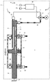
- a fluid device according to a fourth embodiment will be described with reference to FIGS. 20 and 21.
- the fluid device 1c according to the present embodiment differs from the first embodiment in the following points. That is, a short-circuit flow path that short-circuits the first flow path system and the second flow path system is formed via two short-circuit pipes 61a and 61b that appear outside the moving cylinder 11 instead of the orifice flow path 34. It differs from the first embodiment in that the first flow rate adjusting valve 62a is arranged in the first short-circuit pipe 61a and the second flow rate adjusting valve 62b is arranged in the second short-circuit pipe 61b.
- the flow rate adjusting valves 62a and 62b are electric valves similar to the flow rate adjusting valve 62.
- a first flow rate adjusting valve 62a is arranged in a first short-circuit pipe 61a that connects the pressure connection pipe 39 and the first external pipe 37 in communication, and the pressure connection pipe 39 and the second external pipe are connected.
- a second flow rate adjusting valve 62b is arranged in a second short-circuit pipe 61b that communicates with 38.
- the bifurcated pipe which is the pressure connecting pipe 39 and the first external pipe are used.
- a first flow control valve 62a is arranged in a first short-circuit pipe 61a that communicates with the 37 by bypassing the two-way solenoid valve 40a.
- the second flow rate adjusting valve 62b is arranged in the second short-circuit pipe 61b that communicates and connects the two-branch pipe, which is the pressure connection pipe 39, and the second external pipe 38, bypassing the two-way solenoid valve 40b.
- the second flow rate adjusting valve 62b opens at a predetermined throttle opening, so that the orifice flow path 34 Similarly, the fluids having the above-mentioned minute flow rates q 1 and q 2 flow between the first flow path system and the second flow path system.
- the first flow rate adjusting valve 62a opens at a predetermined throttle opening, so that the orifice flow occurs. Similar to the road 34, the fluids with the above-mentioned minute flow rates q 1 and q 2 flow between the first flow path system and the second flow path system.
- the speed of the moving cylinder 11 can be reduced while suppressing a decrease in the injection flow rate of the first nozzle 24 and the injection flow rate of the second nozzle 25.
- the speed of the moving cylinder 11 can be reduced while suppressing a decrease in the suction flow rate of the first nozzle 24 and the suction flow rate of the second nozzle 25.
- the speed reduction amount of the moving cylinder 11 is set according to the values of the minute flow rates q 1 and q 2 of the orifice flow path 34, and the minute flow rates q 1 and q 2 are set.
- the value of varies depending on the flow path cross-sectional area of the orifice flow path 34. Therefore, if the throttle opening of the first flow rate adjusting valve 62a is appropriately adjusted, the amount of decrease in speed can be reduced for the movement of the moving cylinder 11 in the direction D2 in the injection mode and for the movement of the moving cylinder 11 in the direction D1 in the suction mode. It can be set to a desired value.
- the amount of decrease in speed can be reduced for the movement of the moving cylinder 11 in the direction D1 in the injection mode and for the movement of the moving cylinder 11 in the direction D2 in the suction mode. It can be set to a desired value.
- the speed reduction amount of the moving cylinder 11 is set to a different value between when the moving cylinder 11 moves in the direction D1 and when the moving cylinder 11 moves in the direction D2. can do.
- the moving cylinder 11 instead of forming the moving cylinder 11 in a straight tubular shape and forming the guides 13 and 14 in a straight line, they may be formed as follows. That is, the moving cylinder 11 is formed in a circular shape, and the guides 13 and 14 follow the shape of the moving cylinder 11 and are outward from the piston 12 inserted in the moving cylinder 11 through the openings at both ends of the moving cylinder 11. It may extend in the shape of an arc curve toward. This makes it possible to handle even if the target of injection or suction is curved in an arc shape.
- one nozzle communicating with each of the fluid chambers 19 and 20 is provided, but a plurality of nozzles communicating with each fluid chamber may be provided. Further, the nozzles 24 and 25 may be provided directly on the moving cylinder 11 and communicate with the fluid chambers 19 and 20 without passing through the closing members 15 and 16 (without passing through the communication passages 22 and 23).
- the controller 44 determines whether or not the moving cylinder 11 has reached the D1 restricted position or the D2 restricted position based on the count output of the timer regardless of the output signals of the first proximity detector 42 and the second proximity detector 43.
- the D1 regulated position and the D2 regulated position may be estimated.
- the flow path switching valve 40 and the flow rate adjusting valves 62, 62a, 62b may be manual valves operated manually by the operator instead of the externally controllable solenoid valve or electric valve. In this case, the operator can visually confirm that the moving cylinder 11 is stopped at the D1 restricted position or the D2 restricted position and operate the flow path switching valve 40, and the controller 44 can be omitted.
- the outer openings 28 and 30 are provided in the second guide 14 instead of the outer openings 28 and 32 of the first guide 13, and the internal flow paths 26 and 30 are formed so as to extend from these openings to the inner openings 27 and 31, respectively. You may. Further, in order to reduce the cross-sectional outer shape of the guides 13 and 14, one of the outer openings 28 and 32 is provided in the second guide 14, and the internal flow paths 26 and 30 are provided from these openings to the inner openings 27 and 31, respectively. It may be formed to extend.
- the piston / cylinder mechanism 2 When the piston / cylinder mechanism 2 is arranged in, for example, a cylindrical filter, and the fluid is injected to the inner peripheral surface of the filter or the fluid is sucked from the inner peripheral surface of the filter through the nozzles 24 and 25, the piston / cylinder is used.
- the mechanism 2 is configured as follows. That is, the moving cylinder 11 penetrates the piston 12, the guides 13, 14 and the closing members 15, 16 so as to rotate along the outer peripheral surfaces of the piston 12 and the guides 13, 14 in addition to the above-mentioned reciprocating motion.
- the holes and the cylinder 11 are formed in a circular cross section.
- the technical ideas described in the first to fourth embodiments may be used in combination as appropriate from the viewpoint of reducing the moving speed of the moving cylinder 11 to a desired value as long as there is no contradiction. can.
- a flow rate adjusting valve 62 may be provided in the short-circuit pipe 61 that short-circuits the first flow path system and the second flow path system, or the pressure connection pipe 39, the first external pipe 37, and the second outside may be provided.
- Female screw 54, 54a ... Conical surface, 55, 55a ... Opposing conical surface, 57, 57a ... Gap, 59, 59'... Valve body, 61, 61a, 61b ... Short circuit pipe, 62 , 62a, 62b ... Flow control valve, E ... Target space
Landscapes
- Engineering & Computer Science (AREA)
- Mechanical Engineering (AREA)
- General Engineering & Computer Science (AREA)
- Physics & Mathematics (AREA)
- Fluid Mechanics (AREA)
- Reciprocating Pumps (AREA)
- Injection Moulding Of Plastics Or The Like (AREA)
- Details Or Accessories Of Spraying Plant Or Apparatus (AREA)
- Infusion, Injection, And Reservoir Apparatuses (AREA)
- Jet Pumps And Other Pumps (AREA)
- Details Of Reciprocating Pumps (AREA)
Abstract
Description
図1~図5を参照して、第1実施形態に係る流体噴射又は吸引装置について説明する。図1は、第1実施形態に係る流体噴射又は吸引装置の概略構成を示す断面図である。流体噴射又は吸引装置(以下、単に「流体装置」という)1は、例えば、濾過装置にフィルター洗浄機能として組み込まれ、流体をフィルターへ噴射して、あるいは、フィルターから流体を吸引することで、濾過装置の濾過機能によりフィルターに付着した捕捉物を除去する目的等で用いられる。概略構成として、流体装置1は、ピストン・シリンダ機構2と、ピストン・シリンダ機構2に接続された外部配管系3と、制御系4と、を備える。
ピストン・シリンダ機構2は、流体の噴射位置を移動させつつ流体を噴射し、あるいは、流体の吸引位置を移動させつつ流体を吸引する機構であり、流体の噴射又は吸引の対象となる空間(以下、「対象空間」という)Eに配置されるものである。ピストン・シリンダ機構2は、主に、移動シリンダ11、ピストン12、第1ガイド13及び第2ガイド14で構成される。
外部配管系3には、第1外部配管37、第2外部配管38、圧力接続管39、流路切換弁40及び流体圧力源41が含まれる。第1外部配管37は、一端が上記の第1コネクタ29に接続され、他端が流路切換弁40に接続される。第2外部配管38は、一端が上記の第2コネクタ33に接続され、他端が流路切換弁40に接続される。圧力接続管39は、一端が流路切換弁40に接続され、他端が流体圧力源41に接続される。流路切換弁40としては、第1外部配管37が接続される第1ポートと、第2外部配管38が接続される第2ポートと、圧力接続管39が接続される圧力源ポートと、を有する三方電磁弁が用いられる。三方電磁弁は、外部制御によって少なくとも第1ポート又は第2ポートのいずれか一方を閉塞可能に構成されている。三方向電磁弁のポート切り替えにより、第1流路系又は第2流路系のいずれか一方で、流体圧力源41と対象空間Eとの間のピストン・シリンダ機構2を介した流体の流通が可能となる。ここで、第1流路系は、第1外部配管37、第1内部流路26、第1流体室19、第1連通路22及び第1ノズル24で構成される。また、第2流路系は、第2外部配管38、第2内部流路30、第2流体室20、第2連通路23及び第2ノズル25で構成される。
制御系4には、第1近接検出器42、第2近接検出器43及びコントローラ44が含まれる。第1近接検出器42は、移動シリンダ11がD1規制位置まで移動してきたことを検出したときに検出信号を出力するように配置構成されている。第2近接検出器43は、移動シリンダ11がD2規制位置まで移動してきたことを検出したときに検出信号を出力するように配置構成されている。近接検出器42,43としては、リミットスイッチ等による接触式や、光、磁気、静電誘導を用いた近接センサによる非接触式等、種々の検出方式を採用し得る。コントローラ44は、第1近接検出器42及び第2近接検出器43の2つの出力信号に基づいて制御信号を出力することで、流路切換弁40のポート切り替えを行う。
次に、図2~図5を参照して、流体室19,20からノズル24,25を介して対象空間Eへ流体を噴射する場合の流体装置1の運転方式である噴射モードについて説明する。噴射モードでは、上記のように、流体圧力源41として、対象空間圧力Ptgtよりも高圧の発生圧力PHかつ送出流量QHの高圧源が用いられる。以下、第1流路系及び第2流路系は流体で満たされているものとする。また、特記なき場合には、流体の位置エネルギや圧力損失を考慮しないものとする。
PH×S=PB1×S+R1 …(1)
ΔP1=PA1-PB1=R1/S …(2)
QH=QA1+QB1 …(3)
QB1=S×V1+q1 …(4)
V1=(QB1-q1)/S …(5)
PH×S=PB1’×S+R1’ …(6)
QH=QA1’+QB1’ …(7)
QB1’=S×V1’ …(8)
PB1’=PB1 …(9)
QB1’=QB1 …(10)
V1’=QB1/S …(11)
ΔV1=V1’-V1=q1/S …(12)
QA1’=QA1 …(13)
次に、図6~図9を参照して、対象空間Eからノズル24,25を介して流体室19,20へ流体を吸引する場合の流体装置1の運転方式である吸引モードについて説明する。吸引モードでは、上記のように、流体圧力源41として、対象空間圧力Ptgtよりも低圧の発生圧力PLかつ吸込流量QLの低圧源が用いられる。
PA2×S=PL×S+R2 …(14)
ΔP2=PA2-PB2=R2/S …(15)
QL=QA2+QB2 …(16)
QA2=S×V2+q2 …(17)
V2=(QA2-q2)/S …(18)
PA2’×S=PL×S+R2’ …(19)
QL=QA2’+QB2’ …(20)
QA2’=S×V2’ …(21)
PA2’=PA2 …(22)
QA2’=QA2 …(23)
V2’=QA2/S …(24)
ΔV2=V2’-V2=q2/S …(25)
QB2’=QB2 …(26)
図10及び図11を参照して、第2実施形態に係る流体装置について説明する。本実施形態に係る流体装置1aは、一部を除き、第1実施形態に係る流体装置1と同様の構成を備えているので、かかる同様の構成については同一の符号を付して、その説明を省略ないし簡略化する。以下の実施形態において同様である。
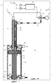
図18及び図19を参照して、第3実施形態に係る流体装置について説明する。本実施形態に係る流体装置1bでは、第1流路系と第2流路系とを短絡する短絡流路が、オリフィス流路34に代えて、移動シリンダ11の外部に現れる短絡配管61を介して形成され、この短絡配管61に流量調整弁62を設けている点で第1実施形態と異なる。流量調整弁62は、その絞り開度を変化させることで通過流量を無段階に調整できる絞り弁であり、かつ、コントローラ44により絞り開度の制御が可能な電動弁である。なお、図19では、都合上、突出部35,36の図示を省略する。
図20及び図21を参照して、第4実施形態に係る流体装置について説明する。本実施形態に係る流体装置1cでは、以下の点で第1実施形態と異なる。すなわち、第1流路系と第2流路系とを短絡する短絡流路が、オリフィス流路34に代えて、移動シリンダ11の外部に現れる2つの短絡配管61a,61bを介して形成され、第1短絡配管61aに第1流量調整弁62aが配設されるとともに第2短絡配管61bに第2流量調整弁62bが配設される点で第1実施形態と異なる。流量調整弁62a,62bは、流量調整弁62と同様の電動弁である。
Claims (11)
- ノズルを介して流体を対象空間に噴射又は前記対象空間から吸引する流体噴射又は吸引装置であって、
中空管状に形成され、両端開口部が閉塞部材で閉塞されたシリンダと、
前記シリンダに前記両端開口部間で相対移動可能に挿嵌されて、前記シリンダの内部を第1流体室と第2流体室とに区画するピストンと、
前記シリンダに挿嵌された前記ピストンから前記閉塞部材を貫通して前記シリンダの外部まで延びて固定され、前記ピストンを支持するとともに前記閉塞部材の貫通孔と摺接して前記シリンダの移動を案内し、前記第1流体室を外部の第1外部配管に連通接続する第1内部流路、及び、前記第2流体室を外部の第2外部配管に連通接続する第2内部流路を有する、前記ピストンよりも周方向外形の面積が小さいガイドと、
前記ノズルのうち前記第1流体室と前記対象空間とを連通する第1ノズルと、
前記ノズルのうち前記第2流体室と前記対象空間とを連通する第2ノズルと、
を備え、
前記第1外部配管及び前記第2外部配管のうち所定圧力の流体を発生させる流体圧力源に連通する配管が順次切り替えられるように構成され、
前記流体圧力源から前記第1ノズル及び前記第2ノズルまでの流路において、前記流体圧力源に連通している流路と前記流体圧力源に連通していない流路とを短絡する短絡流路を有し、前記短絡流路には流路を絞る絞り手段が設けられた、
流体噴射又は吸引装置。 - 前記短絡流路は前記ピストンに形成されて前記第1流体室と前記第2流体室とを連通する、請求項1に記載の流体噴射又は吸引装置。
- 前記絞り手段としてオリフィスを有する、請求項2に記載の流体噴射又は吸引装置。
- 前記ピストンを前記第1流体室側から前記第2流体室側まで貫通する貫通孔が穿設されるとともに、前記貫通孔にはプラグが着脱可能に装着され、
前記短絡流路は前記プラグにおいて前記第1流体室と前記第2流体室とを連通して形成された、請求項2又は請求項3に記載の流体噴射又は吸引装置。 - 前記プラグは前記貫通孔に螺合して装着され、
前記プラグは該プラグの回転軸線と同軸の円錐面を有するとともに、前記貫通孔は前記プラグが装着されたときに前記円錐面と対向する対向円錐面を有し、
前記短絡流路は、前記円錐面と前記対向円錐面との間に形成された隙間を含んで形成され、
前記絞り手段として、前記貫通孔に対する前記プラグの螺合量に応じて前記隙間の間隔が変化する可変絞り弁を有する、請求項4に記載の流体噴射又は吸引装置。 - 前記プラグの前記第2流体室側において、前記第1流体室から前記第2流体室への前記短絡流路を介した流体流入を許容し、かつ、前記第2流体室から前記第1流体室への前記短絡流路を介した流体流入を阻害する弁体を備えた、請求項4又は請求項5に記載の流体噴射又は吸引装置。
- 前記ピストンには前記第1流体室と前記第2流体室とを連通する別の貫通孔がさらに穿設されるとともに、前記別の貫通孔には前記プラグが追加プラグとしてさらに着脱可能に装着され、
前記追加プラグの前記第1流体室側において、前記第2流体室から前記第1流体室への前記短絡流路を介した流体流入を許容し、かつ、前記第1流体室から前記第2流体室への前記短絡流路を介した流体流入を阻害する弁体を備えた、
請求項6に記載の流体噴射又は吸引装置。 - 前記短絡流路は前記シリンダの外部に現れる短絡配管を介して形成され、
前記絞り手段として、前記短絡配管に配設された流量調整弁を有する、請求項1に記載の流体噴射又は吸引装置。 - 前記短絡配管は、前記第1外部配管と前記第2外部配管とを連通接続する、請求項8に記載の流体噴射又は吸引装置。
- 前記短絡配管は、前記第1流体室と前記第2流体室とを連通接続する、請求項8に記載の流体噴射又は吸引装置。
- 前記第1外部配管及び前記第2外部配管のうち前記流体圧力源に連通する配管は、前記流体圧力源と圧力接続管を介して接続された流路切換弁で切り替えられ、
前記短絡配管は、前記流路切換弁を迂回して前記圧力接続管と前記第1外部配管とを連通接続する第1短絡配管と、前記流路切換弁を迂回して前記圧力接続管と前記第2外部配管とを連通接続する第2短絡配管と、で構成され、
前記流量調整弁は、前記第1短絡配管及び前記第2短絡配管にそれぞれ配設された、請求項8に記載の流体噴射又は吸引装置。
Priority Applications (4)
| Application Number | Priority Date | Filing Date | Title |
|---|---|---|---|
| CN202180089115.0A CN116802397B (zh) | 2021-01-06 | 2021-12-28 | 流体注射或抽吸装置 |
| US18/260,165 US12286984B2 (en) | 2021-01-06 | 2021-12-28 | Fluid injection or suction device |
| EP21917779.7A EP4276309B1 (en) | 2021-01-06 | 2021-12-28 | Fluid injection or suction device |
| KR1020237025085A KR102810453B1 (ko) | 2021-01-06 | 2021-12-28 | 유체 분사 또는 흡인 장치 |
Applications Claiming Priority (2)
| Application Number | Priority Date | Filing Date | Title |
|---|---|---|---|
| JP2021-000923 | 2021-01-06 | ||
| JP2021000923A JP7195654B2 (ja) | 2021-01-06 | 2021-01-06 | 流体噴射又は吸引装置 |
Publications (1)
| Publication Number | Publication Date |
|---|---|
| WO2022149559A1 true WO2022149559A1 (ja) | 2022-07-14 |
Family
ID=82357990
Family Applications (1)
| Application Number | Title | Priority Date | Filing Date |
|---|---|---|---|
| PCT/JP2021/048929 Ceased WO2022149559A1 (ja) | 2021-01-06 | 2021-12-28 | 流体噴射又は吸引装置 |
Country Status (6)
| Country | Link |
|---|---|
| US (1) | US12286984B2 (ja) |
| EP (1) | EP4276309B1 (ja) |
| JP (1) | JP7195654B2 (ja) |
| KR (1) | KR102810453B1 (ja) |
| CN (1) | CN116802397B (ja) |
| WO (1) | WO2022149559A1 (ja) |
Families Citing this family (2)
| Publication number | Priority date | Publication date | Assignee | Title |
|---|---|---|---|---|
| US12595811B2 (en) * | 2024-04-30 | 2026-04-07 | Rosenboom Machine & Tool, Inc. | Seal plate method for communicating retract oil to retract side of piston in hydraulic cylinder |
| CN119140309B (zh) * | 2024-11-20 | 2025-04-25 | 四川博科斯电力科技有限公司 | 一种复合材料杆表面自动化喷涂装置 |
Citations (8)
| Publication number | Priority date | Publication date | Assignee | Title |
|---|---|---|---|---|
| JPS489431B1 (ja) * | 1968-02-17 | 1973-03-24 | ||
| JPS63294982A (ja) * | 1987-05-27 | 1988-12-01 | 株式会社三浦鉄工所 | 洗滌装置 |
| JPH09184460A (ja) * | 1995-07-31 | 1997-07-15 | Denso Corp | リターンレス式内燃機関用燃料供給装置及びその調整方法 |
| JPH1157643A (ja) * | 1997-08-12 | 1999-03-02 | Y H Techno:Kk | 伸縮式洗浄装置 |
| WO2002032583A1 (en) * | 2000-10-16 | 2002-04-25 | Kabushiki Kaisha Yokota Seisakusho | Fluid discharge device and pipeline system |
| JP2007229687A (ja) * | 2006-03-03 | 2007-09-13 | Toto Ltd | 吐水装置 |
| JP2016203111A (ja) | 2015-04-24 | 2016-12-08 | 富士フィルター工業株式会社 | 流体噴射・吸引装置 |
| JP2017160890A (ja) * | 2016-03-11 | 2017-09-14 | 株式会社東芝 | 蒸気タービン弁駆動装置 |
Family Cites Families (17)
| Publication number | Priority date | Publication date | Assignee | Title |
|---|---|---|---|---|
| US806779A (en) * | 1903-11-30 | 1905-12-12 | Peter T Coffield | Water-motor. |
| US858226A (en) * | 1906-10-02 | 1907-06-25 | Joseph P Shevlin | Water-motor. |
| US955501A (en) * | 1909-04-22 | 1910-04-19 | George W Coffield | Water-motor. |
| GB302695A (en) | 1928-12-19 | 1930-01-02 | Albert Beyermann | Improvements in double acting pumps |
| US2987051A (en) * | 1958-10-22 | 1961-06-06 | Lodding Engineering Corp | Water-operated oscillator |
| JPS499489B1 (ja) * | 1966-06-21 | 1974-03-05 | ||
| DE2129588C3 (de) | 1971-06-15 | 1975-10-30 | Chemie Und Filter Gmbh, Verfahrenstechnik Kg, 6900 Heidelberg | Dosierpumpe |
| US4034648A (en) * | 1975-12-15 | 1977-07-12 | Dynapac, Inc. | Reciprocating cylinder assembly for self-propelled sprinkler systems |
| GB2046831B (en) | 1979-04-17 | 1983-05-25 | Mac Jannette B | Manually operated beer pump |
| DE3634725A1 (de) | 1986-10-11 | 1988-04-14 | Holzer Walter | Dosierpumpe z.b. fuer insulin |
| FR2681646B1 (fr) | 1991-09-19 | 1995-05-19 | Ody Ste Civile Rech | Pompe comportant un systeme de dosage, et dispositif comportant une telle pompe, pour injection dans un liquide principal d'un additif. |
| US5366159A (en) * | 1992-09-14 | 1994-11-22 | Childers Lance L | Automatic lawn and garden feeding apparatus |
| NL192395C (nl) * | 1994-02-23 | 1997-07-04 | Jan Noord | Reciprocerende zuigermotor werkend op drukmedium. |
| US5715797A (en) * | 1995-06-28 | 1998-02-10 | Nippondenso Co., Ltd. | Fuel supply system for internal combustion engine and method of adjusting it |
| DE19616537C1 (de) | 1996-04-25 | 1997-09-18 | Gerhard Habla | Zeitverzögert ansprechendes Rückschlag-Drosselventil und damit ausgestattete Flüssigkeitssprühanlage |
| US6663360B1 (en) * | 2002-06-25 | 2003-12-16 | James A. Kyer | Fluid injection pump with internal air actuator valve |
| CA2476032C (en) * | 2004-08-27 | 2008-11-04 | Westport Research Inc. | Hydraulic drive system and method of operating a hydraulic drive system |
-
2021
- 2021-01-06 JP JP2021000923A patent/JP7195654B2/ja active Active
- 2021-12-28 WO PCT/JP2021/048929 patent/WO2022149559A1/ja not_active Ceased
- 2021-12-28 CN CN202180089115.0A patent/CN116802397B/zh active Active
- 2021-12-28 US US18/260,165 patent/US12286984B2/en active Active
- 2021-12-28 KR KR1020237025085A patent/KR102810453B1/ko active Active
- 2021-12-28 EP EP21917779.7A patent/EP4276309B1/en active Active
Patent Citations (8)
| Publication number | Priority date | Publication date | Assignee | Title |
|---|---|---|---|---|
| JPS489431B1 (ja) * | 1968-02-17 | 1973-03-24 | ||
| JPS63294982A (ja) * | 1987-05-27 | 1988-12-01 | 株式会社三浦鉄工所 | 洗滌装置 |
| JPH09184460A (ja) * | 1995-07-31 | 1997-07-15 | Denso Corp | リターンレス式内燃機関用燃料供給装置及びその調整方法 |
| JPH1157643A (ja) * | 1997-08-12 | 1999-03-02 | Y H Techno:Kk | 伸縮式洗浄装置 |
| WO2002032583A1 (en) * | 2000-10-16 | 2002-04-25 | Kabushiki Kaisha Yokota Seisakusho | Fluid discharge device and pipeline system |
| JP2007229687A (ja) * | 2006-03-03 | 2007-09-13 | Toto Ltd | 吐水装置 |
| JP2016203111A (ja) | 2015-04-24 | 2016-12-08 | 富士フィルター工業株式会社 | 流体噴射・吸引装置 |
| JP2017160890A (ja) * | 2016-03-11 | 2017-09-14 | 株式会社東芝 | 蒸気タービン弁駆動装置 |
Non-Patent Citations (1)
| Title |
|---|
| See also references of EP4276309A4 |
Also Published As
| Publication number | Publication date |
|---|---|
| EP4276309A1 (en) | 2023-11-15 |
| KR102810453B1 (ko) | 2025-05-21 |
| CN116802397B (zh) | 2026-01-20 |
| KR20230119724A (ko) | 2023-08-16 |
| JP2022106138A (ja) | 2022-07-19 |
| EP4276309B1 (en) | 2026-02-04 |
| US20240060518A1 (en) | 2024-02-22 |
| CN116802397A (zh) | 2023-09-22 |
| US12286984B2 (en) | 2025-04-29 |
| JP7195654B2 (ja) | 2022-12-26 |
| EP4276309A4 (en) | 2024-12-11 |
Similar Documents
| Publication | Publication Date | Title |
|---|---|---|
| WO2022149559A1 (ja) | 流体噴射又は吸引装置 | |
| US9702383B2 (en) | Actuator | |
| US10184540B2 (en) | Liquid pressure device | |
| JP6076880B2 (ja) | 制御弁 | |
| CA2464057A1 (en) | Hydraulic hybrid accumulator shut-off valve | |
| CA2597261A1 (en) | Hydraulic control apparatus | |
| US7013913B2 (en) | Flow control valve | |
| US20170218984A1 (en) | Cylinder device | |
| CN113775687B (zh) | 气缸装置 | |
| US20200011452A1 (en) | Electrically-driven flow rate control valve | |
| US20060086244A1 (en) | Method and system for improving stability of hydraulic systems with load sense | |
| EP4148014B1 (en) | Device for controlled re-entry of a cylinder | |
| CN112161078B (zh) | 一种阀门、分离式平衡阀、行走马达及工程机械装置 | |
| JP7808475B2 (ja) | シリンダ駆動システムおよび振動試験装置 | |
| JP7810414B2 (ja) | 流体噴射又は吸引装置 | |
| US11493061B2 (en) | Control valve assembly for an indirect pneumatic control, and method for controlling a working fluid pressure | |
| CN219969340U (zh) | 一种稳定杆总成及车辆 | |
| CN108758041B (zh) | 一种无泄漏单向顺序阀 | |
| US11320062B2 (en) | Apparatus, systems, and methods for controlling valve actuation speed | |
| DE10229992B4 (de) | Hydraulische Bedienungseinrichtung | |
| CN121552862A (zh) | 一种液压悬架调压装置及调试方法 | |
| JPS5836763A (ja) | パワ−・ステアリング | |
| US10627036B2 (en) | Pressure and headloss maintaining valve system for clean and dirty water systems | |
| JPH1061791A (ja) | サイン流量制御弁 | |
| JPH0341202A (ja) | 流体駆動装置 |
Legal Events
| Date | Code | Title | Description |
|---|---|---|---|
| 121 | Ep: the epo has been informed by wipo that ep was designated in this application |
Ref document number: 21917779 Country of ref document: EP Kind code of ref document: A1 |
|
| DPE1 | Request for preliminary examination filed after expiration of 19th month from priority date (pct application filed from 20040101) | ||
| WWE | Wipo information: entry into national phase |
Ref document number: 18260165 Country of ref document: US |
|
| WWE | Wipo information: entry into national phase |
Ref document number: 202180089115.0 Country of ref document: CN |
|
| ENP | Entry into the national phase |
Ref document number: 20237025085 Country of ref document: KR Kind code of ref document: A |
|
| NENP | Non-entry into the national phase |
Ref country code: DE |
|
| ENP | Entry into the national phase |
Ref document number: 2021917779 Country of ref document: EP Effective date: 20230807 |
|
| WWG | Wipo information: grant in national office |
Ref document number: 18260165 Country of ref document: US |
|
| WWG | Wipo information: grant in national office |
Ref document number: 2021917779 Country of ref document: EP |